Embed Size (px)
Citation preview
Power Plant Engineering
1.1 Introduction
Power plant engineering deals with the study of energy, its sources
and utilization of energy for power generation. The power is generated by
prime movers (example Hydraulic turbines, steam turbines, diesel engines).
Large amount of power is generated using prime movers in a site or layout
called power plants, where all the equipments and machineries required for
power generation is located.
Energy: Energy may be defined as the capacity to do work. Energy
exists in various forms, such as Mechanical Energy, thermal energy,
electrical energy, solar energy etc. Electricity is the only form of energy,
which is easy to produce, easy to transport, easy to use and easy to control.
Electricity consumption per capita is the index of the living standard people
of a place or country i.e. the utilization of energy is an indication of the
growth of the nation.
1.2 Power and Power Plant:
Power is primarily associated with mechanical work and electrical
energy. Therefore, power can be defined as the rate of flow of energy and
1
can state that a power plant is a unit built for production and delivery of a
flow of mechanical or electrical energy. In a common usage, a machine or
assemblage of equipment that produces and delivers a flow of mechanical or
electrical energy is a power plant. Hence an internal combustion engine is a
power plant; a water wheel is a power plant, etc. However, what we
generally mean by the term power plant is that assemblage of equipment,
permanently located on some chosen site which receives raw energy in the
form of a substance capable of being operated on in such a way as to
produce electrical energy for deliver from the power plant.
1.3 Sources of energy
The basic sources of energy for power generation are coal, oil, nuclear
fuels and gas. These sources are known as “conventional sources of energy”.
These sources of energy will one day be used up and are exhaustible.
The most reassuring and promising energy, which is abundant in
supply and is inexhaustible is “Non – conventional sources of energy” such
as solar, wind, tidal, geothermal etc.
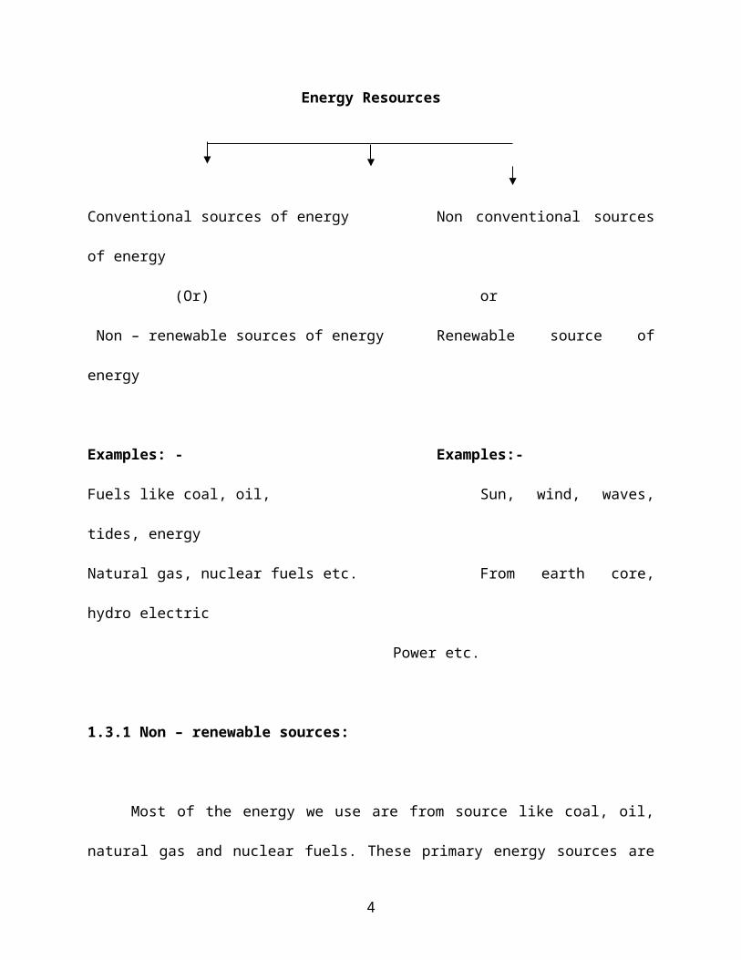
Energy resources can be broadly classified as follows
2
Energy Resources
Conventional sources of energy Non conventional sources of
energy
(Or) or
Non – renewable sources of energy Renewable source of energy
Examples: - Examples:-
Fuels like coal, oil, Sun, wind, waves, tides,
energy
Natural gas, nuclear fuels etc. From earth core, hydro
electric
Power etc.
1.3.1 Non – renewable sources:
Most of the energy we use are from source like coal, oil, natural gas
and nuclear fuels. These primary energy sources are called Non – renewable
sources because once they have been used up, they cannot be replaced.
1.3.2 Renewable sources:
3
Sources of energy that can be used over and over again are called
renewable sources. These sources can be used to produce electricity. Some
of the renewable sources are:
Energy from the sun (Heat and light energy)
Energy from the wind (Kinetic energy)
Energy from the waves and tides (Kinetic energy)
Energy from earth’s core (Geothermal energy)
1.4 Classification of power plants
A power plant makes use of any one of the energy sources to produce
power. Depending on the type of energy source the power plants are
classified as
Thermal power plant (It makes use of coal)
Internal combustion engine plants (makes use of petrol or diesel)
Gas turbine power plant (makes use of a permanent gas)
Nuclear power plant (makes use of nuclear fuels)
Solar power plant (makes use of the suns radiation heat)
Tidal power plant (makes use of the power of tides in the sea)
Hydro electric power plant (makes use of the potential energy of
water)
4
Wind power (makes use of energy available in wind)
Geothermal power plant (makes use of heat energy available under
the ground)
5
1.5 Working principle of Steam power plants
1.5.1 Introduction
Steam power plant is also known as Thermal power plant.
A steam power plant converts the chemical energy of the fossil fuels (coal,
oil, gas) into mechanical / electrical energy. This is achieved by raising the
steam in the boilers, expanding it through the turbines and coupling the
turbines to the generators which convert mechanical energy into electrical
energy as shown in fig. 1.1.
The following two purposes can be served by a steam power plant:
1. To produce electric power
2. To produce steam for industrial purposes besides producing electric
power. The steam may be used for varying purposes in the industries
such as textiles, food manufacture, paper mills, sugar mills and
refineries.
6

Fig. 1.1. Production of Electric energy by steam power plant
1.5.2 Classification of steam power plants
The steam power plants may be classified as follows:
1. Central stations
2. Industrial power stations or captive power stations
1. Central stations. The electrical energy available from these stations
is meant for general sale to the customers who wish to purchase it.
Generally, these stations are condensing type where the exhaust
steam is discharged into a condenser instead of into the atmosphere.
In the condenser the pressure is maintained below the atmospheric
pressure and the exhaust steam is condensed.
7

2. Industrial power stations or captive power stations. This type of
power station is run by a manufacturing company for its own use and
its output is not available for general sale. Normally these plants are
non-condensing because a large quantity of steam (low pressure) is
required for different manufacturing operations.
In the condensing steam power plants the following advantages
accrue:
(i) The amount of energy extracted per kg of steam is increased
(a given size of the engine or turbine develops more power).
(ii) The steam, which has been condensed into water in the
condenser, can be recirculated to the boilers with the help of
pumps.
In a non – condensing steam power plants a continuous supply of fresh
feed water is required which becomes a problem at places where there is a
shortage of pure water.
1.5.3 Layout of modern steam power plant
A steam power plant must have the following equipments:
8
A furnace to burn the fuel.
Steam generator or boiler containing water. Heat generated in the
furnace is utilized to convert water into steam.
Main power unit such as an engine or turbine to use the heat energy
of steam and perform work.
Piping system to convey steam and water.
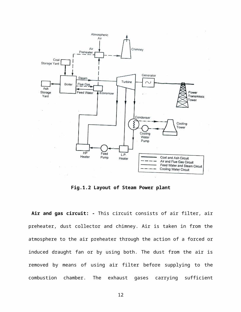
The general layout of the thermal power plant consists of mainly 4
circuits as shown in fig. 1.2. The four main circuits are:
1. Coal and ash circuit
2. Air and gas circuit
3. Feed water and steam flow circuit
4. Cooling water circuit
Coal and ash circuit: - This circuit consists of coal storage, ash storage,
coal handling and ash handling systems. The handling system consists of
belt conveyors, screw conveyors etc. Coal arrives at the storage yard and
after necessary handling, passes on to the furnaces through the fuel feeding
device. Ash resulting from combustion of coal collects at the back of the
boiler and is removed to the ash storage yard through ash handling
equipment. The Indian coal contains 30 to 40% of ash and a power plant of
100MW produces normally 20 to 25 tones of hot ash per hour.
9
Fig.1.2 Layout of Steam Power plant
Air and gas circuit: - This circuit consists of air filter, air preheater, dust
collector and chimney. Air is taken in from the atmosphere to the air
preheater through the action of a forced or induced draught fan or by using
both. The dust from the air is removed by means of using air filter before
supplying to the combustion chamber. The exhaust gases carrying sufficient
quantity of heat and ash are passed through air preheater where the exhaust
10

heat of the gases is given to the air and then it is passed through dust
collectors where most of the dust is removed before exhausting the gases to
the atmosphere through chimney.
Feed water and steam flow circuit: - This circuit consists of boiler feed
pump, boiler, turbine and feed heaters. The steam generated in the boiler is
fed to the steam prime mover to develop the power. The steam coming out
of prime mover is condensed in the condenser and then fed to the boiler with
the help of pump. The condensate is heated in the feed heaters using the
steam tapped from different points of the turbine. The feed heaters may be
of mixed type or indirect heating type.
Some of the steam and water is lost passing through different
components of the system, therefore, feed water is supplied from external
source to compensate this loss. The feed water supplied from external
source is passed through the purifying plant to reduce the dissolved salts to
an acceptable level. The purification is necessary to avoid the scaling of the
boiler tubes.
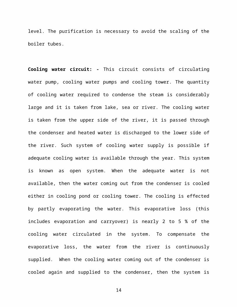
Cooling water circuit: - This circuit consists of circulating water pump,
cooling water pumps and cooling tower. The quantity of cooling water
required to condense the steam is considerably large and it is taken from
lake, sea or river. The cooling water is taken from the upper side of the river,
11
it is passed through the condenser and heated water is discharged to the
lower side of the river. Such system of cooling water supply is possible if
adequate cooling water is available through the year. This system is known
as open system. When the adequate water is not available, then the water
coming out from the condenser is cooled either in cooling pond or cooling
tower. The cooling is effected by partly evaporating the water. This
evaporative loss (this includes evaporation and carryover) is nearly 2 to 5 %
of the cooling water circulated in the system. To compensate the evaporative
loss, the water from the river is continuously supplied. When the cooling
water coming out of the condenser is cooled again and supplied to the
condenser, then the system is known as closed system. When the water
coming out from the condenser is discharged to river downward side directly,
the system is known as open system. Open system is economical than closed
system provided adequate water is available throughout the year.
The different components, which are used in thermal power plants, are
listed below:
Boiler, steam turbine, generator, condenser, cooling towers, circulating
water pump, boiler feed pump, induced/forced draught fans, ash
precipitators etc.
12

1.5.4 Working of the thermal power plant
Steam is generated in the boiler of the thermal power plant using the
heat of the fuel burned in the combustion chamber. The steam generated is
passed through steam turbine where part of its thermal energy is converted
into mechanical energy, which is further used for generating electric power.
The steam coming out of the steam turbine is condensed in the condenser
and the condensate is supplied back to the boiler with the help of the feed
pump and the cycle is repeated.
The function of the boiler is to generate the steam. The function of
condenser is to condensate the steam coming pout of steam turbine at low
pressure. The function of the steam turbine is to convert part of heat energy
of steam into mechanical energy. The function of the pump is to raise the
pressure of the condensate from the condenser pressure (0.015 bar) to
boiler pressure (200 bar). The other components like economiser,
superheater and steam feed heaters (steam from different points of turbine
is fed to the heaters to heat the condensate to a higher temperature) are
used in the primary circuit to increase the overall efficiency of the thermal
power plant.
1.5. 5 Characteristics of steam power plant:
13
Higher efficiency
Lower cost
Ability to burn coal especially high ash content, inferior coals
Reduced environmental impact in terms of air pollution
Reduced water requirement
Higher reliability and availability
1.5.6 Advantages (merits) of thermal power plant
1. The initial cost of construction of the plant is low compared to hydro
electric plant
2. The power plant may be located near the load centre, so that the cost
of transmission and the losses due to transmission are considerably
reduced.
3. The quantity of water in hydroelectric plant depends on nature, such
as rain and rivers. This is not so in the case of thermal power plants.
4. The construction and commissioning of thermal power plant takes
lesser period when compared to hydro electric power plant.
1.5.7. Disadvantages (demerits) of thermal power plant
1. The fuel (coal or oil) used in thermal power plant will one day get
exhausted since it is a non renewable source of energy that is used.
14

2. It cannot be used as peak load plant, as its part load efficiency
decreases very rapidly with decreasing load.
3. The transportation of fuel is a major problem for power plants located
away from coal fields.
4. The cost of power generation is considerably high compared to hydro-
electric power plant.
5. The smoke produced by the burning fuel when exhausted into the
atmosphere causes air pollution.
6. The life of thermal power plant according to the Electricity supply act is
25 years and that of hydroelectric plant is 35 years. The efficiency
decreases to less than 10% after its life period. Hydroelectric power
plant can have a life of even 100 to 125 years.
7. The turbines in thermal power plants run at a speed of 3000 to 4000
rpm and they require special material and rigid construction as
compared to hydro electric plant which has a low running speed of 300
to 400 rpm.
15

1.6 Gas Turbine Power plant
A gas turbine power plant may be defined as one “in which the
principal prime mover is of the turbine type and the working medium is a
permanent gas”.
A simple gas turbine plant consists of the following:
1. compressor
2. Intercooler
3. Regenerator
4. Combustion chamber
5. Gas turbine
6. Reheating unit
1. Compressor:
In gas turbine plant, the axial and centrifugal flow compressors are
used. In most of the gas turbine power plant, two compressors are used. One
is low pressure compressor and the other is high pressure compressor. In low
pressure compressor, the atmospheric air is drawn into the compressor
through the filter. The major part of the power developed by the turbine
(about 66%) is used to run the compressor. This low pressure air goes to the
16
high pressure compressor through the intercooler. Then the high pressure air
goes into the regenerator.
2. Intercooler:
The intercooler is used to reduce the work of the compressor and it is placed
in between the high pressure and low pressure compressor. Intercoolers are
generally used when the pressure ratio is very high. The energy required to
compress the air is proportional to the air temperature at inlet. The cooling
of compressed air in intercooler is generally done by water.
3. Regenerator:
Regenerators are used to preheat the air which is entering into the
combustion chamber to reduce the fuel consumption and to increase the
efficiency. His is done by the heat of the hot exhaust gases coming out of the
turbine.
4. Combustion chambers
Hot air from regenerator flows to the combustion chambers and the fuel like
coal, natural gas or kerosene are injected into the combustion chamber.
17
After the fuel injection, the combustion takes place. This high pressure, high
temperature products of combustion are passed through the turbine.
Fig.1.3 Layout of Gas turbine power plant
18
5. Gas turbine
Two types of gas turbines are used in gas turbine plant.
1. High pressure turbine
2. Low pressure turbine
1. High Pressure turbine
In the beginning, the starting motor runs the compressor shaft. The
burnt gases (product of combustion) expand through the high pressure
turbine. It is important to note that when the turbine shaft rotates it infact
drives the compressor shaft which is couples to it. Now, the high pressure
turbine runs the compressor and the starting motor is stopped. About 66% of
the power developed by the turbine is used to run the compressor and only
34% of the power developed is used to generate electric power.
2. Low pressure turbine
The purpose of the low pressure turbine is to produce electric power.
The shaft of the LPT is coupled with the generator. The burnt fuel (gases)
after leaving the HPT is again sent to a combustion chamber where it further
undergoes combustion.
19
Even if there is any left out unburnt fuel from the previous turbine it
gets fully burnt in the combustion chamber. The burnt gases run the low
pressure turbine (LPT). The shaft of the turbine is directly coupled with the
generator for producing electricity.
The exhaust hot gases after leaving the LPT passes through the
regenerator before exhausted through the chimney into the atmosphere. The
heat from the hot gases is used to preheat the air leaving the HPC before it
enters the combustion chamber. This preheating of the air improves the
efficiency of the combustion chamber.
6. Reheating unit
In this unit, the additional fuel is added to the exhaust gases coming
out from the high pressure turbine, and the reheated combustion products
goes into the low pressure turbine.
1.6.1 Working of Gas Turbine Power plant
The working of gas turbine plant is shown in fig.1.3. The atmosphere
air is drawn into the low pressure compressor through the air filter and it is
compressed.
20
The compressed low pressure air goes into the high pressure
compressor through the intercooler. Here, the heat of the compressed air is
removed. Then the high pressure compressed air goes into the combustion
chamber through the regenerator. In the combustion chamber, the fuel is
added to the compressed air and the combustion of the fuel takes place.
The product of the combustion goes into the high pressure turbine. The
exhaust of the high pressure turbine goes to another combustion chamber
and the additional fuel is added and it goes to the low pressure turbine.
After the expansion in the low pressure turbine, the exhaust is used to
heat the high pressure air coming to the combustion chamber through the
regenerator. After that, the exhaust goes to the atmosphere.
1.6.2..Advantages of Gas turbine power plant
1. For a gas turbine plant, Natural gas is a very suitable fuel. It would be
ideal to install gas turbine plants near the site where natural gas is
readily available.
2. Gas turbine plants can work economically for short running hours.
3. Storage of fuel requires less area and handling is easy.
4. Gas turbine plant is small and compact in size as compared to steam
power plants.
5. It can be started quickly and can be put on load in a very short time.
21

6. The cost of maintenance is less.
7. It is simple in construction. There is no need for boiler, condenser and
other accessories as in the case of steam power plants.
8. The gas turbine can operate at high speed since there are no
reciprocating parts
9. Cheaper fuel such as kerosene, paraffin, benzene and powdered coal
(cheaper than petrol and diesel) can be used.
10. Gas turbine plants can be used in water scarcity areas
11. Less pollution and less water is required.
1.6.3 Disadvantages of gas turbine power plant
1. 66% of the power developed is used to drive the compressor; the gas
turbine unit has a low thermal efficiency
2. The running speed of the gas turbine is in the range of (40, 000 to 1,
00,000 rpm) and the operating temperature is as high as 2000 0C, for
this reason special metals and alloys have to be used for the various
parts of the turbine.
3. Special cooling methods are required for cooling the turbine blades.
4. It is difficult to start a gas turbine as compared to a diesel engine in a
diesel power plant
5. The life of a gas turbine plant is upto 10 years, after which its
efficiency decreases to less than 10 percent.
22

1.6.4 Applications of gas turbine power plant
To drive generators and supply loads in steam, diesel or hydro plants
To work as combination plants with conventional steam boilers
Thermal process industries
Petro chemical industries
Power generation (used for peak load and as stand by unit)
Aircraft and ships for their propulsion. They are not suitable for
automobiles because of their very high speeds.
1.6.5 Classification of Gas Turbine
Gas turbines may be broadly classified as:
(i) Open cycle gas turbine
(ii) Closed cycle gas turbine
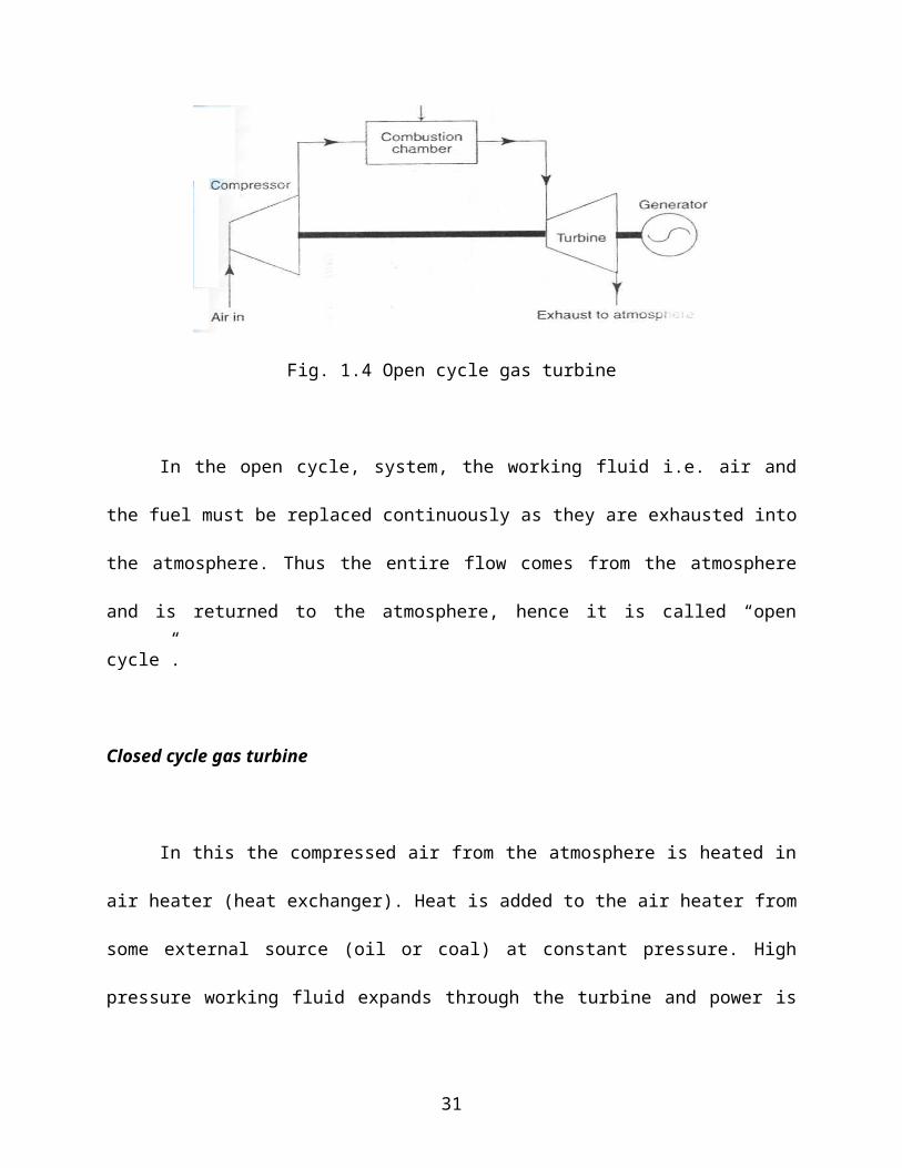
Open cycle gas turbine
In the open cycle gas turbine, fig.1.4, air is drawn into the compressor
from the atmosphere. The compressed air is heated by directly burning the
fuel in the air at constant pressure inside the combustion chamber. The high
23
pressure hot gases from the combustion chamber drive the turbine and the
power is developed when the turbine shaft rotates.
Gas turbines are not self starting. A starting motor drives the compressor till
fuel is injected inside the combustion chamber, once the turbine starts
gaining speed the starting motor is disengaged.
Part of the power developed by the gas turbine (about 60%) is used to
drive the compressor and the remaining is used to drive a generator or other
machinery.
Fig. 1.4 Open cycle gas turbine
In the open cycle, system, the working fluid i.e. air and the fuel must
be replaced continuously as they are exhausted into the atmosphere. Thus
the entire flow comes from the atmosphere and is returned to the
atmosphere, hence it is called “open cycle”.
24
Closed cycle gas turbine
In this the compressed air from the atmosphere is heated in air heater
(heat exchanger). Heat is added to the air heater from some external source
(oil or coal) at constant pressure. High pressure working fluid expands
through the turbine and power is developed. The exhaust working fluid is
cooled in a pre cooler before the same fluid is sent into the compressor
again.
Fig. 1.4 Closed cycle gas turbine
In a closed cycle gas turbine the same working fluid is continuously
circulated. The fuel required for adding heat from an external source can be
any fuel ranging from kerosene, to heavy oil and even peat and coal slurry
without reducing the efficiency.
1.7 Diesel power plant
1.7.1 Introduction
25

This is a fossil fuel plant since diesel is a fossil fuel. Diesel engine power
plants are installed where supply of coal and water is not available in
sufficient quantity.
(i) These plants produce the power in the range of 2 to 50 MW.
(ii) They are used as standby sets for continuity of supply such as
hospitals, telephone exchanges, radio stations, cinema theatres and
industries.
(iii) They are suitable for mobile power generation and widely used in
railways and ships.
(iv) They are reliable compared to other plants.
(v) Diesel power plants are becoming more popular because of
difficulties experienced in construction of new hydel plants and
thermal plants
1.7.2 Layout of Diesel Power plant
The essential components of diesel power plant are
Diesel engine
Air filter and super charger
Engine starting system
26
Fuel system
Lubrication system
Cooling system
Governing system
Exhaust system
Diesel engine:
This is the main component of a diesel power plant. The engines are
classified as two stroke engine and four stroke engines. Engines are
generally directly coupled to the generator for developing power. In diesel
engines, air admitted into the cylinder is compressed. At the end of
compression stroke, fuel is injected. The fuel is burned and the burning
gases expand and do work on the piston. The shaft of the engine is directly
coupled to the generator. After the combustion, the burned gases are
exhausted to the atmosphere.
Air filter and supercharger
The air filter is used to remove the dust from the air which is taken by
the engine. Air filters may be of dry type, which is made up of felt, wool or
cloth. In oil bath type of filters, the air is swept over a bath of oil so that dust
particles get coated. The function of the supercharger is to increase the
27
pressure of the air supplied to the engine and thereby the power of the
engine is increased.
Engine starting system
Diesel engine used in diesel power plants is not self starting. Engine
starting system includes air compressor and starting air tank. This is used to
start the engine in cold conditions by supplying the air.
Fuel system
It includes the storage tank, fuel pump, fuel transfer pump, strainers and
heaters. Pump draws diesel from the storage tank and supplies it to the
small day tank through the filter. Day tank supplies the daily fuel need for
the engine. The day tank is usually placed high so that diesel flows to engine
under gravity.
Diesel is again filtered before being injected into the engine by the fuel
injection pump. The fuel injection system performs the following functions.
Filter the fuel
Meter the correct quantity of the fuel to be injected
28
Time the injection process
Regulate the fuel supply
Secure fine atomization of fuel oil
Distribute the atomized fuel properly in the combustion;
chamber.
The fuel is supplied to the engine according to the load on the plant.
Lubrication system
It includes oil pumps, oil tanks, coolers and pipes. It is used to reduce
the friction of moving parts and reduce wear and tear of the engine parts
such as cylinder walls and piston. Lubrication oil which gets heated due to
the friction of the moving parts is cooled before recirculation.
In the lubrication system the oil is pumped from the lubricating oil tank
through the oil cooler where the oil is cooled by the cold water entering the
engine. The hot oil after cooling the moving parts return to the lubricating oil
tank.
29

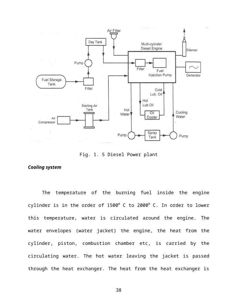
Fig. 1. 5 Diesel Power plant
Cooling system
The temperature of the burning fuel inside the engine cylinder is in the
order of 15000 C to 20000 C. In order to lower this temperature, water is
circulated around the engine. The water envelopes (water jacket) the engine,
the heat from the cylinder, piston, combustion chamber etc, is carried by the
circulating water. The hot water leaving the jacket is passed through the
heat exchanger. The heat from the heat exchanger is carried away by the
raw water circulated through the heat exchanger and is cooled in the cooling
tower.
30
Governing system
It is used to regulate the speed of the engine. This is done by varying
the fuel supply according to the engine load.
31

Exhaust system
The exhaust gases coming out of the engine is very noisy. In order to
reduce the noise a silencer (muffler) is used.
1.7.3 Working of Diesel Power Plant
The air and fuel mixture act as a working medium in diesel engine
power plant. The atmosphere air enters inside the combustion chamber
during the suction stroke and the fuel is injected through the injection pump.
The air and fuel is mixed inside the engine and the charge is ignited due to
high compression inside the engine cylinder. The basic principle in diesel
engine is that, the thermal energy is converted into mechanical energy and
this mechanical energy is converted into electrical energy to produce the
power by using generator or alternator.
1.7.4 Applications of Diesel Engines in Power Field
The diesel electric power plants are chiefly used in the following
field.
32
(a) Peak load plant: Diesel plants can be used in combination with
thermal or hydro-plants as peak load units. They can be easily started or
stopped at a short notice to meet the peak demand.
(b) Mobile plant: Diesel plants mounted on trailers can be used for
temporary or emergency purposes such as for supplying power to large civil
engineering works.
(c) Standby unit: If the main unit fails or cannot cope up with the demand,
a diesel plant can supply the necessary power. For example, if water
available in a hydro-plant is not adequately available due to less rainfall, the
diesel station can operate in parallel to generate the short fall in power.
(d) Emergency plant: During power interruption in a vital unit like a key
industrial plant or a hospital, a diesel electric plant can be used to generate
the needed power.
(e) Nursery station: In the absence of main grid, a diesel plant can be
installed to supply power in a small town. In course of time, when electricity
from the main grid becomes available in the town, the diesel unit can be
shifted to some other area which needs power on a small scale. Such a diesel
plant is called a "nursery station".
33

(f) Starting stations: Diesel units can be used to run the auxiliaries (like
FD and ID fans, BFP, etc.) for starting a large steam power plant.
(g) Central stations :Diesel electric plants can be used as central station
where the capacity required is small
1.7.5 Advantages and disadvantages of diesel power plant
Following are the advantages of diesel electric stations.
1. It is easy to design and install these electric stations.
2. They are easily available in standard capacities.
3. They can respond to load changes without much difficulty.
4. There are less standby losses.
5. They occupy less space.
6. They can be started and stopped quickly.
7. They require less cooling water.
8. Capital cost is less.
9. Less operating and supervising staff required.
10. High efficiency of energy conversion from fuel to
electricity.
11. Efficiency at part loads is also higher.
12. Less of civil engineering work is required.
34
13. They can be located near the load centre.
14. There is no ash handling problem.
15. Easier lubrication system.
1.7.6 Disadvantages in installing diesel units for power
generation.
1. High operating cost.
2. High maintenance and lubrication cost.
3. Capacity is restricted. Cannot be of very big size.
4. Noise problem.
5. Cannot supply overload.
6. Unhygienic emissions.
7. The life of the diesel power plant is less (7 to 10 years) as
compared to that of a steam power plant which has a life span
of 25 to 45 years. The efficiency of the diesel plant decreases
to less than 10% after its life period.
1.8 Hydroelectric power plant
1.8.1 Working principle
35
Hydroelectric power plant (Hydel plant) utilizes the potential energy of
water stored in a dam built across the river. The potential energy of the
stored water is converted into kinetic energy by first passing it through the
penstock pipe. The kinetic energy of water is then converted into mechanical
energy in a water turbine. The turbine is coupled to the electric generator.
The mechanical energy available at the shaft of the turbine is converted into
electrical energy by means of the generator.
Because gravity provides the force which makes the water fall, the
energy stored in the water is called gravitational potential energy.
Fig. 1.6 Principle of Hydro electric plant
1.8.2 Layout of Hydro electric power plant
36

Fig.1.7 shows the schematic representation of a Hydro electric power
plant. The main components are
Water reservoir
Dam
Spillway
Gate
Pressure tunnel
Surge tank
Penstock
Water turbine
Draft tube
Tail race level
Power house
Water reservoir: In a reservoir the water collected from the catchment
area during rainy season is stored behind a dam. Catchment area gets its
water from rains and streams. Continuous availability of water is a basic
necessity for a hydroelectric power plant. The level of water surface in the
reservoir is called Head water level. The water head available for power
generation depends on the reservoir height.
37
Dam: the purpose of the dam is to store the water and to regulate the out
going flow of water. The dam helps to store all the incoming water. It also
helps to increase the head of the water. In order to generate a required
quantity of power, it is necessary that a sufficient head is available.
Spillway: Excess accumulation of water endangers the stability of dam
construction. Also in order to avoid the overflow of water out of the dam
especially during rainy seasons spillways are provided. This prevents the rise
of water level in the dam. Spillways are passages which allow the excess
water to flow to a different storage area away from the dam.
Gate: A gate is used to regulate or control the flow of water from the dam.
Pressure tunnel: It is a passage that carries water from the reservoir to the
surge tank.
Surge tank: A surge tank is a small reservoir or tank in which the water
level rises or falls due to sudden changes in pressure. There may sudden
increase of pressure in the penstock pipe due to sudden backflow of water,
as load on the turbine is reduced. This sudden rise of pressure in the
penstock pipe is known as water hammer.
38
Fig. 1.7 Layout of Hydro electric Power plant
A surge tank is introduced between the dam and the turbine and serves
the following purposes:
1. To reduce the distance between the free water surface in the dam and
the turbine, thereby reducing the water hammer effect. Otherwise,
penstock will be damages by the water effect.
2. To serve as a supply tank to the turbine when the water in the pipe is
accelerated during increased load conditions and as a storage tank
when the water is decelerating during reduced load conditions.
Penstock: Penstock pipe is used to bring water from the dam to the
hydraulic turbine. Penstock pipes are made up of steel or reinforced
39
concrete. The turbine is installed at a lower level from the dam. Penstock is
provided with a gate valve at the inlet to completely close the water supply.
It has a control valve to control the water flow rate into the turbine.
Water turbine or hydraulic turbine (Prime mover): The hydraulic
turbine converts the energy of water into mechanical energy. The
mechanical energy (rotation) available on the turbine shaft is coupled to the
shaft of an electric generator and electricity is produced. The water after
performing the work on turbine blade is discharged through the draft tube.
The prime movers which are in common use are Pelton wheel, Kaplan
turbine, Francis turbine.
Draft tube: Draft tube is connected to the outlet of the turbine. It converts
the kinetic energy available in the water into pressure energy in the
diverging portion. Thus, it maintains a pressure of just above the above the
atmospheric at the end of the draft tube to move the water into a tail race.
Water from the tail race is released for irrigation purposes.
Tail race level: Tail race is a water path to lead the water discharged from
the turbine to the river or canal. The water held in the tail race is called Tail
race water level.
40
Power House: The power house accommodates the water turbine,
generator, transformer and control room. As the water rushes through the
turbine, it spins the turbine shaft, which is coupled to the electric generator.
The generator has a rotating electromagnet called a rotor and a stationary
part called a stator. The rotor creates a magnetic field that produces an
electric charge in the stator. The charge is transmitted as electricity. The
step up transformer increases the voltage of the current coming from the
stator. The electricity is distributed through power lines.
41
1.8.3 Classification of Hydro electric power plant
Hydro electric power plants are usually classified according to the
available of head of water
High head power plants
Medium head power plants
Low head power plants
High head power plants: When the operating head of water exceeds 70
meters, the plant is known as High head power plant. Pelton wheel turbine is
the prime mover used.
Medium head power plants: When the water ranges from 15 to 70
meters, then the power plant is known as Medium head power plant. It uses
Francis Turbine.
Low head power plants: When the head is less than 15 meters, the plant
is named as Low head power plant. It uses Francis or Kaplan turbine as prime
mover.
1.8.4 Advantages of hydro electric power plant
42
1. Water source is perennially available. No fuel is required to be burnt to
generate electricity. It is aptly termed as 'the white coal'. Water passes
through turbines to produce work and downstream its utility remains
undiminished for irrigation of farms and quenching the thirst of people
in the vicinity.
2. The running costs of hydropower installations are very low as
compared to thermal or nuclear power stations. 1n thermal stations,
besides the cost of fuel, one has to take into account the
transportation cost of the fuel also.
3. There is no problem with regards to the disposal of ash as in a thermal
station. The problem of emission of polluting gases and particulates to
the atmosphere also does not exist. Hydropower does not produce any
greenhouse effect, cause the pernicious acid rain and emit obnoxious
NO.
4. The hydraulic turbine can be switched on and off in a very short time.
In a thermal or nuclear power plant the steam turbine is put on turning
gear for about two days during start-up and shut-down. .
5. The hydraulic power plant is relatively simple in concept and self-
contained in operation. Its system reliability is much greater than
that of other power plants.
6. Modern hydropower equipment has a greater life expectancy and can
easily last 50 years or more. This can be compared with the effective
life of about 30 years of a thermal or nuclear station.
43
7. Due to its great ease of taking up and throwing off the load, the hydro-
power can be used as the ideal spinning reserve in a system mix of
thermal, hydro and nuclear power stations.
8. Modern hydro-generators give high efficiency over a considerable
range of load. This helps in improving the system efficiency.
9. Hydro-plants provide ancillary benefits like irrigation, flood control,
afforestation, navigation and aqua-culture.
10. Being simple in design and operation, the hydro-plants do not
require highly skilled workers. Manpower requirement is also low.
1.8.5 Disadvantages of Water Power
1. Hydro-power projects are capital-intensive with a low rate of return.
The annual interest of this capital cost is a large part of the annual cost
of hydropower installations.
2. The gestation period of hydro projects is quite large. The gap between
the foundation and completion of a project may extend from ten to
fifteen years.
3. Power generation is dependent on the quantity of water available,
which may vary from season to season and year to year. If the rainfall
is in time and adequate, then only the satisfactory operation of the
plant can be expected.
44
4. Such plants are often far way from the load centre and require long
transmission lines to deliver power. Thus the cost of transmission lines
and losses in them are more.
5. Large hydro-plants disturb the ecology of the area, by way of
deforestation, destroying vegetation and uprooting people. Strong
public opinion against. Erection of such plants is a deterrent factor. The
emphasis is now more on small, mini and micro hydel stations.
1.8.6 Hydro electric power plant in India
Srisailam Hydel power plant – AP – 770 MW
Upper sileru Hydor electric project – AP - 120
Kodayar hydro electric power plant – TN – 100 MW
Iddiki hydel project – Kerala – 800 MW
45

1.9 Nuclear power plant
1.9.1. Introduction
As large amounts of coal and petroleum are being used to produce
energy, time may come when their reserves may not be able to meet the
energy requirements. Thus there is tendency to seek alternative sources of
energy. The discovery that energy can be liberated by the nuclear fission of
materials like uranium (U), Plutonium (Pu), has opened up a new source of
power of great importance. The heat produced due to fission of U and Pu is
used to heat water to generate steam which is used for running
turbogenerator.
It has been found that one kilogram of U can produce as much energy
as can be produced by burning 4500 tonnes of high grade coal. This shows
that nuclear energy can be successfully employed for producing low cost
energy in abundance as required by the expanding and industrializing
population of future.
Some of the factors which go in favor of nuclear energy are as follows:
46

1. Hydro electric power is of storage type and is largely dependent of
monsoons. The systems getting power from such plants have to shed
load during the period of low rainfall.
2. Oil is mainly needed for transport, fertilizers and petrochemicals and
thus cannot be used in large quantities for power generation.
3. Coal is available only in some parts of the country and transportation
of coals requires big investments.
4. Nuclear power is partially independent of geographical factors, the
only requirement being there should be reasonably good supply of
water. Fuel transportation networks and larger storage facilities are not
needed and nuclear power plant is a clean source of power which does
not pollute the air if radioactive hazards are effectively prevented.
5. Large quantity of energy is released with consumption of only a small
amount of fuel.
1.9.2 Nuclear fission
The fuel inside the reactor is a metal called uranium. Uranium exists as
an isotope in the form of U235, U234 and U238. Out of these isotopes U235 is more
unstable. When a neutron is captured by a nucleus of an atom of U235, it
splits up roughly into two equal fragments and about 2.5 neutrons are
released and a large amount of energy (nearly 200 million electron volts
MeV) is produced. This is called fission process. The neutrons so produced
47

are very moving neutrons and can be made to fission other nuclei of U235
thus enabling a chain reaction to take place. When a large number of fission
occurs, enormous amount of heat is produced. The following fig.1.8. shows
the chain reaction
Fig. 1.8 Nuclear Fission
It may be observed from the fig.1.8 that 2.5 neutrons are released in
fission of each nucleus of U235, out of these one neutron is used to sustain the
chain reaction, 0.9 neutrons is absorbed by U238 and becomes Pu239. The
remaining 0.6 neutrons escape from the reactor. Moderators are provided to
slow down the neutrons from the high velocities but not to absorb them. The
moderators which are commonly used are ordinary water and Heavy water.
The fig.1.9 shows how the reactor is put on and off.
48
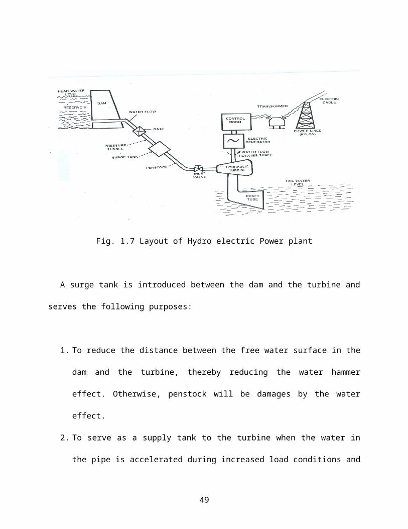
Fig. 1.9 Control rods
Control rods limit the number of fuel atoms that can split. They are
made up of a material that absorbs neutrons. To turn on the reactor some
rods are pulled out. The rods are made of boron or cadmium.
1.9.3 Main components of a nuclear power plant
The main components of a nuclear power plant are
Nuclear fuel
Nuclear reactor
Steam generator
Moderator
Control rods
49
Reflector
Turbine
Condenser
Shielding
Nuclear Fuel: Fuel of a nuclear reactor should be fissionable material which
can be defined as an element or isotope whose nuclei can be caused to
undergo nuclear fission by nuclear bombardment and to produce a fission
chain reaction. It can be one or all of the following U235, U233 and Pu239
Nuclear reactor: A nuclear reactor may be regarded as a substitute for the
boiler furnace of a steam power plant. Heat is produced in the reactor due to
nuclear fission of the fuel. During the fission process, the large amount of
heat is liberated. This large amount of heat is absorbed by the coolant and it
is circulated through the core.
The various types of reactors used in nuclear power plant is
1. Boiling water reactor
2. Pressurised water reactor
3. Fast breeder reactor
Steam generator: The heat liberated in the reactor is taken up by the
coolant circulating through the core. The purpose of the coolant is to transfer
50

the heat generated in the reactor core and use it for steam generation.
Ordinary water or heavy water is a common coolant.
Moderator: It is used to reduce the kinetic energy of fast neutrons into slow
neutrons and to increase the probability of chain reaction. Graphite, heavy
water and beryllium are generally used as moderator. A moderator should
possess the following properties:
1. It should have high thermal conductivity
2. It should be available in large quantities in pure form
3. It should have high melting point in case of solid moderators and low
melting point in case of liquid moderators. Solid moderators should
also possess good strength and machinability.
4. It should provide good resistance to corrosion
5. It should be stable under heat and radiation
6. It should be able to slow down neutrons
Control rods: They regulate the rate of a chain reaction. They are made of
boron, cadmium or other elements which absorb neutrons. Control rods
should posses the following properties:
1. They should have adequate heat transfer properties
2. They should be stable under heat and radiation
3. They should be corrosion resistant
51
4. They should be sufficient strong and should be able to shut down the
reactor almost instantly under all conditions.
5. They should have sufficient cross sectional area for the absorption.
Reflector: The neutrons produced during the fission process will be partly
absorbed by the fuel rods, moderator, coolant or structural material etc.
Neutrons left unabsorbed will try to leave the reactor core and will be lost.
Such loss is minimized by surrounding the reactor core by a material called
reflector which will send the neutrons back into the core. The returned
neutrons can then cause more fission and improve the neutrons economy of
the reactor. Generally the reflector is made up of graphite and beryllium.
Turbine: The steam produced in the steam generator is passed to the
turbine. Work is done by the expansion of stem in the turbine.
Condenser: The exhaust steam from the turbine flows to the condenser
where cooling water is circulated. The exhaust steam is condensed to water
in the condenser by cooling. The condensate is pumped again into the steam
generator by the feed pump.
Shielding: The reactor is a source of intense radioactivity. These radiations
are very harmful and shielding is provided to absorb the radioactive rays. A
52
thick concrete shielding and a pressure vessel are provided to prevent the
radiations escaped to atmosphere.
1.9.4 Working of a Nuclear Power plant
The reactor of a nuclear power plant is similar to the furnace of steam
power plant. The heat liberated in the reactor due to the nuclear fission of
the fuel is taken up by the coolant circulating through the reactor core. Hot
coolant leaves the reactor at top and then flows through the tubes of steam
generator (boiler) and passes on its heat to the feed water. The steam
produced is passed through the turbine and after work has been done by
expansion of steam in the turbine, steam leaves the turbine and flows to
condenser. Pumps are provided to maintain the flow of coolant, condensate
and feed water.
1.9.5 Boiling water reactor (BWR)
In this reactor, enriched uranium (enriched uranium contains more
fissionable isotope U235 than the naturally occurring percentage 0.7% as
nuclear fuel and water is used as coolant. Water enters the reactor at the
bottom. It takes up the heat generated due to the fission of fuel and gas
converted into steam. Steam leaves the reactor at the top and flows into the
turbine. Water also serves as moderator. India’s first nuclear power plant at
53
Tarapur has two reactors (each of 200 MW capacity) of boiling water reactor
type.
Fig. 1.10 Boiling water reactor
54

1. 9.6 Pressurised Water reactor (PWR)
Fig. 1.11 Pressurised Water Reactor
A pressurised water nuclear plant is shown in fig. It uses enriched
uranium as fuel. Water is used as coolant and moderator. Water passes
through the reactor core and takes up the heat liberated due to nuclear
fission of the fuel. In order that water may not boil (due to its low boiling
point 2120 F at atmospheric conditions) and remain in liquid state, it is kept
under a pressure of about 1200 p.s.i.g in the pressuriser. This enables water
to take up more heat from the reactor. From the pressuriser, water flows to
the steam generator where it passes on its heat to the feed water which in
turn gets converted into steam.
55
1.9.7 Fast breeder reactor (FBR)
In this reactor the core containing U235 is surrounded by a blanket (a
layer of fertile material placed outside the core) or fertile material U238. In
this reactor no moderator is used. The fast moving neutrons liberated due to
fission of U235 are absorbed by U238 which gets converted into fissionable
material Pu239, Pu239 is capable of sustaining chain reaction. Thus the reactor
is important because it breeds fissionable material from fertile material U238
available in large quantities. This reactor uses two liquid metal coolant
circuits. Liquid sodium is used as primary coolant when circulated through
the tubes of intermediate heat exchanger transfer its heat to secondary
coolant sodium potassium alloy. The secondary coolant while flowing through
the tubes of steam generator, transfer its heat to feed water.
Fast breeder reactors are better than conventional reactor both from
the point of view of safety and thermal efficiency. For India which already is
fast advancing towards self reliance in the field of nuclear power technology,
the fast breeder reactor becomes inescapable in view of the massive
reserves of thorium and the finite limits of its uranium resources.
1.9.8 Advantages of nuclear power plant
56

1. The fuel used in nuclear power plant is uranium; it does not release
chemical or solid pollutants into the air during use.
2. Space required is less when compared with other power plants.
3. Fuel consumption is very less.
4. Fuel transportation cost is low and no large storage area for fuel is
required.
5. The plant is not affected by weather conditions. The plant can function
throughout the year (Hydel power plants depends on monsoon)
6. By using nuclear fuel we can conserve the fossil fuels like coal, oil, gas
etc for other purposes. For example coal can be used to power steam
engines, oil can be used for running vehicles, and gas be used for
cooking.
7. Number of workers required is less.
8. Nuclear power plant is the only source which can meet the increasing
demand of electricity.
9. A nuclear power plant uses much less fuel than a fossil fuel plant
1 metric ton of uranium fuel = 3 million metric tons of coal = 12 million
barrels of oil
1.9.9 Disadvantages of nuclear power plant
57
1. Nuclear plants cost more to build than thermal or hydro electric
power plants of the same capacity.
2. Radioactive wastes must be disposed carefully, otherwise it will
adversely affect the health of workers and the environment as a
whole.
3. Maintenance cost of the plant is high.
4. Not suitable for varying load conditions
5. Well trained persons are required to operate the plant.
1.9.10 Nuclear power stations in India
Tarapur Nuclear power station (Bombay) – Boiling water reactor –
200 MW
Rana Pratap Sagar Nuclear power station (Kota in Rajasthan) – Two
200 MW
Kalpakkam Nuclear power station – Two 235 MW – Pressurised
water reactor
Narora Nuclear power station (Uttar Pradesh) – Two 235 MW –
CANDU reactor
Kakarpur Nuclear power plant (Gujarat) – 4 235 MW CANDU type
reactor
58