Embed Size (px)
Citation preview
Electron Cooling Commissioning UpdateElectron Cooling Commissioning Update
Run II meetingMay 12, 2005
L. Prost, Ecool Group

Electron Cooling Commissioning Update 2
OutlineOutline
Goal, design, plan, installation highlights… Commissioning progress highlights Some specifics of what has been achieved What’s ahead, some important issues that
remain Conclusion

Electron Cooling Commissioning Update 3
People of EcoolPeople of Ecool Recycler department head:
Sergei Nagaitsev Recycler deputy
department head: Cons Gattuso
Ecool Project engineer: Jerry Leibfritz
Ecool Safety officer: Mike Gerardi
Electron cooling group: Alexey Burov Kermit Carlson Grigory Kazakevich Tom Kroc Lionel Prost Sasha Shemyakin (GL) Mary Sutherland Vitali Tupikov Arden Warner
Recycler department personnel:
Valeri Balbekov Dan Broemmelsiek Jim Crisp Martin Hu Dave Johnson Dave Neuffer Bill Ng Stan Pruss Meiqin Xio
Other AD departments: Brian Chase Paul Joireman Ron Kellett Brian Kramper Valeri Lebedev Mike McGee Jerry Nelson Lucy Nobrega Greg Saewert Chuck Schmidt Alexei Semenov Sergey Seletskiy Karl Williams

Electron Cooling Commissioning Update 4
Electron Cooling: Long. Rate Design GoalElectron Cooling: Long. Rate Design Goal
Cooling needed: 30 eV-s per hour To minimize the IBS rate, a 65-eV-s stack will
be kept in a 4-μs long bunch; 95% of particles will have its energy offset ≤8 MeV.
For particles with ΔE ≈ 8 MeV the drag rate needs to be about 4 MeV/hr to cool 15 eV-s in 30 minutes.

Electron Cooling Commissioning Update 5
Performance goal for the long. equilibrium emittance: 54 Performance goal for the long. equilibrium emittance: 54 eV-seV-s
0
10
20
30
40
50
60
70
80
90
100
0 100 200 300 400 500 600
Pbar intensity, xE10
Lo
ng
em
itta
nc
e (
95
%),
eV
-s Recycler (measured)
Accumulator (measured)
Ecool performance goal
Electron Cooling Commissioning Update 6
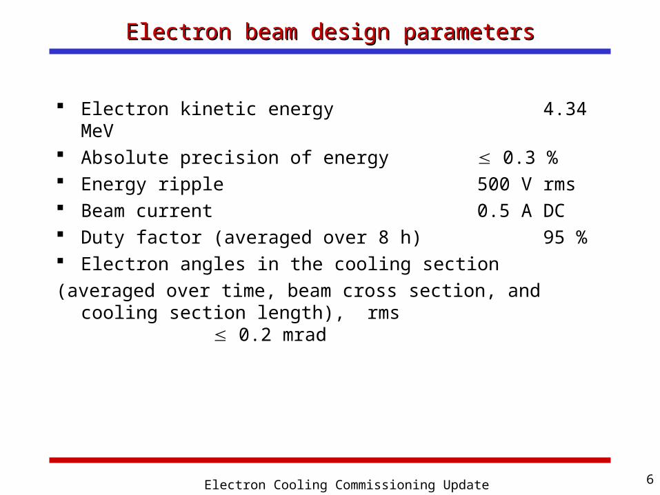
Electron beam design parametersElectron beam design parameters
Electron kinetic energy 4.34 MeV Absolute precision of energy 0.3 % Energy ripple 500 V rms Beam current 0.5 A DC Duty factor (averaged over 8 h) 95 % Electron angles in the cooling section(averaged over time, beam cross section, and cooling
section length), rms 0.2 mrad

Electron Cooling Commissioning Update 7
Commissioning challengeCommissioning challenge
Technical issues not fully resolved with prototype system at Wide Band Poor reliability of operation at 4.3 MV Insufficient quality of the cooling section magnetic
field High beam losses Low-frequency electron beam motion Inadequate protection system
Concurrently attain stable operation at 4.3 MV, 0.5 A with rms angular spread < 0.2 mrad in cooling section

Electron Cooling Commissioning Update 8
Commissioning guiding principlesCommissioning guiding principles
Establish ‘some’ beam and verify optics (pulsed beam, first order) Choice of a pulsed beam over low-current DC beam Check polarities, calibration,… of all lenses and
correctors
Increase beam intensity (pulsed → DC) Low current loss to maintain recirculation
Make the beam cold (i.e. good understanding of the optics and beam control) Only way to achieve cooling
Maintain hardware integrity (i.e. avoid drilling a hole !) U-Bend mode to develop and test protection systems

Electron Cooling Commissioning Update 9
The commissioning project The commissioning project planplan summary summary
On Feb 1, 2005 the Recycler starts to contribute to HEP luminosity (mixed-source operations). This continues uninterrupted until about Apr 1, 2005.
On Feb 1, 2005 the effort switches over to the electron beam commissioning. Pelletron and U-bend start-up
On Mar 15, 2005 start commissioning of the complete electron beamline. Run electron beam in a pulsed mode Pbar operations are uninterrupted
On Apr 4, 2005 start establishing a DC beam. The Recycler beam may be interrupted Investigate and correct MI ramp effects on the electron
beam Minimize the effects of the electron beam on the Recycler
beam, start running pbar and electron beams concurrently Establish a 500-mA dc electron beam by July 08, 2005
Electron Cooling Commissioning Update 10
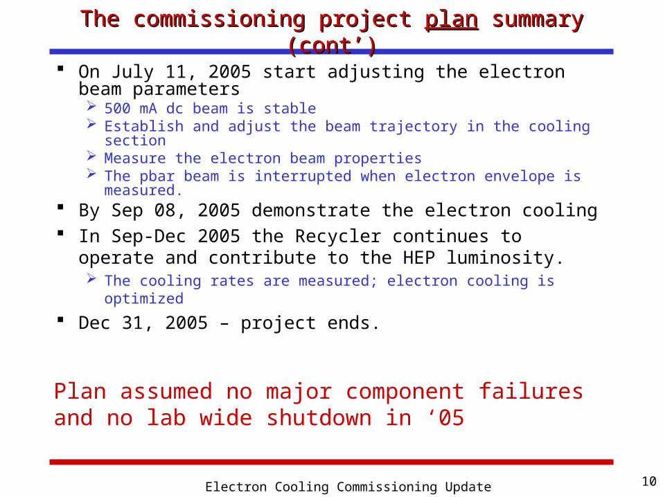
The commissioning project The commissioning project planplan summary (cont’) summary (cont’)
On July 11, 2005 start adjusting the electron beam parameters 500 mA dc beam is stable Establish and adjust the beam trajectory in the cooling section Measure the electron beam properties The pbar beam is interrupted when electron envelope is
measured. By Sep 08, 2005 demonstrate the electron cooling In Sep-Dec 2005 the Recycler continues to operate
and contribute to the HEP luminosity. The cooling rates are measured; electron cooling is optimized
Dec 31, 2005 – project ends.
Plan assumed no major component failures and no lab wide shutdown in ‘05

Electron Cooling Commissioning Update 11
Major changes to the plan (so far)Major changes to the plan (so far)
Commissioning began ~1 month late Increased number of shifts/week to compensate Should not affect milestone for first observation of
electron cooling of pbar U-bend and full line are being commissioned in
parallel Partly because of late start of commissioning Partly because of delays in getting DC beam permit Higher number of shifts allows simultaneous
progress
Electron Cooling Commissioning Update 12
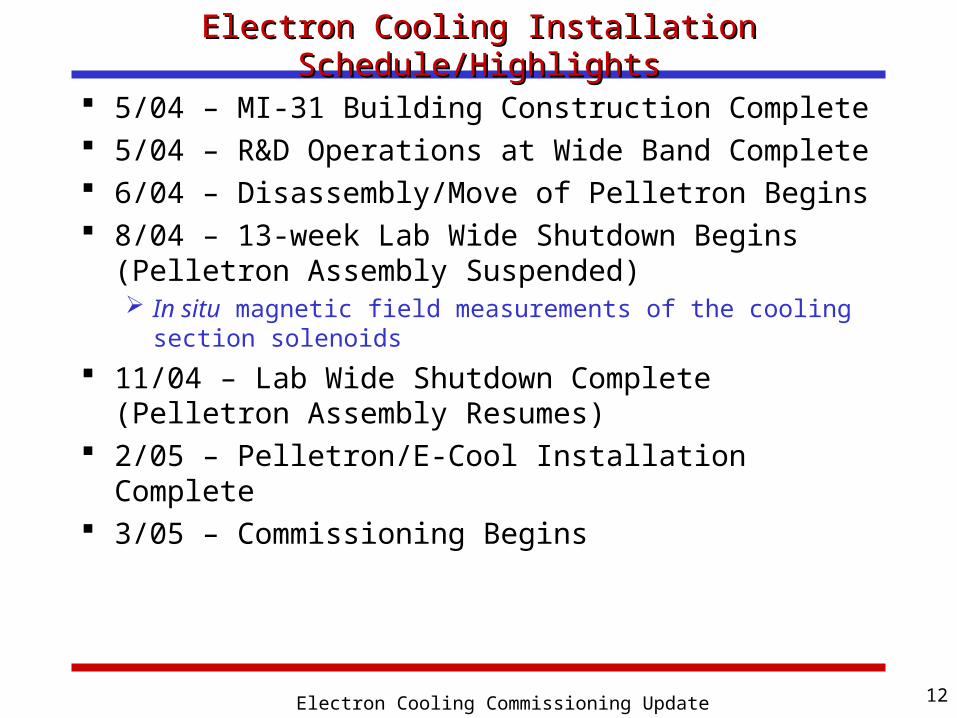
Electron Cooling Installation Schedule/HighlightsElectron Cooling Installation Schedule/Highlights
5/04 – MI-31 Building Construction Complete 5/04 – R&D Operations at Wide Band Complete 6/04 – Disassembly/Move of Pelletron Begins 8/04 – 13-week Lab Wide Shutdown Begins
(Pelletron Assembly Suspended) In situ magnetic field measurements of the cooling
section solenoids
11/04 – Lab Wide Shutdown Complete(Pelletron Assembly Resumes)
2/05 – Pelletron/E-Cool Installation Complete 3/05 – Commissioning Begins

Electron Cooling Commissioning Update 13
Electron cooling system setup at MI-30/31Electron cooling system setup at MI-30/31
Added section (includes
additional pumping)
Beam line accommodates both U-bend and vertical bend magnets
Fast acting valves
Magnetically shielded to protect e beam from fields imposed by the MI bus
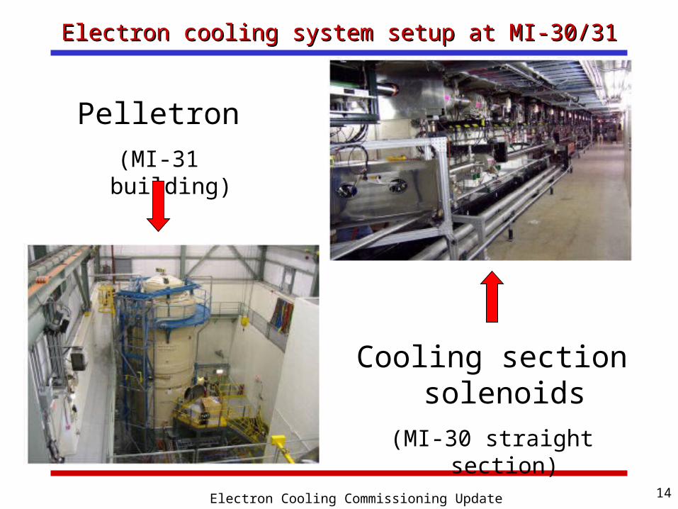
Electron Cooling Commissioning Update 14
Electron cooling system setup at MI-30/31Electron cooling system setup at MI-30/31
Pelletron(MI-31 building)
Cooling section solenoids
(MI-30 straight section)

Electron Cooling Commissioning Update 15
Mechanical oscillations of the PelletronMechanical oscillations of the Pelletron
Mechanical vibrations in the Pelletron were greatly reduced between the Wide Band assembly and the current assembly at MI-31
May help reduce beam motion in accel/deccel tubes May help HV stability (i.e. avoid full discharges)
0 10 20 30 40 50 601E-3
0.01
0.1
1
CPO sum
Am
plit
ud
e,
rel.
un
its
Frequency, Hz
MI-31 assemblyWide Band lab assembly
Peak @ ~ 3 Hz: Chain transverse oscillations
Peak @ ~ 30 Hz: Rotating shaft
Electron Cooling Commissioning Update 16
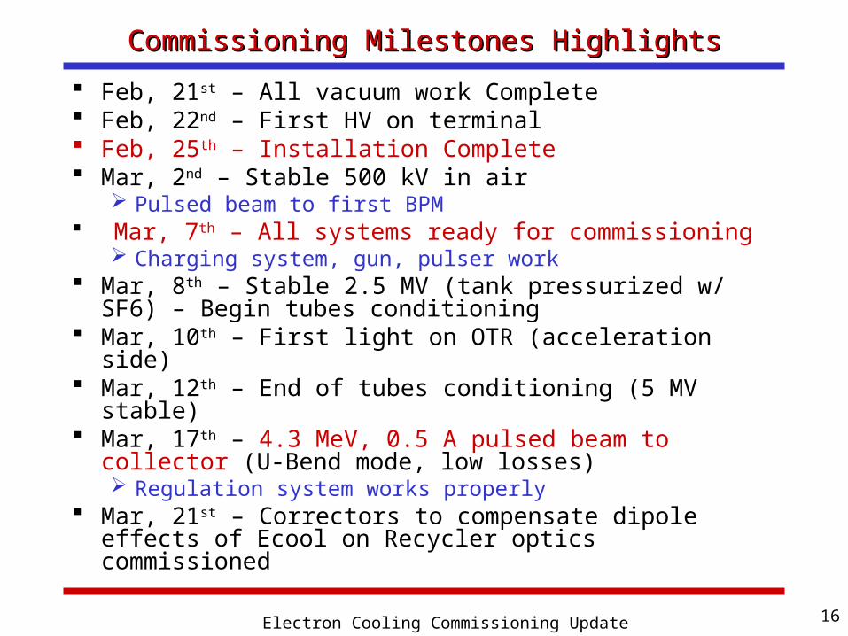
Commissioning Milestones HighlightsCommissioning Milestones Highlights
Feb, 21st – All vacuum work Complete Feb, 22nd – First HV on terminal Feb, 25th – Installation Complete Mar, 2nd – Stable 500 kV in air
Pulsed beam to first BPM Mar, 7th – All systems ready for commissioning
Charging system, gun, pulser work Mar, 8th – Stable 2.5 MV (tank pressurized w/ SF6) –
Begin tubes conditioning Mar, 10th – First light on OTR (acceleration side) Mar, 12th – End of tubes conditioning (5 MV stable) Mar, 17th – 4.3 MeV, 0.5 A pulsed beam to collector
(U-Bend mode, low losses) Regulation system works properly
Mar, 21st – Correctors to compensate dipole effects of Ecool on Recycler optics commissioned

Electron Cooling Commissioning Update 17
Commissioning Milestones Highlights (cont’)Commissioning Milestones Highlights (cont’)
Mar, 27th – 4.3 MeV, 50 mA pulsed beam through cooling section Correctors settings very different from calculations
based on magnetic measurements Mar, 28th – Apr, 5th: Shutdown (Pelletron tank
opened) Charging circuitry fixed Updated gun lens power supply Removed hard-wired -5 kV: Ready for DC beam
Apr, 7th – 4.3 MeV, 35 mA DC beam to collector (U-Bend mode)
Apr, 12th – Low intensity, 4.3 MeV pulsed beam to collector (full line) Protection systems commissioned with pulsed beam
Apr, 20th – First DC beam (few mA) in Recycler beam line
Apr, 27th – 4.3 MeV, 350 mA pulsed beam to collector (full line) Correctors settings based on magnetic measurements

Electron Cooling Commissioning Update 18
Commissioning Milestones Highlights (cont’)Commissioning Milestones Highlights (cont’)
May 3rd – 4.5 MeV, 750 mA DC beam to collector (U-Bend) Low magnetic flux configuration Preparation for ‘long run’… … but full discharge occurrences increase
May 4th – First beam size measurements in cooling section (pulsed beam) Recycler empty

Electron Cooling Commissioning Update 19
Tubes conditioningTubes conditioning
Pelletron is divided into 6 sections Each section was conditioned to 1.2 MV All sections together were conditioned to 5 MV (the
operation voltage is 4.32 MV)
Conditioning took 5 days (elapsed time) Detail for individual sections:
Other info: First vacuum activity began at 0.55 – 0.75 MV for individual
sections A Java Final State Machine was used for conditioning Conditioning was interrupted several times for some beam
related studies at low energy
Section # 1 2 3 4 5 6 Time, h 8 5 4.5 5 5 8

Electron Cooling Commissioning Update 20
Tubes conditioning - Sections 1-3 (example)Tubes conditioning - Sections 1-3 (example)

Electron Cooling Commissioning Update 21
High Voltage StabilityHigh Voltage Stability Reliable operation at 4.3 MV
Partly due to added section Wide Band vs MI-31
Pulsed beam, 3 hours:Multiple discharges
Pulsed and DC beam, 6 hours: No discharge
Intentional
Pulsed beam

Electron Cooling Commissioning Update 22
Protection systemProtection system Fast acting valves between Pelletron and Recycler ring (on
Supply and Return lines) Activated if pressure rises on the Pelletron side (as a result of
a full discharge for instance) Monitor several dozen signals with the Pelleron Mode
Controller (Java Application) Signals include:
- All BLMs- Capacitive pickups (CPOs) (e.g.: for terminal voltage
discharges) When one channel is ‘out of tolerance’
- Gun is closed (i.e. beam extraction is interrupted)- Trip flag is up (need operator to reset before re-establishing
beam)- All signal waveforms are saved in the buffer (512 ms long
over a time window that includes the trip)
Both the Fast acting valves’ logic and the Pelletron Mode Controller were tested Improvements were made (increase response speed, more
devices recorded, adjusted limits,…)

Electron Cooling Commissioning Update 23
Protection system (cont’)Protection system (cont’) To avoid full discharges and/or damaging the tubes , it is
important to shut off the gun as fast as possible Right now, it takes about ~1 ms to close the gun after the beam
permit has been taken off Faster circuit will be installed during next shutdown
Yellow:Fast CPO
Cyan:Beam permit
White:Cathode current transformer
~1 ms
Gun closes
Permit removed

Electron Cooling Commissioning Update 24
DiagnosticsDiagnostics
YAG crystal, OTR monitors throughout the beam line Beam size (shape), distribution Used to compare to optics models
1 multi-wire scanner Beam size and shape after 180° bend
Removable apertures in the cooling section Between each of the ten cooling section solenoid Beam size and angle
BPMs Between each of the ten cooling section solenoid + 16 in
other beam lines (accel, supply, return, transfer, decel) Can measure both pulsed and DC beam Capable of monitoring both electrons AND pbars

Arden Warner, AD/Recycler/Electron Cooling
OTR Detectors for the Medium Energy Electron OTR Detectors for the Medium Energy Electron Cooler Cooler
Detector characteristics 5 µm foil Lower current limit 20mA Resolution 50 µm
Applications Real-time charge density
distribution and beam size measurements
Measurement of beam initial conditions in the acceleration section
Beam ellipticity measurements Beam temperature measurements
with pepper-pot100 200 300 400 500 600
0
50
100
150
200
Upulse
=4.7 kV
Y A
xis
Titl
e
Y, pix.
B: SPA06=5.8 A D: SPA06=9.8 A F: SPA06=11.8 A H: SPA06=13.8 A J: SPA06=15.8 A L: SPA06=17.8 A N: SPA06=19.8 A
Beam Image from OTR at full current (acceleration tube exit)
Beam profile versus Lens current on acceleration side

Electron Cooling Commissioning Update 26
Recirculation in U-Bend mode – Short runRecirculation in U-Bend mode – Short run
700 mA DC beam re-circulating with low losses (5-10 minutes without discharges)
Green:Bias current
Cyan:Collector pressure
Blue:Acceleration tube current
Red:Needle current
Relative current loss at 0.5 A: ~6e-6

Electron Cooling Commissioning Update 27
Beam in cooling section (i.e. in Recycler ring)Beam in cooling section (i.e. in Recycler ring)
Pulsed beam transported through the full line with low loss and low ‘spatial oscillations’ in cooling section Correctors settings in cooling section based on magnetic
measurements made in-situ during installation
Cooling section
Horizontal displacement
Vertical displacement
BPM intensities(correspond to ~50 mA)

Electron Cooling Commissioning Update 28
Optics measurementsOptics measurements Understanding the beam line’s optics (supply line in
particular) is primordial in order to gain the beam envelope control necessary to achieve cooling
Principle: Differential trajectories measurements (good for linear optics only)
Method:- Take reference orbit- Apply kick and measure betatron motion of the beam- Repeat 4 times (+ ‘energy kick’ for dispersion)- Check reference orbit
Preliminary measurements: Determine that all lenses and correctors are hooked up
correctly and/or identify problems Exercise/commission differential orbit measurement
programs Calibration of power supplies Help achieving clean transport of the beam

Electron Cooling Commissioning Update 29
Supply line optics: Data vs OptiMSupply line optics: Data vs OptiM
After various problems were found and fixed, and several iterations for calibration purposes, measurements (with pulsed beam) are mostly consistent with OptiM calculations
400
Fri Apr 22 16:36:22 2005 OptiM - MAIN: - Y:\MI-31\Shifts\2005\05Apr13\PM\MI30_Gold_ALEXEY.opt
2-2Co
ord
ina
tes
X&
Y[c
m]
X Y
400
Fri Apr 22 16:44:15 2005 OptiM - MAIN: - Y:\MI-31\Shifts\2005\05Apr13\PM\MI30_Gold_ALEXEY.opt
1.4
-1.5
Co
ord
ina
tes
X&
Y[c
m]
X Y
Supply line

Electron Cooling Commissioning Update 30
Preliminary energy measurementsPreliminary energy measurements
For cooling, the electron beam and pbar bunches energies need to be ‘aligned’, thus measuring the electron beam absolute energy is critical (<0.3 %)
Principle: Measure the Larmor frequency of the beam oscillations in the cooling section solenoid (via differential trajectories measurements)
So far, measurements indicate that the energy is lower than expected by ~3% Correlated by
‘optimum’ bends settings found
Awaits more precise measurements with DC beam

Electron Cooling Commissioning Update 31
Preliminary total angles Preliminary total angles
Except for dipole offsets, no attempts were made to minimize the angles (at this stage)
Component Upper limit, rad
Measured by Achieved, rad
Temperature 90 Pepper pot + YAG/ OTR
No data
Aberration 90 Pepper pot + YAG/ OTR; BPM responses
No data
Envelope scalloping
100 Movable orifices ~1000 @ 0.4A pulsed
Dipole offsets
100 BPMs ~ 300
Beam motion 50 BPMs ~100 Drift velocity 20 Calculated Total 200 ~ 1000

Electron Cooling Commissioning Update 32
DC beam commissioning in the full line Beam line optics
• Needs to be analyzed and adjusted to establish design beam size and rms angular spread
Energy stability• Energy fluctuation is estimated by analysis of a BPM signal
from a high- dispersion region Establish 0.5 A DC beam
Observe electron cooling The energies are aligned within 0.3 % Effect of electron cooling
is observed by longitudinal Schottky monitor
What’s next ?What’s next ?

Electron Cooling Commissioning Update 33
Interference with the Recycler’s work for Interference with the Recycler’s work for luminosityluminosity
Effects of ECool bends and cooling section field on the pbar dynamics in RR- Corrected and tested
Effects of the e–beam space charge on pbar dynamics in RR- supposed to be negligible
Changes in the pbar lifetime caused by a pressure rise in the cooling section- is negligible according to measurements in
WB. Also, fast isolation valves installed and tested
Drag force- many e- beam measurements can be done either at low electron currents or at the electron energy shifted by 1%
Measurements of DC beam dimensions in CS and measurements with the YAG/OTR downstream of the cooling section- no pbars in RR
If above is correct, the electron cooling tune-up may be done with Recycler being emptied between the TeV shots and pbar shots from the Accumulator

Electron Cooling Commissioning Update 34
Some Remaining Outstanding IssuesSome Remaining Outstanding Issues
Recirculation for long runs (i.e. hours) is not established Full discharges cannot be prevented (so far)
Main injector beam loss trips our loss monitors Temporary fix: increase protection system limits
but… … beat the purpose Need MI people to work on reducing losses and/or
additional shielding
OTR cameras in MI-30 tunnel damaged by radiation
Beam motion with MI ramps Prevents recirculation high intensity beam Additional magnetic shielding will be installed

Electron Cooling Commissioning Update 35
MI losses (mostly detected on the return line)MI losses (mostly detected on the return line)
Losses appear to be related to slip stacking First attempts to reduce them were not successful
Green:C90 loss monitor
Red:R06 loss monitor
Blue:R04 loss monitor
Cyan:MI beam current
Original trip level for DC beam operation

Electron Cooling Commissioning Update 36
MI ramp induced beam motionMI ramp induced beam motion
Stray fields from the MI bus and/or QCL alter the beam orbit in the return line (mostly) Induces losses downstream
Beam loss spikes on the QCL negative slope
1 Hz repetition rate (random w.r.t. MI ramp)

Electron Cooling Commissioning Update 37
SummarySummary
Achieved stable high voltage regulation (with beam) at designed Pelletron energy (4.3 MV)
Achieved DC electron beam in the Recycler beam line (35 mA)
Achieved ‘stable’ (i.e. minutes) high intensity (i.e. 750 mA) DC beam in U-Bend mode
Implemented and tested (in U-Bend mode) all protection systems
Interference with Recycler operation was minimal Will increase now
Although the commissioning started later than originally planned, we still expect to observe cooling of pbar by September 8, 2005.