Embed Size (px)
Citation preview

Electroni cs Woriá JUNE, 1967
60 CENTS
OCCUPATIONAL OUTLOOK FOR ELECTRONICS TECHNICIANS
EMERGENCY HIGHWAY RADIO-Which System?
COMMON -SENSE DESIGN OF TRANSISTOR AMPLIFIERS
SEMICONDUCTOR SWITCHING OF LOW -POWER CIRCUITS
FLUID !PLIFIERS
www.americanradiohistory.com

New hi -fi rectangular RCA "Permachrome" color tube with 295 sq. inch viewing area, and built -in face protection New rare earth phosphors for brighter pictures, livelier colors 27 tube, 10 diode, 1 transistor circuit 25,000 volt regulated picture power Automatic degaussing & mobile degaussing coil Exclusive built -in self- servicing aids Dynamic pincushioning correction circuit eliminates picture edge distortion Extra B+ boost for improved picture definition 3 -stage video IF strip reduces interference, improves reception Exclusive Heath "Magna-Shield" improves color purity Gated Automatic Gain Control (AGC) for steady, flutter -free pictures even under adverse conditions such as airplane traffic Automatic Co /or Control circuit reduces color fading Deluxe VHF turret tuner with "memory" fine tuning & long- life nickel silver contacts 2 -speed transistor UHF tuner for both fast station selection and fine tuning individual channels Two hi -fi sound outputs ... a cathode follower for play thru your
Deluxe
Heathkif "295"
Color TV...
x47995
hi -fi system, and an 8 ohm output for connection to special contained -field 6" x 9" speaker (included) Two VHF antenna inputs ... a 300 ohm balanced and 75 ohm coax to reduce interference in metropolitan or CATV areas Circuit breaker protection 1 -year warranty on picture tube, 90 days on all other parts Tubes alone list at over $277 Liberal credit terms available - details in FREE catalog
Kit GR -295, all parts including chassis, tubes, mask, UHF & VHF tuners, mounting kit and special extended -range 6" x 9" speaker, 131 lbs. (REA or motor freight only) . $479.95 GR -295 SPECIFICATIONS - Picture she: Rectangular viewing area approx. 295 sq. inches, (23' diagonally, 20' horizontal, 16' vertical). Tube Size: 25' overall diagonal measurement. Deflection: Magnetic 90 °. Focus: Electrostatic. Convergence: Magnetic. Antenna input impedance: 300 ohm balanced, or 75 ohm unbalanced (VHF). Picture IF carrier frequency: 45.75 MHz. Sound IF carrier frequency: 41.25 MHz. Color subcarrier: 42.17 MHz. Video IF bandpass: 3.58 MHz. Sound IF frequency: 4.5 MHz. Tuning range: VHF channels 2 -13, UHF channels 14 -82. Sound cathode follower: Output impedance; 3 K. Frequency response; =1 db, 50- 15,000 Hz. Harmonic distortion, less than 1%. Output voltage; 2 v. Audio output: Output impedance, 8 ohms. Output power, 2 watts. Frequency response, =2 db, 50- 10,000 Hz. Harmonic distortion, less than 3 %. Power requirements: 110 -130 v., 60 Hertz AC, 330 watts. Wall mounting: 20' D x 21' H x 26" W inside. Control panel assembly, 61/2" W x 7 7/r" H x 7' D.
Install In A Wall Or These Assembled Heath Cabinets
Contemporary Styled Walnut Cabinet Factory assembled of fine veneers and solids with oil- rubbed walnut finish. GR -295 speaker and con- vergence panel mount behind tilt -out grille cloth on right side. A slim 19" D x 31" H x 34%" W. Assembled G RA-295-1, 56 lbs. (Express or motor freight) $62.95
Contemporary Styled Deluxe TV Cabinet Constructed of the finest veneers and solids. G Ft -295 speaker and convergence panel mount behind speaker grille cloth on right side. Measures 19'4" D x 33 %" H x 41" W. Walnut finish. Assembled GRA- 295 -2, 65 lbs. (Express or motor freight) $94.50
Deluxe Early American TV Cabinet Made of a special combination of veneers and solids
. all beautifully finished in popular salem- maple. GR -295 speaker and convergence panel mount behind grille cloth on right side. Measures 19 %" D x31 "Hx36 "W. Assembled GRA- 295 -3, 67 lbs. (Express or motor freight) $99.95
www.americanradiohistory.com

Hi -fi rectangular color tube with 180 sq. inch viewing area and anti -glare safety glass
Rare earth phosphors for brighter, livelier colors Extra B + boost and smaller dot size for imprcved picture definition 27 tube, 10 diode, 1 transistor circuit 24,000 volt regulated picture power Exclusive built -in self- servicing facilities Exclusive Heath "Magna-Shield" improves color purity Automatic degaussing Automatic Color Control circuit to reduce color fading Gated Automatic Gain Control (AGC) fcr steady, flutter -free pictures even under adverse conditions such as airplane traffic 2 -speed transistor UHF tuner for both fast station selection and fine tuning individual channels Deluxe VHF turret tuner with "memory" fine tuning and long -life nickel silver contacts 3 -stage video IF strip reduces interference, improves reception Two hi -fi sound outputs ... a cathode follower for play thru your hi -fi system, and an 8 ohm output for connection to special limited -field 4" x 6" speaker (included)
Deluxe
Heathkit®
"180"
Color TV...
x37995
Two VHF antenna inputs ... a 300 ohm balanced, and a 75 ohm coax to reduce interference in metropolitan or CATV areas Circuit breaker protection 1 -year warranty on picture tube, 90 days on all other parts Tubes alone list at over $245 Liberal credit terms available - details in FREE catalog.
Kit GR -180, all parts including chassis, tubes, mask, UHF & VHF tuners, mounting kit, and special limited -field 4" x 6" speaker, 102 lbs. (REA or motor freight only) $379.95
GR -180 SPECIFICATIONS - Picture size: Rectangular viewing area approx. 180 square
inches (18' diagonally, 16' horizontally, 12' vertically). Tube Size: 19' overall diagonal meas-
urement. Deflection: Magnetic 90 °. Focus: Electrostatic. Convergence: Magnetic and Dy-
namic. Antenna input impedance: 300 ohm balanced, 75 ohm unbalanced VHF. Picture IF
carrier frequency: 45.75 Meg. Hz. Sound IF carrier frequency: 41.25 Meg. Hz. Color sub - carrier frequency: 42.17 Meg. Hz. Video IF bandpass frequency: 3.58 Meg. Hz. Sound IF
frequency: 4.5 Meg. Hz. Tuning range: VHF channels 2 -13, UHF channels 14 -83. Sound cathode follower; Output impedance 3K ohm, frequency response .1 db, 50- 15,000 Hz. Harmonic
distortion less than 1%, output voltage 2V. Audio output: Output impedance, 8 ohms. Output
power, 2 watts; Frequency response, w2db, 50- 10,000 Hz. Harmonic distortion less than 3%. Power requirements: 110 -130 V., 60 Hz AC, 330 watts. Wall mounting (mask): 159Áw" H
x 24s/µ' W. Chassis room: 17%' H x 26' W x 18' D (This is with %' clearance on both sides
and the top).
Install In A Wall Or Either Assembled Heath Cabinets
Contemporary Walnut Cabinet Factory assembled of beautiful solids and veneers with an oil- rubbed walnut finish. The GR -180 speaker is mounted behind right side of one -piece picture -control panel mask. Measures a compact 18'' /u "Dx28'/< "Wx29 "H. Assembled GRA- 180 -1, 41 lbs. (REA or motor freight) $49.95
Deluxe Early American Cabinet Factory assembled with a special combination of veneers and solids, finished in popular Salem - Maple. GR -180 speaker mounts on right side of one -piece face mask. Measures 18/u" D x 28 %" W x31%" H. Assembled GRA -180 -2, 48 lbs. (REA or motor freight) . $75.00
www.americanradiohistory.com

Regardless
Of What You Pay For COLOn
It Can't Perform
As Well As These
Two HEATHI' Models...
www.americanradiohistory.com

Exclusive Features That Can't Be Bought In Ready -Made Sets At Any Price!
All color TV sets re- quire periodic con - %ergence and color purity adjustments. Both Heathkit color IV's have exclu-
sive built -in servic- ing aids, so you can perform these ad-
justments any time . . . without calling in a
TV serviceman ... without :my special skills or knowledge. Just flip a switch on the built -in dot generator and a dot pattern appears on the screen. Simple -to- follow instructions and detailed color photos in the manual show you exactly what to look for, shat to do and how to do it. Results:' Beautifully dean and sharp color pictures day in and day out . and up to S200 savings in service calls through- out the life of your set. No other brand of color TV has this money -saving self -servicing feature!
Vertical Swing -Out Chassis!
All parts mount on a single one-piece chassis that's hinged to make it more accessible for casier construction, care are installation.
Exclusive Heath Magna -Shield!
This unique metal shield surround, the entire picture tube to help keep out stray esternal magnetic fields and improve color purity. In addition Automatic Degaussing demagnetizes and "cleans" the picture every time you turn the set on from a "cold" start ... also permits you to nose the set about freely without any manual degaussing. A mobile degaussing coil is included for initial set -up.
Convergence Control
Board
. . . for fast, easy dynamic convergence and gray scale adjustments any time you decide color purity needs it. If you install the GR -295 model in any of the 3 optional cabinets, this board is mounted behind the special "tilt -out" speaker grille section. If you install the GR -180 model in any of its optional cabinets, the board can be temporarily mounted on the bottom of the cabinet underneath the tube face when making adjustments. In either case, there's no awkward reaching around the back of the set, or mirrors to set up. In addition, the GR -295 has a Universal .Main Control Panel that can be mounted at the bottom, top or right side of the picture tube for more flexible in -wall installation.
Here's Why! Your Choice Of Installation!
Another Heathkit exclusive! Both color TV's are de- signed for mount- ing in a will or your own custom cabinet. Or you can install either set in a choice of factory assembled and finished Heath contemporary walnut or Early American cabinets (see opposite fold- out).
From Parts To Programs In Just 25 Hours!
MM.
And no special skills or knowledge needed. All critical circuits (VHF and UHF tuners, 3 -stage IF assembly and high voltage power supply) are prebuilt, aligned and tested at the factory. The assembly manual guides you the rest of the way ssith simple, non- technical in- structions and giant pictorials. It's like having a master teacher at your elbow pointing out every step of the way. You can't miss.
- - -- -Order Now - Use This Form -- i
HEATHKIT 1967 FREE! World's Largest Electronic Kit
Catalog! Describes these and over 250 kits for stereo /hi -fi, color TV, amateur radio, shortwave, test, CB, marine, educational, home and hobby. Save up to 50% by doing the easy assembly yourself. Mail coupon or write Heath Company, Benton Harbor, Michigan 49022
HEATH COMPANY, Dept. 15 -6
Benton Harbor, Michigan 49022
J Enclosed is $
Please send model (s).
I _, Please send FREE Heathkit Catalog.
But Don't Take Our Word For lt. Read What The Experts And Owners Say! Hubert Luckett, Executive Editor, Popular Science Magazine: "Building your own color TV front a kit is not as outrageously imprac- tical as you might suppose. For those who tremble at the thought of tackling something so Jiurtastically complicated, let me encourage you with a borrower! quote: 'The only tying you have to fear is fear itself' " "The second most impressive thing about the kit is the instruction manual (the most impres- sive thing is the viewing quality of the color picture). If you can read and understand ordi- nary English, the manual is like having a master teacher at your elbow pointing out every step."
the circuitry, features and performance match or exceed those of sets selling at twice the price. Some of the features, such as the built -in servicing aids, can't he bought in ready- made sets at any price." "With the instructions supplied, your experi- ence in assembling the kit, and the self -servicing features built -in, you'll be able to do most servicing yourself" John Drummond, Technical Editor, Popular Electronics Magazine: "... we simply bud to know how well a 25 hours -to -build color TV kit would stuck up against the more expensive, well-advertised wired sets people are gobbling up. It didn't take us long to find out that the Heath GR -295 compares favorably with the best (i/ them." Radio -TV Experimenter Magazine, Oct -Nov. '66: "Over the File of a color set, repair and service call costs can exceed 5200. Brat, build the color set yourself and you will save several hundred dollars in repairs plus wind up with better color as you'll align the color reception to what yohu - not a serviceman - thinks is good to look at." Robert F. Scott, Radio -Electronics Magazine: "Friends who've seen my Heathkit GR -295 generally ask, ' Why can't I get a good picture like that on my color set ?' Audio Magazine, May '66: "... sets similar in appearance seem to run around $700, with- out the built -in service features like the dot generator. Add to this the saving in service costs which the average set world require, since the builder wool(/ undoubtedly service his own set throughout its life, and the Heathkit GR-295 is a real bargain." "Besides that, it is capable of a great picture". Mr. Robert D. Ta)ior, Sacramento, Calif.:
. . it's the best TV on the market, nothing compares with it (I have been looking at and checking TV's over 2 rears). The manual (.service) is a 'gold mine' of savings." Mr. C. A. Petrarca, West Caldwell, N. J.: "We are still getting oohs, alrhs, 'best I've ever seen', 'how bright the colors are', etc. from our friends and neighbors." Mrs. Joseph Gesswein, Bethesda, Md.: "If a housewife with 3 children under 4 years old can successfully build it in her few spare moments, it has to be good."
Name
Address
City
. plus shipping.
_State Zip Prices 8 specifications subject to change without notice. CL -281
L J CIRCLE NO. 108 ON READER SERVICE CARD
June, 1967
www.americanradiohistory.com
Start here:
irdr
11111111,
LL«IL l' p
MIETUtiAT ROO TIIA IASB
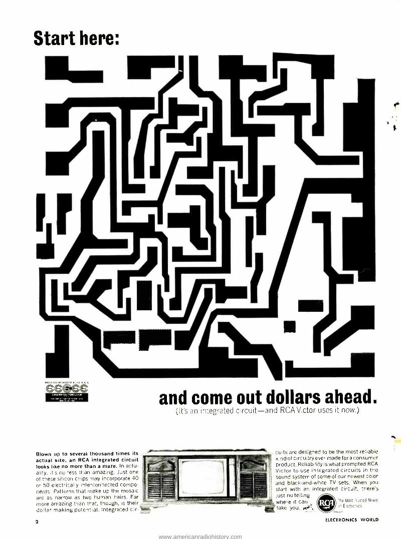
Blown up to several thousand times its actual size, an RCA integrated circuit looks like no more than a maze. In actu- ality, it's no less than amazing. Just one of these silicon chips may incorporate 40 or 50 electrically interconnected compo- nents. Patterns that make up the mosaic are as narrow as two human hairs. Far more amazing than that, though, is their, dollar- making potential. Integrated cir-
and come out dollars ahead. (Ifs an integrated circuit -mnd RCA Victor uses it now.)
2
cuits are designed to be the most reliable kind of circuitry ever made for a consumer product. Reliability is what prompted RCA
Victor to use integrated circuits in the sound system of some of our newest color and black- and -white TV sets. When you start with an integrated circuit, there's just no telling where it can take you. tai.
The Most Trusted Name
In Electronics
ELECTRONICS WORLD
www.americanradiohistory.com
EIeel ron ies 11( rltl
THIS MONTH'S COVER is tied in with our lead story on "Fluidic Systems." We have interconnected a num- b r of fluidic -system com- ponents manufactured by Corning Glass Works. Nor- mally the clear plastic tub -
ing carries air under pres- sure from one component to another. We have taken a little artistic license, hiwever, and have filled the tubing with water of various colors in order to more effectively dramatize the importance of this relatively new technology. Though these components cannot match the speed of e'ectronic control systems, they have the advantages of simplicity and high re- liability for a good many important applications . . .
Photo: Louis Mervar.
l'ahli.claer PHILLIP T. HEFFERNAN
Editor WM. A. STOCKLIN
re, finical Editor MILTON S. SNITZER
Is.curvaf< /',rlilnr.s LESLIE SOLOMON
P. B. HOEFER
.Issistant Editor MARSHA JACOBS
Contributing Editors WALTER H. BUCHSBAUM
Prof. ARTHUR H. SEIDMAN -I,t ','dilur
HERBERT L. SILBERMANN I ri ,uul I), 'i, i, Dept.
J. A. GOLANEK Irlrrrvisia Sah's Abina ter
LAWRENCE SPORN Idrerti.einr .' errice ,4lorloger
ARDYS C. MORAN
June, 1967
Electronics World CONTENTS
23 Fluidic Systems C. 1. nninrr
Components using air flow can be made to sense, count, amplify, and control. Although far slower than their electronic counterparts, fluidic devices are vibration- and explosion -proof, are not affected by radiation, heat, or r.f.
26 Measuring Tracking Ability of Phono Cartridges 1. H. Koyrn
29 LSA Diodes: New Source of Microwave Power Discovery of a new mode of oscillation in gallium arsenide diodes permits design of solid -state oscillators capable of delivering 20 mW at 88 GHz.
30
32
33
Recent Developments in Electronics
Loudspeakers for Electronic Musical Instruments Karl Kromer
Semiconductor Switching of Low -Power Circuits Aubrey Harris
Transistors can be used to switch d.c. loads up to 35 amperes and a.c. loads up to 10 amperes, with no contact bounce, reduced noise, and economy of space.
36 The Penultimate Automatic Keyer P. A. Stork, S. Gordon & A. Monlr.donio
39 The Search for a Highway Emergency Radio Program Rohner M. Brown
Many methods have been proposed to assist the motorist either in an emergency, or to give traffic routing directions. Most use some form of CB, and some include very sophisticated electronic equipment. Here are details on several of these systems including HELP, REACT, CRW, RRA, and DAIR and covers their good and bad points.
43 46 48
The Laser Interferometer I. P. Enyemon
Ferrite Coil and Crystal Sideband Filter Richard A. Genoiue
Common -Sense Design of Transistor Amplifiers Donald L. Carlson
Straightforward method of using Ohm's Law plus simple formulas to calculate values of bias network and load resistors needed in a stage of r.f. or a.f. amplification.
64 Occupational Outlook for Electronics Technicians
14
54
76
EW Lab Tested Dynaco Stereo 120 Power Amplifier Jensen X -40 and X -45 Speaker Systems
Magnetic Shielding John Frye
Test Equipment Product Report "Knight -Kit" KG -2100 Laboratory Oscilloscope Hickok Model GC -660 Color -Bar Generator Sensi- Tronics Model 200 Electronic Circuit Breaker
MONTHLY FEATURES 4 Coming Next Month 60 Radio & TV News
12 Letters from Our Readers 82 Book Reviews
c` / ' New Products & Literature
Electronics World: Published monthly by Ziff-Davis Publishing Company at 307 North Michigan Ave.. Chicago. Illinois 60601. One year subscription $6.00. Second Class Postage paid at Chicago, Illinois and at additional mailing offices. Subscription service: Portland Place. Boulder. Colorado 50302. Copyright Ç) 1967 uy Ziff -Davis Publishing company. All rights reserved.
3
www.americanradiohistory.com
It will actually take you
longer to read this
advertisement than to
install this new
"Quick Grip" mobile
antenna mount. No h
to drill. Cable is
completely hidde
Makes the world's
finest antennas the
world's most Tact.
Practically every A/S mobile CB antenna made may be ordered with a "Quick - Grip" mount, including all versions of the mighty Maggie Mobiles.
Model M -176, illustrated above. M -175, same coil and whip less spring. M -177 is "Quick -Grip" version of our great 18" Mighty -Mite. Mount only also available.
the antenna
specialists co. division of Anzac
Industries, Inc.
12435 Euclid Ave., Cleveland, Ohio 44106
Export: 64.14 Woodside Ave., "Stripes of Quality" Woodside, N.Y. 11377 111)
CIRCLE NO. 124 ON READER SERVICE CARD 4
COMING
NEXT MONTH
SPECIAL ISSUE:
TRANSISTORS
EItcliyiiiiesAtn'IEL. -
This 24 -page special section carries six feature articles covering various types of transistors
and their applications. T.J. Robe of RCA offers valuable tips for selecting r.f. transistors in
his article Small -Signal High -Frequency Transistors. Richard A. Stasior, manager of appli-
cation engineering for G -E's Semiconductor Products Dept., covers the audio field with
Small -Signal Low -Frequency Transistors. Diffused Transistors, including annular, mesa,
epitaxial, and interdigitated, are discussed by Jack Haenichen, manager of Thyristor Opera-
tions for Motorola, while Ronald W. Vahle of Delco offers practical guidelines for selecting
Power Transistors. Arthur D. Evans, vice -president and engineering manager of Siliconix,
discusses the various types of Field -Effect Transistors while Lloyd Walsh and Steve Fierro
of Fairchild Semiconductor cover Switching Transistors. Plus ... shorter articles on Selec-
tion oi Transistors by R.M. Ryder of Bell Labs and on Alloy Transistors.
STATIC ELECTRICITY The space age's 1)illion -r ¡ear -olrl gremlin has been responsible for accidentally fir- ing mi.ssilr'.Y, damaging .s( IIironrlueturs, and causing 1 aircraft explosions. L..:1.
Lacy explains 11(11) the danker is de- tected and then minimized.
ELECTRONIC CHALLENGES IN THE SST PROGRAM l'lt¡il j. faster than twice the spud of .sourd, and requiring close control of flight conditions for passenger safely und
comfort, the .SST will )Iced more soplris- tWuled und reliable electronics.
TROUBLESHOOTING INTEGRATED CIRCUITS Trouble ahead for the T1' technician? \1 ill he be able to service an all -IC color-T1' set' Here's what he'll hact' /0 lour). the approach he'll hare to take, and nec) lest -equipment techniques he'll hare to ir.sr la krep abreast of fittest tech - nology. 'this Trill be Prut I of an impor- tant two-part article.
All these and many prore interesting and inforaurlire articles will be yours in the July issue of I'LEC¡1/O','ICS 1t ONLI) . . . on sale fune 20th.
ZIFF -DAVIS PUBLISHING COMPANY Editorial and Executive Offices One Park Avenue New York, New York 10016 212 679.7200
NEW YORK OFFICE 212 679.7200 James J. Sullivan Joseph E. Halloran
MIDWESTERN OFFICE 307 North Michigan Avenue Chicago, Illinois 60601 312 726 -0892 Midwestern Advertising Manager, Royce Richard
WESTERN OFFICE 9025 Wilshire Boule+ard Beverly Hills, California 90211 213 CRestview 4 -0265; BRadshaw 2.1161 Western Advertising Manager, Bud Dean
William B. Ziff Chairman of the Board (194(.1953) William Ziff President W. Bradford Briggs Executive Vice President Hershel B. Sarbin Senior Vice President Philip Sine Financial Vice President Walter S. Mills, Jr. Vice President, Circulation Stanley R. Greenfield Vice President, Marketing Phillip T. Heffernan Vice President, Electronics Division Frank Pomerantz Vice President, Creative Services Arthur W. Butzow Vice President, Production Edward D. Muhlfeld Vice President, Aviation Division Irwin Robinson Vice President, Travel Division
Radio & TV News Radio News Radio -Electronic Engineering Trademarks Reg. U.S. Pat. Off. SUBSCRIPTION SERVICE: All subscription correspondence should be addressed to Electronics World, Circu- lation Department, Portland Place, Boulder, Colorado 80302. Please allow at least six weeks for change of address. Include your old address, as well as new -enclosing if possible an address label from a recent issue.
EDITORIAL CONTRIBUTIONS must be accompanied by return postage and will be handled with reasonable care; however publisher assumes no responsibility for return or safety of art work, photographs, or manuscripts. ELECTRONICS WORLD (June, 1967, Vol. 77, No. 61. Published monthly at 307 North Michigan Avenue, Chicago, Illinois 60601, by Ziff -Davis Publishing Company -also the publishers of Airline Management and Marketing, Boating, Business & Commercial Aviation, Car and Driver, Cycle, Flying, HiFi /Stereo Review, Modern Bride, Popular Aviation, Popular Electronics, Popular Photography. Skiing, Skiing Area News, and Skiing Trade News. (Travel Weekly is published by Robinson Publications, Inc.. a subsidiary of Ziff -Davis Publishing Company.) One year subscription rate for U.S., U.S. Possessions. and Canada, $6.00; all other countries. $7.00. Second Class postage paid at Chicago, Illinois and at additional mailing offices. Authorized as second class mail by the Post Office Department, Ottawa, Canada and for payment of postage in cash.
ELECTRONICS WORLD
JAPAN James Yogi Ishikawa Mansion =4, Sakuragaoka Shibuya ku, Tokyo 462- 2911 -3
CIRCULATION OFFICE Portland Place, Boulder, Colorado 80302
1,711171I or HICIi FIDELITY
e Member
Add Bureau of z Circulations
www.americanradiohistory.com
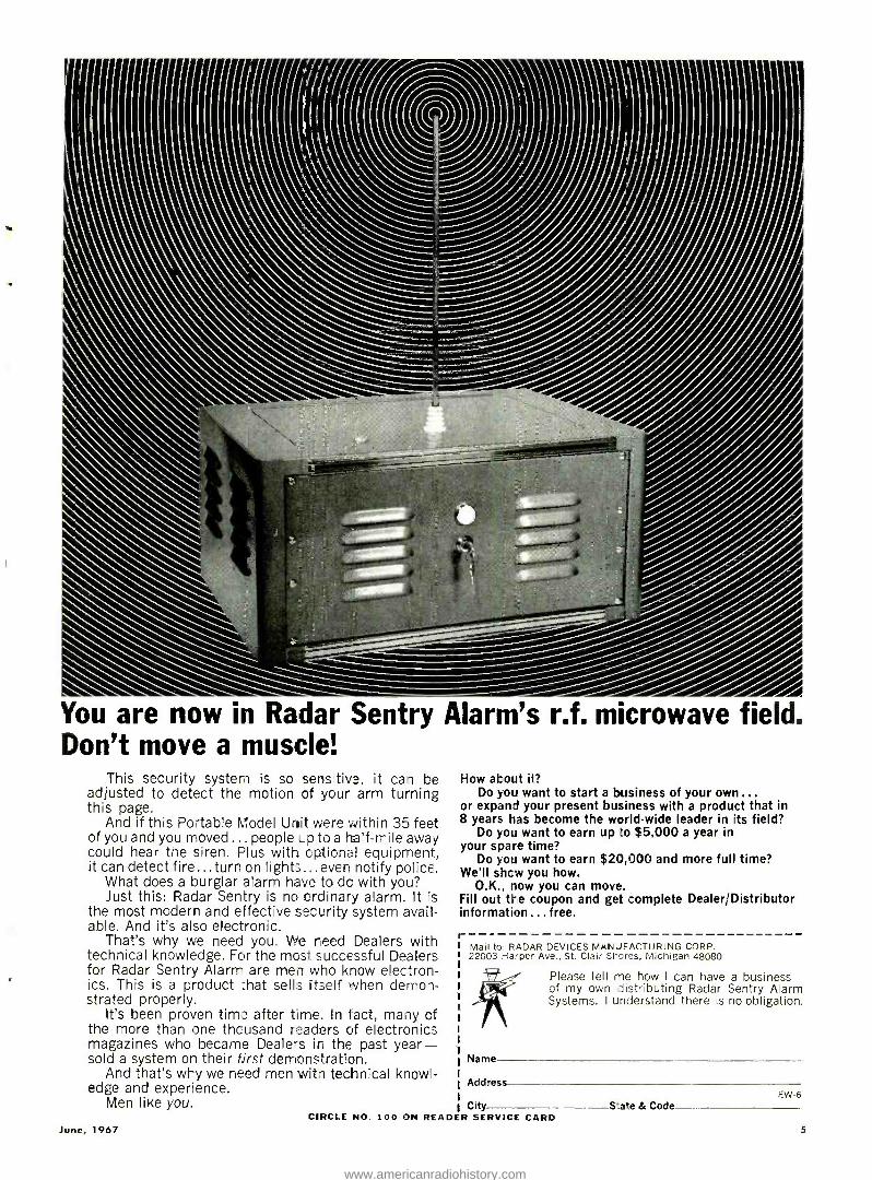
You are now in Radar Sentry Alarm's r.f. microwave field. Don't move a muscle!
This security system is so lens tive, it can be adjusted to detect the motion of your arm turning this page.
And if this Portable Model Unit were within 35 feet of you and you moved ... people ;.p to a half -mile away could hear the siren. Plus with optional equipment, it can detect fire...turn on lights. ,,. even notify police.
What does a burglar alarm have to do with you? Just this: Radar Sentry is no ordinary alarm. It is
the most mcdern and effective security system avail- able. And it's also electronic.
That's why we need you. We need Dealers with technical knowledge. For the most successful Dealers for Radar Sentry Alarm are men who know electron- ics. This is a product that sells itself when demon- strated properly.
It's been proven time after time. In fact, many of the more than one thousand readers of electronics magazines who became Dealers in the past year - sold a system on their first demonstration.
And that's why we need men with technical knowi- edge and experience.
Men like you.
June, 1967
How about ii? Do you want to start a business of your own...
or expand your present business with a product that in 8 years has become the world -wide leader in its field?
Do you want to earn up to $5,000 a year in your spare time?
Do you want to earn $20,000 and more full time? We'll show you how.
O.K., now you can move. Fill out the coupon and get complete Dealer; Distributor information ...free.
Mail to: RADAR DEVICES MANUFACTURING CORP. 22003 Harpes Ave., St. Clair Shores, Michigan 48080
Name
Address
City
Please tell me how I can have a business of my own dist- ibuting Radar Sentry Alarm Systems. I understand there is no obligation,
CIRCLE NO. 100 ON READER SERVICE CARD Sate & Code
EW-6
5
www.americanradiohistory.com
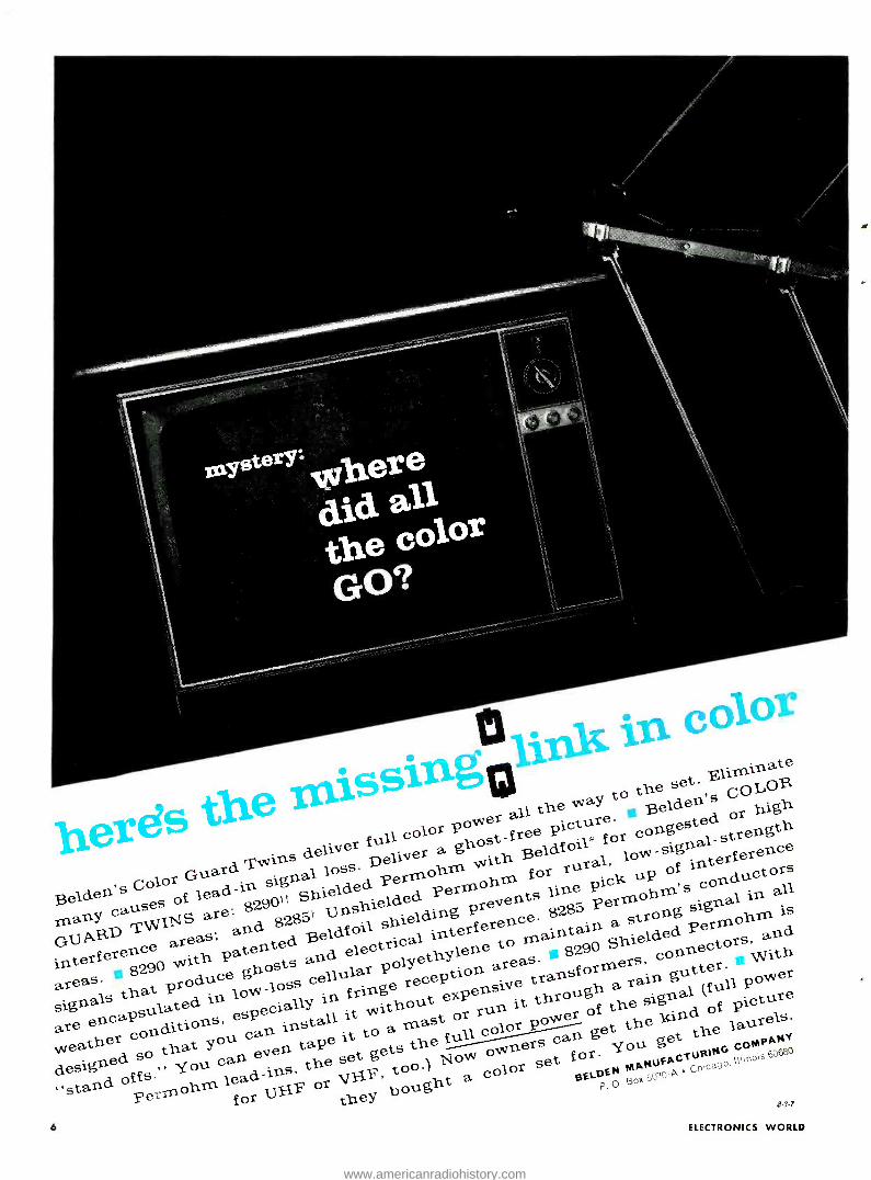
15 .n color írß ' urinate Sing he set. Ell COLOR, a to ri's CO hem
er the w Be1de
d or high t herds or P °w ictu este th er full col host -free picture.
il* congested.
-signal-strength Twins deli-ver Deliver
a g with Beldf o
rat, low ld
interference OLOR,
Color Guard nal loss. ermohm for ru uP of
conductors elders s lead-in. slg
Shielded. P
Pero-lob-1n line al, m's ° °rid all B of 829pfit S nshielded prevents 85 permoh in
many g are-. g285í Unshielded. ce 82 strong ohm is
GUARS TWINS areas; grid d
oils cal interfered maints P hielded Perm u and interference with patente and electrical to ß2g0 S connector
*With w hosts cellular
poly n areas ormets' areas. duce g cello cePt1O transf in gut owes ar is that Pr° in
especially in fringe re t expensive through ugh a rain nal Mull P re
signa ecial.s withou run it of the , c of picture
are ends
offs."
ton ou can inst-pel it to a Ynastfor color P° pan get the Butt e laurels.
weather S° that you. evert ta 0 set gets the ouvriers You +gAGTURINó
DDMP66V
dstárid °f f g Tmohm lead.-ins, tOr VgF,
bought a color gE1 DEÓ gox 5p10 A ch ca9
P. Pe for they 37
6 ELECTRONICS WORLD
www.americanradiohistory.com

J; .,r, 82 en Beldldeder
wlitl1 Belé$ted areas for COng
e r ec tle S2S5,
13.elden
LnEr'ef r r+ aareá .
Call your $elder d = ab t
e
C
June, 1967
*6,1,100n Poky. U, I Pdinf Office t Belk_n Palvnf No. 2,;6?,L,1 ttBelden PyUU No. 2,182,251 and Pal. Pending CIRCLE NO. 123 ON READER SERVICE CARD
7
www.americanradiohistory.com
DISCOVER THE EASE AND EXCITEMENT OF TRAINING AT HOME THE NRI WAY
New Achievement Kit - Custom Training Kits -"Bite Size" Texts
Only NRI offers you this pioneering method of simpli- fied "3 Dimensional" home -study training in Electron- ics, TV /Radio and Broadcasting /Communications. It's a remarkable teaching idea unlike anything you have ever encountered, the result of more than half a cen- tury of simplifying, organizing and dramatizing learn - ing -at -home techniques. If you are an ambitious man -regardless of your education -you can effectively learn the Electronics field of your choice the NRI way.
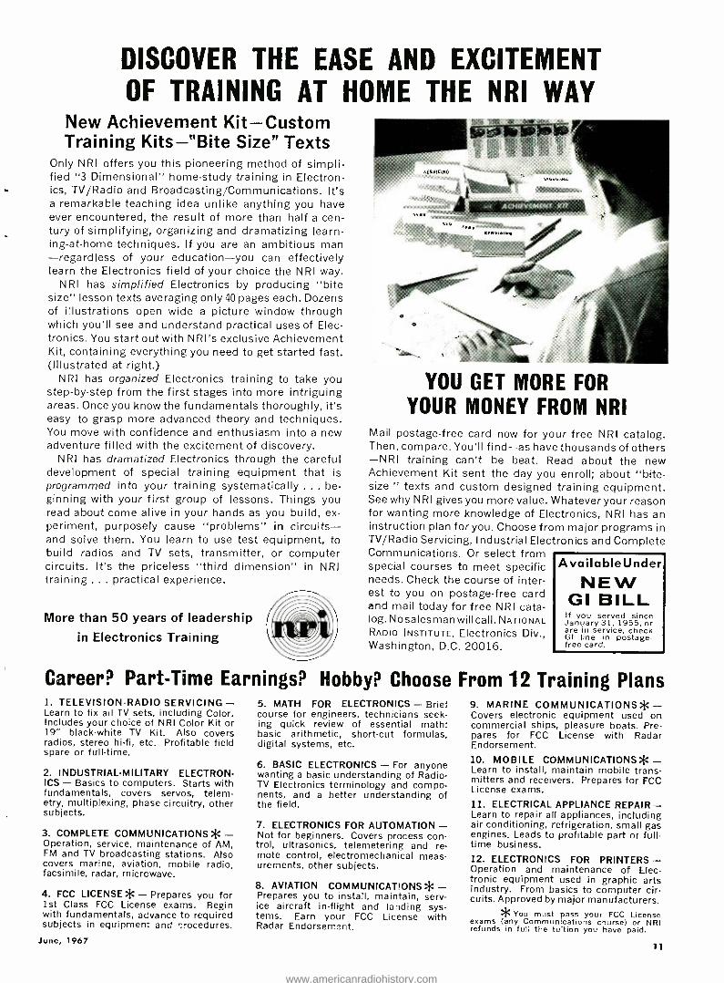
NRI has simplified Electronics by producing "bite size" lesson texts averaging only40 pages each. Dozens of illustrations open wide a picture window through which you'll see and understand practical uses of Elec- tronics. You start out with NRI's exclusive Achievement Kit, containing everything you need to get started fast. (Illustrated at right.)
NRI has organized Electronics training to take you step -by -step from the first stages into more intriguing areas. Once you know the fundamentals thoroughly, it's easy to grasp more advanced theory and techniques. You move with confidence and enthusiasm into a new adventure filled with the excitement of discovery.
NRI has dramatized Electronics through the careful development of special training equipment that is programmed into your training systematically ... be- ginning with your first group of lessons. Things you read about come alive in your hands as you build, ex- periment, purposely cause "problems" in circuits - and solve them. You learn to use test equipment, to build radios and TV sets, transmitter, or computer circuits. It's the priceless "third dimension" in NRI training ... practical experience.
More than 50 years of leadership
in Electronics Training
YOU GET MORE FOR
YOUR MONEY FROM NRI Mail postage -free card now for your free NRI catalog. Then, compare. You'll find -as have thousands of others -NRI training can't be beat. Read about the new Achievement Kit sent the day you enroll; about "bite - size " texts and custom designed training equipment. See why NRI gives you more value. Whatever your reason for wanting more knowledge of Electronics, NRI has an instruction plan for you. Choose from major programs in TV /Radio Servicing, Industrial Electronics and Complete Communications. Or select from special courses to meet specific needs. Check the course of inter- est to you on postage -free card and mail today for free NRI cata- log. Nosalesmanwillcall. NATIONAL RADIO INSTITUTE, Electronics Div., Washington, D.C. 20016.
Available Under
NEW GI BILL If you served since January 31, 1955, or are in service, check GI line in postage - free card.
Career? Part -Time Earnings? Hobby? Choose From 12 Training Plans 1. TELEVISION -RADIO SERVICING - Learn to fix all TV sets, including Color. Includes your choice of NRI Color Kit or 19" black -white TV Kit. Also covers radios, stereo hi -fi, etc. Profitable field spare or full -time.
2. INDUSTRIAL -MILITARY ELECTRON- ICS - Basics to computers. Starts with fundamentals, covers servos, telem- etry, multiplexing, phase circuitry, other subjects.
3. COMPLETE COMMUNICATIONS* - Operation, service, maintenance of AM, FM and TV broadcasting stations. Also covers marine, aviation, mobile radio, facsimile, radar, microwave.
4. FCC LICENSE * - Prepares you for 1st Class FCC License exams. Begin with fundamentals, advance to required subjects in equipment and ' rocedures.
June, 1967
5. MATH FOR ELECTRONICS - Brief course for engineers, technicians seek- ing quick review of essential math: basic arithmetic, short-cut formulas, digital systems, etc.
6. BASIC ELECTRONICS - For anyone wanting a basic understanding of Radio - TV Electronics terminology and compo- nents, and a better understanding of the field.
7. ELECTRONICS FOR AUTOMATION - Not for beginners. Covers process con- trol, ultrasonics, telemetering and re- mote control, electromechanical meas- urements, other subjects.
8. AVIATION COMMUNICATIONS* - Prepares you to install, maintain, serv- ice aircraft in- flight and landing sys- tems. Earn your FCC License with Radar Endorsement.
9. MARINE COMMUNICATIONS* - Covers electronic equipment used on commercial ships, pleasure boats. Pre- pares for FCC License with Radar Endorsement.
10. MOBILE COMMUNICATIONS* - Learn to install, maintain mobile trans- mitters and receivers. Prepares for FCC License exams.
11. ELECTRICAL APPLIANCE REPAIR - Learn to repair all appliances, including air conditioning, refrigeration, small gas engines. Leads to profitable part or full - time business. 12. ELECTRONICS FOR PRINTERS - Operation and maintenance of Elec- tronic equipment used in graphic arts industry. From basics to computer cir- cuits. Approved by major manufacturers. * You must pass your FCC License exams (any Communications course) or NRI refunds in full the tuition you have paid.
11
www.americanradiohistory.com

SC TTSot,
SCOTT'S NEW ONE- AFTERNOON
TUNER KIT DELIVERS
AMAZING FET PERFORMANCE
Now you can get factory -wired per- formance from a kit that takes only one afternoon to build! Scott's new LT -112B is the only kit with Field Effect Transistor circuitry'*, enabling you to enjoy more stations more clearly. Interstation Muting Control effects complete quiet between FM stations ... oscilloscope output al- lows laboratory -precise correction for multipath distortion.
"Scott's LT -112 ... is one of the finest FM stereo tuners we have tested and it is easily the best kit -built tuner we have checked ... Because of its simple con- struction and trouble -free nature, it is a
logical choice for anyone who wants the finest in FM reception at a most remark- able price." HiFi /Stereo Review. LT -112! specifications: Usable sensitivity, 1.8 11V; Cross modulation, 90 dB; Stereo separation, 40 dB; Capture ratio, 2.5 dB; Price, $189.95. WWI aaaeiy
For complete information on the Scott LT -112B, tend for your free copy of Scott's 16 -page fullcolor Illustrated Guide to Custom Stereo.
FREE! 1967 SCOTT
GUIDE TO CUSTOM STEREO Here are 16 colorful, information -packed pages on Scott stereo components .. .
receivers, tuners, amplifiers, speakers ... for 1967. Fact -filled, fully -illustrated articles show you what to look for when buying solid -state components, how stereo works, how to create your own home music system.
NAME
ADDRESS
CITY
STATE Zie
Scott ... where Innovation is a tradition
SCOTTI` H. H. Scott, Inc.,
111 Powdermill Road, Maynard, Mass. Export: H. H. Scott, Inc., Maynard, Mass.
rrices slightly higher west of Rockies. Subject to change without notice
CIRCLE NO. 98 ON READER SERVICE CARD 12
LETTERS FROM OUR
READERS
ELECTRONIC PERCUSSION UNIT To the Editors:
1 have just built the electronic- per- cussion circuit On p. 36 of your Feb- ruary issue. The instrument works per- fectly and I ant very pleased with it. How can 1 change some of the com- ponents to produce the sounds of other percussion instruments, as mentioned in the article?
WILLIAM R. MURPHY Boston, mass.
According to our author, changing the emitter pot in the bongo circuit to a low-resistance unit and critical]!/ ad- justing it just before oscillation results in a bell sound. Other sounds can be produced by experimenting with some of the parts values along the lines indi- cated in the parts list of Fig. 2.
Producing ca cymbal sound is more complex. It requires a noise generator along with a time-delay circuit under push-button control.- Editors
PULSE -COUNTING FM DETECTOR
To the Editors: I read with interest Mr. A. H. Seid-
man's article in the January issue of ELEcTnoNzcs WonLD entitled "Pulse - Counting Detector for FM Tuners."
As you are aware, pulse- counting de- modulators have been in use for several years in command and telemetry re- ceivers designed for military and space applications. The extremely linear volt- age cs frequency characteristic of this circuit renders it particularly well - suited to commercial FM as well.
I\1r. Seidman references in this ar- ticle a paper entitled "Theory of Stronger -Signal Capture in FM Recep- tion" authored by the President and Technical Director of our company, Dr. Elie J. Baghdady. ADCOM, Inc. has been involved in characterization and measurement of FNI- receiver cap- ture performance for some time. Your readers may be interested in some of this company's other contributions in this particular area in addition to the Paper cited in Mr. Seidman's article:
1. Baghdady, E.J.: Lectures on Communication System Theo-
ry, McGraw -Hill Book Co., New York, 1961, pp. 490 -508.
2. "Propagation Characteristics of
the Space Channel," International Telemetering Confer-
ence Proceedings, Vol. 1, Washington, D.C., May 1965.
3. "Signal Cancellation Techniques
for Capturing the Weaker of Two Co- Channel FM Signals,"
presented at the International Conference on Electromag
netic Wave Propagation, liege, Belgium, October 6 -11,
1958. Published in Electromagnetic Wave Propagation,
M. Desirant and 11. Michiels, eds., Academic Press, Lon-
don and New York, 1960, pp. 183 -207.
4. "FM Interference and Noise Sup-
pression Properties of the Oscillating Limiter," 1959 IRE
National Convention Record, Pt. 8, pp. 13 -39. Also IRE
Transactions on Vehicular Communications, Vol. PGVC -13,
September 1959, pp. 37 -63.
5. "New Developments in FM Reception
and Their Application to the Realization of a System of
'Power- Division' Multiplexing," IRE Transactions on Com-
munications Systems, Vol. CS -7, September 1959, pp. 147-
161.
6. "Theory of Feedback Around the
Limiter," 1957 IRE National Convention Record, Pt. 8,
pp. 176 -202.
7. "Interference Rejection in FM
Receivers," MIT Research Laboratory of Electronics Tech-
nical Report 252, September 24, 1956.
8. "Frequency- Modulation Interfer-
ence Rejection with Narrow -Band Limiters," IRE Proceed-
ings, Vol. 43, January 1955, pp. 51 -61.
D. BRADLEY CROW, Sr. Engr. ADCOM, Inc. Huntsville, Ala.
- * 91
PERMANENT MAGNETS FOR METERS
To the Editors: Your reply to Thomas F. McDon-
nell's question, "Will my V.O.M. lose its sensitivity clue to loss of magnetism after being around for, say, 10 or 15
years ? ", which was based on informa- tion given by Portus M. Wheeler, Pres- ident of Crucible Magnet Division of Crucible Steel Co. (p. 6, February, 1967 issue), is only partially true.
I agree that a permanent magnet should not lose more than 1% or 2% of its magnetism over 100,000 years if it is kept under ideal conditions. Howev- er, the permanent magnets used in v.o.m.'s will not always be maintained under ideal conditions. For instance, if the v.o.m. is placed in a tube caddy, carried to and from jobs, carried in and out during cold weather, and is other- wise subjected to vibration, tempera- ture changes, and possible external magnetic fields, the magnet may lose strength. Witness the fact that any me- ter -repair shop working with v.o.m.'s has and uses a magnet charger.
My own experience in working with meters for the past fifteen years has
been that laboratory meters do main- tain their accuracy over extended pe-
(Continued on page 90)
ELECTRONICS WORLD
www.americanradiohistory.com
Not just a slide rule, but the dawn of "a whole new era of quick calculations" for men in electronics An expert reports on the CIE electronics slide rule
June, 1967
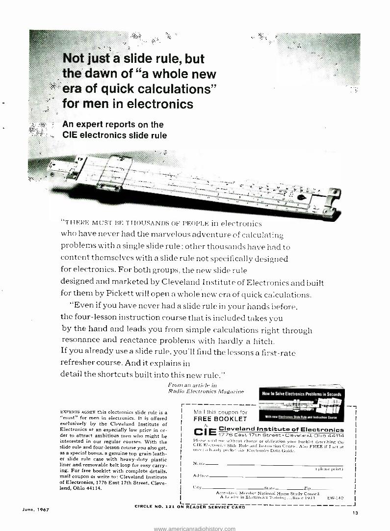
"THERE MUST BE THOUSANDS OF PEOPLE in electronics who have never had the marvelous adventure of calculating problems with a single slide rule : other thousands have had to content themselves with a slide rule not specifically designed for electronics. For both groups, the new slide rule designed and marketed by Cleveland Institute of Electronics and built for them by Pickett will open a whole new era of quick ca:culations.
"Even if you have never had a slide rule in your hands before, the four- lesson instruction course that is included takes you by the hand and leads you from simple calculations right through resonance and reactance problems with hardly a hitch. If you already use a slide rule, you'll find the lessons a first -rate refresher course. And it explains in detail the shortcuts built into this new rule."
From an article in Radio Electronics Magazine
EXPERTS AGREE this electronics slide rule is a "must" for men in electronics. It is offered exclusively by the Cleveland Institute of Electronics at an especially low price in or- der to attract ambitious men who might be interested in our regular courses. With the slide rule and four - lesson course you also get, as a special bonus, a genuine top -grain leath- er slide rule case with heavy -duty plastic liner and removable belt loop for easy carry- ing. For free booklet with complete details. mail coupon or write to: Cleveland Institute of Electronics, 1776 East 17th Street, Cleve- land, Ohio 44114.
r
L
Mail this coupon for FREE BOOKLET
How to Solve Electronics Problems in Seconds
With new Electronics slide Rule and Instruction Course
CE Cleveland Institute of Electronics I ` 1776 East 17th Street Cleveland. Ohio 44114
send me without charge or obligation your booklet describing the CIE Electronics Slide Rule and Instruction Course. Also FREE if I act at once: a handy pocket -size Electronics Data Guide.
Nutt ( please print )
Address
City St+te Zip Accredited Member National Home Study Council
A Leader in Electronics Training... Since 1934 EW -140
CIRCLE NO. 121 ON READER SERVICE CARD J
13
www.americanradiohistory.com

L
EW
LAB TESTED
HI -FI PRODUCT REPORT TESTEI) BY HIRSCH -HOUCK LABS
Dynaco Stereo 120 Power Amplifier Jensen X -40 and X -45 Speaker Systems
Dynaco Stereo 120 Power Amplifier For co1I, of manufacturer's brochure, cirdl1 Al). 25 on Reader Service Card.
THE outstanding performance and reliability of its vacuum -tube ampli-
fiers over the years has no doubt macle Dynaco reluctant to join the switch to transistors. Since such a transistorized amplifier would, at the very least, have to match the performance and rug- gedness of existing models, Dynaco en- gineers were wary of the pitfalls of solid -state design. Their labor has now borne fruit, in the form of the new Stereo 120 power amplifier -and it was well worth the wait.
The Stereo 120 is a dual 60 -watt amplifier, with all silicon transistors. It lias no controls or adjustments, either internal or external, except for the pow- er switch. Although it is equivalent in performance to a pair of the company's " NIark III" amplifiers, it measures a compact 13" x 10í/z" x 4" and weighs
i O.
o O.
50 100 200 500 Ik 2k FREQUENCY -Hz
only 20 pounds. The input impedance is 100,000 ohms, somewhat lower than tube amplifiers. Current models of the manufacturer's PAS -2X, PAS -3X, and PAT -4 preamplifiers will drive it with- out modification. Older versions of Dynaco preamplifiers require a simple change in their output circuits to drive the Stereo 120.
The Stereo 120 is rated with 8 -ohm loads. It will work satisfactorily with 4 -ohm or 16 -ohm speakers, with a pos- sible loss of maximum power capabili- ty at some frequencies.
The amplifier is constructed, for the most part, on three printed -circuit hoards -one for each channel, and one for the power supply. Each amplifier consists of a direct -coupled two- transis- tor amplifier, with d.c. feedback to stabilize the transistor operating points,
DYNACO 120
BOTH CHANNELS DRIVEN 8R LOADS, 120V.A.C. LINE ONE CHANNEL MEASUREDI
REF. -POWER OUTPUT (60W) - - -- HALF -POWER OUTPUT I -3dB1 --- LOW -POWER OUTPUT (-10dB)
A RESIDUAL TEST -EOU P DIST. 0.06 %0
14
5k 1
2.0
IO
zo 0.5
ó
and a four -transistor driver and class -B
power amplifier section. This, too, has d.c. feedback, and there are both a.c. and d.c. feedback paths around the complete amplifier. By virtue of care- ful design, the amplifier is stable under any conditions of drive or load.
The amplifier features a patented protection circuit which limits the peak current drawn by the output transistors to a pre -determined maximum value. The limiting action occurs abruptly, together with a reduction in drive to the output stage. The protective cir- cuit operates when the amplifier is
called upon to deliver excessive power into a too -low load impedance, such as a short- circuited speaker line. Re- moving the short instantly restores nor- mal operation.
The heavily regulated power supply insures the availability of full power for any line voltage from 110 to 130 volts. This is in sharp contrast to ampli- fiers with unregulated supplies, which often lose much of their power capa- bility when operated with low line volt- age. The regulated supply also results in an amplifier whose output is es- sentially the saine whether rated in terns of continuous power ( as rated) or with a music -power rating used by many manufacturers. The power sup- ply is protected against shorts or over- loads by a circuit similar to that used in the output stages. It may be oper- ated short -circuited indefinitely with- out damage.
In our laboratory tests, the Stereo 120 lived up to its promise. Except at 20 Hz, where the distortion was 1% at 60 watts per channel (with in -phase signals si- multaneously drivi) g both char
0.2
0.1 2 5 2 5 IO 20 50
DYNACO 120
BOTH CHANNELS DRIVEN 8R LOADS, 120V.A.C.L NE (ONE CHANNEL MEASURED)
--IkHZ TOTAL HARM D ST.
- - -- 60/7000 Hz (4.I1 IM DIST.
_)
/
r
CONTINUOUS(EOUIV.) SINE -WAVE POWER OUTPUT PER CHANNEL -WATTS
ELECTRONICS WORLD
100
www.americanradiohistory.com
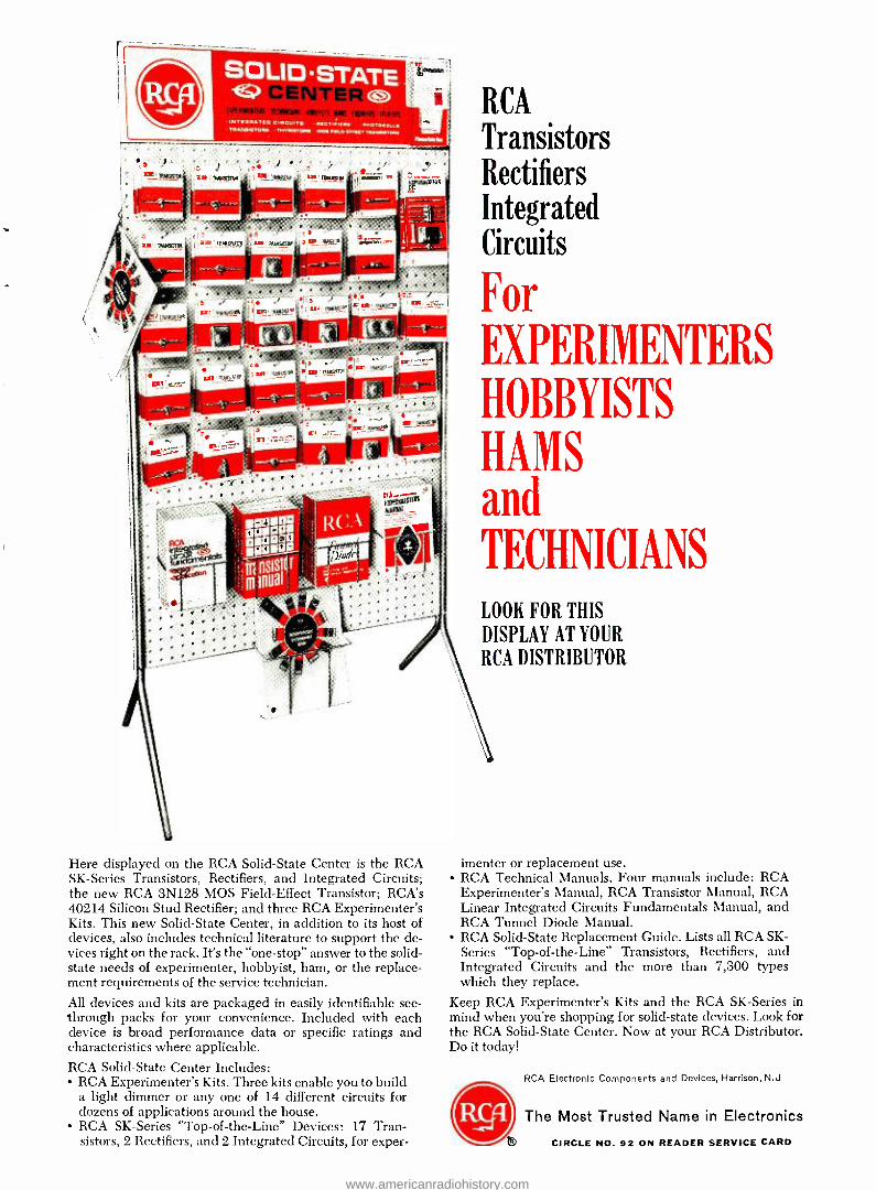
Here displayed on the RCA Solid -State Center is the RCA SK- Series Transistors, Rectifiers, and Integrated Circuits; the new RCA 3N128 MOS Field- Effect Transistor; RCA's 40214 Silicon Stud Rectifier; and three RCA Experimenter's Kits. This new Solid -State Center, in addition to its host of devices, also includes technical literature to support the de- vices right on the rack. It's the "one- stop" answer to the solid - state needs of experimenter, hobbyist, ham, or the replace- ment requirements of the service technician.
All devices and kits are packaged in easily identifiable see - through packs for your convenience. Included with each device is broad performance data or specific ratings and characteristics where applicable. RCA Solid -State Center Includes:
RCA Experimenter's Kits. Three kits enable you to build a light dimmer or any one of 14 different circuits for dozens of applications around the house. RCA SK- Series "Top -of- the -Line" Devices: 17 Tran- sistors, 2 Rectifiers, and 2 Integrated Circuits, for exper-
RCA
Transistors Rectifiers Integrated Circuits
For EXPERIMENTERS
HOBBYISTS
HAMS and TECHNICIANS
LOOK FOR THIS
DISPLAY AT YOUR
RCA DISTRIBUTOR
imenter or replacement use. RCA Technical Manuals. Four manuals include: RCA Experimenter's Manual, RCA Transistor Manual, RCA Linear Integrated Circuits Fundamentals Manual, and RCA Tunnel Diode Manual. RCA Solid -State Replacement Guide. Lists all RCA SK- Series "Top -of- the -Line" Transistors, Rectifiers, and Integrated Circuits and the more than 7,300 types which they replace.
Keep RCA Experimenter's Kits and the RCA SK- Series in mind when you're shopping for solid -state devices. Look for the RCA Solid -State Center. Now at your RCA Distributor. Do it today!
RCA Electronic Components and Devices, Harrison, N.J
The Most Trusted Name in Electronics
CIRCLE NO. 92 ON READER SERVICE CARD
www.americanradiohistory.com

Complete your stereo system with the
Sony solid -state 350!
The brilliantly professional Sony solid -state 350 stereo tape deck recorder is the ideal way to add the superior performance of tape to your component system. With an instant connection to your stereo system, the versatile two -speed 350 places at your pleasure a full array of professional fea- tures. Three heads for tape -and- source monitoring. Vertical or horizontal oper- ation. World -famous Sony stereo recording amplifiers and playback pre - amps. Dual VU meters. Auto shut -off. And a set of specs designed to put your speakers to the test of excellence. Fre- quency response: 50- 15,000 cps. S.N. ratio: minus 50db. Flutter and wow: under 0.15 %. The 350's black and gold decor is complemented by a hand- somely luxurious walnut -grain base. It's all yours to enjoy for under $199.50. Should you want to add portability to your 350, there's the 350C, mounted in a dark gray and satin -chrome carrying case, at less than $219.50. For further information, write Superscope, Inc., Sun Valley, California, Dept. S- 25
SONY'S PROOF OF QUALITY A FULL ONE YEAR WARRANTY
SONY AMERICA'S FIR` CIRCLE NO. SN
16
SUPERSCOPE ®
-'N TAPE RECORDERS cERVICE CARD
the measured distortion was under 0.2% at any power level up to 60 watts, and at any frequency from 30 to 20,000 Hz. Over most of the frequency range it was immeasurable, even at full power, since the residual harmonic distortion of our test instruments is about 0.06`, and our measured figures On the amplifier were typically 0.07 to 0.08 %.
At 1000 Hz, the distortion was immea- surable up to about 70 watts, where it reached 0.1 %. The Iii distortion was un- der 0.2% up to 60 watts. It is obvious that in order to measure the distortion of this amplifier with any validity, one must go beyond ordinal.}. commercial laboratory instruments, few of which can be trusted below 0.1%.
Driving the amplifier to the point where the output clipped, we measured 66 watts per channel into 8 ohms, 90 watts into 4 ohms, and 37.5 watts into 16 ohms. The 90 -watt power into 4 ohms represents, in practice, a sort of - music-
power" rating, since the amplifier will not sustain that power for any significant tine. It does offer a welcome, and most useful, power for driving low- efficiency 4 -ohm speakers.
Dtlnaco, quite logically, claims that the Stereo 120 should be indistinguish- able sonically from a pair of "Mark III's ". This is no small achievement in itself. We did not make the compari- son, but can testify that the Stereo 120 sounded like the powerful, virtually dis- tortionless amplifier that it is. It had the clarity and effortless quality at all levels that we have come to expect from a very powerful, clean amplifier. Its small size and weight and cool operation should make it especially suit- able for installation in limited space where vacuum -tube amplifiers would require forced cooling.
The Stereo 120 sells for 5159.95 in kit form or 5199.95 in the factory wired version. A
Jensen X -40 and X -45 Speaker Systems For copy of ma utfacltiter'.s broclutrc, circle No. 26 on Reader Service Card.
BEFORE the advent of compact or "bookshelf" speaker systems, it was
rare to find a speaker of any reasonable size which could deliver an audible 30- liz fundamental output. Sluch of the supposed "bass" response of the big speaker systems that were prominent
w Z o
lo
o
10
15
10 or 15 years ago consisted of distor- tion products.
The acoustic suspension speaker sys- tems, with their highly compliant, long - throw cones in small, fully scaled en- closures, brought true bass to large
(Continued on page 84)
PEAKS CAUSED BY ROOM RESONANCES JENSEN X40 SPEAKER SYSTEM -FREQUENCY RESPONSE- CORRECTED FOR ROOM RESPONSE BELOW 100011,- AVERAGE OF B INDOOR RUNS
20 50 100 200
TONE BURST
)
TONE
¡BURS li 5 TO Ik 2k 51, IOk 20k
FREQUENCY - Hz
CIRCLE NO. 197 ON READER SERVICE CARD-4-
www.americanradiohistory.com
Your Sylvania distributor is up- to -date on your business. Use him: it's like adding an electronic consultant to your staff ...free. We keep him up -to -date with frequent reports and analyses of your maintenance and design needs. We give hin plant tours and technical training. And ready Lccess to Sylvania product and applications enginee °i ng staffs. He kncws the features of each and every tube we make. And he knows how you use them. He's up on the latest developments. He knows our competitors' tubes hside out, too. Get a f :2e analysis, by your Sylvania distributor, of your tube and semiconductor replacement needs. He can prevent emergencies, prepare an inventory - and save you money. He's an expert. Depend on him for service and for fast delivery -in any quantity. Sylvania Electronic Tube Division, Electronic Com- ponents Group, Seneca Falls, New York 13148.
SYLVAN l 1 SUBSIDIAR' JF
GENEFALTELEPHONE & ELECTRONICS GTE
www.americanradiohistory.com

TAKE
THE FIRST
BIG STEP.
TOWARD
A REWARDING.
CAREER IN
ELECTRONICS Mail card to RCA Institutes today
Thousands of well paid jobs for Electronics Technicians are
unfilled now
RCA Institutes Can Train You - At Home -And Help You Qualify
For This Work
It's a sad, but true, fact that today, with so many men yearning for better jobs and better incomes, thousands of well paid jobs are un- filled in the vast electronics industry.
Many of the men who could fill these jobs - that is, men with the aptitude and native inter- est to enjoy a career in electronics -are handi- capped because for one reason or another they have not had the opportunity to train themselves for these lucrative positions.
18 ELECTRONICS WORLD
www.americanradiohistory.com

NOW- THANKS TO RCA
INSTITUTES
HOME STUDY-
` YOU CAN TRAIN
FOR A CAREER
IN ELECTRONICS
Realizing that thousands of technical jobs -well paid jobs -in electronics are going unfilled each week, RCA
Institutes has done something posi- tive about the problem. To benefit the electronics industry, with its cry- ing need for trained men ... and to
help men who really want to move into a well paid electronics job, RCA
Institutes offers an ideal home train- ing program!
HOME STUDY CAN PROVIDE CAREER OPPORTUNITIES!
To help meet the need for qualified men in the electronics field, RCA Institutes has created a wide variety of Home Training Courses, all aimed toward a profitable, exciting elec- tronics career in the shortest pos- sible time. Included are exclusive "Career Programs" designed to train you quickly for the job you want! Your study program is supervised by
RCA Institutes experts who work with you, help guide you over any "rough spots" that may develop along the way.
OFF TO A FLYING START WITH AMAZING RCA "AUTOTEXT" METHOD
Each "Career Program" starts with the amazing "AUTOTEXT" Pro- grammed Instruction Method - the new, faster way that's almost auto- matic! "AUTOTEXT" helps even those who have had trouble with conventional learning methods in the
June, 1967
past. It is truly the "Space Age" way to learn everything you need to know with the least amount of time and effort.
RCA INSTITUTES ENGINEERED
KITS SPEED YOUR PROGRESS
To speed you on your way to a suc-
cessful electronics career, your "Career Program" will include a
variety of RCA Institutes engineered kits at no extra cost -each complete in itself. As a bonus, you will also receive and build a valuable Oscillo- scope. You'll get the new Pro- grammed Electronics Breadboard for limitless experiments, including building a working signal generator and a fully transistorized superheter- odyne AM receiver and Multimeter.
CHOOSE YOUR CAREER PROGRAM NOW
To get a head start today on the elec- tronics career of your choice, look over this list of RCA Institutes "Career Programs ", pick the one that appeals most to you, and check it off on the attached card:
Television Servicing Telecommunications FCC License Preparation Automation Electronics Automatic Controls Digital Techniques Industrial Electronics Nuclear Instrumentation Solid State Electronics Electronics Drafting
To meet other specific needs, RCA
Institutes also offers a wide variety of separate courses which may be
taken separately from the "Career Programs ". These range from Elec- tronics Fundamentals to Computer Programming. They are described in
the material you receive.
ADVANCED TRAINING TOO
If you are already working in elec- tronics or have some experience but want to move on up, you may start RCA Institutes training at an ad- vanced level. No tedious repetition of work you already know!
UNIQUE TUITION PLAN
With RCA Institutes, you learn at
your own pace, and you pay only as
you learn. There are no long term contracts to sign ... no staggering down -payments to lose if you decide to stop...no badgering bills. You pay for lessons only as you order them,
and should you decide to interrupt your training at any point, you may do so and not owe one cent.
CLASSROOM TRAINING AVAILABLE
RCA Institutes Resident School is
one of the largest schools of its kind in New York City with classroom and
laboratory training available in day or evening sessions. Coeducational classes start four times a year. Just check "Classroom Training" on the attached card for more details.
FREE PLACEMENT SERVICE, TOO!
In recent years, 9 out of 10 Resident School students who used the Free Placement Service have been placed before or shortly after graduation. This Service is now available to Home Study students.
ALL RCA INSTITUTES COURSES AVAILABLE UNDER NEW GI BILL.
SEND ATTACHED POSTAGE PAID CARD TODAY FOR COMPLETE INFORMATION. NO OBLIGATION. NO SALESMAN WILL CALL.
RCA INSTITUTES Inc. Dept. EW -67
A Service of Radio Corporation of America
350 West 4th Street, New York, N. Y. 10014
The Most Trusted Name in Electronics
21
www.americanradiohistory.com

MALLORY Tips for Technicians Ar When you need a stable capacitor...
.........
-
5/
IOW1 MALLORY P OLYSTYRENE
4 -25 0 25 50 75 100
Degrees Centigrade Capacitance vs. Temperature
{-2
C o
0. G
n
+ 1 p0< yFS
MALLORY TFR I` POLYSTYRENE .05%
0 -25 0 25 50 75 10 Degrees Centigrade
Dissipation Factor vs. Temperatur
1,000,000 500,000
100,000
É 50,000 L
d 10,000
? 5,000
1,000 -25 0 25 50 75 10 Degrees Centigrade
Insulation Resistance vs. Temperature CIRCLE
22
Temperature makes most capacitors wander. For electrolytics, capacitance goes down when temperature gets colder, goes up when things get hot. But this usually doesn't cause trouble, because most electrolytic applications are in filtering -and as long as you have low enough AC impedance, you get the filtering you need. Where drift can bring problems is in tuned circuits, timing and differentiator circuits; here you've got a paper, film, ceramic or mica capacitor, in the fractional - microfarad range. If it changes value due to temperature varia- tions or just plain old age, you're going to have some headaches.
Today's tip: when you need extra stability, try the new Mallory polystyrene capacitors. They're the most stable you've ever seen. They look different, and they act different. They're made of a unique kind of stretched polystyrene film and high purity aluminum foil, wound up in a compact roll and then fused together in a self -sealed case of solid clear plastic.
What's extra special about these new capacitors is the way they hold their original microfarad value while temperature varies all over the lot. Temperature coefficient is considerably lower than that of polyester film capacitors -under 150 parts per million per degree C. And it's negative -which means that instead of going up with temperature, capacitance goes down. This is the direction you need to change capacitance in order to compensate for the effect of temperature on the inductive part of a tuned circuit. From -10 °C to +70 °C, their total capacitance change is less than 1.3 %. And brother, that's stable!
And that's not all. These little dandies don't grow old. They hold their characteristics month after month. You just connect 'em and forget 'em.
One more thing. Mallory Polystyrene Capacitors have the lowest dielectric loss in the business. Their dissipation factor (similar to power factor, a measure of efficiency as a capacitor) is extremely low ... only 0.05%, which is a small fraction of that of other capacitors. And it stays at this low value over the whole temperature range. This means that they're high Q capacitors, ideal for tuned circuits. And their insulation resis- tance is way higher than polyester, mica or paper capacitors.
In case you were wondering how much dough you would have to lay out to get such wonderful capacitors- here's the best news of all. They are really low priced. You can get them in values from 5 pF to .01 mfd, all rated 600 volts, from your Mallory Distributor. See him soon -and ask for your copy of the 1967 Mallory General Catalog. Mallory Distributor Products Company, a division of P. R. Mallory & Co. Inc., Indianapolis, Indiana 46206.
NO. 104 ON READER SERVICE CARD t.'.éCÏRONICS WORLD
www.americanradiohistory.com

A fluidic time -based sequencer used to control a glass press is shown here. This digital control system, the most compli- cated fluidic system ever assembled, con- tains 1050 standard active and passive de- vices in a relay rack two feet square by six feet high. It will replace an electro- mechanical press control that requires man- ual adjustment of valve -actuating cams taking more than an hour for setup. Flu- idic control setup time is under 15 min.
FLUIDIC SYSTEMS By C. J. MILLER /Fluidic Products Dept., Corning Glass Works
.-lir flowing through plastic. tubing ran be made to perform prany of the very sane functions as electrons flowing in conductors. -llthough far slower than electronic components. fluidic systems
are much simpler and more reliable in a good many applications.
FLUIDIC systems, the newest and most promising type of control, may at first glatsce seem to be the province of mechanical rather than electronics engineers. This is
because the operating principles of fluidic devices involve aerodynamics and fluid mecharics. Put, since fluidic de- vices can sense, count, amplify, and control, it is natural for
the technology to be of interest to those in the electronics fields concerned with control systems.
The terminology is the same as in electronics, i.e., there ate fluid amplifiers, nor gates, and gates, resistors, flip -flops, binary counters, and Schmitt triggers. Although fluidic de- vices operate on somewhat different principles, the fune-
June, 1967 23
www.americanradiohistory.com
tions performed are the same as those handled by their electronic counterparts. As a matter of fact, about 90 per- cent of all fluidic applications are in areas where electronic components or systems perform similar functions.
Fluidics involves the passage of a fluid -usually air - through mechanical components having carefully made channels and passages. These components are usually inter- connected with plastic tubing. The fluid (air) in the system is maintained at some constant low pressure by means of some type of compressor. Fluidics will never replace elec- tronics entirely, but can, however, function in environments and in certain applications where electronics is incapable of performing well. Let us take a look at some of the advan- tages and limitations of fluidic devices.
Advantages & Limitations Pure fluidic devices have no moving parts. Longer com-
ponent life can be expected since there is minimal wear which provides a decided advantage over electro- mechanical parts.
Nuclear radiation has no effect on fluidic devices and such units can operate in an atmosphere where electronic components would have limited life. Fluidic instruments used to detect thickness, erosion, and liquid level with gamma and beta radiation sources are now employed in both commercial and military applications.
Since fluidic devices are explosion- proof, control panels may be located in the explosive area rather than in some remote place. Since such devices are operated by fluids - usually air -there is no need to house them in explosion - proof enclosures.
Other advantages include the fact that fluidic devices are free from vibration and have been known to perform up to 15,000 G's with negligible change in output. Environ- mental heat can be readily handled by most fluidic devices
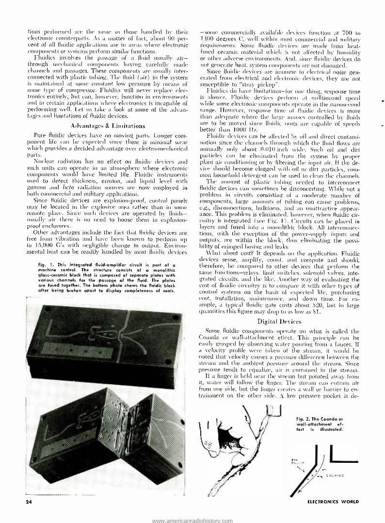
Fig. 1. This integrated fluid -amplifier circuit is part of a machine control. The structure consists of a monolithic glass- ceramic block that is composed of separate plates with various channels for the passage of the fluid. The plates are fused together. The bottom photo shows the fluidic block after being broken apart to display completeness of seals.
24
-some commercially available devices function at 700 to 1400 degrees C, well within most commercial and military requirements. Some fluidic devices are made from heat - fused ceramic material which is not affected by humidity or other adverse environments. And, since fluidic devices do not generate heat, system components are not damaged.
Since fluidic devices are immune to electrical noise gen- erated from electrical and electronic devices, they are not susceptible to "stray pickup ".
Fluidics do have limitations -for one thing, response time is slower. Fluidic devices perform at millisecond speed while some electronic components operate in the nanosecond range. However, response time of fluidic devices is more than adequate where the large masses controlled by fluids are to be moved since fluidic units are capable of speeds better than 1000 Hz.
Fluidic devices can be affected by oil and direct contami- nation since the channels through which the fluid flows are normally only about 0.010 -inch wide. Such oil and dirt particles can be eliminated from the system by proper plant air conditioning or by filtering the input air. If the de- vice should become clogged with oil or dirt particles, com- mon household detergent can be used to clean the channels.
The amount of plastic tubing needed to interconnect fluidic devices can sometimes be disconcerting. While not a problem in circuits consisting of a moderate number of components, large amounts of tubing can cause problems, e.g., disconnections, bulkiness, and an unattractive appear- ance. This problem is eliminated, however, when fluidic cir- cuitry is integrated ( see Fig. 1) . Circuits can be placed in layers and fused into a monolithic block. All interconnec- tions, with the exception of the power -supply inputs and outputs, are within the block, thus eliminating the possi- bility of crimped hosing and leaks.
What about cost? It depends on the application. Fluidic devices sense, amplify, count, and compute and should, therefore, be compared to other devices that perform the same functions -relays, limit switches, solenoid valves, inte- grated circuits, and the like. Another way of evaluating the cost of fluidic circuitry is to compare it with other types of control systems on the basis of expected life, purchasing cost, installation, maintenance, and down time. For ex- ample, a typical fluidic gate costs about $20, but in large quantities this figure may drop to as low as $1.
Digital Devices Some fluidic components operate on what is called the
Coanda or wall- attachment effect. This principle can be easily grasped by observing water pouring from a faucet. If a velocity profile were taken of the stream, it would be noted that velocity causes a pressure difference between the stream and the ambient pressure around the stream. Since pressure tends to equalize, air is entrained in the stream.
If a finger is held near the stream but pointed away from it, water will follow the finger. The stream can entrain air from one side, but the finger creates a wall or barrier to en- trainment on the other side. A low pressure pocket is de-
Fig. 2. The Coanda or wall- attachment ef- fect is illustrated.
ELECTRONICS WORLD
www.americanradiohistory.com

Oj SUPPLY CHANNEL (PORT)
O POWER NOZZLE (JET)
CONTROL CHANNEL (PORT) A
O CONTROL CHANNEL PORT) R
OWALL ATTACHMENT AREA
O SPLITTER
Oj OUTPUT CHANNEL (PORT /LEG) F1
O OUTPUT CHANNEL (PORT /LEG) F2
O VENT
Fig. 3. The design of the channels or passages through which the fluid is made to flow in a fluidic flip -flop component.
veloped against the finger and the higher ambient pressure on the other side of the stream will hold it against the finger, or similarly, the wall of a fluidic device. See Fig. 2.
The first fluidic devices were designed on this basic prin- ciple. Fig. 3 shows a flip -flop or bistable device in which the fluid (usually air) enters through the power nozzle and attaches itself to one of the walls and then exits through one of the output legs. For example, if the stream attaches itself to output leg F1, it will continue on that side as long as the power nozzle is operating or until a control signal which is large enough to detach the fluid from the wall is introduced at control port A. The stream will then attach itself to the opposite wall and exit through output leg F2. It will con- tinue in this direction even if the control signal is removed. The device is instable, that is, it is stable with output from either of the two output legs.
A monostable fluidic device is designed to exit the air stream out one leg unless a control signal is introduced to switch its output ( Fig. 4) . The stream, however, will re- turn to its biased or preferred output leg if the control signal is off. The device can be compared to a spring -return valve without a spring.
This device is an or/nor gate. If a control signal is intro- duced through either one of the two control ports, the stream will exit by the or output leg. The stream switches to the 7101' output leg when both of the control inputs are off.
A one -shot multivibrator creates an output pulse for a fixed period of time no matter what the duration of the in- put signal ( Fig. 5). It is a nor gate arranged so that the in- put signal is split in two, one stream going direct to the con- trol input, the other to a delay line and then to the auxiliary control port. \ \Then the control signal is applied, input is switched from the nor output leg to the or leg. The same control signal then reaches the auxiliary control port and balances the pressure signal through the control port. Since the two pressures are now equal, the device sees zero con- trol pressure and switches back to the nor leg. The fixed duration of the pulse out of the or leg is determined by the length of the delay line used.
In addition to these basic devices, single and multi -stage binary counters, and gates, half and full adders, shift reg- isters, majority gates, Schmitt triggers, binary -to- decimal converters, and other such fluidic (Continued on page 78)
Auxiliary Control Port
Wall
Supply Port
Power Jet
Spldlef
t Vent Ventt
Control Ports
Or Output Leg 'Nor °Output Leg
Fig. 4. Design of the channels in monostable "or /nor" gate.
DELAY
AUXILIARY INPUT
u u
OSIGNAL INPUT
OR NOR
CONTROL INPUT
Fig. 5. The fluidic circuit arrange- ment of a one -shot multivibrator.
Fig. 6. The fluid channels in a proportional- design component
Control Port1
Vent
Output Port 1 Output Port 2
Control Port 2
Vent
June, 1967 25
www.americanradiohistory.com

MEASURING TRACKING ABILITY
OF PHONO CARTRIDGES
By J. H. KOGEN /Chief Engineer, Shure Brothers, Inc.
To avoid distortion when tracking records with high peak modulation levels, the stylus tip mast not lost contact with the record groove. //ere are a number of present and proposed methods of measuring this important cartridge parameter, including a new rariable -speed turntable method, CCIF technique, and the use of tone bursts. scope observations, and special test records.
ONE of the most difficult problems encountered by a phonograph cartridge is that of maintaining proper contact between the stylus tip and the record. The
need for maintaining this contact is obviously one of the fundamental requisites for proper performance of the pho- nograph system. Solving this problem has become more and more difficult in recent years because of the improvements in record -cutting techniques, in amplifiers and speakers, and the increased expectations of the sophisticated listener.
A number of terms have been used to describe the ability of a phono cartridge to maintain proper contact between stylus tip and record. These include: trackability, imped- ance, adhnittance, and a host of flowery adjectives which re- late primarily to subjective evaluation. In this article, we will use the term "tracking ability"
The availability of high -quality records with higher and higher peak modulation levels has created the need for bet- ter tracking ability. Records are being made today with peak modulation levels as high as 20 centimeters per second at 15 kHz. Such modulation requires acceleration of about 1800 C's. For example, the Nonesuch record "Four Concer- tos for Harpsichord and Orchestra" has levels of roughly 25 cm /s at 1() kHz. Another example of a highly modulated record is London's "Kismet" which shows levels of 18 cm /s at 11 kHz. Many other records containing high modulation peaks can be cited. This places the onus on the phono car- tridge to reproduce what has been impressed on the grooves.
One very important factor which must be considered in defining phono- cartridge tracking ability is the tracking force used during normal play. Minimum tracking force, consist- ent with good tracking ability, should be used. This is clone to minimize wear on both record and stylus. Tracking ability can be improved, especially at lower frequencies, by in- creasing the tracking force. However, this reduces stylus and record life. When checking the tracking ability of the car- tridge or 'lien comparing cartridges, evaluation should be made on the basis of a specified tracking force and an as- sumption that the lower the tracking force, the long er the life (when proper tracking is assured).
Tracking _Ability vs Frequency A further consideration is that tracking ability varies with
frequency. A phono cartridge is expected to reproduce fre- quencies in the range of 20 to 20,000 Hz. The tracking abil- ity of the stylus is directly related to its mechanical
impedance. This impedance acts like a multi -mesh elec- trical circuit or a complex mechanical circuit and, as such, its impedance varies with frequency. The modulation levels on records also change as a function of frequency, as speci- fied by the RIAA recording characteristic, and because of the spectral content of the program material.
The problem is to provide suitable tracking ability to match the modulation levels at all frequencies within the audio spectrum. This should be considered when making measurements since a reading at one frequency won't per- mit a prediction about operation throughout the spectrum.
What Does Loss of Tracking Do? Loss of tracking occurs when the dynamic force applied
to the stylus tip exceeds the tracking force. \ \'hen this hap- pens, the tip leaves the surface of the record and later comes bouncing back onto the record surface. During the period when the stylus is not touching the record it obviously is not reproducing the material on the record but is producing some uncorrelated signal, probably related to the free -air dynamic characteristics of the stylus. When the stylus re- turns to the record a broad baud of noise is produced. Sub- jectively, this result can be heard even by the untrained listener. The sound of bells becomes dull thuds; the staccato sound of castanets resembles sandpaper being rubbed on a blackboard; while the sound of an "s" in a word like "serv- ice" conies out as an exaggerated hiss.
In terms of measurement, if one were to plot distortion versus modulation level, a curve much like that shown in Fig. 1 would be obtained. Distortion would remain at a rela- tively low level up to the point where the cartridge could no longer track the modulation. At this point, which in Fig. I
would be around 25 cm /s, distortion increases at aver' rapid rate. Distortion products at modulation velocities above 25 cm /s, for this particular example, would definitely be discernible to the listener.
Methods 1T,edl in the Past For many years now, manufacturers have tested the track-
ing ability of their cartridges at low frequencies. The mea- surement was normally made using a record with several bands of constant low -frequency (100 Hz or 400 Hz) modu- lation at varying levels. The output of the phono cartridge was fed to a scope and the sine wave observed. The wave- form was observed while the cartridge played each band at
ELECTRONICS WORLD
www.americanradiohistory.com

40
35
30
25
20
15
10
5
i J B
5 10 15 20 25 30 35 40 45 50 55
PEAK MODULATION LEVEL -cm/s Fig. 1. Intermodulation distortion for various peak modula- tion levels (actually recorded velocities) for phono cartridge tracking at 1 gram. Frequencies are 400 and 4000 Hz on RCA 12 -5 -39 test record. Although level is fairly high at point A, distortion is still acceptably low. At point B distortion begins to rise rapidly ultimately reaching excessively high value at C.
higher modulation velocities until a band was found where the waveform showed breakup. The maximum velocity at which the cartridge would track without breakup was desig- nated as its "tracking ability ".
Such a reading at a single frequency provided what was essentially a low- frequency rating of tracking ability. The test made no evaluation of high- frequency tracking ability, say in the 5 -kHz region and above, and gave a relatively poor indication of performance in the region between 1 kHz and 5 kHz.
A more refined method of measuring tracking ability would involve an evaluation of performance across the entire frequency spectrum rather than only at 100 or 400 Hz. Some of the means for doing this will be described.
Variable -Speed Turntable Method One problem in developing a suitable means of measuring
tracking ability is cutting the test record. The high peak modulation levels which exist on modern, good- quality rec- ords are always found under transient conditions. In order to take a reading, one needs a signal for a reasonable period of time, say at least two seconds and preferably five sec- onds. Present -day cutters can't cut such high modulations at high frequencies for any such extended periods of time.
One solution to this problem is to cut the record at slow speed and play it back at a higher speed. For example, if the record is cut at 1000 Hz with a modulation level of 5 cm /s at 33 r /min and is then played back at twice the speed (66 r /min), the electrical output from the cartridge will be 2000 Hz at a level proportional to 10 cm /s. Using this prin- ciple, Shure cut a record for laboratory use (not available for general sale) with the bands shown in Table 1. This record is used in conjunction with a variable -speed turntable which is continuously adjustable from 25 to 100 r /min. The turn- table is fitted with a vacuum system which holds the record absolutely flat against the turntable surface. A vacuum is created between the under surface of the record and the turntable, and the record held against the turntable by at- mospheric pressure.
At the start the phonograph cartridge is placed in the low- est frequency band while the table is turning at 25 r /min. The sine -wave output of the cartridge is observed on a scope. The turntable speed is then slowly increased until breakup is seen on the CRO screen. The turntable speed is then re- duced to the point where the sine wave returns and the read- ing (in r /min) is recorded. Scope patterns before and after breakup are shown in Fig. 2.
Frequency and modulation velocity for the measured point is then determined from a graph such as the one shown
June, 1967
BAND CHANNEL PEAK VELOCITY (cm /s)
33 r /min 78 r /min
I FREQUENCY (Hz) 33 r /min 78 r /min
1 L 6.8 16.1 5,000 11,800 2 R 6.3 14.9 5,000 11,800 3 L 7.0 16.6 10,000 23,600 4 R 7.0 16.6 10,000 23,600 5 L 4.5 10.7 10,000 23,600 6 R 5.0 11.8 10,000 23,600 7 L 1.8 4.3 10,000 23,600 8 R 1.9 4.5 10,000 23,600 9 L 0.8 1.9 10,000 23,600
10 R 0.8 1.9 10,000 23,600
Table 1. Characteristics of laboratory test record used.
Fig. 2. Upper waveform is from a cartridge that is just barely tracking the sine -wave modulation. Lower waveform shows distortion produced when cartridge is not tracking.
in Fig. 3. Such a graph is provided for each band on the rec- ord and, with r /min known, frequency and peak modulation velocity can be determined.
This procedure is followed for all bands on the record. The record of Table 1 provides measurements above 5 kHz while another record is used for frequencies below 5 kHz. A series of points is thus determined which can be plotted on a curve like that of Fig. 4 which shows the peak modu- lation velocity the cartridge will track at the specified track- ing force. The locus of the points is a curve of the cartridge's tracking ability at the specified tracking force. Fig. 5 plots the tracking ability of a number of cartridges using this method of measurement. It also demonstrates the variation among cartridges in this respect.
CCIF Method
There are two disadvantages to the method just described. First, it requires a variable -speed turntable equipped with a
vacuum attachment. Second, the means of detecting the point of loss of tracking ability is not as well defined as it could be. It may be possible to resolve both of these prob- lems using the CCIF (International Telephonic Consultative Committee) method of determining distortion.
This method involves the use of two frequencies sepa- rated by a constant frequency difference, usually on the order of a few hunched Hz. As these two frequencies are swept across the audible spectrum, the output is measured as the difference frequency. This can be done quite simply by using a filter tuned to the difference frequency and a voltmeter. If no distortion exists, the output at the difference frequency should be zero. When distortion is encountered, inter - modulation will occur and output will be obtained at the dif- ference frequency. A block diagram of a setup for making such a test is shown in Fig. 6. Using a record with several bands (of CCIF frequency sweeps) at increasing modula- tion levels, provides a means for measuring tracking ability.
The measurement is made as follows. Assume the record is cut with a series of bands having frequency sweeps from 1000 to 20,000 Hz, with each band cut at a peak modulation velocity 1 cm /s higher than the previous band. Assume fur-
27
www.americanradiohistory.com

5
3.8
4
3
2
20.4
È
a 68
5.!
25 3 50 D TABLE SPEED -r /min
Fig. 3. Typical calibration chart for one band of special test record. Frequency and velocity vary as turntable speed.
75 Ica
25
20
15
10
5
10
8
6
4
3
2
20 100 k
FREQUENCY -Hz
Fig. 4. Typical tracking -ability curve showing maximum modula- tion velocity the cartridge can track as function of frequency.
10k 20k
---- /-_-= _`= .... \_ ̀ -"-. \. ̀ `
AY1
t
.- ..............
..... ' \\ t
\
\ \ \ \ ..
r -t' >
\, '' 400 600 800 Ik 2k 4k 6k
FREQUENCY -Hr
Fig. 5. Tracking ability of a grouping of current cartridges.
8k 10k 20k
ther that there are 20 bands running from .5 cm /s to 24 cm /s. Measurements are made through a filter which passes only the difference frequency. The recorder speed is syn- chronized with the frequency sweep to provide frequency calibration. The resulting graph plots the difference inter - modulation products as a function of frequency for each of the modulation levels.
At this point some arbitrary statement must be made as to how much distortion constitutes an indication that the cartridge is no longer tracking properly. Referring to Fig. 1, we would have to choose a value of distortion for point B. Let us arbitrarily say that distortion at 13 should have a value
of 10% of the peak output of the cartridge when it is tracking properly at 1 kHz for the modulation level at which the measurement is made. We might then pick points from the graphs recorded in the setup shown in Fig. 6 and replot them in a fashion similar to that shown in Fig. 4. In this case, the ordinate of Fig. 4 could be defined more specifically as the tracking ability, in terms of modulation velocity which the cartridge is able to track properly with less than 10% CCIF distortion.
An alternative might be to have the bands on the record cut with pairs of fixed frequencies, with sub -bands at increas- ing modulation levels. The advantage here would be that one would only have to count up the number of sub -bands to determine the modulation level at which distortion exceeded 10%.
One of the advantages of the CCIF method is that the only special equipment required is a band -pass filter at the difference frequency. In addition, loss of tracking is indicated as a definite percentage of distortion rather than as a judg- ment of the scope pattern as is the case with the variable - speed technique. The CCIF method allows measurement up to the maximum frequency of interest, a thing that is quite difficult to do if the amount of total harmonic distortion were measured.
RCA has recently issued test record No. 12- 5 -10.5v which includes most of the facilities for making a sweep frequency CCIF measurement. This record has several sweep bands from 2 kHz to 20 kHz with a difference frequency of 400 Hz at modulation levels of 3.54 em s, 5.6 cm 's. 8.8.5 cm s, and 14.0 cm /s. The only limitation we have noted in this
INPUT FROM TEST RECOR:
2-FREQUENCY SWEEP
PHONO
CARTRIDGE RECORDER
PERCENT IM DISTORTION
CENTER FREQUENCY Hz
Fig. 6. Setup used for making the CCIF distortion measurement.
record is that the maximum modulation velocity is 14.0 cm /s which is not high enough to cause severe mistracking across the frequency spectrum with better cartridges. If a record could be made extending the modulation velocity through about 30 cm /s, we believe this would cover the full range that is required for making adequate tracking - ability measurements.
Tone -Burst Measurements Another proposed method of making tracking -ability mea-
surements involves the use of tone bursts. Short tone bursts On the order of 5 milliseconds would provide sufficient time for the transient to die out and for the cartridge to assume some steady -state response before the end of the tone. To make a measurement of this nature would require a record with repeated bursts which could be synchronized with the scope sweep. This response could be viewed in the same way as the variable -speed turntable technique, that is, visual indication of the output could be used to detect a severe change in the sine wave. AVhile this would not be suitable for measuring distortion, it would provide a good "go /no- go" indication of a rapid rise in distortion, indicative of loss of tracking. By playing these tone bursts at increasing modulation levels, one might then pick the level just below that at which mistracking occurs and plot points for a series of frequencies as was clone in Fig. 4. (Continued on page 61)
"A definitive paper on distortion tests using this record was presented to the Audio Engineering Society in October 1966 by Dr. J. G. Woodword & R. E. Werner of RCA. The paper is entitled "High Frequency Intermodulation Testing of Stereo Phonograph Pickups ". The record can be obtained from RCA Custom Record Sales for about $6.50 each.
28 ELECTRONICS WORLD
www.americanradiohistory.com

LSA DIODES: NEW SOURCE OF MICROWAVE POWER The LSA diode has produced c.w. power of 20 mW at 88 GHz, the highest frequency ever obtained from a solid -state oscillator.
T HE discovery of a new mode of oscillation for gal- lium arsenide diodes now makes possible solid -state oscillators that operate at higher frequencies and
with higher power at any frequency than other solid -state devices including Gunn diodes. The new mode, called "limited space charge accumulation" (LSA), was discov- ered by John A. Copeland of Bell Telephone Labs.
LSA oscillators are not subject to rapidly decreasing powers at millimeter -wave frequencies, a characteristic previously thought to be a fundamental limitation of all solid -state oscillators. The lack of a solid -state source of millimeter -waves has been a major barrier to the use of these frequencies (30 to 300 GHz) , which has about nine times the communications capacity of all lower frequencies combined.
Operating LSA diodes at room temperature, c.w. power of 20 mW at 88 GHz was obtained, the highest frequency ever reported for a c.w. solid -state oscillator. LSA oscillators operating at 51 GHz have produced .7 W of pulsed power and 40 mW of c.w. power. The highest c.w. power ob- tained from other solid -state oscillators at comparable fre- quencies is about 3 mW at 40 GHz from an IMPATT diode.
LSA diodes derive their name from a unique operating characteristic that allows them to oscillate at very high fre- quencies. The maximum frequency of other solid -state de- vices is limited by an effect called "transit time" (also found in vacuum tubes) , which is the time it takes a space charge of electrons or holes to travel through the device. The smaller the transit time, the higher the frequency. As higher frequencies can be attained in transit -time limited devices only by making their active region smaller, this, in turn, limits their power at the higher frequencies.
In LSA diode oscillators, the space charge is dissipated within the material ( n-type gallium arsenide) during each cycle before it builds up appreciably, hence the name "limited space charge accumulation ".
Above a certain threshold voltage, the material becomes a negative resistance, that is, the current through it de- creases as voltage increases. LSA diodes are operated as part of a resonant circuit which is tuned to the desired frequency. If a fixed bias voltage which is above a thresh- old level is applied to the diode, the diode presents a negative resistance. An oscillating voltage is then developed which causes the total voltage across the diode to swing first well above and then below the threshold field during each cycle.
It is necessary that the resonant circuit be lightly loaded initially for LSA oscillations to start. Once oscillation has started, the resonant circuit can be more heavily loaded and the output power and efficiency increased appreciably. A circuit which has an automatic loading delay is shown in Fig 1. Initially, the diode sees a load equal to the char- acteristic impedance of the transmission line (Z) Only
D.C.
BIAS -
Fig. 1. Automatic loading delay for the LSA oscillator.
CHOKE BYPASS TRANSMISSION LINE
after the signal has travelled to RL and back to the resonant circuit, does the diode see the steady -state load. This load is RL transformed by the length of the mismatched trans- mission line.
Because LSA diodes are not transit -time limited, they can be made thick enough to withstand relatively high applied voltages. Since the frequency of an LSA diode is determined primarily by a resonant circuit (not by its thickness, or by transit time), the power from an LSA di- ode oscillator is practically independent of frequency.
Referring to Fig. 2, Gunn diodes are made thin in the direction of current flow (because they are transit -time de- vices) . To take full advantage of the fact that the LSA effect is not transit -time limited, LSA diodes are made long in the direction of current flow, and thin in a direction perpendicular to current flow.
LSA diodes are being tested as replacements for klystron tube oscillators, which require hundreds of volts from a large, highly regulated power supply. An LSA diode and its power supply can easily fit into a space as small as a cigarette pack. Because LSA diodes are bulk semiconductor devices, their potential operating lifetime is comparable to that of transistors and is orders of magnitudes greater than that of vacuum tubes operating in the same frequency range. A
Fig. 2. Comparison of LSA and Gunn diodes. (Al The active region of an LSA diode can be made long in the direction of current flow. IB) The active region of Gunn diodes and other solid -state oscillators must be made thin (a frac- tion of a mil) in the direction of current flow. This lim- its amount of power they can develop at high frequencies.
SUBSTRATE (INSULATOR)-*
CONTACT
(A)
ti 0.2 MILS
CONTACT'
(B)
June, 1967 29
CONTACT (2 MILS)
ACTIVE LAYER (10 MILS)
J CONTACT (2 MILS)
LSA DIODE
TOP LAYER
- -ACTIVE LAYER
_-j SUBSTRATE
(CONDUCTOR)
GUNN DIODE
www.americanradiohistory.com

RECENT
DEVELOPMENTS
IN ELECTRONICS Computer -Controlled Hot Sheet Mill. (Top left) The nation's first completely computer -controlled hot sheet mill has been put into operation at Bethlehem Steel's new $400 million plant at Burns Harbor, Indiana. The computer system tracks production from the time the huge slabs enter the mill until the hot rolled sheet coils reach the delivery area. Communi- cations between the computer and the operators are flashed through this control pulpit. As the nation's most powerful hot sheet mill, the facility uses motors totaling 108,000 horse- power and is capable of speeds of 3750 feet a minute. The 80 -inch mill's own electrical substation could supply the needs of a city of 100,030 persons. The computer used and systems engineering are by Westinghouse.
Infrared Soldering. (Center) A new technique makes it possible for the first time to bond simultaneously large numbers of flexible cables to printed circuits or other cables. The tech- nique permits soldering flexible cable with focused infrared energy. Although infrared soldering has been used in the past, its application to flexible cable is a new development. The soldering process is easy and provides a quick and inexpensive method for interconnecting circuit boards, such as those con- taining miniaturized solid -state components. The infrared source is a tungsten halogen lamp inside an elliptical gold - plated reflector which focuses the energy on the cable. The energy is transmitted through a quartz window and through the insulation onto the copper parts to be bonded. The thin coating of solder plated onto the cable beforehand is melted and forms a joint. The quartz window protects the insulation by acting as a heat sink, serves as a clamp to hold the com- ponents in registration, and permits visual alignment of the parts. The technique was developed by Bell Labs and Western Electric.
Oscillograph Aids Veterinary Research. (Bottom left) A direct - writing oscillograph is helping these professors of veterinary physiology at Ohio State's College of Veterinary Medicine to learn more about animal hearts. The instrument is shown here making a simultaneous record of electrical impulses, pressure, and sound in two chambers of the horse's heart. The same kind of equipment is used for medical research on humans, to record bio- medical data on astronauts during flight, to moni- tor manufacturing processes, and to perform hundreds of high - precision measuring operations. The instrument shown is made by Clevite Corp.
30 ELECTRONICS WORLD
www.americanradiohistory.com

Highest Frequency Solid -State Oscillator. (Top right) An experi- mental gallium arsenide oscillator that operates at higher fre- quencies and higher powers than any other solid -state device is shown here. A new mode of oscillation in n -type gallium ar- senide has produced frequencies as high as 88 gigahertz at 20 milliwatts of continuous -wave power. The new oscillators are being tested by Bell Labs in an experimental millimeter - wave communications system, replacing previously used kly- stron tubes.
Portable Magnetometer Locates Buried Skiers. (Center) Skiers and mountain climbers now have greatly increased chances for rapid discovery and survival when buried in a snow ava- lanche if they wear a special small but powerful magnet. The location of the magnet is quickly detected by rescue crews equipped with a portable magnetometer, such as this one made by Varian Associates. The instrument detects the variation in the earth's magnetic field which is caused by the magnet worn by the buried skier.
New Battery for Electric Car. (Below right) A zinc -air battery capable of an energy storage density of five to seven times greater than conventional lead -acid storage batteries is being developed for vehicle propulsion. The battery consists of me- tallic zinc plated on inert backing sheets. The zinc is oxidized by air that is pumped in from the atmosphere through porous nickel electrodes. An electrolyte of potassium hydroxide is used. The cell stack shown in the photo is of the size required for an energy storage capacity of 7 kWh of electricity. Develop - ment of the system is being done by Edison Electric Institute and General Dynamics Corp
Computerized Precision Measuring Machine. (Below left) This three -axis measuring machine is linked to a computer to obtain automatic precision measurement and processing of data. Measurements are analyzed and summarized in a report that can be studied a few seconds after the measurements are taken. The machine automatically corrects for skew of the workpiece and results in increased accuracy from the mechani- cal system. The machine is now being utilized at IBM's King- ston, New York development laboratories.
June, 1967 31
www.americanradiohistory.com
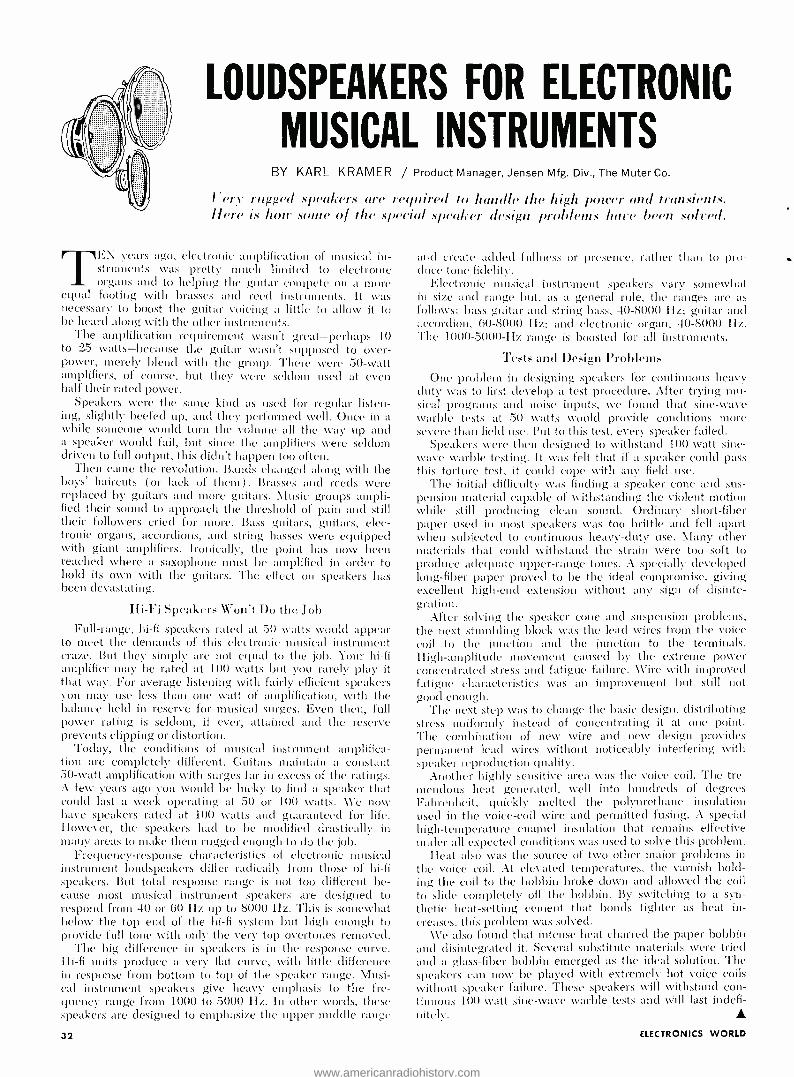
LOUDSPEAKERS FOR ELECTRONIC
MUSICAL INSTRUMENTS BY KARL KRAMER / Product Manager, Jensen Mfg. Div., The Muter Co.
Very rugged speakers are required to handle the high power merl transients. Here is how some of the special .speaker design problems hate been sol'ed.
Tf.N years ago, electronic amplification of musical in- struments was pretty much limited to electronic organs and to helping the guitar compete on a more
equal footing with brasses and reed instruments. It was necessary to boost the guitar voicing a little to allow it to be heard along with the other instruments.
The amplification requirement wasn't great- perhaps 10 to 25 watts- because the guitar wasn't supposed to over- power, merely blend with the group. There were 50 -watt amplifiers, of course, but they were seldom used at even half their ratted power.
Speakers were the same kind as used for regular listen- ing, slightly beefed up, and they performed well. Once in a while someone would turn the volume all the way up and a speaker would fail, but since the amplifiers were seldom driven to full output, this didn't happen too often.
Then came the revolution. Bands changed along with the boys' haircuts (or lack of them) . 13rasses and reeds were replaced by guitars and more guitars. Alusic groups ampli- fied their sound to approach the threshold of pain and still their followers cried for more. Bass guitars, guitars, elec- tronic organs, accordions, and string basses were equipped with giant amplifiers. Ironically, the point has now been reached where a saxophone must be amplified in order to hold its own with the guitars. The effect on speakers has been devastating.
IIi -Fi Speakers Won't Do the Job Full- range, hi -fi speakers rated at 50 watts would appear
to meet the demands of this electronic musical instrument craze. But they simply are not equal to the job. Your hi -fi amplifier may be rated at 100 watts but you rarely play it that way. For average listening with fairly efficient speakers you may use less than one watt of amplification, with the balance held in reserve for musical surges. Even then, full power rating is seldom, if ever, attained and the reserve prevents clipping or distortion.
Today, the conditions of musical instrument amplifica- tion are completely different. Guitars maintain a constant 50 -watt amplification with surges far in excess of the ratings. A few years ago you would be lucky to find a speaker that could last a week operating at 50 or 10O watts. AVe now have speakers rated at 100 watts and guaranteed for life. However, the speakers liad to be modified drastically in many areas to make them rugged enough to do the job.
Frequency- response characteristics of electronic musical instrument loudspeakers differ radically from those of hi -fi speakers. But total response range is not too different be- cause most musical instrument speakers are designed to respond from 40 or 60 Hz up to 8000 Hz. This is somewhat below the top end of the hi -fi system but high enough to provide full tone with only the very top overtones removed.
The big difference in speakers is in the response curve. Hi -fi units produce a very flat curve, with little difference in response from bottom to top of the speaker range. Musi- cal instrument speakers give heavy emphasis to the fre- quency range from 1000 to 5000 Hz. In other words, these speakers are designed to emphasize the upper middle range
32
and create added fullness or presence, rather than to pro- duce tone fidelity.
Electronic musical instrument speakers vary somewhat in size and range but, as a general rule, the ranges are as follows: bass guitar and string bass, 40 -8000 Hz; guitar and accordion, 00 -8000 Hz; and electronic organ, 40 -8000 Hz. The 1000 -5000 -Hz range is boosted for all instruments.
Tests and Design Problems One problem in designing speakers for continuous heavy
duty was to first develop a test procedure. After trying mu- sical programs and noise inputs, we found that sine -wave warble tests at 50 watts would provide conditions more severe than field use. Put to this test, every speaker failed.
Speakers were then designed to withstand 100 -watt sine - wave warble testing. It was felt that if a speaker could pass this torture test, it could cope with any field use.
The initial difficulty was finding a speaker cone and sus- pension material capable of withstanding the violent motion while still producing clean sound. Ordinary short -fiber paper used in most speakers was too brittle and fell apart when subjected to continuous heavy -duty use. Many other materials that could withstand the strain were too soft to produce adequate upper -range tones. A specially developed long -fiber paper proved to be the ideal compromise, giving excellent high -end extension without any sign of disinte- gration.
After solving the speaker cone and suspension problems, the next stumbling block was the lead wires from the voice coil to the junction and the junction to the terminals. High- amplitude movement caused by the extreme power concentrated stress and fatigue failure. \Vire with improved fatigue characteristics was an improvement but still not good enough.
The next step was to change the basic design, distributing stress uniformly instead of concentrating it at one point. The combination of new wire and new design provides permanent lead wires without noticeably interfering with speaker reproduction quality.
Another highly sensitive area was the voice coil. The tre- mendous heat generated, well into hundreds of degrees Fahrenheit, quickly melted the polyurethane insulation used in the voice -coil wire and permitted fusing. A special high -temperature enamel insulation that remains effective under all expected conditions was used to solve this problem.
Heat also was the source of two other major problems in the voice coil. At elevated temperatures, the varnish hold- ing the coil to the bobbin broke down and allowed the coil to slide completely off the bobbin. By switching to a syn- thetic heat -setting cement that bonds tighter as heat in- creases. this problem was solved.
We also found that intense heat charred the paper bobbin and disintegrated it. Several substitute materials were tried and a glass -fiber bobbin emerged as the ideal solution. The speakers can now be played with extremely hot voice coils without speaker failre. These speakers will wfthstand con- tinuous 100 -watt sine -wave warble tests and will last indefi- nitely.
ELECTRONICS WORLD
www.americanradiohistory.com
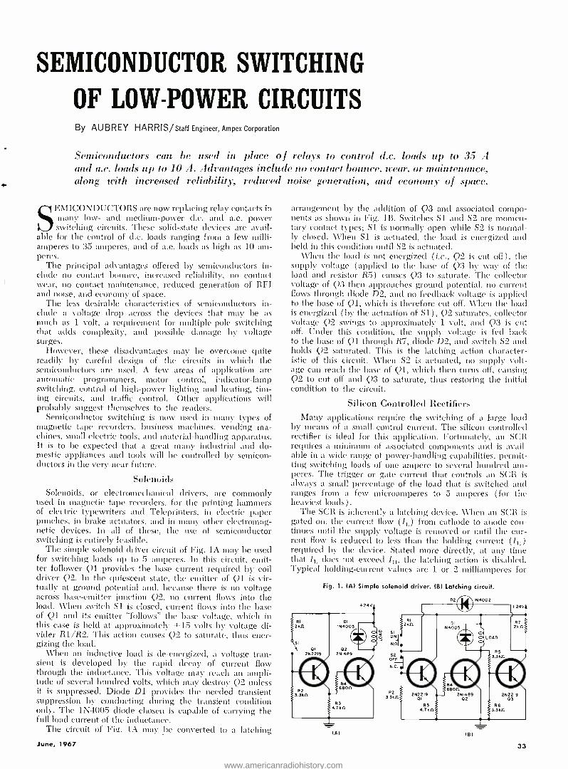
SEMICONDUCTOR SWITCHING
OF LOW -POWER CIRCUITS By AUBREY HARRIS /Staff Engineer, Ampex Corporation
Semiconductors can be used in place of relays to control d.c. loads up to 35 A and a.c. loads up to 10 A. Advantages include no contact bounce. wear, or maintenance, along with increased reliability, reduced noise generation, and economy of space.
SEMICONDUCTORS are now replacing relay contacts in many low- and medium -power d.c. and a.c. power switching circuits. These solid -state devices are avail-
able for the control of d.c. loads ranging from a few milli- amperes to 35 amperes, and of a.c. loads as high as 10 am- peres.
The principal advantages offered by semiconductors in- clude no contact bounce, increased reliability, no contact wear, no contact maintenance, reduced generation of RFI and noise, and economy of space.
The less desirable characteristics of semiconductors in- clude a voltage drop across the devices that may be as much as 1 volt, a requirement for multiple -pole switching that adds complexity, and possible damage by voltage surges.
However, these disadvantages may be overcome quite readily by careful design of the circuits in which the semiconductors are used. A few areas of application are automatic programmers, motor control, indicator -lamp switching, control of high -power lighting and heating, tim- ing circuits, and traffic control. Other applications will probably suggest themselves to the readers.
Semiconductor switching is now used in many types of magnetic tape recorders, business machines, vending ma- chines, small electric tools, and material -handling apparatus. It is to be expected that a great many industrial and do- mestic appliances and tools will be controlled by semicon- ductors in the very near future.
Solenoids Solenoids, or electromechanical drivers, are commonly
used in magnetic tape recorders, for the printing hammers of electric typewriters and Teleprinters, in electric paper punches, in brake actuators, and in many other electromag- netic devices. In all of these, the use of semiconductor switching is entirely feasible.
The simple solenoid driver circuit of Fig. lA may be used for switching loads up to 5 amperes. In this circuit, emit- ter follower Q1 provides the base current required by coil driver Q2. In the quiescent state, the emitter of Ql is vir- tually at ground potential and, because there is no voltage across base- emitter junction Q2, no current flows into the load. When switch S1 is closed, current flows into the base of Q1 and its emitter "follows" the base voltage, which in this case is held at approximately +15 volts by voltage di- vider R1 /R2. This action causes Q2 to saturate, thus ener- gizing the load.
When an inductive load is de- energized, a voltage tran- sient is developed by the rapid decay of current flow through the inductance. This voltage may reach an ampli- tude of several hundred volts, which may destroy Q2 unless it is suppressed. Diode D1 provides the needed transient suppression by conducting during the transient condition only. The 1N4005 diode chosen is capable of carrying the full load current of the inductance.
The circuit of Fig. lA may be converted to a latching
June, 1967
arrangement by the addition of Q3 and associated compo- nents as shown in Fig. lß. Switches Si and S2 are momen- tary contact types; S1 is normally open while S2 is normal- ly closed. When Si is actuated, the load is energized and held in this condition until S2 is actuated.
When the load is not energized ( i.e., Q2 is cut off) , the supply voltage (applied to the base of Q3 by way of the load and resistor R5) causes Q3 to saturate. The collector voltage of Q3 then approaches ground potential, no current flows through diode D2, and no feedback voltage is applied to the base of Q1, which is therefore cut off. When the load is energized (by the actuation of S1), Q2 saturates, collector voltage Q2 swings to approximately 1 volt, and Q3 is cut off. Under this condition, the supply voltage is feci back to the base of Q1 through R7, diode D2, and switch S2 and holds Q2 saturated. This is the latching action character- istic of this circuit. When S2 is actuated, no supply volt- age can reach the base of Q1, which then turns off, causing Q2 to cut off and Q3 to saturate, thus restoring the initial condition to the circuit.
Silicon Controlled Rectifiers Many applications require the switching of a large load
by means of a small control current. The silicon controlled rectifier is ideal for this application. Fortunately, an SCR requires a minimum of associated components and is avail- able in a wide range of power -handling capabilities, permit- ting switching loads of one ampere to several hundred am- peres. The trigger or gate current that controls an SCR is always a small percentage of the load that is switched and ranges from a few microamperes to 5 amperes ( for the heaviest loads) .
The SCR is inherently a latching device. When an SCR is gated on, the current flow (IL) from cathode to anode con- tinues until the supply voltage is removed or until the cur- rent flow is reduced to less than the holding current (Irk) required by the device. Stated more directly, at any time that Ir, does not exceed Iir, the latching action is disabled. Typical holding- current values are 1 or 2 milliamperes for
Fig. 1. (A) Simple solenoid driver. (B) Latching circuit.
la!
si
oN 0,
52 OFF
N.C.
R2 33kn
tel
33
www.americanradiohistory.com

SCR Type
Number Forward Blocking Voltage (Wolf)
(volts)
R.M.S. Forward Current (le)
(amperes)
Forward Blocking
Current (11:x)
(microamperes)
Holding Current (1111
(milliamperes)
Gate Tri7Jor Current (LT)
(milliamperes)
Gate Trigger Voltage (V,.r)
(volts)
2N2323 (C5F) 50 1.6 2 - 10 1 - 2 .01 - .2 .5 - .8
2N2323A 50 1.6 2 - 10 1 - 2 .002 - .02 .4 - .6
2N2326 (C5B) 200 1.6 2 - 10 1 - 2 .01 - .2 .5 - .8
C22F 50 7.4 1000 - 10000 10 - 30 4 - 25 .8 - 1.5
2N688 400 35 6500 1 0 - 100 1 5 - 40 1 .5 - 3.0
Table 1. Useful design characteristics of a group of typical silicon controlled rectifiers.
a 1.6- ampere device, and 10 to 30 milliamperes for a 7.4- ampere device. (Table 1 includes the more useful design characteristics of typical SCR's.)
The basic latching circuit of an SCR is shown in Fig. 2A. When momentary contact switch Si is actuated, a pulse of the gate voltage (Ve) is applied to gate terminal G, causing the SCR to saturate. The gate voltage may range from +3 to +6 volts; the minimum gate current for a sensitive, low - current SCR (e.g., the 2N2323A) is on the order of 10 to 200 microamperes. The SCR will remain saturated until the power supply is disconnected. Because removal of the pow- er supply involves handling the total current required by the load, other means of reducing Ir, to a level below Ili are necessarily employed.
The latching circuit shown in Fig. 2B provides controlled turnoff by the addition of commutating capacitor C and switch S2. The SCR is gated on by the momentary actua- tion of switch Si, causing the potential at point A to swing to approximately 1 volt above ground. Capacitor C then charges from the power supply through R2. When C is fully charged, the voltage at point B is positive with respect. to point A by the difference between the supply voltage and the voltage drop across the SCR.
The SCR is turned off by actuation of switch S2, which grounds point B, causing the charge on capacitor C to decay toward ground potential. Because C cannot discharge in- stantly, the potential at point A swings below ground po-
TURN -ON GATE PULSE
V, 310 RV
Im..+- (MINI
GATE VOLTAGE S
Vv
}
R un
+24V It.
*REQUIRED ONLY IF LOAD IS INDUCTIVE
(A)
-'1N4005
lBl
Fig. 2. (Al Basic SCR latching circuit. IBI An SCR latching circuit using a commutating capacitor to assist operation.
Fig. 3. (A) Load control by remote power feed. IBI A load control which provides turn -off of load power at some pre- determined time interval following the turn on (via R2).
REMOTE AREA
RI
4.71111
SI ON
52 OFF rÎ
34
LOAD AREA
+29V -A- - LOAD
SCR2 C22F
R4 I11Il
II
R2 IAn
1C3
IyF
C2.
IyF
SCRI CSF
+24V R3 I 4 nnnnnnv . I 221111
(Al
3.3yF
r51 ON
GATE VOLTAGE
IBl
tential by the amount of the charge, causing the anode of the SCR to be negative with respect to the cathode. The result is that the SCR turns off and remains off until another gate pulse is applied.
The approximate capacitance (in microfarads) of com- mutating capacitor C may be computed by the formula C = (1.5t0ffl,) /V where V is the supply voltage, IL is the load current in amperes, and toff is the turnoff time of the SCR in microseconds.
In the typical case where the supply voltage is 24 volts, the load current is 1 ampere, and the SCR turnoff time is 50 microseconds, the computation is C = (1.5 X 50 X 1) / 24 = 3.1 µF.
In practice, the next larger standard value of 3.3 cF is selected. The resistance of R2 is not critical; a typical choice of resistance is in the range of 10,000 to 100,000 ohms.
A variation of the SCR latching circuit of Fig. 2B appears in Fig. 3A. The principal differences include the addition of low -power SCR1 and the use of normally closed (instead of normally open) momentary contact switches. The ca- pacitance of commutating capacitor Cl remains unchanged at 3.3 1.LF.
When switch Si ( "On ") is actuated, load SCR2 is gated on from the power -supply voltage through R1 and normally closed switch S2. Capacitor Cl then charges between ground (through SCR2) and the supply voltage through R3. When switch S2 ( "Off ") is actuated, SCR1 is gated on and commu- tating capacitor Cl lowers the anode voltage of SCR2, which turns off SCR2. Capacitor Cl then charges in the opposite direction between ground (through SCR1 ) and the supply voltage through the de- energized load. When Si ( "On ") is again actuated, the cycle just described is repeated. It is thus apparent that SCR1 and SCR2 operate in flip /flop action so that when one is conducting, the other is cut off.
The resistance of R3 is calculated by the formula (1 /50) (V101 Fx /Ir,.,,) where V121 Fx is the forward breakover voltage in volts and Il.,,, is the leakage current in amperes.
Capacitors C2 and C3 prevent noise pulses in the remote gate lines from inadvertently firing SCR1 or SCR2. If switches S1 and S2 are actuated during an overlapping period of time, the first one depressed may affect the states of SCR1 or SCR2, but the second one depressed will have no effect until the other is released. If both are depressed simultaneously, no trigger pulses will be generated and the states of SCR1 and SCR2 will not be affected.
The circuit of Fig. 3B provides the feature of an ad- justable period during which the load is energized by a trigger pulse. When switch Si is actuated, SCR1 is gated on and the load is energized. Commutating capacitor Cl then charges between ground (through SCR1) and the sup- ply voltage through Rl, and SCR2 is turned off. Under this condition, relaxation oscillator UJT produces one cycle of oscillation, the duration of which is a direct function of the setting of variable resistor R2. At the conclusion of the cycle, SCR2 is gated on by the pulse formed across resistor R4, the UJT is disabled, and SCR1 is turned off by the charge on Cl.
An SCR is also useful as a lamp driver. In this applica- tion the SCR controls a bank of high- wattage lamps by
ELECTRONICS WORLD
www.americanradiohistory.com

means of a small amount of gate power. For instance, a 2N688 will handle a load of 35 amperes r.m.s. up to a peak of 400 volts by means of a gate drive of 3 volts at 40 milliamperes (see Fig. 4A) .
Because an SCR is a unidirectional device, the lamp pow- er must be full -wave rectified a.c. However, the resulting pulsating d.c. waveform is not filtered because the return of each positive excursion to zero volts is useful when the lamps are to be turned off.
The positive gate voltage is applied to the SCR gate by the closing of switch Si. When the lamps are to be turned off, S1 is opened, and the lamps are de- energized at the next return to zero of the d.c. waveform.
Triacs The gated bi- directional controlled rectifier (or the gate -
controlled a.c. switch) is a recent development in the field of SCR design and is known as a Triac. This device is capable of switching a.c. loads as high as 400 volts at 10 amperes and may be used in parallel for higher current loads. (Table 2 includes the more useful design character- istics of typical gate -controlled a.c. switches.)
The Triac may be gated on by either a negative or a pos- itive voltage and will conduct until the end of the half cycle during which the gate drive is removed (or until the a.c. power is disconnected) . The basic application (see Fig. 413) uses a d.c. gate voltage (Vg) ; the Triac conducts dur- ing both the positive or the negative excursion of the sine - wave power. Polarity of the gate drive is not significant.
In order to drive an a.c. motor or device, the power line itself may be used as a trigger to cause the Triac to deliver a.c. power to the load. The basic circuit of this applica- tion appears in Fig. 4C. Assume that the initial conditions are that a.c. power is present, the Triac is not con- ducting, and point L is positive with respect to point M. At this time, the full supply power is applied to the Triac, and point A2 is positive with respect to point Al. If switch Si is then closed, current will flow through R1 (and Si) to gate terminal G, which will turn on the Triac. The poten- tial between Al and A2 will then drop to a very low value that will cause the flow of gate current to cease. The Triac will conduct through the half- cycle, cut off momentarily at the zero crossover of the power -supply waveform, and resume conduction as soon as the opposite excursion of the waveform has started. This cycle of events will repeat as long as switch Si remains closed. When S1 is opened, the Triac will cut off at the next zero crossover of the wave- form and remain off until Si is again closed.
It is often necessary to isolate the control circuit from a line- operated load. Fig. 5A illustrates one means of pro- viding this isolation by the use of a grounded relaxation oscillator and a small 1:1 pulse transformer. The gate and terminal Al of the Triac are connected to opposite termi- nals of the Ti secondary winding. Components R1, Cl, Q1, R2, and the primary winding of T1 form the UJT relaxation oscillator.
Under initial conditions, switch S1 is open, the relaxa- tion oscillator is dormant, the power -line voltage is present,
Table 2. Useful design characterist:cs o.
(B) (C)
Fig. 4. (AI Basic application of SCR in a lamp- driver dr- cuit. (BI Basic application of a gated bi- directional con- trolled rectifier. IC) The power line triggers the gated bi- directional controlled rectifier when switch S1 closes.
OM- +IOV
orr -0v CONTROL
k VOLTAGE
SI
RI 4.741k1.11
CI 0.2pF
IOA (MALI +20V
R2 15011
RI Icon
R2
262647 OI
(A)
TRIAC SC450
(B)
Fig. 5. IA) Low current isolated control of a large power load. (B1 Triac connected in a typical latching circuit.
the Triac is not conducting, and the load is not energized. When Si is closed, the oscillator begins generation of its nominal frequency which may be in the range of 600 to 6000 Hz. The resulting pulses are coupled through T1 to the gate of the Triac. The first pulse received causes the Trac to saturate during the remainder of the first half -cycle of power; succeeding pulses within this period are ignored. At the first zero crossover of the power waveform, the Triac cuts off momentarily but is triggered on again by the first pulse received after the next half -cycle of power begins. This action repeats as long as switch Si remains closed. Obviously, slightly more of the full waveform of the line power will be delivered to the load if the oscillator operates in the region of 6000 Hz rather than in the region of 600 Hz because the off time at the zero crossover will be slight- ly more brief.
A Triac may be connected in a latching circuit as shown in Fig. 5B. Assuming that the Triac is initially cut off, if Si is closed, current will flow through R1 and R2 to the gate and the Triac will saturate. During the first half -cycle of the power waveform, capacitor Cl charges through R2 and the Triac toward the load voltage; at the end of the half- cycle, capacitor Cl discharges through the gate, which triggers the Triac into saturation for the next half- cycle. This process continues until S2 is closed, which causes Cl to discharge through the load, leaving no current flow through the gate. The Triac then cuts off at the next zero crossover of the power waveform and remains off until S1 is again operated.
typical gate -controlled a.c. switches (Triacs)
Triac Type Number
Forward Blocking Voltage (VF1151)
(volts)
R.M.S. Forward Current (IF) (amperes)
Holding Current (Ill)
(milliamperes)
Gate Trigger Current IIGT) (milliamperes)
Gate Trigger Voltage )V(,T)
(volts)
Manufacturer
SC 40 B 200 6 25 - 50 25 - 100 1.5 - 3.0 G -E SC 45 8 200 10 25 - 50 25 - 100 1.5 - 3.0 G -E SC 45 D 400 10 25 - 50 25 - 100 1.5 - 3.0 G -E
TA 2892 100 2.5 1 - 5.5 1 - 4.5 1 - 2.6 RCA TA 2893 200 2.5 1 - 5.5 1 - 4.5 1 - 2.6 RCA TA 2918 200 6 5 - 36 15 - 35 1 - 2.4 RCA TA 2919 400 6 5 - 36 15 - 35 1 - 2.4 RCA
rle, :967 35
www.americanradiohistory.com

Fig. 1. The automatic keyer used at WB2KYF consists of a
Digiac 3080 computer and electric typewriter coupled to the transmitter or code oscillator via transistor connection box.
The Penultimate Automatic Keyer By PETER A. STARK, K20AW, STEPHEN GORDON, WA2CPE and ANTHONY MANFREDONIA
Dept. of Electrical Technology, Queensborough Community College
Ting a digital computer to a hang transmitter or code oscillator may be an expensive way to add an automatic electronic keyer; however, this setup not only sends code but it can also practically conduct the entire ()SO.
HERE is an automatic kever that does almost every- thing but tune up the rig and think. It not only com- pletes dots and clashes (as any good kever should),
but also forms complete letters, words, and sentences auto- matically. It has an internal memory that can store entire sentences and paragraphs, such as 9TH descriptions, and can transmit them at will. The input into the keyer is from an electric typewriter, with Morse code generated entirely by the kever at any speed from 1 /10 to 100 words- per -min- ute. It can even generate start -stop teletypewriter code.
The heart of the kever is a digital computer, which is coupled to the transmitter through a simple transistorized connection box. The unit, shown in Fig. 1, is the kever we have set up at \\"132KYF, the club station at Queensborough Community College of the City University of New York.
The computer used in our installation is the DE3080 made by Digital Electronics. Although this particular computer costs about 820,000, the kever can also use the 510,000 PDP -8S computer, made by Digital Equipment Corp. The PDP -8S is substantially faster and can easily reach 100 words - per- minute speeds, while our DE3080 is presently somewhat slower.
The price of 810,000 for a mere automatic kever may seem somewhat steep, even considering its features. But re- member that the kcyer can also do other things. In its spare time, the computer can balance the YL's checkbook, do the junior op's homework, or play tic -tac -toe with your neighbor. During a dull party it makes an excellent conversation piece, and can even be taught to tell your guests things you would never dare tell them yourself!
The Digital Computer As mentioned earlier, the heart of the keyer is the digital
computer. Since this is a new piece of gear in the ham shack, let us spend a little time describing it.
A digital computer is really nothing but a lightning -fast calculator with a memory for numbers and instructions. By means of these instructions, it can go through a long pro- cedure which can be quite involved. The typical computer
36
has five basic sections, shown in Fig. 2. These are called the input unit, the memory unit, the output unit, the arith- metic unit, and the control unit.
The input unit is used to feed information into the com- puter. On our computer it consists of an electric typewriter, a punched paper tape reader, and a card reader.
The memory unit is used to store information fed into the computer through the input unit. Each separate piece of in- formation is located in a specific place in the memory. To keep the information straight, each of these locations in the memory has an address, which is used to identify what is where. The computer used at \y'132KYF has 4096 separate memory locations. Since each location can store up to four letters, numbers, or punctuation marks, this means we can store over 16 thousand letters in the memory. But since the instructions telling the computer what to do are also stored in the memory, the space left for words is somewhat less. Still, this is quite an impressive storage for useful informa- tion. We could, for example, store an entire page from a telephone book in the memory and transmit it, without error, at any code speed beyond the ability of any operator to copy. Great for the times when you cannot think of any- thing else to say!
The output unit of our computer is normally the electric typewriter and a paper tape punch; in addition, the lights on the control panel shown in Fig. 1 can also be used for output. In order to use the computer to generate Morse code, we have to add another output circuit to energize a fast relay to key the transmitter. The most efficient way to do this would be to dig into the computer and modify the cir- cuits. 131t since this is likely to void the guarantee, there is an easier way. Since the lights on the control panel can be used for output, it is simple to connect the code output circuitry directly across the lamp bulbs.
The arithmetic unit of a computer can take numbers from the memory and perform simple operations like addition, subtraction, division, and multiplication. The results can then be fed into the memory and saved for later calculations, or can be fed out through the output unit.
ELECTRONICS WORLD
www.americanradiohistory.com
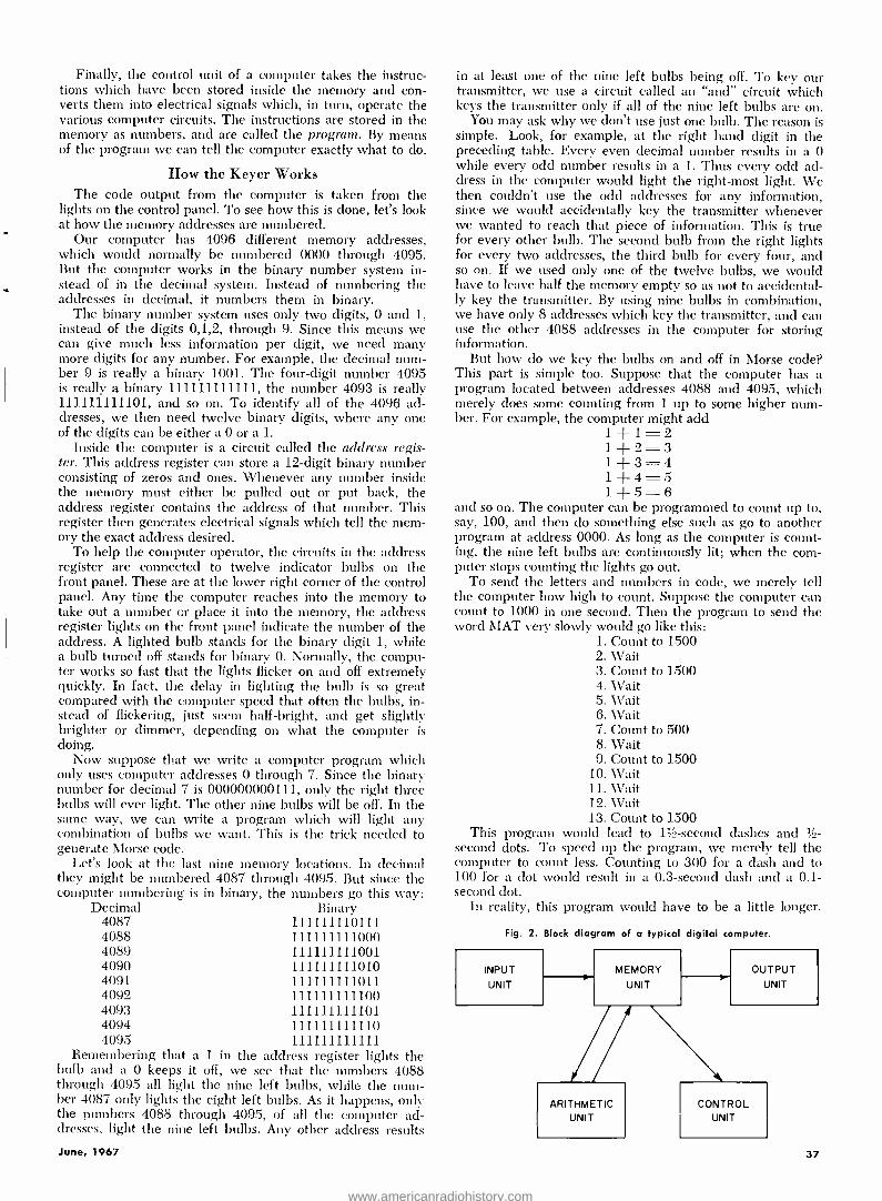
Finally, the control unit of a computer takes the instruc- tions which have been stored inside the memory and con- verts them into electrical signals which, in turn, operate the various computer circuits. The instructions are stored in the memory as numbers, and are called the program. By means of the program we can tell the computer exactly what to do.
How the Keyer Works The code output from the computer is taken from the
lights on the control panel. To see how this is done, let's look at how the memory addresses are numbered.
Our computer has 4096 different memory addresses, which would normally be numbered 0000 through 4095. But the computer works in the binary number system in- stead of in the decimal system. Instead of numbering the addresses in decimal, it numbers them in binary.
The binary number system uses only two digits, 0 and 1, instead of the digits 0,1,2, through 9. Since this means we can give much less information per digit, we need many more digits for any number. For example, the decimal num- ber 9 is really a binary 1001. The four -digit number 4095 is really a binary 111111111111, the number 4093 is really 111111111101, and so on. To identify all of the 4096 ad- dresses, we then need twelve binary digits, where any one of the digits can be either a 0 or a 1.
Inside the computer is a circuit called the address regis- ter. This address register can store a 12 -digit binary number consisting of zeros and ones. Whenever any number inside the memory must either be pulled out or put back, the address register contains the address of that number. This register then generates electrical signals which tell the mem- ory the exact address desired.
To help the computer operator, the circuits in the address register are connected to twelve indicator bulbs on the front panel. These are at the lower right corner of the control panel. Any time the computer reaches into the memory to take out a number or place it into the memory, the address register lights on the front panel indicate the number of the address. A lighted bulb stands for the binary digit 1, while a bulb turned off stands for binary 0. Normally, the compu- ter works so fast that the lights flicker on and off extremely quickly. In fact, the delay in lighting the bulb is so great compared with the computer speed that often the bulbs, in- stead of flickering, just seem half- bright, and get slightly brighter or dimmer, depending on what the computer is doing.
Now suppose that we write a computer program which only uses computer addresses 0 through 7. Since the binary number for decimal 7 is 000000000111, only the right three bulbs will ever light. The other nine bulbs will be off. In the same way, we can write a program which will light any combination of bulbs we want. This is the trick needed to generate Morse code.
Let's look at the last nine memory locations. In decimal they might be numbered 4087 through 4095. But since the computer numbering is in binary, the numbers go this way:
Decimal Binary 4087 111111110111 4088 111111111000 4089 111111111001 4090 111111111010 4091 111111111011 4092 111111111100 4093 111111111101 4094 111111111110 4095 111111111111
Remembering that a 1 in the address register lights the bulb and a 0 keeps it off, we see that the numbers 4088 through 4095 all light the nine left bulbs, while the num- ber 4087 only lights the eight left bulbs. As it happens, only the numbers 4088 through 4095, of all the computer ad- dresses, light the nine left bulbs. Any other address results
in at least one of the nine left bulbs being off. To key our transmitter, we use a circuit called an "and" circuit which keys the transmitter only if all of the nine left bulbs are on.
You may ask why we don't use just one bulb. The reason is simple. Look, for example, at the right hand digit in the preceding table. Every even decimal number results in a 0 while every odd number results in a 1. Thus every odd ad- dress in the computer would light the right -most light. We then couldn't use the odd addresses for any information, since we would accidentally key the transmitter whenever we wanted to reach that piece of information. This is true for every other bulb. The second bulb from the right lights for every two addresses, the third bulb for every four, and so on. If we used only one of the twelve bulbs, we would have to leave half the memory empty so as not to accidental- ly key the transmitter. By using nine bulbs in combination, we have only 8 addresses which key the transmitter, and can use the other 4088 addresses in the computer for storing information.
But how do we key the bulbs on and off in Morse code? This part is simple too. Suppose that the computer has a program located between addresses 4088 and 4095, which merely does some counting from 1 up to some higher num- ber. For example, the computer might add
1+1 =2 ] +2 =3 1 +3 =4 1 + 4 = 5 1 + 5 = 6
and so on. The computer can be programmed to count up to, say, 100, and then do something else such as go to another program at address 0000. As long as the computer is count- ing, the nine left bulbs are continuously lit; when the com- puter stops counting the lights go out.
To send the letters and numbers in code, we merely tell the computer how high to count. Suppose the computer can count to 1000 in one second. Then the program to send the word MAT very slowly would go like this:
1. Count to 1500 2. Wait 3. Count to 1500 4. Wait 5. Wait 6. Wait 7. Count to 500 8. Wait 9. Count to 1500
10. Wait 11. Wait 12. Wait 13. Count to 1500
This program would lead to PA- second dashes and 1/2-
second dots. To speed up the program, we merely tell the computer to count less. Counting to 300 for a dash and to 100 for a dot would result in a 0.3- second dash and a 0.1- second dot.
In reality, this program would have to be a little longer.
Fig. 2. Block diagram of a typical digital computer.
INPUT
UNIT
MEMORY
UNIT
ARITHMETIC UNIT
OUTPUT UNIT
CONTROL UNIT
June, 1967 37
www.americanradiohistory.com

We would also have to change the length of the wait inter- vals depending on code speed. Then there would have to be a program to recognize the letters typed on the typewriter and translate them into the proper instructions to send the code, or to take whole sentences out of memory and convert them into the instructions needed to get the code. This is an interesting project in itself. But since it depends on the exact computer you use to build your penultimate automatic key - er, we won't go into it here.
You will notice that a simple change of program can also change the code. Since the program is stored in the comput- er's memory and placed there just by typing it on the type- writer, we do not have to change any wiring to get the differ- ent code. We can easily get any code we want. By typing in a new program, we can get teletypewriter code.
How to Connect to the Computer The keying portion of the keyer connects to the nine left
bulbs on the address part of the control panel. This connec- tion is made in such a way that the keying relay closes only if all of these lights are on.
Fig. 3 shows how the lights are connected inside a typical computer. Each bulb is in the collector circuit of a transistor; if the transistor is turned off, the light is also off. If the tran- sistor is on, the light is on. In this way, the transistor acts like a switch to turn the light on and off.
When the transistor is on and acts as a short circuit to the lamp current, the voltage at the collector is very low -quite close to 0 volts. When the transistor is open and there is no lamp current, the collector voltage is about -10 volts (as- suming p -n -p transistors and a -10 -volt supply). The col- lector voltage then indicates whether the bulb is on or off.
IOk
TO KEYER CIRCUIT
-10V IF BULB IS OFF
OV IF BULB IS ON
Fig. 3. Indicator driver cir- cuit feeding indicator lamp.
Fig. 4. "And" circuit used to sense which lamps are on and drive the keying relay (5000 -ohm, 1.4 -mA pull -in radio -control type).
-15V 0
10k
2N404
Ik
4.7k
ANY LOW -POWER SILICON DIODE
2N404
IOyF I+ 6V
FROM FROM FROM IST 2ND 3RD
BULB BULB BULB
o FROM 4TH BULB
KEYING RELAY (LAFAYETTE 99C6091)
ANY LOW -POWER SILICON DIODES
Ik
FROM FROM FROM 5TH 6TH 7TH
BULB BULB BULB
FROM 8TH
BULB
FROM 9TH
BULB
NINE IN914 DIODES
38
To monitor the nine left -most bulbs in the address regis- ter, we feed the signal from the nine indicator driver tran- sistors to a circuit called an "and" gate. The word "and" im- plies that we get an output from the circuit only if the first signal is there, "and" the second signal is there, "and" the third signal is there, "and" so forth. The "and" circuit driving the relay is shown in Fig. 4.
The nine signals from the indicator driver transistors are connected to nine diodes. Let's assume that some of the nine bulbs are off. Then some of the inputs to the diodes are negative. Since this makes the cathode of the correspond- ing diode negative, this diode conducts through the two 10,000 -ohm resistors to ground. This places a negative volt- age on the base of the first transistor. The first transistor is therefore on and its collector voltage drops to a low value. Asa result, the base of the second transistor drops toward zero volts and the transistor trolls off. This opens the relay used for keying.
If, on the other hand, all nine lights are on, then all of the inputs to the "and" circuit are about 0 volts. Since this takes away the negative bias from the first transistor, the transistor is off. Its collector voltage then becomes negative and provides a negative bias to the second transistor. This closes the relay. In this way we control the relay; if all of the lights are on, the relay closes, but if any one (or all) of the nine lights goes off, the relay opens.
This is all there is to the operation of the circuit. To make sure the circuit works reliably, we add a few more parts. The diode across the relay coil prevents a voltage spike, gener- ated when the relay opens, from burning out the transistor. The 10- microfarad capacitor and two diodes in the emitter circuit provide a steady negative voltage drop of about 1 volt on the emitters of the transistors. This ensures that ground- ing the base of the transistor is enough to turn it off.
The 2N404 transistors are common medium -speed units used in digital circuits. They can handle relay coils which take up to 100 mA. A relay taking more current will require different transistors. If you plan to use this relay to generate teletypewriter code, a polar relay should be used. This is
because a normal relay, while fast enough to produce good Morse code, is not fast enough to produce accurate tele- typewriter code.
Operating the Keyer How well the keyer works depends on the power of the
computer and especially on whether the input and output units of the computer can work at the same time as the arithmetic and control units. If they can, then it is possible to sit at the typewriter and have the computer send out every letter as it is typed. If you type slowly, then the computer will have to wait for each letter. If you type quickly, on the other hand, the computer will send at the desired speed and merely store all unsent letters. A moderately fast typist can keep ahead of the computer as much as he wants, since the computer can store quite a backlog of information.
The computer used at WB2KYF, however, is a little more limited. It can either accept text from the typewriter or send out Morse code, but it cannot do both at the same time. For this reason we must first enter the text to be sent into the computer memory, and then send it out. Since we can prestore any number of messages, this is not nearly as bad as it might seem. A good operator can easily copy the other station and, at the same time, type the answers di- rectly into the computer for later transmission. ( Editor's Note: The computer described is used for instruction pur- poses, while the setup describer] is actually used for code practice sessions. In order to use the setup for on -the -air contacts, it would be better to have a computer that could key the transmitter at the same time that the message is being typed.)
The key to the successful use of the unit is in the pro- gramming, that is, in the instate- (Continued on page 74)
ELECTRONICS WORLD
www.americanradiohistory.com

HELP
ROADSIDE TRIGGERING
DEVICE
The Search for a
Highway Emergency Radio Program By ROBERT M. BROWN
The search is on for an electronic system to more automobile traffic with safety and speed. Here is a description of the HELP, REACT, CMG', RRA, and DAIR systems, along with some others that hare been tested in the past.
THE concept of a practical device for achieving radio communications between passenger car drivers and local authorities for purposes of routing, information,
and road service has long been under study by various groups in the automotive and two -way radio industries. Until recently, the project has lacked the momentum necessary to see it through. In the last few months, however, a com- bination of factors has resulted in a rebirth of the idea, and the race is now on for an acceptable industry -wide radio system. New ideas are appearing in Society of Automotive Engineers presentations, research and development depart- ment conferences, and technical journals, with the more dominant systems now being tested experimentally. At stake are automaker contracts, prestige, and, of course, a great deal of Federal aid.
While the newly formed National Motor Vehicle Safety Council promises to play a major role in the search for the best radio system, right now the FCC is getting most of the attention. This is due largely to its full -scale 1967 inquiry into "... how radio might be more effectively and efficiently used in the promotion of highway safety ".
Although it isn't known yet just how the final system will be integrated into the passenger car, there is consider- able talk in automotive circles that Washington may ul-
timately legislate the device as standard -equipment to be incorporated into all American production -line cars.
The "Communications Gap" Part of the motivation for the development of a highway
radio system seems to be the necessity for "... closing the communications gap on our national highways ". What is the "communications gap "? Fred Bauer of Ford's Radio En- gineering Division describes it as a period in time when communications have progressed `only to the point where the driver must still communicate by horn signals and rely almost entirely upon his eyes for a thousand details of the roadway ahead ". Eugene A. Hanvsz of General .ltutors' Re- search Laboratories puts it another way: "As vehicle popu- lation and traffic density continue to grow, the motoring public will demand assistance that goes beyond that of pres- ent sign techniques." Clearly these manufacturers are plan- ning now for such an eventuality.
The FCC gave interested parties until March 31, 1967 to file comments on which proposed highway emergency sys- tem they feel will be most effective. Explaining the Com- mission's involvement in something as far afield as highway safety, a December, 196(3 report stated that the "appalling" death rate on the nation's roadways requires that the agency
June, 1967 39
www.americanradiohistory.com

exercise its "broad authority . . . in the public interest ". Behind this activity is the Highway Safety Act of 1966
which provides 50 -50 matching funds for states and local communities "to expand and improve" their road safety pro- grams. In addition, it poses the threat of a 10% loss of Fed- eral highway construction funds for states which fail to comply. Included in the Act are improvements such as "electronic controls that convey regulatory or convenience information to motorists" as well as "statewide emergency medical services programs" that clearly call for mobile radio to do the job. The Department of Commerce's National Highway Safety Agency is supervising the drafting of uni- form standards for all the states, and the first suggestions were posted to representatives of the governors of the 50 states on February 16th of this year.
Industry Programs
Meanwhile, several industry -sponsored programs are re- ceiving attention, including the HELP and REACT projects which have been operational for a number of years. These programs have been joined by newcomers CRW, RRA, and DAIR, with more pouring in at the rate of better than one a month. (These highway radio systems will be described in detail further along in the article.) What makes them sig- nificant is that they have been developed and financed by some of the country's leading radio and automotive manu- facturers: Hallicrafters, Ford Motor Company, Motorola, and General Motors. In fact, an operational "radio highway" is now functioning with FCC approval between Detroit and Lansing, Michigan along Route I -96 to determine the feasi- bility of the Automotive Manufacturers Association's CB project.
Basic System Requirements The diversity of these programs may preclude any all -
encompassing description of their capabilities, but it is probably safe to say that each, to some extent, hopes to supply at least a few ingredients needed to effectively "close the gap ". All parties concerned are agreed that the re- quired technology is available; but until now necessary pub- lic information and promotion have been lacking.
What is needed is a reliable system that possesses several fundamental attributes: (1) it must have the ability to cov- er as much of the surfaced roadway in America as possible even though it might be initially implemented only in sprawling metropolitan areas; (2) it must be priced low enough to be practical from a long -range point of view; (3) it must furnish the driver with reliable two -way communi- cations at the flick of a switch; (4) it must be capable of providing accurate road information to the motorist in all kinds of weather; and (5) as Ford puts it, it must develop a sufficient "initial momentum of sizable proportions" to be put swiftly into operation on a national basis.
It is interesting to note that, almost without exception, the majority of participants so far reporting in with emer- gency system proposals are starting with 27-MHz Citizens Radio Service equipment. At present, nearly half of all the transmitters in the U nited States (including TV, broadcast,
Table 1. REACT statistics based on a recent system survey.
Organization:
Number of participating teams 1400
Average number of members per team 27
Total of active membership 40,000
Total CB'ers with REACT training 100,000
Messages:
Percentage of calls for road assistance 52.0%
Percentage of calls on actual accidents 21.4%
Total emergency situations handled monthly 50,238
Total emergency situations yearly 602,856
police, etc.) are crowded into the 11 -meter 27 -MHz CB band; yet, in spite of this congestion, CB persists as the overwhelm- ing choice. The reason for this is simple. Approximately three million transceivers have been sold to Americans anxious to provide themselves with vehicular communi- cations. And this fact becomes even more important when it is considered that these sales have been made without bene- fit of massive advertising campaigns. The consensus is that perhaps by sheer acceptance of CB, the public might pro- vide the required "momentum" to put the idea over.
Present Emergency Programs REACT. While the Hallicrafters- sponsored REACT (for
Radio Emergency Associated Citizens Teams) is not the most complex or sophisticated, it is easily the best example of what volunteer channel- monitoring can accomplish. Con- sisting of about 1400 244hour stations ready to provide CB channel -9 communications, augmented by a hard -core ac- tive membership of 40,000, REACT has handled over one million on- frequency requests for routing assistance, road service, and emergency aid ( ambulance, fire, police, etc.) .
( See Table 1.) When viewed in terms of a contender for a countrywide
motorist emergency service, however, its abilities pale in comparison with total needs. For true participation, the REACT member must be a licensed CB'er familiar with equipment limitations and have the conventional under -the- dash transceiver handy on all occasions. In addition, REACT is relatively unknown outside CB circles and it doesn't pre- tend to promise direct tie -ins with police, ambulance ser- vice, and gas station monitors. Even so, the fact remains that it is the only radio -aid system now in operation on a large scale in the United States.
HELP. In early 1965, the Automobile Manufacturers As- sociation announced the formation of project HELP (for Highway Emergency Locating Plan). Initially an extension of the REACT monitoring idea, HELP was promoted in several national magazines, in numerous radio broadcasts, and on more than 400 TV stations (which used an AMA film clip) . The idea was simply to equip the average motor- ist with inexpensive CB gear designed for single- frequency ( channel 9) operations.
It soon became apparent, however, that reliable, fool- proof enactment of the HELP concept required a shift from congested CB frequencies to those outside the service. In this manner, highway authorities and gas stations could monitor the channels without the annoyance of unrelated transmissions. To accomplish this, the A \IA petitioned the FCC for use of 27.235 and 27.245 MIIz.
Before acting on this petition, however, the Commission in late 1966 requested that a working model highway be set up for scrutiny. On December 1st, the first two -way emer- gency system along a public highway was established on Michigan's Route I -96. To obtain aid, a motorist simply puts though a call on channel 9; this is answered by any one of several service stations strategically situated along the ex- pressway. The results of this experiment, even though they will be incomplete in terms of the total HELP program, will be crucial to possible FCC endorsement of the AMA proposal.
Two other problems face the HELP proponents. First, the requested frequencies are not under the jurisdiction of the CRS ( FCC Rules, Part 95) ; and secondly, service ga- rages would stand to make a profit on the increased road calls. Both situations pose a serious threat to FCC approval, since enactment would require a major "exception" to nor- mal Commission policy in such rule- makings. The profit factor is particularly controversial, since it has been sug- gested that a surcharge be placed on all HELP calls to "help pay for the system ".
Even more important is the reaction of law- enforcement organizations that would be affected by the proposal. Many
40 ELECTRONICS WORLD
www.americanradiohistory.com
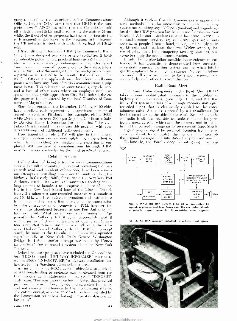
groups, including the Associated Police Communications Officers, Inc. (APCO), "aren't sure that HELP is the com- plete answer ". APCO has asked that the Commission hold off a decision on HELP until it can study the matter. Mean- while, the flood of other proposals has tended to stagnate the early momentum developed by the program. In the interim, the CB industry is stuck with a sizable carload of HELP sets.
CR\V. Although Motorola's CRW (for Community Radio Watch) was designed primarily as a crime- fighter, it holds considerable potential as a practical highway safety aid. The idea is to have drivers of radio- equipped vehicles report "suspicious and unusual" occurrences to their dispatchers, who, in turn, relay the message to police headquarters where a patrol car is assigned to the vicinity. Rather than confine itself to CB'ers, it is applicable on a local level to all com- panies who have any form of radio communications equip- ment in use. This takes into account taxicabs, dry cleaners, and a host of other users where an employer might re- spond to a civic -pride appeal from City Hall. Indeed, the en- tire program is administered by the local Chamber of Com- merce or \favor's office.
Since its inception in late December, 1966, over 100 cities have enrolled, each representing a significant number of signed -up vehicles. Pittsburgh, for example, claims 3000, while Detroit has over 6000 participants. Cincinnati's Safe- ty Director Henry J. Sandman has noted that `The . . .
Police Division could not duplicate this program with even $100,000 worth of additional radio equipment ".
How important a role CRW will play in the highway emergency system race depends solely upon the extent to which traffic accident and medical aid reporting is em- ployed. With any kind of promotion from this angle, CR\V may be a major contender for the most practical scheme.
Related Systems Falling short of being a true two -wary communications
system, yet still representing a means of furnishing the driv- er with road and accident information, have been numer- ous attempts at installing low -power transmitters along the highway. In the early 1950's, for example, the New York Port Authority used a 400 -watt AM transmitter feeding into a loop antenna to broadcast to a captive audience of motor- ists in the New York -bound lane of the Lincoln Tunnel. Every 2rí2 minutes a tape- recorded message was broadcast on 550 kHz which contained information and instructions; from time to time, authorities broke into the transmission to make emergency announcements. In 1952, however, the system was abandoned because, as one Port Authority of- ficial explained, "What can you say that's meaningful ?" Ap- parently the Authority felt it could accomplish what it wanted just as effectively with signs, although a similar sys- tem is reported to be in use now in Maryland by the Balti- more harbor Tunnel Authority. In the 1940's, a concept much the same as the Lincoln Tunnel idea was operated experimentally at New York City's George Washington Bridge. In 1959 a similar attempt was made by United International, Inc. to install a system along the New York Thruway.
Other broadcast proposals have included the General Mo- tors "HICOM" and "HIGH\VAY INFORMER" systems as well as 1966's "INFOMITTER," a highway installation des- ignated for the Smethport, Pennsylvania area.
An insight into the FCC's general objections to methods of Ai\I broadcasting to motorists can be gleaned from the Commission's denial statements in last year's "INFOMIT- TER" case. "Previous experience has indicated that practical problems ... arise." These include finding a clear frequency and not causing interference to the broadcasting service. The entire concept, as a matter of fact, has been regarded by the Commission recently as having a "questionable operat- ing status ".
June, 1967 41
Although it is clear that the Commission is opposed to sonic methods, it is also interesting to note that a unique system not requiring ally FCC policymaking and vaguely re- lated to the CRW program has been in use for years in New England. A Boston taxicab association has cone up with an unusual customer service. Any cab driver spotting an out- pouring of people ( from a hotel, movie, etc.) simply picks up his mike and broadcasts the news. Within seconds, doz- ens of cabs, many from competing taxi organizations, con- verge to supply the needed transportation.
In addition to alleviating possible inconvenience to cus- tomers, it has dramatically demonstrated how successful a central -frequency alerting system can be when intelli- gently employed to summon assistance. No relay stations are used. All cabs are tuned to the sane frequency and simply help each other to cover the town.
Radio Road Alert The Ford Motor Company's Radio Road Alert (RRA)
takes a more sophisticated approach to the problem of highway communications. ( See Figs. 1, 2, and 3.) Bas- ically, this system consists of a message memory unit (pre- recorded tape) that is electrically coupled to the enter- tainment radio. Action is triggered by a 100 -milliwatt (or less) transmitter at the side of the road. Even though the car radio is off, the roadside transmitter automatically in- jects a message code which sets the memory unit in action to find the correct message on its prerecorded tape. Should a higher priority signal be received (coming from a road crew up ahead, for example), the memory unit interrupts the original message and substitutes the preferred one.
Technically, the Ford concept is intriguing. For trig-
27- MH
RC VR - RESONANT
REED RELAY
DIODE GATING
AND LOGIC
DECODER
RELAY -e-
LOGIC
TAPE --. TRANSPORT
r PRIORITY
MESSAGE
OVERRIDE
MESSAGE - CHANNEL
SELECT
RADIO PARALLEL
AM BROADCAST INTERRUPT AND /OR -4 .- BROADCAST OF RRA
MESSAGE
l AM RADIO
AUDIO AMP
Fig. 1. When the RRA system picks up a one -coded CB signal, a prerecorded tape takes over the car radio. Should a priority signal come in, it overrides other signals.
Fig. 2. An RRA memory installed in vehicle trunk space.
SRKR,
www.americanradiohistory.com

Fig. 3. An experimental RRA roadside transmitter system. Permanent installation would be on high, fixed supports.
MODE SELECTOR POSITIONS v
L
I - AUDIO SIGNAL 2 - AID 3- CB CHANNEL 3 4 -CB CHANNEL 9
3
4 - --0 MODE
SELECTOR
I
A!D
MESSAGE ENCODER
CAR RADIO
CB
XMTR.
RELAY
CB
RCVR.
SPAR.
CONTROL
SIGN AND ROUTE
DECODER
CAR RADIO SPKR.
D. A. I. R. SPKR.
ROUTE CARD
SELECTOR
< AUDIO < ALERT
MAGNET SENSOR
SIGN AND
TURNS VISUAL DISPLAY
Fig. 4. The DAIR system uses either CB or signals from buried permanent magnets to activate the readout systems.
gering, the transmitted code first enters a resonant reed detector which, together with a diode -gating circuit, de- codes the message. A relay IC logic circuit usually blocks incoming codes, permitting the A \1 radio to operate nor- mally. When the proper code reaches the logic circuit, the tape -transport mechanism selects the correct message (pro- viding priority override if more than one code is received) and injects this into the AM set's audio circuit, (timing the
Fig. 5. Essential components of in -car DAIR system. Mes- sage readout (left), magnet sensor (bottom), and console. Console houses CB, magnetic logic, and signal processor.
42
car radio on at the same time (if it happens to be off). Conventional or standard car radio whips can be used
with matching transformers, eliminating the necessity for an additional receiving antenna. Directional transmitting antennas will be used to prevent confusion in cloverleaf areas. Ford feels that the tape -recorded message is superior to a direct /receive type in that "there is no possibility of static or other electrical disturbance" and the voice will be familiar to the driver and "well- modulated and properly enunciated ".
Under the RRA system, several methods could be used for message storage. Presently in use on an experimental basis are magnetic tapes, although Forci states that a possi- bility exists of utilizing high -resolution photographic filth scanned by a light beam to play back the message. A storage tube using a masking technique could also be em- ployed, having the advantage of no moving parts.
If multi- channel operation develops within the frame- work of RRA, Ford envisions the possibility of playing commercials through the system "with a resultant increase in highway beauty ", though the company doesn't give any indication of the subsequent cost of the logic or message - storage units required to handle such an increase in "pro- gramming".
Should the driver's car be equipped with a conventional CB set, he could tune to the triggering frequency and hear the messages over the air, although they might not be as clear. After sending the beeped code, the roadside trans- mitter would broadcast the proper voice message which cord be periodically interrupted by police officers for direct reports. This law -enforcement break -in is referred to by Ford as an "electronic flare ", to consist of a remote and portable transmitter "using a high- priority trigger code plus a recording tape ". In addition, the police would have facilities for increasing transmitter power beyond Part 15 100- milliwatt limitations.
Finally, RRA would incorporate a timer device in the radio or an extension of the logic circuit which "would eliminate the same code after it had been received, for example, three times in quick succession ". This would ap- pear to be a must for someone parked within capture area of a directional RRA transmitting antenna.
GM's Plan: DAIR General Alotor's Driver Aid, Information, and Routing
(DAIR) system is even more involved (see Figs. 4, 5, and (i) . Basically, it provides four fundamental features: (1) "audio sign ", which permits reception of voice messages pertinent to traffic conditions and emergency road situa- tions; (2) "visual sign minder ", which reproduces roadside traffic signs on a display panel in the automobile; (3) "code and voice communications ", a radio link between the driver and a service garage, permitting direct summoning of aid; and (4) "route minder ", which directs the driver along a preselected route without the need to refer to roadmaps or look for route signs. Like the vast majority of other programs, GM's system plans to use 27 -MHz CB "to take advantage of the . . . great number of ,mobile trans- ceivers already in use. DAIR can be implemented in a building -block fashion using the CB transceiver as the basic component ".
The roadway "communicates with the vehicle" by using permanent magnets buried in the pavement in a binary - coded sequence, setting up flux fields which are sensed and decoded in the vehicle. The pickup sensor is a multi - turn coil mounted laterally beneath the car approximately one foot above the pavement. Because of low sensitivity to electrical noise disturbances, magnetic logic circuits are used to decode the roadway signals as the car passes over the "transmitter ". hi this manner, the magnets control the in -car configuration.
The "audio sign" system (Continued on age 67)
ELECTRONICS WORLD
www.americanradiohistory.com
THE LASER INTiFEROMETER
By J. P. ENGEMAN /Airborne Instruments Lab., Div. of Cutler- Hammer
As used in the machine -tool industry, this remarkable device allows distance measurements as great at 60 feet with an accuracy of 10 millionths of an inch.
T11E extension of electronics principles into the opti- cal range has resulted in the development of a re- markable new measuring instrument -the laser inter-
ferometer. The device discussed in this article uses the wavelength of light generated by a helium -neon gas laser as its unit of measurement. Linear distances as great as ß0 feet can now be measured to an accuracy of 10 millionths of an inch ±0.5 part per million. Although it is currently serving industry in a variety of applications, the interferom- eter is probably best known and most widely used through- out the machine -tool industry.
The trend in manufacturing processes today can best be summarized in two words: automation and precision. To- ward these ends, electronics engineers have worked with great success over the past decade. Today's numerically controlled machines, for example, are fast, reliable, and re- peatable. The demands upon them for accuracy, however, have in many cases surpassed the capabilities of present in- spection techniques.
Consider the relatively simple problem of making an accuracy check every inch over a distance of 150 inches. Add to this the need to closely investigate any increment in minute steps -for example, 0.010 inch -either to satisfy a customer's request or to analyze a particular trouble spot. Multiply this task by a factor of three for a multi -axis ma- chine and the enormity of the job can be appreciated. It is no wonder that the quality -control budget has risen sharply in the past few years.
Let us look for a moment at some of the more conven- tional measuring devices that the machine -tool builder has at his disposal. For small distances, 0.1 inch or less, the electronic gage is by far the best. Most of these instruments use a linear variable differential transformer (LVDT) as the transducer. By varying the coupling between a primary coil and two series -opposed secondary coils and by syn- chronously detecting the transformed voltage, a very linear signal is obtained. With suitable amplification, these gages can display increments smaller than 0.000010 inch at a cost of about $500.
To extend its usefulness to longer distances, the elec- tronic gage is often used with a precision gage block. Avail- able in varying lengths up to several feet, these blocks can provide an accuracy of about 2 parts per million at a cost of approximately $3000. Their usefulness is limited, how- ever, because they permit only point -to -point measure- ment. In addition, long- distance checks require the use of many blocks with a subsequent loss in accuracy.
Other devices that find widespread application in inspec- tion systems use a ruled scale as their basic measuring tool. A distinction is usually made in these systems between the type of scale whose lines are far enough apart to be indi- vidually distinguished, therefore requiring interpolation, and a scale whose lines form a continuously repeating pat- tern. The latter type can be made with a high -density line
structure -as many as 5000 lines per inch. When two such scales are superimposed with their structures at a slight angle to each other and proper illumination is provided, a relative motion will cause a moiré fringe pattern to be produced.
In either system, optical detection followed by electronic interpolation or readout is provided. Accuracies of about 0.000)010 inch per inch can be obtained over relatively short distances at a cost of about $7000. For measurements of many feet, however, the user must look elsewhere for a satisfactory solution.
One instrument that combines the best features of other gages (precision, ease of use, speed, and continuous long - range capability) is the laser interferometer. Its higher cost of $40,000 can readily be justified by a reduction in the man hours required to check machines and in the ability of a manufacturer to turn out a much better piece of equip- ment.
Although only machine -tool applications have been men- tioned so far, it should be apparent that other industries will also benefit from the laser interferometer. In elec- tronics, for example, the manufacturing techniques used in the production of microcircuits requires a high degree of accuracy. Likewise, the calibration of automatic drafting machines, used by many companies for layout of printed - circuit boards, can be achieved with the interferometer.
Operating Principles To understand the principles involved in converting a
light bean into a yardstick, let us reexamine some funda- mental concepts. All light sources are basically a number of electronic oscillators, radiating electromagnetic energy of a very high frequency -about 5 X 10" Hz. In each elemen- tary beans emitted by a single oscillator, the field vibrations have a definite phase relationship. If the vibrations from two or more oscillators maintain this fixed relationship, the beams are said to be coherent. The light from most sources, however, is the suns of a multitude of independent oscilla- tors, and the resultant vibrations at a point constantly change, depending upon the chance distribution of the fields of the elementary waves. A light source of this nature is unsuitable for interferometey, as will be described.
Certain low -pressure gas discharges exhibit a small de- gree of coherence and can produce an interference pattern over a path length of several inches. By using the stimu- lated radiation of a c.w. gas laser, however, the degree of coherence is so great that this length can be increased to thousands of feet. Of course, practical considerations in the fabrication of the optical parts and the fixturing reduce this theoretical limit.
There are many types of interferometers in existence to- day. We shall concern ourselves only with the type first proposed by the American physicist A. A. Michelson. Fig. 1
shows basic components of this fundamental research tool. lune, 1967 41
www.americanradiohistory.com

Collimated light is directed onto the partially silvered diagonal beam -splitter mirror. Some of this light is re- flected onto mirror A and then back through the diagonal to the detector. The remaining light, neglecting losses, is transmitted through the diagonal, strikes mirror B, and is reflected back to the detector. If the optical path lengths L1 and L2 are equal, the fields of the two beams will be in phase when they recombine on the diagonal and will add. This is true regardless of the quality of the light source since each portion of the original beam has traversed the same distance. For unequal distances, however, illumina- tion by an incoherent source does not preserve a consistent phase relationship between the two paths. As a result, the recombined beam, as seen by the detector, is merely the sum of the average intensities of each path.
A coherent source, on the other hand, ensures a phase de- pendency between each beam. Their relative phase is then a function of the distance the light has traveled. For exam- ple, if L2 were a quarter of a wavelength longer than L1, the light from mirror B would return to the diagonal out of phase with the light from mirror A. The two beams would cancel and the detector would see no light at all. Another quarter -wavelength movement would bring the beams back in phase and a bright spot would appear. Of course, what is true for the quarter -wavelength points is also true for all intermediate points. Therefore, the continuous signal seen by the detectors is a beam whose intensity varies sinusoi- daily from zero (darkness) to a maximum.
When the position of reference mirror A is fixed, keeping L1 constant, a comparatively simple, yet highly accurate, means of determining the linear distance that mirror B moves is achieved. By coupling an electronic counter to the optical detector, the number of bright spots ( usually called fringes) that occur as mirror B moves can be determined. As we have just seen, these fringes are separated by a dis- tance equal to one -half a wavelength, or about 12.5 micro - inches for the laser interferometer described hc-ein.
Although this system is very accurate, it could not pos- sibly be used as a practical tool outside the laboratory. The angular orientation of a flat mirror, such as mirror B, would be difficult to maintain. 13y inserting a trihedral prism into the system, however, this problem is easily solved. A tri-
REFERENCE MIRROR A
DIAGONAL BEAM SPLITTER
DETECTOR
Fig. 1. Operation of the basic Michelson interferometer.
(A)
LIGHT SOURCE
44
MOVABLE MIRROR B
Fig. 2. (A) Top view of trihedral prism. Light striking point A is reflected to B, then to C. It then emanates and goes to detector. Distances AB and BC need not be equal. 1131 A basic dual -beam interferometer using a trihedral prism.
- - REFERENCE MIRROR A
DIAGONAL BEAM SPLITTER
FIXED MIRROR
DETECTOR
-- IBt-
TRIH EDRAL PRISM
MACHINE
he(lral prism consists of three mutually perpendicular re- flecting surfaces. It has the most useful property that any light ray striking it and being reflected at each surface will return parallel to its original direction regardless of changes in the angular position of the prism (see Fig. 2A). In addi- tion, the path length through the prism remains constant.
A system using this prism is referred to as a dual -beam interferometer and is shown diagrammatically in Fig. 2B. Doubling the variable path length halves the resolution of the device, causing fringes to occur every 6.25 micro - inches.
Let us take a specific example to better understand how a dual -beam interferometer is used to obtain a linear mea- surement. Suppose the light source and associated optics are attached to the fixed portion of the machine and the re- flecting prism is mounted on the machine's table as shown in Fig. 3, position A. We will assume this to be our zero or starting point. When the table is moved to the location shown in position B, the motion of the reflector will cause a series of fringes to be seen by the detector. For a total movement of 50 inches, the detector will see 50/(6.24 X 101 or 8 X 10" fringes. Using an electro- optical detector such as a photomultiplier tube, the fringes are converted into electrical pulses and can be totaled in an electronic counter. Conversion from a number of pulses to a linear distance can be achieved easily by an electronic circuit.
To make the interferometer a more useful device, two more requirements should be satisfied: (1) machine vibra- tion must not affect the accuracy of the instrument and (2) the trihedral prism should be movable in either direc- tion without interrupting the measurement. Both conditions can be met by the inclusion of a direction -sensing scheme and a bi- directional electronic counter. The usual means of obtaining direction information consists of sharing the light beam in such a way that two interferometers are formed using the saine optics. Then, by causing a relative phase difference between the signals from each detector, a simple logic circuit can determine the direction.
Associated Electronics To complete our discussion of the basic principles in-
volved in interferometry, we should be aware of the effect of certain external parameters on the performance of the device. Since the wavelength of light in a medium is a function of the refractive index of that medium, any change in this index requires compensation. For a desired accuracy of 0.5 part per million, we must allow for a temperature coefficient of about 1 ppm /degree C and a pressure coeffi- cent of approximately lá ppm /mm Hg. Changes in rela- tive humidity can usually be neglected unless they are severe. The detection of these parameters and the subse- quent correction for their variations are easily achieved in the electronics associated with the instrument.
Fig. 4 illustrates in block- diagram form the simplicity of the entire electronic support equipment. The sinusoidal detector signals are squared in Schmitt trigger circuits and fed into the direction -sensing logic. At this point, the signals are differentiated to allow pulse techniques to be used. The pulses, representing the forward and backward excursion of the trihedral reflector, are totaled in a bi- directional counter. Particular care has been taken in the design of these circuits to provide high -speed performance. Instan- taneous speeds as high as four inches per second can be accurately counted. On a typical machine, this will permit the table to move at a rate of 3 to 3% inches per second and still allow ample reserve for stick -slip and vibration.
A real -time digital multiplier is included as part of the basic system to eliminate the necessity for making cumber- some calculations from fractions of a wavelength to deci- mal parts of an inch and /or a meter. The multiplier also offers a convenient means of introducing the correction factors mentioned for atmospheric pressure and ambient
ELECTRONICS WORLD
www.americanradiohistory.com
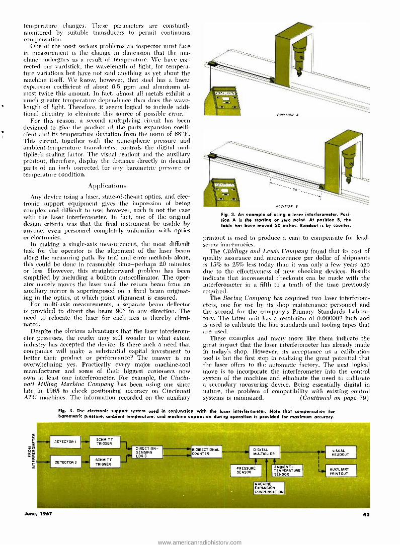
temperature changes. These parameters are constantly monitored by suitable transducers to permit continuous compensation.
One of the most serious problems an inspector must face in measurement is the change in dimension that the ma- chine undergoes as a result of temperature. We have cor- rected our yardstick, the wavelength of light, for tempera- ture variations but have not said anything as yet about the machine itself. We know, however, that steel has a linear expansion coefficient of about 6.5 ppm and aluminum al- most twice this amount. In fact, almost all metals exhibit a much greater temperature dependence than does the wave- length of light. Therefore, it seems logical to include addi- tional circuitry to eliminate this source of possible error.
For this reason, a second multiplying circuit has been designed to give the product of the parts expansion coeffi- cient and its temperature deviation from the norm of 68 °F. This circuit, together with the atmospheric pressure and ambient- temperature transducers, controls the digital mul- tiplier's scaling factor. The visual readout and the auxiliary printout, therefore, display the distance directly in decimal parts of an inch corrected for any barometric pressure or temperature condition.
Applications
Any device using a laser, state -of- the -art optics, and elec- tronic support equipment gives the impression of being complex and difficult to use; however, such is not the case with the laser interferometer. In fact, one of the original design criteria was that the final instrument be usable by anyone, even personnel completely unfamiliar with optics or electronics.
In making a single -axis measurement, the most difficult task for the operator is the alignment of the laser beam along the measuring path. By trial and error methods alone, this could be done in reasonable time -perhaps 20 minutes or less. However, this straightforward problem has been simplified by including a built -in autocollimator. The oper- ator merely moves the Iaser until the return beam from an auxiliary mirror is superimposed on a fixed beam originat- ing in the optics, at which point alignment is ensured.
For multi -axis measurements, a separate beam deflector is provided to divert the beam 90° in any direction. The need to relocate the laser for each axis is thereby elimi- nated.
Despite the obvious advantages that the laser interferom- eter possesses, the reader may still wonder to what extent industry has accepted the device. Is there such a need that companies will make a substantial capital investment to better their product or performance? The answer is an overwhelming yes. Practically every major machine -tool manufacturer and some of their biggest customers now own at least one interferometer. For example, the Cincin- nati Milling Machine Company has been using one since late in 1965 to check positioning accuracy on Cincinnati ATC machines. The information recorded on the auxiliary
rc w r w
f0 O IC w w w r z
Fig. 3. An example of using a laser interferometer. Posi- tion A is the starting or zero point. At position B, the table has been moved 50 inches. Readout is by counter.
printout is used to produce a cam to compensate for lead - screw inaccuracies.
The Giddings and Lewis Company found that its cost of quality assurance and maintenance per dollar of shipments is 15% to 25% less today than it was only a few years ago due to the effectiveness of new checking devices. Results indicate that incremental checkouts can be made with the interferometer in a fifth to a tenth of the time previously required.
The Boeing Company has acquired two laser interferom- eters, one for use by its shop maintenance personnel and the second for the company's Primary Standards Labora- tory. The latter unit has a resolution of 0.000002 inch and is used to calibrate the line standards and tooling tapes that are used.
These examples and many more like them indicate the great impact that the laser interferometer has already made in today's shop. However, its acceptance as a calibration tool is but the first step in realizing the great potential that the laser offers to the automatic factory. The next logical move is to incorporate the interferometer into the control system of the machine and eliminate the need to calibrate a secondary measuring device. Being essentially digital in nature, the problem of compatibility with existing control systems is minimized. (Continued on page 79)
Fig. 4. The electronic support system used in conjunction with the laser interferometer. Note that compensation for barometric pressure, ambient temperature, and machine expansion during operation is provided for maximum accuracy.
BIDIRECTIONAL COUNTER
DIGITAL MULTIPLIER
PRESSURE SENSOR
AMBIEN T - TEMPERATURE SENSOR
MACHINE EXPANSION COMPENSATION
VISUAL READOUT
AUXILIARY PRINTOUT
June, 1967 45
www.americanradiohistory.com

INPUT (FROM BALANCED MODULATOR)
L< SIDEBAND FILTER 464.5kHz
1.5 -7.0 pF T I F AMP
6BÁ6 5
T15 L
2.2k
1
I T2 J2 OUTPUT
( TO FREQUENCY 1 ' CONVERTER)
I/2W
L 1.5-7.0 1.5-7.0
pF pF
CI,C2- 1500pF 5' /.(MATCHED PAIR) * AUTHOR USED 2 PARALLELED .0003pF MICAS
J I , J2 - PHONO JACK LI, L2- HIGH=O "FERRITE ANTENNA COIL ( MILLER *6300)
TI -450- 475kHz, I.F. TRANSFORMER(MILLER *112 -CI) XTAL I, XTAL 2- 465.277kHz, FT -241 -A CRYSTAL, CHANNEL 335, MATCHED PAIR ( TEXAS CRYSTALS) T2- " " ( " *112 -C4) XTAL3, XTAL 4- 462.963 kHz, " " " " " 50
68 112W
33k 1/2W
Ik I/2W
6.3V 195V
L .01
Fig. 1. Filter consists of two cascaded half -lattice crystal -filter sections with low- impedance input and high- impedance output.
Ferrite Coil and Crystal
Sideband Filter By RICHARD A. GENAILLE, K4ZGM
Using readily available ferrite antenna coils in place of the usual i.f. transformers, this filter can be employed as the starting point for the construction of an SSB barn, transmitter.
OST of the single -sideband transmitters in use to- day employ either the filter method or thé phase - shift method of sideband selection. The heart of a
t-ansnuitter making use of the former method is, of course, t le filter which accomplishes frequency discrimination in t 1e low, medium, or high -frequency ranges. Among the var- i its filters which have been widely used are mechanical filters, filters made up of precision high -"Q" toroidal circuits, and quartz crystal filters. This article describes an easily con- structed, medium -frequency crystal filter using readily avail- able quartz crystals in unique combination with ordinary ferrite coils and which, in addition, contains a stage of am- plification as an integral part of the filter unit. The filter can be used as the starting point for that sideband transmit- ter that you have always wanted to build.
The ferrite coil and crystal sideband filter is shown sche- matically in Fig. 1. The basic sideband filter circuitry con- sists of two cascaded half -lattice crystal -filter sections with input and output circuitry arranged for a low -impedance input to the filter proper and a high -impedance output from the filter to the i.f. amplifier stage. The input impedance of the filter was designed to accommodate the output of a low - impedance balanced modulator. A simple, high -"Q" ferrite antenna coil is used in a tuned circuit to provide the transi- tion from low -impedance input to the high impedance of the first half -lattice crystal section.
Ordinarily, one would refer to the crystals used as "sur- plus" crystals; however, the tremendous popularity which medium -frequency crystals have enjoyed over the years of use in crystal filters such as the one being described, has resulted in suppliers dropping. -the term "surplus" from their advertisements and making available matched pairs of crys- tals at a nominal cost.
The exact frequencies or channels shown in Fig. 1 are not rigid but the limit of the lower frequency crystals used should not be below 450 kHz and the higher frequency crys- tals should not be above 47:5 kHz. The frequency separa-
46
tion between the crystal pairs determines the bandwidth of the filter and most lattice filters constructed from the type crystals and the standard components specified will have a bandwidth of about one and one- fourth times the frequency difference between the crystal frequencies. A frequency sep- aration of approximately 2.3 kHz is used in this filter which provides a bandwidth of near 2.9 kHz for reasonable voice quality.
The crystal trimmer capacitors provide a means of im- proving the shape factor of the filter and should be of good quality. The ones used in the author's filter were Centralab ceramic- diele<trie triuuners #822 -EZ. The i.f. transform-
Fig. 2. Capacitor and coil adjustments are shown in this fop view. Trimmer for crystal 1 is identified as X 1 , and so on.
ELECTRONICS WORLD
www.americanradiohistory.com

ers as well as the inexpensive ferrite coils were selected to minimize filter losses.
Capacitors Cl and C2 need not be exactly 1500 pF but should be matched as closely as possible. The author bought a half -dozen 5% tolerance capacitors of good quality and, using a "Q" meter, was able to select a pair that was almost perfectly matched. A simple voltage divider test circuit may be used to establish a match of the two capacitors. The ca- pacitors to be checked can be connected in series and across a source of medium -frequency r.f. signal. The voltage mea- sured across each capacitor with a v.t.v.m. should be the same if the capacitance values are alike.
The i.f. amplifier stage is a basic circuit which is used to provide the necessary gain to drive a following converter circuit and to facilitate the testing and alignment of the fil- ter as a separate unit from the rest of the transmitter in which the filter may be used. The filter should be aligned using a low value of input signal to prevent overdriving and subsequent errors in alignment. The combination of low input signal and filter insertion loss results in difficulty in obtaining a suitable output level for driving the average scope or v.t.v.m. The integral i.f. amplifier circuit provides the needed gain and makes possible the testing of the filter as a complete separate sub -unit from the transmitter proper.
Construction Details Construction of the filter is not difficult; however, con-
siderable effort was expended in shielding the various filter components to insure that the input signal would pass through and not around the filter. The filter components are housed in a 7" X 5" X 3" chassis box as shown in the pho- tographs of Figs. 2 and 3. Fig. 3 shows the placement of the various components. The shields used for the ferrite coils, the small shield cans for the input and output jacks, the shield partitions separating the filter input and output sections, and the shield partition separating the filter proper from the i.f. amplifier stage are also shown in Fig. 3. Fig. 4 is a view of the filter with the shield cans removed as well as the lids of the input and output jack shield cans. Dis- carded 35 -mm film cans are used as shield cans for the in- put and output jacks. The removable covers provide excel- lent access for the mounting as well as for the wiring to the jacks.
The small crystal trimmer capacitors are mounted on phenolic strips and are used as a means of support for the crystals by soldering the crystal holder pins directly to the trimmer capacitor leads. This method of supporting the crystals is shown in Fig. 5. It would be wise to use a heat sink of some sort on the crystal holder pins to avoid dam- age to the crystals from excessive heat if the builder uses this system of mounting, however. Other satisfactory means of supporting the crystals may be used by the imaginative con- structor rather than the means described.
Alignment Techniques The filter can be aligned by using a signal generator and
a v.t.v.m. in the point -by -point system of alignment but this method can be very time consuming. The use of an i.f. sweep generator sweeping the 425 to 475 kHz range and an oscilloscope is recommended and is the method used by the author for aligning the filter. For those who may wish to make an interim alignment with an r.f. signal generator and a v.t.v.m. the following procedure will produce passable re- sults.
As mentioned previously, the inclusion of an i.f. amplifier as an integral part of the filter makes it unnecessary to use a high input voltage to the filter and risk damaging the crystals. In starting the filter alignment all crystal trimmers should be adjusted for minimum capacitance. The output of an accurately calibrated r.f. signal generator should be connected to the input jack on the filter with the output jack
June, 1967
OUTPUT JACK INPUT JACK XTAL 4 T2 SHIELD CAN SHIELD CAN
XTAL 2 C2 CI XTAL I
Fig. 3. Inside view showing parts placement and the internal shields. Coil and jack shield cans are in place in this view.
Fig. 4. Inside view with the shields and /or covers removed.
Fig. 5. Method of mounting crystals on the crystal trimmers.
connecte_ to the r.f. probe of a vacuum -tube voltmeter. Ferrite coils L1 and L2 and i.f. transformers Ti and T2
should be adjusted for maximum output at the center of the filter passband. The center of the passband, as shown in the characteristic curve for this filter in Fig. 6 approximately 464.5 kHz. With the signal generator set to 462.5 kHz, the trimmer capacitors associated with the lower frequency crystals (X3, X4) should be adjusted for a sharp null on the v.t.v.m. With the signal generator set at 466 kHz, adjust the trimmer capacitors associated with the higher frequency crystals (X1, X2) for a sharp 111111 also. These adjustments, as previously mentioned, will pro- (Continued on page 80)
47
www.americanradiohistory.com

Common -Sense Design of
TRANSISTOR AMPLIFIERS By DONALD L. CARLSON
Manager of Engineering Services, Hewlett- Packard (Loveland Div.)
Straightforward method of calculating the necessary circuit components for a stage of transistor amplification. Ohm's Gate /glus sonie simple formulas are all that are required.
IT is not too difficult to find the information needed to design a tube -type amplifier. lllost tube manuals include characteristic curves and other pertinent data, and with
a little knowledge of plotting load lines and a few other calculations, the builder may come up with a suitable design. However, working with transistors is a different mat- ter. For the most part, the average technician does not have access to the manufacturer's information and, if he did, would probably throw his hands up in disgust by the time he waded through all the calculations necessary to design a single -stage amplifier. Most manufacturers specify their transistor devices using hybrid parameters. These parameters are not very easily grasped until some of the more basic principles are understood.
The following is a straightforward method -a common- sense approach, using Ohm's Law to calculate the necessary circuit components for a complete amplifier. Although there are hundreds of types of transistors, for simplicity, we will discuss only one type in this article.
Some of the available types fall into the following clas- sifications: small -signal amplifiers, switching transistors, high- frequency transistors, and power transistors, to name a few. There are also voltage ratings, power and current ratings, and leakage currents to consider in selecting the transistor to handle a specific job.
The Transistor Specifications As an example, let's start with a one -stage amplifier using
a 2N2712 and calculate all the necessary circuit com- ponents. This is an n -p -n silicon transistor capable of per- forming all functions in an A \I radio. This means that not only will it work well at audio frequencies, but it will also amplify well at radio frequencies. Although it is very in- expensive, it does have some very good specifications. Some of the more important specs will be discussed.
VUr, is 18 volts: This is the maximum voltage allowable from collector to emitter and, for all practical purposes, should be the maximum supply voltage since the full volt- age would be applied between collector and emitter any time that the transistor is in cut -off condition.
VEIJ is 5 volts: This is the maximum voltage from emit- ter to base with the collector open.
1,, is 100 mA: This is the maximum saturation current or the collector current when the transistor is saturated.
PT is 200 m \V: This is the maximum power dissipation. 1,,,; is 1 p.A maximum: This is the collector -to -base leak-
age current with the emitter open, and with V,.,; = 18 V. II,.!, is 75 minimum, 225 maximum: This is also known as
heat or d.c. current gain. The "F" is for forward current transfer ratio, and the "E" indicates a common- emitter con - figuration.
The static characteristic curve for a 2N2712 is shown in Fig. 1. This type of curve can be plotted by hand on
graph paper. All that is needed is a variable power supply (labeled B1 in Fig. 2A), a milliammeter to monitor the collector current, and a voltmeter to monitor the collector voltage, as shown. B2 furnishes the base current and R. may be a number of fixed resistors which will apply the required base current to the transistor. For instance, if B2 = 1.5 volts, then R,, would equal 150,000 ohms for 10 -pA base drive. As the variable power supply is increased in voltage, the current is monitored at two or three collector voltages and points then marked for these readings. A line is then drawn connecting all points.
This is the same type of curve that is published in a tube manual for electron tubes. The only difference is that the grid of a tube is biased with the voltage where the transistor, because of its forward- biased emitter -base junc- tion, is a current- driven device.
Construction of Load Line Let's construct a load line and get as much information
as possible from this set of curves. As a start, if we draw a 3000 -ohm load line, that is, from lc = 5 mA (15/3000 = .005) to V,. = 15 volts, we have the basis for a start of an amplifier. Now to get all the information from the curves -note that point "O" which is the intersection of the 30 -p.A base- current curve and the 3000 -ohm load line is directly above V,. = 7 volts. This means that for this value of base current and the 3000 -ohm load, we could expect +7 volts at the collector (Fig. 2A) .
The curve also tells us what the current gain or h,,.,. is. This is the ratio of the collector current change divided by the base current change. We will call it beta. From the dotted lines "A" to I, = 3.7 mA and "13" to I,. = 1.8 mA, a difference in collector current of 3.7 - 1.8 = 1.9 mA is caused by a change of 40 - 20 p.A = 20 p.A in base current. Then 1.9 mA is divided by 20 pA = 95, for a current gain of 95.
It should be understood that point "O" is the quiescent operating condition and that if an input signal, let's say a sine wave, were applied to the base of the transistor of such amplitude that it caused, on the positive -going signal, the base current to increase to 40 µA, and on the negative excursion of the signal, to decrease the base current to 20 1. A, the collector voltage would then swing from 4.2 volts to 9.8 volts. This would be a useful output signal (E ) to drive a following stage or transducer of some type.
If we were constructing more than one stage in an am- plifier, it might be well to use a larger value resistor in an early stage to get more voltage gain. To see how this works out, let's check E for the 3000 -ohm load and then draw a 6000 -ohm load line and see the difference. From point "A to = 4.2 volts and point "B" to Ve = 9.8 volts there is a difference of 5.6 volts or E = 5.6 volts. This is a peak - to -peak voltage. From point "C" to Ve = 0.6 volt and
48 ELECTRONICS WORLD
www.americanradiohistory.com

point "D" = 10.5 volts, we have a difference of 9.9 volts, considerably more than was obtainable with the 3000 -ohm load.
An even larger value could be used and still maintain a fairly linear output. On the curves of Fig. 1, lay a straight- edge from le = 2 mA to Vt, = 15 volts. The intersection at the 1 -mA value would equal about 13 µA base current. This would give maximum voltage swing from saturation, which would be 2 mA and 0 volts, to cut -off, which would be 0 mA and 15 volts.
Another thing to keep in mind when working with low - level amplifiers is that it is a good idea to keep the collector voltage and current low. This helps maintain a low noise - to- signal ratio.
To add a little more detail to the circuit, let's draw the amplifier using the 6000 -ohm load (see Fig. 2C). At oper- ating point "0.,", we have 20 -µA base drive. We could complete the amplifier, except for d.c. bias stability, by con- necting a 750,000 -ohm resistor between the +15 -volt sup- ply and the base to bias the transistor. It is apparent that the base resistor R1 was calculated using Ohm's Law [R = E/I = 15/(2 x 10 -') = 750 kohms]. Also note that as long as the input swing is not too great, this amplifier will work in class -A condition; however, the operating point on the 3000 -ohm load line is a better choice, only because the operating point is such that at a quiescent condition approximately one -half of the voltage is dropped across the transistor and the balance across the load resistor.
Fig. 3 shows a characteristic curve with a 3000 -ohm load line plotted. Input and output current and output voltage waveforms are also shown. The input voltage waveform would be a function of the voltage across the input im- pedance of the transistor amplifier.
Fig. 4 shows a characteristic curve with the maximum 200 -mW curve drawn in. Any load line drawn tangent to the constant power dissipation line will insure maximum power gain of the transistor. The theoretical maximum power gain is the maximum current and voltage gain. How- ever, the condition for maximum current gain is RL - 0 and the condition for maximum voltage is /IL = Do.
Since these conditions are in opposition, the problem of finding the maximum power gain involves matching the input and output resistances of the transistor. The maximum power gain is obtained when the internal resistance of the signal generator is equal to the input resistance of the tran- sistor, and the load resistance is equal to the output re- sistance of the transistor. When these conditions are simultaneously satisfied, the transistor is image- impedance matched. In practice, it is possible to use transformer cou- pling and achieve matched impedance conditions, although the majority of designs use RC -type circuits where the load resistance and d.c. -bias network will tend to modify the gain of the transistor amplifier whether it be on a current, power, or voltage basis.
Distortion and its Causes An oscilloscope is a good tool to use when working with
amplifiers. If too large an input signal is applied to the amplifier, it may cause clipping which can be observed on the scope. If both the negative and positive portions of the output sine wave are clipped, this simply means the amplifier is overdriven. If, on the other hand, only one -half of the sine wave is clipped, this indicates that either the load or bias resistors are the wrong value. Two extremes, one being the selection of too low a value of collector volt- age and the other too high are discussed in the following examples.
Referring to the characteristic curve in Fig. 1 and using operating point "C" on the 6000 -ohm load line, if a sine - wave signal is applied to the base of the transistor, it is apparent that as the input signal goes positive, the collector voltage will approach zero and any further increase in sig-
June, 1967
1.1 IC all vvnnb vuy... .., ... , -- ---_
June, 1967
ú
2
7OyA
GOO
PA real
SOPA '_ RASE CURR NT
4054 - IN
!:IT! =- .
t 1= stL4oLYy 1
I ,
I
I I 1 I.
I I I I i
ww
0 z 4 6 7 e 10 z COLLECTOR VOLTAGE (Vc) -VOLTS
Fig. 1. Characteristic curves for the type 2N12712 transistor.
mA METER
E
(A)
lope
VcC=+15V
3kn
14 15
(B) (C)
Fig. 2. (A) Setup for obtaining characteristic curves. (B) Op- eration with 3000 -ohm load and ICI with a 6000 -ohm load.
OUTPUT CURRENT
10
s
e
< E
6 u H
á
4
3
2
/ IN' UT Ahs. CU RENT -- / 1o
limmum rwai- CrIMMA111101111 Iiú mi ill
( \® AIN I ' 10- 2 4)
OUTPUT VOLTAGE
6 8 ; 10 12 14 16
VC -VOLTS le 20
Fig. 3. Use of load line to show input and output currents, voltage.
Fig. 4. Curved line indicates the maximum power dissipation of 200 mW along its entire length. The straight line is a typical load line indicating transistor operation with a maximum power gain.
loo
90
80
70
60
Q 50 H
40
30
20
10
ONSTIINT PCIWER r ISSIPATION LINE W=2 X E E="200mW - 1- PE TAP `, gi-&. Mi-
CI - -- / - 0 2 4 6 8 10 12
Vc -VOLTS 14 16 18 20
49
55
www.americanradiohistory.com
"He's a good worker.
I'd promote him right now if he had more education in
electronics:'
ELECTRONICS WORLD
www.americanradiohistory.com

June, 1967
Could they be talking about you?
You'll miss a lot of opportunities if you try to get along in the electronics industry without an advanced education. Many doors will be closed to you, and no amount of hard work will open them.
But you can build a rewarding career if you supplement your experience with specialized knowledge of one of the key areas of electronics. As a specialist, you will enjoy security, excellent pay, and the kind of future you want for yourself and your family.
Going back to school isn't easy for a man with a full -time job and family obligations. But CREI Home Study Programs make it pos- sible for you to get the additional education you need without attending classes. You study at home, at your own pace, on your own schedule. You study with the assurance that what you learn can be applied to the job immediately.
CREI Programs coverall important areas of electronics including communications, servo -mechanisms, even spacecraft tracking and control. You're sure to find a program that fits your career objectives.
You're eligible for a CREI Program if you work in electronics and have a high school education. Our FREE book gives complete information. Airmail postpaid card for your copy. If card is de- tached, use coupon below or write: CREI, Dept. 1128 E, 3224
Sixteenth Street, N.W., Washington, D.C. 20010.
Founded 1927
CREI Accredited Member
of the National Home Study Council
r The Capitol Radio Engineering Institute Dept. 1128 E, 3224 Sixteenth Street, N.W., Washington, D.C. 20010
Please send me FREE book describing CREI Programs. I am em- ployed in electronics and have a high school education.
NAME AGE
ADDRESS
CITY STATE ZIP CODE
EMPLOYED BY
TYPE OF PRESENT WORK GI BILL
I am interested in Electronic Engineering Technology Space Electronics Nuclear Engineering Technology
Industrial Electronics for Automation Computer Systems Technology
J
APPROVED FOR VETERANS ADMINISTRATION TRAINING
59
www.americanradiohistory.com

Build your own
AUTO ANALYZER -and SAVE!
It's FUN! It's EASY! knight -kite
FROM
ALLIED RADIO Headquarters for Everything in Electronics
SetEngineldle -Auto Trans. Shift Points
CHECK:
Distributor wear
Dwell angle Voltage regulator Condensers Point surfaces Coil resistance Ground circuits Alternator diodes
Engine timing Spark output and much more!
Save double on this famous Knight -Kit Auto Analyzer. Build it yourself and save factory assembly costs. Then use it for tuneups and trouble- shooting to hold down car upkeep.
Write for special introductory offer.
No Money Down $5 Monthly
ALLIED RAD IO Dept. IF, P.O. Box 4398, Chicago, III. 60680
CIRCLE NO. 125 ON READER SERVICE CARD
The Heart of your Radio is Its
INSIST ON
OCC*1
EXAS vsTAlS
*Controlled Quality Crystals available only from Texas Crystals dealers. Ex- tensive precision testing throughout manufacture enables Texas Crystals to unconditionally guarantee their fre- quency control crystals. Use of Texas Crystals in space program and by other governmental agencies is evi- dence of the quality you can count on.
If your dealer can't supply your needs, send his name with your
request for catalog to our plant nearest you.
TEXAS CRYSTALS -
Division of Whitehall Electronics Corp.
1000 Crystal Drive 4117 W. Jefferson Blvd. Fort Myers, Fla. 33901 Los Angeles, Calif. 90016 Phone: 813 -936 -2109 Phone: 213-731-2258
CIRCLE NO. 196 ON READER SERVICE CARD 60 ELECTRONICS WORLD
RADIO
TV NEWS
THE classic theory that the eye sees color because of red, green, and
blue cones in the retina has been chal- lenged by George Biernson of the Syl- vania Applied Research Lab. At the last meeting of the IEEE, Mr. Biernson dis- cussed the probability that the eye may perceive color by detecting rhythmic optical modes or patterns in the cones.
Mr. Biernson likened these optical patterns to vibrations of a drum. "When a drum is struck, complicated vibration patterns are excited over the druni head. Similarly, colors generate patterns of light energy over the cone, the patterns varying with the wavelength of the light.
"Although the retina of the eye super- ficially may appear similar to the photo- sensitive surface of a three -color TV camera, the two are radically different from a feedback point of view. The photosensitive surface of a TV camera is a static device with fixed characteristics, whereas the retina of the eye is a dy- namic device employing complex feed- back control processes," he explained.
Mr. Biernson went on, "The eye, which can discriminate among 10 mil- lion colors, is superior in color detection to TV or photography, which can dis- tinguish only a few hundred colors. The greater color fidelity of the eye may be better explained by optical modes or patterns than by the three -cone theory."
The chief difficulty in resolving the mystery of color, according to Mr. Biern- son, is a mistaken conviction that the three -color calculations of colorimetry characterize human vision. "What is not generally understood is that colorim- etry is merely a collection of standards indirectly related to psychological real- ity. In fact, the standards were derived by extensive averaging of very crude experimental data."
Digital Policeman Through a technique known as "dig-
ital overlay ", direct digital communica- tions between cruising police patrol cars and a central computer for on- the -spot checking of police records may soon be used by the nation's police in its fight against the rising crime rate.
Recent tests by both police and G -E engineers indicate that small -size, two-
way Teletype machines installed in squad cars permit faster, more accurate "talk" between a central computer and the police officers. Both voice and Tele- type messages can be sent simultaneous- ly over the same voice channel with no mutual interference between the two channels.
Tests show that this new method of communications produces clear Teletype copy even when conditions are such that voice communications are particularly bad.
Tape Recorder Help If you Own one of the expensive
($700 to $1000) Japanese tape record- ers having the names of Freeman, Neat, Frontier, Camena Voice, Stereocraft, or Vansonic, you should know that the company (Tsbusa Sanyo) is no longer in business. For parts and other infor- mation, contact Mr. Emory R. Howell, 3917 N. 31st St., Waco, Texas 76708.
FM Spurts In the past five years, the number of
FM stations in the U.S. has increased by more than 70%, from 889 stations in 1961 to 1521 stations in 1966. Also, the number of stations broadcasting FM- stereo has skyrocketed 780%, from 50 to more than 440 stations at present.
Along with this expansion in broad- casting, sales of FM radios have zoomed more than 500 %, with last year's total reaching a record high of nearly 10 mil- lion units.
One major contribution is the fact that the FCC now prohibits duplication of more than 50`- of programming heard on commonly owned AM -FM facilities in the larger cities.
Laser Drill If you have ever had to drill fine holes
using a #54 drill bit (0.0055 "), you will appreciate the new instrument de- veloped at RCA Aerospace Systems. In this new look in drills, a ruby laser is aimed through a series of special optical lenses; when the button is pressed, lo and behold, the laser drills perfect- ly round holes only 0.00048" in diam- eter through a human hair of 0.0042" diameter.
www.americanradiohistory.com

Measuring Tracking Ability Continued from p(!gc 28)
At present, we know of no suitable tone burst record, but expect that it is only a matter of time until one is available so that this method can be thoroughly investigated.
Subjective Evaluation The ultimate aim in making, tracking -ability measure-
ments is to correlate these measurements with subjective listening. We have made an extensive evaluation of phono- graph cartridges from the standpoint of tracking ability, primarily through use of the variable-speed turntable tech - nique. Cartridges so measured have been compared using a record entitled "An Audio Obstacle Course" designed spe- cifically for subjective evaluation of tracking ability. (Avail- able from Shure Brolhcrs, Inc., 222 Ilartrev Ave., Evanston, Illinois 60204 at 8:3.95 each.) This record contains a series of bands using different musical instruments. Each band is subdivided into four sub -bands containing the identical musical selection with each successive band cut at a level 4 -dli higher than the previous one. In playing this record, one notes the modulation level for each instrument at which the cartridge ceases to track. A chart like that shown ill Fig. 7 can then be obtained. This provides a subjective evaluation of the cartridge tracking ability.
We have found good correlation between the tracking - ability measurements made on the variable -speed turntable and those made with "An Audio Obstacle Course". For example, cartridges which have or tracking ability at low frequencies are found to be very poor on the band containing a bass drum beat. Cartridges which track poorly at high frequencies are also found to be poor on such instruments as orchestral bells and cymbals. After many such comparisons, we have found that by making an analysis of the tracking - ability measurements, we can predict with good accuracy the subjective characteristics which will be obtained with the record.
Conclusion The tracking ability of a phono cartridge is analogous to
clipping level in amplifiers. Lu both cases large peak input signals which drive the device into saturation cause intoler- able distortion.
While there are many characteristics of a phonograph cartridge that contribute to the quality of reproduction. track- ing ability is one of the major characteristics xvhich affect the ultimate sound. Measurement of this characteristic is an extremely important factor in any evaluation. For this reason we believe that a means for making such a measure- ment should be standardized and that tracking ability should be among the specifications listed for phono cartridges. A
Fig. 7. Chart of tracking ability using test record described.
MONO LEFT CHANNEL RIGHI CHANNEL
LEVEL 08 D 6 C BD 0 P A H 0 P A H
I
2
3
4
e e
e
TRA
8
CKS
e
9 e
e e
e 9
MIST RACKS
OB- ORCHESTRAL 3ELLS DAC -DRUM S CYMBALS
BD -BASS DRUM
0- ELECTRONIC ORGAN
P -PIANO A - ACCORDION
H- HARPSICHORD
9- INDICATES CARTRIDGE TRACKS
June, 1967
FREQUENCY RANGE
HIGH
HIGH
LOW
MID
MID
MID
HIGH
UALITY from PEARCE-SIMPSON
...THE LEADER *
30 WATT AM 2 -WAY BUSINESS BAND RADIO with remote head* 12 Volt Model $329.90
Frequencies FCC allocated for business /industrial use.
' ''Can be dash mounted as a complete radio or the removable 21/2 Ib. remote control head can be ins`alled independently with its own mount- ing cradle Solid state power supply and re- ceiver for low power drain (.6 amps.)
C3lJ/.III/1I =O3 CB TWO -WAY RADIO $269.90
23 CHANNELS- features exclusive HETROSYNC circuitry. Two signals are combined instead of the usual 3 providing outstanding stability and maximum protection against spurious signals.
Dual conversion superhet receiver with low noise Nuvistor front end RF gain control, tone control and noise limiter switch Illuminated "S" meter Transistorized universal (AC /DC) power supply.
WORLD'S LARGEST PRODUCER OF MARINE RADIOTELEPHONES
Please send me full details and specifications on the: J "IBC 301" ._ CB "GUARDIAN" Name
Address
City
State.. Zip
PEARCE- SIMPSON, INC. P.O. Box 800 -Biscayne Annex Miami, Fla. 33152
CIRCLE NO. 102 ON READER SERVICE CARD 61
www.americanradiohistory.com
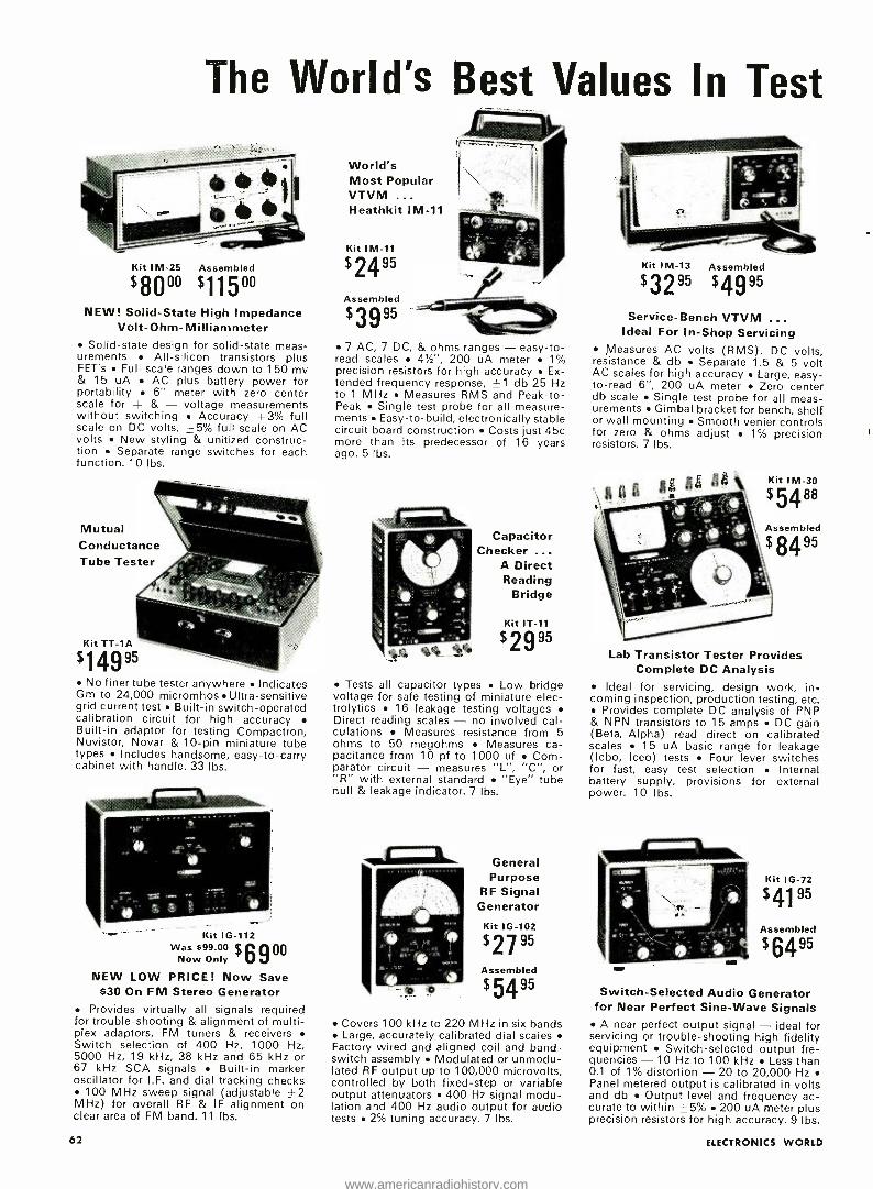
The World's Best Values In Test
Kit IM -25 Assembled
$8000 $115°° NEW! Solid -State High Impedance
Volt- Ohm -Milliammeter Solid -state design for solid -state meas-
urements All- silicon transistors plus FET's Full scale ranges down to 150 my & 15 uA AC plus battery power for portability 6" meter with zero center scale for + & - voltage measurements without switching Accuracy ±3% full scale on DC volts, _ 5% full scale on AC volts New styling & unitized construc- tion Separate range switches for each function. 10 lbs.
Mutual Conductance Tube Tester
No finer tube tester anywhere Indicates Gm to 24,000 micromhos Ultra-sensitive grid current test Built -in switch- operated calibration circuit for high accuracy Built -in adaptor for testing Compactron, Nuvistor, Novar & 10 -pin miniature tube types Includes handsome, easy -to -carry cabinet with handle. 33 lbs.
Kit IG -112 Was $99.00 $A900
Now Only
NEW LOW PRICE! Now Save $30 On FM Stereo Generator
Provides virtually all signals required for trouble- shooting & alignment of multi- plex adaptors, FM tuners & receivers Switch selection of 400 Hz, 1000 Hz, 5000 Hz, 19 kHz, 38 kHz and 65 kHz or 67 kHz SCA signals Built -in marker oscillator for I.F. and dial tracking checks
100 MHz sweep signal (adjustable ±2 MHz) for overall RF & IF alignment on clear area of FM band. 11 lbs.
62
World's Most Popular VTVM ... Heathkit IM -11
Kit IM -11
$24" Assembled
$39x5
7 AC, 7 DC, & ohms ranges - easy -to- read scales 41/2", 200 uA meter 1% precision resistors for high accuracy Ex- tended frequency response, ± 1 db 25 Hz to 1 MHz Measures RMS and Peak -to- Peak Single test probe for all measure- ments Easy -to- build, electronically stable circuit board construction Costs just 45c more than its predecessor of 16 years ago. 5 lbs.
Capacitor Checker ...
A Direct Reading
Bridge
Kit IT -11
$2995
Tests all capacitor types Low bridge voltage for safe testing of miniature elec- trolytics 16 leakage testing voltages Direct reading scales - no involved cal- culations Measures resistance from 5 ohms to 50 megohms Measures ca- pacitance from 10 pf to 1000 of Com- parator circuit - measures "L ", "C ", or "R" with external standard "Eye" tube null & leakage indicator. 7 lbs.
i
General Purpose
RF Signal Generator
Kit IG -102
$2795
Assembled
$5495
Covers 100 kHz to 220 MHz in six bands Large, accurately calibrated dial scales
Factory wired and aligned coil and band - switch assembly Modulated or unmodu- lated RF output up to 100,000 microvolts, controlled by both fixed -step or variable output attenuators 400 Hz signal modu- lation and 400 Hz audio output for audio tests 2% tuning accuracy. 7 lbs.
Kit IM -13 Assembled
$3295 $4995 Service -Bench VTVM
Ideal For In -Shop Servicing Measures AC volts (RMS), DC volts,
resistance & db Separate 1.5 & 5 volt AC scales for high accuracy Large, easy - to -read 6 ", 200 uA meter Zero center db scale Single test probe for all meas- urements Gimbal bracket for bench, shelf or wall mounting Smooth venier controls for zero & ohms adjust 1% precision resistors. 7 lbs.
Kit IM -30
$5488
Assembled
$8495
Lab Transistor Tester Provides Complete DC Analysis
Ideal for servicing, design work, in- coming inspection, production testing, etc.
Provides complete DC analysis of PNP & NPN transistors to 15 amps DC gain (Beta, Alpha) read direct on calibrated scales 15 uA basic range for leakage (lcbo, Iceo) tests Four lever switches for fast, easy test selection Internal battery supply, provisions for external power. 10 lbs.
Kit IG -72
$41" Assembled
$64"
Switch- Selected Audio Generator for Near Perfect Sine -Wave Signals A near perfect output signal - ideal for
servicing or trouble- shooting high fidelity equipment Switch -selected output fre- quencies - 10 Hz to 100 kHz Less than 0.1 of 1% distortion - 20 to 20,000 Hz Panel metered output is calibrated in volts and db Output level and frequency ac- curate to within ±5% 200 uA meter plus precision resistors for high accuracy. 9 lbs.
ELECTRONICS WORLD
www.americanradiohistory.com
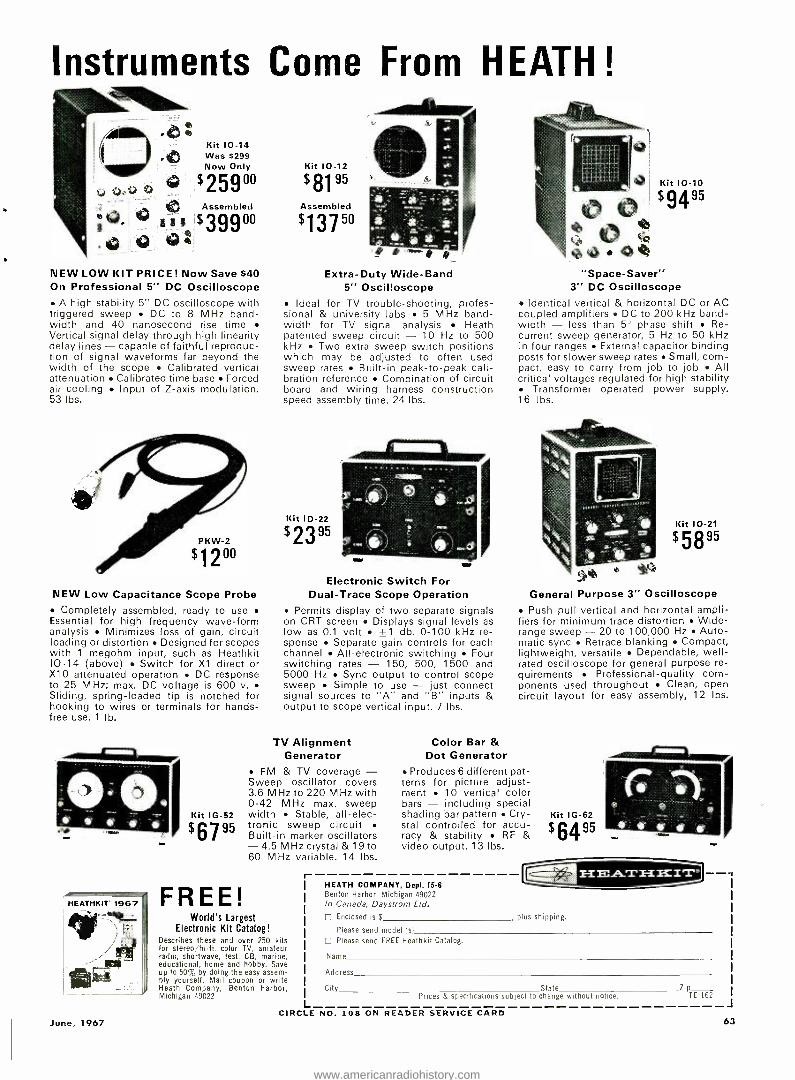
Instruments Come From HEATH! 44141._
Kit 10 -14 Was $299 Now Only
$25900
41
Assembled ° g $39900 t10 412
NEW LOW KIT PRICE! Now Save $40 On Professional 5" DC Oscilloscope
A high stability 5" DC oscilloscope with triggered sweep DC to 8 MHz band- width and 40 nanosecond rise time Vertical signal delay through high linearity delay lines - capable of faithful reproduc- tion of signal waveforms far beyond the width of the scope Calibrated vertical attenuation Calibrated time base Forced air cooling Input of Z -axis modulation. 53 lbs.
NEW Low Capacitance Scope Probe Completely assembled, ready to use
Essential for high frequency wave -form analysis Minimizes loss of gain, circuit loading or distortion Designed for scopes with 1 megohm input, such as Heathkit 10 -14 (above) Switch for X1 direct or X10 attenuated operation DC response to 25 MHz; max. DC voltage is 600 v. Sliding, spring -loaded tip is notched for hooking to wires or terminals for hands - free use. 1 Ib.
_IV d`. ,>401
HEATHKIT 1967
Kit IG -52
$6795
Kit 10 -12
$8195
Assembled
$13750 *,P
Extra -Duty Wide -Band 5" Oscilloscope
Ideal for TV trouble- shooting, profes- sional & university labs 5 MHz band- width for TV signal analysis Heath patented sweep circuit - 10 Hz to 500 kHz Two extra sweep switch positions which may be adjusted to often used sweep rates Built -in peak -to -peak cali- bration reference Combination of circuit board and wiring harness construction speed assembly time. 24 lbs.
Kit ID-22
$23" i Electronic Switch For
Dual -Trace Scope Operation Permits display of two separate signals
on CRT screen Displays signal levels as low as 0.1 volt ±1 db, 0 -100 kHz re- sponse Separate gain controls for each channel All- electronic switching Four switching rates - 150, 500, 1500 and 5000 Hz Sync output to control scope sweep Simple to use - just connect signal sources to , "A" and "B" inputs & output to scope vertical input. 7 lbs.
TV Alignment G enerator
FM & TV coverage - Sweep oscillator covers 3.6 MHz to 220 MHz with 0 -42 MHz max. sweep width Stable, all -elec- tronic sweep circuit Built -in marker oscillators -4.5 MHz crystal & 19 to 60 MHz variable. 14 lbs.
"Space- Saver" 3" DC Oscilloscope
Identical vertical & horizontal DC or AC coupled amplifiers DC to 200 kHz band- width - less than 5° phase shift Re- current sweep generator, 5 Hz to 50 kHz in four ranges External capacitor binding posts for slower sweep rates Small, com- pact, easy to carry from job to job All critical voltages regulated for high stability
Transformer operated power supply. 16 lbs.
Kit 10 -21
$58"
General Purpose 3" Oscilloscope Push -pull vertical and horizontal ampli-
fiers for minimum trace distortion Wide - range sweep - 20 to 100,000 Hz Auto- matic sync Retrace blanking Compact, lightweight, versatile Dependable, well - rated oscilloscope for general purpose re- quirements Professional -quality corn - ponents used throughout Clean, open circuit layout for easy assembly, 12 lbs.
Color Bar & r Dot Generator
Produces 6 different pat- terns for picture adjust- ment 10 vertical color bars - including special e shading bar pattern Cry- Kit 1G -62 stal controlled for accu- $6A 95 racy & stability RF & `F video output. 13 lbs.
Largest Kit Catalog! and over 250 kits color TV, amateur test, CB, marine, and hobby. Save the easy assem-
coupon or write Benton Harbor,
1-
L
HEATH COMPANY, Benton Harbor, Michigan In Canada, Daystrom
Enclosed is $
Dept. 15 -6 49022
Ltd.
plus shipping.
Please send model
Please send FREE
Name
(s)
Heath kit Catalog.
Address
City State Zip Prices S specifications subject to change without notice. TE -162
J
FREE! ``k._ World's
Electronic Describes these for stereo /hi -fi, radio, shortwave, educational, home up to 50% by doing bly yourself. Mail Heath Company, Michigan 49022
CIRCLE NO. 108 ON READER SERVICE CARD June, 1967 63
www.americanradiohistory.com
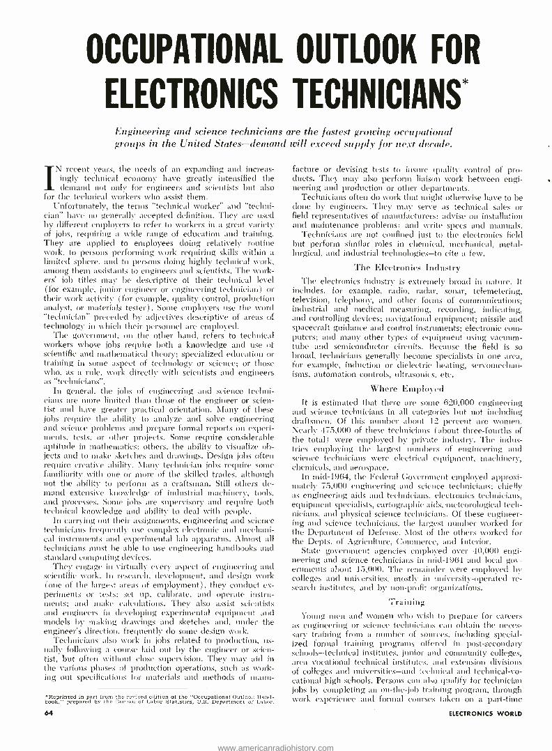
OCCUPATIONAL OUTLOOK FOR
ELECTRONICS TECHNICIANS` Engineering and science technicians are the fastest growing ueeajrntinnnl groups in the United States -demand will exceed supply for nevi decade.
V recent years, the needs of an expanding and increas- ingly technical economy have greatly intensified the demand not only for engineers and scientists but also
for the technical workers who assist them. Unfortunately, the terms "technical worker" and "techni-
cian" have no generally accepted definition. They are used by different employers to refer to workers in a great variety of jobs, requiring a wide range of education and training. They are applied to employees doing relatively routine work, to persons performing work requiring skills within a limited sphere, and to persons doing highly technical work, among them assistants to engineers and scientists. The work- ers' job titles may be descriptive of their technical level (for example, junior engineer or engineering technician) or their work activity ( for example, quality control, production analyst, or materials tester). Some employers use the word "technician" preceded by adjectives descriptive of areas of technology in which their personnel are employed.
The government, on the other hand, refers to technical workers whose jobs require both a knowledge and use of scientific and mathematical theory; specialized education or training in some aspect of technology or science; or those who, as a rule, work directly with scientists and engineers as "technicians ".
In general, the jobs of engineering and science techni- cians are more limited than those of the engineer or scien- tist and have greater practical orientation. Many of these jobs require the ability to analyze and solve engineering and science problems and prepare formal reports on experi- ments, tests, or other projects. Some require considerable aptitude in mathematics: others, the ability to visualize ob- jects and to make sketches and drawings. Design jobs often require creative ability. Many technician jobs require some familiarity with one or more of the skilled trades, although not the ability to perform as a craftsman. Still others de- mand extensive knowledge of industrial machinery, tools, and processes. Some jobs are supervisory and require both technical knowledge and ability to deal with people.
In carrying out their assignments, engineering and science technicians frequently use complex electronic and mechani- cal instruments and experimental lab apparatus. Almost all technicians angst be able to use engineering handbooks and standard computing devices.
They engage in virtually every aspect of engineering and scientific work. In research, development, and design work (one of the largest areas of employment), they conduct ex- periments or tests; set up, calibrate, and operate instru- ments; and make calculations. They also assist scientists and engineers in developing experimental equipment and models by making drawings and sketches and, under the engineer's direction, frequently do some design work.
Technicians also work in jobs related to production, us- ually following a course laid out by the engineer or scien- tist, but often without close supervision. They may aid in the various phases of production operations, such as work- ing out specifications for materials and methods of manu-
*Reprinted in part from the revised edition of the "Occupational Outlook Hand- book," prepared by the Bureau of Labor Statistics, U.S. Department of Labor.
facture or devising tests to insure quality control of pro- ducts. They may also perform liaison work between engi- neering and production or other departments.
Technicians often do work that might otherwise have to be done by engineers. They may serve as technical sales or field representatives of manufacturers; advise on installation and maintenance problems: and write specs and manuals.
Technicians are not confined just to the electronics field but perform similar roles in chemical, mechanical, metal- lurgical, and industrial technologies -to cite a few.
The Electronics Industry The electronics industry is extremely broad in nature. It
includes, for example, radio, radar, sonar, telemetering, television, telephony, and other forms of communications; industrial and medical measuring, recording, indicating, and controlling devices; navigational equipment; missile and spacecraft guidance and control instruments; electronic com- puters; and many other types of equipment using vacuum - tube and semiconductor circuits. Because the field is so broad, technicians generally become specialists in one area, for example, induction or dielectric heating, servomechan- isms, automation controls, ultrasonics, etc.
Where Employed It is estimated that there are some 620,000 engineering
and science technicians in all categories but not including draftsmen. Of this number about 12 percent are women. Nearly 475,000 of these technicians (about three -fourths of the total) were employed by private industry. The indus- tries employing the largest numbers of engineering and science technicians were electrical equipment, machinery, chemicals, and aerospace.
In mid -1964, the Federal Government employed approxi- mately 75,000 engineering and science technicians: chiefly as engineering aids and technicians, electronics technicians, equipment specialists, cartographic aids, -meteorological tech- nicians, and physical science technicians. Of these engineer- ing and science technicians, the largest number worked for the Department of Defense. Most of the others worked for the Depts. of Agriculture, Commerce, and Interior.
State government agencies employed over 40,000 engi- neering and science technicians in mid -1964 and local gov- ernments about 15,000. The remainder were employed by colleges and universities, mostly in university -operated re- search institutes, and by non -profit organizations.
Training Young amen and women who wish to prepare for careers
as engineering or science technicians can obtain the neces- sary training from a number of sources, including special- ized formal training programs offered in post -secondary schools -technical institutes, junior and community colleges, area vocational technical institutes, and extension divisions of colleges and universities -and technical and technical-vo- cational high schools. Persons can also qualify for technician jobs by completing an on- the -job training program, through work experience and formal courses taken on a part -time
64 ELECTRONICS WORLD
www.americanradiohistory.com
basis in post -secondary or correspondence schools, or through training and experience obtained while serving on active duty in the Armed Forces. In addition, many engineering and science students who have not completed all require- ments for a bachelor's degree, as well as some other persons with college education in mathematics and science, are able to qualify for technician jobs after they obtain some addi- tional technical training and experience. In general, post -sec- ondary school technical training is required for high -level engineering and science technician jobs.
Engineering and science technicians usually begin work as trainees or in the more routine positions under the direct supervision of an experienced technician, scientist, or en- gineer. As they gain experience they are given more respon- sibility, often carrying out a particular assignment under only general supervision. Technicians may move into super- visory positions. Those with exceptional ability sometimes obtain additional formal training and are promoted to pro- fessional engineering positions.
For admittance to most schools offering post -secondary technician training, a high school diploma is usually re- quired. Some schools, however, admit students without a high school diploma if they are able to pass special exami- nations and otherwise demonstrate their ability to perform work above the high school level.
Programs offered by schools specializing in post -high school technical training require one, two, or three years of full -time study. The majority are two -year programs, lead- ing to an associate of arts or science degree.
Because of the variety of educational institutions offering training and the differences in the kind and level of training, persons seeking a technical education should use more than ordinary care in selecting a school.
Technical institutes offer training designed to qualify the graduate for a specific job or cluster of jobs immediately upon graduation and with a minimum of on -the -job training. In general, the student receives intensive technical training but less theoretical and general education than is provided in curricula leading to a bachelor's degree in engineering and liberal arts colleges. Emphasis is placed on lab and practical work in order to familiarize students with indus- trial techniques and instruments.
Some technical institutes offer cooperative programs un- der which a student spends part of his time in school and part in employment related to the occupation for which he is preparing himself. It may take more than two years to complete the curriculum at a school with a cooperative plan, but this type of program gives students valuable work experi- ence, which often outweighs the disadvantages of a longer training period. In addition, students participating in co- operative programs frequently earn enough to pay for at least a part of their educational expenses and, on their first job, often obtain higher starting salaries than those with no experience.
Many junior and community colleges offer the necessary training to prepare students for technician occupations. Some of these schools offer curricula which are equivalent to those given in freshman and sophomore years of 4 -year colleges. Graduates can transfer as a junior in a 4 -year col- lege or qualify for technician jobs. Other schools offer 2- year programs of the technical- institute type.
Junior college courses in technical fields are often planned around the employment needs of the industries in their lo- calities. Therefore, the training programs for prospective technicians vary and may include highly specialized prepa- ration in addition to general courses. In some cases, the courses are designed to meet the specifications of one or two industries or even of a single plant.
Area vocational -technical schools are post -secondary pub- lic institutions that are established in central locations to serve students from several surrounding areas. In the early 1960's, the number of such schools increased rapidly due June, 1967
Total electronic /electrical technicians' employment increased 24.9 % from 1964 to 1965 and another 24.8% in 1966. Another interesting statistic, taken under a slightly different set of conditions by the Engineering Man- power Commission, predicts that by 1976 total technician employment will have increased 80 °0 over that of 1965.
primarily to the stimulus provided by Title VIII of the Na- tional Defense Education Act of 1958. In some states, many established public junior and community colleges have been designated as area schools and have received Title VIII funds in order to extend their training facilities.
In general, the admission requirements of vocational -tech- nical schools are less rigid than those of other schools offer- ing post- secondary technician training. Area school curricula are usually designed to train the types of technicians most needed in that area.
Some large corporations conduct programs to meet their needs for trained personnel. This type of training is primari- ly technical and rarely includes any general studies.
Although most engineering and science technician jobs re- quire post -high school education or the equivalent in experi- ence, a few technical and technical -vocational high schools, principally in large cities, offer programs which qualify their graduates for some technician entry jobs. However, grad- uates of this type of school often need supplementary train- ing before they can move up to higher level positions. In re- cent years, public high schools of this type in some states have been designated as area schools to serve several school districts and have received funds provided by Title VIII to increase their training capacity.
Many technical high schools have high admission require- ments and offer more thorough and advanced courses in mathematics, science, drafting, and laboratory work than are usually available in academic high schools. They some- times offer a year of schooling beyond the 12th grade. Some have evening courses.
Correspondence schools provide technician training for those who wish to learn more about their jobs or who wish to advance in the same field by increasing their theoretical and mathematical knowledge.
Employment Outlook Employment opportunities for engineering and science
technicians are expected to be very good through the mid - 1970's. In recent years, technicians have been one of the fastest growing occupational groups and it is estimated that this rapid growth will continue. In general, the demand will be strong for graduates of post -secondary school programs to fill high -level engineering and science technician jobs.
Among the factors underlying the increase in demand for technicians are the anticipated expansion of industry and the increasing complexity of modern technology. As prod-
Note: General information on careers for engineering and science tech- nicians may be obtained from American Society for Engineering Educa- tion, Technical Institute Council, Dupont Circle Bldg., 1346 Connecticut Ave., N.W., Washington, D.C. 20036: Engineers' Council for Profes- sional Development, 345 East 47th Street. New York, N.Y. 10017; and National Council of Technical Schools, 1507 M Street, N.W., Washing- ton, D.C. 20005. Information on training opportunities may also be obtained from En- gineers' Council for Professional Development, a nationally recognized accrediting agency for engineering technology programs; the National Council of Technical Schools: and the U.S. Department of Health. Edu- cation, and Welfare, Office of Education. Division of Higher Education and /or Division of Vocational and Technical Education. Washington, D.C. 20202. State departments of education at each state capital also have infor- mation about approved technical institutes, junior colleges, and other educational institutions within the state offering post -high school train- mg for specific technical occupations. Other sources include: American Association of Junior Colleges, 1315 16th St., N.W., Washington. D.C. 20036 and National Home Study Council, 1601 18th St., N.W. Washington 20009.
65
www.americanradiohistory.com
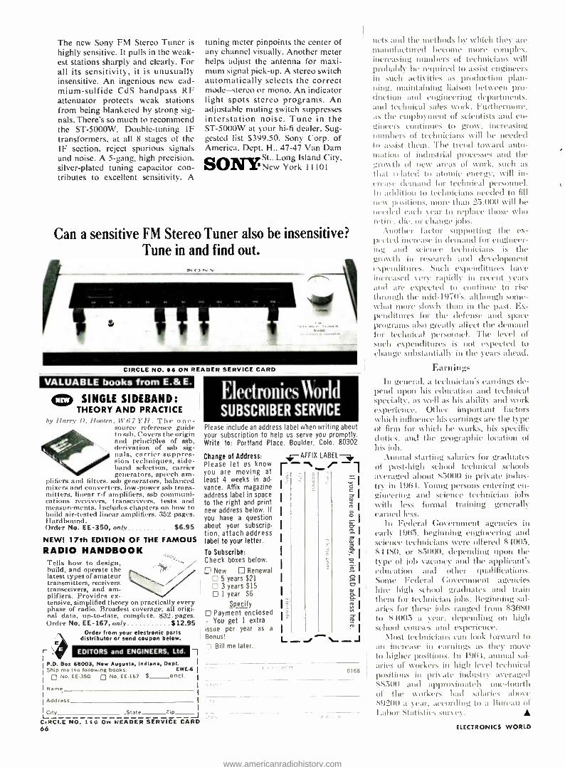
The new Sony FM Stereo Tuner is highly sensitive. It pulls in the weak- est stations sharply and clearly. For all its sensitivity, it is unusually insensitive. An ingenious new cad- mium- sulfide CdS Bandpass RF attenuator protects weak stations from being blanketed by strong sig- nals. There's so much to recommend the ST- 5000W. Double- tuning IF transformers, at all 8 stages of the IF section, reject spurious signals and noise. A 5 -gang, high precision. silver -plated tuning capacitor con- tributes to excellent sensitivity. A
tuning meter pinpoints the center of any channel visually. Another meter helps adjust the antenna for maxi- mum signal pick -up. A stereo switch automatically selects the correct mode -stereo or mono. An indicator light spots stereo programs. An adjustable muting switch suppresses interstation noise. Tune in the ST -5000W at your hi -fi dealer. Sug- gested list $399.50. Sony Corp. of America. Dept. H., 47 -47 Van Dam
SO11TYst.,
Long Island City, New York 1 1 101
Can a sensitive FM Stereo Tuner also be insensitive? Tune in and find out.
CIRCLE NO. 96 ON READER SERVICE CARD
VALUABLE books from E.& E.
SINGLE SIDEBAND: THEORY AND PRACTICE
by 11,rry I). Iluoten, tl'(ii YH. The one - source reference guide to ssb. Covers the origin and principles of ssb, derivation of ssb sig- nals, carrier suppres- sion techniques, side - band selection, carrier generators, speech am-
plifiers and filters. ssb generators, balanced mixers and converters, low -power ssb trans- mitters, linear r -f amplifiers, ssb communi- cations receivers, transceivers, tests and measurements. Includes chapters on how to build air -tested linear amplifiers. 352 pages. Hardbound. Order No. EE -350, on /y. $6.95
NEW! 17th EDITION OF THE FAMOUS RADIO HANDBOOK Tells how to design, build, and operate the latest types of amateur transmitters, receivers. transceivers, and am- plifiers. Provides ex- tensive, simplified theory on practically every phase of radio. Broadest coverage; all origi- nal data, up -to -date, complete. 832. pages. Order No. EE -167, only $12.95
Order from your electronic parts distributor or send coupon below.
r EDITORS and ENGINEERS, Ltd.
P.O. Box 68003, New Augusta, Indiana, Dept. Ship me the following books: EWE -6
o No. EE -350 o No. EE -167
Name
Address
City State Zip J
ElectronicsNorld SUBSCRIBER SERVICE
Please include an address label when writing about your subscription to help us serve you promptly. Write to: Portland Place. Boulder. Colo. 80302
Change of Address: Please let us know you are moving at least 4 weeks in ad- vance. Affix magazine address label in space to the right and print new address below. If you have a question about your subscrip- tion, attach address label to your letter.
To Subscribe: Check boxes below.
[I New Renewal 5 years $21 3 years $15 1 year $6
Specify Payment enclosed
- You get 1 extra issue per year as a
Bonus!
Bill me later.
0168
nets and the methods by which they are manufactured become more complex, increasing numbers of technicians will probably he required to assist engineers in such activities as production plan-
maintaining liaison between pro - duction and engineering clepartntcnts, and technical sales work. Furthermore, as the employment of scientists and en- gincers continues to grow, increasing unntl t rs of technicians will be needed to assist them. The trend toward auto - iIi Ltitm of industrial processes and the growth of new areas of work, such as
that related to utumic energy, will in- crease demand for technical personnel. In addition to technicians needed to fill new positions, more than 2..000 will be needed each car to replace those who retire. die. or change jobs.
:Another factor supporting the ex- pected increase in demand for engineer-
and science technicians is the gmo th in research and development expenditures. Such expenditures have increased very rapidly in recent years and are expected to continue to rise through the mid-1970's, although some- what more slowly than in the past. Ex- penditures for the defense and space programs also greatly affect the demand for technical personnel. The level of such expenditures is not expected to change substantially in the years ahead.
Earnings In general. a technician's earnings de-
pend upon his education and technical specialty, as well as his ability and work experience. Other important factors which influence his earnings are the type of firm for which he works, his specific duties. and the geographic location of his lob.
--Annual starting salaries for graduates of post -high school technical schools averaged about 55000 in private indus- try in 1964. Young persons entering en- gitu'criug and science technician jobs with less formal training generally earned less.
In Federal Government agencies in early 1965. beginning engineering and science technicians were offered $4005. 54480. or $5000, depending upon the type of job vacancy and the applicant's education and other qualifications. Some Federal Government agencies hire high school graduates anti train tllenl for technician jobs. Beginning sal- aries for these ¡ohs ranged from S3680 to $4005 a year. depending on high school courses and experience.
\lost technicians can look forward to ait increase in earnings as they move to higher positions. Ill 1964, annual sal- aries of vVurkers in high level technical positions in private industry averaged $8500 and approximately one -fourth of the workers had salaries above s!)200 a year. according to a Bureau of Labor Statistics stir\ ev .
CIRCLE NO. 116 Ow READER SERVICE CARD 66 ELECTRONICS WORLD
www.americanradiohistory.com

Highway Emergency Radio (Continued from page 42)
incorporates a triggering concept that works as follows. As the car hits a "magnetic transmitter ", logic circuits open the speaker of the CB rig for 8 to 10 seconds, just long enough for an upstream transmitter to broadcast a message concerning road conditions or accommodations ahead. Simultaneous- ly, the AM radio is muted. Cars travel- ing in the other direction are not triggered and hence do not receive this message. The transmitter need only be about 20 to 50 milliwatts and this neat- ly confines the range to a 500 -foot area, sufficient for adequate reception of two 4- second prerecorded messages to cars traveling at 75 mi /h. A remote cable- connected control would permit appropriate selection of the tape track at various times.
The "visual sign minder" is a com- bination light and alpha -numeric read- out -tube panel device which mounts on the dashboard and provides a "sign" corresponding to one posted on the roadway. An audio tone is sounded to gain the driver's attention. Passing over a magnetic code in the pavement triggers the display on the dash; the "sign" will light up with "25" for 25 mi /h, for example, in addition to con- ventional lights illuminating such mess- ages as "STOP," "YIELD," and "RR ".
The "route minder" operates on the IC memory unit principle, responding to unique identification of all intersec- tions. When the proper code is re- ceived from the buried magnets (as the driver approaches the intersection), the memory unit activates the sign minder panel device which then lights up "STRAIGHT," "LEFT," or "RIGHT" to alert the driver for proper turning. Again, an audible signal calls the driv- er's attention to the readout. Obviously, the magnetic coding here must be dif- ferent from that employed for other functions, so GM suggests using six magnets. The first three are for sign purposes; the remaining three are for intersection identification.
The "code and voice communica- tions" function uses 27 -MHz CB in a unique configuration. Utilizing a tele- phone -type dial encoder installed in the console, the driver dials the service needed: "1" for police, "2" for ambu- lance, "3" for fire truck, and "4" for tow truck. Then he dials the last three digits of his license -plate number and finally his location. This coded transmission is received at a relay station and passed on to the Aid and Information Center (AIC) by wire for added security. At the Center (Fig. 7) , the signal is de- coded, indicated on alpha- numeric read- out tubes, and printed for permanent record. The dispatcher sends for the
June, 1967
What's the best antenna headirg to hear a 6W8? What time is it in Zanzibar ?
How ma.-iy /RC's for a letter from a ZP? Are tie Dodecanese in Asia.' Is a c E i-I DX Zone 38? What's t+1e address of the
Veaezdela QSL Bureau ?
Fird all the answers fast with the BRAND -NEW
1Y910P'S ".-.......
SECOND OP
4TH EDITION OF W9IOP'S SECOND OP $1.00
Put vital world -wide DX data at your fingertips with this 101A" circular calculator. Shows beam headings, time differences, postal rates y DX zones, QSL bureaus, many more DX facts ... at a glance! The fully -revised 4th Edition is now at your nearby E -V ham microphone headquarters. Or send $1.00 today directly to us.
ELECTRO- VOICE, INC., Dept. 673N,_ 629 Cecil Street,
Buchanan, Michigan 49107
CIRCLE NO. 115 ON READER SERVICE CARD
It only sounds expensive!
The Shure M75E Hi -Track is a new high trackability cartridge made especially for those who are rich only fru music appreciaticn. This mocest y- priced cartridge will up- grade your entire stereo system by delivering live, natural souid from even diifficult -to -track records. Also featares a bi- radial elliptical stylus and built-in stylus guard. 11 grams maximum tracking. Only $29.50. Literature: SHURE BROTI -ERS, INC , 222 Hartrey Avenue, Evanston, Illinois 50204
SHt..JFRE M75E HI -TRACK Elliptical Stylus Cartridge For
3/4 to 11/2 Gram Tracking CIRCLE NO 89 ON READER SERVICE CARD
FROM
R ER pIIv', Model 65-3 VHF -TV ANTENNA AMPLIFIER improves reception of WEAK VHF -TV signals in FRINGE AREAS even where strong local TV or FM signals are present., AMPLIFIES UP TO 7 TIMES for Better Color and B/W
A two- transis- tor- amplifier. Engineered to provide the lowest noise and highest amplification with the most desirable over- load charac- teristics. Amplifier used in conjunction with dual out- let power sup- ply for one, two, or multi - ple set instal- lations. 117 V 60 cycle input. AC power up to amplifier:24 volts -60 cycle.
Let Finco solve your Color and B & W reception problems. Write for complete information, schematics and specifications. Form #20 -357.
Model 653 VHF-PI ANTENNA AMPLIFIER
1
THE FINNEY COMPANY 34 West Interstate St. Bedford, Ohio 44014 Dept.410
CIRCLE NO. 112 ON READER SERVICE CARD 67
www.americanradiohistory.com
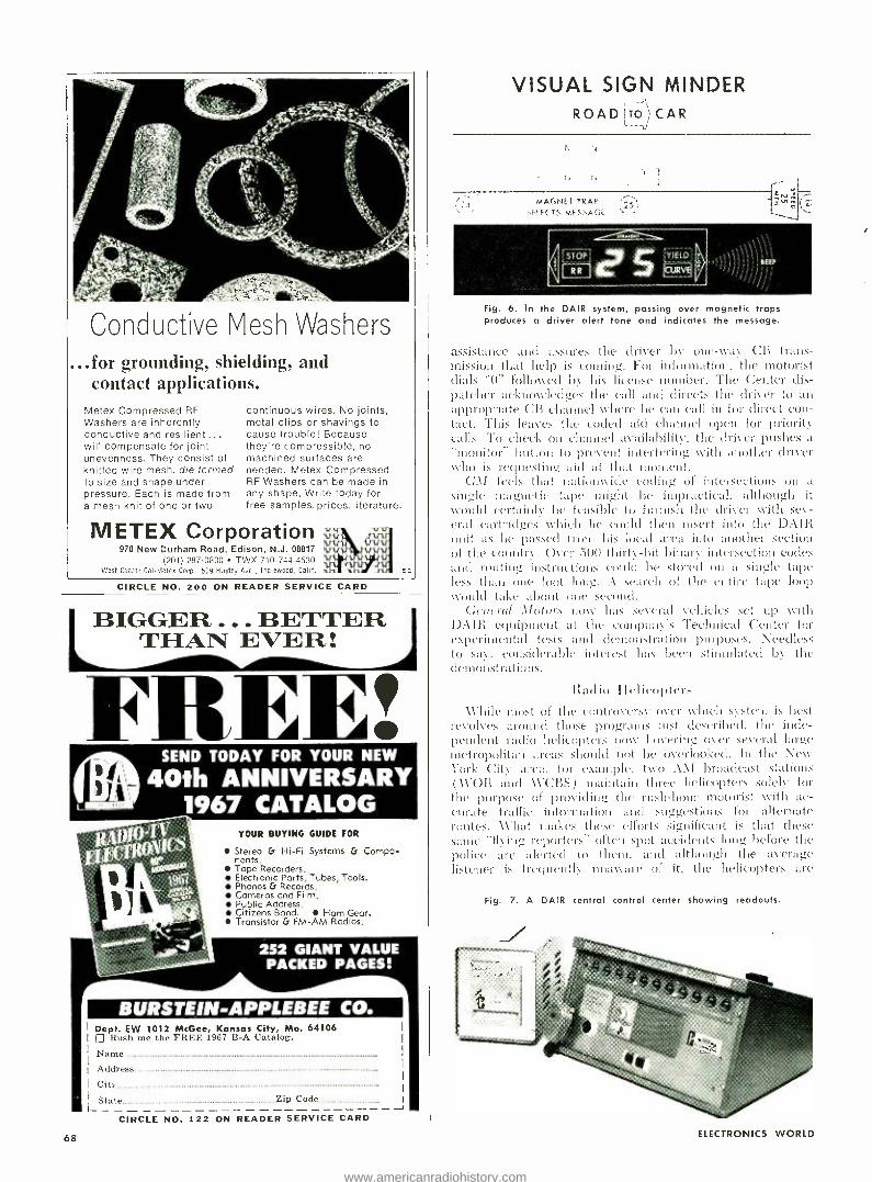
Conductive Vesh Washers ..for grounding, shielding, and
contact applications. Metex Compressed RF Washers are inherently conductive and resilient... will compensate for joint unevenness. They consist of knitted wire mesh, die formed to size and shape under pressure. Each is made from a mesh knit of one or two
continuous wires. No joints, metal clips or shavings to cause trouble! Because they're compressible, no machined surfaces are needed. Metex Compressed RF Washers can be made in any shape. Write today for free samples, prices, literature.
METEX Corporation 970 New Durham Road, Edison, N.J. 08817
(201) 287 -0800 TWX 710- 744 -4530 West Coast: Cal -Metes Coro., 509 Hendry Ave., Inglewood, Calif.
CIRCLE NO. 200 ON READER SERVICE CARD
BIGGER . . BETTER THAN EVER:
SEND TODAY FOR YOUR NEW
40th ANNIVERSARY 1967 CATALOG
YOUR BUYING GUIDE FOR
Stereo & Hi -Fi Systems & Compo- nents. Tape Recorders, Electronic Ports, Tubes, Tools. Phonos & Records. Cameras and Film. Public Address. Citizens Band. Horn Gear. Transistor & FM -AM Radios.
BURSTEIN-APPLEBEE CO. Dept. EW 1012 McGee, Kansas City, Mo. 64106
Rush me the FREE 1967 R -A Catalog.
Name
Address
City
State Zip Code
CIRCLE NO.
68
122 ON READER SERVICE CARD
VISUAL SiGN MINDER ROAD To CAR
MAGNEZ TRAP
SELECTS MESSAGE
Fig. 6. In the DAIR system, passing over magnetic traps produces a driver alert tone and indicates the message.
assistance and assures the driver by one -Ryas CB trans- mission that help is coming. For information, the motorist dials "0" followed by his license number. The Center dis- patcher acknowledges the call and directs the driver to an appropriate ( :n channel where he can call in for direct con- tact. This leaves the coded aid channel open for priority calls. To check on channel availability, the driver pushes a -monitor" button to prevent interfering with another driver who is requesting aid at that moment.
G_11 feels that nationwide coding of intersections on a
single magnetic tape alight be impractical, although it would certainly be feasible to furnish the driver with sev- eral cartridges which he could then insert into the DAIR unit as he passed from his local urea into another section of the country. Over 5(10 thirty-bit binary intersection codes and routing instructions could be stored on a single tape less than one foot long. A search of the entire tape loop would take about one second.
Gratin/ Motors now has several vehicles set up vyitli DAIR equipment at the company's Technical Center for experimental tests and demonstration purposes. Needless to say. considerable interest has been stimulated by the demonstrations.
Radio ilelicoltter) While most of the controversy over which system is best
revolves around those programs just described, the inde- pendent radio helicopters nose hovering Oser several large metropolitan areas should not be overlooked. ln the New York City area. for example. two A \I broadcast stations ( \V'OR and \V'C1iS) maintain three Helicopters solely for the purpose of providing the rush -hour motorist with ac- curate traffic' information ,nid suggestions for alternate routes. AV"hat makes these efforts significant is that these same "Hying reporters" often spot accidents long before the police are alerted to them. and although the average listener is frequently unaware of it, the Helicopters are
Fig. 7. A DAIR central control center showing readouts.
ELECTRONICS WORLD
www.americanradiohistory.com

responsible for obtaining a considerable amount of road assistance that other- wise would have necessitated the driver leaving his car, walking along a busy freeway, and telephoning for help. (One station now issues `HELP!" ban- ners to drivers for placing on car roofs when the vehicle conks out. Helicopters spot the signs and quickly radio for as- sistance. There is no charge for the service or the banners.)
But perhaps most important is the fact that at present helicopter reports are the only real source of up -to -date traffic news. If nothing else, they at least keep the motorist informed, which is more than anyone else is doing.
Central Traffic Control Centers The reader will note that most of the
two -way communications systems be- ing proposed rely to some extent on a central control center. This center could be fed information from smaller moni- toring stations, change transmitter codes, alter speed limits, and generally coordinate vehicular flow in high- densi- ty traffic areas, While many cities are currently working on small versions of this concept, the installation at the De- troit National Proving Ground for Free- way Surveillance is perhaps the most advanced. It serves as a headquarters during peak traffic hours for all kinds of information relating to vehicular flow and, using lane lights, can to some de- gree control sections of Detroit express - \vayS.
The control center ( Fig. 8) is pro- vided with CB equipment for taking calls from volunteer traffic reporters, a battery of telephones, and an impres- sive array of CCTV units for accurate surveillance of major arteries and trouble- spots. In addition, traffic coun- ters and police reports help to round out the incoming information.
What has been learned even with existing equipment is that if traffic flow can be maintained at a uniform pace, safety can be significantly improved.
\Vhatever form the control centers take, however, one thing is certain: they will ultimately have the responsibility for servicing any vehicular highway radio system that is expected to be used effectively for improving safety A
Fig. 8. In this typical freeway control center, extensive use is made of both Citizens Band and closed- circuit tele- vision systems. Locale is in Detroit.
June, 1967
ORGANIZE! DO IT NOW! __^'"':r , '.. x - aa
' -.--_. ..'-tr . -. _¡
MAGNETIC VISUAL CONTROL BOARDS SIMPLIFY WORK
COLORFUL MAGNETIC ELEMENTS
show facts instantly organize for action eliminate mistakes get the job done
MAGNETS MOVE FASTEST - AND EASIEST -OF ALL
WRITE FOR FREE 28 PAGE ILLUSTRATED CATALOG EW6
METHODS RESEARCH CORP. 24 WILLOW AVE., STATEN ISLAND, N.Y. 10305
CIRCLE NO. 199 ON READER SERVICE CARD
INTRODUCING THE NEW
fl c lÌ Lt's L f «tiP ri(/(m
Build it yourself and save over 50%
The only Theatre Organ available in kit form -for only $1350. You've asked for it and here it is - the NEW Schober THEATRE ORGAN that you as- semble yourself. for the first time in kit form, a real Theatre Organ with that rich, full. old time theatre pipe organ sound. You create the organ, then you create the music!
For years you've been able to buy organs in kit form from Schober: The Recital (fully AGO), the Consolette II (the best spinet organ available today) and the Spinet (for the most music at the lowest price). Now to join them, we present the Schober Theatre Organ.
The Schober Theatre Organ has the same quality features found on all Schober Organs, and in addition ... special voicing, curved console design, two 61 -note keyboards, octave radiating pedal clavier, 8 octaves of tone distributed over 5 pitch registers (includ- ing a l -foot register!), 35 speaking organ stops, 8 realistic percussion stops, 4 couplers, and vibrato tablet -48 tablets in all. And all at a truly remarkable low price ... you save over $1,500 (well aver 50 %) from comparable theatre organs.
Easy Step -By -Step Instructions. You'll enjoy assembling this authentic and
versatile instrument from transistor and mini- ature components too. Just follow easy step - by -step instructions written in everyday lan- guage which anyone can understand. You'll have an unequaled pride when you're finished that only can come from assembling it yourself.
And you'll have an organ you can learn to play easily and quickly -just follow one of the self teaching courses available from us.
The Theatre Organ price starts at $1,350, depending on the options you select. This price includes a beautiful walnut console (other woods available) or you can save an additional amount by building your own from plans available from us. Options available include combination action, genuine reverber- ation, percussion, and amplifiers and speakers.
A CON1I'LETE THEATRE ORGAN! All you do is have the fun of asscrribling
it from kits and detailed, step -by -step instructions.
Includes console, keyboards, bench, ped- als, electronics -everything you need ex- cept amplifier and speaker system, which are extra -or use your own. Percussions, combination action, and reverberation are options.
Features fully transistorized electronics. regulated power supplies, all printed cir- cuit construction and gold switch contacts.
Combination Action Ten buttons select preset combinations of stops- actually move the stop tablets as in fine pipe organs -to give instant total changes of tonal effects. You can alter the preset combina- tions any time you like. Action is brand new electro- pneumatic type - silent, de- pendable.
Percussion Eight percussion stops pro- vide exciting realism. Celesta, harpsichord, piano, mandolin, xylophone, chrysoglott, orchestral hells, single or reiterating, are played just like the real thing -and sound that way - alone or along with regular organ stops.
Uncompromising Organ Quality from Easy -to- Assemble Kits
Free Information. Send today for your free copy of Schober's 16 -page full -color booklet - plus free 7" recording -with full information on all Schober Organs, priced from $550.
rThe Schober Organ Corp., Dept. RN -50 43 West 61st St., New York, N. Y. 10023
Please send me Schober Organ Catalog and FREE. 7 -inch "sample" record. Enclosed please find $2.00 for I'_ -inch qual- ity LP record of Schober Organ music. ($2.00 refunded with purchase of first kit.)
Name
THE í'%í(7Yí :í917y2 CORPORATION
43 West 61st Street, New York. N.Y. 100'' !- -3 City
CIRCLE NO 99 ON READER SERVICE CARD
Address
State Zip No
69
www.americanradiohistory.com
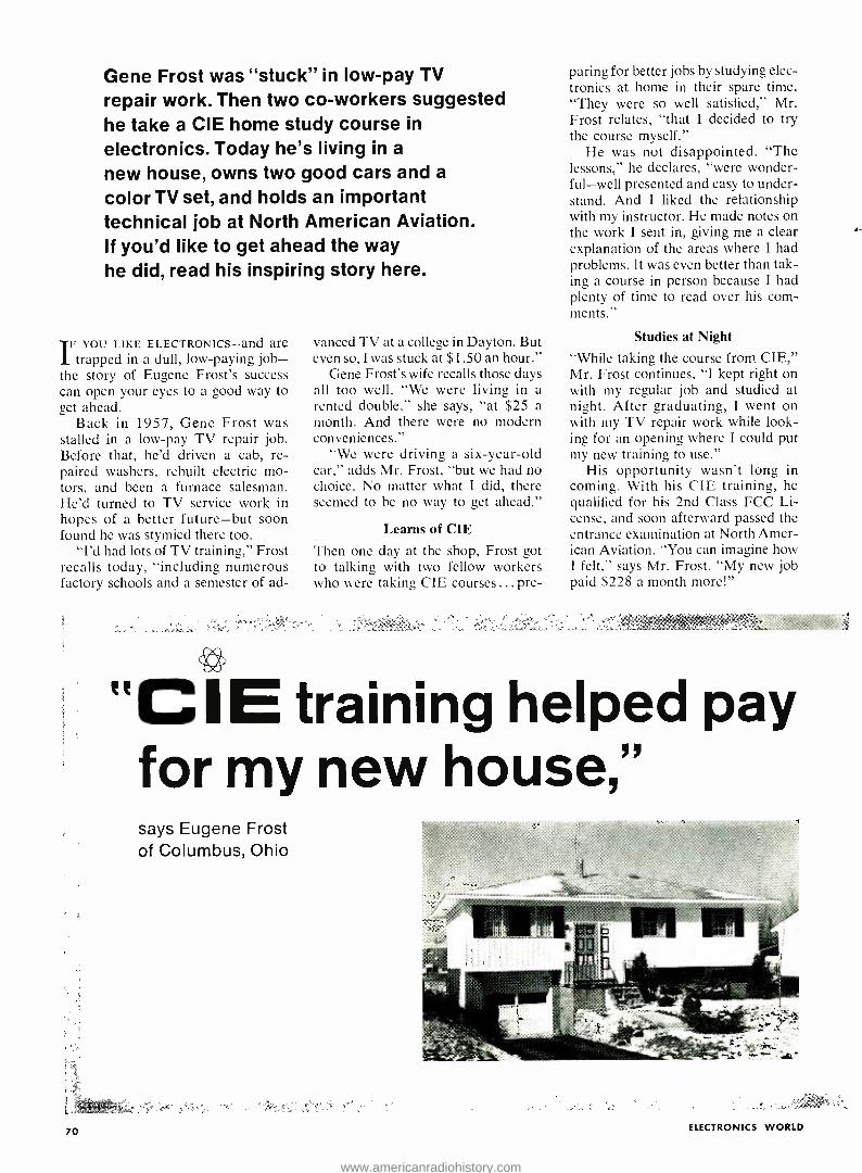
Gene Frost was "stuck" in low -pay TV repair work. Then two co- workers suggested he take a CIE home study course in
electronics. Today he's living in a
new house, owns two good cars and a
color TV set, and holds an important technical job at North American Aviation. If you'd like to get ahead the way he did, read his inspiring story here.
I FYOU LIKE ELECTRONICS -and are trapped in a dull, low- paying job -
the story of Eugene Frost's success can open your eyes to a good way to get ahead.
Back in 1957, Gene Frost was stalled in a low -pay TV repair job. Before that, he'd driven a cab, re- paired washers, rebuilt electric mo- tors, and been a furnace salesman. He'd turned to TV service work in hopes of a better future -but soon found he was stymied there too.
"I'd had lots of TV training," Frost recalls today, "including numerous factory schools and a semester of ad-
70
vanced TV at a college in Dayton. But even so, I was stuck at $1.50 an hour."
Gene Frost's wife recalls those days all too well. "We were living in a rented double," she says, "at $25 a month. And there were no modern conveniences."
"We were driving a six -year -old car," adds Mr. Frost, "but we had no choice. No matter what I did, there seemed to be no way to get ahead."
Learns of CIE
Then one day at the shop, Frost got to talking with two fellow workers who were taking CIE courses ... pre-
paring for better jobs by studying elec- tronics at home in their spare time. "They were so well satisfied," Mr. Frost relates, "that I decided to try the course myself."
He was not disappointed. "The lessons," he declares, "were wonder- ful -well presented and easy to under- stand. And 1 liked the relationship with my instructor. He made notes on the work I sent in, giving me a clear explanation of the areas where I had problems. It was even better than tak- ing a course in person because I had plenty of time to read over his com- ments."
Studies at Night
"While taking the course from CIE," Mr. Frost continues, "I kept right on with my regular job and studied at night. After graduating, I went on with my TV repair work while look- ing for an opening where I could put my new training to use."
His opportunity wasn't long in coming. With his CIE training, he qualified for his 2nd Class FCC Li- cense, and soon afterward passed the entrance examination at North Amer- ican Aviation. "You can imagine how I felt," says Mr. Frost. "My new job paid $228 a month more!"
"CIE training helped pay for my new house," says Eugene Frost of Columbus, Ohio
ELECTRONICS WORLD
www.americanradiohistory.com
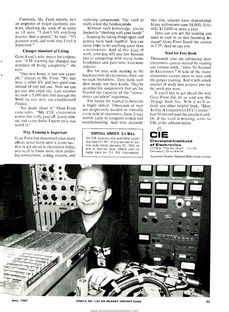
Currently, Mr. Frost reports, he's an inspector of major electronic sys- tems, checking the work of as many as 18 men. "I don't lift anything heavier than a pencil," he says. "It's pleasant work and work that I feel is important."
Changes Standard of Living
Gene Frost's wife shares his enthusi- asm. "CIE training has changed our standard of living completely," she says.
"Our new house is just one exam- ple," chimes in Mr. Frost. "We also have a color TV and two good cars instead of one old one. Now we can get out and enjoy life. Last summer we took a 5,000 mile trip through the West in our new air -conditioned Pontiac."
"No doubt about it," Gene Frost concludes. "My CIE electronics course has really paid off. Every min- ute and every dollar I spent on it was worth it."
Why Training is Important Gene Frost has discovered what many others never learn until it is too late: that to get ahead in electronics today, you need to know more than solder- ing connections, testing circuits, and
replacing components. You need to really know the fundamentals.
Without such knowledge, you're limited to "thinking with your hands" ...learning by taking things apart and putting them back together. You can never hope to be anything more than a serviceman. And in this kind of work, your pay will stay low because you're competing with every home handyman and part -time basement tinkerer.
But for men with training in the fundamentals of electronics, there are no such limitations. They think with their heads, not their hands. 'They're qualified for assignments that are far beyond the capacity of the "screw- driver and pliers" repairman.
The future for trained technicians is bright indeed. Thousands of men are desperately needed in virtually every field of electronics, from 2 -way mobile radio to computer testing and troubleshooting. And with demands
ENROLL UNDER a.I. BILL All CIE courses are available under the new G.I. Bill. If you served on ac- tive duty since January 31, '955, or are in service now, check box on reply card for G.I. Bill information.
like this, salaries have skyrocketed. Many technicians earn $8,000, $10; 000, $12,000 or more a year.
How can you get the training you need to cash in on this booming de- mand? Gene Frost found the answer in CIE. And so can you.
Send for Free Book Thousands who are advancing their electronics careers started by reading our famous book, "How To Succeed In Electronics." It tells of the many electronics careers open to men with the proper training. And it tells which courses of study best prepare you for the work you want.
If you'd like to get ahead the way Gene Frost did, let us send you this 40 -page book free. With it we'll in- clude our other helpful book, "How To Get A Commercial FCC License." Just fill out and mail the attached card. Or, if the card is missing, write to CIE at the address below.
CIE Cleveland Institute of Electronics 1776 E. 17th St., Dept. EW -33 Cleveland, Ohio 44114
Accredited Member National Home Study Council
June. 1967 CIRCLE NO. 120 ON READER SERVICE CARD 73
www.americanradiohistory.com

OISE" The World's Most
Trusted Name Brand VOLUME CONTROL & CONTACT RESTORER
TUNER -TONIC with PERMA -FILM
EC -44 FOR ELECTRICAL CONTACTS
TAPE -RECO HEAD CLEANER
FRIGID -AIR CIRCUIT COOLER
All Guaranteed Non -Flam- mable, No Carbon -Tet, Non - Toxic & Won't Affect Plastics
The Only Brand Perfect For Color TV and Black & White
FREE extender assembly for pin-
point application supplied with ALL NO -NOISE PRODUCTS.
Electronic Chemical Corp. 813 Communipaw Ave. / Jersey City, N. J. 07304
CIRCLE NO. 114 ON READER SERVICE CARD
SMALL BUI POWERFUL
DON'T BE FOOLED BY
IMITATIONS!
Get the ORIGINAL
' SYDMUR SOLID STATE "CD" IGNITION SYSTEM! High Quality Components used throughout. Fiberglass Printed Circuitt Board. Unitized Construction. Simplified Kit Assembly.
Construction Article in Nov. 1966 Popular Electronics Thousands of satisfied customers.
Write for Free Literature TODAY. COMPAC Assembled $34.75° COMPAC KIT 24.95°
*Add 75c for mailing and handling N.Y. State Residents add Sales Tax.
SYDMUR ELECTRONICS SPECIALTIES 1268 E. 12th St. Brooklyn, N.Y. 11230
PHOTOGRAPHY ANNUAL A selection of the World's finest photographs corn- piled by the editors of Popular Photography. All editions $1.25 each: 1966 - $1.25............#1
1967 - 51.50........, #38 1964 - $1.25............#3 Order by number from
Ziff -Davis Service Div., 595 Broadway New York, N. Y. 10012. Enclose add'( 15¢ per copy for ship- ping and handling (50¢ for orders outside U.S.A.)
LEARN Engineering AT HOME i.,x 7(, do,go lean, tramistoic.
mple_e electronics. College level Home Study taught can urvierstand theta. Earn 60 the highly paid electronics industry. Com-
puter,. lli -.l en. theory and practical. Kit, turni.lil 1.
e31.11111 graduate. employed. Resident
ia.es Chicago campus if , le.,irl I. Founded 1934. Cataro¢. "Vets -write for information about li I Bill Training."
American Institute of Engineering & Technology 1141 West Fullerton Parkway Chicago, III. 60614
74
Penultimate Automatic Keyer (Continued frone page 38)
tions which tell the computer what to do. Since the exact instructions depend on the particular computer used, we will not describe the exact program. Instead, we will describe what it does.
The computer program permits the operator to sit at the typewriter and "converse" with the computer. By typ- ing in the correct symbols, the operator tells the computer what to do. If the computer needs to tell the operator something, it merely types back on the same typewriter. In this way the opera- tor and the computer "converse" with each other.
To control the computer, there are five so- called control words which have a special meaning to the program run- ning the computer. These words start with a slash to tell the computer that the following word is a control word.
The five words are /REC, which tells the computer to receive a message from the keyboard and store it in the mem- ory for future sending. /ERS tells the computer to erase a previous message from its memory and /KEY tells the computer to send a message in code. To help the operator, /PRT tells the com- puter to print out on the typewriter all the messages stored in the computer, and /PUN tells the computer to prepare a tape of all messages inside the mem- ory. This tape is useful if we want to save the messages while we use the computer for something else.
To identify what is sent, received, or
erased, each of the messages in the memory has a name of up to four let- ters. For example, a message calling "CQ" would be called "CQ "; a message with the operator's name would be called "NAME "; a description of the station equipment might be called "EQPT "; the station address might be called "ADDR."
Fig. 5 shows the actual typewriter printout during a typical operation of the keyer. At the beginning, we store several messages in the computer with the /REC code. Just to make sure that they are in correctly, we "play them back" with the /PRT code. Finally, we use the /KEY code to actually send them over the air. To make it more ob- vious which of the typing is the opera- tor's and which is the computer's, we have underlined everything put in by the operator.
Any new invention, especially one which uses automation to replace a hu- man, is scorned and decried. We are sure that the same fate will befall our penultimate automatic keyer.
No doubt many amateurs will feel that they have been replaced by a ma- chine and that they are being forced out of a hobby rightfully theirs. They will claim that the computer, being but a machine, has no right to a hobby, es- pecially their hobby.
To these foolish souls we would like to point out that the computer program which makes the computer work is hardly designed to make the computer enjoy itself. After all, how would you, like it if you had to blink your eyes in time to Morse code for hours on end?
Fig. 5. Example of the conversation between the keyer and the operator during typical operation. (Operator answers to computer are underlined in this reduced actual printout.)
WHAT SPEED? 0005
/REC, /ERS, /KEY,
WHAT NAME ?
GO AHEAD.
CQ CO CQ CO CO CO DE WB2KYF WB2KYF WB2KYF SK
/REC, /ERS, /KEY, /PRT, /PUN? /REC
WHAT NAME? QTH
GO AHEAD.
OUR QTH IS IN BAYSIDE, NEW YORK.
/REC, /ERS, /KEY, /PRT, /PUN? /PRT
CO
CO CQ CQ CQ CQ CQ DE WB2KYF WB2KYF WB2KYF SK
QTH
OUR QTH IS IN BAYSIDE, NEW YORK.
/REC, /ERS, /KEY, /PRT, /PUN? /KEY
WHAT? ÇQ
/REC, /ERS, /KEY, /PRT, /PUN? /KEY
WHAT? CQ
/PRT, /PUN? /REC
ELECTRONICS WORLD
www.americanradiohistory.com
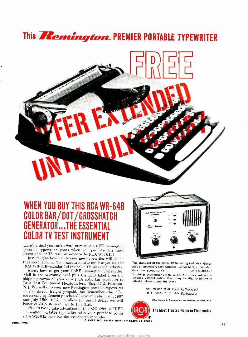
This PREMIER PORTABLE TYPEWRITER
WHEN YOU BUY THIS RCA WR -64B COLOR BAR /DOT /CROSSHATCH
GENERATOR ,,,THE ESSENTIAL
COLOR TV TEST INSTRUMENT Here's a deal you can't afford to miss! A FREE Remington portable typewriter -yours when you purchase the most essential color -TV test instrument -the RCA WR -64B!
Just imagine how handy your new typewriter will be -in the shop or at home. You'll use it almost as much as you use the RCA WR -64B- standard of the color TV servicing industry.
Here's how to get your FREE Remington Typewriter. Mail in the warranty card plus the gold label from the shipping carton of your new RCA color bar generator to RCA Test Equipment Headquarters, Bldg. 17 -2, Harrison, N. J. We will ship your new Remington portable typewriter to you direct, freight prepaid. But remember -this offer covers only equipment purchased between February 1, 1967 and July 15th, 1967. To allow for postal delay, we will honor cards postmarked up to July 31st.
Plan NOW to take advantage of this BIG offer -a FREE Remington portable typewriter with your purchase of an RCA WR -64B color bar /dot /crosshatch generator.
CIRCLE NO. 90 ON READER June, 1967
The standard of the Color -TV Servicing Industry. Gener- ates all necessary test patterns -color bars, crosshatch, dots plus sound -carrier. Only $189.50 °"
'Optional Distributor resale price. All prices subject to change without notice. Price may be slightly higher in Alaska, Hawaii, and the West.
Ask to see it at Your Authorized RCA Test Equipment Distributor
RCA Electronic Components and Devices, Harrison, N. J.
SERVICE CARD
The Most Trusted Name in Electronics
75
www.americanradiohistory.com
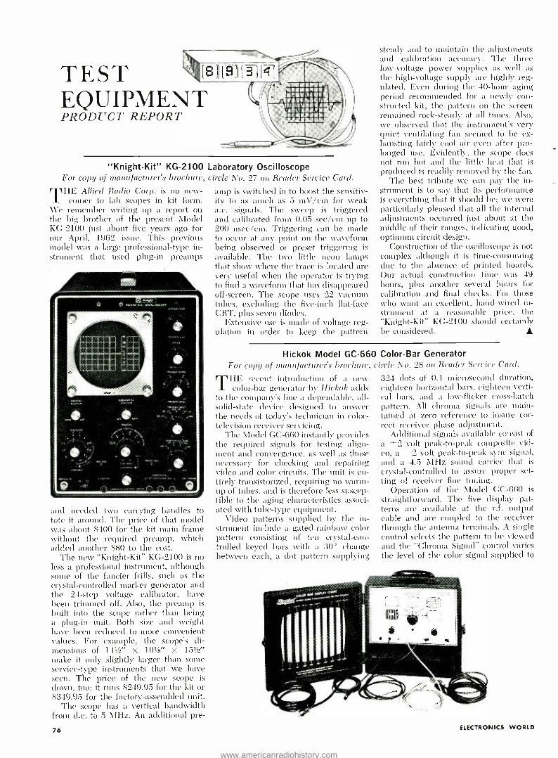
TEST EQUIPMENT
(8 9
- ( B )) ( 4
_
r.----,-
PRODUCT REPORT
%' =aaracr ,r aa /itifl% 1 %pt . .
"Knight -Kit" KG -2100 For copy of manufacturer's brochure,
THE Allied Radio Corp. is no new- comer to lab scopes in kit form.
We remember writing up a report on the big brother of the present Model KG -2100 just about five years ago for our April, 1962 issue. This previous model was a large professional -type in- strument that used plug -in preamps
and needed two carrying handles to tote it around. The price of that model was about $400 for the kit main frame without the required preamp, which added another $80 to the cost.
The new "Knight -Kit" KG -2100 is no less a professional instrument, although some of the fancier frills, such as the crystal- controlled marker generator and the 24 -step voltage calibrator, have been trimmed off. Also, the preamp is built into the scope rather than being a plug -in unit. Both size and weight have been reduced to more convenient values. For example, the scope's di- mensions of 141/2" X 10' /8" X 151/2" make it only slightly larger than some service -type instruments that we have seen. The price of the new scope is down, too; it runs $249.95 for the kit or $349.95 for the factory -assembled unit.
The scope has a vertical bandwidth from d.c. to 5 MHz. An additional pre-
76
Laboratory Oscilloscope circle No. 27 on Render Service Card.
amp is switched in to boost the sensitiv- ity to as much as 5 mV /cm for weak a.c. signals. The sweep is triggered and calibrated from 0.05 sec /cm up to 200 nsec /cm. Triggering can be made to occur at any point on the waveform being observed or preset triggering is available. The two little neon lamps that show where the trace is located are very useful when the operator is trying to find a waveform that has disappeared off- screen. The scope uses 22 vacuum tubes, excluding the five -inch flat -face CRT, plus seven diodes.
Extensive use is made of voltage reg- ulation in order to keep the pattern
steady and to maintain the adjustments and calibration accuracy. The three low -voltage power supplies as well as the high -voltage supply are highly reg- ulated. Even during the 40 -hour aging period recommended for a newly con- structed kit, the pattern on the screen remained rock -steady at all times. Also, the observed that the instrument's very quiet ventilating fan seemed to be ex- hausting fairly cool air even after pro- longed use. Evidently, the scope does not run hot and the little heat that is produced is readily removed by the fan.
The best tribute we can pay the in- strument is to say that its performance is everything that it should be; we were particularly pleased that all the internal adjustments occurred just about at the middle of their ranges, indicating good, optimum circuit design.
Construction of the oscilloscope is not complex although it is tine- consuming due to the absence of printed boards. Our actual construction time was 49 hours, plus another several hours for calibration and final checks. For those who want an excellent, hand -wired in- strument at a reasonable price, the "Knight -Kit" KG -2100 should certainly lie considered.
Hickok Model GC -660 Color -Bar Generator For copy of manufacturer's brochure, circle No. 28 on Reader Semite Card.
THE recent introduction of a new color -bar generator by Hickok acids
to the company's line a dependable, all - solid -state device designed to answer the needs of today's technician in color - television receiver servicing.
The Model GC -660 instantly provides the required signals for testing align- ment and convergence, as well as those necessary for checking and repairing video and color circuits. The unit is en- tirely transistorized, requiring no warm - up of tubes, and is therefore less suscep- tible to the aging characteristics associ- ated with tube -type equipment.
Video patterns supplied by the in- strument include a gated- rainbow color pattern consisting of ten crystal -con- trolled keyed bars with a 30° change between each, a dot pattern supplying
324 dots of 0.1 microsecond duration, eighteen horizontal bars, eighteen Verti- cal bars, and a low- flicker cross -hatch pattern. All chroma signals are main- tained at zero reference to insure cor- rect receiver phase adjustment.
Additional signals available consist of a ±2 volt peak -to -peak composite vid- eo, a 2 volt peak -to -peak sync signal, and a 4.5 ì\1Hz sound carrier that is
crystal -controlled to assure proper set- ting of receiver fine tuning.
Operation of the Model GC -660 is
straightforward. The five display pat- terns are available at the r.f. output cable and are coupled to the receiver through the antenna terminals. A single control selects the pattern to be viewed and the "Chroma Signal" control varies the level of the color signal supplied to
ELECTRONICS WORLD
www.americanradiohistory.com
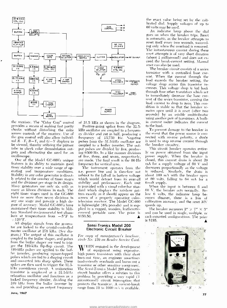
-R ^ B - G
1378 KHZ1 XTAL OSC
BUFFER
189 KHZ FLIP -FLOP
BUFFER
131.5KHz 6
115.75 KHZ i2
H. SYNC.
1
SHAPER
V. BAR SHAPER
DOT GATE
SHAPER
420 HZ i3
60HZ +7
CO GATE
LOR
13. MH XTAL
56 OSCZ .
H. BAR GATE
V. SYNC SHAPER
PATTE SELECTORN R
H BAR SHAPER
y
SYNC. MATRIX
the receiver. The "Color Gun" control provides a means of making fast purity checks without disturbing the color screen controls of the receiver. Use of the gun control will also allow individ- ual R -Y, B -Y, and G -Y displays to be viewed, thereby utilizing the picture tube to check color demodulation out- puts and eliminating the need for an oscilloscope.
One of the Model GC -660's unique features is its ability to maintain good timer stability over a wide range of op- erating and temperature conditions. Stability in any color generator is direct- ly related to the number of timer stages and the divisions per stage in its design. Many generators use only six with as many as fifteen divisions in each. The eight tinier stages used in the GC -660 have no more than seven divisions in any one stage and provide a high de- gree of accuracy. Model CC -660's have maintained their timer stability in Mili- tary Standard environmental test cham- bers at temperatures from -5 °F to +120 °F.
All display signals from the genera- tor are locked to the crystal -controlled master oscillator at 378 kHz. (See dia- gram.) The output of this oscillator is coupled to the buffer shaper, and pulses from the buffer shaper are used to trig- ger the 189 -kHz flip -flop circuit. The 189 -kHz pulses are applied to the buf- fer inverter, producing square- topped pulses which are fed to a shaping circuit and converted into sharp spikes. These spikes are then used to trigger the 31.5 - kHz countdown circuit. A unijunction transistor is employed as a 31.5 -kHz relaxation oscillator and functions as a locked frequency divider, dividing the 189 kHz from the buffer inverter by six and providing an output frequency
June, 1967
VIDEO -SYNC. MATRIX
1
GUN CONTROL
CLIPPER
I RF.OSC. CH. 3-4-5
MODULATOR
PHASE SPLITTER
4.5MHZ XTAL OSC.
RF OUTPUT
VIDEO COMppgITE FOLLOWER VIDEO OUTPUT
SYNC. FOLLOWER
POWER SUPPLY
~ OUTPUT
of 31.5 kHz as shown in the diagram. Positive -going spikes from the 31.5 -
kHz oscillator are coupled to a frequen- cy divider and cut in half, producing a frequency of 15,750 Hz. Negative pulses from the 31.5 -kHz oscillator are coupled to a buffer inverter. The out- put pulses are divided by five, produc- ing 6300 Hz. In a like manner divisions of five, three, and seven, respectively, are made. The final result is the 60 -Hz frequency for vertical sync.
The instrument operates from the a.c. power line and is therefore not subject to the fall -off in battery voltage which would detract from its over -all stability and performance. Each unit is provided with a visual color -bar stan- dard which displays the rainbow pat- tern exactly as it should appear on the screen of a properly operating color - television receiver. The Model GC -660 is lightweight (61/4 pounds) and is sup- plied in a rugged, wooden, leatherette - covered portable case. The price is $159.50. A
Sensi -Tronics Model 200 Electronic Circuit Breaker
For copy of manufacturer's brochure, circle No. 1.59 on Reader Service Card.
WHEN engaged in the development WHEN equipment using expensive,
high -power transistors with their short burn -out time, an engineer sometimes inadvertently overloads and burns out a transistor or other sensitive comp :men;. The Scnsi- Tronics Model 200 electronic circuit breaker offers a solution to this problem by providing a very rapid (1 microsecond) circuit interruption that protects the transistor. A current -break range from 10 to 1000 mA is available,
the exact value being set by the cali- brated dial. Supply voltages of up to 60 volts may be used.
An indicator lamp above the dial goes on when the breaker trips. Reset is automatic, as the breaker attempts to reset itself every two seconds, succeed- ing only when the overload is removed. The instantaneous current during these reset attempts is of very short duration (about 1 millisecond) and does not ex- ceed the break -current setting. Manual reset can also be used.
The breaker circuit consists of a series transistor with a controlled base cur- rent. When the current through the load exceeds the breaker setting, the voltage drop across this transistor in- creases. This voltage drop is fed back through four other transistors which act to immediately decrease the base cur- rent of the series transistor, causing the load current to drop to zero. This con- dition is stable so that the breaker re- mains open until it is reset (after two seconds) by an astable multivibrator using another pair of transistors. A built - in current meter indicates the current to the load.
To prevent damage to the breaker in the event that the power source is con- nected with reverse polarity, a diode is used to stop reverse current through the breaker circuitry.
This circuit breaker operates entire- ly on power obtained from the input power supply. When the breaker is closed, this current drain is about 20 mA for a supply voltage of 60 V and decreases proportionally as the voltage is reduced. Similarly, the drain is about 100 mA with the breaker open at 60 volts, falling to 64 mA for a 6 -volt supply.
When the input is between 6 and 60 V, the breaker acts normally. Be- low 6 volts, the indicator lamp be- comes dimmer, there is a loss of calibration accuracy, and the reset MV speeds up.
The breaker measures 3" x 7" X 3" and can be used in single, multiple, or rack-mounted configurations. The price is $185.
77
www.americanradiohistory.com
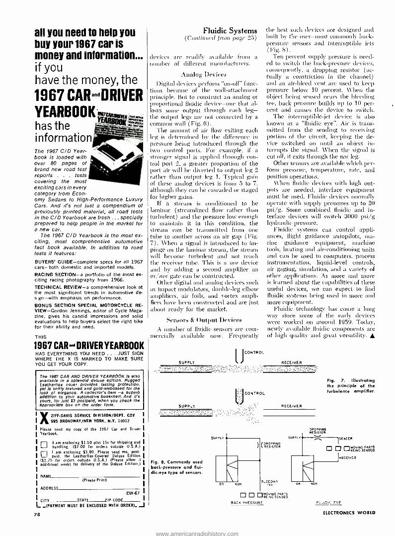
an you need to help you buy your 1967 car is money and information... if you have the money, the
1967 CARandDRIVER
YEARBOOK cNr tvER rEEEpM
has the Kw informations =` The 1967 C/D Year- book is loaded with over 80 pages of brand new road test reports . . . tests covering the most exciting cars in every category from Econ- omy Sedans to High- Performance Luxury Cars. And it's not just a compendium of previously printed material, all road tests in the C/D Yearbook are fresh ... specially prepared to help people in the market for a new car.
The 1967 C/D Yearbook is the most ex- citing, most comprehensive automotive fact book available. In addition to road tests it features:
BUYERS' GUIDE -complete specs for all 1967 cars -both domestic and imported models.
RACING SECTION -a portfolio of the most ex- citing racing photography from 1966.
TECHNICAL REVIEW -a comprehensive look at the most significant trends in automotive de- sign -with emphasis on performance.
BONUS SECTION SPECIAL MOTORCYCLE RE- VIEW- Gordon Jennings, editor of Cycle Maga- zine, gives his candid impressions and solid evaluations to help buyers select the right bike for their ability and need.
THIS
1967 CAR-a DRIVER YEARBOOK HAS EVERYTHING YOU NEED ... JUST SIGN WHERE THE X IS MARKED TO MAKE SURE YOU GET YOUR COPY.
The 1967 CAR AND DRIVER YEARBOOK is also available in a splendid deluxe edition. Rugged Leatherilex cover provides lasting protection, yet is softly textured and gold- embossed for the look of elegance. A collector's item -a superb addition to your automotive bookshelf. And it's yours, for just $3 postpaid, when you check the appropriate box on the order form.
XZIFF -DAVIS SERVICE DIVISION /DEPT. CDY
595 BROADWAY /NEW YORK, N.Y- 10012
Please send my copy of the 1967 Car and Driver Yearbook.
I am enclosing $1.50 plus 15c for shipping and ri handling. ($2.00 for orders outside U.S.A.) 1 am enclosing $3.00. Please send me, post- paid, the Leatherilex- Covered Deluxe Edition
($3.75 for orders outside U.S.A.) (Please allow 3
additional weeks for delivery of the Deluxe Edition.)
NAME (Please Print)
ADDRESS EW -67
CITY STATE 7IP CODE_
L _(PAYMENT MUST BE ENCLOSED WITH ORDER). .J 78
Fluidic Systems (Continued from page 25)
devices are readily available from a number of different manufacturers.
Analog Devices Digital devices perform "on -off" func-
tions because of the wall- attachment principle. But to construct an analog or proportional fluidic device -one that al- lows some output through each leg - the output legs are not connected by a common wall ( Fig. 6) .
The amount of air flow exiting each leg is determined by the difference in pressure being introduced through the two control ports. For example, if a stronger signal is applied through con- trol port 2, a greater proportion of the port air will be diverted to output leg 2 rather than output leg 1. Typical gain of these analog devices is from 5 to 7, although they can be cascaded or staged for higher gains.
If a stream is conditioned to be laminar (streamlined flow rather than turbulent) and the pressure low enough to maintain it in this condition, the stream can be transmitted from one tube to another across an air gap ( Fig. 7). When a signal is introduced to im- pinge on the laminar stream, the stream will become turbulent and not reach the receiver tube. This is a nor device and by adding a second amplifier an or /nor gate can be constructed.
Other digital and analog devices such as impact modulators, double -leg elbow amplifiers, air foils, and vortex ampli- fiers have been constructed and are just about ready for the market.
Sensors & Output Devices A number of fluidic sensors are cotn-
mercially available now. Frequently
SUPPLY
SUPPLY
\
JcONTROL
the best such devices are designed and built by the user -most commonly back - pressure sensors and interruptible jets (Fig. 8).
Ten -percent supply pressure is need- ed to switch the back -pressure devices, consequently, a dropping resistor ( ac- tually a constriction in the channel) and an air -bleed vent are used to keep pressure below 10 percent. When the object being sensed nears the bleeding tee, back pressure builds up to 10 per- cent and causes the device to switch.
The interruptible -jet device is also known as a "fluidic eye ". Air is trans- mitted from the sending to receiving portion of the circuit, keeping the de- vice switched on until an object in- terrupts the signal. When the signal is cut off, it exits through the nor leg.
Other sensors are available which per- form pressure, temperature, rate, and position operations.
When fluidic devices with high out- puts are needed, interface equipment must be used. Fluidic devices normally operate with supply pressures up to 20 psi /g. Some combined fluidic and in- terface devices will switch 3000 psi /g hydraulic pressure.
Fluidic systems can control appli- ances, flight guidance autopilots, ma- rine guidance equipment, machine tools, heating and air- conditioning units and can be used in computers, process instrumentation, liquid -level controls, air gaging, simulation, and a variety of other applications. As more and more is learned about the capabilities of these useful devices, we can expect to find fluidic systems being used in more and more equipment.
Fluidic technology has come a long way since some of the early devices were worked on around 1959. Today, newly available fluidic components are of high quality and great versatility. A
RECEIVER
CONTROL
RECEIVER
Fig. 7. Illustrating the principle of the turbulence amplifier.
Fig. 8. Commonly used back -pressure and flui- dic -eye type of sensors.
DROPPING RESISTPIOR
3L EEDiND TEE
SUPPLY
DROPPING RESISTOR
Cl
'SENDER
Ell122UVLi !RECEIVER
R NOR
BACK PRESSURE
BEING SENSED
FLUIDIC EYE
ELECTRONICS WORLD
www.americanradiohistory.com
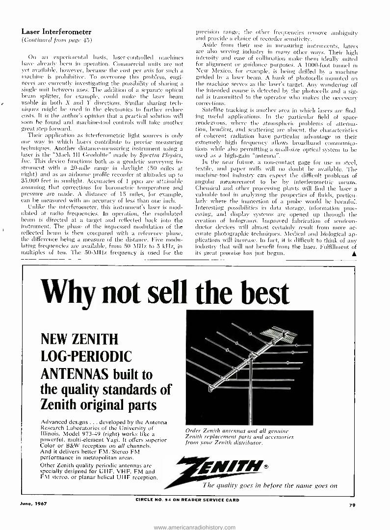
Laser Interferometer (Continued frone page 45)
On an experimental basis, laser -controlled machines have already been in operation. Commercial units are not yet available, however, because the cost per axis for such a machine is prohibitive. To overcome this problem, engi- neers are currently investigating the possibility of sharing a single unit between axes. The addition of a separate optical beam splitter, for example, could make the laser beam usable in both X and Y directions. Similar sharing tech- niques might be used in the electronics to further reduce costs. It is the author's opinion that a practical solution will soon be found and machine -tool controls will take another great step forward.
Their application as interferometric light sources is only one way in which lasers contribute to precise measuring techniques. Another distance -measuring instrument using a laser is the "Mach III Geodolite" made by Spectra Pliysics, Inc. This device functions both as a geodetic surveying in- strument with a 20 -mile range in daylight (50 miles at night) and as an airborne profile recorder at altitudes up to 35,000 feet in sunlight. Accuracies of 1 ppm are attainable assuming that corrections for barometric temperature and pressure are made. A distance of 15 miles, for example, can be measured with an accuracy of less than one inch.
Unlike the interferometer, this instrument's laser is mod- ulated at radio frequencies. In operation, the modulated beam is directed at a target and reflected back into the instrument. The phase of the impressed modulation of the reflected beam is then compared with a reference phase, the difference being a measure of the distance. Five modu- lating frequencies are available, from 50 NlHz to 5 kHz, in multiples of ten. The 50 -MHz frequency is used for the
precision range; the other frequencies remove ambiguity and provide a choice of recorder sensitivity.
Aside from their use in measuring instruments, lasers are also serving industry in many other ways. Their high intensity and ease of collimation make them ideally suited for alignment or guidance purposes. A 1000 -foot tunnel in New Mexico, for example, is being drilled by a machine guided by a laser bean. A bank of photocells amounted on the machine serves as the laser's target. Any wandering off the intended course is detected by the photocells and a sig- nal is transmitted to the operator who makes the necessary corrections.
Satellite tracking is another area in which lasers are find- ing useful applications. In the particular field of space rendezvous, where the atmospheric problems of attenua- tion, bending, and scattering are absent, the characteristics of coherent radiation have particular advantage as their extremely high frequency allows broadband communica- tions while also permitting a small -size optical system to be used as a high -gain "antenna ".
In the near future, a non- contact gage for use in steel, textile, and paper mills will no doubt be available. The machine -tool industry can expect the difficult problems of angular measurement to be by interferometric means. Chemical and other processing plants will find the laser a valuable tool in analyzing the properties of fluids, particu- larly where the immersion of a probe would be harmful. Interesting possibilities in data storage, information proc- essing, and display systems are opened up through the creation of holograms. Improved fabrication of semicon- ductor devices will almost certainly result from more ac- curate photographic techniques. Medical and biological ap- plications will increase. In fact, it is difficult to think of any industry that will not benefit from the laser. Fulfillment of its great promise has just begun.
Why not sell the best NEW ZENITH LOG-PERIODIC ANTENNAS built to the quality standards of Zenith original parts Advanced designs ... developed by the Antenna Research Laboratories of the University of Illinois. Model 973 -49 (right) works like a powerful, multi- element Yagi. It offers superior Color or B &W reception on all channels. And it delivers better FM /Stereo FM performance in metropolitan areas. Other Zenith quality periodic antennas are specially designed for UHF. VHF. FM and FM stereo. or planar helical UHF reception.
Order Zenith antennas and all genuine Zenith replacement parts and accessories from your Zenith distrihutor.
The quality goes in before quality goes in before the name goes on
CIRCLE NO. 94 ON READER SERVICE CARD June, 1967 79
www.americanradiohistory.com

FROM HiFi STEREO REVIEW
DELUXE PADDED
DUST -PROOF RECORD
AND TAPE CASES plus FREE cataloging forms
Arr-4111 ! These decorative, yet sturdily con- structed cases are just what you've been looking for to keep your records and tapes from getting tossed about and damaged, disappearing when you want them most and just generally getting the "worst of it" from constant handling. They're ideal too for those valuable old "78's" that always seem to get thrown about with no place to go.
Constructed of reinforced fiberboard and covered in rich leatherette in your choice of nine dec- orator colors, the HIFI /STEREO REVIEW Record and Tape Cases lend themselves handsomely to the decor of any room, whether it be your library, study, den, music room or pine -paneled garage. The padded leatherette back (in your color choice) is gold tooled in an exclusive design available only on HIFI /STEREO REVIEW Record and Tape Cases. The sides are in standard black leatherette to keep them looking new after con- stant use. With each Record and Tape Case you
order you will receive, free of charge, a specially designed record and tape cataloging form with pressure- sensi- tive backing for affixing to the side of each case. It enables you to list the record names and artists and will prove an invaluable aid in helping you locate your albums. The catalog form can be removed from the side of the case at any time without damaging the leath- erette.
Record Cases are available in three sizes: for 7 ", 10" and 12" records. Each case, with a center divider that separates your records for easy acces- sibility, holds an average of 20 records in their original jackets. The Recording Tape Case holds 6 tapes in their original boxes.
The Tape Cases and the 7" Record Cases (with catalog forms) are only $3.25 each; 3 for $9; 6 for $17.
The 10" and 12" Record Cases (with catalog forms) are $3.50 each; 3 for $10; 6 for $19.
Add an additional 75c per order (regardless of number of cases ordered) for shipping and handling.
WM
80
Ziff -Davis Publishing Company, Dept. SD One Park Avenue, New York, N. Y. 10016 My remittance in the amount of $ is enclosed for the Cases indicated below,
Quantity Tape Case at $3.25 each; 3 for $9; 6 for $17. 7" Record Case at $3.25 each; 3 for $9; 6 for $17. 10" Record Case at $3.50 each; 3 for $10; 6 for $19. 12" Record Case at $3.50 each; 3 for $10; 6 for $19.
Add 75c PER ORDER for SHIPPING and HANDLING
Check color choice for back of case (sides in black only):
Midnight Blue Red Saddle Tan Pine Green Orange Yellow Grey Black Spice Brown
Name
Address r
City State lip Code PAYMENT MUST BE ENCLOSED WITH ORDER MIN
Crystal Sideband Filter (Continlu'd fiotti pag(' 41
duce a passable characteristic curve but this will by no means be the most desirable one.
Sweep- Generator Method The use of a sweep generator, in
conjunction with a scope, is perhaps the simplest and most effective way of aligning a filter of the type described. The circuit of a simple sweep generator used by the author for alignment work is shown in Fig. 7. The arrangement works admirably and gives the builder a visual check as to the effects of the various adjustments on the filter char- acteristic curve. At this point it may be worthwhile to digress briefly and pre- sent a few pertinent details regarding the generator.
The sweep generator circuit is one adapted from a circuit which appeared ill the May, 1965 issue of -Wireless World." The circuit parameters have been selected for a sweep voltage in- put Of approximately 8 volts peak which is obtainable from a number of widely used measuring scopes. A sweep range of about 25 kHz is obtainable.
0
10
2.8 kHz
To set the sweep generator up, first adjust coil L1 with the trimmer ca- pacitor set to maximum, for oscilla- tions at 450 kHz. A broadcast receiver can be used for listening to the second harmonic on 900 kHz. With the mini- mum frequency set, apply a direct voltage, equal to the peak sweep input voltage that will be used, to the sweep input connection and set the deviation control pot to give a deviation of 25 kHz. The 475-kHz signal can be checked on the broadcast receiver at its second harmonic of 950 kHz.
The low cost and few minutes re- quired to assemble the simple i.f. sweep generator will more than compensate the builder in the time saved in aligning the sideband filter. It will also provide the experimenter with a useful piece of test equipment for receiver i.f. align- ment as well, especially if a crystal fil- ter is incorporated in the receiver that is used.
In using the sweep generator and scope to align the filter, the interim ad- justments described previously can be made to establish a convenient starting point. With the sweep generator and scope connected to the filter one need only make the necessary adjustments and watch the scope. The trimmers
CARRIER
40
459 460 461 462 463 464 465 466 467 468 FREQUENCY -kHz
Fig. 7. Complete cir- cuit diagram of the test sweep generator used by the author to develop the response curve of the filter.
8 TOIOV SAWTOOTH
INPUT
25k
6.8k
Llll
LI
a i1
291305
Fig. 6. The passband characteristics of the ferrite coil and crys- tal sideband filter are shown here after all the adjustments have been correctly made. Note the position of the carrier along the steep h.f. skirt.
390
a
4.7k 4.7k
IOk
04 22k PF
LI - MILLER 06300
IOU PF
5k
291305
330
8
040F
T)
04yF
fio- -o -129
25g
OUTPUT 450 -4750Hí
+12V o
www.americanradiohistory.com

35 fascinating ways to spend your next 250 spare hours Announcing the Spring 1967 edition of the " what- to -do- with -your -spare- time" prob- lem- solver: the ELECTRONIC EXPERI- MENTER'S HANDBOOK!
r Roll up your sleeves, heat up the iron and get set to meet 35 of the most chal- lenging, fun -to -build electronics projects you've ever seen - or assembled with your own two hands!
Included are: a transistorized auto -light minder a $2 intrusion alarm a tape recorder echo chamber (for under $10!)
a powerhouse 2 -tube SW receiver a solid -state scope calibrator and even a supercharged salt shaker!
You get complete schematics, illustra- tions, parts lists and easy -to- follow instructions ...
PLUS expert tips 'n techniques designed to build your electronics skill. You'll keep up with the latest advances in the field, learn many valuable professional meth- ods and short -cuts ... and develop that extra technical know-how that comes only from practical, firsthand experience.
Don't chance missing your copy of the Spring 1967 ELECTRONIC EXPERIMENT- ER'S HANDBOOK. Use the coupon below to order yours today! only $1.25
Get the handsome LEATHERFLEX- BOUND edition for just $3 postpaid! The Spring 1967 ELECTRONIC EXPERIMENTER'S HANDBOOK is also available in a splendid deluxe edition. Rugged Leatherflex cover provides lasting protection yet is softly textured and gold- embossed for the look of elegance. A collector's item -a superb addition to your elec- tronics bookshelf. And it's yours, for just $3 postpaid, when you check the appropriate box on the order form.
nn
and coils should be adjusted until a characteristic curve that is similar to the one that is illustrated in Fig. 6 is ob- tained.
It may be of interest to know that the trimmer adjustment of the secon- dary of the i.f. transformer Ti has more effect on the filter output ampli- tude than on the characteristic curve. The adjustments made to i.f. transform- er T2 affect the output level of the am- plifier stage only. The seven adjust- ments which are the most critical nil shaping of the characteristic curve are the adjustments to L1 and L2, the crystal trimmer capacitors, and the trimmer adjustment of the primary of the i.f. transformer Tl. The crystal trimmers across the high-frequency crystal will have a pronounced effect on the high -frequency side slope of the filter curve and Cite versa for the low- frequency crystal trimmers. The basic filter adjustments may require repeti- tive adjustment because they interlock slightly.
As can be noted from the filter curve, there is approximately a 6 -d13 sag or difference in the peaks of the filter pass - band. This sag causes no impairment of the voice quality, however. Needless to say, the visual display of the filter characteristic curve will also provide information relative to the amount of sideband rejection obtainable. By checking the passband one can readily deterIlline the relative position for the
CIRCLE NO. 103 carrier oscillator frequency. For the crystals used this frequency should be approximately 466 kHz.
Initial operational tests of the ferrite coil and crystal sideband filter have been made in an experimental 160 - meter sideband transmitter. The results of the test have proven the effective- ness of the filter. Construction of the described filter will provide you with an excellent starting point as well as the heart of your new -home- brew" side - band transmitter.
1 v1.1a/w Enjoy the "music- only" programs
now available on the FM broadcast band from coast to coast.
NO COMMERCIALS NO INTERRUPTIONS
It's easy! Just plug Music Associated's Sub Carrier Detector into multiplex jack of your FM tuner or easily wire into discriminator. Tune through your FM dial and hear programs of con- tinuous, commercial -free music you are now missing. The Detector, self- powered and with electronic mute for quieting between selections. permits reception of popular background music programs no longer sent by wire but transmitted as hidden programs on the FM broadcast band from coast to coast. Use with any FM tuner. Size 51/2" n 9 ". Shipping weight approx. 7 lbs.
KIT $4950 /with pre -tuned coils, no alignment necessaiyl
WIRED $7500 COVER $4.95 EXTRA Current List of FM Broadcast Stations with SC/a authorizat ion S
MUSIC ASSOCIATED 65 Glenwood Road, Upper Montclair, New Jesse,
Phone: 1201)- 744 -3387
7 - '1'.1.'.1.- .1.
ON READER SERVICE CARD
ZIFF -DAVIS SERVICE DIVISION DEPT. EEH -S 595 Broadway New York, N. Y. 10012 OK! Send me the all -new SPRING 1967 ELECTRONIC EXPERIMENTER'S HANDBOOK.
$1.25 enclosed, plus 15c for shipping and han- dling. Send me the regular edition. ($1.75 for orders outside the U.S.A.) $3.00 enclosed. Send me the Deluxe Leatherflex- bound edition, postpaid. ($3.75 for orders out- side the U.S.A.) Allow three additional weeks for delivery.
name please print
address
city state zip I - PAYMENT MUST BE ENCLOSED WITH ORDER -I I Boy, do I have spart time! Send me the big Fall t 1966 edition, too! I want the regular edition I ] Deluxe Leatherflex -bound edition. (Prices same
as above.) L
June, 1967
"Forget the Supreme Court ruling! Around here you have to admit when you're wrong!"
with Greenlee
punches Here's the simple speedy way to cut smooth, accurate holes in metal, hard rubber, plas- tics, epoxy, etc. Save hours of hard work ... punch clean, true holes in seconds for sockets, controls, meters, and other components. Easy to operate. Simply insert punch in a small drilled hole and turn with a wrench. For use in up to 16 -gauge metal. Avail- able at leading radio and electronic parts dealers.
GREENLEE TOOL CO DIVISION OF GREENLEE BROS. a CO.
1866 Columbia Avenue, Rockford, Ill. 6110f 81 CIRCLE NO. 110 ON READER SERVICE CARD
www.americanradiohistory.com

BOOK REVIEWS
fll51C ELL; .CIiY curvnnu4lu5
"THE RADIO AMATEUR'S HANDBOOK" complied and published by the Ameri- can Radio Relay League, Newington, Corm. 05111. (i02 pages plus tube and semiconductor section and catalogue. Price $4.00 in U.S.
This is the 44th edition of the stand- ard manual of ham radio communica- tions, construction, and design. It covers all phases of the hobby including radio communications theory, equipment con - struction, communications methods, and mobile radio theory and practice.
Like the earlier Handbooks, this volume contains something for every- one -from the novice to the Old Timer. The section on vacuum -tube and semi- conductor characteristics is, as always, one of the most complete and conve- nient sources of such data. There are 500 tube base diagrams providing a "plus" in this section.
The text itself contains over 800 illus- trations including photos of equipment and components, schematics, graphs, line drawings, and tables. Because of the wealth of material gathered to- gether in one spot, this book should be on the reference shelf of all who work in electronics and "or communications whether interested in ham operation or not.
*
"BASIC CARRIER TELEPHONY" by David Published by John F. Rider
l rrblisher, Inc., New York. 189 pages. Price $4.95. Soft cover.
This is a revised second edition of a handbook %which originally appeared in 1960. It is addressed to engineers, tech- nicians, and students and is written at a basic level with only occasional resort to mathematics. This revision reflects the many state -of- the -art advances which have taken place in the past six years and covers the telephone system, telephone carrier definitions, wire trans- mission principles, transmission prac- tices, carrier system fundamentals, mod- ulation and demodulation, electrical filters, carrier system operations, trans- mission and signaling features, cable carrier systems, carrier applications in radio systems, and PC \I carrier systems.
The text is lavishly illustrated and since questions and problems are ap- pended to each chapter, the book can be used as a classroom text or for home
study by those who %visit to upgrade themselves in their chosen field.
n ..
"ELECTRICITY" edited by Harry Mileaf. Published by Hayden Book Company, Inc., New York. Available in 7 paper- bound volumes tit S16.95 or single cloth -bound volume (it S 12.7 6.
This "course" has been prepared especially for technical and vocational schools and provides a comprehensive grounding in the fundamentals of electricity. Students are required to have little more background than a smattering of math since the presenta- tion is progressive and the student picks up the requisite skills as the goes along.
Volume I covers producing electric- ity, atomic theory, electrical charges, electron theory, current, voltage, nlag- uetism, and electromagnetism. The course then proceeds to coverage of d.c. circuits, a.c. circuits. LCR circuits. test equipment, power sources, and electric motors.
Each volume is elaborately illustrated by two-color diagrams showing the cir- cuit function or the operation under dis- cussion. There are review questions for each chapter and a summary of the material discussed, making these vol- umes suitable for both classroom and home -study applications.
"ELECTRONICS" edited by Harry Mileaf. Published by Hayden Book Company, Inc., New York. Available in 7 paper- bound volumes a $20.95 or single cloth -bound volume a' $14.96.
These volumes (or volume) are de- signed to provide the student with a basic understanding of electronics, its circuitry and components. Volume 1
treats electronics signals, Volume 2 electronic building blocks, Volume 3 electron tubes, Volume 4 semiconductor devices, Volume 5 power supplies and amplifiers, Volume 6 oscillators, mod- ulators, demodulators, and discrimina- tors, and Volume 7 auxiliary circuits and antennas.
In order to provide the clearest ex- position possible, the editors have used two -color diagrams and pictorials with a lavish hand. Because of this feature and the clear -cut technical explana- tions, this book is entirely suited for
Iliose Who wish to x111(1\ the subject on Iheir own as %%ell as for students en- rolled in technical or vocational school coursers in electronics.
Although anyone with pretentious to a high -level career in electronics will need advanced math. this introductory comm., has virtr.IlI eliminated mathe- matical treatment w as not to alienate students at the ver .start. 'Me explana- tions of circuits and principles %which
lake the place of the Iorundas usually encountered in textbooks are excellent and most students Won't regret the omission of math.
"INTERPRETING FCC BROADCAST RULES
a REGULATIONS" edited by Verne M. Ray. Published by TAB Books, Thur- nlont, \iaryland 21788. 152 pages. Price $ 5.95. Soft cover.
This book represents a compilation of material which originally appeared in "13 \l %l:" magazine as articles ad- dressed to broadcast station executives, legal and engineering consultants, and others concerned with station manage- ment and operation.
By presenting the information in com- pact, easy -to -find forum, the editor has performed a service to the broadcasting industry by condensing and extracting pertinent information from the often voluminous l'(:(: Rules & Regulations.
"DICTIONARY OF ELECTROTECHNOL- OGY" compiled by Eduard IIolm. Pub - lished by Barnes & Noble, Inc., New York. 765 pages. Price $22.50.
This German English technical dic- tionary includes atomic energy, auto- matic control, etc. terminology in ad- dition to those %yards usually associated %vith electronics. In addition, commer- cial, financial, and legal terminology as it applies to the electronics field has been included.
Although the compiler insists that the dictionary can be used by those "with- out full command of the German lan- guage", the fact that the listings are given according to the German word and that there is no parallel English/ German section may possibly be over optimistic since it would depend on what "full command" of the language means to the various users. \'here American and British usage differ, the compiler has indicated (A) or (13) in the translations.
"TV TROUBLESHOOTER'S HANDBOOK" by the Editors of "Electronic Techni- cian ". Published by TAB Books, Thur- mont, \larylaud 21788. 189 pages. Price $6.95.
This is a compilation of various ser- vice hints, circuit descriptions, produc- tion changes, and field service notes for a number of black-and-white and color receivers as originally published in "Electronic Technician" magazine.
82 ELECTRONICS WORLD
www.americanradiohistory.com
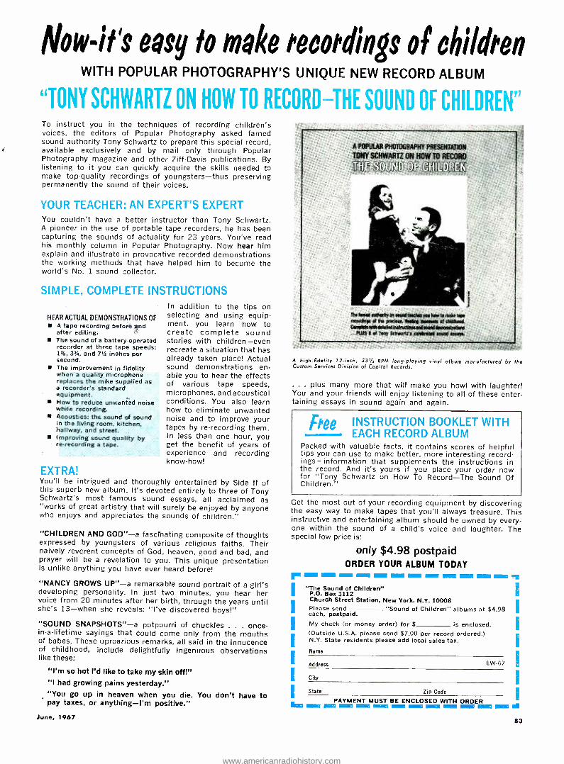
Now -it's easy to make recordings of children WITH POPULAR PHOTOGRAPHY'S UNIQUE NEW RECORD ALBUM
"TONY SCHWARTZ ON HOW TORFCORD -THE SOUND OF CHILDREN" To instruct you in the techniques of recording children's voices, the editors of Popular Photography asked famed sound authority Tony Schwartz to prepare this special record, available exclusively and by mail only through Popular Photography magazine and other Ziff -Davis publications. By listening to it you can quickly acquire the skills needed to make top -quality recordings of youngsters -thus preserving permanently the sound of their voices.
YOUR TEACHER: AN EXPERT'S EXPERT You couldn't have a better instructor than Tony Schwartz. A pioneer in the use of portable tape recorders, he has been capturing the sounds of actuality for 23 years. You've read his monthly column in Popular Photography. Now hear him explain and illustrate in provocative recorded demonstrations the working methods that have helped him to become the world's No. 1 sound collector.
SIMPLE, COMPLETE INSTRUCTIONS
HEAR ACTUAL DEMONSTRATIONS OF A tape recording before and after editing. The sound of a battery -operated recorder at three tape speeds: 13/4r, 314, and 7'h inches per second. The improvement in fidelity when a quality microphone replaces the mike supplied as a recorder's standard equipment. How to reduce unwanted noise while recording. Acoustics: the sound of sound in the living room, kitchen, hallway, and street. Improving sound quality by re- recording a tape.
In addition to the tips on selecting and using equip- ment, you learn how to create complete sound stories with children -even recreate a situation that has already taken place! Actual sound demonstrations en- able you to hear the effects of various tape speeds, microphones, and acoustical conditions. You also learn how to eliminate unwanted noise and to improve your tapes by re- recording them. In less than one hour, you get the benefit of years of experience and recording know -how!
EXTRA! You'll be intrigued and thoroughly entertained by Side II of this superb new album. It's devoted entirely to three of Tony Schwartz's most famous sound essays, all acclaimed as "works of great artistry that will surely be enjoyed by anyone who enjoys and appreciates the sounds of children."
"CHILDREN AND GOD " -a fascinating composite of thoughts expressed by youngsters of various religious faiths. Their naively reverent concepts of God, heaven, good and bad, and prayer will be a revelation to you. This unique presentation is unlike anything you have ever heard before!
"NANCY GROWS UP " -a remarkable sound portrait of a girl's developing personality. In just two minutes, you hear her voice from 20 minutes after her birth, through the years until she's 13 -when she reveals: "I've discovered boys!"
"SOUND SNAPSHOTS " -a potpourri of chuckles . . . once - in-a- lifetime sayings that could come only from the mouths of babes. These uproarious remarks, all said in the innocence of childhood, include delightfully ingenuous observations like these:
"I'm so hot I'd like to take my skin off!" "I had growing pains yesterday." "You go up in heaven when you die. You don't have to pay taxes, or anything -I'm positive."
June, 1967
A POPULAR PHOTOGRAPHY PRESENTATION
TONY SCHWARTZ ON HOW TO RECORD
ME o5
The famed mnivrtty do sound teWes you howls make tope recordings of Me preeieue, Not* moments of childhood Compete vent detailed instnutlonsand sound demons tretbr s
_PUTS pot Tony Schwartz's cekhoted sound estret
A high -fidelity 12 -inch, 331/2 RPM long -playing vinyl album manufactured by the Custom Services Division of Capitol Records.
... plus many more that will make you howl with laughter! You and your friends will enjoy listening to all of these enter- taining essays in sound again and again.
Thee INSTRUCTION BOOKLET WITH EACH RECORD ALBUM
Packed with valuable facts, it contains scores of helpful tips you can use to make better, more interesting record- ings- information that supplements the instructions in the record. And it's yours if you place your order now for "Tony Schwartz on How To Record -The Sound Of Children."
Get the most out of your recording equipment by discovering the easy way to make tapes that you'll always treasure. This instructive and entertaining album should be owned by every- one within the sound of a child's voice and laughter. The special low price is:
only $4.98 postpaid ORDER YOUR ALBUM TODAY
rot I I I
I
I
I
I
1 MOM 11111118 IMMIMI ISM
"The Sound of Children" P.O. Box 3112 Church Street Station, New York, N.Y. 10008 Please send each, postpaid. My check (or money order) for $ is enclosed. (Outside U.S.A. please send $7.00 per record ordered.) N.Y. State residents please add local sales tax.
"Sound of Children" albums at $4.98
Name
Address EW-67
City
State Zip Code
PAYMENT MUST BE ENCLOSED WITH ORDER lll M - - ! - ® ® m - i - i EN
83
www.americanradiohistory.com

WHY DRIVE A LATE
MODEL CAR WITH A
1910 IGNITION
SYSTEM or*
Install tomorrow's ignition system on
your car today!
THE JUDSON
ELECTRONIC MAGNETO Write today for free literature
JVXII SON RESEARCH AND MFG. CO M CONSHOHOCKEN, PENNA.
CIRCLE NO. 106 ON READER SERVICE CARD
NOW... PERFECT COLOR TV
ELIMINATE FM and OTHER INTERFERENCE
With the Sensational
NEW P7IVCO
FM Trap (Blocks Out FM)
Get pure color signals for perfect color reception. Use a Finco Model 3006 to stop interference and block out unwanted signals from FM. Citizens Band. Amateur transmitters, motors. autos, aircraft, and fluorescent lamps. Size: 413" x 2" s ]1st Available at your Finco dealer.
Model 3006 Only $6.25 List
THE FINNEY COMPANY 34 W. Interstate St. Dept. 410
Bedford, Ohio 44014
FINCO ANTENNAS CAPTURE THE RAINBOW"
CIRCLE NO. 91 ON READER SERVICE CARD 84
EW Lab Tested (Cuntinut'Il frotn page 16)
numbers of listeners whose spacial or financial resources were limited.
Despite their relative compactness, most "bookshelf" speakers were too large and heavy for mounting on real bookshelves. Over the years, many manufacturers have attacked the prob- lem of creating a small, light, and in- expensive speaker system with wide - range, low -distortion response. There have been a few successful designs, and many more which are best forgotten.
The new Jen.Srn X -40 and X -45 speaker systems are recent additions to what might be called true bookshelf systems -and they deliver a caliber of sound which belies their size and price. Their oiled walnut enclosures measure 101,2 "x19' /2 "x9 "or slightly over one cubic foot, and their weight of about 20 pounds will not overtax any shelf capable of supporting books. The X -40 and X -45 are identical except for their high -frequency drivers.
Frequencies from 30 to 2000 Hz are radiated by an 8 -inch long -travel cone woofer with a resonant frequency of 35 Hz. Above 2000 Hz, the X -40 has a 3 -inch direct -radiator speaker, while the X -45 uses a horn -loaded compression - type driver. Both systems are rated at 8 ohms, with a power handling capac- ity of 25 watts and a useful frequency range of 30 to 16,000 Hz. On the rear of the enclosure is a level adjustment for the high- frequency speaker.
We tested the X -40 and X -45 under identical conditions, simulating book- shelf mounting. The microphone re- sponse at eight points in the room were averaged to obtain a composite response curve. Although the two speakers llave identical woofers, we found the X -40 to have somewhat more response be- low 100 Hz. Ignoring the small peaks at 40 and 60 Hz, which are properties of the test room, both speakers llave all over -all response of --5 dB from 30 to over 13,000 Hz, and are down only
lo
15
slightly at 15,000 Hz, which is the up- per limit of our mike's calibration.
The X -40 has its most uniform re- sponse with the tweeter level at maxi- mum, while the more efficient high - frequency speaker of the X -45 shows a rise of about 8 dB at 10,000 Hz under these conditions. Both speakers had low distortion at low frequencies. The X -40 had about half as much distortion be- low 60 Hz as the X -45, which is probably clue to normal production tolerances. It also had somewhat less efficiency than the X -45.
Both speakers have excellent tone - burst response over their entire fre- quency range. Over -all, we would rate their transient response as good as that of any dynamic speaker we have tested, including some costing several times the price of the Jensen speakers. At no time slid we find any evidence of pro- longed ringing, breakup, or spurious outputs.
In. listening tests, we found that the X -40 sounded most pleasing with maxi - mum tweeter level, which corresponds to the flattest measured response. It was necessary to turn down the tweeter level of the more efficient X -45 horn driver considerably to match the sound of the X -40, after which they were in- distinguishable from each other. The cone radiator of the X -40, however, has a distinctly better high- frequency dis- persion than the X -45's horn, with vir- tually no audible beaming of highs.
Both speakers have an effortless, nat- ural sound which one rarely finds in speakers of much greater size and price. Although their bass output does not match that of some larger and cost- lier systems, the listener is never aware he is listening to a one- cubic -foot en- closure. Either speaker can radiate a solid, relatively undistorted 30 -Hz. fun- damental.
The Jensen X -40 sells for $57 and the X -45 for $63. Anyone who doubts that speakers in that price and size bracket can produce true high- fidelity sound owes it to himself to hear one of these speakers and be convinced.
PEAKS CAUSED BY ROOM RESONANCES JENSEN X45 SPEAKER SYSTEM -FREQUENCY RESPONSE- -
I
.l t- + 1 + ' - t _ CORRECTED FOR ROOM RESPONSE BELOW I000Hr-
AVERAGE OF e 1NDOOR RUNS
TONE BUv"
20 SO 100 200
BURST
500 1k 2 5k 10k 20k
-
1 t
.. I
l '
H
(ll I III 1 ;
I I
FIRM i ii,^w1
u11IH ,. i I-WATT INPUT. liq
I
1V I
Ìn11111n1u
A v ̂-..: i
R¢® "illiiii ton= siri FREQUENCY -Hz
ELECTRONICS WORLD
www.americanradiohistory.com

DELUXE LEATHERFLEX- COVERED EDITIONS AVAILABLE Here is a complete selection of annuals, yearbooks, directories and handbooks available in Deluxe Leatherflex- covered editions from the world's largest publisher of special interest magazines. These are complete editions (including the original covers) which are bound in rugged leatherflex to provide long-time pro-
tection and keep them looking like new even after repeated use. The softly textured leatherflex, gold embossed for the look of elegance, makes them handsome additions to your permanent reference library. Take a moment to review the titles below. You're sure to find many of your favorites. $3.00 each.
ELECTRONIC
ERPERIMENTER'S ,.
PHOTOGRAPHY ANNUAL A selection of the World's finest
photographs compiled by the editors of Popular Photography.
212 Pages - 24 in full color.
1966..._._... ... .... #1 1965 #2q'
1964 #3
PHOTOGRAPHY DIRECTORY Worlds most complete photographic buying guide. 1966_ ............. #22
ELECTRONIC EXPERIMENTER'S
HANDBOOK Many challenging projects for the
electronics hobbyist.
1966 Spring Edition
#36 1965
Fall Edition #9
CAR & DRIVER YEARBOOK
A complete buyers guide covering virtually every
car available in the United States ... Road tests ...
Technical specifications .. Accessories and
performance equipment buying guide ...
Guide to racing with action -packed photos.
1966 #15
,u.,,a 1966TAPERECORDER FLYING' '
ANNUAL & pibts'guida
INVITATION TO PHOTOGRAPHY
INVITATION TO PHOTOGRAPHY
A unique 116 page guide to better. picture taking by
the Editors of Popular Photography. Basic down to -earth advice that helps
you eliminate costly trial and error, time-consuming guess work 20 complete, fact -and photo
packed articles in all. 1966 ................ #35
TAPE RECORDER ANNUAL Everything you need to know about tape -ecording including a complete directory of mono and stereo recorders. 1966 .................#30
COMMUNICATIONS HANDBOOK
The most complete and upto date guide to the exciting world
of specialized radio communications.
1966 .................. #18
ELECTRONICS INSTALLATION AND SERVICING HANDBOOK The only complete guide for servicemen and hobbyists to every major phase of consumer electronics servicing. 1966 #32
FLYING ANNUAL
The most valuable aviation yearbook ever compiled . .. Pilot
reports ... Aircraft directory .. How to buy a used airplane .
Navcom directory ... Learn to fly section.
1966. ........# 27
1965 .............. #28
FLYING ANNUAL.,...., ,....
STEREO /Hi Fi
DIRECTORY Complete buyers
guide for virtually every Hi -Fi component
manufactured. 1966 .................. #29
POLAROID LAND PHOTOGRAPHY Complete guide and only comprehensive and up -to -date handbook on Polaroid Land Photography. 1966 .._ __..._.# 24
FLYING TRAVELGUIDE Here's the first really useful guide to flying vacations. Everything you
need to know about: lodgings, restaurants, resorts, sightseeing,
recreation, sports activities, airport facilities,
childrens fun, price information.
and much more. SKIING
1966...... #34 INTERNATIONAL
YEARBOOK A luxuriously illustrated
compendium of 1965's important events ... A timely forecast of the excitement -packed
1966 season -by the editors of Skiing Magazine.
STEM RhFl:"' DIRECTORY _..
I I f., i.
1
L,
Deluxe Leatherflex- covered Editions are $3.00 each, postpaid ($3.75 for orders out- side of U.S.A.). The annuals listed above are also available in regular editions at $1.25 each plus 15c per copy for shipping and handling ($1.75 for orders outside U.S.A.). To order your copies, check the appropriate box and circle the numbers of the annuals you wish to receive on the coupon to the right.
* Available in Deluxe Edition only.
Ziff -Davis Publishing Co., Dept. SD One Park Ave., New York, N. Y. 10016
I am enclosing $ ID Send me the Deluxe Leatherflex- covered editions circled below at
$3.00 each, postpaid ($3.75 per copy for orders outside U.S.A.). Send me the regular editions circled below at $1.25 each plus 15c shipping and handling ($1.75 per copy for orders outside U.S.A.)
1 2 3 9 15 18 22 24 26 27 28 29 30 32 34 35 36
Name
Address
City State 7ip Code PAYMENT MUST BE ENCLOSED WITH ORDER
(PISE EW-67
June, 1967 85
www.americanradiohistory.com

NE\ , PRODUCTS & LITERATUKE
Additional information un the items covered in this section is available from the manufacturers. Each item is identified by a code number. To obtain further details, fill in cou- pon on the Reader Service Card.
COMPONENTS TOOLS TEST EQUIPMENT HI -FI AUDIO CB HAM COMMUNICATIONS
DUAL- PURPOSE PENCIL IRON The dual -purpose pencil soldering iron being
marketed as the "Un:line Mark VII" consists of three basic components: a combined handle with a three -conductor flexible cord set, NEMA plug, and pneumatic section; a long -life heat cartridge (mailable in 211, 311, -ill, and 511 watt
sizes); and a ruggedized tip (in 33 configu- rations in six styles of 0.1)62 o.d. x 0.023 i.d. tip) specifically designed for matrix soldering and micronuhdule assembly. Also included are eight styles of the 0.125 o.d. x 11.035 i.d. tips as well as seven variations of the 11.187 o.d. x 11.1)55 i.d. All of the tips arc available in chisel, point, spade, pyramid, Hat -faced, and general - purpose shapes.
The unit comes with a white porcelain "Bra- zier Consolette" which incorporates two waste solder depositories which also serve the purpose of keeping the iron tip tinned.
Since all components in the iron are inter- changeable, users can select and combine fea- tures as required for a specific soldering job. Details on the full line and the various con- ] nts will he supplied on request. Vanguard
Circle No. 1 on Reader Service Card
PLASTIC -PACKAGED IC'S Two new integrated circuits, designed for use
in telemetry. data -processing, instrumentation, and communications equipment, have just been introduced as the CA3029 and CA30311.
These monolithic silicon operational ampli- fiers are housed in a 14 -lead dual in -line plas- tic package, permitting simpler insertion, high- er packaging densities, and reduced cost. They offer open -loop voltage gains of 611 dB and 711
dB typical, common -mode rejection ratios of 94 dB and 103 dB typical, and have maximum cutput- voltage swings of 6.75 volts peak -to -peak and 14 volts peak -to -peak typical. RCA Elec- tronic Components
Circle No. 126 on Reader Service Card
CURRENT -LIMITER DIODES A series of nine current -limiter field -effect
diodes for constant current biasing of transis- tors, FET's, differential amplifiers, and zener reference diodes has just been announced. These new units are useful in place of the logic pull -up resistor for high -speed switching, as a high- impedance load with low supply voltage, and as a current -limiting protecting device. Other applications include linear time -base cir- cuits and d.c. current supplies.
The CL2010 series offers standard EIA cur- rent values from 220 pit to 4.7 mA. The first three digits of the number indicate rated cur-
86
rent in microamperes while the fourth digit in- dicates tolerance; e.g., CL1521) is a 1500 -pA. 211 % -tolerance diode. The units are housed in a miniaturized plastic package. Siliconix
Circle No. 127 on Reader Service Card
VIBRATING MEMBRANE CAPACITOR The Type XL79011 vibrating membrane ca-
pac:tor is designed as a transducer for extra - sensitive current measurements. When employ- ed in an electrometer, the XL79011 has mea- sured currents as weak as 51111 electrons per second (8 x 10' ampere). The unit can he used in such instruments as dosimeters, gas chromatography current detectors, picoammeters, pH meters, and transducer monitors.
Driven by a high- frequency electric field and housed in an evacuated glass envelope, the new sensor offers input impedance greater than IO" ohms and temperature dependence of only 15 pV "C. The high- frequency, electric-field drive effectively isolates the drive frequency from the signal output and greatly simplifies design of the drive oscillator, according to the company. Amperex
Circle No. 128 on Reader Service Card
COLOR -TV SWEEP -CIRCUIT COILS Exact replacement sweep -circuit coils for the
color -TV sets produced by more than 25 manu- facturers are now available.
The focus, convergence, and sweep -circuit coils are directly interchangeable with original coils in sets manufactured by such firms as
RCA, Philco, Westinghouse, Motorola, and Mentz. Full details on the entire line will be supplied on request. 1.W. Miller
Circle No. 2 on Reader Service Card
MINIATURE COMPONENTS Two new miniature electronic components,
the Model 4211 microtransformer and the Model 4221 microinductor have just been in- troduced, both designed for welded module and hybrid circuit applications.
The new models measure only '8" x ! n" x 58" and weigh a maximum of 11.15 gram. Frequency range is 2000 to 500,000 Hz while the operating temperature range is -55 °C to +105°C. Both models meet or exceed environmental requirements of MIL -T -27, grade 5.
The microtransformer has a primary and secondary impedance range of 10 to 10,001) ohms while the inductance range of the Model 4221 is from 0.1 to 3.5 henry at 1 kHz, 0.1 volt r.m.s. Bourns Trimpot
Circle No. 129 on Reader Service Card
TRANSISTOR TRANSFORMERS A new series of ultra nainiature transistor
transformers is now on the market and avail-
able for immediate delivery. The DO -T201) series features straight pin terminals, making them suitable for printed- circuit applications. They are metal encased and ruggedized. Max- imum diameter is 11.351)" and maximum height is °'tie ". The mounting base has a key- bearing moisture -barrier offset of 0.035 ". Leads are é" long and of 0,016" Dumet wire, gold
plated. The leads are weldable or solderable. Units in the series have primary impedances
from 11)1111 to 21)0,000 ohms, d.c. in the pri- mary from 0 to 3 mA, secondary impedances of 511 to 12,1)1)1) ohms, and operating levels of 25 to 11111 milliwatts. Details on the full line are available on request. UTC
Circle No. 130 on Reader Service Card
PUSH- BUTTONS FOR COMPUTERS The 913 series of momentary contact push-
button switches has been designed for use in dry circuits or with low currents at higher voltages. The switches mount in a 'x" clearance hole on !';" centers. Available for s.p.s.t. dou- ble- break, normally open or normally closed; s.p.d.t., double-break. two- circuit (one n.o., one n.c.) operation, this series can be obtained il- luminated or non -illuminated. Lighted switches use permanently mounted T -2 neon lamps with or without the necessary current -limiting re- sistor.
Switch ratings are 0.1 amp, 125 V a.c.; 0.1 amp, 311 V d.c. (non -inductive); operating force is 10 ounces (approximately) and button travel is ¡ ;t "- Life rating is 1,000,111111 operations. Dialight
Circle No. 131 on Reader Service Card
NICKEL- CADMIUM BATTERIES A new line of sealed, rechargeable nickel-
cadmium batteries and power packs has just been announced. The batteries, available in a variety of sizes, shapes, and capacities, will be built to customers' specifications to provide high cell -to -cell uniformity.
Applications of these new power sources in- clude aircraft emergency power, military and industrial instruments and systems, telecommu- nications equipment, and cordless power tools and appliances. Texas Instruments
Circle No. 132 on Reader Service Card
LABORATORY STOP CLOCKS Two new compact, portable laboratory stop
clocks specifically designed for maximum ver- satility have been introduced as the K15140 and the KI5150.
The K15140 is calibrated in seconds and hundreds, with a totalizer scale of 0 -611 seconds
ELECTRONICS WORLD
www.americanradiohistory.com
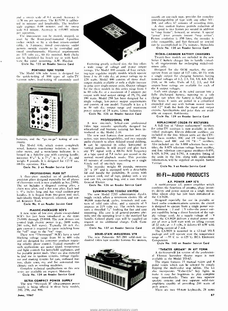
and a sweep scale Of 0 -1 second. Accuracy is
±211 ms per operation. The KI51511 is calibra- ted in minutes and hundredths. The totalizer scale registers 0 -60 minutes and the sweep scale 0-1 minute. Accuracy is ±0.005 minute per operation.
The instruments can be started, stopped, or reset by the front -panel- mounted 3- position rocker switch or by a six -foot remote- control cable. A 3- ampere, timed convenience outlet permits outside circuits to be controlled and tinted simultaneously. Electrical requirements are 115 volts a.c., 60 Hz nominal. Both clocks can be furnished for bench use or with hard- ware for panel mounting. A.W. Haydon
Circle No. 133 on Reader Service Card
PORTABLE TUBE TESTER The Model 636 tube tester is designed for
the quick -testing of 800 types of radio -TV vacuum tubes, load- testing of commonly used
baitcrirs, anil the "go no -go- toting of con- tinuity.
The Model 636, which comes completely wired, features transformer isolation, a three - color meter, and a neon -lamp indicator. It is
housed in a Bakelite case with carrying handle, measures 85 " h. x 71/2" w. x 3! 8" d., and weighs 4 pounds. It is designed for 117 -V a.c., 60 -Hz operation. Eico
Circle No. 3 on Reader Service Card
PROFESSIONAL PLIER SET
A three -piece matched set of professional, precision pliers designed especially for all phases of electronics work is now available as No. 23091. The set includes a diagonal cutting plier, a
chain nose plier, and a flat nose plier. Each tool is 41/2 inches long and has vinyl cushion -grip handles. It is forged from fine -grain tool steel, individually fitted, tempered, adjusted, and test- ed. Kraemer Tools
Circle No. 4 on Reader Service Card
PLASTIC- PACKAGED SCR'S A new series of low -cost, plastic -encapsulated
SCR's has just been introduced as the types 2N4441 through 2N4444. The new devices can control high electric power (e.g., 2600 watts, 240 volts, full wave). Typically 10 mA d.c. gate current is required to cause switching from the "off" stage to the "on" stage.
These new "Thermopad" SCR's have a rated Mocking voltage range from 5(1 to 600 volts and are designed for consumer products requir- ing reliable phase control. Typical examples of such applications are motor speed, temperature and light controls for household appliances, and for portable power tools. They are also expected to find use in ignition systems, voltage regula- tor and starting systems for cars, outboard mo- tors, chain saws, etc. and for automated ma- chinery such as vending machines.
Complete technical specifications on this new series are available on request. Motorola
Circle No. 134 on Reader Service Card
ULTRA -COMPACT POWER SUPPLY The new "Micropak II" ultra -compact power
supply is being offered in three basic models, 200, 250, and 400.
Featuring greatly reduced size, the line offers a wide range of voltage and power output ratings. The Model 400 consists of four switch- ing -type regulator supply models which operate from 3 to 30 volts d.c. at power ratings up to 120 watts. Model 400 consists of three dual -
output models available at only a slight increase in price over single -output units. Output voltages for the three models in this series range from 3
to 40 volts d.c. at a maximum of 2 amperes per output with total output ratings of 35, 70, and 100 watts, Model 250 has been designed for a
single voltage, low -power output requirements and consists of one model. Typically it has a 3
to 30 volt d.c. output range and maximum power output of 24 watts. Litton Industries
Circle No. 135 on Reader Service Card
PROFESSIONAL VTR A new one -inch, helical -scan professional
video tape recorder specifically designed for educational and business training has been in- troduced as the Model 2 -30.
The new unit features slow motion and stop action, tape interchangeability, and two separate audio channels to allow delayed sound dubbing. It can be operated in either horizontal or vertical position. It will record and play back any TV signal with a 60 -Hz field frequency at a tape speed of 7.8 inches per second in the normal record 'playback mode. This provides 63 minutes of continuous recording on a single 8 -inch reel of one -inch tape.
The recorder weighs 88 pounds, measures 26" x 18" and is equipped with a detachable lid and handle for portability. It comes with a power cord, reel of tape, pickup reel, a use
and care kit, carrying bag, and a user manual. General Electric
Circle No. 136 on Reader Service Card
SUBMINIATURE TOGGLE SWITCH The new Model 7213 subminiature d.p.d.t.
toggle switch offers a minimum electric life of 40,000 make -break cycles, terminals and con- tacts of solid coin silver, and a capacity of 5
amperes at 115 volts a.c. The switch incorpo- rates a threaded 1,4" bushing for fast and easy mounting. The case is of general -purpose phe- nolic and the operating lever is the standard bat handle. Colored plastic caps will be supplied on request at no additional charge. C&K Com- ponents
Circle No. 137 on Reader Service Card
SOLID -STATE INDUSTRIAL VTR The new Panasonic NV -204 solid -state in-
dustrial video tape recorder features five motors,
records on one -inch tape, provides for complete interchangeability of tape with any other NV- 204, and offers 67 minutes of recording time.
A slow motion feature permits reduction of tape speed to two frames per second in addition to "stop frame ", forward, or reverse. A special "pause" lever permits instant "stop action ". Picture resolution is 350 lines, the recorder is
color compatible, and fast forward or rewind can be accomplished in 23/4 minutes. Matsushita
Circle No. 138 on Reader Service Card
NICKEL -CADMIUM BATTERY CHARGERS Twenty -four models are included in the new
Series C battery charger line to handle virtual- ly all requirements for recharging nickel -cad- mium cells.
Designed for the OEM market, the units operate from an input of 117 volts, 60 Hz with a single output for charging batteries having nominal voltages of 1.2, 2.4, 3.6, 4.8, 6.0, 12.0, 24.0, or 36 volts. Units of 1.2, 2.3, and 4.0 ampere -hour ratings are available for each of the 8 output voltages.
Each unit charges at its rated current into a
fully discharged battery, tapering to a safe charge rate when the battery is fully charged. The Series C units are potted in a cylindrical enameled steel cup with bottom mount inserts and 12" leads for both the input and output circuits. Specifications and price data are avail- able on request. Berkleonics
Circle No. 139 on Reader Service Card
REPLACEMENT COLOR -TV RECTIFIERS A full line of "direct replacement" rectifiers
for color -TV receivers is now available in indi- vidual packages. Eleven different rectifiers are included in the line. Silicon units are the CTV- 650 focus rectifier, 80C and F8 voltage boost rectifiers, and 60C and F6 `B +" rectifiers. Also included are the S -880 selenium focus rec- tifier, the S -879 selenium voltage boost rectifier, and four selenium convergence rectifiers -S -855, S -420, S -798, and S -781. A complete listing of the units in the line, along with replacement information, will be supplied on request. Sarkes Tarzian
Circle No. 5 on Reader Service Card
HI -FI -AUDIO PRODUCTS
A.F. POWER AMP IC'S A multi-purpose a.f. power amplifier which
combines the functions of preamp, phase invert- er, driver and power output on a single mono- lithic silicon chip has just been introduced as
the CA3020. Designed especially for use in portable or
fixed audio communications systems, the circuit is designed to operate from a single power sup- ply between +3 and +9 volts -the power out- put capability being a direct function of the sup- ply voltage used. At a supply voltage of +9 volts, the CA3020 delivers a typical power out- put of over a half watt with an idling carrent of 22 mA; at +3 volts, it delivers 65 mW with an idling current of 7 mA.
The CA3020 is mounted in a 12 -lead TO -5 package and will operate over the temperature range of -55 °C to +125 °C. RCA Electronic Components
Circle No. 140 on Reader Service Card
"THEATER ORGAN" IN KIT FORM A do- it- yourself kit version of the profession-
al Thomas horseshoe theater organ is now available as the Model TO -67.
The organ features 15 manual voices and 4 pedal voices which can be selected by simply flipping the multi -color stop tablets. The kit also incorporates "Color -Glo" key lights to make it easy for beginners to play complete songs immediately. There are two separate speaker systems and two separate solid -state amplifiers capable of providing 200 watts of peak power.
There are two 44 -note keyboards, 28 notes
June, 1967 87
www.americanradiohistory.com
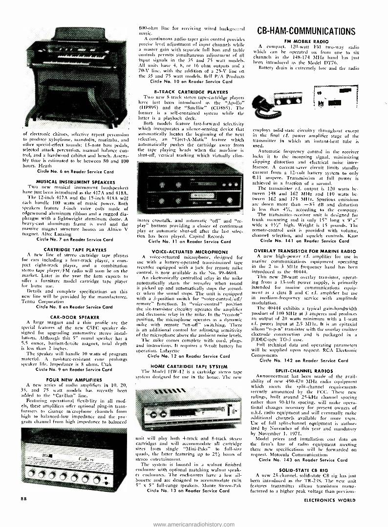
of electronic chimes, selective repeat percussion to produce xylophone, mandolin, marimba, and other special- effect sounds; 13 -note bass pedals, selected attack percussion, manual balance con- trol, and a hardwood cabinet and bench. Assem- bly time is estimated to be between 80 and 100 hours. Heath
Circle No. 6 on Reader Service Card
MUSICAL INSTRUMENT SPEAKERS Two new musical instrument loudspeakers
have just been introduced as the 417A and 418A. The 12 -inch 417A and the 15 -inch 418A will
each handle 100 watts of music power. Both speakers feature 3 -inch voice coils made of edgewound aluminum ribbon and a rugged dia- phragm with a lightweight aluminum dome. A heavy -cast aluminum frame is used and the massive magnet structure houses an Alnico V magnet. Altec Lansing
Circle No. 7 on Reader Service Card
CARTRIDGE TAPE PLAYERS A new line of stereo cartridge tape players
for cars including a four -track player, a com- pact eight -track player, and a combination stereo tape player /FM radio will soon be on the market. Later in the year the firm expects to offer a furniture model cartridge tape player for home use.
Details and complete specifications on this new line will he provided by the manufacturer. Tcnna Corporation
Circle No. 8 on Reader Service Card
CAR -DOOR SPEAKER A large magnet and a thin profile are the
special features of the new CSFC speaker de- signed for upgrading automotive stereo instal- lations. Although this 5" round speaker has a 5.5 ounce, barium- ferrite magnet, total depth is less than 2 inches.
The speaker will handle 10 watts of program material. A moisture- resistant cone prolongs speaker life. Impedance is 8 ohms. Utah
Circle No. 9 on Reader Service Card
FOUR NEW AMPLIFIERS A new series of audio amplifiers in 10, 20,
35, and 75 watt models has recently been added to the "Carillon" line.
Featuring operational flexibility in all mod- els, these amplifiers offer optional plug -in trans- formers to change microphone channels from high to balanced -low impedance and the pro- gram channel from high impedance to balanced
88
600 -ohm line for receiving wired background music.
A continuous audio -taper gain control provides precise level adjustment of input channels while a master gain with separate full bass and treble controls permits simultaneous adjustment of all input signals in the 35 and 75 watt models. All units have 4, 8, or 16 ohm outputs and a 70 -V line, with the addition of a 25 -V line on the 35 and 75 watt models. Bell P/A Products
Circle No. 10 on Reader Service Card
8 -TRACK CARTRIDGE PLAYERS Two new 8 -track stereo tape -cartridge players
have just been introduced as the "Apollo" (HP895) and the "Satellite" (CD885). The former is a self -contained system while the latter is a playback deck.
Both models feature fast -forward selectivity which incorporates a silence -sensing device that automatically locates the beginning of the next selection, an "Eject -A- Matic" feature which automatically pushes the cartridge away from the tape playing heads when the machine is shut -off, vertical tracking which virtually dim- __
inates crosstalk, and automatic "off" and "re- play" buttons providing a choice of continuous play or automatic shut -off after the last selec- tion has been played. Capitol Records
Circle No. 11 on Reader Service Card
VOICE- ACTUATED MICROPHONE A voice -actuated microphone, designed for
use with a battery -operated transistorized tape recorder equipped with a jack for remote mike control, is now available as the No. 99 -4604.
An electronically controlled relay in the mike automatically starts the recorder when sound is picked up and automatically stops the record- er when the sound stops. The unit is equipped with a 3- position switch for "voice -control /off/ remote" functions. In "voice- control" position the six -transistor circuitry operates the amplifier and electronic relay in the mike. In the "remote" position, the microphone operates as a dynamic mike with remote "on -off" switching. There is an additional control for adjusting sensitivity of the microphone above the ambient noise levels.
The mike comes complete with cord, plugs, and instructions. It requires a 9 -volt battery for operation. Lafayette
Circle No. 12 on Reader Service Card
HOME CARTRIDGE TAPE SYSTEM The Model 1-1W -12 is a cartridge stereo tape
system designed for use in the home. The new
unit will play both 4 -track and 8 -track stereo cartridges and will accommodate all cartridge sizes from single "Mini -Paks" to full -size quads, the latter featuring up to 21/2 hours of stereo entertainment.
The system is housed in a walnut finished enclosure with optional matching walnut speak- er enclosures. The enclosurers have a low sil- houette and are designed to accommodate twin 3" x 5" full -range speakers. Muntz Stereo -Pak
Circle No. 13 on Reader Service Card
CB- HAM -COMMUNICATIONS FM MOBILE RADIO
A compact, 120 -watt FM two -way radio which can be operated on from one to six channels in the 148 -174 MHz band has just been introduced as the Model DT76.
Battery drain is extremely low and the radio
employs solid -state circuitry throughout except in the final r.f. power amplifier stage of the transmitter in which an instant -heat tube is used.
Automatic frequency control in the receiver locks it to the incoming signal, minimizing clipping distortion and electrical noise inter- ference. A current -saver circuit limits standby current from a 12 -volt battery system to only 0.11 ampere. Transmission at full power is achieved in a fraction of a second.
The transmitter r.f. output is 120 watts be- tween 148 and 162 MHz and 110 watts be- tween 162 and 174 MHz. Spurious emissions are down more than -85 dB and distortion is less than 4 %, according to the company.
The transmitter -receiver unit is designed for trunk mounting and is only 15" long x 9' x" wide x 41/2" high. Weight is 15 pounds. The remote -control unit is provided with volume, channel selection, and squelch controls. Kaar
Circle No. 141 on Reader Service Card
OVERLAY TRANSISTOR FOR MARINE RADIO A new high -power r.f. amplifier for use in
marine communications equipment operating in the 2 to 3 MHz frequency band has been introduced as the 40444.
This new 20 -watt overlay transistor, operat- ing from a 13 -volt power supply, is primarily intended for marine communications equip- ment as a class B and C r.f. amplifier for use in medium- frequency service with amplitude modulation.
The 40444 exhibits a typical gain- bandwidth product of 100 MHz at 3 amperes and produces an output of 20 watts minimum with a 1 -watt r.f. power input at 2.5 MHz. It is an epitaxial silicon "n -p -n" transistor with the overlay emitter electrode construction and is packaged in a JEDEC -type TO -3 case.
Full technical data and operating parameters will be supplied upon request. RCA Electronic Components
Circle No. 142 on Reader Service Card
SPLIT- CHANNEL RADIOS Announcement has been made of the avail-
ability of new 450 -470 MHz radio equipment which meets the split -channel requirements recently announced by the FCC. These new rulings, built around 25 -kHz channel spacing rather than 50 -kHz spacing, will make opera- tional changes necessary for present owners of u.h.f. radio equipment and will eventually make additional channels available for more users. Use of full split- channel equipment is author- ized by November of this year and mandatory by November 1, 1971.
Model prices and installation cost data on the firm's line of radio equipment meeting these new specifications will be forwarded on request. Motorola Communications
Circle No. 143 on Reader Service Card
SOLID -STATE CB RIG A new 23- channel, solid -state CB rig has just
been introduced as the TR -23S. The new unit features transmitter silicon transistors manu- factured to a higher peak voltage than previous.
ELECTRONICS WORLD
www.americanradiohistory.com

ly available, plus new zener diode protection. The unit measures 51/4" w. x 61/4" d. x 17 /s" h. It comes complete with microphone, illu- minated "S" meter, illuminated channel selec- tor, and d.c. cord. Crystals are supplied for all 23 channels. Courier
Circle No. 14 on Reader Service Card
COAXIAL SWITCH FOR HAM /CB A new single -pole, two -position coaxial switch
designed for either ham or CB applications is now available as the Model 2 P. The switch has a current -carrying capacity of 9 amperes and a power- carrying capacity of 1000 watts. It may be inserted into the system without mea- surable insertion loss or impedance problems, according to the manufacturer.
The switch can be installed in line and is
designed for panel mounting, if desired. The average initial contact resistance on the switch is 5 milliohms. It has a power rating of 1 kW AM or 2 kW p.e.p. for SSB. Clips and rotor contacts are silver -plated brass and the switch is insulated with electrical -grade laminated phenolic which provides protection against voltage breakdown of critical parts to 1000 volts r.m.s. Gold Line Connector
Circle No. 15 on Reader Service Card
COMMUNICATIONS RECEIVER The SB -301 ham -band communications re-
ceiver is an improved version of the firm's SB -300 kit receiver. It offers increased sensi- tivity, full RTTY provisions with an RTTY position on the mode switch, 15 to 15.5 MHz coverage for W W V reception, built -in switch-
selected automatic noise limiter, and front - panel switching for control of the optional b- and 2 -meter converters.
The receiver provides 80 through 10 meter ham -band coverage for receiving AM, c.w., upper and lower sideband SSB, and RTTY. It has a crystal -controlled front -end and a pre - assembled and calibrated linear master oscil- lator for linear tuning and maximum stability. It is capable of transceiver operation when used as a companion to the SB -401 transmitter. There is a matching speaker kit. SB -600, avail- able for use with the receiver. Heath
Circle No. 16 on Reader Service Card
CB TRANSCEIVER FOR MARINE USE The new "Ranger" transceiver has been
especially designed to provide CB communica- tions between boats or between a boat and shore.
The 11- channel, all- transistor model features heavy welded steel chassis, spray- coated for protection from moisture and salt elements, and a splash -proof speaker. The circuit board is constructed of epoxy glass for long life while the circuitry includes a Collins mechan- ical filter for maximum selectivity. A TO -3 power transistor provides 100% duty -cycle capability.
The operator can use plug -in type crystals
for any 11 of the 23 CB channels. For mobile operation, 12 volts d.c. is required or the unit may be operated as a base station with the optional 120 -volt, 60 -Hz power supply. There is provision for an external speaker or hailer facility.
The transceiver measures 27/8" x 63/8" x 71:h1.". Regency
Circle No. 17 on Reader Service Card
PRIVATE TONE CALLER The "Priva -Com III" transistorized private
tone caller features ceramic and resonant tun- ing fork circuitry instead of conventional reed relays. It is designed to be used with 12 -volt solid -state CB transceivers. It features 9 -tran- sistor, 2 -diode circuitry with simple -to- operate
IM LAFAYE, TE
push button switches for standby, normal, call, and reset. There is a volume control and in- dicator light.
The unit, which measures 1'ír" h. x 4" w. x 53/4" d. is supplied with a mounting bracket, two plug -in tuning fork filters, and connecting cable with plug for the firm's HB -500A, HB- 555, HB -525A, HB -600, and HE -20T CB transceivers. A model for use with tube -type transceivers is also available. Lafayette
Circle No. 18 on Reader Service Card
CB TRANSCEIVER /P.A. SYSTEM A new five -watt, solid -state CB transceiver/
p.a. system with the accent on mobile operating convenience and safety has been introduced as the Model CB -21.
The new unit contains a 17- transistor, 8- channel transceiver with a dual- conversion re- ceiver. Features which provide increased con- venience and safety include concentric volume and squelch controls, illuminated channel selec- tor, and an easily operated rocker switch which converts the CB -21 into a p.a. system with 4 watts of low- distortion audio output.
The CB -21 measures 2'1 s" high x 6" wide x 8" deep and weighs approximately 51/2 pounds. It comes complete with channel -11 crystals for transmit and receive. An optional power supply for 110 -125 volt a.c. operation is available. Hallicrafters
Circle No. 19 on Reader Service Card
SHORT -WAVE PORTABLE The new "Globepacer" short -wave portable
receiver is all- solid -state and features coverage of 11 bands, including AM and FM broadcast bands as well as long -wave and short -wave services.
The receiver has a horizontal slide -rule dial with rotating cylindrical dial scale for precise and accurate tuning. It features tone control and a.f.c. to eliminate drift on FM. A large ferrite bar antenna is used for the long- and
medium -wave bands while a multi -section whip is provided for short -wave and FM reception. The two -way speaker system consists of a 4" woofer and a 11/ " tweeter. There are separate jacks for external antenna, earphone, a.c. (with optional adapter) , speaker, and phono. The unit measures 13" x 8" x 5" and requires six "C" cells for operation. Lafayette
Circle No. 20 on Reader Service Card
MARINE RADIOTELEPHONE A new generation marine radiotelephone
operates in the v.h.f. band with the static -free clarity of FM radio, according to the manu- facturer. The new set is designed to transmit at full power with an antenna as short as 20 inches and needs no ground plate attached to the boat's hull.
The new 12- channel two -way radio can be used to talk with other boats, call the Coast Guard for assistance, or talk to anyone ashore through the marine operator. Range of the new radiotelephone is up to 40 -50 miles. Ray- theon
Circle No. 21 on Reader Service Card
MANUFACTURERS' LITERATURE VOLTAGE REGULATORS
A new 12 -page illustrated brochure describing the "Solatron" line of line- voltage regulators is
now available. Complete electrical and mechan- ical specifications for single -phase, three -phase delta, and three -phase wye regulators are out- lined in the booklet.
In addition, the publication (VR -201) de- scribes a number of housings for the instru- ments as well as auxiliary harmonic filters. Sola
Circle No. 144 on Reader Service Card
TEST EQUIPMENT A new 16 -page 1967 test equipment brochure
covering a complete line of v.o.m.'s and adap- ters, v.t.v.m.'s, general -purpose microtesters, oscilloscopes, temperature- measuring instruments, and accessories has been published. Featured in the booklet is the company's newest addition, the Model 160 palm -sized v.o.m. Simpson
Circle No. 22 on Reader Service Card
SPEAKER CATALOGUE A new 24 -page illustrated booklet covering a
full line of high -fidelity sound products has been issued. Described in the brochure are full -size and bookshelf loudspeaker systems; unitary, dual -cone, and coaxial loudspeakers; speaker system components including woofers, tweeters, crossover networks, and balance controls; and three -way loudspeaker systems kits.
Featured in the catalogue (No. 165 -M) are sections on designing speaker enclosures and choosing loudspeakers. Jensen
Circle No. 23 on Reader Service Card
ELECTRONIC COMPONENTS A full line of composition- and wircwound-
element potentiometers, field- assembled controls, power rheostats, resistors, and miscellaneous components is described and illustrated in a new 32 -page 1967 catalogue. Complete technical specifications and dimensional drawings are provided for all devices listed. Clarostat
Circle No. 145 on Reader Service Card
MAGNETIC SHIELDING A new 36 -page illustrated design handbook
(No. B -9236) covering all aspects of magnetic shielding in low -frequency applications is now available. Topics discussed include design pa- rameters; choice and comparison of materials; cylindrical, conical, multiple (nested), and wrap- around shields; heat treatment; and shield evaluation. Westinghouse
Circle No. 146 on Reader Service Card
NICKEL -CADMIUM BATTERIES Introduced in 10 -page illustrated brochure is
the company's new line of sealed, rechargeable nickel -cadmium batteries and power packs. The booklet outlines the firms automated produc-
June, 1967 89
www.americanradiohistory.com

Lion progress and describes in detail various performance characteristics of the new batteries. Texas Instruments
Circle No. 147 on Reader Service Card
THERMOCOUPLE CALIBRATION Of special interest to those involved in
temperature measurement studies is a new 24- page booklet containing a number of thermo- couple calibration tables and alloy data charts.
The information offered in Bulletin CT -2 includes useful ranges for all types of thermo- couples; sheathed material temperature charac- teristics; melting temperatures of important materials; and suggested extension wire selec- tion. Omega Engineering
Circle No. 148 on Reader Service Card
SOLD =R ALLOYS More than 150 different solder alloys are de-
scribed in a new 4 -page technical bulletin (No. SA -64). Data is arranged in convenient chart form and includes percentage composi- tions of solder alloys as well as their melting points in both liquid and solid states in centi- grade and Fahrenheit. Semi -Alloys
Circle No. 149 on Reader Service Card
PLASTIC FOAMS A new illustrated wall chart on "Eccofoam"
plastic and ceramic foams is now available. Eighteen different materials are covered, includ- ing rigid and flexible foam -in -place liquids, rigid and flexible plastic sheets, and powders. Temperature, density, compressive strength, thermal conductivity, water absorption, and dielectric constant are given for each material listed. Emerson & Cuming
Circle No. 150 on Reader Service Card
TEFLON TUBING A new specification chart giving wall dimen-
sions and tolerances of extruded Teflon tubing is now available. Listed on the chart are inside diameter dimensions as well as wall dimensions of standard wall, thin wall, and lightweight in AWG sizes from 30 to O plus fractional sizes. Zeus
Circle No. 151 on Reader Service Card
PREFABRICATED CHASSIS A new 12 -page catalogue describing the
"Omniclosure" line of prefabricated chassis kits and parts for EIA rack mounting, including chassis drawers and card drawers, has been issued. Basic kits consist of the front panel, side frames, cross plates, sliding top and bottom perforated covers, handles, and screw package. Techmar
Circle No. 152 on Reader Service Card
CONTROL KNOBS A 4 -page illustrated product bulletin on the
company's new line of "DR Series" control knobs has been issued. The devices are avail- able in a number of finishes and sizes in round, pointer, and concentric styles. Complete speci- fications are provided in the booklet. National Radio
Circle No. 153 on Reader Service Card
CABLE -SPLICING KITS Cable- splicing and cable- terminating kits for
a variety of shielded and unshielded installa- tions, both indoor and outdoor, are described in a new 24 -page catalogue (No. 400). The book- let supplies illustrations, material lists, cross - section drawings, and ordering information for AWG/MCM cable sizes through 15 kV un- grounded for a number of splices and termina- tions. Creston
Circle No. 154 on Reader Service Card
POWER TUBES More than 740 industrial and power tubes are
described in a new 32 -page technical guide (No. B- 9234). Included are radio- frequency oscillators and amplifiers, audio- frequency am- plifiers, gas and vacuum rectifiers, ignitrons,
thyratrons, and special -purpose sensing and control tubes. Specifications, base diagrams, and electrical characteristics are provided for all devices covered.
Featured in the booklet is an 8 -page direct interchangeability listing that covers major American electronic tube manufacturers. West- inghouse
Circle No. 155 on Reader Service Card
SOLDERING GUNS A new 4 -page illustrated catalogue featuring
the company's complete line of single- post -type soldering guns and kits for the hobbyist, home craftsman, and industrial user has been released. All units are complete with built -in working spotlight, trigger switch, and comfortable pistol - grip design.
Also listed in the booklet are a number of extra tips and accessory items. Wen
Circle No. 24 on Reader Service Card
PUSH -BUTTON SWITCHES Described and illustrated in a 22 -page cata-
logue (No. PBS -1) is an extensive new line of push -button switches. The booklet emphasizes the modular design of the new switches and shows how the modules can be used in a great variety of combinations to solve a wide range of switching problems.
Complete mechanical, electrical, and environ- mental specifications are included in the cata- logue, along with dimensional drawings and a glossary of engineering nomenclature. Centralab
Circle No. 156 on Reader Service Card
FOUR -INPUT FLUIDIC DEVICE A new data sheet which describes a four -
input bistable device that provides flip -flop logic with double the sensing capability of a two - input bistable device is available.
The publication explains applications in switching, pneumatic pulse detection, volatile memories, pulse amplification, and shaping. De- tailed information is provided on installation, performance characteristics and curves, and di mcnsions. Corning
Circle No. 157 on Reader Service Card
SOLID -STATE COUNTERS A new six -page catalogue which lists a com-
plete line of electronic solid -state counters and frequency instruments has just been issued.
Complete specifications and prices are given on counter- timers, bi- directional counters, vari- able time -base counters, and preset counters. Over 40 standard and special application units are included.
In the section devoted to frequency instru- ments are descriptions and prices on d.c. -to- frequency converters, frequency- to -d.c. units, frequency detecting switches, frequency meters, and frequency deviation meters. Anadex
Circle No. 1 58 on Reader Service Card
PHOTO CREDITS
Page Credit
14 Dynaco, Inc.
16 Jensen Mfg. Div. 23, 24 Corning Glass Works 30 (top) Westinghouse Electric Co.
30 (center), 31 (top) Bell Telephone labs 30 (bottom) Clevite Corporation 31 (center) Varian Associates 31 (bottom left) IBM
31 (bottom right) .... General Dynamics Corp. 41, 42 (top) Ford Motor Co. 42 (bottom), 68 General Motors Corp. 46, 47 J.F. Bohland 69 Society of Automotive Engineers
Letters from Our Readers (Continued from page 12)
Hods of time (I recently checked a Weston galvanometer built in 1895 which is still within 1% accuracy), while e.o.m.'s, v.t.v.m.'s, and other bench -type equipment subjected to hard usage sometimes do require re- magnetization.
HAROLD E. KNIPPENRERG Augusta, Ga.
*
COMMUNICATING WITH COMPUTERS To the Editors:
This is in reference to the article by Jim Kyle "Communicating with Com- puters" which was published in the February, 1967 issue of ELECTRONICS WORLD.
This article was extremely well clone; however, we did detect one minor error in Table 1. The Baudot code for the character "H" should be 24 and not 21 as indicated. The number 21 indicates the character "Z ".
CAPT. ROBERT T. KUNTZ, USAF Chief, Q Analysis Section AF Tech. Applications Ctr. Washington, D. C.
SHURE V -15/11 CARTRIDGE To the Editors:
I believe the "EW Lab Tested" re- view of the Shure V -15 /II cartridge in the April issue contains some errors. The IM distortion graph percent distortion scale descends from 1% to .07% and .05 %. This should descend from 1% to .7% and .5 %. Also, in the text (p. 92) : "... but below these levels it is an insignificant .05 %." This certainly would be phenom- enal! I believe this should have been "insignificant .5 %."
The "EW Lab Tested" reports are among the select few which we believe are honest and accurate. Many of our customers discuss these reports with us, so I am sure the above noted misprints will be thoroughly discussed in the weeks and months that lie ahead! Our own laboratory measurements indicate that ICI distortion should be the .5%
figure, not the .05 %. ELECTRONICS WORLD continues to im-
prove its coverage of stereo. You cer- tainly have upgraded the magazine over the past several years. Although many of us never take the time to write you, we certainly do appreciate the good work you are doing.
DAVID CRAIG Craig Audio Laboratory Rochester, N.T.
Reader Craig i.s, of course, correct. The cartridge is a good one but not quite that good. We have misplaced the deci- mal points on the graph as well as in the text reference, as mentioned in the above letter.- Editors A
90 ELECTRONICS WORLD
www.americanradiohistory.com

ELECTRON ICS
MARKET PLACE COMMERCIAL RATE: For firms or individuals offering commercial products $7.00. Payment must accompany copy except when ads are placed by acc for 12 months paid in advance. READER RATE: For individuals with a personal item to buy or sell. 40¢ per pany copy. GENERAL INFORMATION: First word in all ads set in bold caps at no ext All copy subject to publisher's approval. Closing Date: 1st of the 2nd pre and remittance to: Hal Cymes, ELECTRONICS WORLD, One Park Avenue,
or services. 70¢ per word (including name and address). Minimum redited advertising agencies. Frequency discount: 5% for 6 months;
word (including name and address). No Minimum! Payment must a
ra charge. Additional words may be set in bold caps at 10¢ extra per ceding month (for example, March issue closes January 1st). Send New York, New York 10016
FOR SALE
JUST starting in TV service? Write for free 32 page catalog of service order books, invoices, job tickets, phone message books, statements and file systems. Oelrich Publications, 6556 W. Higgins Rd. Chicago, III. 60656. GOVERNMENT Surplus Receivers, Transmitters, Snooperscopes, Radios, Parts, Picture Catalog 25¢. Meshna, Nahant, Mass. 01908. METERS -Surplus, new, used, panel and port- able. Send for list. Hanchett, Box 5577, River- side, Calif. 92507. INVESTIGATORS, FREE BROCHURE, LATEST SUBMINIATURE ELECTRONIC SURVEILLANCE EQUIPMENT. ACE ELECTRONICS, 11500 -J NW 7TH AVE., MIAMI, FLA. 33168. R.F. CONVERTERS World's largest selection. Also CCTV cameras, etc. Lowest factory prices. Catalog 10f. Vanguard, 196 -23 Jamaica Ave., Hollis, N.Y. 11423. CONVERT any television to sensitive big- screen oscilloscope. Only minor changes required. No electronic experience necessary. Illustrated plans, $2.00. Relco -A22, Box 10563, Houston, Texas 77018.
RECTIFIERS, TRANSISTORS & COMPONENTS
6 tube Amplifier, New 4 lbs. 2 @ $1.98 1/4 Watt Resistors, asstd. 50 @ 1.00 1/2 Watt Resistors, asstd. 60 @ 1.00 Ceramic Disc Capacitors, asstd. 75 @ 1.00 Precision Resistors, asstd. 50 @ 1.00 Pots. 2 -4 Watt, asstd. 15 @ 1.00 R. F. Coils, asstd. 25 @ 1.00 Axial Lead mica. asstd. 30/1.00 Tantalum Capacitors, asstd. 10 @ 1.00 Mercury Battery 5.4V. 4/1.00 2N2944 Sil. Chopper To -46 . 1.00 50W. Zeners 10 to 19 Volts.. _ 1.00 Thermistor bead, 900 or 1200 ohm. 2 @ 1.00 2N1021, Ger. Power, lamp, 100V., To -3 . .60 2N456A, 7A. 40V. Ger. Power To -3 .45 2N1718, Sil. Power, 10W., 60V., Heatsink, 3 @ 1.00 70 amp Stud, 50PIV- $2.50; 100PIV $3.50
SILICON CONTROLLED RECTIFIERS A111.5. 3111I1'íí V. .I011l'li \'. 5110P5 V.
7A. 1.50 2.05 2.75 16A. 2.15 2.65 3.25 Pots, 1W. 100K, or 1 /2W. 500K, 5 @ 1.00 Surprise Kit, 10 lbs. components 2.50 Epoxy Hi -Vol diode, 200ma, 3000PIV .98 Computer Board, T0 -3 Power, Heat Sink 1.50 I.C., T0 -5, untested, 5 @ 1.00 I.C., Dual -inline, untested 10 @ 1.00 2N389,85W 60 V. T053 .79 2N3707 -11 Asstd. Plastic Silicon Xisters 20 @ 1.00 2N3704 -3706, Asstd. Plastic Sil. Xisters 10@ 1.00 2N2151, Sil. Power Xister .65 2N1009 Ger. Min. Xister untested 30 @ ....., . 1.00 3N35 Tetrode, NPN, untested 5 @ 1.00 Ger. Diodes, Asstd. 15 @ 1.00 2N458A, 7A. 80V. Ger. Power, TO -3 .55 Sil. Diodes, Switching, Signal, Asst. 15 @ 1.00 2N118, Silicon, NPN 10 /1.00 2N1149, Silicon, NPN untested 20/1.00 2N1300, Untest. PNP & NPN, 14" leads @ 25/1.00 2N1714, Silicon Power 10W, 60V. 4/1.00 Computer Boards, Parts Free, per transistor _.. .05 Germanium Power, 2N457A, 7A; 60V ... . .50 Silicon Power 40 W, 2N1047,T0 -57 2 @ 1.00 Tophats 750 ma., 200PIV -8¢, 400, 12f 600PIV .18 1N34A, untested . 100/2.98 Varicaps, 27, 47, or 100 pf 1.25 2N1038, Germanium 20 W. 40 V 4/1.00 With any $10.00 Order any $1.00 item Free. On
$25.00 order any (3) $1.00 items Free. Catalog.
Minimum order $3.00 plus postage, C.O.D.'s 25%
ELECTRONIC COMPONENTS Post Office Box 2902 Baton Rouge, Louisiana 10821
CIRCLE NO. 113 ON READER SERVICE CARD June, 1967
METAL -TREASURE Detectors, transistorized, lightweight. $39.95 to $89.95. Free Catalog. JETCO INSTRUMENTS, Box 2880 -E, Huntsville, Texas 77340. INTEGRATED CIRCUIT Experiment Kit, $6.95. Others. Catalogue 25e. Kaye Engineering, Box 3932, Long Beach, Calif. 90803. NEED RESISTORS? All standard values -only 5¢ each (1 /2 watt). FREE bargain sheet. Crown TV Service, 175 Davey Street, Bloomfield, New Jersey 07003. MARCONI test equipment -brand new TF -2002 AM generator, TF -2701 bridge, TF -1041C volt- meter, Eddystone EC -10 comm. receiver, TF- 1060/3 UHF generator. 15% off, one each, only offer. J. Perez, Box 1268, Mayaguez, Puerto Rico 00708. JAPAN & Hong Kong Electronics Directory. Prod- ucts, components, supplies. 50 firms -just $1.00. Ippano Kaisha Ltd., Box 6266, Spokane, Wash- ington 99207. FREE ELECTRONICS (new and surplus) parts catalog. We repair multimeters. Bigelow Elec- tronics, Bluffton, Ohio 45817. DETECTIVES! Free brochures! Electronic Sur- veillance devices. SILMAR ELECTRONICS, 3476 N.W. 7th Street, Miami, Florida 33125.
SUDYMONT acoustic baffles. Plans $5.95; Baffle $26.95; with cabinet from $39.95. Send speaker size. SUDYMONT, 120 Liberty Str., NYC. 10006.
MUSIC LOVERS, CONTINUOUS, UNINTERRUPT- ED BACKGROUND MUSIC FROM YOUR FM RA- DIO, USING NEW INEXPENSIVE ADAPTOR. FREE LITERATURE. ELECTRONICS, 11500 -Z NW 7th AVE. MIAMI, FLORIDA 33168. MESHNA'S Transistorized Converter Kit $5.00. Two models converts car radio to receive 30- 50mhz or 100- 200mhz (one mhz tuning) Meshna, No. Reading, Mass. 01864.
FREE CATALOG -Loads of Electronic Bargains. R.W. Electronics, Inc. 2244 South Michigan Ave., Chicago, Illinois 60616.
NEW supersensitive transistor locators detect buried gold, silver, coins. Kits, assembled mod- els. $19.95 up. Free catalog. Relco -A22, Box 10563, Houston, Texas 77018.
ANY RADIO - TV RECEIVING TUBE
32 EACH! $29.00 PER 100!
The price is not a mis- print! We have been supplying top service organizations for 15 years with our top quality new, used and factory- second receiving tubes! They are all individually boxed, branded, code - dated and guaranteed for 1 year! We have over 2500 types in stock continuously! You may order any type! Our stock covers 45 years of tube manufacturing!
If your order is under $5.00 send 50¢ handling! All postage charges paid by Nationwide. Canadian and foreign please send approximate postage! Send for com- plete free tube list!
NATIONWIDE TUBE CO. (EW) 1275 Stuyvesant Ave.
Union, N.J. 07083 (201)688 -1414
order 10%
ccom-
word. order
SURVEILLANCE EQUIPMENT -NEW HIGH PER- FORMANCE SUBMINIATURE MODELS. ELEC TRONIC COUNTERMEASURE DEVICES TO PRO TECT PRIVACY. FREE DATA: SECURITY ELEC TRONICS -EW, 15 EAST 43RD STREET, NEW YORK, N.Y. 10017. CRYSTALS . . largest selection in United States at lowest prices. 48 Hr. delivery. Thou- sands of frequencies in stock. Types include HC6 /U, HC18 /U, FT -241, FT -243, FT -171, etc. Send 1011 for catalog with oscillator circuits. Refunded on first order. Jan Crystals, 2400E Crystal Dr., Fort Myers, Fla. 33901. PARABOLOID MICROPHONE MOUNTS for field recordings. One commercial large spun alumi- num long focus. Three fiberglass short focus form portable if slung. Used excellent. Send stamped envelope for details. Carl Frank, RR #1, Rochester, Minnesota 55901. TELEPHONE RECORDER -ACTUATOR (TWI -007). SOLID STATE MODULE AUTOMATICALLY TURNS TAPE RECORDER, AMPLIFIER, INDI- CATOR LIGHT ON WHEN TELEPHONE IN USE. CONNECTED ANYWHERE ON LINE. SIMPLE INSTALLATION INSTRUCTIONS INCLUDED. PREPAID $22.85. SURVEILLANCE RECORDERS: (TWI- 1000), (TWI. 1010). TWILIGHT ELECTRON- ICS, BOX 11595 -W, ST. LOUIS, MISSOURI 63105.
U.S. GOV'T ELECTRONIC SURPLUS
Nationally Known-World Famous SURPLUS CENTER offers finest, most expensive, Government Surplus electronic units and components at a Wuhan of their original acquisition cost.
ORDER DIRECT FROM AO or WRITE FOR CATALOGS
STANDARD DIAL TELEPHONE C, -7, / ( ITEM ills I Standard,
telephone San a as used throughout l' S.A. it in- . \ Ç
polish W bock, liken onduiom. Ise as ct
exec ,nôhones together tor ocal intercom
$5.95 Ori,. Full instructions are wmnheë. nt. 4 lbs ginal Cost $24.50. P.O.,.
STEP -BY -STEP AUTOMATIC SWITCH e: ( ITEM 1#130 S. amazing "up- and -around ". _ y
pa Iron 1 to In0. Make' telephone r own telepho 'stem. r`
eta " fro- magnetic telephone switch. lital any bank ir
INN ruAlso he used to remotely control up to 100 cir- s o,er a single pair of wires.
of our lul -N S-FAR bargains. f'omescom- e ft , ilh dma. ne dim and on one bank. Nix ,-, e 5" x i" x 11 ". nl, IA Ibs, i'nn r.ox'l floe, si.f.00. lbmplete: ,witch, cn,er, $9.95 dial. one bank, im lNruonN F.0.6.
TYPICAL BUYS FROM OUR 1967 CATALOGS
S 350.00 - Geared 2 -hp Battey Golf Car Meter $24.95 s 15.00 - Westinghouse DC Ammeter, 0 te 300 $ 7.11
S 10.00 - Vacuum. Pressure Pump, 12 -VDC $11.95 - - - - 00 -MW Walkie- Talkies, Per Pair $19.60 - - - - Deluxe, Multi -Range, AC OC Tester $ 8.98
$1000.00 - Carrier Telephone Amplifier System $13.91
SPECIAL SALE
$allirF C nce
ELECTRI CA L I
ENGINEERING `;'ll` Fr s10.í9 $8.19
PoNtp té Ntade 1 .N. a. v e7 In rs. .
t ITEM 1A101 I - - aondedul chance to obtain wehni al train- ing at amazing Loa Cost' Lincoln Fnppin Bring School has. usp'nded Its correspondence courses bcauseof increased operating costs. Pe idler a limned number of the school's complete Electrical I.ngineering Course but without the examination paper grading sentce.'IN. coarse consists of 14 lesson unit hooks. Each book has the regular exams, and in a separate secti, n, "Standard :41.3 ors" to each exam question.
well written. ,- understand, profusely illustrated.
Reagder s Ingest size. easy to earn and sod, in spate time. Alan, Lin- coln ingineering School students holding excellent Jobs as sult o1
mil- I... S. training. t' contains latest information on transistors, sh- in diodes, etc. Additional book on how to build and operate a "Home iron
and I xperimental (tench" furnished with each course.
SENO 25e COIN OR STAMPS FOR 3 MAIN CATALOGS
'.- All Items FOB Lincoln Money Back Guarantee
SURPLUS CENTER _ DEPT. EW -067 LINCOLN, NEBR. 61501
RCLE NO. 95 ON READER SERVI 91
www.americanradiohistory.com

SEND FOR
FREE CATALOG
GET IT from GOODHEART! EVERYTHING UNCONDITIONALLY GJARANTEED.
RECENT NEW ARRIVALS Tektronix =545 Itnrl: Mt s. u 09,1 '1 ru,, . _887.50 Analab Precision Dual-Trm , Scope 3110.0J Hewn -Pack 7{120A Svope In ur. em. rnlib. 20.01 DuOlont .2401: I lioltieal X. 1 ion oliver, 175.00 L &N Wheatstone Bro14,, 51.01 , uerar it __ 471.00 Dynamomeer Meters, N'r.hm 511. :G1. rn. ,.'ir- Trranlr t';Ilih. lvrtin, lr WRlic I(intel Meter Calibrator, '(Intel V Fluke 19,6.151;1111
1'316 Si lir., to 10.1125 volt. Other reg. pwr splies n -32 to n- 201(\' WRITE! North. Engrg Counter A /air,.- ,nr:r., to JnUU me. ssin -
bee I eatitIla lila 11.1'. 4-4524t' _.. i725.00 STANDARD SIGNAL GENERATORS
LP: 0.2 he to 50 tue. 3cí1311' sob' V book I09.SlI Gen. Radio 805 -C: ili he to SII me l'erti lil,1.- ._ 530.1111 TS -413C. U: 75 ke to 40 nls, 557' tal ralib 3;u.5Ú AN URM -250 or 25F: 151 lie to 311 ti;l .1.,1.1151 Boon eon Univerters: 1051 kv -25 inn 150.00 Meas. Gory. Mod. 80: 2 -15511 Inv, I'el I i Ilc,l '.-,.111 :,
.:une. ;1111.6 toted bn .m,a. ull,l. 265.00 Meas. Corp. Mod. 80R: 5 -475 me. l'erlilied.. 1110.01 Hewn -Pack. 608A: 111 -500 Inv, l'el'ti:15I 515.01 Gen. Radio z1021A P1/1'2 248 -:140 me 3a5.00 Gen. radio s (21AV l'' ,' i: 41 2 I wr. 326.00 TS -608/U 41 -4110 sii. 2 to In R:ut.a l'u._._ f 115.16 TS- 418A /U: 4111 -11111 me up tu 11 516n1 lhi 15.11 Hewn -Palk. 614A: ion1 -2100 isle TS -419 D: :1111 -215111 tue up to U 516111 i'o Hewl -Pack. 616A: I.ì; to 4 an 0000
PRD -903 or TS- 622: 7.In.73 ne I'M'I M Polarad SS -1218: 12.4 to ITS an
I I -u.011 5, I 111
650.00 6,50.00
1295.00 FM & AM/FM SIGNAL GENERATORS
Kay Radasweep =380A: 21-451 A .-,II-;u mr TS-452 U: 5-I11N uu, built-ìu scope. I,51 i95.00 Boonton 51225A: In r,nu 116 .Ul'r?.I .. 550.00 Boonton 202E W 207E:11.1-216 me 5511.06 Boonton 202F: I75-2:-1 nu AM/FAI. ue3s 79.30 USrd-I6: .15I/I°]I l'51 11-IIn u1e sil earns !1'I:ì.1ll Kay Megasweep =111A: 11-950 In, FAI PRO =907: 11-:11111 silo FM 173.01 CMIT r226Á 1'51.13 erdal l'umltr.r to I tue 325.01 PRD 22540 Prcii. \Iter Inn -In 11.11 Me :::11,1111 Tektronix 5I4AD lit' -In toe Stogie :01 no /i :: /11.1111 Digital Voltmeters sill. no sliming ASI(! ALL -BAND SSB RCVR BARGAIN: I5,lii ernfter. It.l. -,
Astis -7., 151 kr t 411 3 In linunus. VIIee. l' \1. -1 55'. :,iIgned. -:rid. I noh: i -1WP. _ -IF..
noise 111103 :3 xi 1 n -stn 5616'' 149.50 Ilia !lr 61,66,. Less pwr ..ply.. 1
pwr ply: K:ì1. 5.11 product ct ,i otec tor: 810 TIME PAY PLAN: Any purrin.e total¡UV. 10% .415151.5511 t me. clown payment. onl>.. O
ATTENTION Buyers of LAB Test Equipment: il i. 5ml,l n,plili et our terri tir WerrALSOn BUY! US's anti Tekl rn is mortn. iillrlcllc
a e
i- l':, rd mlpl.. : \e i lio 10p ' np., rl,'. .
`i NI i.: ry l-,nneun. n.i n. .,f all kind...
R. E. GOODHEART CO. INC. Box 1220 -A, Beverly Hills, Calif. 90213
Phones: Area 213. office 272 -5707, messages 275-5342 CIRCL.h NO. 111 ON READER SERVICE CARD
CLASSIFIED ADVERTISING ORDER FORM Please refer to heading on first page of this section for complete data concerning terms, frequency discounts, closing dates, etc.
1
6
11
16
21
26
31
Insert
2
7
12
17
22
27
3
8
13
18
23
28
4
9
14
19
24
29
32 33 34
Words @ .40 Reader Rate )
$ l @ .70 Commercial Rate )
time(s) Total Enclosed $
5
10
15
20
25
30
35
NAM E
ADDRESS
CITY STATE 71P
SIGNATURE WORD COUNT: Include name and address. Name of city (Des Moines) or of state (New York) counts as one word each. Zip Code numbers not counted. (Publisher reserves right to omit Zip Code if space does not permit.) Count each abbreviation, initial, single figure or group of figures or letters as a word. Symbols such as 35mm, COD, PO, AC, etc., count as one word. Hyphenated words count as two words. EW -667
8 PIECE TOOL KIT
In ari:inal mfr's lass an. sores . Sn pp np
contains 4 Bristo Wrenches
1 Hex Blade f 2 Alignment 1
(tuning) Tools I
CORIELL
SUPPRESS PICTURE INTERFERENCE
CAUSED BY: AUTO IGNITION AIRPLANES APPLIANCES, NEON SIGNS Ix sn.pprop OIL BURNERS AMATEUR RADIO TRANSMITTERS
TV LIFESAVER! STOP TUBE BURNOUTS!
EroEnu rv UK uó i c/i oó01
g' 19 úRnxELdül tt3 TDI RMET
nntrvnrn[I r..0
a1n,EIIEn mo Au wins of -, 10a SmooinE. Mlmurtwrs
s!w cnowc wan
/ IrwNn
SILICON RECTIFIERS
IPER TUBE
100 TUBES OR MORE.
30c PER TUBE
Amp TUBE CARTONS
all purpose ; - ELECTRONIC
CLEANER
89c
Irr 6411E
Cleaner
N1GN GLOSS ICLATCOATED
TUBES 1 Yltlilil 611] 1)
Mutual Conductance Lab-test Indl Yldua117 Boxed. B and Coda Dated. Tube.
are new, or used and so marked.
OZ4 1B3 1J3/1K3 1H5 114 ITS 1 U4 1X2 3 BZ6 30G4 5114 SUS 5V4 513 6A6 6A8 6A84 6AC7 6AG5 6AK5 6ALS 6ANS
6ÁS5 6AT6 6A78 6AÚ4 6ÁU5 6A116 6AV6 6AW8 6AX4 68A6 6BC5
6C D6 6CF6 6CG7 6CG8 6CM7
6K6 6K7 607 654
6SA7
6X4 6XE 7A7 7Aß 7B6
II .nl ,InPPeil 1, 24 hr YOUR ORDER FREE!
6BD6 6CZ5 6SN7 7C5 6BG6 6D6 6SJ7 7H7 6116 6DA4 6SK7 7Y4 6BL7 60E6 6SL7 12Á06 61N4 6DQ6 6SN7 12AE6 61646 61A7 65Q7 11AF6
6106 6EM5 6SR7 I2AT7 61Q7 6F6 6U7 12AÚ7
68Z6 6GHB 6111 12AX7 6C4 6N6 6V6 12BA6
6AQ5 6C6 615 6W4 12806 6463 6CB6 616 6W6 12BE6 7044 nfhar fink... ft. Insu ..in.e - - -J a -- a - -- n: -
12BF6 12BH7 128L6 12817 12C5 12CAS 125N7 125Q7 2516 25Z6 35W4 35Z3 5016 24 27
77 78
ß4/6Z4 5687 6350
NO SUBSTITUTIONS WITHOUT
.011
CO/Ii1ll
CORNELL ELECTRONICS CO. Dept EW 6 421 7 University Ave.. San Diego , Calif. 9 2 1 0 5
92
. -.,e- i
J
..
With every $10 Order
No Limit) from this Isst
6AG5 6SN7 6AQ5 6CB6 654 6AÚ6 6.16 6W4
....A1MNBAMEGOA»
n1EwEnsv roVsE
YOUR PERMISSION
RADIO -TV TUBE TESTER
89 cool
pli. 30, ä51b6 5Uspone
MST and REPAIR TV . RADIO SETS
1AsCES
TERMS: Add 3c per tube shipping. Orders under $5.00 add 3c per tube shipping plus 50c nandling. Canadian orders add appro..mate
CIRCLE NO. 119 ON READER SERVICE CARD
COLOR TV /95 DEGAUSSE
11515
BARGAIN CORNER
Solder Iron 1.49
Elect Tape .89
Epoxy (pr.) ,79
Diode Kit ,39
Noise Filter .89
Neon Tester .59
Solder
Antenna Coupler
Battery Charger
.39
1.89
4.95
llrr..Iisi' .'i17rrr...a arr t'aar. (Is rar ELECTROMIC EXPER
IOR CdRMILI CUSfOMIRS ONLY bE
eolonengrmr,A ab.M P.,bInAO,.rbr.e onotng bwgo,nl or PEObIo
R \1M1
. COMPLETE RAD.O MeowinG Asp ' BASIC ELECTROR.CS (wex oNL. 1300
t NCR PRACTICAL TV TRAINING COURSE
Om, $350
1
Both above $6.0 courses
postage. Send 25°C deposit on C.0.0. orders. No C.O.D. orders under $5.00 or to Canada. No 24 hr free offer on personal check orders 5-DAY MONEY BACK OFFER
ELECTRONICS WORLD
www.americanradiohistory.com
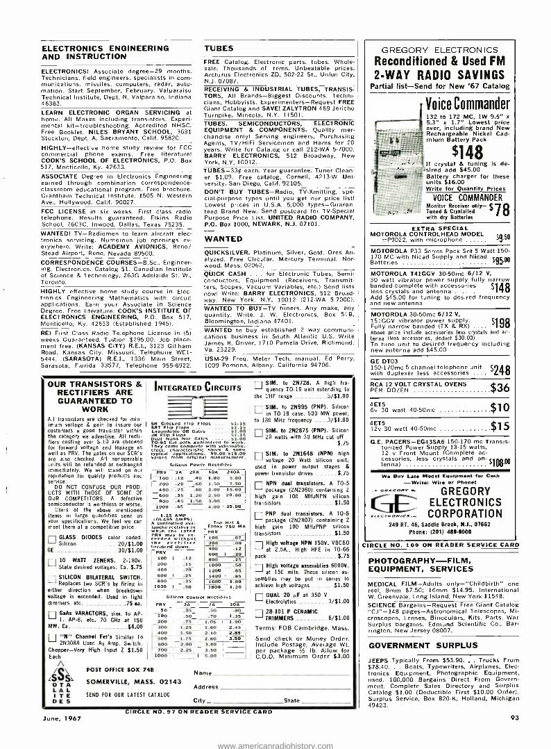
ELECTRONICS ENGINEERING AND INSTRUCTION
ELECTRONICS! Associate degree -29 months. Technicians, field engineers, specialists in com munications. missiles, computers, radar, auto- mation. Start September, February. Valparaiso Technical Institute, Dept. N, Valparaiso, Indiana 46383.
LEARN ELECTRONIC ORGAN SERVICING at home. All Makes including transistors. Experi- mental kit -troubleshooting. Accredited NHSC. Free Booklet. NILES BRYANT SCHOOL, 3631 Stockton, Dept. A, Sacramento, Calif. 95820.
HIGHLY -effective home study review for FCC commercial phone exams. Free literature! COOK'S SCHOOL OF ELECTRONICS, P O. Box 517, Monticello, Ky. 42633.
ASSOCIATE Degree in Electronics Engineering earned through combination correspondence - classroom educational program. Free brochure. Grantham Technical Institute, 1505 N. Western Ave., Hollywood. Calif. 90027.
FCC LICENSE in six weeks. First class radio telephone. Results guaranteed. Elkins Radio School, 2603C, Inwood, Dallas, Texas 75235. WANTED! TV- Radiomen to learn aircraft elec- tronics servicing. Numerous job openings ev- erywhere. Write: ACADEMY AVIONICS, Reno/ Stead Airport, Reno, Nevada 89500. CORRESPONDENCE COURSES- B.Sc., Engineer- ing, Electronics. Catalog $1. Canadian Institute of Science & Technology, 263G Adelaide St. W., Toronto. HIGHLY effective home study course in Elec- tronics Engineering Mathematics with circuit applications. Earn your Associate in Science Degree. Free literature. COOK'S INSTITUTE OF ELECTRONICS ENGINEERING, P.O. Box 517, Monticello, Ky. 42633 (Established 1945).
REI First Class Radio Telephone License in (5) weeks Guaranteed. Tuition $295.00. Job place- ment free. (KANSAS CITY) R.E.I., 3123 Gillham Road, Kansas City, Missouri, Telephone WE1- 5444. (SARASOTA) R.E.I., 1336 Main Street, Sarasota, Florida 33577, Telephone 955 -6922.
TUBES
FREE Catalog. Electronic parts, tubes. Whole- sale. Thousands of items. Unbeatable prices. Arcturus Electronics ZD, 502 -22 St., Union City, N.J. 07087. RECEIVING & INDUSTRIAL TUBES, TRANSIS- TORS, All Brands -Biggest Discounts. Techni- cians, Hobbyists, Experimenters- Request FREE Giant Catalog and SAVE!. ZALYTRON 469 Jericho Turnpike, Mineola, N.Y. 11501. TUBES, SEMICONDUCTORS, ELECTRONIC EQUIPMENT & COMPONENTS. Quality mer- chandise only! Serving engineers, Purchasing Agents, TV /HiFi Servicemen and Hams for 20 years. Write for Catalog or call 212 -WA 5 -7000. BARRY ELECTRONICS, 512 Broadway, New York, N.Y. 10012. TUBES -33¢ each. Year guarantee. Tuner Clean- er $1.09. Free catalog. Cornell, 4213 -W Uni- versity, San Diego, Calif. 92105. DON'T BUY TUBES -Radio, TV- Xmitting, spe- cial- purpose types until you get our price list! Lowest prices in U.S.A. 5,000 types- Guaran- teed Brand New. Send postcard for TV- Special Purpose Price List. UNITED RADIO COMPANY, P.O. Box 1000, NEWARK, N.J. 07101.
WANTED
QUICKSILVER. Platinum, Silver, Gold. Ores An- alyzed. Free Circular. Mercury Terminal. Nor- wood, Mass. 02062. QUICK CASH . for Electronic Tubes, Semi- conductors, Equipment (Receivers, Transmit- ters, Scopes, Vacuum Variables, etc.) Send lists now! Write: BARRY ELECTRONICS, 512 Broad- way, New York, N.Y. 10012 (212 -WA 5- 7000). WANTED TO BUY -TV tuners. Any make, any quantity. Write. J. W. Electronics, Box 51B, Bloomington, Indiana 47401. WANTED to buy established 2 way cations business in South Atlantic James R. Driver, 1710 Pamela Drive, Va. 23229.
cornmuni- U.S. Write Richmond,
USM -29 Freq. Meter Tech. manual. Ed Perry, 1009 Pomona, Albany, California 94706.
OUR TRANSISTORS & RECTIFIERS ARE GUARANTEED TO
WORK All transistors are checked for min- imum voltage & gain to insure our customers a good transistor within the category we advertise. All recti- fiers costing over $.10 are checked for forward voltage and leakage as well as PRV. The gates on our SCR's are also checked. All nonoperable units will be refunded or exchanged immediately. We will stand on our reputation for quality products and service.
DO NOT CONFUSE OUR PROD- UCTS WITH THOSE OF SOME OF OUR COMPETITORS. A defective semiconductor is worthless or worse.
Users of the above mentioned items in large quantities send us your specifications. We feel we can meet them at a competitive price.
GLASS DIODES color coded. Silicon 20/51.00
6E 30/51.00
E 10 WATT ZENERS 2 -180v. State desired voltages Ea. 5.75
n SILICON BILATERAL SWITCH. Replaces two SCR's by firing in
either direction when breakdown voltage is exceeded. Used in light dimmers, etc. 75 ea.
r7 GaAs VARACTORS, sim. to AP- 1, AP -6, etc. 70 GHz at 150
MW. Ea. $4.00
El "N" Channel Fet's Similar To 2N3088 Used As Amp, Switch,
Chopper -Very High Input Z $1.50 Each
A
[S/S\S O T A L A L I T E D E S
INTEGRATED CIRCUITS
SR Clocked Flip Flops $1.15 SRT Flip Flops $1.15 Expandable OR Gates $1.00 .1K Flip Flops $1.15 Dual Nand Nor Gates $1.00 70 -85 flat pack guaranteed to work. "hey come complete with schematic. elect. characteristic sheet & some typical applications. 59.00- $15.00 values from original manufacturer.
Silicon Power Rectifiers PRV 3A 20A 40A 240A
100 .10 .40 1.00 5.00 200 .20 .60 1.50 7.50 - 400 .25 .80 2.00 15.00 600 .35 1.20 2.50 20.00 800 .45 1.50 3.00
1000 .6s-_. 4.00 35.00
1.25 AMP (GLASS AMPS)
A controlled ava- lanche rectifier in whih the rated PRV may be ex- ceeded without the rectifier breaking down.
PRv 100 .12 200 .15 400 -.20 600 I .25 800 .35
I 1000 I - .50
POST OFFICE BOX 74B
Top Hat & Epoxy 750 MA PRV 100 200 400 600 800 1000 1200 1400 1600 1800
.07 I .09
.12 I .20
.25 I .50
.65 I .85
1.00 1.20
Sol con Control Rectifiers PRV 3A /A ' 20A
50 .35 .50 .80 100 .50 .70 1.35 200 .75 I 1.05 1.90 300 1.25 1.60 ' 2.45 400 1.50 2.10 2.85 500 1.75 2.80 3.50 600 2.00 3.00 700 ' 2.25 3.50
I
1000 I I 5.00 I
SOMER V ILLE, MASS. 02143
SEND FOR OUR LATEST CATALOG
SIM. to 2N728. A high fre- quency TO 18 unit extending to
the UHF range 3/51.00
ri SIM. to 2N995 (PNP). Silicon in TO -18 case. 500 MW power,
to 180 MHz frequency 3/51.00
SIM. to 2N2875 (PNP). Silicon 20 watts with 30 MHz cut off
$.75
n SIM. to 2N1648 (NPN) high voltage 20 Watt silicon unit,
used in power output stages & power transistor drives $.75
n NPN dual transistors. A TO -5 package (2N2060) containing 2
high gain 100 MHzNPN silicon transistors 51.50
n PNP dual transistors. A TO -5 package (2N2807) containing 2
high gain 100 MHzPNP silicon transistors $1.50
n High voltage NPN 150V. VBCBO at 2.5A., High HFE in TO -66
pack $.75 I High voltage assemblies 60001/. at 150 mils. These silicon as-
semblies may be put in series to achieve high voltages $1.50
ri DUAL 20 µF at 350 V
Electrolytics 3/$1.00
n 28 -101 P CERAMIC TRIMMERS 6/51.00
Terms: FOB Cambridge, Mass.
Send check or Money Order. Include Postage, Average Wt. per package 1/z lb. Allow for C.O.D. Minimum Order $3.00
Name
Address
City State
CIRCLE NO. 97 ON READER SERVICE CARD June, 1967
GREGORY ELECTRON ICS
Reconditioned & Used FM 2 -WAY RADIO SAVINGS
Partial list -Send for New '67 Catalog
Voice Commander 132 to 172 MC, 1W 9.5 "x 5.3" x 1.7" Lowest price ever, including brand New Rechargeable Nickel Cad - mium Battery Pack
$148 If crystal & tuning is de- '- sired add $45.00 Battery charger for these units $16.00
` Write for Quantity Prices
VOICE COMMANDER f rS Monitor Receiver only - x^
Tuned & Crystalled 78 with dry Batteries
EXTRA SPECIAL MOTOROLA CONTROLHEAD MODEL - $
P9022, with microphone $9.50
MOTOROLA P33 Sertes Pack Set 5 Watt 150- 170 MC with Nicad Supply and Nicad Batteries
MOTOROLA T41GGV 30.50mc 6/12 V, 30 watt vibrator power supply fully narrow banded complete with accessories $ , A O less crystals and antenna ` U Add $45.00 for tuning to desired frequency and new antenna
MOTOROLA 30 -50mc 6/12 V, T51GGV vibrator power supply. $Qp Fully narrow banded (TX & RX) . X700
Above price include accessories less crystals and an- tenna (less accessories, deduct $30.00) To tune unit to desired frequency including new antenna add $45.00
GE DT03 150 -170mc 5 channel telephone unit 52t with duplexer less accessories .... `Fv
RCA 12 VOLT CRYSTAL OVENS L PER DOZEN Cl
4ET5 $ 10 6v 30 watt 40 -50mc
42T5 $1
C 12v 30 watt 40 50mc J G.E. PACERS- EG43SA6 150 -170 me Transis-
torized Power Supply 13 -15 watts, 12 v Front Mount (Complete ac- cessories, less crystals and an- tenna) tenna) $1u011°
We Buy Late Model Equipment for Cash -Write; Wire or Phone!
RF.. GREGORY CE ELECTRONICS EceGrON,W=._. CORPORATION
249 RT. 46, Saddle Brook, N.l., 07662 Phone: (201) 489 -9000
CIRCLE NO. 109 ON READER SERVICE CARD
PHOTOGRAPHY -FILM, EQUIPMENT, SERVICES
MEDICAL FILM -Adults only -"Childbirth" one reel, 8mm $7.50; 16mm $14.95. International W. Greenvale, Long Island, New York 11548.
SCIENCE Bargains- Request Free Giant Catalog "CJ" -148 pages -Astronomical Telescopes, Mi- croscopes, Lenses, Binoculars, Kits, Parts, War Surplus bargains. Edmund Scientific Co., Bar- rington, New Jersey 08007.
GOVERNMENT SURPLUS
JEEPS Typically From $53.90. , . Trucks From $78.40. . . Boats, Typewriters, Airplanes, Elec- tronics Equipment, Photographic Equipment, used. 100,000 Bargains Direct From Govern- ment. Complete Sales Directory and Surplus Catalog $1.00 (Deductible First $10.00 Order). Surplus Service, Box 820 -K, Holland, Michigan 49423.
93
www.americanradiohistory.com

G&G CATALOG! NEW
24 Popes - the BEST in Military Electronic Gear. SEND NOW FOR YOUR COPY! Please include 250 Refunded wish first order
FAMOUS BC -b45 TRANSCEIVER 15 Tubes 435 to 500 MC Easily adapted for
mmunicatlon, Voice code, on ham band 420-450
mc. citizens radio 460.4711 mc. fixed and mobile 450. 460 ,n
c television expert. mental 470 -500 me. Now
460 to 490 , With tubes. less power sup- ply in factory carton. Still, ping weight 25 lbs.
OUR LOW PRICE Dynamotor, Antenna. Plugs, Ail Accessories Available
LORAN APN -4 FINE QUALITY
NAVIGATIONAL EQUIPMENT 4-Channel long range dual units. will determine exact geographic position of your boat or plane. Indicator and receiver complete with all tubes and crystal. INDICATOR ID -6B /APN -4, and RECEIVER t . 50 R -9B /APN -4, romp, etc with tubes taxe. Used s
LORAN R -65 /APN -9 RECEIVER & INDICATOR
4- Channel single tait system, used In chips and ir-raft. t Determines position by radio r!gnals from known xmitters. Accurate to within 1 , , of distance. complete with tunes :val crys- tal. ó$'S0 IN LIKE NEW Condition. All Accessories for Loran Equipment in stuck.
AN /APR -4Y FM & AM RECEIVER "FB" FOR SATELLITE TRACKING!
High precision lab instrument. for monitoring and t
t' urin frenuency and relative signal strength, 38 to 411011 Me. in 5 tuning ranges. For 1111 V 60 cycle AC. Built -in power supply. Original circuit
o0 ///
,5 C
0 diagram included. Checked out, perfect, NEW
All Tuning Units Available for Above
SCR -274 -N, ARC -5 COMMAND SET HQ! Freq. Exc. BRAND Range Type Used NEW RECEIVERS, Complete With Tubes 190 -550 Kc 13C -453 ...$18.95 $23.50 3 -6 Mc BC -454 ...$16.50 $21.50 6-9.1 Mn. BC -455 ... $14.95 $19.95 1.5 -3 Mc. R -25 - 521.50 TRANSMITTERS, Complete with Tubes 4-5.3 Mc. BC -457 .. .$ 6.95 $11.95 5.3 -7 Mc BC -458 .. .$ 6.95 $12.95 7.9.1 MC. BC -459 ...$17.95 $22.50 2.1.3 Mc. T -18 .. 510.95 3 -4 Mn. T19 ..510.5- 0 $14.95 MODULATOR, Complete with 3 Tubes Voice BC -456 .. .5 2.75 5 4.95 All l'omnuotd Set Arressmies in Stock SCR -625 MINE DETECTOR $32.50 EE -8 FIELD PHONES, Exc. Used. Each 516 95 BC -221 Freq. Meter, Modulated, Exc. Used.. $129.50 BC -221 Freq. Meter, Unmodulated, Exc. Used $79.50 LM Freq. Meter, Exc. Used $79.50 BC- 1206 -C Beacon Reeve, 200 -400 Kc, NEW 512.95 SCR -522 Transm.tter- Receiver, Like New $39.50 TG -34A CODE KEYER r ,14.50 Iirami New in original carton Exc. Used $18.95 Practise Tapes available. With Eeyee P U R
EE -8 FIELD PHONES I'hecked out. perfect , rking prie''. C'onm Iole With all pats. ESreDent l'onditlon. I.IKE: NEW! $16.95 Eann DYNAMIC MIKE, f.,Iv Impedance. switch, rubber c c retl cable with plug, Ne,v $2.65 Please include 25 % Deposit with order -Bal- ance C.O.D., or Remittance in Full. 500 Han- dling Charges on all orders under $5.00. All shipments F.O.B. Our Warehouse, N.Y.C. All Merchandise subject to Prior Sale and Price Change.
G & G RADIO SUPPLY COMPANY Telephone: (212) CO 7 -4605
75 -77 Leonard St., New York N.Y. 10013
EDUCATIONAL OPPORTUNITIES
LEARN While Asleep, hypnotize with your re- corder, phonograph. Astonishing details, sensa- tional catalog free! Sleep- Learning Association, Box 24 -ZD, Olympia, Washington 98501. USED Correspondence Courses and Books sold and rented. Money back guarantee. Catalog free. (Courses Bought). Lee Mountain, Pisgah, Alabama 35765. LEARN WHILE ASLEEP. Miraculously build Mind Power, achieve Self Confidence, improve Health, gain Success. Method 92% effective. Details free. ASR Foundation. Box 7021 Henry Clay Station, Lexington, Kentucky 40502.
RUBBER STAMPS
RUBBER ADDRESS STAMP $1.50. SIGNATURE $2.88. FREE CATALOG. JACKSON PRODUCTS, 1433 WINNEMAC, CHICAGO, ILL. 60640.
94
TAPE & RECORDERS
RENT STEREO -8 CAR TAPES. 100 /day. Send refundable $10.00 deposit and name of first selection. Autotapes, Box 19086 -E, Indianapolis, Ind. 46219. BEFORE renting Stereo Tapes, try us. Postpaid both ways -no deposit- immediate delivery. Quality- Dependa bility- Service- Satiisfaction- prevail here. If you've been dissatisfied in the past, your initial order will prove this is no idle boast. Free Catalog. Gold Coast Tape Library, Box 2262, Palm Village Station, Hialeah, Fla. 33012. STEREO TAPES. Save up to 60% (no member- ship fees, postpaid anywhere USA). Free 60- page catalog. We discount batteries, recorders, tape accessories. Beware of slogans "not un- dersold," as the discount information you sup- ply our competitor is usually reported to the factory. SAXITONE, 1776 Columbia Rd., Wash- ington, D. C. 20009. RENT Stereo Tapes -over 2,500 Different -all major labels -free brochure. Stereo -Parti, 1616 -E. W. Terrace Way, Santa Rosa, California 95404. TAPE RECORDER SALE. Brand new, nationally advertised brands, $10.00 above cost. Arkay Sales, 1028 -B Commonwealth Avenue, Boston, Mass. 02215. HI -FI Components, Tape Recorders at guaran- teed "We Will Not Be Undersold" prices. 15- day money -back guarantee. Two -year warranty. No Catalog. Quotations Free. Hi- Fidelity Cen- ter, 239 (LT) East 149th Street, New York 10451. RENT STEREO TAPES -75¢ week. Catalog. Art's, 1442 Blaze, Simi, Calif.
HIGH FIDELITY
FREE! Send for money saving stereo catalog #E6W and lowest quotations on your indi- vidual component, tape recorder or system re- quirements. Electronic Values Inc., 200 West 20th Street, N.Y., N.Y. 10011. HI -FI Components, Tape Recorders at guaran- teed "We Will Not Be Undersold" prices. 15- day money -back guarantee. Two -year warranty. No Catalog. Quotations Free. Hi- Fidelity Cen- ter, 239 (L) East 149th Street, New York 10451. HIFI EQUIPMENT -GET Our "ROCK BOTTOM" prices on NAME BRAND amplifiers- tuners- tape -recorders - speakers FRANCHISED - 59 YEARS IN BUSINESS. Write for this month's specials -NOW! Rabson's 57th St., Inc., Dept. 569, 119 W. 58th St., New York, New York 10019. LOW, LOW quotes: all components and re- corders. Hi -Fi, Roslyn, Penna. 19001. HI -FI components, tape recorders, sleep learn equipment, tapes. Unusual Values. Free cat- alog. Dressner, 1523 R Jericho Turnpike, New Hyde Park. N.Y. 11040. FISHER KX -200: wired. New tubes. $100.00. Balch, 611 Livingston Rd., Linden, N.J. 07036. EVERYONE can afford HIGH -FIDELITY compo- nents- because of our DISCOUNT policy. In- sured guaranteed shipments- Factory sealed cartons -FRANCHISED- Send for our LOW -LOW quote today. Sound and Sight Audio, Inc., 106 West 32 Street, New York, N.Y. 10001.
HYPNOTISM
FREE Hypnotism, Self- Hypnosis, Sleep Learning. Catalog! Drawer H400, Ruidoso, N.M. 88345. HYPNOTIZE FEMALES!- Unnoticed! Instantly! Nerves! Exciting! Send $2.25. Research Enter- prises, 29 -SN21 Samoset, Woburn, Mass. 01801. FEMALE HYPNOTISM!! Easily! Instantly! Secret Nerve Centers! $2.20. Brugenheimer Publishers, Box 158 -E30, Lexington, Mass.
AUTHORS' SERVICES
AUTHORS! Learn how to have your book pub- lished, promoted, distributed. FREE booklet "ZD," Vantage, 120 West 31 St., New York 10001. SONGWRITERS WANTED! Send song material for recording consideration. Tin Pan Alley, 1650 Broadway, New York 10019.
BUSINESS C PJRTUNITIES
INVESTIGATE Accidents -Earn $750 to $1,400 monthly. Men urgently needed. Car furnished. Business expenses paid. No selling. No college education necessary. Pick own job location. In- vestigate full time. Or earn $6.44 hour spare time. Write for Free Literature. No obligation. Universal, CZ6, 6801 Hillcrest, Dallas, Texas 75205. FREE BOOK "990 Successful, Little -Known Busi- nesses." Work home! Plymouth -145L, Brooklyn, New York 11218. I MADE $40,000.00 YEAR by mailorder! Helped others make money! Start with $10.00 -Free proof. Torrey, Box 318 -N, Ypsilanti, Michigan 48197. FREE CATALOGS. Repair air conditioning, re- frigeration. Tools, supplies, full instructions. Doolco, 2016 Canton, Dallas, Texas 75201. LEARN TECHNICAL WRITING -at home. High paying prestige careers not requiring college. Growing demand, all industries for tech writers now. Low monthly tuition. Easy to understand. FREE career book, sample lesson. APPROVED FOR VETERANS. American Technical Writing Schools, Dept. EWC -67, 5512 Hollywood Blvd., Hollywood, Calif. 90028. MAKE up to $10,000 a year raising chinchillas, mink, rabbits or guinea pigs for us. We supply breeding stock, equipment and feed. Send $1.00 for catalog and complete information. Keeney Brothers Farms, Dept. ZE, New Freedom, Pa. 17349.
EMPLOYMENT INFORMATION
FOREIGN and USA job opportunities available now. Construction, all trades. Earnings to $2,- 000.00 monthly. Paid overtime, travel, bonuses. Write: Universal Employment, Woodbridge, Con- necticut 06525.
YOUR RÉSUME -Make it sell you! Instructions, samples: $2. Executive, Box 246EL, Montclair, N.J. 07042.
GIANT WEATHER BALLOONS 'Bally of fol," I,I.. tr:l6ìc oppc for ao , -ilic for tatour. ,ulcorulu_Li.` ,cate gbborhood GI e:lt
beickyard fun. ExcitlugI,earh at- tacton. Marie of heavy ,htty prene. Inßate With ,lealc,er
tutu ai,' hosc: Or aio nl lY .0.01- able helium for high 1 = .
t60, 568AK (8' diami $2 Ppd. _60, 632AK (16' diam) 57 Ppd.
FASCINATING MOIRE PATTERN KITS Now explore the
c` orld of "0I
feet.. Limitless hobbyist.,
suons. i.ill's of uses for iltlenvists, photographers, hontain péri basic o. Fun! l'rolita
both clear
8 basic patorns both clear : late and white ook. Okele. 1511 dut cs n film. book. Other cots Incl. , negatives es :n ailabl e. Write cor detan.tr" Stock No. 70,719A1(..$8.50 Ppd.
SAME KIT IN FULL COLOR Stock No. 60,530AK..$12.50 Ppd. ,
NEW SURPLUS NI -CD BATTERIES
n,,,, ...
Loy,.-ou.'r rl Order u.
40,986AK
Save more than Long ¡He- cl. il(t alit chaI-'.7e and disch:u' e
es. 1 .25 \' "Its per cell- I o0 inllli:mtper hours capacityy. Excel. charge retention. Hermetically al,',l. Indefinite storage Ilfe. delde,i" series-easily -ut. l'o to
ial. x 10ssc high. Spec, price for I) 11 up. separate.
Cells DC Volt. Price Ppd. 1.25 S 1.50 40,957ÁK 2 2.50 2,75 60,633AK 3 3.75 3.60 60.634ÁK 4 5.00 4.80
70 812A Trickle Charger (1.10 cells) 10.95 Edmund Scientific Co., Barrington, N.J. 08007
MAIL COUPON for FREE CATALOG SEND FOR FREE CATALOG "AK" í Compltely New 1967 edition. Ne items, categornew illustrations. 148 easy - to- alt p'tges packed with nearly 401111
I:d items. 1:nt selection of 1 t ronon. ira! Telescopes, Microscopes, Binoculars. Magnifiers, Magnets, Lenses, prisms. MIanY urplus Items: for hobbylsls. experim nters. workshop. factory. Write for Catalog' "AK." I..41-
Jeun entific Co., Barrington, N, v rsey i 181107.
EDMUXO
NAMF
ADDRFS-1
CITY STATE
CIRCLE NO. 93 ON READER SERVICE CARD
ELECTRONICS WORLD
www.americanradiohistory.com

PERMANENT PROTECTION !
Electronics World Deluxe Magazine Files
that hold a full year's copies!
Designed to keep your periodicals orderly and easy to refer to. These
durable files guard against soiling, tearing, wear or misplacement of issues. They look, feel like leather and are washable! 23kt. gold lettering and exquisite 2 -color binding make them highly -deco- rative additions to your bookshelves.
Shipped POSTPAID! FULLY GUARANTEED!
Only $3.50 each -3 for $10, 6for $19 Order several today -for ELECTRONICS WORLD
and all your other favorite magazines. r
Jesse Jones Box Corp., Box 5120, Dept. EW Philadelphia 41, Pa.
Enclosed is $ - - Please send me Electronics World Magazine Files in the colors checked below:
Black backing /maroon sides
Maroon backing /black sides
1
NAME
ADDRESS
CITY STATE ZIP CODE
Orders outside U.S.A. please add $1 additional for each file ordered.
I_ - - - (Payment must accompany order) J FOREIGN EMPLOYMENT. Construction, other work projects. Good paying overseas jobs with extras, travel expenses. Write only: Foreign Service Bureau, Dept. D, Bradenton Beach, Florida 33510.
INVENTIONS WANTED
INVENTORS. We will develop, help sell your idea or invention, patented or unpatented. Our national manufacturer clients are urgently seeking new items for outright cash sale or royalties. Financial assistance available. 10 years proven performance. For free informa- tion, write Dept. 42, Wall Street Invention Bro- kerage, 79 Wall Street, New York, N.Y. 10005.
PATENT SEARCHES, $6.00! FREE "Invention Record" /Information. Miss Hayward. 1029HE Vermont, District of Columbia 20005. INVENTIONS -IDEAS developed: Cash /Royalty Sales. Member: United States Chamber Com- merce. Raymond Lee, 130 -GE West 42nd, New York City 10036.
INVENTIONS wanted! Highest cash or royalties. Financial assistance. Free analysis. International Invention Institute, Dept. 31, 160 Broadway, New York, New York 10038.
INVENTORS! Get your "Little Piggy" to market. Highest cash or royalties. New York Invention Service, Dept. 13, 160 Broadway, New York, N.Y. 10038.
COINS
MAKE DOLLARS from your pennies!! U.S. Coin Guide: What Coins to Save: Complete Informa- tion. $1.25. WINDHOOK, Box 652AB, Port Wash- ington, N.Y. 11050.
DO -IT- YOURSELF
PROFESSIONAL ELECTRONICS PROJECTS - $1.00 up. Catalog 25e. PARKS, Box 25565B, Seattle, Wash. 98125.
June, 1967
MISCELLANEOUS
WINEMAKERS: Free illustrated catalog of yeasts, equipment. Semplex, Box 7208, Minne- apolis, Minn. 55412.
EMPLOYMENT Resumes. Get a better job & earn more! Send only $2.00 for expert, complete Re-
sume. Writing Instructions. J. Ross, 80 -34 Kent St., Jamaica. N.Y. 11432 Dept. EW.
MONEY WE PAY $10 hr. for NOTHING but your opinions, written from home about our clients' products and publications, sent you free. Noth- ing to buy, sell, canvass, or learn. No SKILL. NO GIMMICKS. Just honesty. Details from RE-
SEARCH, ZD -3, Box 669, Mineola, N.Y. 11501.
STOP BURGLARS THE EASY WAY!! Affix au- thentic "Protected by Electronic Sentry Alarm" Decals to auto windows, doors & windows of home, retail stores, vending machines, etc. Whether you have an alarm or not -thieves stay away! Only $1.00 for each set of two. J. Ross, 80 -34 Kent St., Jamaica, N.Y. 11432. Dept. EW.
STOP SMOKING! Hypnotist's proven method. LP recorded sessions. $4.50. HYPNOSMOKE, Box 231, Belmont, Massachusetts. BEERS, PEACH BRANDY. WINES- Strongest For- mulas, $2.25. (Complete brew supplies hydrom- eters catalog included)- Research Enterprises, 29 -D Samoset, Woburn, Mass.
AS YOU SCAN THESE COLUMNS. more than 185,000 monthly buyers of ELECTRONICS WORLD are doing the same. These men are all Electronics Professionals -individuals involved actively in electronics from a business or hobby viewpoint. They look to the pages of the ELEC- TRONICS MARKET PLACE for prime sources of products and services of interest to them. They will buy from you if your advertising appears regularly in their favorite magazine. Use the handy order form printed in this section or write today to: Hal Cymes, Classified Advertising Man- ager, ELECTRONICS WORLD, One Park Avenue, New York, New York 10016. REMEMBER: August issue, on sale July 20th, closes June 1st.
BCATALOG ' r World's "BEST BUYS" in GOV'T. SURPLUS
Electronic Equipment
NAVY MARINE WALKIE TALKIE NAVY Marine Band WALKIE- TALKIE TRANSMITTER & RECEIVER -This equip- ment is crystal controlled and can be operated on any one channel in the fre- quency range of 2.3 to 4.5 MC. Voice (A3) communication only, output of trans. is 0.2 watts and satisfactory com- munication between units over average terrain should be able to be maintained up to approx. one (1) mile. With tubes: 1 /1S5. 1 /1R5, 2/174, 3/3S4. Voltages required 67.5 VDC 3 MA; 135 VDC 4 MA; 1.5 VDC 225 MA for Rec. -67.5 VDC 1.5 MA; 135 VDC 19 MA; 1.5 VDC 225 MA; & -6 VDC 30 MA for Trans. Unit comes in a waterproof plastic case with space for bait. or power supply. Telescoping antenna 8 ft. has special loading coil. Complete with tubes, antenna, 2 crystals FT -243 (no choice of freq.), headphones, carbon mi- crophone, canvas cover, & manual. Size: 8 x $f17 AC 8 x 21/2 "; Wt.: 8 lbs. 7JJ NAVY WALKIE- TALKIE DIRECTION FINDER MODEL "DAV" -Same as "MAB" except has a direction finding loop circuit for homing, and comes in a waterproof ply- wood case with web straps for carrying on back or chest. Also complete with tubes, 2 crystals (no choice of freq.) headphones, lip microphone, 8 ft. telescoping antenna. & manual. Size: 14 x 10 x 3 "; $1 95 2. Wt.: 11 lbs. 1 L 7:J VIBRATOR POWER SUPPLY- Designed for use with "MAB" & "DAV" described above. Operates from 6 VDC storage battery N -T -6, that fits on bottom of P. S. pack, 6 V 4 A (Can be operated from any 6 VDC 4 A source) supplies 1.5 VDC .3 A; -6 VDC .02 A; 67.5 VDC .005 A; 135 VDC .02 A. Size: $6.95 61/2 x 334 x 13/4 "; Wt.: 2 lbs. NEW N -T -6 PLASTIC STORAGE BATTERY For above Power Sup- ply CRF -20221 A- Supplies 6 volts DC 4 Amp. Size: 31/2
x 21/2 x 2 "; Wt.: 2 lbs. Dry charge battery . ....$3.95
NEW CATALOG JUST OFF PRESS -SEND 250 (stamps or coin) and receive 502 CREDIT on your order! Address Dept. EW Prices F.O.B. Lima, O.
25% Deposit on C.O.D.'s
FAIR RADIO SALES 1016 E. EUREKA Box 1105 LIMA, OHIO 45802
si:,.,
....___
.\j k/ MONEY
A SW" sALE FREE
WORTH OF Transistors
Rectifiers Knobs Condensers Coils, eta.
25C for handling
BACK GUARANTEE
DOUBLE BONUS
Include
P
L
U S
$ FREE
POLY PAK OF YOUR CHOICE
BOTH FREE WITH EVERY $10 ORDER
New! 'PANCAKE' Transistors IN THE NEW TO46 MICRO CASES
ISilicon Epitaxial Planars 70% off Only 1/16" high Gold novar leads 'rested
Like Watts VER' HFE FREOmc NPN LJ' TN706 .4 20 20 200
2N8 .5 120' 80
0 2N16161 3 .8 50 120= 80 2N1893 .8 100 120' 70
Li 2N2049 .8 50 300 85
12N2434 .5 80 185 100 Fo or 7N2645 .5 50 300' 85
PRV aa PRV ", SILICON 3
CONTROLLED Ióó 50 400
1 ! 1.10 AMPS. RECTIFIERS 200 (:1 30 600 ' ! 2.50
(,R 1 AMP SUBMINIATURE 4 1 000 P V RECTIFIERS for $1
i Nk1. Delco
f ! LIKE
. 05501
INTEGRATED G
CIRCUITS r
6 for S' 88 í;::.i75 ¢
EA,
OTRANSISTORS PNP t00Watt /tSAma HIP..er 7036 Oise! up to S6 YNts
Flip Flops .'r Nand Nor cates Jc o' Dual- inline. 70 -5. P`
¿. r4 i4;1 V.M, V.M, V.1N VH, 5.4 18 4:t 100 82
RECTIFIERS 6.4 20 47 91 ItO 8.0 22 AI 120
-t HALF WATT .29 91 24 SB 130
, I 1 -WATT 45 IO 27 eZ 150
Li to WATTS ,Iì5 1; 33 75 180
1 AMP TOP"Pa EPDXIE pMU
- PIV Sale PIV Sale PIV Sale ` 50 Ll 5e 600 ' 19e 1400 H I 69e 100 I! 7e 800 25e 1600
' 8f 200 9e 1000 454 1800 ;' 9 400 L, 1 1 e 1200 H 59e 2000 ' 1.50*
SILICON POWER STUD RECTIFIERS
AMPS Tlla,toyy 50 PlY 100 PI` 200 PIV
,1.1,,1 ed Í
.
22e 40e .i 65e 45 75e 90c 1.25
AMPS 400 PIV 600 PIV 800 PIV 1000 PIV 3 22e I 31e 40a : 59e
15 90t ' 1.35 1.59 1.79 45 ' 1.59 1.90 2.50 2.95
'GLASS AMP' ' ONE AMP , v SILICON PI
RECTIFIERS
PIV Sale PIV Sale so CI 74 600 ¡ I
19e 100 LI 9e 800 I
1 29c
200 1le 1000 I -I 45e 400 I I 134 1200 j ) 59e
1;288-,, e
4.r° 1 <v-" s I]C1. -
O -BOO s ,
k IClicroamp
C
100 FOR OUR "SUMMER" BARGAIN CATALOG ON 7- El Semiconductors Poly Paks Pans
TERMS: send check, money order.
zs
PO LYs
ncIlhu. de Rpd agne e 0
.
d ay. s. pOOn
A K S SO.P BOX
MASS. "PAK- KING" of the World
CIRCLE NO. 101 ON READER SERVICE CARD 95
www.americanradiohistory.com

o
INTEGRATED
CIRCUIT
POWER SOURCE 0 -6VDC, 0 -3A
NEW
Overvoltage & Overcurrent
Crowbar Protection
Avoids damage to delicate integ- rated circuits due to internal power supply failure or load current runa- way.
.01% plus 1 MV regulation
1 MV peak -to -peak ripple
Continuously adjustable current limiter
Coarse and fine voltage adjust- ment with 1 MV resolution.
MODEL 630
$14950 FOBWESTBURY, N.Y.
p-1 POWER DESIGNS, INC.
1700 SHAMES DRIVE WESTBURY, N. Y. 516 EDgewood 3 -6200 TWX: 510 -222 -6561
POWER DESIGNS PACIFIC, INC. 3381 JUNIPERO SERRA PALO ALTO, CALIF. 415- 321 -6111 TWX: 910 -373.1251
ELECTRONICS WORLD JUNE 1967
ADVERTISERS INDEX
READER
SERVICE NO. ADVERTISER PAGE NO. READER
SERVICE NO. ADVERTISER PAGE NO.
125 Allied Radio 60 104 Mallory & Co., Inc., P.R. 22
American Institute of Engineering 200 Mefex Corporation 68 & Technology 74
199 Methods Research Corp 69 124 Antenna Specialists Co., The 4
103 Music Associated 81
123 Belden Manufacturing Company 6, 7
Nationwide Tube Co 91
122 Burstein -Applebee Co 68
Capitol Radio Engineering Institute, The 56, 57, 58, 59 102
National Radio Institute 8, 9, 10,
Pearce -Simpson, Inc
11
61
121 Cleveland Institute of Electronics ....13 101 Poly Paks 95
120 Cleveland Institute of Electronics 195 Power Designs, Inc 96 70, 71, 72, 73
198 Public Service Electric & Gas Co 51 119 Cornell Electronics Co 92
RCA Electronic Components and 118 Delta Products, Inc 53 Devices FOURTH COVER
117 EICO Electronics Instrument Co., 92 RCA Electronic Components and Inc THIRD COVER Devices 15
116 Editors & Engineers, Ltd 66 90 RCA Electronic Components and Devices 75
93 Edmund Scientific Co 94
RCA Institutes, Inc 18, 19, 20, 21
115 Electra- Voice, Inc 67
RCA Sales Corp 2
114 Electronics Chemical Corp 74
100 Radar Devices Manufacturing Corp .. 5
113 Electronic Components 91
99 Schober Organ Corporation, The . 69
Fair Radio Sales 95
98 Scott, Inc., H.H. 12
112 Finney Company, The 67
89 Shure Brothers, Inc 67
91 Finney Company, The 84
97 Solid State Sales 93
G & G Radio Supply Co 94
96 Sony Corp. of America 66
111 Goodheart Co., Inc., R.E. 92
88 Sony /Superscope, Inc 16
110 Greenlee Tool Co 81
95 Surplus Center 91
109 Gregory Electronics Corporation 93
197 Sylvania Electronic Tube Division .. 17
108 Heath Company SECOND COVER
1, 62, 63 196 Texas Crystals 60
106 Judson Research and Mfg. Co. 84 Valparaiso Technical Institute 55
105 Lampkin Laboratories, Inc. 55 94 Zenith 79
CLASSIFIED ADVERTISING 91, 92, 93, 94, 95
CIRCLE NO. 195 ON READER SERVICE CARD Printed in U.S.A. 96 ELECTRONICS WORLD
www.americanradiohistory.com
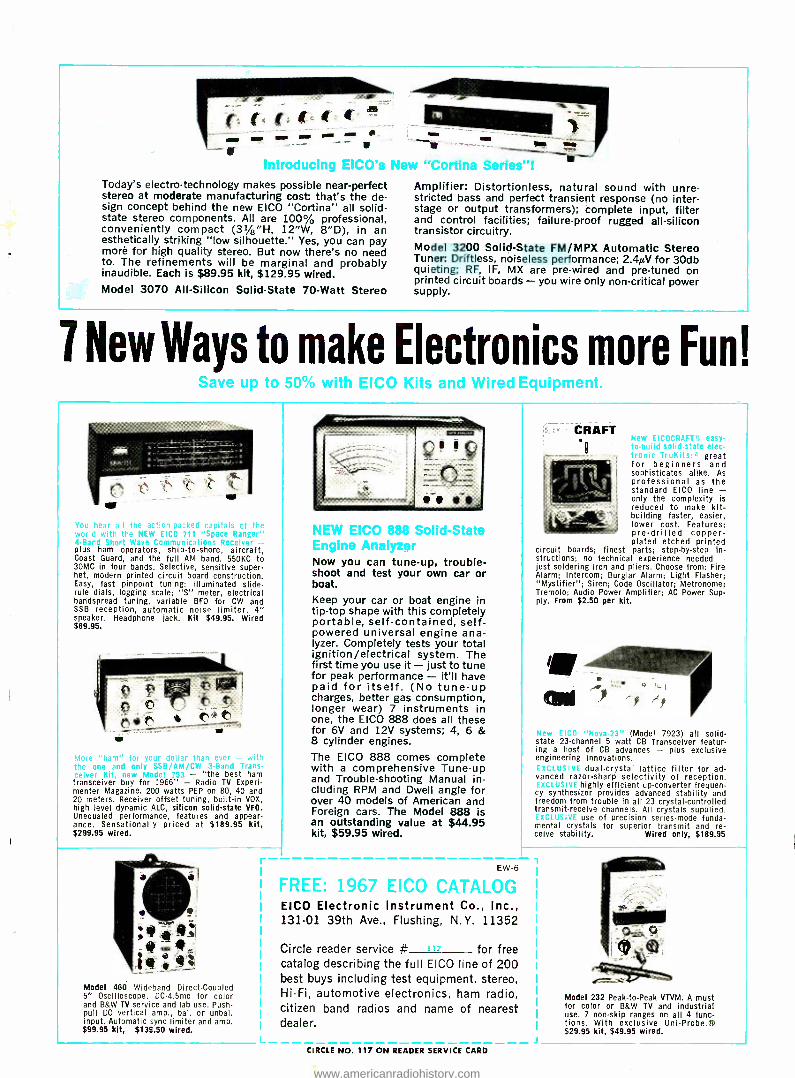
ow am
Introducing EICO's Nei. mine Series! Today's electro- technology makes possible near -perfect stereo at moderate manufacturing cost: that's the de- sign concept behind the new EICO "Cortina" all solid - state stereo components. All are 100% professional, conveniently compact (31/2"H, 12 "W, 8 "D), in an esthetically striking "low silhouette." Yes, you can pay more for high quality stereo. But now there's no need to. The refinements will be marginal and probably inaudible. Each is $89.95 kit, $129.95 wired. Model 3070 All- Silicon Solid -State 70 -Watt Stereo
Amplifier: Distortionless, natural sound with unre- stricted bass and perfect transient response (no inter - stage or output transformers); complete input, filter and control facilities; failure -proof rugged all- silicon transistor circuitry. Model 3200 Solid -State FM /MPX Automatic Stereo Tuner: Driftless, noiseless performance; 2.40V for 30db quieting; RF, IF, MX are pre -wired and pre -tuned on printed circuit boards - you wire only non -critical power supply.
7 NewWays to make Electronics more Fun! up to 50 °! °m °°'1- t°'° °- -id Wired Equipment.
You hear oil the sct n- reeked of the world r
4 -Band plus ham operators, ship -to- shore, aircraft, Coast Guard, and the full AM band. 550KC to 30MC in four bands. Selective, sensitive super - het, modern printed circuit board construction. Easy, fast pinpoint tuning: illuminated slide - rule dials, logging scale; S" meter, electrical baddspread tuning, variable BFO for CW and SSB reception, automatic noise limiter. 4" speaker. Headphone jack. Kit $49.95. Wired $69.95.
More "ham" for your dollar the one and only SSB /AM /CW ceiver Kit. new Model 753 - "the best ham transceiver buy for .966" - Radio TV Experi- menter Magazine. 200 watts PEP on 80, 40 and 20 meters. Receiver offset tuning, built -in VOX, high level dynamic ALC, silicon solid -state VFO. Unequaled performance, features and appear- ance. Sensationally priced at $189.95 kit, $299.95 wired.
Model 460 Wideband Direct -Coupled 5" Oscilloscope. DC -4.5mc for color and B &W TV service and lab use. Push -
pull DC vertical amp., bal. or unbal. input. Automatic sync limiter and amp. $99.95 kit, $139.50 wired.
,O 888 Solio Frvilne Analv7 r Now you can tune -up, trouble- shoot and test your own car or boat.
Keep your car or boat engine in tip -top shape with this completely portable, self -contained, self - powered universal engine ana- lyzer. Completely tests your total ignition /electrical system. The first time you use it - just to tune for peak performance - it'll have paid for itself. (No tune -up charges, better gas consumption, longer wear) 7 instruments in one, the EICO 888 does all these for 6V and 12V systems; 4, 6 & 8 cylinder engines. The EICO 888 comes complete with a comprehensive Tune -up and Trouble- shooting Manual in- cluding RPM and Dwell angle for over 40 models of American and Foreign cars. The Model 888 is an outstanding value at $44.95 kit, $59.95 wired.
.te
EW -6
FREE: 1967 EICO CATALOG EICO Electronic Instrument Co., Inc., 131 -01 39th Ave., Flushing, N.Y. 11352
Circle reader service # for free catalog describing the full EICO line of 200 best buys including test equipment, stereo, Hi -Fi, automotive electronics, ham radio, citizen band radios and name of nearest dealer.
CIRCLE NO. 117 ON READER SERVICE CARD
CRAFT New EICOCRAFTu. easy -
o -hulr snfhd- stair- clec. great
for beginners and sophisticates alike. As professional as the standard EICO line - only the complexity is reduced to make kit - building faster, easier, lower cost. Features: pre -drilled copper - plated etched printed
ci cuit boards; finest parts; step -by -step in- st uctions; no technical experience needed - just soldering iron and pliers. Choose from: Fire Alarm; Intercom; Burglar Alarm; Light Flasher; "Mystifier "; Siren; Code Oscillator; Metronome; Tremolo; Audio Power Amplifier; AC Power Sup- ply. From $2.50 per kit.
e =w Elco -Novo-?3" (Model 7923) all solid - state 23- channel 5 watt CB Transceiver featur- ing a host of CB advances - plus exclusive engineering innovations.
dual -crystal lattice filter for ad- vanced razor -sharp selectivity of reception.
highly efficient up- converter frequen- cy synthesizer provides advanced stability and freedom from trouble in all 23 crystal -controlled transmit -receive channels. All crystals supplied.
use of precision series -mode funda- mental crystals for superior transmit and re- ceive stability. Wired only, $189.95
Model 232 Peak -to -Peak VTVM. A must for color or B &W TV and industrial use. 7 non -skip ranges on all 4 func- tions. With exclusive Uni -Probe.® $29.95 kit, $49.95 wired.
www.americanradiohistory.com
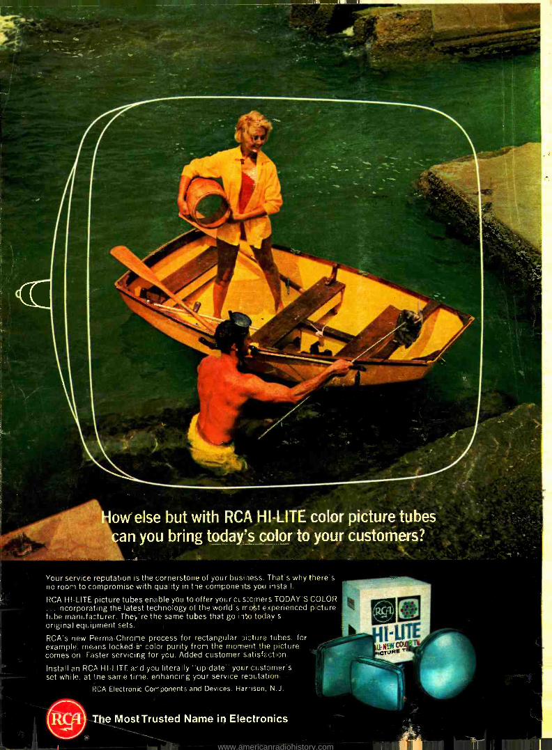
11 111M1,11
ow else but with RCA 1-11-LITE color picture tubes an you bring today's color to your customers?
Your service reputation is the cornerstone of your business. That's why there's no room to compromise with quality in tie componeits you install.
RCA HI-LITE picture tubes enable you to offer your us:criers TODAY'S COLOR ... incorporating the latest technology of the world's rr 4t experienced picture tube manufa:turer. They're the same tubes that go iito today's original equipment sets.
RCA's new Perma-Chrone process for rectangular Di:lure tubes, for example. means locked-in color purity from the moment the picture comes on. Faster servicing for you. Added customer satisfaction.
Install an RCA HI-LITE and you literally "up-date" your customer's set while, at -.le same tine, enhancirg your service reoutatioo.
RCA Electronic Components and Devices, Harmon, N.J.
The Most Trusted Name in Electronics
www.americanradiohistory.com


![Métropole Electroni[k] - Revue de presse](https://img.pdfslide.net/doc/110x75/568ca77d1a28ab186d9591f7/metropole-electronik-revue-de-presse.jpg)