Embed Size (px)
Citation preview

elect? DECEMBER 1977
401
es today international
---- Electronic News Gathering
FreezerAlarm Rev -Monitor
Batteries Explained Electrets
CHESS C PUTER
OFFER
.NEWS . . PROJECTS. . . MICROPROCESSORS. . AUDIO.

ENG is no longer just an ab- breviation for engineer -- Page 14
Your move, page 43.
Digital clock 'par excellence Page 19
INTERNATIONAL EDITIONS
AUSTRALIA Collyn Rivers Publisher Les Bell Assistant Editor
HOLLAND Anton Krieqsman Editor -in -chief
CANADA Steve Braidwood Editor
GERMANY Udo Wittig Editor
ABC
electronicstoa,,j issommwmammomiammimmimmimmin international s& NS FEATURES
ELECTRONICS NEWS GATHERING 14 ELECTRETS IN AUDIO CLASS G AMPLIFIERS
BATTERIES EXPLAINED DIGITAL ELECTRONICS-PART 3
MICROFILE TECH -TIPS
24 34 65 76 81 86
Here we go gathering news in - maybe! Making sound use of spare capacity. A new class - and what class! Teach your-cellf all about the subject. Ian Sinclair takes us past the gates. Gary Evans boards a bus. Two pages of readers' circuits.
PROJECTS MULTI -OPTION CLOCK 19 The ultimate way to tell time!
FREEZER ALARM 30 To let you know when a flood's due! REV MONITOR -LIMITER 37 Guides you through the gears.
TV CAMERA 46 Put yourself firmly in the picture. SYSTEM 68 59 Interfacing and facing up to it!
NEWS NEWS DIGEST 8 The news pages that get it first!
ELECTRONICS TOMORROW 85 TV games are still alive!
INFORMATION ETI SPECIALS 10
OUR BRAND NEW SPECIAL 11 Whats happening tomorrow - today! ETI PRINTS 41 The modern way to produce PCBs.
NEXT MONTH IN ETI 44 SUBSCRIPTIONS 69
ETI CLOCK 79 PANEL TRANSFERS 84 ETI BOOK SERVICE 88
Stick it! Neatly and professionally.
OFFER CHESS CHALLENGER 43 A machine to improve your game.
EDITORIAL AND ADVERTISEMENT OFFICE 25-27 Oxford Street, London. W1 R IRE. Telephone 01-434 1781/2
Halvor W. Moorshead Ron Harris BSc
Gary Evans Diego Rincón
Brenda Goodwin Jim Perry
Tony Alston, John Koblanski Paul Edwards Sandra Cassar
Margaret Hewitt David Lake (Manager), Kim Hamlin, Tim Salmon
Mark Strathern (Manager), Tom Moloney
Editor Assistant Editor Editorial Assistant Art Director Editorial Secretary Specials Editor Project Development Technical Drawings Subscriptions Administration Reader Services Advertising
Telex 8811896
PUBLISHED BY Modmags Ltd. 25-27, Oxford Street, W1R 1RF DISTRIBUTED BY Argus Distribution Ltd. (British Isles)
Gordon & Gotch Ltd. (overseas) PRINTED BY OB Limited, Colchester
Electronics Today International is normally published on the first Friday of the month prior to the cover date.
COPYRIGHT: All material is subject to world wide Copyright protection. All reasonable care is taken in the preparation of the magazine to ensure accuracy but ETI cannot be held responsible for it legally. Where errors do occur a correction will be published as soon as possible afterwards.

DC Volts
AC Volts (40Hz-5KHz)
DC Current
Resistance
Size: Weight: Power requirement:
Sockets:
1 mV to 1.0% ± 1 count 1000 V
1 V to 1.0%± 2 count 500 V
1 nA to 1.0% -11 count 200 mA
1 R to 1.5%±1 count 20 M
. . news
10 M input Impedance
Mean Reading R.M.S. (Calibrated)
Max. Resolution 0.1 nA
Also provides 5
junction -test ranges.
155 x 75 x 30mm 175 gms (Including battery) Throwaway 9 V radio battery or Sinclair AC adaptor (optional extra) Standard 4 mm
Sinclair Radionics Ltd., London Road, St. Ives, Huntingdon , Cambs, PE17 4HJ
low cost DMM
Using the results of a survey, Sinclair Radionics has designed a digital multi - meter that is ideally suited for all round laboratory and workshop use, as well as being fully portable.
Sinclair's new digital multimeter (recognise the case?) the PDM35, incorporates DC voltage and current ranges, resistance ranges, and AC voltage measurement. Full speci- fication is given below.
Accuracy of the meter is within 1% of reading and the unit features a 31/ digit red LED display, angled for ease of reading with a range of ± 1999. The PDM35 is available at a price of £29.95 plus VAT.
MPG meter
A device called a Mileage Computer (what else?) from the Young Corporat- ion in America is designed to produce a digital readout of miles per gallon being obtained from a vehicle at any given instant.
The device is composed of speed and distance sensors, fuel level indi- cator and calculator circuit. A sensor attached to the speedo picks up pulses every revolution to provide some of the info needed.
The MPG meter will sell at around $20 in the USA.
think
It is one of Murphy's laws that the more important a thing becomes, the harder it is to find.
Military users of modern hardware have to rely on fewer maintenance personnel, to perform complex tasks in a shorter time but demand higher quantity and quality of work then found in general industry,
Hughes Aircraft Company has developed a new approach to this problem.
Called Technician's Maintenance Information System (TMIS), a microprocessor -based fault-finding aid.
Traditionally, technicians use "supplementry knowledge" stored in printed manuals. On large systems, such manuals form a stack many feet
8 ELECTRONICS TODAY INTERNATIONAL - DECEMBER 1977

digest ...............
latch onto this
Sintel have produced a range of two, four and six digit latched counter modules in kit form ready built, using both CMOS and TTL ICs. These modules provide a compact unit (at less than the cost of the
components bought seperately), and each contains a set of 0.5" red dis- plays, two PCBs with connecting brackets, ICs, passive components and a single in -line plug and socket for connection to the module.
These counters can be reset to zero and provision is made on the PCB for optional leading/trailing zero blanking. The circuit and assembly instructions are included with each kit. Sintel, P.O. Box 75, Oxford.
In recent editions of ETI the VAT rate on the Bi -Pak advertisement was shown as 81/%. This should of course have read 8%.
high. Even though the manuals may contain the answer needed, they are an entirely passive aid - merely allow- ing the repairman to take whatever help he can find, if he can find it.
The new system consists of a key- board and display unit, and a micro- processor with floppy disc mass memory unit. (A few floppy discs can store all of the trouble -shooting data contained in a large stack of manuals.)
The system can pinpoint the failure from answers the technician provides and tell him which part needs replac- ing, pictorially depict where it is located, and tell him how to change it. It will also explain what tools and test equipment are needed and how to use them.
ELECTRONICS TODAY INTERNATIONAL - DECEMBER 1977
James Bond shopped....
The man with the golden gun, the spy who loved me (and his bank balance), surrounded by the ultimate in elec- tronic gadgetry, would not be very impressed at the manner in which his high technology equipment is chosen for him.
A large number of the devices are in fact rented from Livingston Hire. whose staff are now getting used to dealing with such highly demanding specifications as: `Instruments with lots of switches and flasing lights", or "grey on blue background to go with the props" or "lots of paper coming out and making lots of noises".
Armed with these technical para- meters, Livington Hire then translates the information into the more usual form allowing its computer to process the order. The computer -produced report is then sent to the film agency advising it to take, for example: oscilloscopes, digital voltmeters, signal generators, chart recorders, data log- gers, 4 -channel tape recorders, wave analysers, spectrum analysers, etc. etc. whatever makes the correct noises.
But no matter HOW much infor- mation Mr. Bond's agents are given, the final order always comes back asking for: "50 of the blue ones, two of the ones with paper coming out, ten with the funny noise Livingston Hire Ltd., Shirley Hse., 27, Camden Rd., London. NW1 9NR.
9

Angus Robertson reports on the latest electronic techniques that are rapidly replacing film for TV news reporting
FOR THE LAST 50 years film has remained supreme, first in the cinema and more recently on television, for reporting of both local and overseas news. Cameras have been refined and the latest 1 6mm Ektacolor films are able to produce excellent quality pictures. In fact film stock developments allow better quality from today's 16mm film than from the bulky and expensive 35mm colour film of 20 years ago. Film, however, has one major disadvantage (apart from the fact that it scratches) - it must be chemically processed and edited before it can be shown.
Because processing takes time, reversal film, with lower definition than that obtainable with Ektacolor type neg-pos film is invariably used in TV news reports. Even so processing takes about 45-60 minutes with at least 10 minutes for rush editing to just select the correct section of film. Added to this is transport to the nearest television station from which it may be transmitted, after processing, back, via satellites if necessary, to the news studios. Only a few years ago, most film had to be transported physically to the studios because although many electronic links existed, the same could not be said for colour processing facilities.
Electronic Techniques Introduced During the last five years, electronic techniques have. been increasingly used for news coverage to overcome the time delays that film entails.
Considerable news occurs in late morning and late afternoon when meetings break up and covering news for the lunch time and early evening news bulletins somewhat stretches deadlines. It has been known for unprocessed film to enter the BBC TV Centre basement and be transmitted within 40 minutes, but this sort of urgency causes numerous risks, and once spoilt, film is usually irretrievable.
The availability of portable television cameras, microwave links and portable video tape recorders has changed all this. Full scale television outside broadcast units have brought important events immediately to the screen. Examples being coverage of TUC and party conferences, where several TV cameras and mobile control rooms are set-up for the week. Sometimes OB (outside broadcast) units cover more immediate news stories such as the Flixborough chemical blaze a few years ago.
For the last six years orso, both BBC TV News and ITN have been using two camera OB broadcast units dedicated to news coverage. While the BBC use a
specially built vehicle on a Bedford chassis with two Marconi Mk VIII colour cameras, ITN use a Range Rover with two Fernseh handheld cameras.
BBC and ITN crews often work side -by -side sharing the cost of special lighting required. ITN has a slight edge on set-up and knock-down time, but at least an hour is required for cameras to be unpacked, carried to site, cable laid, and for the microwave link to be carried to the top of the highest buildings (lifts only ever reach
the last but one floor) and lined up with a microwave receiving station. Setting up such a unit costs over a
hundred thousand pounds and requires considerable man power for operation - BBC nine, ITN thirteen, including riggers.
First ENG Station Three years ago, the CBS Television station in St. Louis, Missouri, removed from service all its news film cameras, processing and editing equipment, and has since exclusively used electronic TV cameras and techniques for news coverage. This lead has been followed throughout the United States, and now more than 700 stations are using electronic news gathering (ENG) techniques either exclusively or to supplement film cameras. Many different types of equipment are available for ENG ranging in cost between £5,000 and £100,000 for a single camera, VTR (video tape recorder) and links.
Although the capital cost of the television equipment and its maintenance are considerably more than for a
film camera, the running costs are far less than for film which, when processed, costs around £200 per hour while video tape costs from £12 per hour for a video cassette to £85 per hour for 50mm wide broadcast
The Independent Television News Landrover based unit with two handheld Fernsch cameras.
14 ELECTRONICS TODAY INTERNATIONAL - DECEMBER 1977

standard video tape. Typically, video tape can be re -used up to 200 times, although some programme material will be archived and new tape required to replace it. Some ENG stations in the United States have shown a
saving in film cost of over £50,000 a year. The increased speed with which news may be
brought to the screens is also an important factor in introducing electronic news gathering, additionally, in the USA, where advertising is sold during competing news bulletins, and ratings are all important, any technique that brings news to the screen more rapidly can improve ratings and thus profits.
Although the techniques used by BBC TV News and ITN are an early form of ENG, the recent trend is to a
single camera and, VTR, operating with a two man technical crew and reporter - much the same as a film crew. If microwave facilities are required, additional engineers would probably be required. Fig: 1 shows three different modes of operation possible with a typical ENG unit. In (a) we show the camera alone with a
portable VTR. The tape would be returned to the nearest news centre by despatch rider or sometimes taken back to a support vehicle for replay and transmission via microwave link. Fig 1 (b) shows the camera connected by cable to the support vehicle where the pictures are microwaved back using a 2ft or 4ft dish aerial operating in the 2 GHz band. So that the transmitting dish can be used from the support vehicle at ground level, a centrally located microwave relay station is often installed on a
high building rather than using, the existing receiving stations, which usually require the dish to be taken to roof height. Finally (c) shows a remote camera but to
Television News
CAMERA USED AT DISTANCE FROM VEHICLE
(CI
13 RH, TRANSMITTER
Ibl
overcome the time required to lay a cable back to the support vehicle, a local 13 GHz microwave link is used: Microwave Associates manufacture a 13 GHz link that can be hand held unlike its 2 GHz sisters.
Television camera, portable video tape recorder, and, portable microwave link are all battery powered to eliminate mains or generator problems - the support vehicle links can operate from car batteries but these are hardly portable. Lighting, if required, is generally mains or generator powered but handheld battery 'sun guns'. can be used to provide a high intensity for a few vital minutes. Generally, the more expensive the TV camera,, the less light is required for good pictures. Unfortunate- ly, news often happens so fast that proper lighting is
impossible - one can not ask villains and politicians to wait patiently for a light set - and thus some of the appalling pictures that we see from the USA.
Communications And Links Microwave frequencies are limited, so if several ENG crews are operating in the same area, material must be recorded and sent back to base leaving only late stories to be microwaved back for possible live coverage. Communications are just as important as getting the picture back, and full mobile facilities would be carried in the support vehicle together with separate personal transceivers.
BBC TV News use a multiplexed system which provides five separate channels for engineering and production control telephones, and two way talkback. They use a music bandwidth circuit on a spare
Fg 1. The three main ENG options. (a) shows a camera used with a portable VTR, in (b) a camera is connected by cable to the support vehicle while (c) depicts a remote camera linked to the support vehicle by a 13 GHz local link.
ELECTRONICS TODAY INTERNATIONAL - DECEMBER 1977
CAMERA CABLE
13 GHz RECEIVER
2 GHz TRANSMITTER
SUPPORT VEHICLE (RANGE ROVERI
MICROWAVE RELAY
PORTABLE VTR
CENTRAL TALL BUILDING
LINK TO NEWS CENTRE
15

To the left is a picture of the new Philips LDK-11 colour camera.
To the right a typical ENG outfit is shown
on location at Montreux. The VTR is a portable 25mm
Femseh.
microwave link (or sound-in-syncs), and a VHF communications transmitter in North London for the return circuit. Thus the OB can sit in a field with its own generator and full communication facilities without having to disturb the Post Office. Incidentally, when requested to do so by the right people, the PO can provide a telephone virtually anywhere in a road or car park within a couple of hours.
Equipment For ENG As previously mentioned, there are many different categories of equipment that can be used for ENG ranging from industrial to full broadcast quality. Typical of the equipment in the lower cost range i's the Akai CVC-150/VT150 single tube colour camera and portable VTR for about £4000, but quality is not really up to broadcast standards. Better cameras include the Sony DXC-1600 and JVC GC -4800 at around £3000 with a video cassette recorder for an additional £2000. In fact the Sony VO -3800 U-Matic video cassette recorder is used in a large proportion of ENG operations and is the unit the BBC is initially experimenting with.
To obtain broadcast quality colour pictures, rather more expensive cameras must be resorted to, in other words cameras costing between £15000 and £30000. Cameras in use for ENG include the Ikegami HL33P, Philips LDK- 1 1 (the BBC choice), RCA TK -76 and Fernseh KCA-90. Although the Sony U-Matic video cassette recorder using 1 9mm wide tape is finding wide use in the USA, the picture quality is somewhat less than
The microwave associates 2 GHz microwave link with 4 ft dish. This link would be mounted on the ENG support vehicle and used in conjunction with a receiver located in a high building to relay "live" pictures to the TV studio.
16 ELECTRONICS TODAY INTERNATIONAL - DECEMBER 1977

the accepted broadcast standard in Europe. In fact, television quality in general in the USA leaves rathera lot to be desired and thus the wide use of cheap equipment - nobody notices the difference.
Unfortunately the TV system used in Europe requires a slower tape speed (less fields per second) and yet a wider bandwidth, and this is one reason why Europe will probably standardise on rather better ENG recording equipment.
Although almost certainly 25mm wide tape will be used but there are currently three different formats - Bosch Fernseh (and Philips), Ampex and Sony. The latter are being standardised to one common format, but for technical reasons, the Bosch Fernseh format is never going to be compatible. US broadcasters will probably select the Sony/Ampex format - NBC has already announced that it will not be using any conventional high cost Quadruplex VTRs at the Moscow Olympics, and has reportedly ordered virtually the entire Sony factory output of 25mm VTRs.
Quadruplex video tape recorders such as the Ampex Vif -1200, VR -2000, AVR,1, AVR-2, VR -3, and RCA TR -70 and TR -600, use 50mm wide video tape which costs about £85 per hour - machines cost from £40000 up. Although the same format has reigned for 20 years, commendably so, few new Quadruplex VTRs will be sold over the next decade. There are currently a few stations that use the Ampex VR -3000 which is a suitcase sized portable Quadruplex VTR costing around £40000, producing tapes which can be replayed on a studio VTR. Principal use is for Electronic Field Production (EFP) where inserts for drama and light entertainment programmes are recorded using TV cameras rather than film (such as LWT Love for Lydia).
So, excluding Quadruplex, there are basically two
ELECTRONICS TODAY INTERNATIONAL - DECEMBER 1977
recording formats - the popular and lightweight Sony U-Matic video cassette or the higher quality but heavier, portable 25mm open reel recorders. The former is cheap and easy for non -experienced people to use, while the latter are more expensive (£10000 to £20000) but make full broadcast quality recordings, particularly important for Europe. But there is another difference which has important implications, because recording the programme or interview is only the first step - it must then be edited, however basically, before transmission.
Editing Techniques Video tape editing can not be performed by cutting the tape as with audio recordings but instead electronic editing must be used. The material is replayed from one VTR and recorded onto a second with cuts and sequence changes as required. With conventional editing, this is done using two (sometimes three) Quadruplex. VTRs, but the extremely high capital cost of such equipment (over £100000 for two machines with ancillaries) means that editing time is expensive - commercial facilities charge £100 to £1 50 per hour and editing can be extremely tedious and time consuming - drama can take days to edit.
Although the technique is sound, some means had to be found to reduce the cost for ENG. Since considerable editing time is required for making artistic decisions, savings can be made by making a video cassette copy of the programme 'rushes' and letting the production team make editing decisions at leisure and, when completed, the master tape can be edited on Quadruplex VTRs. This is known as off-line editing and often uses a time code which uniquely identifies each frame so that the production staff simply note frame numbers for the VT editor to follow. Although time code editing has both artistic and financial advantages, there has been certain union resistance to its introduction in the UK, and thus the loss of several Rock Fo/lies episodes earlier this year.
In America, ENG video tape editing is performed using Sony editing U-Matic video cassette recorders which use the cassette as recorded on location to provide a fully edited U-Matic master. Time code is often used to facilitate editing and a number of editing controllers, some using microprocessors, have appeared on the market - Convergence Corporation make such a unit which provides joystick control of edit point location, and a rehearsal before making the actual edit. Although a pair of Sony VO -2850 editing U-Matics and editing controller provide a low cost solution to the editing problem (£10000), the U-Matic cassette is generally transferred to Quadruplex before transmission, so Quadruplex VTRs must also be maintained. However, if recordings are originated on a portable 25mm VTR, the tape may then be edited on studio quality 25mm VTRs which are transmission capable - thus Quadruplex VTRs can be eliminated completely. Using 25mm VTRs throughout has considerable advantages in maintaining high quality through the broadcast chain from portable camera to transmission.
Conclusion Although there hs been slight union resistance to the introduction of electronic news gathering in the UK, and while for some time it will not be economical to replace the many film cameras used by news crews (probably around 100), for many applications ENG will undoub- tedly provide a more economic and beneficial approach to news coverage. Ell
17

MUM -OPTE« CLOCIC
Concluding our digital clock design is a fluorescent display unit with a battery back-up circuit, brightness control and even a volume control for the alarm. As an extra a four year calendar is also included.
THIS MONTH WE conclude our digi- tal clock design based on the Mostek MK50362 chip with a fluorescent dis- play unit. This has been constructed incorporating most of the facilities offered by the 50362 so that between both clocks you have the lot!
Facilities are interchangeable bet- ween the circuits, simply by leaving things off ( and putting things in )
where necessary. For instance both the battery standby and the brightness can be added to the LED clock very simply.
One advantage that the fluorescent version has . is its freedom from inter - wiring between display and PCB. The 5LT02 is mounted directly onto the board, although admittedly there are quite a few links to be incorporated.
Saving Time The back-up feature is to preserve the information stored on all the internal registers within the 50362, and will not keep the clock counting. However since there are two alarm times, and a 'time zone' i.e. independant incremented registor to protect, the facility will save a lot of time.
A PP3 can be used, but the drain (16mA) will not be accommodated for more than a few hours.
Browned off
Upon switching on, the display may well go into the power failure indi- cation, and begin flashing the display at 1 Hz. Switching on and off again will clear the abberation and the dis- play will then stand at 0:00. Time- keeping begins once the 'min set' switch is operated. The switching has been rearranged slightly this month, simply to show there are other ways of doing it than last months arrange- ments.
The seconds display shows the 'part of minute' if you like and resetting this to zero puts the clock at exactly that time, and is handy for setting up.
Constructed Assemble the PCB, working from the component overlay, and use a holder for IC1. Check the polarities of all diodes, electrolytics etc. as it is very easy to put them the wrong way round, and then spend hours wondering why the clock isn't clocking. The links are best fitted to the board first, and the display last. Metalwork is best done once the exact position of the board within the case is known.
Decide which switches you wish to mount on the front panel before you
ELECTRONICS TODAY INTERNATIONAL - DECEMBER 1977
3,Y LI \LS The 5LT02 is not to be confused with the more generally available 5LT01 which is not suitable for this project. As mentioned previously Pronto Electronics can supply you both chip and display for £12.96 all inc. They reside at 645-647, High Road, Seven Kings, Essex. IG3 8RA. Other people to try who may be nearer are Bywood and Metac, both of whom do a good range of clock components. Greenbank are also advertising the 50362 at £7.25, but make sure you get the 50362 and the not 66 which is not pin compatible, and so will not fit any of our boards. Most suppliers will have the rest of the components readily available.
start drilling - think how embarrassing a nice neat hole is gonna look with nothing to fill it - mount these pro- visionally to gauge the length of the leads you'll need to link up with the PCB.
It is always a good idea to check the PSU is operating correctly with any circuit before connecting the two together, but with a circuit such as this,
19

°AC
°0V NOTES: ICI IS MK 50362N 01,2 & 3 ARE BC184 D1,2,4 & 5 ARE 1N914 D3 IS 104001 LORI IS ORP12 DISPLAY IS FUTABA 5 -LT -02C
°DATE
N CURRENT ° TIME o SW1
o SECONDS
ALARM 1 0 - SW2
o ALARM 2
o AL1
OFF 4 C
0 AL2
SNOOZE
R£ 1k
3
SW4 OFF o
REMOTE SNOOZE R -
(SOCKET 11
0 TONE
o SLEEP
SW5 RADIO ßq7
RADIO/TONE FORWARD
SW6
o BACKWARD
FORWARD SW7
o BACKWARD
Q.2281
o SUMMER TIME
WINTERTIME 4 QSW-
RL1 OUT C
I 14 02
EARPIECE 25R
O
RV2 100k
0 RESET
R4 10k
R3 10k
11 12 DISPLAY
14 AUX FORMAT
15 DISPLAY MODE
17 ALARM ENABLE SELECT
7 SNOOZE/SLEEP
IC1
16 WAKE SELECT
8 5E71
9 SET2
13 TIME BASE SELECT
10 TIME SELECT
20 RADIO OUT
19 TONE OUT
18
RV1 10k
2 - SG3
3 - PM
4 - SB4,SC4
6 - COLON
40 - SF3
39 - SE3
38 - SD3
37 - SC3
36 - VDD
3. - S63
34 - SA3
33 - SG2
32 - SF2
31 - SE2
30 - SC2
29 - SB2
28 - SAD2
27 - SG1
26 - SF1
25 - SEi
24 - SD7
23 - SCi
22 - SB1
21 - SA1
-15V
° -19V
°-22V
R2 4k7
GRID
R1 4708
2H 3 -I ANODES
FILAMENT HEATER CATHODE
32
Fig 1 (above). Circuit diagram for the clock. The reed relay should be a 12V -18V type and is available from Doram. Fig 2 (below). Power supply and battery back-up circuit. The standby cell can be a PP3 Ni -Cd, and as this has a 90mA / hr life, the 16mA of the clock can be handled without trouble for a few hours.
T1 240V -15V 200mA
R5 120R
R6 120R
Cl 1000u 25V
ZD1 15V
R7 150R
R12 470R
C2 1000u 16V +
ISTANDBY RIO 1 BATTERY 3k9 18V4 MINI
03
R11 68R
D3
O AC
0 ov
-15V
0 -19V
0 22V
20 ELECTRONICS TODAY INTERNATIONAL - DECEMBER 1977

it is vital. The whole operation is based on that LSI chip, and a few volts either way will send that to join the great circuit board in the sky.
Before plugging the 50362 in, check the rest of the board for wrongly mounted components, solder bridges etc., just to be sure.
Coffin Up
The volume control provided for the alarm is not really necessary, (but isn't it showy!) although in the undoctored state the alarm would blow Dracula out of his coffin well before opening time, and we'd stake a lot that no-one will sleep through it. En
Right: Internal layout of the design. You can just see the display sitting in the bottom right of the board. Next to this are the links to rearrange the chip pinouts into the same order as the display pin -ins. Below these the two presets are for brightness and alarm volume.
In case you're wondering what that white block in the middle of the board is - it's the reed relay for the radio output.
HOW T WOR<S The required supply voltages are all derived from a single 15 V transformer, with the chip voltage (-15 V) being regulated with a zener and extra smoothing on the rail.
Q3 and associated components form a constant current source to charge the stand- by battery, when not in use, at the reccommended rate for Ni -Cd PP3's of 9mA. Diode D3 allows the cell to power ICI when the AC supply has failed, and protects the cell from the -15 V rail.
When SW1 and SW2 are both off current time is displayed. R8 is there to protect the PSU from being shorted across if the switches were somehow set to an illegal state. When both SW1 and SW2 are de- pressed, 'Time Zone' is displayed. This is an alternative (clocked) register which can be set to read a second time indepen- dent of current time.
Since the brown -out condition for the chip is when the colon is at Vss, R1 is required to prevent it drifting there (the display presents no load to the chip). Brown -out occurs when R1 is not present.
The DIN socket, SKT1, provides an outlet for both the reed relay contacts of the `radio' output, and the remote snooze/ sleep facility.
R2 limits current in the LDR auto brightness control, and also prevents differential brightness due to DC potential loading along filament wire (which is also cathode of display).
DIGIT 4 DIGIT 3 DIGIT 2 DIGIT 1
a
AM fl l'b I I COL 1 I' 1 PM l - e f c CO 2
1 d
11.111111111111111.
PIN 1
11[1[1[111 111111111111[11 111
1=F 2=COL1 3=COL2 4=PM 5=AM 6=f4 7=g4 8=a4,d4,e4 9=c4 10=b4 11=f3 12=g3 13=a3 14=b3 15=d3 16=c3 17=e3 18=G 19=f2 20=g2 21=a2,d2 22=b2 23=e2 24=c2 25=f1 26=g1 27=a1 28=b1 29=e1 30=c1 31=d1 32=F
F = FILAMENT G = GRID
ELECTRONICS TODAY INTERNATIONAL - DECEMBER 1977
JIII,IUII
PIN 32
Fig 4 (above). The physical layout of the Futaba display used in the project. The outputs are given on the left. We have not used the AM indicator in this case, but please feel free to do so should the mood take you. Note that the way this display is wired internally, a format with the month in the two most significant digits is not possible.
Nt CAD RECHARGE.
i'p3 TY+'4.
21

F O Ó Q j ÿ> á ÿ ÿ ÿ O
z a U
LOS veo
SW2 SW3 SW4 R MOTE SNOOZE
SKT1
MISCELLANEOUS
T1 240 V - 15 V at 200 mA Back-up battery - NI -CAD rechargeable PP3 type.
Reed Relay PC mounting (Doram) GPO type earpiece 25 R
Fuse Holder and 100 mA fuse. 5 pin din socket for radio out. PP3 type battery clip. Mains plug and socket Bulgin type.
PCB Clock B board. Case: Norman type WB2 Coloured perspex for display window.
DARTS ST RESISTORS all 1/2 W 5%
R1 R2 R3,4 R5,6 R7 R8,9 R10 R11 LDR 1
RV1 RV2
CAPACITORS
470 R 4k7 10k 120 R 150 R 1k 3 k9 68 R ORP12 10 k preset 100 k preset
Cl 1000u25V C2 1000 u 16 V
SEMICONDUCTORS
D 1,2,4,5 D3 2D1 BR1 Q1,2,3 IC1
DISPLAY
Futaba 5 -LT -02C
SWITCHES SW1,2 SW3,5,8 SW4,6,7
PB1
1N914 1 N4001 15 V 400 mW 1A100V BC 184 MK 50362N
DPDT centre off SPDT centre off, SPDT centre off biased both ways. Normal close push button.
Fig 5 (below). The full size foil pattern for the ETI clock. Board A belongs to the LED clock presented last month.
22 ELECTRONICS TODAY INTERNATIONAL - DECEMBER 1 977

Electrostatic headphones have long been acknowledged as the ultimate in
sound transducers, but are restricted in usage by needing a high voltage supply
to operate. Recently electret headphones have appeared, and are
claimed to give a similar performance with no drawbacks. Cartridges and
microphones too have began to see the advantages of this new technology. But what exactly are electrets? Ian Sinclair
explains the principle and its applications.
Fig. 1. The parallel -plate capacitor. (a) Charging consists of shifting electrons from one plate to the other. (b) A graph of charge transferred plotted against voltage is a straight line and its slope is the value of capacitance.
QUANTITY SYMBOL UNITS
CHARGE Q COULOMBS VOLTAGE V VOLTS CAPACITANCE C FARADS
E SEASONED CONSTRUCTORS are fairly used to the problem of a noisy transformer or choke. In some cases the noise is caused by laminations which are not sufficiently tightly clamped together, and so vibrate at mains frequency. Transformers which work at higher frequencies may cause sound to be emitted because of magnetostriction, meaning that the cores change in size as they magnetise. In our experience, capacitors do not cause such problems and yet some recent research work ties up capacitance with microphonics, loudspeakers and even a new method of measuring temperatures.
Putting it about, and charging In its simplest form, a capacitor consists of two parallel metal plates insulated from each other by air or some other non -conducting material between the plates. If we bring an electric charge, meaning a few electrons, from one of the plates and put it on the other, so charging the capacitor, this causes a voltage to appear between the plates.
It is the ratio of the amount of charge to the value of voltage which is the amount of charge to the value of voltage which is the quantity which we call capacitance. The relationship can be described more formally as Q=CV, where C is the capacitance in farads, Q is charge in coulombs, and V is the voltage in volts (see Fig. 1). When a capacitor has charged, the charge will stay where it is unless there is some conduction between the plates of the capacitor which will allow the electrons to travel back to where they started. While the capacitor is charged, there will be energy stored in the form of electric field between the plates.
For any simple capacitor of this type, the value of capacitance is proportional to the area of the plates and inversely proportional to the distance between them; mathematically this is
0A C- d
(see Fig. 2):
Permittivity constantly The constant here (pronounced epsilon nought) is
Q AMOUNT OF CHARGE TRANSFERRED
V VOLTAGE BETWEEN PLATES
24 ELECTRONICS TODAY INTERNATIONAL - DECEMBER 1977

i
trllllllllllllll][IIIII1111111iiii1,1111y1rIIII
A
d
C=E0 A
d
QUANTITY CAPACITANCE AREA SEPARATION PERMITTIVITY OF FREE SPACE
SYMBOL C
A d
UNITS FARADS
METRES2 METRES
Co FARADS/METRE
i
called the permittivity of free space, and applies when the capacitor plates have air (strictly, a vacuum) between them; if any other material is used, then a numerical multiplier, called the relative permittivity, of this constant will also appear, making the formula:
d
In each of these formulae, A represents the area of overlap of the plates in square metres, and d is the spacing between the plates in metres. The effect of the relative permittivity is to increase considerably the capacitance between two plates which were formerly air -spaced.
Insulation on a plate
The reason for this behaviour of insulating materials is that the electric field between the plates of the capacitor acts on the atoms of the dielectric, that is the insulator which is placed between the plates, so that there is a force trying to separate the electrons from the remainder of each atom in a direction which is towards the positive plate of the capacitor. These electrons cannot shift very far; if they could, the material would not be an insulator but a conductor. The result of this slight shift is to "polarise" each atom or molecule,, meaning that one end of the molecule is slightly negative and the other end slightly positive, and the amount of this polarisation which takes place depends very much on how the atoms of the material are constructed.
Polarisation causes another electric field to appear, this time inside the material and in the opposite direction to the field between the plates. Because these two fields
ELECTRONICS TODAY INTERNATIONAL - DECEMBER 1977
Fig. 2. Capacitance values. The value of capacitance of a parallel -plate capacitor is decided by the area of the plates and the spacing (when no dielectric is used). Tubular capacitors are simply parallel plate types, with a thin film dielectric, which are rolled up with another layer of insulation.
Fig. 3. Dielectrics. (a) The electric field between the plates of a capacitor. (b) Representing a dielectric; the molecules are randomly arranged. (c) In a polarised dielectric, the direction of the field inside the dielectric opposes the field (of the capacitor plates) which has created it.
(c)
(b)
a)
4
ORIGINAL FIELD
ELECTRIC FIELD
FIELD WITHIN DIELECTRIC
25

HEAT, THEN COOL
HEAT
rie iiiiiiiiiiiiiiiiiiiiii
are in opposite directions, their effect subtracts, and the total electric field between the plates is less than it would be if the dielectric were not present. Because the field is less, so is the voltage and so the capacitance is greater.
Being sensitive to size The use of dielectrics in this way makes it possible for us to manufacture capacitors of comparatively large values in "a reasonably small size, but can cause problems, one of which is voltage sensitivity.
We may find, for example, that the amount of the shift between the atom and the electrons of the dielectric varies with the voltage we apply to the plates of the capacitor, in which case the amount of polarisation will change as the voltage is changed. A capacitor like this will be a permanent DC voltage between the plates of the as the applied voltage changes. If such a capacitor, typically the high -K ceramic type, is used as a by-pass, this variation of capacitane is of no great consequence, but it makes such capacitances useless for tuning resonant circuits. (The experienced constructor will know that certain types of capacitors are specified for various purposes.)
Causing a spark Most observable effects work in both directions, and
dielectrics are no exception. In this case, the opposite of the normal action of the dielectric occurs in piezo-electric crystals, where we apply a force which shifts atoms slightly out of place relative to their electrons, and' causes a voltage to develop across the crystal of the material. This voltage can be detected by connecting to metal plates formed on opposite sides of the crystal. In this case it is the force which causes the field, and the field which then causes the voltage.
In many types of piezoelectric crystals, the voltages which are generated can be quite high, high enough to cause a spark, which is why piezoelectric crystals can be used as igniters for gas fires.
Another variation on this effect, of course, is the familiar piezoelectric crystal pickup cartridge, where a much smaller force is applied from the stylus through the cantilever, and the voltage between the plates is the signal output.
Piezoelectric effects, however, last only as long as the normal structure of the material has been distorted, and they disappear as soon as normal conditions are resumed. E/ectrets are materials which have a structure
-0> COLD
+ + + + + + + t t + +
Fig. 4. Forming an electret.
which has been changed permanently, and which 'therefore have permanent amounts of charge displaced. Such materials have been known for sixty years or so, and the name comes from the resemblance to the magnet.
Dusty pick ups? A slab of electret material will pick up the dust or powder of most materials, insulating or conducting, and so is rather useful in dust -collecting devices, and if we use an electret as a dielectric in a capacitor then there will be a permanent DC voltage between the plates of the capacitor, though we will not be able to draw any measurable current if the plates are connected together.
Now there are many materials which have molecules with a natural and permanent polarisation, water is one of them, yet these are not electrets. The reason is that in such materials these permanent polarisations are not
Fig. 5. An electret microphone or loudspeaker in cross-section.
o
ELECTRET
D
D METAL MESH
CABLE
BACKPLATE
26 ELECTRONICS TODAY INTERNATIONAL - DECEMBER 1977

held in one particular direction, so that the electric fields which are caused by each molecule simply cancel each other out, with no overall effect. What makes a material an electret is the combination of a polarised molecule with a fairly low melting point and a very high resistivity, so that the material can be heated, the molecules brought into line by an external field, and the material allowed to solidify again so that the molecules are permanently "frozen" into position again. The high resistivity then ensures that there is no movement of charge which could reverse the process.
Getting into hot plastic!
Many modern plastics materials are ideal electrets, some even have their charges established during the manufacturing process simply because of the electric fields which exist while the material is cooling. In most cases, however, the plastic has to be made into an electret by the combination of heating, applying an intense field, and cooling while the field is applied.
Such plastics sheets will "stick" tightly to each other and to other plastics, will pick up dust, acid show all the other behaviour which is normal to electrets. (It may well be that some of the problems we experience with modern vinyl gramophone records are due to partial electret formation during pressing.)
As far as the applications of electrets to electronics is concerned, these arise because an electret is sensitive to anything which disturbs the arrangement of its molecules. A capacitor containing an electret is dielectric, for example, should be sensitive to vibration, i.e. microphonic. The opposite effect should also be true; if we apply AC between the plates of an electret capacitor we should be able to cause vibration of the electret material (if it is free to move) and an AC signal is applied between the plates; the capacitor would then act as a loudspeaker.
As well as these AC effects, there is also a DC effect. Any electret capacitor will have a steady voltage between its plates which is caused by the field which permanently exists across the electret.
This voltage can be detected only by an electrostatic voltmeter or by a very high input resistance electrometer, because the internal resistance of the capacitor is extremely high. The voltage, however, will change as the temperature difference between the surfaces of the dielectric material changes, and this is particularly obvious when the electret is struck by radiant heat; the effect is called the pyroelectric effect.
Hot air and the GPO
A pyroelectric detector consists of an electret sandwiched between a solid metal plate and a metal gauze, or between two transparent conducting plates, with an electrometer connected between the plates. Changes in air temperature will not cause any change in the voltage reading if they affect both sides of the electret. If we shine radiated heat on to one side of the electret a difference in temperature will exist across the electret, causing a difference in voltage. The sensitivity is quite remarkable. Placing your hand at a distance of about 1 metre from this pyroelectric detector radiates enough energy to cause a reading of about 1V.
With some DC amplification, a temperature
difference of a millionth of a degree caused by radiated heat can be detected, so that the pyroelectric effect has immense possibilities for measurements. Even without amplification, detectors using pyroelectric effect have applications in burglar alarms, fire alarms, detecting hot spots in machinery, even possibly for replacing fuses.
It was recently announced that the Post Office intends to replace the old carbon microphone in telephones by an electret type, and presumably the earpiece can be replaced similarly. Some electret pickup cartridges have now appeared, but we are still waiting for a range of electret loudspeakers which would need no polarising voltages and hence no mains supply.
Stock question This is one of the fields of modern materials research in which it is possible for almost anyone to get into the act. So many modern plastics form electrets easily that it is not impossible to manufacture them for yourself, though the effort would hardly be worthwhile on a
one-off basis. Ready made electret materials are by no means easy to obtain, though there is always a
possibility of manufacturers of plastics sheeting for electronics use, or capacitor manufacturers, having small quantities in stock. (Perhaps one of our enterprising surplus goods stockists might be able to obtain some of this material.)
Finally, suppose one were able to manufacture capacitors with a permanent voltage across them, how much would this save us on high value bias resistors for FETs? Ell
THE OPEN DOOR TO QUALITY
\SSE 4
UP -DATED 4th EDITION } Prices stabilised minimum '
3 -month periods
144 pages, 40p
tlectrovalue Catalogue No. 8
(Issue 4 up -dated) offers items from advanced opto -electronic
components to humble (but essential) washers. Many
things listed are very difficult to obtain elsewhere. The
Company's own computer is
programmed to expedite delivery
and maintain customer satisfaction. Attractive
discounts are allowed on
many purchases; Access and Barclaycard orders
are accepted.
PLUS FREE POSTAGE
on all C. W.O. mail orders in U.K. over £2.00 list value (excluding VAT). If under, add 15p handling charge.
Post paid, inc. refund voucher for 40p
ELECTRO ALUE LTD .AII communications, please to Head Onice.' Egham address. Dept.
ETI. ö
28 ST. JUDES ROAD, ENGLEFIELD GREEN, EGHAM, SURREY TW20 OMB. Tel. Egham 3603. Telex 264475. Shop 9-5.30, 9-1 pm Sots. NORTHERN BRANCH. 680 Bumage Lane. Burnage, Manchester M19 INA. Tel. (061) 432 4945. Shop 9-5.30 pm, 1 pm Satz.
ELECTRONICS TODAY INTERNATIONAL - DECEMBER 1977 27

FROZEN FOODS FAVOURITE THAT'S OUR
FREEZER ALARM An economical Project Team design that
provides warning of freezer failure.
THE INCREASE IN popularity of the domestic home freezer over the past few years can be attributed to a number of factors.
One of the major attractions of the freezer is that by buying (the action of saying farewell?) in bulk, most goods can be purchased at prices that are significantly less than those obtained by purchasing the items one off from the supermarket shelf.
Large savings can also be made if seasonal produce is bought in quantity while cheap, then frozen to provide an all year round supply of those transient fruits of nature.
Yet another reason for the appeal of the home freezer is that it is far more convenient and economical, both in terms of time and (expensive) energy, than making continual trips to the local shops.
The completed Freezer Alarm showing how we mounted the audio warning device on our prototype.
IC1, an LM3911, forms the temperature sensitive element of the freezer alarm. The device, described in detail in a data sheet published in September's ETI, produces a voltage output that is related to the temperature at which the sensor is held.
This output voltage is given by the formula:
VOUT = 10(T + 273) mV
where T is the sensor's temperature in degrees centigrade.
In this application we do not require the linear output of the chip when used in its standard configuration, preferring an output that is either "on" or "off".
To achieve this two state output, and to provide a positive switching action, we have introduced hysteresis.
Hysteresis is a desirable feature in many switching circuits and means, in this case, that the voltage level at which the output stage changes state, to activate the warning device, is higher than the level at which it
OW T WOR ,CS
Keeping Your Cool
All the above advantages would, however, bé negated if the freezer were to fail. It is often the case that the contents of a freezer are worth more than the thing itself, some hundreds of pounds, and failure would prove very costly.
The design presented here will provide warning of any such failure, allowing prompt action to be taken in order to prevent disaster.
A warning of this sort is particularly valuable in the case of a freezer as, unlike a fridge, many people pay only occasional visits to their freezer and failure is likely to go unnoticed until its too late to take action.
Frozen Design
We opted to use the LM3911 temperature controller chip, rather than the more conventional diode or thermistor, as the temperature sensing element.
At first sight this may seem an unnecessary expense, the LM3911 costing somewhat more than the 6p
reverts to its quiescent state. The hysteresis is provided by applying
positive feedback from the collector of Q1 to the feedback input of ICI via R5. This feedback input is also connected to the slider of RV 1. This preset potentiometer, together with R2 and R3, provides the means by which the unit is calibrated.
In operation, with the sensor maintained at the working temperature of the freezer, RV 1
will be adjusted so that the voltage output of the LM3911 is just above the OV7 or so volts required to turn QI on.
If now the sensor chip's temperature is allowed to rise, the voltage at Q1's base will fall with respect to the O V rail.
(The chip's output is usually taken between the output and the positive rail - this explains the absence of a minus sign in the above formula.)
This voltage is applied to Q1's base and, as it falls, the voltage at Q1's collector which until now has been low, will begin to rise.
The increasing positive voltage at Q1's collector is fed back via R5 to the LM3911 and this will cause the output to fall still further - positive feedback. This gives the required on/off switching action.
Once triggered, the feedback via R5 will have the effect of keeping the device in this state until the sensor's temperature falls to well below the original triggering level.
Rl is a current limit resistor required by the LM3911.
Q2 is a straightforward transistor switch that energises the warning device when Q1's collector goes high.
The power supply is provided by T1, the encapsulated bridge (BR1) and Cl which provides some smoothing.
Fig 3 (right) The full circuit diagram of the Freezer Alarm.
30 ELECTRONICS TODAY INTERNATIONAL - DECEMBER 1 977

or so charged fora 1N914. Upon looking at the situation, however, the LM3911 does however, have a
number of advantages. These include not having to bother with stabilised supply rails (the LM3911 has its own internal regulator), and not having to use op -amps with their split supply rails and temperature drift problems.
When these considerations are bourne in mind, the temperature controller chip is an attractive choice in this type of circuit - we would not have used it otherwise.
3,Y L \ES No special components are used in this project. The LM3911 is obtain- able from Tandy or National distribu- tors, the audible warning device from Doram or RS stockists. Price for the. project is approcimately £6.50 ex- cluding box.
4
3
TO IC1 2
TO AUDIBLE WARNING DEVICE
RESISTORS all '''4W 5%
PARTS LIST
Fig 1. The full size (60 x 40mm) PCB foil pattern is shown left.
CAPACITOR
R1 3k3 Cl 1000u 25V R2 33k electrolytic R3 47k R4 22k R5 1M POTENTIOMETER R6 2k2 R7 1k RV1 22k Vertical trim type
Fig 2. The component overlay for the Freezer Alarm is shown above.
SEMICONDUCTORS
IC1 LM3911 01 BC108 Q2 BFY50 BR1 0.9A 100V
TRANSFORMER
T1 240V - 9V 50mÁ
TRANSDUCER
Audible Warning Device Doram 75-621-5
MISCELLANEOUS
Box to suit, 5 pin DIN plug and socket, cable and fused plug, thin wire for sensor.
T1 240 V-9 V
50 mA
240 V i
BR1 - 100 V 900 mA
NOTE; IC1 IS LM3911 01 IS BC108 02 IS BFY50
+
Cl 1000u 25 V
R1
3k3
R2 33k
R3 47k
RV 22k IC1
3 2
SENSOR
^M^ R5 1M
01
AUDIBLE WARNING DEVICE
02
ELECTRONICS TODAY INTERNATIONAL - DECEMBER 1977 31

CLASS G A new amplifier technology from Hitachi. What is it ánd how
does it sound? Ron Harris reports.
HITACHI NOW HAVE three units in the hi-fi market employing this new amplifier configuration, which they have entitled Dynaharmony. Basically, class G is an improvement on the older class B circuit, specially designed to eliminate 'clipping'.
Since clipping is a form of distortion which occurs when an amplifier runs out of watts, to avoid it means pro- viding more power when a peak occurs on the signal. There are two ways of doing this. One is to use an amplifier of far greater power than is needed norm- ally, so that in the 5% of the time when the peak power capacity is necessary it is there to be called upon.
Hitachi are now proposing the second solution, that of adding a second amplifier in the same case, so configured to operate only on the peaks, and hence to avoid the main circuit clipping off the waveform.
When we first heard details of the scheme, we wondered whether the switching in and out of circuit of this second amplifier would cause any audible degration of the sound, and so politely requested Hitachi to lend us an SR903 which is their 75 + 75 W Dynaharmony receiver. This unit is capable of supplying some 160 W of good clean power when it matters most, and sounded superb - but more of that later, let's look at the circuit in more detail first.
Output on a G -String Figure 1 shows the version of the class G output stage employed in the SR903
receiver. 02, Q6 and Q3, Q7 constitute the normal 75 W RMS amplification stage. When the input voltage is lower than V1, 05 and 08 are cut off, and the load current is supplied by Q2 and Q6, and by Q3 and Q7 on the -ve half cycle.
Once the input exceeds V1 ie. 31.5 V Qi and Q5 are switched in on the +ve half cycle and Q4 and Q8 come in on a -ve half cycle. As this occurs V1 is shut off, and V2 (67 volts) is now em- ployed to handle the signal.
Realising Potential
In effect we now have a much higher power amplifier operating than prev- iously. Once the incoming signal no longer requires this, and the potential at Q5 emitter drops to 31.5 V, V2 is shut
Figure 1. The output stage of the SR903 receiver, showing how the two power supplies are connected to the transistors. Input signal ei is shown going into the bases of 01, 2 and 03, 4. Other waveforms are then given, showing how the circuit handles each half cycle.
off and V1 once more supplies the output current.
For music operation, the amplifier operates with V1 90% of the time, thus keeping power dissipation low. This enables the unit as a whole to be presented smaller and lighter as a result. (Mind you, hawking the SR903 around nearly ruined a few lives here - that thing is HEAVY.)
Very fast diodes are employed for D1 and D2 so that the changeover is as rapid as possible. Residual spikes caused by the switch can be designed out, say Hitachi, and so do not appear on the output signal at all. We could detect none, certainly.
Class G efficiency is close to 80% for most of the time, which compares very favourably with the 65% peak efficiency of class B. This comes about
Q4
Q5
D1
144
06
07
08
O +V2 (67V)
O +V1 (31.5V)
O D2 -V1 (=31.5V)
O -V2 (-67V)
34 ELECTRONICS TODAY INTERNATIONAL - DECEMBER 1977

because in the former circuit each transistor in the output stage is working close to its optimum efficiency point all of the time, while in class B this only occurs close to rated output power.
A Sound Choice
In order to see where all this ingenious engineering has put the final sound quality, we put SR903 through its paces in a domestic situation. Lab- oratory measurements were not taken, as we were entirely concerned with how the unit sounded, not how many noughts are packed in between zero and the distortion figures.
We believe that the most important specification for any piece of hi-fi is its sound. Specifications are a useful, nay vital, guide in choosing a piece of hi-fi, and can indicate whether or not X lies within the band you intend to select from. And that's all!
Make up a shortlist from paper per- formances by all means, but do your choosing by lughole alone! Whatever the equipment, cartridge, turntable, amplifier, tuner, tape deck - what it will do to the sound of your system is
what matters, not the fact that its output power is 5.031 W higher than your old one.
All In Control
Anyway sermon over, back to the SR903. This is a receiver of 75 W RMS nominal power, and with a good quality tuner to boot. The multiplicity of facilities provided can be read off Figure 3, suffice to say here they are more than enough for any domestic set-up.
The tuning action is smooth and totally free of backlash, and the meter ballistics good. The Auto -Lock facility works well too, and is controlled by touching the tuning knob. All that is
required is that you tune roughly into
Figure 2. Simplified version of the output stage which more clearly shows the operation nt class G. 02 and 021 switch on when the input V 1N
demands a higher level than + V1, and switch; off again as the level passes V1 going down.
Figure 3. Front panel layout of the SR 903 receiver. To explain the numbers: 1. Power on/off switch. 2. Headphone output (1/4" jack socket). 3. Protection indicator lights up when the protection circuit is operating, ie first few seconds after switch on, and whenever an illegal condition exists at the output. 4. Speaker controls (both pairs) 5, 6, 7 tone controls 8, 9 Filters. 10. Step attenuation volume control. 11. Concentrically mounted balance control. 12. Tape copy switch. 13. Tape monitor switch. Overrides function control (14) whenever put into either position 1 or 2. 15. Mode control. 16. Loudness switch. 17. Adaptor control. Can be used to add Dolby, or even a third tape deck.
the station, and let go the control. The circuit then locks on to the correct frequency by itself. Neat and effective.
Volume and tone controls are both 'click action' with positive indents at the graduations. They are beautiful to use, and are of very high quality indeed, as are all aspects of the controls. Everything about it has been carefully thought out, and the finish is immac- ulate. Personally pushbuttons are not my favourite type of switch at all, but if you must have them, Hitachi's are nicer than most peoples, showing no tendancy to be 'sloppy' or 'touchy' in use.
A Case, A Tailor And A Leap
Even though the case is large by any standards, an amplifier capable of these sort of powers would normally be larger and heavier and riddled with heatsinks. Maybe Dynaharmony did save us a few trusses (trussi?) after all.
In use the first thing to prove itself was the midrange tone control, allow- ing more exact response tailoring to the room being 'bombarded'. The balance control however is far too sudden in operation. One touch either way, and the sound leaps sideways at incredible velocity! All the action seems restrict- ed to about 1/8th rotation either side of the centre. How about it Hitachi?
Musically the amplifier section of the SR903 is very good indeed, being quite neutral in tone with good transient behaviour and a solid, tight bass.
Music To Be Evicted By
Comparing the 903 to another reputable 70 W amplifier really began to show the advantages of class G. Long after clipping became painfully evident from the other, the Hitachi soared gracefully on unperturbed by the demands made of it.
The loudspeakers used, Celestion Ditton 66s, were very efficient and the levels reached were quite horrendous at times! On heavy rock or full blown orchestral splendour the 903 would un -
ELECTRONICS TODAY INTERNATIONAL - DECEMBER 1 977
doubtedly lose any similarly specified amplifier for sheer power of delivery. Its sound is clear and open, and has great 'bite' without ever becoming hard. At very high levels, however, a
slight thickening could be detected in the upper midrange - but this is a very slight effect indeed, and it took a great deal of A-B comparison to uncover it at all.
Tuning Up And In
Onto the tuner. Reference here was drawn with respect to a Pioneer TX9500 FM/AM tuner which is ETI's standard quality reference. This was wired into the AUX input on the 903, so that straight A-B work could be
carried out. The first difference to become
apparent is that the Hitachi is not as
sensitive, and even in full limiting the noise level slightly higher. Both para- meters though are perfectly acceptable and astounding in a receiver of this price. Sound quality is high overall, but a bit hard in nature and prone to slight sibilance. Again though it compares more than favourably with the opposit- ion around in its own price range.
Sensitivity and selectivity were good enough to allow usage for good stereo reception in fringe areas, and over a
period of time listening remained a
pleasure.
G, Wot Class!
Overall the 903 is an excellent pro- duct, and quite amazing value at its price. Think of it as a 160 W + 160 W
receiver, with a good FM/AM depart- ment, and you can see that at around £290 (discount) the 903 is cheap!
Class G amplification too comes out of this very well, a good example of a sound piece of technical innovation having played an important part in improving the sound subjectively.
It gave the 903 a sense of ease when "handling peak signals, and allowed it to cruise happily at sustained levels it had no right to in the first place! Eli
35

REU. N1ONITOR COUNTER
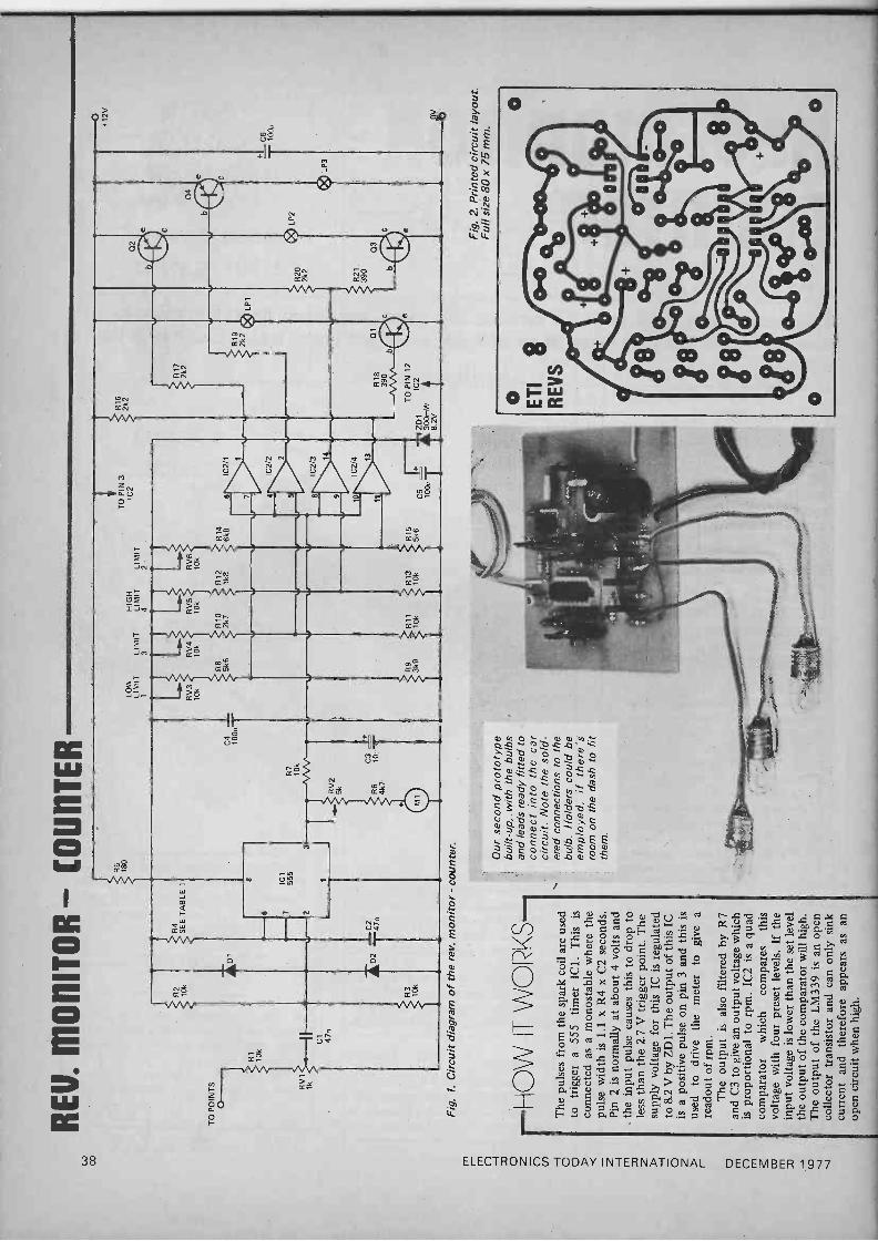
This design uses light bulbs to indicate the upper and lower limits of ideal rev ranges. Details are also given of an optional analogue tacho which can easily be
added.
WE HAVE HAD many requests to publish the design of a digital tacho- meter for use in cars. However, a
couple of factors make this less than a practical proposition.
The most important drawback is
difficulty of reading the digital display. Many cars can rev out over a 5000 rpm range in less than two seconds; even with 100 rpm resolution this would have the second digit changing every 0.04 seconds.
Additionally, the simplest design principle - counting the number of pulses from the distributor over a
period of time - would not offer acceptable resolution for a reasonable sampling rate. On a four -cylinder car, a two -digit readout, i.e. 100 rpm resolution, calls for a sampling time of 0.3 sec, while 3 sec is needed for a
three -digit readout. Analogue meters are easier to read
but may be a little sluggish with cars which can rev out quickly in first gear. We therefore decided to design an
analogue tacho and add three indicator lamps to give an instant indication or warning of engine speed. One of these is
on below a set rpm indicating that the motor is below the ideal minimum, a
second which is on between certain limits indicating the working range of the engine and the third comes on above a set rpm indicating too high an engine speed. All the limits are adjustable and by overlapping the limits five bands of engine speed can be indicated.
Where the vehicle is already fitted with a tacho, or one is not wanted, the' lights can be used by themselves. This reduces the cost considerably, while the lights still give an indication of engine speeds and when to change gear.
ELECTRONICS TODAY INTERNATIONAL -
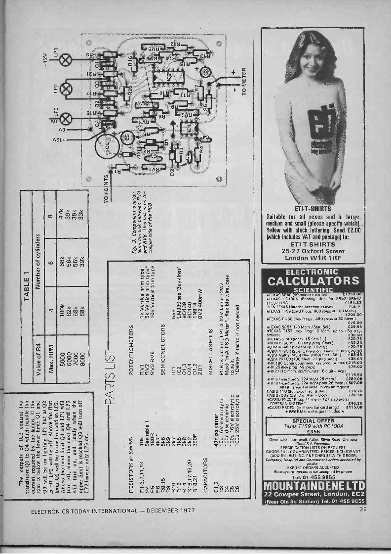
Construction The electronics can be assembled on the printed circuit board with the aid of the overlay in Fig 3. Due to the number of components, the use of the printed circuit board is recommen- ded. The value of R4 should be selected from Table 1.
The mechanical arrangment for the lights and meter we have left to the constructor as variations in style required make it difficult to give any details.
Adjustment The potentiometer RV1 should be adjusted to give stable readings over the entire rpm range. Calibration of the meter is done by RV2 and this should
DECEMBER 1977
be done against a known instrument. The lights are adjusted by RV3, RV6, RV4 and RV5 (from the lowest to the highest limit) to whatever levels are required.
BUY L I\LS
All the components for this project should be available from most of the larger component suppliers advertising in this issue.
The cost of this project, excluding meter and case, is approximately £6.50.
37
ó ÚQ
á
tI
H
> JN. f20 N M ¡
2~
77: J
° -
ó0
14
o
K,
i L 0 C .. O p U . cd ,.= 1:1 4 .0 O ,L, !~ X S'.
u Li Q .+ .0 ß. ..4 > bg U -f. cd
N.< ---'N í°)- ó ..%, O ÿ > > 3 á ó `
F ó b C on ÿ ° p a ::> ó i (v ,-;3N>aó ` ó roº U3oro
m ó v a. . +~ / ' r °U °:v áM +~ °' óN °'a>i o p á
?4 .o X5, p U p, a > U o
.- g M c`i b O.-. V p OA y p A. °e
w U y cd m ac óy, , y.Y o R ó p. áº'> ;
p '«. x O ° 5 A. ... , a E 1 cC p .ti0
ÿ o ro o 3 ° >,p wH ge . o Fi p U o ^ G + .-r N ^ óv . s 3 0 .4ÿ °
' ,x á,ÿ,-Q 9 º LL .> b ó ° b 3
O - . b ' O . y ; ,.., C
7 OD 3 Q O O 5 M R. N O .p7
=' ',Fti,,
h N. ... a. N L1 0 0 0 ¢, b0 .,+ 5 O Ú 27 17 H F
.... ° .-p. O ,
o ó áe o y a ó ó á.c.0 ó á. E. °o.ä ti..A,~ m.4 °>. ..E2°Uo
38 ELECTRONICS TODAY INTERNATIONAL - DECEMBER 1977
> N +
-YYYY .1" M M
Cl
V)
a)
_
t) Y Y Y Y
I- c s. a) .0
CO CO CO 0) CO CO LO Cl
W J d Z 4 I-
e NCOcO co coco
e cc
O a)
a. p 0 0 0 OOOO
O Te
ß g Lt) CO I co
>
.C.C.0 C N yN0.,. cn cu
w0 ... . cc, a L 0.. 3 .d +
___et)4.2 cla)a ,--1 1:3 C Ñ ch a,.a-1mÿ ó tu r>,3 P-. V .aQ Ó--, Xrod L: ..3 w aä Sb O
w Cl 4..4" T O ' O .O ,.. ' a) .0 t7. ° a p en y ÿ ,C ~ c) 4 h O T7.= . m .--i .-+ y a+ ^.O a) .-+ N
N F. '-Ti y'3 ó3ACóó 0 O : p O .-+ a0 ó d Áá 3 e c'.E p O N. -.w" ....., 5,-
1.> + +' ,,.,e a w ÿ.-. ,.ÿ g- 3wa> ° ? H ti M 0.... p rC. CLá 0'.:áQ3a
* ° a)m°. CI O. T ÑY Ç vmi
o E E
E N0 L ., 7--.. + m N _
Ta m o cu
U U 'i ÿ p Ó- a3) M =aaN>Y Md M - X a
dYO LnOZ> > 2 - LO e- LnJCOOO a- CO .' a) *c M ++
L-) O â C a) J2 =)
O C 'CD .0
u ÑrE;
LL a7
> O J aE CCU w ,: NM MVNs.-
lA m X «,,Ñ »> U m p
a 4 CC* CC
¿C) O ÑOOYYYYYIT a-cn.-CrLnMNCONM
CO
N M Ñ CC
O
V) N a- N M
W eLn COCO OONtCOW CC OC CC CC CC CC CC OC OC CC CC CC
N M V ln CD 00000
ELECTRONICS TODAY INTERNATIONAL - DECEMBER 1977
TI T-SHIRTS
Suitable for all sexes and in large, medium and small (please specify which). ,
Yellow with black lettering. Send £2.00 which includes VAT and postage) to:
ETI T-SHIRTS 25-27 Oxford Street
London W 1 R 1 R F
ELECTRONIC CALCULATORS
SCIENTIFIC *TEXAS SR60 (40 memory printer . £ . .) r
*TEXAS PC100A (Printing Unit for SR52/SR56/ T159/T158 £161.22 HP & TEXAS Libraries Accessories avail ... P.A.P. *TEXAS TI -59 (Card Progs. 960 steps of 100 Mem.)
£ 205.00 *TEXAS T1-58 (Key Progs., 480 steps or 60 Mem.)
£74.00 *TEXAS SR51 II (3 Mem./Stat. Sci.) £29.95 *TEXAS T157 (Key Progr. 8 Mem. up to 150 Key- strokes) £36.50 *TEXAS SR40 (Mem. 15 Sets [ ] £20.75 *NOVUS 6035 (100 step prog. Stats.) £32.30 *CBM 4148R (Scient-Exp. 10 dig.) £20.75
' *CBM 4190R (Scient. Pre-prog. 14-dig./EXP) £26.30 *CBM Maths (M55) Nov. (N60) Stat. (S61) £63.43 *CBM PR100 (100 Mem. 72 step prog.) . . £35.00 *H P.19C (continuous mem. key prog. printer)£219-00 *HP 25 (key prog. 49 steps) £79.00 *HP27 (10 mem. sci/fin./stat. 8 -digit+ exp.) . . .
£119.50 *HP 67 (card prog. 224 steps 26 mem.) . £289.00 *HP 97 (card prog. 224 steps print 26 mem.)£507.00
All HP range available. Prices on request CASIO 110 (Sci. Exp. Frac. & Dig.) . £16'.75 CASIO/CO2 (Cal. Dig. Alarm Clock) £31.50 *CASIO FX201 P (sci. 11 mem: 127 step prog.) .. "FORTRAN SYSTEM" £46.25 *CASIO PROFXI (as above but card prog.) £115.00
*FREE Mains charger included *
SPECIAL OFFER Texas T / 59 with PC100A
£356 / Other calculators avail. Adler, Silver Read, Olympia
(Send S.A. Envelope) SPECIFICATION LISTS ON REQUEST
GOODS FULLY GUARANTEED. PRICES INCLUDE VAT (ADD 8%) BUT INC. P&P CHEQUE WITH ORDER.
Company, Hospital and Government orders accepted by phone.
EXPORT ORDERS ACCEPTED Barclaycard, Access order accepted by phone
Tel. 01-455 9855
MOUNTAINDENE LTD 22 Cowper Street, London, EC2 (Near Old St. -Station) Tel. 01-455 9855
39

CHESS CHALLENGER HAVE YOU EVER wanted to pit your wits against a computer? With Fidelity Elec- tronics' new Chess Challenger you can have your chance. This is an 8080 based micro- computer- programmed to play you at chess, neatly packaged into an instrument no larger than this copy of ETI and about 40 mm thick. But beware! This machine is no light- weight toy. Though it does not play at Grand Master level, it will give an average player a good game, beating him 30-80% of the time. All of us at ETI found it wise to take it very seriously. There is a great temptation when first playing it to see if it will "notice" your exposed pawn line, with rather devastating results. Give an inch and it will take your queen!
The Challenger is based around the 8080a microcomputer with a 16k ROM program and 512 bytes of RAM. The program checks up to" 20,000 possible moves, not just to see if you can take one of its pieces (or vice versa), but also for positional advantage. It does all this in just under three seconds, which can be very humiliating after you have just sweated for quarter of an hour over your move! In fact it has not been unusual to find a member of ETI's staff during lunch, quietly telling our review machine most unlikely things about its ancestry after it caught him in a neat knight's fork!
The game itself is played by setting out the pieces on the chess board marked on the computer, making a move and then entering this via a keyboard. The move is entered using an international style: first the square from which the piece is moved and then the square to which the piece is moved. This is shown on two pairs of LEDs. Then the enter key is pressed, or, if you suddenly realise you have left your queen uncovered, you can press the clear key and start the move again.
After a second or two the LEDs will light up again, this time telling you from which and to which square the challenger is mov- ing. You then move the computer's piece as directed - and start sweating! You move the pieces on the chess board because the machine is a much superior being and can remember exactly where all the pieces are!
We found, that at least to start with, it is important to check each move very carefully and preferably to write it down exactly as they occur on the LEDs. It is all too easy to punch in the wrong coding or misread the machine's move, because you expect it to move one way and instead of a rather similar move, five moves later it check -mates you with a pawn that you thought was a rook,
ETI Reader Offer: Get your Chess Challenger for E115 inc!
r
Originally we were only going to review the Chess Challenger but it was such a hit with ETI's staff that we decided to arrange an offer.
and you curse and swear about machines that not only play chess but cheat to boot! So careful checking and a complete record is good for your mental balance until you are used to the machine.
The machine always plays black, but it is quite easy to make the first move by cheat- ing. You see the machine always plays fair but will accept illegal moves on your part (obviously it has a naive trust in human honesty). So that if you start by moving a piece from the square it is on to the same square it will accept this and carry on. If you wish to castle there is a "double -move" button that allows you to do this. This button is also very useful for taking back a move, as the machine will allow you to play its pieces as well as your own.
We have all had hours of fun, amusement, sweat, tears and humiliation with the Chess Challenger. We can only say that all our chess has certainly improved since we started playing it and although it has only one level of expertise, you can expect it to give you a hard time for a long while and a good game for many years to come. So for
anyone who wants to improve their game or just wishes to wile away some time we can thoroughly recommend it.
When your game improves so that the challenge is reduced, you can even send it back to the British distributors with a cheque and have two further levels of skill incorpo- rated - the top level being of an ex- traordinarily high standard.
We have had such fun with the Chess Challenger that we've organised a special offer for ETI readers only. Currently the unit is available at about the £140 mark and is selling well by all accounts but purchasing the unit from us means you pay just £115 including VAT and insured carriage.
Since even our bargain price of £115 is a lot of money, a Chess Challenger will be avail- able for playing with at our offices at 25-27 Oxford Street, London W1 (very close to Tottenham Court Road Underground) until the end of November on weekdays between. 11.00am and 3.00pm (we must limit this to five visitors at a time and five minutes play per person if there are others waiting for obvious reasons).
To: Chess Challenger Offer ETI Magazine 25-27 Oxford Street London W1 R 1 RF
Please find enclosed my payment of £115.00 for a Chess Challenger
Name
Address
Offer closes December 31st, 1977. Please allow 28 days for delivery
ELECTRONICS TODAY INTERNATIONAL - DECEMBER 1 977
1
43

This month we present a low cost, high quality design from
Crofton Electronics for a
CCTV CAMERA UNTIL RECENTLY THE appeal of a CCTV camera was limited to a large extent by two factors.
The first being that the only video recorders available were very expensive professional, or semi-professional, machines that were beyond the reach of all but the most affluent of amateurs. This situation was a severe drawback as far as many potential users were concerned because, in most applications, some means of preserving a record of the camera's output is an essential part of the appeal of a CCTV system
Attitude Of Mind The second reason that CCTV cameras have not been more popular in the past can be attributed to an attitude of mind. Thus, until now most people have viewed their TV set, in both the literal and mental sense, as merely a means of receiving picture and sound signals pumped out by the TV stations under the guise of entertainment.
Today, however, people are beginning to recognise the vast number of additional uses to which "The Box" can be put. TV Games, Teletext and Viewdata have shown just what a versatile creature the TV set is.
The realization of the TV's. potential coupled with today's crop of low-cost video recorders, means that a CCTV camera should have a far wider appeal today than would have been the case a few years ago.
Before we move on to describe the
design and construction of the camera in detail we shall briefly explain just how a TV picture is produced.
Picture Parlance
The picture is formed by arranging for an electron beam to scan the phosphor coated inside surface of a TV tube in a series of horizontal lines.
The electron beam upon striking the screen causes the phosphor to emit light from the screen's surface - the amount of light emitted depending upon the electron beam current at that instant, which in turn will depend upon the video signal level.
The scanning action referred to above starts at the top left-hand corner of the screen. Each scan line then moves across the screen from left to right and slants slightly downwards towards the right. At the end of a line the beam returns rapidly to the left-hand side of the screen. This action is called line flyback.
When the screen has been scanned in this manner the beam is positioned at the bottom right-hand side of the screen. From here it is
Fig._ 1. Diagramatic representation of the scanning action of a TV set.
LINE SCAN
_ - - - - FLYBACK --4--------
returned rapidly to its starting position - the action of frame flyback.
In order that the human eye perceives the resultant display as a continuous, flicker free, picture, it is necessary for fifty complete scans of the screen to take place every second.
HOW IT WOR zS--J In essence the vidicon comprises a light sensitive element and an electron gun housed in an evacuated glass tube.
Light from the scene to be televised is imaged onto the Vidicon's photoconducti- ve target by the camera's lens. The function of the Vidicon is to convert this image into an electrical signal suitable for processing by the camera electronics.
The construction of a typical vidicon can be seen in Fig 2.
The light sensitive element is comprised of a transparent conductive coating deposited on the inner surface of the tube faceplate. This layer is coated with a thin film of photo -conductive material.
An external target ring is fitted to the outer edge of the face plate and is connected to one side of the photocon- ductive coating via the transparent conductive layer.
The other side of the photo -conductive layer is scanned by a low velocity electron beam.
The photo -conductive layer may be regarded as being composed of many discrete capacitors each one insulated from its neighbour, but each having one of its plates connected to the target ring via the conductive coating. The other plate of each capacitor is left floating.
With the target connected to a positive potential, the electron beam is made to scan all the floating capacitors. This initiates electron flow that charges up all of the individual capacitors.
Due to the photo -conductive properties of these capacitors, their individual
i 46 ELECTRONICS TODAY INTERNATIONAL - DECEMBER 1977

With a 625 -line standard, if we were to produce fifty 625 -line pictures every second the bandwidth required in the video amplifier stages would be of the order of 12 MHz.
In order to reduce the bandwidth requirements to a more manageable level a system of interlaced scanning is used.
In this system the whole picture is covered by only half the number of lines. Thus in the 625 -line system two 'frames' of 312.5 lines make up one complete 625 -line 'field' every 1/25 second. This effectively halves the bandwidth requirement while still providing high definition, flicker -free, pictures.
Camera Conventions The TV camera uses a similar system of scanning, except that in this case the TV screen's phosphor layer is replaced by a photo sensitive layer onto which the scene to be televised has been focused.
In order to ensure that the picture produced on the TV screen is "intelligent" it is necessary to ensure that the scanning action of the camera and TV set are in step -or in sync (synchronisation).
To achieve this, sync pulses are
added to the video signal at the camera and used in the TV set to synchronise scanning action.
Two types of sync pulses are required. First, line sync pulses which occur at the end of every line
and second, frame pulses to indicate the end of a frame.
The TV camera also produces signals that ensure that the TV's display is blanked (turned off) during the line and frame flyback periods.
Oh So Discrete A look at the circuit diagram will
THE VIDICO\ discharge times will depend upon their illumination which determines their internal resistance. The greater the illumination, the lower the internal resistance and the faster the discharge time.
Each subsequent scanning of the capacitors will restore the individual charge to maximum, the amount of charge required to do so being directly related to the illumination of the cell between scan, times.
This varying signal , as the electron scans all the capacitors, is sampled across a load
Fig. 2 Construction of a typical vidicon tube is shown to the right.
TRANSPARENT CONDUCTIVE COATING
GLASS FACEPLATE
and used as the video signal. The electron beam is generated by the
vidicon electron gun (comprising cathode, control grid and anode1). It is focused into a fine spot on the rear surface of the target in order to perform the action described above.
The mesh anode is a fine wire mesh placed closely to and parallel with the photo -sensitive layer, to slow the electron beam down (it is connected to a positive potential).
This reduces secondary emission and improves resolution.
MESH ANODE
PHOTOCONDUCTIVE LAYER
TARGET CONNECTION
FOCUS COIL
/
ELECTRONICS TODAY INTERNATIONAL - DECEMBER 1977
reveal a cornucopia of transistors and diodes with a famine of ICs. This may prompt some of you to ask why 'we did not make more use of ICs in the video stages, and perhaps in the line and field sections.
The reasons for not using ICs in these stages are that the camera would have been no cheaper, no more reliable, more expensive to repair if things went wrong and probably would never have been finished as most of the ICs would probably have been very difficult to get hold of.
We think our discrete design was the best bet.
In Camera
Construction of the camera is
simplified by the fact that most of the components are mounted on a single PCB.
Mount the components on this board according to the overlay shown in Fig 6. Pay particular attention to the orientation of all polarized capacitors and consult the semiconductor lead -outs shown before soldering these devices in place.
Note that the junction of R 1 1 and Q4's base should be formed by cropping Q4's base as close to the case of this device as is possible and soldering R 1 1 directly to the cropped lead.
Note also that diode D11 is a
temperature compensating device and should be mounted in close proximity to Q28.
The board'is of compact design as can be seen from our photographs and care should be taken to ensure that a neat, well finished, board is produced.
C44 is not mounted on the PCB and should be clamped to the
47

CCTV CAMERA
TO V1/T C2 4n7 Q1
IR 1
3M3
Cl T 2n7
R40 10M
R42 10M
Q12
R41 330k
C19 lu
D2
R3 tC4 330R 47u
C3 100u
02
R45 47k
013 R47 10k
+ D3 +
C18 T20 47u 10u
240 VAC
O m FS1 SW1
R8 47R
1 C43 470n
Q27
RV9 1M
R17 15k R18
1k
C49 in
R88 6k8
TO V1/G2
TO V1/A R76 1M5
R83 470k
RV8 1M
R13 Q3 680R
R11 330R
07,8,9,10
2200u
R86 6k8
TO V1/K
R77 470k
ZD1 150V 1.3W
N
R85 100k
L2 2000 t
C27 47u +,
INPUT
.1- C37 I 22n C38 220n
-i TO V1/G
R24 3k9
R25 1k8
C11
10u
R57 470R
R_
iC
Q 1 7
OUTPUT R79 82R
COMMON + ZD4
6V2
C46 C471'3W 100n T100u
48 ELECTRONICS TODAY INTERNATIONAL - DECEMBER 1977

.'2
.:On
R 26 4k7 R28
1k5
©Q8
C13 10u
RV2 5k
R27 1k
R 31
4 R7
C14 +10u
R32 680k
R33 560k R36
470R
R37 56R
011
R 39
75R
R38 470R
C17 33u
R58 'k5 R60
12k
Q18
T C30 47n
R61 6k8
R 64 1k5
R62 12k
019 020
igR63 12k
R65 12k
021
R68 680R
Q24
C32 150n
0 R67 6k8
C33 10n
R69 8R2
R73 10k
R72 1k
025
026
R74 470R +
C35 68u
C36 220u
Q90G9,
L 3/FR
R75 100R
RV7 100 R
RV 1
500R R80 390R
D11
R81 1k8
R82 30R
028
L3/FOC
NOTES: ClI IS 7815
Q1,8 ARE 2N5245 02-7,10,14 16-23,26 ARE BC1825 09,11,24, 25 ARE BCY72
012 IS 8E336 013,15,27 ARE BFY50 028 IS 2N2905A D1,2,3,5
11 ARE 1N914 D4 IS BY206 D6,12 ARE 1N4006 D7,8,9,10 ARE 1N4004
L3 / FR = Frame scan coil
L3/L = Line scan coil
L3/FOC = Focus coil
5 - TO V1/H TO V1/H
NOT TO SCALE
TARGE T
L K pin 7
pini H
pin 8
I
G1 G2 pin 2 pin 5
The full. circuit diagram of the camera together with the pin designations of the vidicon tube and base connection diagrams for the various semiconductor devices used in the design.
A pin 6
V1
SHORT INDEX PIN
M pin 3
V1 BASE
5
6
ELECTRONICS TODAY INTERNATIONAL -,DECEMBER 1977
BASE LEADOUTS
BC182B
BCY72,13F336
SOURCE
DRAIN
2N5245
B F Y50,2 N 2905A
ALL VIEWED FROM BELOW
GATE
53

CCTV CAMERA
^B0
C47+
V1/H
V1/G1
V1 /AN
V1/G2 V1/NI
-20 -20 Cl 0/P V1/LL3/LWHITE C47 -Ve BLUE
24 -.C ..
rUn v ... .,..I
^350
camera's chassis. IC1 should also be mounted on the chassis, taking care that there is a good thermal contact between the regulator and chassis as
D11'¡
V1/K L3/FR (YELLOW)
r
-,-.r (,)16U --i 555 )--
,. C29 ...
L3/FOC VIDEO L3/L1 BROWN OUTPUT RED
--{ R 81 F
.-11388(- t
L3/FR GREEN
YRVf ` 074 i125
P V4
Fig. 6. Component overlay of CCTV camera.
the device dissipates a fair amount of heat in normal operation.
You will notice that we do not give any constructional details of the
RESISTORS (All resistors 1/4W 5% unless otherwise stated)
R1 R2,49 R3,11 R4 R5,7,61,67,87,88 R6,10,26,29 R8,20 R9,14,18,2 7,34,48, 72 R12 R 13,68 R15,31 R16 R17 R19,56 R21 R22,28,58,64 R23 R24 R25,81 R30 R32 R33 R35,36,43,46,57,74 R37 R38 R39 R40,42 R41 R44 R45 R47,59,73 R50 R51 R52 R53 R54 R55
3M3 /2W 10% 150k 330R 5k6 6k8 4k7 47R 1k 22R 680R 4R7 75k 15k 2k2 120R 1 k5 1k8 '/2W 5% 3k9 1k8 3 k3 680k 560k 470R 56R 470R 1/2W 5% 75R 10M '/4W 10% 330k hW 5% 33k 47k 10k 12R /2W 5% 27k 220R 150R 270R 1/2W 5% 68k
%W 5%
V1/T
scan /focus coil (L3) or of coils L1
and L2. This is because we feel it would be almost impossible for the home constructor to produce items of
PARTS LIST R60,62,63,65 R66 R69 R70 R71 R75 R76 R 77,83 R 78 R79 R80 R82 R84 R85 R86
12k 2k7 8R2 270R 2k4 100R 1M5 470k 120k 82R 390R 30R 5M6 100k 6k8
YzW 5%
'hW 5% 7W 5%
'/2W 5% /4W 10%
hW 5%
C31,38,45 220n C32 150n C33 10n C34 22u C35 68u C36 220u C37 22n C39 100n C40,41 470n C42 10u C43 470n C44 2200u C48 8u C49 1n
250 V Polyester 250 V Polyester 250 V Polyester 25 V Electrolytic 16 V Electrolytic 16 V Electrolytic 250 V Polyester 400 V Polyester 400 V Polyester 450 V Electrolytic 250 V Polyester 35 V Electrolytic 150 V Electrolytic 100 V Ceramic
POTENTIOMETERS CAPACITORS
RV1,2,4 5k lin
C1,29 2n7 125 V Polystyrene RV3 1k lin
C2 4n7 160 V Polystyrene RV5,6,11 500R lin
C3,47 100u 25 V Electrolytic RV7 100R lin C4,5,9,25 47u 25 V Electrolytic R V8,9,10 1M lin
C6 470p 63 V Ceramic C7 150p 160 V Polystyrene C8,13,14 10u 20 V Tantalum SEMICONDUCTORS C10 180p 63 V Ceramic 01,8 2N5245 C11,15,20 10u 25 V Electrolytic Q2-7,10,14 C12 330n 250V Polyester 16-23,26 6C1826 C16 22p 160 V Polystyrene 09,11,24,25 BCY72 C17 33u 16 V Electrolytic Q12 BF336 C18 47u 10V Electrolytic 013,15,27 BFY50 C19 lu 35 V Tantalum Q28 2N2905A C21 2u2 15V Tantalum D1,2,3,5,11 1N914 C22 10n 160 V Polystyrene D4 BY206 C23 3n3 160 V Polystyrene D6,12 1N4006 C24,46 100n 250 V Polyester D7,8,9,10 1N4004 C26 4n7 160 V Polystyrene ZD1 150V1.3W C27 47u 10V Electrolytic ZD2 200V 1.3 W C28 680p 100 V Ceramic ZD3 100V 1.3 W C30 47n 10 V Polyester ZD4 6V2 1.3. W
54 ELECTRONICS TODAY INTERNATIONAL - DECEMBER 1977

3UY LI \ES A complete kit of parts for this project is available from Crofton Electronics at 35, Grosvenor Road, Twickenham, Middlesex.
Crofton are also sole suppliers of the non-standard components used in the camera and will supply these items individually if required.
this type that were capable of giving acceptable performance.
We have arranged for these coils to be available ready built, see Buy Lines.
CAMERA When construction of the camera is complete it is wise to carefully check that all is in order, a wiring error could prove expensive. It is also worth bearing in mind that there are some high voltages present at certain points in the circuit so it is not wise to prod around inside the camera with quite the same gay abandon that one might with a 9 V transistor radio.
When reasonably confident that everything is as it should be set up the eleven preset potentiometers to the positions shown in Table 1 and set the beam alignment magnets at
VIDICON
Type 9677 or similar (95 mA Heater)
LENS
Fujinon CCT V fixed Focus lens type CF25C
SWITCH
Single pole on/off slide
TRANSFORMER
240 V - 350-0-80 plus 20 V (see Buy Lines)
INDUCTORS
L1 Line oscillator inductor L2 Line Load inductor L3 KV 9P/G Scan/Focus Coil (See Buy Lines for the above inductors)
CASE
See Buy Lines.
MISCELLANEOUS
Grommet, 3 -Core Mains Flex, 1/" Plastic P Clip, '4" Capacitor Clamp, Lens and scan coil mountings, Base Connector for V1, Nuts, Bolts, Washers, Ribbon wire, Screened cable, 250 mA fuse plus 20 mm fuse holder, Neon, Video output socket.
Fig. 7. Full size foil pattern for CCTV camera. Note copyright design is held by Crofton and ETI.
ELECTRONICS TODAY INTERNATIONAL - DECEMBER 1977 55
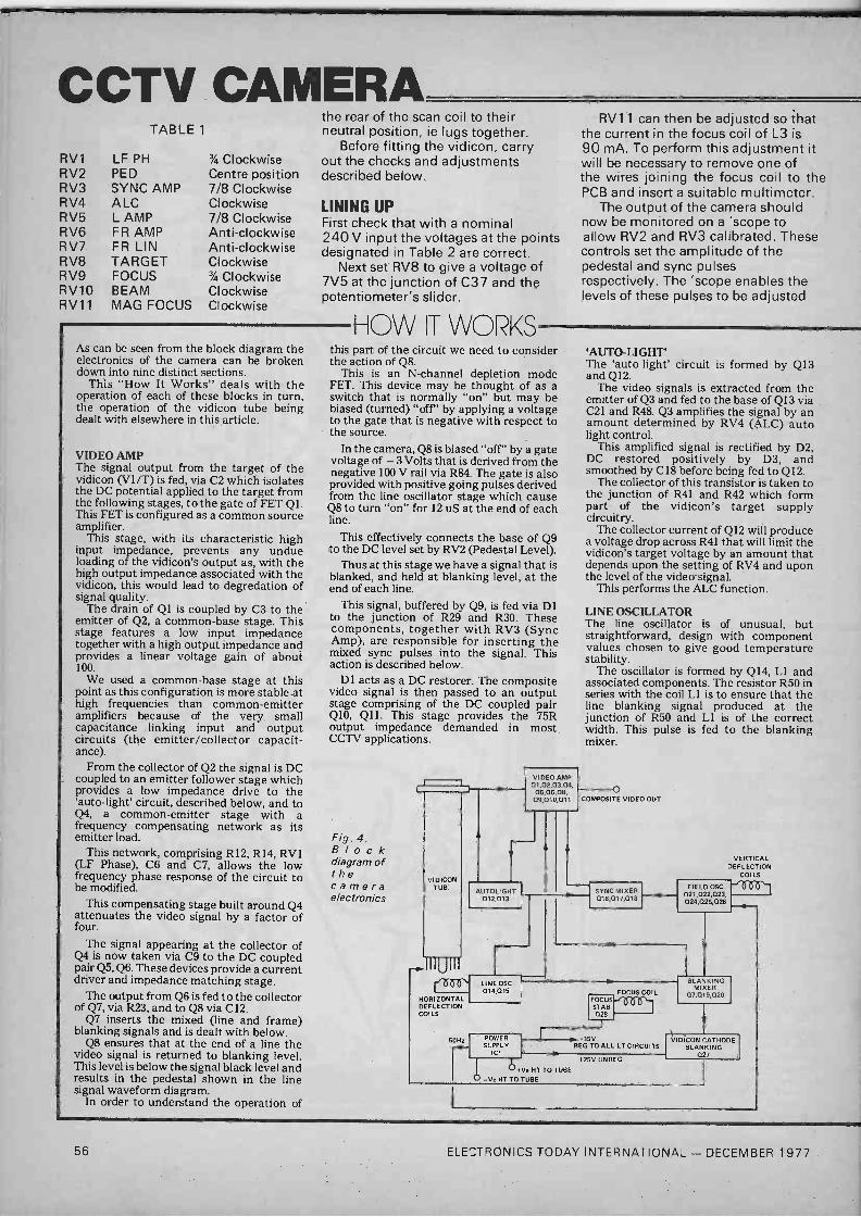
CCTV CAMERA RV1 RV2 RV3 RV4 RV5 RV6 RV7 RV8 RV9 RV10 RV11
TABLE 1
LF PH PED SYNC AMP ALC L AMP FR AMP FR LIN TARGET FOCUS BEAM MAG FOCUS
% Clockwise Centre position 7/8 Clockwise Clockwise 7/8 Clockwise Anti -clockwise Anti -clockwise Clockwise 3/4 Clockwise Clockwise Clockwise
the rear of the scan coil to their neutral position, ie lugs together.
Before fitting the vidicon, carry out the checks and adjustments described below.
LINING UP First check that with a nominal 240 V input the voltages at the points designated in Table 2 are correct.
Next set RV8 to give a voltage of 7V5 at the junction of C37 and the potentiometer's slider.
As can be seen from the block diagram the electronics of the camera can be broken down into nine distinct sections.
This "How It Works" deals with the operation of each of these blocks in turn, the operation of the vidicon tube being dealt with elsewhere in this article.
VIDEO AMP The signal output from the target of the vidicon (V1/T) is fed, via C2 which isolates the DC potential applied to the target from the following stages, to the gate of FET Ql. This FET is configured as a common source amplifier.
This stage, with its characteristic high input impedance, prevents any undue loading of the vidicon's output as, with the high output impedance associated with the vidicon, this would lead to degredation of signal quality.
The drain of Q1 is coupled by C3 to the emitter of Q2, a common -base stage. This stage features a low input impedance together with a high output impedance and provides a linear voltage gain of about 100.
We used a common -base stage at this point as this configuration is more stable at high frequencies than common -emitter amplifiers because of the very small capacitance linking input and output circuits (the emitter/collector capacit- ance).
From the collector of Q2 the signal is DC coupled to an emitter follower stage which provides a low impedance drive to the `auto -light' circuit, described below, and to Q4, a common -emitter stage with a frequency compensating network as its emitter load.
This network, comprising R12, R14, RV1 (LF Phase), C6 and C7, allows the low frequency phase response of the circuit to be modified.
This compensating stage built around Q4 attenuates the video signal by a factor of four.
The signal appearing at the collector of Q4 is now taken via C9 to the DC coupled pair Q5, Q6. These devices provide a current driver and impedance matching stage.
The output from Q6 is fed to the collector of Q7, via R23, and to Q8 via C12.
Q7 inserts the mixed (line and frame) blanking signals and is dealt with below.
Q8 ensures that at the end of a line the video signal is returned to blanking level. This level is below the signal black level and results in the pedestal shown in the line signal waveform diagram.
In order to understand the operation of
HOW IT WOR <S
RV11 can then be adjusted so that the current in the focus coil of L3 is 90 mA. To perform this adjustment it will be necessary to remove one of the wires joining the focus coil to the PCB and insert a suitable multimeter.
The output of the camera should now be monitored on a 'scope to allow RV2 and RV3 calibrated. These controls set the amplitude of the pedestal and sync pulses respectively. The 'scope enables the levels of these pulses to be adjusted
this part of the circuit we need to consider the action of Q8.
This is an N -channel depletion mode FET. This device may be thought of as a switch that is normally "on" but may be biased (turned) "off"' by applying a voltage to the gate that is negative with respect to the source.
In the camera, Q8 is biased "off" by a gate voltage of -3 Volts that is derived from the negative 100 V rail via R84. The gate is also provided with positive going pulses derived from the line oscillator stage which cause Q8 to turn "on" for 12 uS at the end of each line.
This effectively connects the base of Q9 to the DC level set by RV2 (Pedestal Level).
Thus at this stage we have a signal that is blanked, and held at blanking level, at the end of each line.
This signal, buffered by Q9, is fed via D1 to the junction of R29 and R30. These components, together with RV3 (Sync Amp), are responsible for inserting the mixed sync pulses into the signal. This action is described below.
Dl acts as a DC restorer. The composite video signal is then passed to an output stage comprising of the DC coupled pair Q10, Q11. This stage provides the 75R output impedance demanded in most CCTV applications.
Fig. 4. Block diagram of the camera electronics
VIDICON TUB"
UTO LIGHT 012,013
VIDEO AMP 01,02,03,04
05,06,08, 09,010,011
`AUTO -LIGHT' The `auto -light' circuit is formed by Q13 and Q12.
The video signals is extracted from the emitter of Q3 and fed to the base of Q13 via C21 and R48. Q3 amplifies the signal by an amount determined by RV4 (ALC) auto light control.
This amplified signal is rectified by D2, DC restored positively by D3, and smoothed by C18 before being fed to Q12.
The collector of this transistor is taken to the junction of R41 and R42 which form part of the vidicon's target supply circuitry.
The collector current of Q12 will produce a voltage drop across R41 that will limit the vidicon's target voltage by an amount that depends upon the setting of RV4 and upon the level of the video signal.
This performs the ALC function.
LINE OSCILLATOR The line oscillator is of unusual, but straightforward, design with component values chosen to give good temperature stability.
The oscillator is formed by Q14, L1 and associated components. The resistor R50 in series with the coil Ll is to ensure that the line blanking signal produced at the junction of R50 and L1 is of the correct width. This pulse is fed to the blanking mixer.
o COMPOSITE VIDEO OUT
IIIUIII room
HORIZONTAL DEFLECTION COI LS
5011,
LIN OSC 014 015
SYNC MIXER 016,017,018
VERTICAL DEFLECTION
COILS
FIELD OSC 021,022,023, 024,025,026
POWER SUPPLY
ICI
FOCUS COIL
STAB 026
115V REG TO ALL LT CIRCUITS
BLANKING MIXER
07,019,020
v+Ve HT TO TUBE
-Ve HT TO TUBE
+25V UNREG
VIDICON CATHODE BLANKING
027
56 ELECTRONICS TODAY INTERNATIONAL - DECEMBER 1977

TABLE 2
D6 Cathode +450 V ZD1 Cathode +350 V D12 Anode -130 ZD3 Anode -100 V IC1 Input 25 V IC2 Output 15V
Voltages at the above points should be within 10% of the stated values.
until they correspond with those shown in Fig 5. During this operation the camera's output should be terminated with a 75R load.
At this stage connect the camera to a monitor or, via a modulator, to a domestic TV set.
L1 can now be adjusted until the display on the TV screen stabilizes to a plain raster. By the way, do not adjust L1's core with a screwdriver as this is certain to break the core - we speak from experience.
The output of the line oscillator is taken from the collector of Q4 and passed via a pulse shaping network, R53 and C25, to the base of Q15.
The OV5 pulse at this point produces a sinusoidal pulse of some 60 V at its collector. The collector load is formed by L2 (10 mH) together with R54 and RV5 (Line Amp). The latter allows adjustment of line width.
This sinusoidal pulse, when applied to the scan coils, L3/L, produces the required sawtooth current waveform.
Diode D4 is included to prevent negative overshoots of the waveform damaging Q15.
The line scan signal applied to L3/L is also fed to the sync mixing stage and to gate of Q8 which ensures the signal is maintained at blanking level at the end of a line as described above.
FIELD OSCILLATOR The field scan waveform is formed by processing of a 50 Hz signal derived from the low tension winding of the mains transformer.
From the transformer, after DC isolation provided by C43, the 50 Hz waveform is passed, via R67, to the base of Q22.
Q22 is an overdriven amplifier and, with the pulse shaping provided by R67, C32 and D5, produces a square wave at its output. This square wave, after inversion, provides
Fig. 5. Waveform of typical video signal.
END OF FIELD
FIELD BLANKING PERIOD 1.28mS
VIDEO SIGNAL
LINE BLANKING PERIOD -
I-- LINE TIME 64uS
THE ELECTRO\ICS
If all the above is satisfactory the vidicon may be fitted. The vidicon is fitted from the front of camera and should be inserted to its full extent within the focus coil assembly. The tube should be aligned so that the short index pin of the base is at nine o'clock when viewed from the rear.
Tube installation is completed by tightening the tube clamp, cleaning the tube face with some tissue and fitting the lens mount to the front of the camera.
the field syn signal which is taken to the sync mixing stage.
The output from Q22 is also taken, via C31, to Q21. This transistor shapes the Q22 output to provide the field blanking signal. This in turn is fed to the blanking mixer.
This same signal is taken via R63 to the base of Q23 which forms part of the ramp generator that provides the field scan waveform.
The rest of the ramp generator is formed by Q24, a constant current generator. This presents a constant charge current to C34 and thus the voltage on this capacitor will increase in a linear fashion. This process will continue until Q23 conducts in response to the frame blanking signal ap- plied to its base.
This discharges the capacitor rapidly, via current limit resistor R69, whereupon the cycle begins again.
The value of constant current supplied by Q24 can be adjusted by RV6 (Frame Amp). This control provides the field amplitude control.
The ramp waveform is taken to a current driver stage, Q25, and then to a voltage driver, Q26. This drives the frame scan coils, L3/FR, via C35.
RV7 (Frame Lin.) and C36 provide adjustment of the frame lineiarity.
BLANKING MIXER The blanking mixer is formed by a collector
START OF NEXT FIELD
y
x
o a
o
S
PEDESTAL
}
LINE SYNC PULSE
mixer circuit comprising Q19 and Q20. The line and frame pulses are applied to
the bases of Q19 and Q20 respectively and the signal appearing in the common load resistor, R61, is the mixed blanking waveform.
This signal is applied to the emitter of Q7 and, after shaping, to the base of Q27.
Q7, biased by R24 and R25 with C11 decoupling, blanks the video signal from Q6 in response to the output from the blanking mixer.
VIDICON CATHODE BLANKING Q27 provides cathode blanking of the vidicon. This transistor is fed from the 25 V unstabilised rail in order to ensure that the blanking pulse is of adequate amplitude.
SYNC MIXER The sync mixer stage is very similar to the blanking mixer. It is formed by Q16 and Q17.
The line sync signal is fed via shaping network C28, R55 and C29, to the base of Q16. By delaying the start of this pulse with respect to the beginning of the blanking signal, and by restricting its width, we provide the front and back video porchs.
Thus the line sync pulse is a 4 us pulse delayed 2 uS with respect to the start of the 12 uS blanking signal. This gives the 2 uS front porch and 6 uS back porch.
The field sync pulse is applied to Q17 and the mixed sync signal appears in the common collector load, R56.
This signal is applied to the slider of RV3 (sync amp) which inserts the mixed sync signal into the main signal path.
FOCUS Q28 provides a constant current source for the focus coil, the current being set by RV1I (mag focus).
Diode Dli is included to prevent thermal drift.
POWER SUPPLY The power supply is required to provide various voltages to the different sections of the circuit. These may be broken down into low tension (LT) and high tension (HT) voltages.
Most of the semiconductors require A 15 V supply which is provided by ICI. The cathode blanking transistor is fed from the unsmoothed 25 V rail that feeds ICI.
The HT voltages are provided by half wave rectification of the HT windings of Ti.
Zener diodes ZD1, ZD2 and ZD3 together with RV8 (Target) RV9 (Focus) and RV10 (Beam) provide the various stabilized voltages required by the vidicon.
ELECTRONICS TODAY INTERNATIONAL -. DECEMBER 1977 57

. (_.. `I : CAnD
Designed by John Miller -Kirkpatrick
THIS MONTH WE complete the description of the TTY interface card, describing the assembly and testing of the PCB as well as discussing some of the software techniques involved in using the interface.
All Together Now In order to avoid the expense of a double sided PCB, as well as to provide maximum flexibility in use, the TTY card features a number of wire links. Construction of the card should start with the insertion of these links.
The pairs of points marked GO -G6 and A -F should also be linked with insulated wire.
Install all IC sockets, capacitors, resistors, diodes and transistors according to the component overlay, Note that although only half of these are required for the basic card it is probably worth installing all of these low cost components.
Add a standard 31 way connector to the PCB and test for the correct voltages at each IC power pin by connecting the PCB to the S68 bus. The basic connections to the S68 bus are standard with the addition of pin' 9 to be connected to the DVC (X'x2xx") output of the CPU card. The four uncommitted outputs of W, X, Y and Z can be used to take further address decodes or other signals off the PCB at the connector.
With the power supply lines checked IC2 and/or 9 can be inserted and set to the required frequency. This frequency should be 16 times the required baud rate, thus you may wish to set IC2 to 4 800 Hz and IC9 to 1 760 Hz to give 300 baud from IC3 and 1 1 0 baud from IC8.
For ease of reference the TY interface has been split into two parts referred to as a and b. Thus Sla refers to the Serial Input to-UART a (IC3) and Slb refers to that of UART b (IC8). Each UART has to be connected to its appropriate control strobes and its 20 mA I/O. Table 1
details the required links.
TABLE 1
UART a UART b 200 RDEa 210 RDEb 201 SWEa 211 SWEb 202 DSa 212 DSb 203 CSa 213 CSb 204 R DAVa 214 RDAVb CLK1 TCPa CLK2 TCPb CLK1 RCPa CLK2 RCPb SOa OUTa SOb OUTb Sla I Na Slb IN
The construction is completed by the installation of all of the ICs.
Note that the circuit diagram shows the four NAND gates re- quired for each half of the TTY card as being implemented in a single package, IC5 for one half and IC6 for the other.
In designing the PCB it proved necessary to reallocate these gates. This means that both ICs are required even if only operating a single channel.
These ICs should be 7400 types and not 74C00 types as shown last month.
Software Considerations We will deal with the software for UART a only as that for UART b would be identical except that all references to 7200 would be 7210, etc.
Each Uart has five strobe inputs decoded at the following locations -
7200 READ DATA from UART a 7201 READ STATUS from UART a 7202 WRITE DATA to UART a 7203 WRITE PARAMETERS to
UART a
7204 RESET DAV line on UART a
UART Parameters Each UART can be set up to transmit or receive in various different modes, these mode parameters can be set up or changed before each read or write data instruction. The parameter word. is made up from 5 bits of the available 8 bits and is written to address 7203.
Thus to set up the UART to transceive 8 bits per character with no parity generation or checking and with two stop bits we require bits 7 to 0 to read 1 1 1 1 xxxx (eg X 'F01). For 5 bits, even parity and one stop bit the word would be 00001 xxx (eg X '08;).
TABLE 2
BIT LOGIC 1 LOGIC 0 0 NOT USED NOT USED 1 NOT USED NOT USED 2 NOT USED NOT USED 3 EPS EVEN PARITY ODD PARITY 4 NB . 1 6 or 8 bits 5 or 7 bits 5 NB2 7 or 8 bits 5 or 6 bits 6 TSB 2 stop bits 1 stop bit 7 NP No PARITY bit Parity insert/check
Mode parameter bit pattern. Note: This arrangement is different from that shown in last month's circuit diagram.
ELECTRONICS TODAY INTERNATIONAL - DECEMBER 1977 59

«\\
/zeuu
Status and Errors The STATUS register of the UART indicates to the MPU the status of the word just transmitted or the word just received. The bit usage of the STATUS word is as follows - Thus before writing a data character to the UART the MPU must read the STATUS word and check that bit 3
is at logic 1, if not then it indicates that the previously written word is
still being processed. Similarly the STATUS word is tested in the routine to read data from the UART, primarily the DAV (bit 4) must be at logic 1 to indicate that data is
f
0 0
- - o --.o o oi ao -o
ó o é é O o
02t,
available to the MPU, the three other bits indicate possible input errors. These may be tested for or ignored as required.
When a valid or otherwise data word has been read from the UART then the UART must be informed that the MPU has this word by_
resetting the DAV line with a write to address X'7204'. The data written does not matter it is only the fact that this address has been accessed which resets the DAV line. If the DAV line is not reset before the completion of the next word reception then the OVER -RUN bit will be set to indicate that a word has been lost.
TABLE 3
BIT LOGIC 1
0 PARITY PARITY error
1 FRAMING
2 OVER
3 TBMT
4 DAV
No valid stop bit
Second word input before DAV line reset
Transmit buffer empty
Receive data available
LOGIC O
PARITY agrees with PARAMETERS
Valid stop bit found
Transmit BUSY
Receive BUSY
5-7 Not used. Note As Table 2, the arrangement is different to the one shown last month.
Typical TTY I/O Routine The flowchart shows the logic of a very simple TTY I/O sub -routine with two entry points and one exit. The routine allows an indicator to be set which will direct the logic through an INPUT, an OUTPUT or OUTPUT with RESPONSE set of instructions.
The parameters for output are set up and written to the UART and then the STATUS input read until the TBMT indicator is a logic 1 indicating that the transmitter is ready for another character. The required output character is then loaded and written to the UART which will now immediately start to transmit it. If a
RESPONSE is required from the remote device then the logic continues to the INPUT part of the sub -routine, otherwise the logic goes to the EXIT statements.
INPUT is accomplished by branching in to the halfway point of the I /0 subroutine. This allows new parameters to be set up if required (not normally required) and then the STATUS register is read again. This time we have to interrogate the DAV Data Available bit and loop until this goes to a logic 1. If we store the STATUS word in
RAM each time we read it it will be available for parity, framing and over -run testing after exit from the
60 ELECTRONICS TODAY INTERNATIONAL - DECEMBER 1977
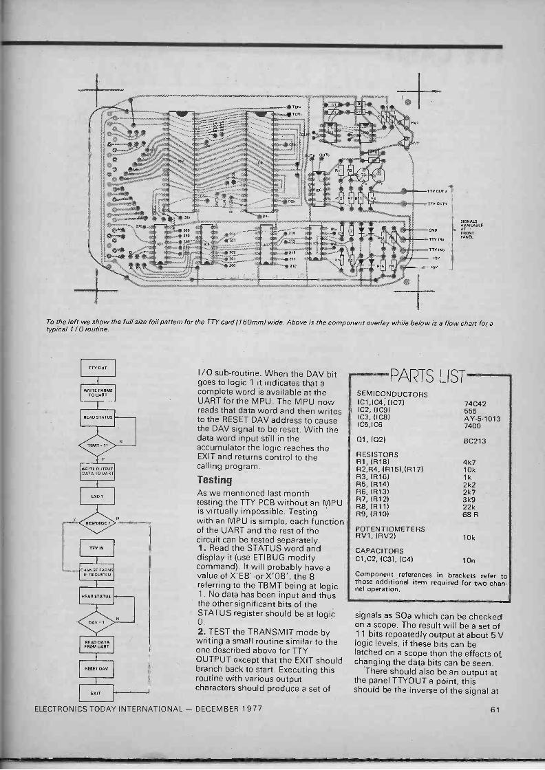
SIGNALS AVAILABLE - AT FRONT PANEL
To the left we show the full size foil pattern for the TTY card (160mm) wide. Above is the component overlay while below is a flow chart for, a typical 1 / 0 routine.
ITT OUT
}
WRITE PARMS TO UART
}
READ STATUS
WRITE OUTPUT DATA TO UART
}
END 7
ITT IN
}
CHANGE FARMS IF REQUIRED
READ STATUS
READ DATA FROM UART
}
RESET DAV
}
EXIT
I /O sub -routine. When the DAV bit goes to logic 1 it indicates that a complete word is available at the UART for the MPU. The MPU now reads that data word and then writes to the RESET DAV address to cause the DAV signal to be reset. With the data word input still in the accumulator the logic reaches the EXIT and returns control to the calling program.
Testing As we mentioned last month testing the TTY PCB without an MPU is virtually impossible. Testing with an MPU is simple, each function of the UART and the rest of the circuit can be tested separately. 1. Read the STATUS word and display it (use ETIBUG modify command). It will probably have a value of X'E8' or X'08', the 8 referring to the TBMT being at logic 1. No data has been input and thus the other significant bits of the STATUS register should be at logic O.
2. TEST the TRANSMIT mode by writing a small routine similar to the one described above for TTY OUTPUT except that the EXIT should branch back to start. Executing this routine with various output characters should produce a set of
ELECTRONICS TODAY INTERNATIONAL - DECEMBER 1977
PARTS LIST SEMICONDUCTORS IC1,IC4, (IC7) IC2, (1C9) IC3, (IC8) IC5,IC6
Q1, (02)
RESISTORS R1, (R18) R2,R4, (R15),(R17) R3, (R16) R5, (R14) R6, (R13) R7, (R12) R8, (R11) R9, (R10)
74C42 555 AY -5-1013 7400
BC213
4k7 10k 1k 2k2 2k7 3k9 22k 68 R
POTENTIOMETERS RV1, (RV2) 10k
CAPACITORS C1,C2, (C3), (C4) 10n
Component references in brackets refer to those additional item required for two chan- nel operation.
signals as SOa which can be checked on a scope. The result will be a set of 1 1 bits repeatedly output at about 5 V logic levels, if these bits can be latched on a scope then the effects of changing the data bits can be seen.
There should also be an output at the panel TTYOUT a point, this should be the inverse of the signal at
61

T TY ChilD SOa and should also swing through about 12 V logic level changes. 3. With the transmit mode tested it should be simple to see the changes in the parameter bits reflected on the data stream displayed on the scope. 4. Connect the points TTYOUTa and TTYINa at the front panel and repeat the test for the transmit mode. Now the data at point Sla can be checked, it should be identical to that at point SOa escept that the logic swing will be TTL not 12 V. 5. To test the input mode of the UART it is necessary to write a
subroutine similar to the one shown above and execute it in OUTPUT plus RESPONSE mode. With TTYOUTa tied to TTYINa the data word input should be the same as that output with no errors in parity, framing or over -run. One point to note is that it is possible for the DAV line to be set before the first read operation after power -on or similar conditions. This would result in he over -run indicator being set for a valid word. Also note that you must remember the logic of the UART allows one word to sit in the transmit register, one in the transmit buffer, one in the receive buffer and a possible fourth in the receive register. Normally this is an advantage but in some ciscumtances it could make life very complex.
Cassette Interfaces Discussion of any cassette interface can be broken down into three topics - the Digital/Analogue/Digital interface to the recorder, the mode of recording and the MPU I/O software. This month we show you a very simple cassette interface using a UART with a flowchart of a very simple I /O routine.
The circuit of the recorder interface shows how it is connected directly to the SI, SO, RCP and TCP of the UART. With a 4 800 Hz signal connected to the TCP and RCP pins of the Uart any transmitted data will appear at the SO output and thus gate the 4 800 Hz through the 7402 gate on and off. This output is then attenuated and coupled through R3 and C4 to the recorders AUX input.
In the playback mode the signal from the recorder is interfaced to TTL level and filtered by the network shown and then input to the UART SI input.
This system is suitable when the same recorder is to be used for both input and output as variations in motor speed could adversely affect
UART
TCP
RC P
SO
SI
4800H
R3 C4 -- 4-1 I 7402
10n
Circuit of a simple cassette interface.
operation. The mode of recording is
obviously to encode a 4 800 Hz tone or nothing on the tape for each logic 1 or 0 output, it may be possible to use a stereo recorder to output a
continuous 4 800 Hz tone on one track, this could then be recovered and used as an RCP signal for the UART thus overcoming the motor speed problem.
Getting Better The third part of a cassette interface can be the most complex if all error conditions are noted and attempts made to correct data. It is possible to connect the recorder, turn it on to record and simple output data as and when necessary. An example of this is if the cassette is copying data output to a printer or other remote device, the resulting tape may contain long pauses at random places, perfectly acceptable but difficult to read back in again.
The more conventional cassette routines transmit a block of data complete with header and or trailer data to indicate block length, starting location, block parity checks,and possibly date and title information.
Let us consider a cassette routine which will output a 256 byte block of data plus the originating location and a simple checksum. First the routine must output two bytes to indicate the original location of the 256 block, this can then be used or not as required by the input routine. Two counters are then cleared by the routine, the first is used to count the number of bytes and the second is used to generate a block parity checksum.
Each of the 256 bytes is now output in a sub -loop which adds 1 to count 1 and adds the data to count 2. When 256 bytes have been output the routine outputs count 2
AUX
thus causing a total of 259 bytes to be output to the recorder.
The input routine waits for data from the recorder knowing that the first two bytes to arrive will be the originating address of the data, if the data is to be input to its original area these bytes can be loaded into an index register so that the following data can be stored offset to that register. Counts 1 and 2 are now cleared and the main data awaited, again each data byte input is added to count 2 and 1 is added to count 1
When count 1 equals 256 the last data byte is read from the tape and compared to count 2, if they are the same then the read is probably successful.
Error checking of each byte can be ignored as any error is likely to disrupt the whole block and thus be noticed in the block check. The check on each block of data consists of two checks, firstly that 256 data bytes have been input if not then a framing or overrun error may have occurred. The second check is the comparison of the calculated count 2 with that stored on the tape, as both counts were obtained by using the same method then in a perfect block both should be the same. Neither check is foolproof but a combination should trap all bad reads.
Cassette Recorders Treat your data as you would an expensive LP or cassette and you should avoid most problems. Keep the cassettes in cases with a filing system - dust is a destroyer. Don't use El Cheapo brand recorders or cassettes and expect perfection - treat yourself to a good machine and a stock of new tapes. Don't do anything to the recorder whilst it is reading or writing a block of data, wait for an inter -record gap (20 second or so). ETI
62 ELECTRONICS TODAY INTERNATIONAL - DECEMBER 1977

BATTERIES may be divided into two general classes; primary batteries and secondary batteries. Primary batteries or cells (strictly speaking, a battery is a group of cells connected together, but the term battery is commonly used for either form), only has a single working life. In general, once discharged, their capacity to provide useful power ceases and they must be discarded. A primary cell can provide power as soon as it is assembled and requires no initial charging current.
Five types of primary cell are currently available. These are:- Leclanche (or carbon -zinc) cell Mercury cell Alkaline cell Zinc -Air cell Weston Cadmium cell Secondary batteries or cells require -an
initial charging current before they can be used, in the opposite polarity (or direction) to their discharge current. They can go through many charge -discharge cycles throughout their useful life, and can be stored for considerable periods in a discharged condition without deteriorating. Secon- dary batteries are also referred to as storage batteries. Two types of second- ary battery are in common use:- Lead-Acid battery Nickel -Cadmium battery (familiarly called the Nicad).
THE LECLANCHE CELL The construction and composition of a
cylindrical Leclanche cell is as follows. The cell's outer casing is formed from zinc and this acts as the negative elec- -trode. A central carbon rod, which is
1.6
1.4-
1.2-
1.0-
ORDINARY DRY CELL
0.8
PART 14 OF OUR COMPONENT SERIES LOOKS AT, PERHAPS, THE LEAST UNDERSTOOD AND MOST ABUSED OF
ELECTRONIC COMPONENTS.
connected to an external metal cap, forms the positive electrode. The carbon rod is surrounded by a
mixture of manganese dioxide and powdered carbon in a porous sack. This is called the 'depolariser'. The rest of the cell is filled with a paste of ammonium chloride - the 'electrolyte'. The Leclanche or carbon -zinc cell, is commonly known as a dry cell.
These cells, have a no-load terminal voltage of 1.5 to 1.6 volts. The energy that they can supply is related to their size. Under -load the terminal voltage of dry cells gradually decreases and internal resistance rises. When the load is removed terminal voltage rises again, but not to the original value. Over a number of discharge -rest periods, the no-load terminal voltage will gradually decrease as will the amp -hour capacity of the cell (Fig. 1.)
Once the no-load voltage drops to 1
volt or so the cell has come to the end of its useful life and should be given a
decent burial. Leclanche cells are best suited to applications that require intermittent use or low -drain use for long periods.
Heavy duty -dry cells are available that will provide much higher discharge currents. These will supply several hundred milliamps for four to five hours at a time, whereas the ordinary cell will typically provide 100 mA or less for similar periods. As might be expected, they cost more than ordinary dry cells.
The heavy duty dry cell deteriorates more slowly than conventional cells and will undergo more discharge -rest cycles before requiring replacement. They are sometimes marketed as 'Longer -Life' batteries. Conventional and heavy duty dry cells are compared in Fig. 1.
HEAVY DUTY DRY CELL
Fg. 1. Performance of ordinary and heavy duty dry cells discharged for several hours per day at fairly heavy current.
ELECTRONICS TODAY INTERNATIONAL - DECEMBER 1977
TIME
Size is not the only factor which governs the life of a dry cell. The ratio of the period of use to the rest period is an important factor. The old door -bell batteries which were about the size of a drink can would last for years. They could supply up to one amp but their rest -to -use ratio was very high. Temperature also affects the
performance of dry cells. Optimum is between 20°C and 27°C. Terminal voltage and capacity is drastically reduced below 15°C, and almost useless below 5°C. Leclanche cells deteriorate when stored for long periods. Generally, the larger the cell, the less the de- -terioration.
Leclanche cells have a serious drawback. When left for long periods in a discharged conditon the outer zinc container is gradually eaten away by the electrolyte which then finds its way to the outside, corn:; i 1g surrounding equipment. Leak versions are available, but these should not be left too long discharged either.
The internal resistance of a Leclanche cell rises steeply as it discharges. This can give rise to low frequency instability ('motorboating') in amplifiers. A large value electrolytic (1000 µ +) across the supply rail will often eliminate this problem, and will often dramatically improve the sound reproduction from a transistor radio.
Fresistaritcations requiring six volts or more at low currents, the layer battery has been developed. These are made up of square or rectangular layer cells, their shape enabling them to be grouped together with minimum waste of space. The common 9 V transistor radio battery is of this type. They suffer less deterioration than the round style dry cell. They are relatively low current devices. Round cells are better where fairly heavy consumption for fair periods is required.
THE MERCURY CELL The mercury cell was invented in
World War II by Dr Samual Ruben. It has an anode of high purity amalgamated zinc and a cathode of compressed mercuric oxide -graphite separated from the anode by an ion -permeable barrier. The cathode is in contact with a steel container which provides the terminal connection. The
65
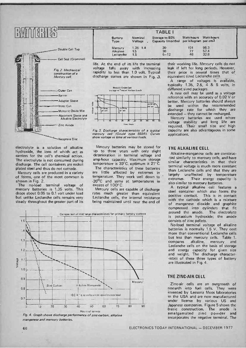
D
D
TABLE I
Battery Nominal Storage to 80% Watt-hours Watt-hours Type Voltage Capacity (months) per kilogram per cm3
Double Cell Top Mercury Alkaline
1.35-1.4 1.5
30 30
101 77
98.3 57.4
Leclanche 1.5 6-12 48 32.8
Cell Seal (Grommet)
Fig. 2. Mechanical construction of a Mercury cell.
Outer Can
Barrier
Adapter Sleeve
Inner Can
Mercuric Oxide Mix
Absorbent Sleeve and Alkaline Electrolyte
Zinc Anode
Neoprene Disc
electrolyte is a solution of alkaline hydroxide, the ions of which act as carriers for the cell's chemical action. The electrolyte is not consumed during discharge. The cell containers are nickel plated steel and thus do not corrode. Mercury cells are produced in a variety
of forms, one of the most common is
shown in Fig. 2. The no-load terminal voltage of
mercury batteries is 1.35 volts. This drops about 0.05 to 0.1 volt under load but unlike Leclanche cells remains very steady throughout the greater part of its
1.5
1.4
1.3
1.2
á 1.1
1.0
0.9
0.8
0.7
life. At the end of its life the terminal voltage falls away with increasing rapidity to less than 1.0 volt. Typical discharge curves are shown in Fig. 3.
Mecuric Oxide Cell Voltage vs Time at Various Loads
4
` 1.2
25 Ohms
Per cell 1.0 50 ms
per cell
10 hms per cell
0.8
05 0 5 10 15 20 25 30 35 40 45 5(
T. me, Hours
Fig. 3. Discharge characteristics of a typical mercury cell (Gould type 502R). Curves show voltage vs time at various loads.
Mercury batteries may be stored for up to three years with only slight deterioration in terminal voltage and amp -hour capacity. Maximum storage temperature is 30°C, optimum is 21° C.
The characteristics of these batteries are little affected by extremes in temperature. They work well down to -20°C and some at temperatures in excess of 100° C.
Mercury cells are capable of discharge rates much greater than equivalent Leclanche cells, the internal resistance being maintained until near the end of
Comparison o discharge characteristics for primary battery systems
`, . W
N.
`. Zinc Carbon At IICII mu Manganese s.,` Mercury
IEC R1 size cells under co 11inuous load
10 20 30 40 50 GO
Hours of service Fig. 4. Graph shows discharge performance of zinc -carbon, alkaline manganese and mercury batteries.
70 80 90
their working life. Mercury cells do not leak if left for long periods. However, their price is several times that of equivalent sized Leclanche cells.
A range of voltages is available, typically 1.35, 2.5, 4 & 8 volts, in different sized packages.
A new cell may be used as a voltage reference with an accuracy of 0.02 V or better. Mercury batteries should always be used within the recommended discharge rate for which they are intended - they cannot be recharged.
Mercury batteries are used where voltage stability and long life are required. Their small size and high capacity are also advantageous in some applications.
THE ALKALINE CELL Alkaline -manganese cells are construc-
-ted similarly to mercury cells, and have similar characteristics in that their terminal voltage is much more constant than Leclanche cells and that they are largely unaffected by temperature extremes. Their energy capacity is
also similar to mercury batteries. A typical alkaline cell features a
steel container which also forms the positive contact. This is in contact with the cathode which is a mixture of manganese dioxide and graphite compressed into cylinders that fit around the anode. The electrolyte is potassium hydroxide; the anode consists of zinc pellets.
No-load terminal voltage of alkaline batteries is normally 1.5 V. They cost more than conventional Leclanche cells but less than mercury cells. Table 1. compares alkaline, mercury and Leclanche cells on the basis of storage and energy capacity for given size and weight. The discharge character- -istics of these three types of battery are illustrated in Fig. 4.
THE ZINC -AIR CELL
Zinc -air cells are an outgrowth of research into fuel cells. They were invented by Leesona Moos laboratories in the USA and are now manufactured under license by various US and Japanese companies. Figure 5 shows the basic construction. The anode is amalgamated zinc powder and incorporates the negative terminal. The
66 ELECTRONICS TODAY INTERNATIONAL - DECEMBER 1977

electrolyte, a concentrated solution of potassium hydroxide, is in contact with the anode. This construction allows large discharge currents without serious polarisation of the anode occurring. The anode structure is held in a tough plastic case.
The cathode is constructed in several layers, held in a plastic frame. The outermost layer is a micro -porous PTFE plastic film. This allows atmospheric oxygen to come in contact with the electrolyte. The PTFE will allow air into the cell but will prevent the electrolyte escaping. Thus, the battery may be used in any position. On the inner face of the PTFE is a layer of catalyst. This is also
CATHODE -7
PLASTIC CASE
ZINC -AIR CELL
Fig. 5. Section of rectangular zinc -air cell.
in contact with the electrolyte and aids the chemical action of the cell without itself being consumed. The catalyst used provides a high current density at the cathode.
A metal mesh collects the current generated by the cell and is the positive terminal connection. A permeable separator allows free passage of ions within the cell but prevents direct electrical contact between anode and cathode.
Zinc air cells find most use in
32
2.8
2.4
2-0
> 16
1.2
0.8
applications requiring continuous or semi -continuous service at high currents. They have high energy to weight and volume ratios and have higher current output and amp -hour capacities than equivalent size alkaline or mercury cells.
The maximum current capability of zinc -air primary cells is dependant on cathode area. Their amp -hour capacity is dependant on the volume of the zinc anode. The cathode will operate continuously provided its surface has sufficient access to the air.
Depending on the application, a
zinc -air cell may produce six to eight times the output of an equivalent high power Leclanche cell or a weight saving of the same order for equivalent power outputs. (Leclanche cells are not of course capable of the high discharge rates of the zinc -air cells).
Zinc -air cells can deliver high currents continuously at a voltage which remains nearly constant throughout the discharge system. A comparison of the -
discharge characteristics of various cells and zinc -air batteries of equivalent size is given in Fig. 6. Zinc -air cells have a nominal terminal
voltage of 1.4 V on no-load dropping to 1.2V -1.1V under load with an end point voltage of 0.9 volts (discharged). Very small cells (AA size) can provide continuous discharge currents of 250 mA and up to 500 mA peak. This size cell would typically have a capacity of 2.5 amp -hours after three months storage. Leclanche cells of equivalent size have a capacity measured in milliamp-hours. Zinc -air cells can provide 185 watt-hours per kilogram -
, compare this with the other primary cells in Table 1. Their main drawbacks are cost and
availability.
THE WESTON CADMIUM CELL This cell is used only as a primary
voltage standard or reference. It is
unable to supply useful current - in fact a discharge current greater than about one milliamp will ruin it. The
Zinc Air
10 11
HOURS Fig. 6. Discharge curves of various types of cell compared -to a zinc -air battery of the same physical size.
terminal voltage of a Weston Cadmium cell is 1.01864 volts at 20°C. It's not what you 'would call a handy figure to work with (especially using it in calculations!), its advantage lies in the fact that it can be quoted within plus or minus ten microvolts.
The cathode (+ve) of the weston cell is mercury and mercurous sulphate paste. The anode (-ve) is an amalgam of cadmium and mercury in saturated cadmium sulphate.
The cell is usually contained in an H-shaped glass vessel as illustrated in. Fig. 7. To maintain the accuracy of the output voltage, the cell is often constructed in a temperature regulated container.
GLASS VESSEL
SATURATED CADMIUM
PASTE
CADMIUM SULPHATE CRYSTALS
MERCUROUS SULPHATE PASTE
Velr MERCURY
CADMIUM + AMALGUM
POSITIVE TERMINAL
NEGATIVE TERMINAL
Fig. 7. The Weston Cadmium cell.
THE LEAD -ACID BATTERY We shall now deal with the two most
common types of secondary cell. The lead -acid battery has a long and
honourable history. The car battery is probably the most familiar example. High current capabilities, long life and relatively low cost are attractive advantages. A forty amp -hour capacity car battery can supply several hundred amps for periods of a few seconds (i.e.: for a car starter motor).
The lead -acid cell consists of a lead and litharge (lead oxide) anode and a lead and red -lead cathode immersed in a liquid electrolyte of dilute sulphuric acid. This is contained in a hard rubber or polypropylene case. A filler cap for the electrolyte is provided and a vent hole for the release of gas during charging. For this reason, conventional lead -acid batteries can only be used in the upright position.
Lead -acid batteries are obtainable in a wide variety of sizes and amp -hour capacities. Some are designed for heavy duty service while others are designed for light or intermittent duty.
ELECTRONICS TODAY INTERNATIONAL - DECEMBER 1977 67

117UNGIA
They are of course produced for innumerable applications other than the starting, lighting and automobile ignition applications.
The fully -charged, no-load terminal voltage of a lead -acid cell is between 2.3 - 2.4 volts. This drops under load to about 2.0 - 2.2 volts. When discharged, the cell voltage is typically 1.85 volts. The amp -hour capacity is determined from a 10 hour discharge rate. The current required to discharge the battery to its end -point voltage of 1.85 V/cell is multiplied by this time. e.g: a 40 AH battery will provide 4 amps for 10 hours before requiring recharge. Note however that the amp -hour capacity varies with the discharge current. The same battery discharged at a rate of 10 amps will not last four hours, on the other hand if it is discharged at 1 amp it will last somewhat longer than 40 hours. The discharge characteristics are shown in Fig. 8.
Lead acid batteries may be operated over a wide range of temperatures, from -20°C to +35°C. At low temperature, amp -hour capacity and discharge current are reduced and there is the possibility of the electrolyte freezing, depending on the specific gravity of the electrolyte. Preferred operating temperature is about +20°C to +25°C.
A direct indication of the state of charge in a lead -acid battery is the specific gravity of the electrolyte. This is measured with a hydrometer. These can be obtained calibrated specifically for use with lead -acid batteries. The hydrometer reading for full charge will lie somewhere between 1.210 and 1.275, depending on the type of service for which the battery was intended. Table 2 shows the values of specific
gravity expected in the various types of Lead -Acid batteries.
TABLE 2 S.G. USE 1.210 emergency lighting, low duty. 1.245 light and intermittent duty. 1.260 car batteries. 1.275 heavy discharge, truck and tractor
batteries.
Charging is a fairly simple operation. The unfiltered output of a rectifier (dirty dc) may be used or any power supply that will provide the appropriate current at a voltage a little above the battery's fully charged terminal voltage. Some means of varying the charging current is necessary. High wattage, low
1.0
0
Fig. 10. Discharge characteristics of Lead -Acid cells.
10 HOUR DISCHARGE RATE
voltage lamps in series with the battery áre suitable for the raw dc type of charger.
The initial charging current for the fully discharged battery (cell voltage under 2.0 V), should be about 20 amps per 100 amp -hours of capacity (i.e.: 8 amps for a 40 AH battery). Once the electrolyte begins to gas rapidly, the cell voltage will be around 2.3 volts and rising rapidly. At this point, the charging current should be reduced to somewhere between 4-8 amps per 100 AH until charging is complete. Check the specific gravity at half-hourly intervals. At the end of charging, cell voltage may rise to about 2.6 volts or more but this decreases slowly after the charger is removed, the terminal voltage then usually reading around 2.4 volts -per cell (Fig. 9).
Slower charging rates can be used, the battery taking longer to recharge. A continuous low -rate charge can be used ('trickle charging'). A constant current charger is best in this application, providing between 100 mA and 300 mA per 100 AH capacity.
During charging, the electrolyte temperature should not be allowed to rise above 38°C (100°F). If the battery is hot and gassing rapidly, reduce the charging current.
Hydrogen is released during charging. This is highly explosive. Keep flames and cigarettes away and avoid electrical
2.6 -
w 2.4 - 1--
(7,1 2.3- > J z 2.2-
F 2.1-
2.0
10 TIME (HOURS)
sparks by turning off the charger when connecting or disconnecting leads to the battery terminals.
Lead -acid batteries should be charged in an open area where small electrolyte spillages and fumes cannot affect nearby materials. Cotton and synthetic materials are attacked by sulphuric acid and mysterious holes appear where the material has come into contact with battery electrolyte.
The level of the electrolyte in each cell of a battery must be kept above the top of the plate. The loss of water by evaporation and decomposition during charging should be made up with distilled water. Do not use tap water as it usually contains minerals and traces of chemicals that contaminate the electrolyte. Distilled water is best added when the cells are gassing to ensure thorough mixing.
If a lead -acid battery is used at relatively light duty then it should be periodically discharged through a dummy load, at its normal rate, and then immediately recharged.
Lead -acid batteries should not be overcharged at high current as this causes the plates to buckle and slake (which may result in a short circuit). Neither should they be left in a discharged state as the lead sulphide produced during discharge may undergo a generally irreversible physical change resulting in reduced battery capacity.
CHARGING RATE REDUCED
RAPID GASSING OCCURS
0 2 4 1
Fig. 9. Charging characteristics of Lead -Acid cells.
I I I I 1
6 8 10 TIME (HOURS)
68 ELECTRONICS TODAY INTERNATIONAL - DECEMBER 1977

Batteries in this condition are referred to as 'sulphated'. This condition may sometimes be remedied, at least partially, by trickle charging for a
considerable period. Eventually, sulphated cells self -discharge.
In normal operation, lead -acid batteries should be overcharged from time to time, at about half the normal rate, until half-hourly readings of the terminal voltage and electrolyte specific gravity show no further increase. This action removes sulphate and restores the plates to their normal condition. Spilled electrolyte should be
neutralized with an alkaline solution. This is simply made up by dissolving 4-6 tablespoons of common baking soda (sodium bicarbonate) per litre of water, using as much water as necessary. When applied to spilled electrolyte, foaming occurs. When the foaming has stopped the residue should be washed away with clean water. If washing down the top of a battery with this solution, do not let any into the cells!
THE NICKEL -CADMIUM CELL (Nicad)
Nicad cells use a potassium hydroxide electrolyte. In a typical unit the positive and negative plates are both perforated
steel. The positive plate is filled with nickel hydroxide, the negative plate with finely divided cadmium mixed with a little iron to prevent it flaking and losing porosity. The electrolyte has a specific gravity of 1.15-1.2, depending on the type of service, it does not undergo any chemical change during discharge. Very little electrolyte is needed and the positive and negative plates are very closely spaced.
Nicad batteries are made in a wide variety of sizes and amp -hour capacities, miniature ones for use in cameras, calculators etc up to large heavy duty types similar to car batteries. They may be operated over a wide temperature range - similar to that of lead -acid
2.2-
2.1-
2.0
1.9-
1.8 0
Gaps? It can be a nuisance can't it, going from newsagent to newsagent? "Sorry squire, don't have it - next one should be out soon."
Although ETI is monthly, it's very rare to find it available after the first week. If it is available, the newsagent's going to be sure to cut his order for the next issue - but we're glad to say it doesn't happen very often.
Do yourself, your newsagent and us a favour. Place a regular order for ETI; your newsagent will almost certainly be delighted. If not, you can take out a postal subscription so' there's nothing for you to remember - we'll do it for you.
For a subscription, send us £6.00 (£7.00 overseas) and tell us which issue you want to start with. Please make your payment (in sterling please for overseas readers) to ETI Subscriptions and keep it separate from any other services you want at the same time.
ETI Subscription Service Electronics Today International
25-27 Oxford Street, London, W1 R 1 RF
ELECTRONICS TODAY INTERNATIONAL - DECEMBER 1 977
2
batteries. At low temperatures, the amp -hour capacity does not diminish as much as with lead -acid batteries. However, the electrolyte may freeze.
As Nicad batteries may be sealed, they can be used in any position. The no-load terminal voltage of a nickel -cadmium cell is typically 1.3-1.4 volts. This drops to about 1.2 volts under load, and to about 1.1 volts when discharged. As the electrolyte does not change during discharge (as it does in lead -acid batteries), the number of amp -hours obtained from a Nicad battery is much less affected by the discharge rate than are lead -acid batteries (Fig. 10).
As Nicad batteries can be made quite small, and can be recharged, they are
Fig. 10. Discharge characteristics of Nickel -Cadmium cells.
10 HOUR DISCHARGE RATE
3 HOUR DISCHARGE RATE
1 1 1 1 1 1 I
4 6 8 10
TIME (HOURS)
BARGAIN PARCELS SAVE POUNDS Huge quantities of electronic components must be cleared as space required. 1000's of capacitors, resistors, transistors. Ex -equipment panels, etc. covered in valuable' components. No time to sort. Must sell by weight 7Ibs-£4.95, 141bs-£7.95, 281bs-£12.00, 561bs-£20.00, 1 121bs-£30.00
BARGAIN PACKS Handy Packs
4 aluminium boxes 128 x 44 x 38mm, ideal for signal injectors, etc. £1.00 Self -fluxing enamelled copper wire 18 and 22 swg on 2oz. reels . 2 for £1.10 100 miniature reed switches, ideal for burglar alarms, model railways, etc.
£2.20 15 2 -pole reed relays on board operate at 12 volts £2.45 6 6 -pole 12 volt reed relays on board
£2.45 High quality computer panels smothered in top -grade components:
5lbs. £4.75 t 01bs. £8.95
New U.H.F. transistor TV tuners, 4 push-button type £2.50 Rotary type with slow motion drive £2.50 Aluminium TV coax plugs 10 for £1.00 20mm anti -surge fuses, your selection 500mA to 3.15A 12 for £1.00 Hardware Packs, each includes 84 nuts
and bolts, nylon, self -tapping, Posi -
drive, "P" -clips, cable clamps, fuse holders, etc., etc. 100s of items in every pack £1 per lb.
25 mixed pots and prents £1 100 mixed electrolytics £2.20 100 mixed wire wound resistors
. £1 300 printed circuit resistors £1
Component Bargains 300 mixed resistors % & Ya watt £1.00 200 modern mixed caps most types
£3.30 100 mixed polyester caps . £1.40 100 mixed modern miniature ceramic
plate caps most values to 1000 PF .
£2.20 100 mixed polystyrene caps to 5000 PF
£2.20
Semiconductor Bargains 100 new and marked silicon and
germanium transistors including BC148, BF194, BC183, etc. £3.95
200 new and marked transistors including 2N3055, AC128, BFY50, BD131, etc.
£6.95 100 mixed diodes IN4148, etc. £1.20 100 mixed diodes including zener, power
and bridge types £3.30 200 unmarked mixed transistors, lots of
interesting types including power. Send 60p for samples £4.50
25 new and marked integrated circuits including 555, 741, 7400, 7490, TBA 800, CD4001, etc. £4.70
BR 101 fulbspec. 5for £1.00 DY 51 EHT Rectifier £1.00 TBA 120A 2-C1
DELUXE FIBRE GLASS PRINTED CIRCUIT ETCHING KITS Includes 150 sq. ins. copper clad f/g board, 11b. ferric chloride, 1 dab etch resist pen, abrasive cleaner, 2.mini drill bits, etch tray and instructions - only £5.30.
REFILL PACKS FOR ABOVE 150 sq. ins. fibre glass board Dalo pen 1Ib ferric chloride to mil spec. 5lbs ferric chloride to mil spec. Instruction sheet
£1.50 90p
£1.00 £4.00
20p 30p P. & P. ON ALL ABOVE ITEMS. SEND CHEQUE OR POSTAL ORDER WITH ORDER TO SENTINEL SUPPLY, DEPT. ETI 20A WADDON ROAD, CROYDON, SURREY
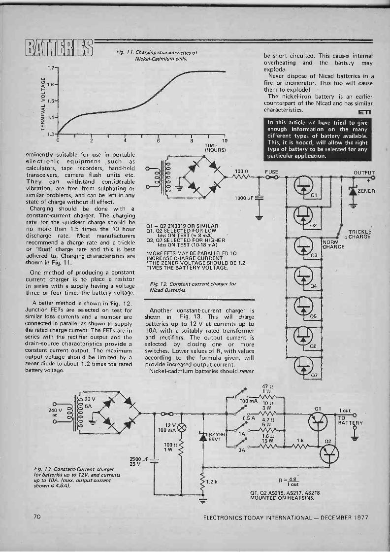
IHEULM
W
1.7
1.3
o
Fig. 11. Charging characteristics of Nickel -Cadmium cells.
eminently suitable for use in portable electronic equipment such as calculators, tape recorders, hand-held transceivers, camera flash units etc. They can withstand considerable vibration, are free from sulphating or similar problems, and can be left in any state of charge without ill effect.
Charging should be done with a
constant -current charger. The charging rate for the quickest charge should be no more than 1.5 times the 10 hour discharge rate. Most manufacturers recommend a charge rate and a trickle or 'float' charge rate and this is best adhered to. Charging characteristics are shown in Fig. 11.
One method of producing a constant current charger is to place a resistor in series with a supply having a voltage three or four times the battery voltage.
A better method is shown in Fig. 12. Junction FETs are selected on test for similar Idss currents and a number are connected in parallel as shown to supply the rated charge current. The FETs are in series with the rectifier output and the drain -source characteristics provide a
constant current output. The maximum output voltage should be limited by a
zener diode to about 1.2 times the rated battery voltage.
oc) 20V 5A
240 V ac
Fe. 13. Constant -Current charger for batteries up to 12V. and currents up to 10A. (max. output current shown is 4.6A).
10 TIME (HOURS)
100 S2
1000 p F
01 - 07 2N3819 OR SIMILAR Q1, 02 SELECTED FOR LOW
Idss ON TEST 8 mA) 03, 07 SELECTED FOR HIGHER
Idss ON TEST (10-18 mA)
"MORE FETS MAY BE PARALLELED TO INCREASE CHARGE CURRENT *THE ZENER VOLTAGE SHOULD BE 1.2 TIMES THE BATTERY VOLTAGE.
Fig. 12. Constant -current charger for Nicad Batteries.
Another constant -current charger is shown in Fig. 13. This will charge batteries up to 12 V at currents up to 10A with a suitably rated transformer and rectifiers. The output current is
selected by closing one or more switches. Lower values of R, with values according to the formula given, will provide increased output current.
Nickel -cadmium batteries should never
2500 p F 25 V
be short circuited. This causes internal overheating and the battery may explode.
Never dispose of Nicad batteries in a
fire or incinerator. This too will cause them to explode!
The nickel -iron battery is an earlier counterpart of the Nicad and has similar characteristics. ET1
In this article we have tried to give enough information on the many different types of battery available. This, it is hoped, will allow the right type of battery to be selected for any particular application.
FUSE
47 S
1W
100 mAc_ 102 /o_/W V'
0.5 A 4.7 S2
12 V 100 mA cf
BZY96 1A
100 2 1W
65V 1 1.6 S2
15W
3A °-Mn
1.2 k
Q2
Q3
Q1
R _ 4.8 I out
01, Q2 AS215, AS217, AS2T8 MOUNTED ON HEATSINK
OUTPUT
ZENER
-977
TRICKLE o CHARGE
NORM CHARGE
I out
TO BATTERY
I
70 ELECTRONICS TODAY INTERNATIONAL - DECEMBER 1977

A GATE CIRCUIT, in general, is a circuit which will allow a signal to pass for a time defined by another signal, often a rectangular pulse (Figure 1 a). In linear circuitry we need linear gates which do not affect the shape of the signal which is gated, but in digital circuitry all the signals are steady voltage levels, 1 or 0, or fast transistions between these levels, so that speed of operation is important and no linear action is needed. Ideally, a perfect switch is also a perfect digital gate.
Logic gates are of two basic types, the AND the OR type. The simplest examples of each have two inputs and one output, though up to 13 inputs are found in some types. Taking the two input AND gate, the output is a logic 1 when, and only when, both inputs are also at logic 1 (A and B are at 1); the output is zero for any other combination of inputs. The two input OR gate gives a logic 1 output when either input is a logic 1, or when both are at logic 1 (A or B or both).
NvtnVWVI
(a)
A ¡ ) Q A
B Il B
AND (b)
Q
Fig. 1. Gates. (a) General gating action . (b) Logic gate symbols.
AND-GATE
P B 1 1
1 o
0 1
o o
n 1
o
o
o
(a)
OR-GATE
A 1
1
o
o
B
o 1
o
O
1
1
1
o
Fig. 2. Truth tables. (a) AND -gate. (b) OR -gate.
(b)
These actions can be summarised in a truth table which shows at a glance what combinations of inputs and outputs are possible. Fig 2 shows the truth tables for the AND and OR gates. Truth tables, though useful, become rather bulky when the gate has a large number of inputs, so that a better way of memorising the action is to remember that only when all inputs are 1 is the output of the AND gate 1, and only when all inputs are zero is the output of the OR gate zero.
NAND and NOR gates have outputs which are the inverse of the AND or OR gates respectively, as the truth tables of Fig.3 show; internally these gates are AND/OR gates with inverters at the outputs. Another gate encountered at times is the exclusive -OR (XOR) which has the truth table and symbol shown in Figs. 3c, d. Note that the action is that of the OR gate, except that the output is 0 when both inputs are 1.
Working over a 7400
The second IC we shall deal with in this series is a 7400 quad NAND gate. This consists of four separate two -input NAND gates, and like all the other ICs used in this series is a TTL circuit. An unconnected input will therefore float to logic 1, and will need a current of 1.6 mA to be sunk to hold it down to logic 0.
Start work on this gate by connecting the power supply leads. Pin 7 is taken to the negative line by a wire connection, and pin 14 is similarly taken to the +5 V line. The connections to the gates are shown in Fig.4; we shall start by using gate 1.
Connect a 47OR resistor between pin 3 and a spare pad, as shown in Fig. 5. Now connect another LED between the spare pad and the zero line to act as an indicator to light when the output is at logic 1- we could obtain inputs by soldering in wires, but this is rather tedious.
Wire up the switches as shown in Fig. 5, wiring the terminals directly to the "0" line and the spare pads. Since these are press -to -make switches, their effect will be to give a logic 0 when pressed, the input to which they are connected will then float to logic 1 when the switch is released.
Miniature slide switches were tried, but found to short 1 to 0. With the switches in place, check the truth table for a NAND gate, using the LED to indicate the state of the output. The truth table should agree with that of Fig. 2a.
Now investigate the effect of adding an inverter, by joining a wire from pin 3 of the 7400 to pin 1 of the 7414, using the LED which is connected to pin 2 of the 7414 as the output indicator (Fig. 6). This connection,
76 ELECTRONICS TODAY INTERNATIONAL - DECEMBER 1977
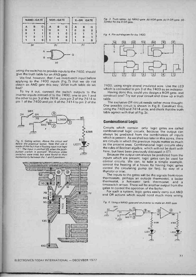
NAND-GATE
A 0 0
1
1
B
0
1
0
1
Q
1
1
1
o
NOR-GATE
A B Q 0 0 1
0 1 0 1 0 0 1 1 0
X-OR GATE
A B Q
0 0 0 0 1 1
1 0 1
1 1 0
(a) (b) (c)
B1D-Q (d)
using the switches to provide inputs to the 7400, should give the truth table for an AND gate.
We find, however, that if we invert each input before applying to the 7400 inputs (Fig.7) that we do not obtain an AND gate this way. What truth table do we find?
To try it out, connect the switch outputs to the inverter inputs instead of to the 7400, one to pin 1 and the other to pin 3 of the 7414. Join pin 2 of the 7414 to pin 1 of the 7400 and pin 4 of the 7414 to pin 2 of the
Fig. 5. Gating action. Above the circuit and below the practical layout. Note that use is made of the fact that a floating input is at logic "1". The input is earthed (0) when the push- button switch is pressed. Miniature slider switches were tried, but were found to short momentarily between the 1 and 0 positions.
:............. ........................ ......................
7G
8G
9G
13G
CD C n
18G' >:: ï :;::. . .......
9G
::::: _:::::;:::::::
7
Fig. 3. Truth tables. (a) NAND -gate. (b) NOR -gate. (c) X -OR -gate. (d) Symbol for the X -OR -gate.
Fig. 4. Pin -out diagram for the 7400.
7400, using single strand insulated wire. Use the LED which is connected to pin 3 of the 7400 as an indicator.
Having done this, could you design a NOR gate, and construct one? Try out your circuit and draw up a truth table.
The exclusive -OR circuit needs rather more thought. One possible circuit is shown in Fig.8. Construct this, using the 7400 and 7414 units, and check that the truth table agrees with that of Fig.3c.
Combinational Logic
Circuits which contain only logic gates are called combinational logic circuits, because the output can always be predicted from the combination of inputs which is present. As we shall see later in this series, there are circuits in which the previous inputs matter as much as the present ones. Combinational logic circuits obey the rules of Boolean algebra, which will not be dealt with here, but have been previously discussed in ETI.
Because the output can always be predicted from the inputs which are present, logic gates can be used for control circuits. We can, to take a simple example, control the heating of a house by having logic gates control the circulating pump (or fan), by way of a thyristor or triac.
The inputs to the gates will be the signals from room thermostats, perhaps an outside thermostat, a boiler thermostat, a hot-water tank thermostat, and a timeswitch or two. There will be another output from the gates to control the operation of the boiler.
For such a system, logic gates easily carry out AND and OR actions which would need much more wiring
Fig. 6. Using a NAND -gate and an inverter to make an AND -gate.
swt 2H 7G
A
B
21
470R
5G
LEDI ti
2G
470R
5C
LED2
513
77
ELECTRONICS TODAY INTERNATIONAL - DECEMBER 1 977

and space to carry out with relays, but the full advantage of using logic gates is obtained when all the thermostats and other signal generating equipment and timing are also electronic.
Bawdy Work An application of gating is shown in Fig.9, using the 7414 and 7400 to make a gated oscillator circuit. Two sections of the 7414 are used as oscillators, one at an audio frequency of about 1 kHz and the other at a much slower rate, and the outputs of the oscillators are taken. each to one gate input of the 7400. When the slow oscillator input, is high, the output of the NAND gate will be the high frequency square wave, since with one input at 1, the output is the inverse of the other input.
When the output of the slow oscillator is at logic 0, there is no oscillator output from the 7400, because the output is set to logic 1. The output can be detected either by feeding it to an amplifier, or by using high resistance headphones connected through a capacitor, or by using a capacitor and a 1k resistor in series with a small earpiece from a transistor radio.
Could you now design and construct a circuit whose output was a two-tone oscillation (HI -LO -HI -L0-). Remember that the output of the NAND gate in Fig.9 was a logic 1 when not oscillating. Do NOT be tempted to combine the outputs of two gates by joining output pins, this will BURN OUT YOUR IC, because very large currents will flow if one output is at 1 and the other at 0. One possible scheme uses three of the 7414 inverters as oscillators and one as an inverter, with three NAND gates also used..
Fig. 7. What is the truth table for this circuit?
Fig 8. An exclusive -OR gate built from NOR -gates and inverters.
7
680u
T1/13C /
9
1 100n
1"n9B
470R
470 R
IF B=1 AND C=1, THEN A CHANGE OF A FROM 1 TO 0 CAUSES A BRIEF PULSE AT Q.
8c
toc
10G
11G
A
TO AMPLIFIER (b) using an
earphone to detect the note. (c)
, Connecting the output to an amplifier.
OUT
12G
Fig. 9. A gated oscillator. (a) Circuit.
Fig. 10. Race hazards. If we imagine that lines B and C are both at one, then the change from A = 1 to A = 0 should cause no change in the output. Because of the delay in the
Ä inverter, however, A goes low just before A goes high so that there is a narrow negative
Q pulse developed at the output. This could cause problems if a counter were being driven from the output.
Racy Hazards
One problem of combinational logic circuits is the short but measurable time delay (some 30 - 80 ns) which occurs in a gate, which can cause momentary spikes to appear in the outputs. A circuit which can give such a problem is shown in Fig.1 0. Imagine that B and C are both 1 and that A is changing from 1 to 0. With B and C at 1, the output of the circuit is A or A, and since A is obtained from an inverter it will arrive at the OR gate a little later than A. Momentarily, then, A will be at 0, and twill still be at 0, so that the output will dip to 0, and then rise to 1 when A arrives. The pulse will be very short, but not too short for a counter to detect and register. Race hazards will not affect any of the circuits in this series, and the avoidance of race hazards is a topic which is beyond the scope of our work at present. Eli
To be continued
78 ELECTRONICS TODAY INTERNATIONAL - DECEMBER 1977

This month Gary Evans amongst other things, previews a new computer, reviews a printer and postviews a SERT symposium.
UNTIL RECENTLY THE only regular column devoted to micro news of interest to the amateur was, as far as we know, "Microfile" by GI E - that's me.
I say "until recently" because I have heard that another magazine that shall - should - remain nameless, but initially sounds like our Technical Illustrator (he that drew the drawings for this Microfile), has something similar. One of the major differences is that they have a nice line in interrupts (once a month).
May we tri -stating the obvious by saying that in a fast moving field, as MPU technology undoubtedly is, Microfile would like to appear weekly in order to keep up with the news - need we say more?
Having enjoyed saying that, let's get on with this month's crop of news.
Z80A Stars in 380Z.
If you are a keen reader of the advertising pages of ETI, you will, perhaps, have noticed the "trailers" for the Research Machines 380Z Computer System. Sintel, the com- pany that will distribute the machine, have been featuring it in their adverts over the past few months.
Well, the machine is just about to go on "general release" but I have been lucky enough to attend a
"preview" at which the machine was put through its paces. (Yes, I had my heart set on being a Film Critic,but that was before I discovered micros.)
The 380Z in its simplest form consists of the, by now familiar, complement of CPU plus control, RAM and ROM, together with cassette, VDU and keyboard inter- faces and last, but, as they say, not least, a PSU.
To get the system fully operational the user provides a domestic TV (no need to modify this as the VDU interface incorporates a UHF modula- tor), a cassette recorder if permanent program storage is required and an ASCII encoded keyboard.
The above description of the 380Z's features could apply to any number of the different machines beginning to appear on the British market. When one takes a more
detailed look at the computer, however, things become a lot more interesting.
The CPU, for instance, uses the Zilog Z80A MPU with a 4 MHz crystal controlled clock. The CPU communi- cates with other parts of the system via a fully buffered bus structure. This bus is a straightforward implementa- tion of a buffered Z80 bus - data, address, controls, power and system reset.
To enable the system to make use of slow (500 nS access time) peripherals, WAIT state circuitry is included in the system. This inserts one wait state in every memory request cycle so allowing use of slow memory. Even with this option, the average cycle time of the 380Z is some 60% faster than Z80 or 8080 systems operating with a 2 MHz clock and no wait states.
The RAM supplied with the 380Z is another interesting aspect of this computer.
The system uses dynamic memory devices of either 4K or 16K. The basic boards supplied with the 380Z carry sockets and support for two blocks of RAM catering for 4K to 32K bytes of memory depending on the particular devices used.
The nice thing about the Z80A is that RAM refresh is done automatic- ally by this MPU with no effect on its speed.
The VDU is of the memory mapped type, as System 68, each character position on the screen corresponding to a unique memory address. This means that writing a character to the VDU consists of writing the appro-
The 380Z computer is shown with the Research Machines K 3 3 Z keyboard, a TV set and cassett re- corder. The two controls on the 380Z's front panel are on / off and reset.
priate ASCII character to the memory location corresponding to the charac- ter's position on the screen.
The display is of the 24 line X 40 character format adopted as the Teletext format and includes upper case, lower case with descenders plus the various symbols that go to make up the IS07 ASCII set.
The VDU can also be made to display graphics. The graphics matrix being 80 X 72, again the same as Teletext.
With the fast speed of the Z80A, the 380Z is fast enough to provide dynamic graphic for simultaneous, interactive games and animation.
The cassette interface is based on the CUTS system, running at 300 bits per second. Two motor control relays are incorporated in the machine to allow automatic dumping and record- ing of data blocks.
The machine is housed in a well-built case which leaves plenty of roòm for system expansion. The two front panel controls are power on/off and reset.
Research Machines have taken a great deal of care in the development of their system monitor which, to quote, "was developed with the benefit of hindsight gained,from using the first generation monitors.
The monitor contains the cassette operating system and a very useful software front panel.
This includes a host of features that prove useful in software develop- ment. One of the most impressive of these being the display which shows the contents of, and allows the user to
ELECTRONICS TODAY INTERNATIONAL - DECEMBER 1977 81
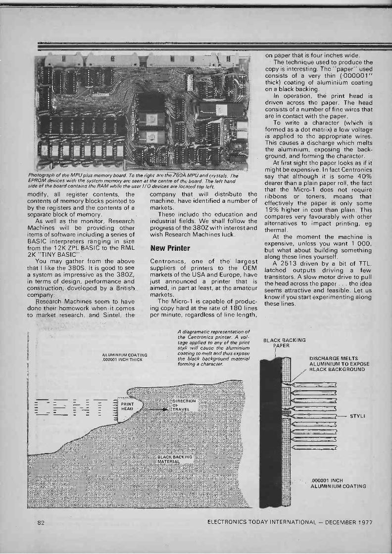
Photograph of the MPU plus memory board. To the right are the Z80A MPU and crystals. The EPROM devices with the system memory are seen at the centre of the board. The left hand side of the board contains the RAM while the user I/O devices are located top left.
modify, all register contents, the contents of memory blocks pointed to by the registers and the contents of a
separate block of memory. As well as the monitor, Research
Machines will be providing other items of software including a series of BASIC interpreters ranging in size from the 12K ZPL BASIC to the RML 2K "TINY BASIC".
You may gather from the above that I like the 380S. It is good to see a system as impressive as the 380Z, in terms of design, performance and construction, developed by a British company.
Research Machines seem to have done their homework when it comes to market research, and Sintel, the
ALUMINIUM COATING .000001 INCH THICK
company that will distribute the machine, have identified a number of markets.
These include the education and industrial fields. We shall follow the progress of the 380Z with interest and wish Research Machines luck.
New Printer
Centronics, one of the largest suppliers of printers to the OEM markets of the USA and Europe, have just announced a printer that is aimed, in part at least, at the amateur markets.
The Micro -1 is capable of produc- ing copy hard at the rate of 180 lines per minute, regardless of line length,
A diagramatic representation of the Centronics printer. A vol- tage applied to any of the print styli will cause the aluminium coating to melt and thus expose the black background material forming a character.
on paper that is four inches wide. The technique used to produce the
copy is interesting. The "paper" used consists of a very thin (000001" thick) coating of aluminiúm coating on a black backing.
In operation, the print head is driven across the paper. The head consists of a number of fine wires that are in contact with the paper.
To write a character (which is formed as a dot matrix) a low voltage is applied to the appropriate wires. This causes a discharge which melts the aluminium, exposing the back- ground, and forming the character.
At first sight the paper looks as if it might be expensive. In fact Centronics say that although it is some 40% dearer than a plain paper roll, the fact that the Micro -1 does not require ribbons or toners, means that effectively the paper is only some 19% higher in cost than plain. This compares very favourably with other alternatives to impact printing, eg thermal.
At the moment the machine is expensive, unless you want 1 000, but what about building something along these lines yourself.
A 2513 driven by a bit of TTL, latched outputs driving a few transistors. A slow motor drive to pull the head across the paper ... the idea seems attractive and feasible. Let us know if you start experimenting along these lines.
BLACK BACKING PAPER
DISCHARGE MELTS ALUMINIUM TO EXPOSE BLACK BACKGROUND
.000001 INCH ALUMINIUM COATING
82 ELECTRONICS TODAY INTERNATIONAL - DECEMBER 1977

More Bubble Less Squeak Just a very brief mention of the new additions to the Texas range of "Silent 700" printers, the 765 and 763.
While not of much immediate interest to the amateur at a couple of thousand pounds each, I mention these machines because they are the first commercial application of bubble memory.
Use of the TBM0103 bubble chip gives these terminals in their standard form 20K bytes (expandable to 80K) of non-volative storage.
This enables the terminals to have a powerful resident assembler and still leave plenty of user memory available.
Complete with thermal printer and, in the case of the 765, Texas see a wide range of applications for these machines.
Roll on the day when we US amateurs can afford to buy bubbles.
SERT-enly Interesting
The "Microprocessor Systems And Software" symposium organised by the Society of Electronic and Radio
Technicians (SERT) at the end of September was of interest to the many delegates from all over the country who enjoyed the three days at the University of Kent.
I shall report in detail on the symposium next month but shall just mention a new type of MOS technology revealed at the conference.
Page 41 of the delegates handbook referred to HMSO technology: what's that about stationary memories.
PS. For HMSO read HMOS, an Intel development in MOS design.
Change of Title
My official title at ETI, as shown on the contents page, is Editorial Assistant. Now there are a number of ways of abbreviating this title, Ed. Asst. being the most common.
The other day though, I got a letter which came up with a way of shortening the title, which the unkind may say has a ring of truth about it, but which does not appeal to me.
The label is reproduced below.
G. I. Evans Editorial Ass. E.T.I. 25-27[,1. Oxford Street London WIR 1RF
Learning To Be Sorry Finally, an apology. The "Algo- rithm Writer's Guidé" mentioned in October is no longer available from Longmans but can be obtained only from Cambridge Learning Enterpri- ses, who advertise on our pages. ET
For further details of the 380Z or the Centronics printer contact: -
OR
Research Machines P.O. Box 75, Oxford.
Centronics U.K, Petersham House, Harrington Road, London, SW7 3HA.
Respectively.
B. BAMBER ELECTRONICS CASH WITH ORDER. (MINIMUM ORDER £2.00)
PLEASE ADD VAT AS SHOWN DEPT. ETI, 5 STATION ROAD, LITTLEPORT, CAMBS. CB6 1QE POST PAID (UK ONLY), SAE WITH ENQUIRIES Tel. ELY (0353) 860185 (Tues. to Sat.) CALLERS WELCOME BY APPOINTMENT ONLY
A MERRY XMAS TO ALL OUR CUSTOMERS
PLUS AN XMAS PRESENT FROM US
in the form of a
10% DISCOUNT on all orders received from
1st to 31st December. for items in our current ads and lists only.
This offer is for 1 month only!
ALL BELOW - ADD 8% VAT RED LEDs (Min type) 5 for 70p. VIDICON SCAN COILS (Transistor type, but no data). complete with vidicon base E6 50 each Brand new.
FULL RA,,i 5 OF BERNARDS. BABINI ELECTRONICS BOOK IN STOCK S A E FOR LIST
A NEW RANGE OF QUALITY BOXES & INSTRUMENT CASES
Aluminium Boxes with Lids A810 51/4 x4x1 Y, AB13 6,4,2 AB14 7,5,2/, AB15 8x6x3 AB16 10x7x3 AB17 tOx41/4x3 A825 6.4,11
Vinyl Coated Instrument Cassa Blue Tops with Whits Lower Sections
very .man finish WB1 . . 5x21/2x21/4 .. . . .
WB2 . . . 6x4'hx11/4 .. .
WB3 . . . 8x5x2 W84 . . 9x51/4x21/2 WB5... 11x6'/.x3 . ... WB6 . - . 11x71/2x31/2 WB7 . . . 12,6x51/4 W8853 . 8,5V1/2,31/2
60p 80p
E 1.00 £1 30 £1.50 £1 30 £1.00
60p £1 10 E1.60 £1 80 £200 £2.25 E2.60 £2 00
PLASTIC PROJECT BOXES, with screws on lids (In black ABS) With brass inserts
Type NB1 approx. 3" o 21/4" x 11/2" 40p each. Type NB2 approx. 31/2" x 21/4 x 11/2" 50p. Type NB3 approx. 41/2" x 3'h" x 11/2" 60p each. Other sizes available shortly. Slider Switches 2 pole make and break (or can be used as
1 ole
change -over by linking the two centre pins/ 4 for 50
ALL BELOW - ADD 8% VAT OSMOR REED RELAY COILS (for reed relays up to
'/." dia., not supplied), 12V, 500ohm coil, 2 for 50p.
PERSPEX TUNER PANELS (for FN Band 3 -tuners), marked 88-108MHz and Channels 0-70, clear numbers, rest blacked out, small modern appearance, size approx. 81/2" x 11/4", 2 for 35p.
MIXED COMPONENT PACKS. Containing resistors. capacitors, switches, pots, etc. All new, and hundreds of items. £2.00 per pack, while stocks ast.
PROGRAMMERS (magnetic devices) contain 9 micro -switches (suitable for mains operation) with 9 rotating cams, all individually adjustable. Ideal for switching disco lights, displays, etc., or industrial machine programming (need slow motion motor to drive cams, not supplied), 9 -switch version. £1.50.
PLUGS AND SOCKETS BNC PLUGS (ex. equip.), five for £1.50. N -TYPE PLUGS, 50ohm 60p each, 3 for £1.50. Greenper (0E300015) Chassis Lead Terminations_
(Theseare the units which bolt on to the chassis, the lead is secured by screw cap. and the inner of the coax passes through the chassis), 30p each. 4 for £ 1.00.
PL259- Plugs (PTFE) brand new. packed with reducers 65p each.
S0239 Sockets (PTFE), brand new (4 -hole fixing type), 50p each.
VALVES QQV03/20A (ex. equipment). £3.00. QGV03/10 (ex. equipment), 75p or 2 for £1.20. 6BH6 (ex equipment). 2 for 50p. All the above valves are untested, except for heaters.
and no guarantee of percentage of emission is given. Sorry, no returns.
MOLLARD 85A2 65V STABILISER VALVES (brand new) 70p each of 2 for £1.20.
68W6 brand new 85p each or 2 for £1.50. TRANSISTORS PNP Audio Type Transistors. 12 for 25p. BEY51 Transistors. 4 for 60p. BYX3B/300 Stud Rectifiers. 300V at 2.5A. for for
60p. BCY72 Transistors. 4 for 50p. BSX20 (VHF osc/mull.). 3 for 50p. BC 108 (metal can ). 4 for 50p. PBC108 (plastic 8C108), 5 for 50p. BF152 (UHF amp/mixed), 3 for 50p. 2N3819 Fat.. 3 for 60p. BCl48 NPN SILICON. 4 for 50p BC158 PNP SILICON, 4 for 50p BAY3I Signal Diodes. 10 for 35p. BAY21 Varicap Diodes. 4 for 50p 741CG RCA OP Am .s 4 for £1 00
ALL BELOW - ADD 8% VAT DIECAST BOXES We stall stock these but, owing to - frequent pnce rises from our strpphers, and costly
postal charges. it has been found impossible to publish up-to-date pecan on these items. Please ring or write (with SAE) fit latest mad order prices.
AEI CS 108 R MICROWAVE DIODES. up to X -Band, max noise figure 8 5dB at 9 375GHz. 80p each
14-DIL REED RELAYS 5 to 12V DC, 450 ohm coil ./esigned to work directly from TTL Logic Single Pole changeover Contact ratings, 28V, V.A. 3W. E1.75
SPIRALUX iv, Eiaction.,... enthusiast SAE for
4MH" SIAL PACKS' 10 assoned xtals between 4MHz and 5MHz) Our selection only El. 00 pack. nc
till JT'f RELAYS. 24V DC operated tiro work un
ALU -SOL ALUMINIUM SOLDER (made by Multi -core). I aVi 3 neavy duty make contacts (around t0A aluminium to itself or copper. brass, steel.
rating) + 4 change -over contacts + 1 break contact. nickel or tinplate t6SWG with Multitore flux with New. complete wnh mounting bracket.
(idea) for instructions. approx 1m cod, 40p pack. Large reel swathing HT on Lmears. Many uses for this high ,275 Cuamyumt E1 50each
SOLDER SUCKERS [Plunger Type) Standard Model L5 00. Skirted Model. £5 50. Spare Nozzles. 60p each.
MULTICORE SOLDER bee 5 Snobs 18SWG, in alloy dispenser. 32p
'xKg (1 tlb ) 60 40 20 SWG on plastic reel, L3 00. WELLER W60D Mains operated Temperature control.
soldering Iron E 13 80. SPARE TIPS dor W600) Two types available. TYPE
CC7 íW600) Standard TYPE AA7 (W600). Finer tip. 11 15 each
Sliner Sc,ircnes 2 pole make and break (or can be used es t ,wie cnage-over by linking the two Centre pins). 4 tin 50p
ALL BELOW - ADD 8% VAT TIN SNIPS. 7". £2.25. SLIM OPEN ENDED SPANNER SETS, 0+3. 1+2.
2+4, 3+5, 4+6. 6+8BA SIZES, £1.15, MIDGET OPEN ENDED SPANNER SETS
./+1. 2+2, 3+5. 4+6. 6+86A SIZES. £2.85 set of 5 4+4.5. 5+5.5. 4+6, 6+7. 8+9. 10+11 MM SIZES. £3.50 set of 6.
MINIATURE WATCHMAKERS SCREWDRIVER SETS. L l.50 set of 5.
MINIATURE FILE SETS, set of 8 £1.90. Set of 10 L3.25 (Round. flat. etc.).
TAP AND DIE SETS (1 B -piece) contain 1 each 010. 2, 4. h 8. BA SIZES IN Dies, Plug taps. Taper Taps + amencan Type tap wrench. T -type tap wrench. Die Holder. £11.60.
TUBULAR HACKSAW FRAMES Iwith Blade/ r 2 75
A RANGE OF DRAPER TOOLS FOR THE ELECTRONICS ENTHUSIAST GOODQUAL1TY TULLY GUARANTEED(
r,1iiN5 (ESTER SCREWDRIVERS, 100 to 50017 ze 505 Large 70p
..JIO PLIIER5 5'.3" LI 60 61/4" £1 60 Di -GONAL SIDE CUTTERS. 61/4" E 1 90. SMALL SIDE CUTTERS. LJ2 Standard £3 70. U 7 iwitn wire holding device). £4 10. -LAT NOSE TOP CUTTERS, LJ 1 L4. 10. COMBINATION PLIERS 6'/e" I 1 75 7" f 1.80
ALL BELOW - ADD 12'/2 % VAT
VARICAP TUNERS. 'Mullard type, ELC1043/05. Brand new. £4.40.
TV Plugs (metal type), 4 for 50p. TV Sockets (metal type), 4 for 50p. TV Line connectors (back-to-back ski.), 4 for 50p. 3 -pin Din Plugs, 4 for 50p. Din 3 -pin Line Sockets, 15p each. Din Speaker Skts. 2 -pin, 4 for 30p.
Dubilier Electrolytics, 509 F 450V, 2 for 50p. Dubilier Electrolytics, 100,F 275V, 2 for 50p. Plessey Electrolytics, 470,F 63V, 3 for 50p. TCC Electrolytics, 1000,F 30V, 3 for 60p. Dubilier Electrolytics 5000,F 35V, 50p each. Dubilier Electrolytics, 5000,F 50V, 60p each, ITT Electrolytics, 6800,F 25V, high grade, screw
terminals, with mounting clips, 50p each, Resistor PIES. approx 300 pieces Yx to 2 watt types.
mixed values, our selection, £1.00 each -
A RANGE OF CAPACITORS AVAILABLE AT BARGAIN PRICES. SAE FOR LIST.
ELECTRONICS TODAY INTERNATIONAL - DECEMBER 1977 83

EIECTROflICS TOMORROW
by John Miller - Kirkpatrick
NOW THAT TEXAS and some other companies are committed to the 2716 type of 1 6Kbit PROM, already other companies are working on 32K and 64K bit ROMs. In an 8 bit MPU application the 64Kbit ROM would deliver 8Kbytes of program storage, about that needed by a reasonably complex BASIC interpreter or Assembler. In fact National hope to release a 64Kbit ROM for use with their SC/MP MPU, the ROM will contain NIBL (SC/MP BASIC) and SUPACC (ASSEM- BLER) plus a text editor and other programs in one chip. Price and delivery of this unit are at present unknown but I would expect to see it early next year at £100 -plus or minus a tenner.
ROM To Manoeuvre
This idea of using larger and larger ROMs for storage of main operating programs such as a large monitor or compiler has started some interesting races in the USA between Microcomputer manufacturers. Several micros are now appearing with BASIC and a BASIC driven operating system in ROM form rather than the usual 512 or 1K byte bootstrap monitor. This means that a
system can be written to communicate intelligently with the operator from power on, no more tedious single character question and answer games to indicate your wants, the MPU will now talk in a much more intelligible manner.
The alternative to the ROM system is the 1K or so bootstrap program similar to ETIBUG. This allows loading of data into the MPU by hand or machine. The data may well be a BASIC or a more complex operating system and after it is loaded it will leave you with an MPU very similar to operate to the ROM based unit mentioned earlier.
With chip manufacturers also working on larger and lower cost RAMs the relative position may well re -reverse themselves soon and leave us with an MPU with a 16K bootstrap in ROM and 44K and RAM for programs and data. I seem to remember that 44K was the minimum core required to run F level PL1 on an IBM360, within a couple of years you will be able to buy an MPU system with that specification for under £2000.
General Instruments products have for a long time been designed with product growth in mind, if you glance through their catalogue you will notice that in
several ICs there are pins which are uncommitted. These pins may be used in newer versions of the original to add new features without disrupting the downward compatability of the chip. An example is the AY -5-8300 TV games chip which has now been upgraded to give additional features without making it incompatible with PCBs designed for the original chip.
Dotty Over Paddles
On the subject of TV games, several manufacturers have started making TV games with plug in cassette reprogramming facilities. These units should become commercial practicalities next year and be in the under £100 market in time for Christmas 78. Most of these will be the big brothers of the paddle type of game available now. With the ability to program players sizes and handicaps, background layouts for different games and extras such as obstacles in a race game, the new third generation of TV games should be a lot more interesting than the present 5 or 6 game chips.
This type of games unit relies on the definition of players and obstacles which are relatively large, about 1/4
to 1/2 inch on a large TV screen - corresponding to a "dot" frequency of 1 or 2 MHz. Most VDU systems, such as that used in System 68, rely on a "dot" frequency in the range 6-20MHz or pinhead size on a normal TV screen.
This second type of TV display unit is more usually seen coupled with MPU systems than with TV games. The question is, where is the cross -over point between the two types of system? MPU based computer systems in the USA show TV games as a major selling point yet the systems are capable of much more than TV games. Most TV games played on this type of unit fall into the 'Star Trek' category, ie simple management games with text as a means of communication. The former type of games unit plays the 'Tank war' category where hand to eye co-ordination is relayed back to the games unit via a potentiometer. Although some of the newer American MPU systems such as Apple II or the Noval 760 allow for potentiometer inputs the games are slower than the TV Tennis type of game.
Graphically Game
If we assume that GI's new TV games chip allows for a combination of both graphics and text games then we may see a new style of TV games unit by this time next year. Imagine a chess trainer with text as an I /0 medium and graphics to show a representation of the board, this uses the graphics facility to denote the chess pieces and character generators to display the move requests, game history and MPU comments.
Once TV games get to this point they become educational tools, chess was used as an example above but the trainer could equally well have handled maps for geography, mechanics for maths, molecular diagrams for chemistry or simple drawings for the three Rs. Several educational material manufacturers are currently looking at the applications of MPUs in education and this type of TV games unit could be used in schools in the 1 980s.
School homework always has been a chore with probably more effort being put into ways of avoiding it than goes into doing it. Imagine going into school with an excuse like, "Sorry, sir, I couldn't do my homework because my Dad was watching Nation- wide on the TV"!
ELECTRONICS TODAY INTERNATIONAL - DECEMBER 1 977 85

o +10V
OV
O
14
10k
10k
1n
13 12 11 10
IC1
22M
150k
X1
20p
NOTE:
IC1 IC2 IC3
IS 4011 IS 4024 IS 4082
30uS 30uS
2.24mS-+ 2.24mS-+
14 12 11
IC2
1 2 3 6 7
14 13 12 10 9
IC3
1 2 3 4
A perfect ... .
JSB Dick.
As any orchestral player knows, a
source of 440 Hz, perfect or standard A is essential if he is to be in tune. On
many occasions a piano will not be available- hence this circuit.
In the following a standard crystal at 32.768 kHz is used to stabilise an oscillator. This frequency is then divided by 149 and doubled to give 439.8 Hz, an error of only 0.05% !I!
O OUTPUT
O To enable a division of 149 to be
obtained, a dual AND gate is used. The first gate detects the 149th pulse, and the second resets the binary counter on the 150th pulse
The resulting 30us pulse may be fed to a suitable amplifier
One of the more irritating aspects of owning a stereo system is the need to keep both channels in balance. What often sounds right when adjust- ing the controls turns out wrong
when resuming one's normal listening position.
This circuit offers a solution to this problem provided that one's equipment is fitted with a stereo/mono mode switch.
IC1, a 741 op amp, is used as a
differential amplifier. L and R signals are taken from across the speaker terminals. D1 and D2 rectify these and the resulting dc voltages are applied to the inputs of the IC.
The output voltage from the IC1 is applied to the LED's D3 and D6 via the current limiting resistors R7 and R8, and the diodes D4 and D5. These latter components allow the
LED's to extinguish at extremes of the IC's voltage swings.
To use the indicator, switch the
Stereo Balance Meter JP Macaulay
amplifier into the mono mode and adjust the the balance control until both LED's are equally illuminated.
OA91
C2 D2 10u 0A91
R1 10k
R2 1k
The amplifier can now be switched back into stereo mode and will be found to be in perfect balance.
R4 100k
C
R5 39k
o +9V, 16mA
,~ TIL209
D4 1N4001
R7 620R
Ró 620 R
D5 1N4001
D6 TI L209
0V o
86 ELECTRONICS TODAY INTERNATIONAL - DECEMBER 1977

Cheapo Down Counter AF Bush
This circuit, when presented with a 4 bit binary number in the range 0000-1001 will present the nines complement of that number at the output.
Connecting the circuit between a
7490 and a 7447, will, instead of the usual up count, provide a display which counts down from nine.
This provides a useful alternative to the expensive 74192 when only a down count is required.
NPN-PNP Indicator F Read
The first 2 inverters 'Cie and IC1b form a multivibrator running at approximate- ly 2 kHz. The next two inverters buff- er the multivibrator outputs, which
then go to the collector and emitter of the transistor under test.
The signal applied to the base of the transistor is always in phase with the collector so the transistor, whether PNP or NPN, will always be turned fully on every half cycle.
When an NPN transistor is being tested the collector will always be near OV and when a PNP transistor is being tested the emitter will always be near OV.
The last two inverters detect which terminal is held at OV and drive the appropriate LED via the current limit- ing resistors R4 and R5. The six inverters needed are all con-
tained in a single IC package - the SN7404.
13
R1 2k2
y C1 100n
TO PIN 7, IC1 -Ve
R2 2k2 C2
100n
IC1a
IC1b
Tech -Tips is an ideas forum and is not aimed at the beginner. We regret we cannot answer queries on these items.
ETI is prepared to consider circuits or ideas submitted by readers for this page. All items used will be paid for. Drawings should be as clear as possible and the text should preferably be typed. Circuits must not be subject to copyright. Items for consideration should be sent to ETI TECH -TIPS, Electronics Today International, 25-27 Oxford St., London W1 R 1R F.
AO
IC1a-d
IC1f D6
BCD COUNT
INPUTS OUTPUTS COMPL- EMENT D C BA QD 4c 4B QA
0 0 0 0 0 1 0 0 1 9
1 0 0 0 1 1 0 0 0 8
2 0 0 1 0 0 1 1 1 7
3 0 0 1 1 0 1 1 0 6
4 0 1 0 0 0 1 0 1 5
5 0 1 0 1 0 1 0 0 4
6 0 1 1 0 0 0 1 1 3
7 0 1 1 1 0 0 1 0 2
8 1 0 0 0 0 0 0 1 1
9 1 0 0 1 0 0 0 0 0
O OA
IC1=SN7404 D1 -9=1N4148
OA=P`
OB -g - 0c=(8 _C)_(BC)
OD=B-CD
12 11
3
IC1c 10
R3 1k
PNP R1
134
330R
NOTE: IC1 IS TO PIN 14, IC1 +Ve
SN7404 t NPN
115 330R LED2
ELECTRONICS TODAY INTERNATIONAL - DECEMBER 1977 87