Embed Size (px)
Citation preview

AVAPS Elec load analy Rev A.doc
National Center for Atmospheric Research Electronic GPS Dropsonde System Installation Electrical Loads Analysis Report: ELA-AVAPS-100 NSF Gulfstream V Aircraft, SN 677 Revision: A (initial release) Date: 25 October 2005 National Center for Atmospheric Research Research Technology Facility 3450 Mitchell Lane Boulder, Colorado 80307 Prepared By: Terry Hock Engineer National Center for Atmospheric Research
© 2005 University Corporation for Atmospheric Research Disclosure of information contained herein may only be made to UCAR or FAA personnel and/or
Designees to support this certification effort. Disclosure to other persons requires the express written consent of UCAR Legal Counsel.

Report ELA-AVAPS-100 Rev A, Initial release
UCAR Confidential and Proprietary Information
ii
Electronic GPS Dropsonde System Rack Installation Electrical Loads Analysis Report: ELA-AVAPS-100
Revision
Revision Date Description Pages Approved Date A 25 Oct 05 Initial Release All

Report ELA-AVAPS-100 Rev A, Initial release
UCAR Confidential and Proprietary Information
iii
NCAR Dropsonde System Electrical Loads Analysis
NSF Gulfstream V Aircraft, SN 677
TABLE OF CONTENTS
1. INTRODUCTION............................................................................................1
2. DESCRIPTION...............................................................................................1 2.1. RESEARCH SYSTEM ........................................................................................................... 1 2.2. RESEARCH EQUIPMENT...................................................................................................... 1 2.3. CIRCUIT PROTECTION ........................................................................................................ 2 2.4. LOAD ANALYSIS ................................................................................................................. 2
3. CONCLUSION ...............................................................................................3
LIST OF TABLES Table 1 Dropsonde Equipment List...................................................................................2 Table 2 Circuit Breaker Data.............................................................................................2 Table 3 Power Load Summary..........................................................................................3
LIST OF FIGURES Figure 1 Block diagram of power distribuiton for HAIPER Dropsonde Instrument............4

Report ELA-AVAPS-100 Page 1 of 4 Rev A
UCAR Confidential and Proprietary Information
1. Introduction
NCAR is developing main cabin equipment (MCE) racks to support atmospheric research equipment installations on the National Science Foundation (NSF) GV aircraft, SN677, under STC project number ST3285DE-T through the DOT-FAA Denver ACO. Research power wiring was previously installed by Lockheed Martin Aircraft Company IAW STC ST03056AT. Research equipment will not interface with existing aircraft systems, nor will the equipment provide information to the flight crew to assist them with operation of the aircraft. Therefore, AC 25-10 (Guidance for the Installation of Miscellaneous, Non-required Electrical Equipment) will be utilized to show compliance with the applicable regulations of 14 CFR Part 25. This report will present the data for the electrical load analysis of the Dropsonde Instrumentation rack. This report is for the electrical load analysis for the Dropsonde System atmospheric instrumentation equipment installed in an instrumentation rack in the main cabin area. Items installed in the rack are Commercial Off The Shelf (COTS) equipment. There are four items which use aircraft power; 1) PC Rack Mount Computer, 2) LCD Flat Panel Monitor, 3) Telemetry chassis and 4) 28 volt Power Supply. All equipment in the Dropsonde instrumentation rack does not interface with existing aircraft systems, nor do they provide information to the flight crew to assist them with operation of the aircraft. Therefore, the miscellaneous, non-required electrical equipment and the guidance of AC 25-10 have been utilized.
2. Description
2.1. Research System
The research electrical system is designed to provide 40KVA of 115 VAC 400HZ 3 phase power continuously from the two Integrated Drive Generators (IDGs) for research applications. Twenty KVA from each IDG is allocated for Mission power. The aircraft uses frequency converters located in the Main Power Distribution Box (MPDB) to convert the 400 HZ to 21KVA of 110 VAC 60 HZ 1 Phase as supplied by the manufacturer. Research power distribution and controls are located in the MPDB as supplied by the manufacturer. The maximum allowable continuous electrical load for each power source is 20 amps.
2.2. Research Equipment
The Dropsonde system consists of the following equipment:
• Dropsonde instrumentation rack using 115 VAC 60 Hz @14.7 amps. The unit is protected by the existing CB#3303CD11, a 20 amp breaker located in the MPDB. Table 1 lists the individual components contained in the dropsonde instrument rack. Several of the units are protected by an independent circuit breakers, see table 2.
• Dropwindsonde Launcher Assembly, manufactured by Aeromet/L3 Communications Inc., model number 01901-10101-501. The unit is powered by 28 Vdc from the Dropsonde instrumentation rack. The wiring

Report ELA-AVAPS-100 Page 2 of 4 Rev A
UCAR Confidential and Proprietary Information
harness between the instrumentation rack and launch tube is protected by a DC 20 amp circuit breaker located in the Dropsonde instrument rack.
• UHF Aircraft blade antenna, Manufactured by Sensor Systems Inc., model number S65-1217. This is a passive device and does not consume power.
The Dropsonde research instrumentation rack consists of the following commercial off the shelf (COTS) equipment: listed in Table 1
Table 1 Dropsonde Equipment List
Item Description Manufacture Model Input Voltage 1 PC Computer PCS 2USCP43 120VAC 60Hz 2 LCD Monitor Interlogic Industries RDF19AX-SHB 120VAC 60Hz 3 Telemetry Chassis/Cooling Fan NCAR AVAPS Chassis 120VAC 60Hz 4 28Vdc Power Supply Vicor VP-F1311991 120VAC 60Hz 5 Launch tube control Panel NCAR Dwg No 67705-
AVAPS-1-3 28 Vdc
6 Keyboard Cyber Research OIX 1910B-P NA 7 Sonde Storage box NCAR Dwg No. 67705-
AVAPS-1-3 NA
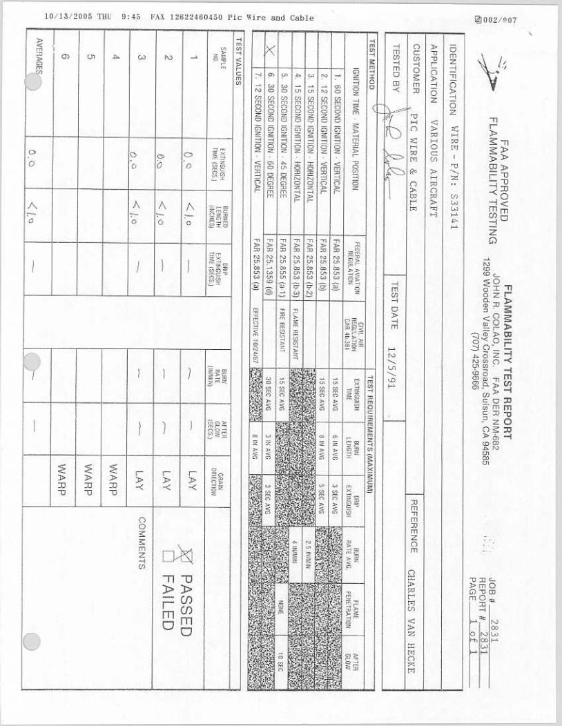
A block diagram (Dwg. No. AVAPS-100-01) of the AC and DC power system is included at the end of the report of the Dropsonde installation.
Table 2 Circuit Breaker Data
Item Description Circuit Breaker Rating Mill-Spec Part No.
1 Cooling Fan 2 amps MS3320-2
3 Telemetry Chassis 1 amps MS3320-1 4 Vicor Power Supply 5 amps MS3320-5
2.3. Circuit Protection
The equipment rack installed is individually protected by circuit breakers or by a shared breaker installed by the manufacturer in the MPDB, the breaker shall not exceed 20 Amps. The circuit breakers are of the same type as installed by the manufacturer as original equipment.
2.4. Load Analysis Below in table 1 is a list of all devices in the Dropsonde Instrumentation rack that is power by the aircraft 110 VAC 60Hz power system. The equipment has built in circuit breaker protection for each individual item listed in table 1. The maximum total current load under any condition is 11.7 amps.

Report ELA-AVAPS-100 Page 3 of 4 Rev A
UCAR Confidential and Proprietary Information
Table 3 Power Load Summary
Tabulation of power values AC Power 120VAC @ 60 Hz for all units listed
Item Description AC Power Cable Type
Average Current (Amps)
Peak Current (Amps)
Power Not to Exceed (Watts)
Unit Circuit Breaker (Amps)
1 Computer 3-wire 16 gauge
0.8 1.3 350 None
2 Monitor 3-wire 16gauge
0.4 0.4 50 None
3 Telemetry Chassis/ Cooling Fan
3-wire 16 gauge
0.5 0.7 100 2
4 Vicor Power Supply
3-wire 16 gauge
0.3 3.5 500 5
Total 2.0 Amps 5.9 Amps 1000 Watts 7 Amps The maximum electrical load current at 120VAC 60HZ of the Dropsonde Instrument rack is 5.9 amps. This load allows for a safety margin of 14.1 amps (or 70.5 %) from the 20 amp circuit for the MCE.
3. Conclusion The basic research rack system as installed by NCAR is a stand alone independent system that interfaces to the Lockheed Martin Aircraft Center as part of STC number ST03056AT research electrical system. This research power distribution system incorporates automatic load shedding and a cockpit kill switch for the research power system. Independent circuit breakers protect all of the rack installed equipment and are of the type supplied as original equipment by the manufacturer. The system loads cannot exceed 20 amps per circuit. All the circuit breakers are accessible to the flight crew at the Main Power Distribution Box. The basic research systems do not interface with existing aircraft systems, nor do they provide information to the flight crew to assist them with operation of the aircraft. Therefore, all basic research system equipment can be considered miscellaneous, non-required electrical equipment and the guidance of AC 25-10 has been utilized.

Report ELA-AVAPS-100 Page 4 of 4 Rev A
UCAR Confidential and Proprietary Information
Figure 1 Block diagram of power distribution for HIAPER Dropsonde Instrument

D
C
B
A
4 3 2 1
D
C
B
A
4 3 2 1
Copyright © 2005 University Corporations for Atmospheric Research, All rights reserved.
CONFIDENTIAL, Any unauthorized use, coping or distribution is prohibited.
ENG: T. Hock 9/2/05
National Center for Atmospheric ResearchEarth Observing Lab
3450 Mitchell Lane, Boulder CO 80307
HIAPER Dropsonde Power Distribution Block Diagram
SIZE FSCM NO DWG NO REV
A HAIPER ELA Diagram Rev A 677AVAPS-100-01 A
SCALE 1 : 1 SHEET 1 OF 1
File Name:
REV. DESCRIPTION DATE BYA Initial Release 9/2/05 TFH
20 Amp
PCS ComputerModel No. 2USCP43
LCD MonitorModel No. RDF19AX-SHB
NCAR DropsondeTelemetry Chassis
Power Supply 28Vdc Model No.
Vicor VP-F1311991
NCAR Dropsonde Telemetry Fan Unit
Dropwindsonde Launcher Assembly
Part No. 01901-10101-50128 Vdc
120 VAC 60 Hz
120 VAC 60 Hz
Main Power Distribution Box(Existing)
CB 3303CB11
Right Cabin SPARE
120 VAC 60 HZBreaker "A"
2.0 amp
5.0 amp
NCAR Dwg. No. 677-05-
24-103
120 VAC 60 Hz
120 VAC 60 Hz
120 VAC 60 Hz
120 VAC 60 HzA
B
C
D
E
F
REF.ABCDE
CABLE DESCRIPTIONAC Power 3-wire 16 gaugeAC Power 3-wire 16 gaugeAC Power 3-wire 16 gaugeAC Power 3-wire 16 gaugeAC Power 3-wire 16 gauge
NCAR Dwg. No.677AVAPS-3-08677AVAPS-3-08677AVAPS-3-01677AVAPS-3-03677AVAPS-3-02
POWER NOT TO EXCEED 100W
POWER NOT TO EXCEED 700W
POWER NOT TO EXCEED 50W
POWER NOT TO EXCEED 350W
POWER NOT TO EXCEED 450W
60 Hz Breakout Power Box
F DC Power 2-wire 16 gauge, 3-wire 22 gauge 677AVAPS-3-05
1.0 amp
P/N: MS3320-1
P/N: MS3320-5
P/N: MS3320-2


���
���
���
��
�
�
� � � �
� � � �
�
�
���
���
���� ������������� ��������� ���� �����
�
�������������
������������� �������������� � ��
� � ��� �� � �� � �� �� �� � �
� �
�����!�
����"� �
������������
����
����
����
�#$%& �'('�('
"����)*+,- �'(��('
�)$.& �'(��('
������ ��� ��������� �/� /������!�#01).234��''��������55�).2346�),6,)7,8�
����
�������
����
����
��'�
���
/��9��:������
��9��:����
��9�����
/��9��:���'�
�/��9��:��'�
��9��:���'�
��9��:�'
/��9��:��'��
�����:����
�����:����
��9�:���'�
��9��:�'
��9��:����
��9��:����
/��9��:���'�
/��9�:�����
/��9��:��'�
/��9��:�����
/�����:����
/���� �:���
������;����'
�� �:���
�������'
��'
����''
��'
��������
��'
����''
��'
��'
�������������� ��������
��'
��������
��'
���
���
���
��'�
��������
��'
��'
�������
������:����
��/�����"
�������� ��������
�� �9�
�� �9�
�� �9�
� ������� �/��
�����! ���
�������
� ����"�/��/5%4,
������� ������� ������� ��������
����
���� �����!
���
������� �/�������
�������
/5%4,�����#44#<
���/��%=-
���/���%=-
�&8,)��5##)
)#0��#&8,��%*&=3,)
�6,��5##)/%66��3)#*23
�55�,>*.0<,&4�.6�6*005.,8�+1�43,�*6,)��3,�?#)$%)8�)#*4,�.6�?#)�#&,�@�A�%&4,&&%�=%+5,�/(�����'��B
43,��/��=%+5,�/(���������2#,6�4#�43,��/��/5%4,�%&8�43,�%?4�)#*4,�.6�?#)�%�=#&4)#5�=%+5,�=#&6.6.4.&2�#?
43),,�@�A��.5:�:����(��:��:�B�4$#�@�A��.5:�:����(��:��:�%&8�#&,�@�A����=%+5,�/(����'��:����:'��
�/��/5%4,

D
C
B
A
4 3 2 1
D
C
B
A
4 3 2 1
Copyright © 2005 University Corporations for Atmospheric Research, All rights reserved.
CONFIDENTIAL, Any unauthorized use, coping or distribution is prohibited.
ENG: T. Hock 9/2/05
National Center for Atmospheric ResearchEarth Observing Lab
3450 Mitchell Lane, Boulder CO 80307
HIAPER Dropsonde Power Distribution Block Diagram
SIZE FSCM NO DWG NO REV
A HAIPER ELA Diagram Rev A 677AVAPS-100-01 A
SCALE 1 : 1 SHEET 1 OF 1
File Name:
REV. DESCRIPTION DATE BYA Initial Release 9/2/05 TFH
20 Amp
PCS ComputerModel No. 2USCP43
LCD MonitorModel No. RDF19AX-SHB
NCAR DropsondeTelemetry Chassis
Power Supply 28Vdc Model No.
Vicor VP-F1311991
NCAR Dropsonde Telemetry Fan Unit
Dropwindsonde Launcher Assembly
Part No. 01901-10101-50128 Vdc
120 VAC 60 Hz
120 VAC 60 Hz
Main Power Distribution Box(Existing)
CB 3303CB11
Right Cabin SPARE
120 VAC 60 HZBreaker "A"
2.0 amp
5.0 amp
NCAR Dwg. No. 677-05-
24-103
120 VAC 60 Hz
120 VAC 60 Hz
120 VAC 60 Hz
120 VAC 60 HzA
B
C
D
E
F
REF.ABCDE
CABLE DESCRIPTIONAC Power 3-wire 16 gaugeAC Power 3-wire 16 gaugeAC Power 3-wire 16 gaugeAC Power 3-wire 16 gaugeAC Power 3-wire 16 gauge
NCAR Dwg. No.677AVAPS-3-08677AVAPS-3-08677AVAPS-3-01677AVAPS-3-03677AVAPS-3-02
POWER NOT TO EXCEED 100W
POWER NOT TO EXCEED 700W
POWER NOT TO EXCEED 50W
POWER NOT TO EXCEED 350W
POWER NOT TO EXCEED 450W
60 Hz Breakout Power Box
F DC Power 2-wire 16 gauge, 3-wire 22 gauge 677AVAPS-3-05
1.0 amp
P/N: MS3320-1
P/N: MS3320-5
P/N: MS3320-2

Copyright © 2005 University Corporations for Atmospheric Research, All rights reserved.
CONFIDENTIAL, Any unauthorized use, coping or distribution is prohibited.
ENG: T. Hock 10/19/05
National Center for Atmospheric ResearchEarth Observing Lab
3450 Mitchell Lane, Boulder CO 80307
Computer Octopus Serial Cable to Telemetry Chassis
SIZE FSCM NO DWG NO REV
A 677AVAPS-3-14 A
SCALE 1 : 1 SHEET 1 OF 2
File Name:
REV. DESCRIPTION DATE BYA Initial Release 10/19/05 TFH
39"
Qty PART NO. MANUFACTURE
2 760002042F WhyteHaus Cables
A
D
C
B
A
4 3 2 1
D
C
B
A
4 3 2 1
Computer Signal Cable
REF
A
DESCRIPTION
Video Computer Cable
DB-9Female
Label ID: PC/SERIAL/A1-3-14
To: Computer DB-78 Port (#1 Lower Connector)
To: Telemetry Chassis
DB-78Male
DB-9Female
DB-9Female
DB-9Female
DB-9Female
DB-9Female
DB-9Female
DB-9Female
Label ID: PC/SERIAL/A2-3-14
Label ID: PC/SERIAL/A5-3-14
Label ID: PC/SERIAL/A6-3-14
Label ID: PC/SERIAL/A7-3-14
Label ID: PC/SERIAL/A8-3-14
Label ID: PC/SERIAL/A4-3-14
Label ID: PC/SERIAL/A3-3-14
P1: RCVR/PTU BUFFER #1
P4: RCVR/PTU BUFFER #4
P2: RCVR/PTU BUFFER #2
P3: RCVR/PTU BUFFER #3
P5: MWG #1
P6: MWG #2
P7: MWG #3
P8: MWG #4

Copyright © 2005 University Corporations for Atmospheric Research, All rights reserved.
CONFIDENTIAL, Any unauthorized use, coping or distribution is prohibited.
ENG: T. Hock 10/19/05
National Center for Atmospheric ResearchEarth Observing Lab
3450 Mitchell Lane, Boulder CO 80307
Computer Octopus Serial Cable to Telemetry Chassis
SIZE FSCM NO DWG NO REV
A 677AVAPS-3-14 A
SCALE 1 : 1 SHEET 2 OF 2
File Name:
REV. DESCRIPTION DATE BYA Initial Release 10/19/05 TFH
39"
A
Computer Signal Cable
DB-9Female
Label ID: PC/SERIAL/B1-3-14
To: Telemetry Chassis
DB-9Female
DB-9Female
DB-9Female
DB-9Female
DB-9Female
DB-9Female
DB-9Female
Label ID: PC/SERIAL/B2-3-14
Label ID: PC/SERIAL/B5-3-14
Label ID: PC/SERIAL/B6-3-14
Label ID: PC/SERIAL/B7-3-14
Label ID: PC/SERIAL/B8-3-14
Label ID: PC/SERIAL/B4-3-14
Label ID: PC/SERIAL/B3-3-14
D
C
B
A
4 3 2 1
D
C
B
A
4 3 2 1
P9: Telemetry Log Rcvr
DB-78Male
P10: Sonde Interface
P105: MWG FSK DEMOD #1
P106: MWG FSK DEMOD #2
P107: MWG FSK DEMOD #3
P108: MWG FSK DEMOD #4
Null Modem (DM9 male)
Null Modem (DM9 male)
To: Computer DB-78 Port (#2 Upper Connector)

Copyright © 2005 University Corporations for Atmospheric Research, All rights reserved.
CONFIDENTIAL, Any unauthorized use, coping or distribution is prohibited.
ENG: T. Hock 10/19/05
National Center for Atmospheric ResearchEarth Observing Lab
3450 Mitchell Lane, Boulder CO 80307
Keyboard/Mouse Cable
SIZE FSCM NO DWG NO REV
A 677AVAPS-3-13 A
SCALE 1 : 1 SHEET 1 OF 1
File Name:
REV. DESCRIPTION DATE BYA Initial Release 10/19/05 TFH
42"
Qty PART NO. MANUFACTURE
1 DU-5K Ikeu
A
D
C
B
A
4 3 2 1
D
C
B
A
4 3 2 1
Computer Signal Cable
DB-15Male
REF
A
DESCRIPTION
Keyboard/Mouse Computer Cable/Keyboard
PS-2Male
Label ID: PC/KBD&MOUSE-3-13
PS-2Male
Green
To: Computer Keyboard Plug
To: Computer Mouse Plug
Pink
Note: Apply label ID within 6" of each end and at 5' increments

Copyright © 2005 University Corporations for Atmospheric Research, All rights reserved.
CONFIDENTIAL, Any unauthorized use, coping or distribution is prohibited.
ENG: T. Hock 10/19/05
National Center for Atmospheric ResearchEarth Observing Lab
3450 Mitchell Lane, Boulder CO 80307
Computer Video Monitor Cable
SIZE FSCM NO DWG NO REV
A 677AVAPS-3-12 A
SCALE 1 : 1 SHEET 1 OF 1
File Name:
REV. DESCRIPTION DATE BYA Initial Release 10/19/05 TFH
60"
Qty PART NO. MANUFACTURE
1 EVNPS06-005-MM Black Box Network Services.
A
D
C
B
A
4 3 2 1
D
C
B
A
4 3 2 1
Computer Signal Cable
REF
A
DESCRIPTION
Video Computer Cable
DB-15Male
Label ID: MONITOR/VIDEO-3-12
To: Monitor Video Port
To: Computer Video Port
DB-15Male
Note: Apply label ID within 6" of each end and at 5' increments

Copyright © 2005 University Corporations for Atmospheric Research, All rights reserved.
CONFIDENTIAL, Any unauthorized use, coping or distribution is prohibited.
ENG: T. Hock 10/19/05
National Center for Atmospheric ResearchEarth Observing Lab
3450 Mitchell Lane, Boulder CO 80307
HIAPER Dropsonde AC Power Cable, Monitor
SIZE FSCM NO DWG NO REV
A 677AVAPS-3-11 A
SCALE 1 : 1 SHEET 1 OF 1
File Name:
REV. DESCRIPTION DATE BYA Initial Release 10/19/05 TFH
54"
Qty PART NO. MANUFACTURE
1 HBL8215C Hubbell
1 STT-16 16-TE-1929(3) STJ TYPE E THERMAX
1 4781.0000 SCHURTER
A
B C
D
C
B
A
4 3 2 1
D
C
B
A
4 3 2 1
RED
BLACK
WHITE
HOT
GROUND
RETURN
120VACPOWER PLUG
AC Plug
PLUG SIDE VIEW
NOTE: SHIELD NOT USED
REF
A
B
C
DESCRIPTION
Connector, AC Power / Plug, Hospital grade, 15A/125V
3 conductor 16 gauge wire Teflon insulation
Connector, AC POWER PLUG / 3-circuit Female
Label ID: MONITOR/120VAC-3-11
Attaches To:Monitor
Attaches To:AC Power Terminal Strip
Note: Apply label ID within 6" of each end and at 5' increments

Copyright © 2005 University Corporations for Atmospheric Research, All rights reserved.
CONFIDENTIAL, Any unauthorized use, coping or distribution is prohibited.
ENG: T. Hock 10/19/05
National Center for Atmospheric ResearchEarth Observing Lab
3450 Mitchell Lane, Boulder CO 80307
HIAPER Dropsonde GPS RF Cable, Sonde Storage Box
SIZE FSCM NO DWG NO REV
A HAIPER ELA Diagram Rev A 677AVAPS-3-10 A
SCALE 1 : 1 SHEET 1 OF 1
File Name:
REV. DESCRIPTION DATE BYA Initial Release 10/19/05 TFH
12.5"
Qty PART NO. MANUFACTURE
2 190314 PC WIRE & CABLE
1 S44191 PC WIRE & CABLE
AB
A
D
C
B
A
4 3 2 1
D
C
B
A
4 3 2 1
REF
A
B
DESCRIPTION
SMA RF CONNECTORS
50 ohm COAX
RF SMA
Connector
RF SMA
Connector
Label ID: LNCHR/GPS-3-10
Attaches To:GPS AntennaAttaches To:
GPS Power Divider
Note: Apply label ID within 6" of each end and at 5' increments

Copyright © 2005 University Corporations for Atmospheric Research, All rights reserved.
CONFIDENTIAL, Any unauthorized use, coping or distribution is prohibited.
ENG: T. Hock 10/19/05
National Center for Atmospheric ResearchEarth Observing Lab
3450 Mitchell Lane, Boulder CO 80307
HIAPER Dropsonde GPS RF CABLE, Sonde Storage Box to Telemetry Chassis
SIZE FSCM NO DWG NO REV
A 677AVAPS-3-09 A
SCALE 1 : 1 SHEET 1 OF 1
File Name:
REV. DESCRIPTION DATE BYA Initial Release 10/19/05 TFH
25.75"
Qty PART NO. MANUFACTURE
2 190308 PC WIRE & CABLE
1 S44191 PC WIRE & CABLE
AB
A
D
C
B
A
4 3 2 1
D
C
B
A
4 3 2 1
REF
A
B
DESCRIPTION
TNC RF CONNECTOR
50 ohm COAX
RF TNC
Connector
Attaches To:Sonde Storage Box
Attaches To:Telemetry Chassis
RF TNC
Connector
Label ID: CHASSIS/GPS-3-09
Note: Apply label ID within 6" of each end and at 5' increments

Copyright © 2005 University Corporations for Atmospheric Research, All rights reserved.
CONFIDENTIAL, Any unauthorized use, coping or distribution is prohibited.
ENG: T. Hock 10/19/05
National Center for Atmospheric ResearchEarth Observing Lab
3450 Mitchell Lane, Boulder CO 80307
HIAPER Dropsonde AC Power Cable, COMPUTER
SIZE FSCM NO DWG NO REV
A 677AVAPS-3-08 A
SCALE 1 : 1 SHEET 1 OF 1
File Name:
REV. DESCRIPTION DATE BYA Initial Release 10/19/05 TFH
39"
Qty PART NO. MANUFACTURE
1 HBL8215C Hubbell
1 STT-16 16-TE-1929(3) STJ TYPE E THERMAX
1 4781.0000 SCHURTER
A
B C
D
C
B
A
4 3 2 1
D
C
B
A
4 3 2 1
RED
BLACK
WHITE
HOT
GROUND
RETURN
120VACPOWER PLUG
AC Plug
PLUG SIDE VIEW
NOTE: SHIELD NOT USED
REF
A
B
C
DESCRIPTION
Connector, AC Power / Plug, Hospital grade, 15A/125V
3 conductor 16 gauge wire Teflon insulation
Connector, AC POWER PLUG / 3-circuit Female
Label ID: PC/120VAC-3-08
Attach To:Computer
Attach To:AC Power Terminal Strip
Note: Apply label ID within 6" of each end and at 5' increments

Copyright © 2005 University Corporations for Atmospheric Research, All rights reserved.
CONFIDENTIAL, Any unauthorized use, coping or distribution is prohibited.
ENG: T. Hock 10/25/05
National Center for Atmospheric ResearchEarth Observing Lab
3450 Mitchell Lane, Boulder CO 80307
HIAPER Dropsonde Launcher Control Cable, to Dropwindsonde Launcher Assembly
SIZE FSCM NO DWG NO REV
A 677AVAPS-3-07 A
SCALE 1 : 1 SHEET 1 OF 1
File Name:
REV. DESCRIPTION DATE BYA Initial Release 10/25/05 TFH
Final length to be determined upon installation(Shall not exceed 30’)
Qty PART NO. MANUFACTURE
1 MS3126F14-15S ITT Cannon
1 M22759/1619WE THERMAX
1 M22759/161619WE THERMAX
AD
D
C
B
A
4 3 2 1
D
C
B
A
4 3 2 1
28 VDC ARM SOLENOID
MS CircularFemale
Connector
REF
A
B
C
DESCRIPTION
Connector, MS Circular / MIL-C-5015 15-circuit Female
1 conductor 22 gauge wire, TEFLON WHITE
1 conductor 16 gauge wire, TEFLON WHITE
ABCDEFGHIJKLMNO
MS CircularFemale
Connector
ABCDEFFG....RS
28V DC28V LAUNCH SOLENOID
GROUNDVALVE OPEN SIGNAL
C
CC
B
B
C
1 MS3126F14-19S ITT CannonD Connector, MS Circular / MIL-C-5015 19-circuit Female
Note: Apply label ID within 6" of each end and at 5' increments
Label ID: LNCHR/28VDC-3-07
Attaches To:Dropwindsonde Launcher Assembly
Attaches to 28VDC PowerSupply
B
B
B
B
B
B
5"
8"
10.5"
5"
8"
10.5"
E
E
E
E
E
E
6 BS18C 3ME Crimp wire connector, covered with heat shrink tubing

Copyright © 2005 University Corporations for Atmospheric Research, All rights reserved.
CONFIDENTIAL, Any unauthorized use, coping or distribution is prohibited.
ENG: T. Hock 10/19/05
National Center for Atmospheric ResearchEarth Observing Lab
3450 Mitchell Lane, Boulder CO 80307
HIAPER Dropsonde RF COAX CABLE, UHF ANTENNA
SIZE FSCM NO DWG NO REV
A 677AVAPS-3-06 A
SCALE 1 : 1 SHEET 1 OF 1
File Name:
REV. DESCRIPTION DATE BYA Initial Release 10/19/05 TFH
Length to be determined upon installation(Shall not exceed 75’)
Qty PART NO. MANUFACTURE
2 190410 PC WIRE & CABLE
1 S22089 PC WIRE & CABLE
AB
A
D
C
B
A
4 3 2 1
D
C
B
A
4 3 2 1
RF TYPE "N" Connector
REF
A
B
DESCRIPTION
TYPE N RF CONNECTORS
50 ohm COAX, RG-8 TYPE
RF TYPE "N" Connector
Attaches To:400 MHz UHF Blade Antenna
Attaches To: Telemetry Chassis
Note: Apply label ID within 6" of each end and at 5' increments
Label ID: CHASSIS/400MHZ-3-06

Copyright © 2005 University Corporations for Atmospheric Research, All rights reserved.
CONFIDENTIAL, Any unauthorized use, coping or distribution is prohibited.
ENG: T. Hock 9/7/05
National Center for Atmospheric ResearchEarth Observing Lab
3450 Mitchell Lane, Boulder CO 80307
HIAPER Dropsonde Launcher Control Cable, Launch Control Panel to 28VDC Power Supply
SIZE FSCM NO DWG NO REV
A 677AVAPS-3-05 A
SCALE 1 : 1 SHEET 1 OF 1
File Name:
REV. DESCRIPTION DATE BYA Initial Release 9/7/05 TFH
55"
Qty PART NO. MANUFACTURE
1 MS3126F14-15S ITT Cannon
1 M22759/1619WE THERMAX
1 M22759/161619WE THERMAX
AD
D
C
B
A
4 3 2 1
D
C
B
A
4 3 2 1
28 VDC ARM SOLENOID
MS CircularFemale
Connector
REF
A
B
C
DESCRIPTION
Connector, MS Circular / MIL-C-5015 15-circuit Female
1 conductor 22 gauge wire, TEFLON WHITE
1 conductor 16 gauge wire, TEFLON WHITE
ABCDEFGHIJKLMNO
MS CircularFemale
Connector
ABCDEFGHIJKLMNOPQRS
28V DC28V LAUNCH SOLENOID
GROUNDVALVE OPEN SIGNAL
B
C
B
B
C
1 MS3126F14-19S ITT CannonD Connector, MS Circular / MIL-C-5015 19-circuit Female
Note: Apply label ID within 6" of each end and at 5' increments
Label ID: LNCHR/28VDC-3-05
Attaches to Launch Control Panel
Attaches to 28VDC PowerSupply

Copyright © 2005 University Corporations for Atmospheric Research, All rights reserved.
CONFIDENTIAL, Any unauthorized use, coping or distribution is prohibited.
ENG: T. Hock 9/7/05
National Center for Atmospheric ResearchEarth Observing Lab
3450 Mitchell Lane, Boulder CO 80307
HIAPER Dropsonde DC Power Cable, 28 Vdc Power Supply to Launch Control Panel
SIZE FSCM NO DWG NO REV
A 677AVAPS-3-04 A
SCALE 1 : 1 SHEET 1 OF 1
File Name:
REV. DESCRIPTION DATE BYA Initial Release 9/7/05 TFH
59"
Qty PART NO. MANUFACTURE
1 CA3106E14S-6PB ITT Cannon
1 STT-16 16-TE-1929(3) STJ TYPE E THERMAX
1 CA3106E14S-6SB ITT Cannon
A B C
D
C
B
A
4 3 2 1
D
C
B
A
4 3 2 1
RED
BLACK
28 Vdc
GROUNDMS Circular
Female Connector
NOTE: SHIELD NOT USED
REF
A
B
C
DESCRIPTION
Connector, MS Circular / MIL-C-5015 6-circuit Male
3 conductor 16 gauge wire Teflon insulation
Connector, MS Circular / MIL-C-5015 6-circuit Female
A
B
C
D
E
F
MS CircularMale
Connector
A
B
C
D
E
F
Label ID: DCPS/28VDC-3-04
Note: Apply label ID within 6" of each end and at 5' increments
Attach to 28VDC Power Supply, AC Input
Attach to Launch Control Panel

Copyright © 2005 University Corporations for Atmospheric Research, All rights reserved.
CONFIDENTIAL, Any unauthorized use, coping or distribution is prohibited.
ENG: T. Hock 9/7/05
National Center for Atmospheric ResearchEarth Observing Lab
3450 Mitchell Lane, Boulder CO 80307
HIAPER Dropsonde AC Power Cable, 28 Vdc Power Supply
SIZE FSCM NO DWG NO REV
A 677AVAPS-3-03 A
SCALE 1 : 1 SHEET 1 OF 1
File Name:
REV. DESCRIPTION DATE BYA Initial Release 9/7/05 TFH
A
B
C
13"
Qty PART NO. MANUFACTURE
1 HBL8215C Hubbell
1 STT-16 16-TE-1929(3) STJ TYPE E THERMAX
1 CA3106E14S-7SB ITT Cannon
A
B C
D
C
B
A
4 3 2 1
D
C
B
A
4 3 2 1
RED
BLACK
WHITE
HOT
GROUND
RETURN
120VACPOWER PLUG
MS CircularFemale
Connector
PLUG SIDE VIEW
NOTE: SHIELD NOT USED
REF
A
B
C
DESCRIPTION
Connector, AC Power / Plug, Hospital grade, 15A/125V
3 conductor 16 gauge wire Teflon insulation
Connector, MS Circular / MIL-C-5015 3-circuit Female
Note: Apply label ID within 6" of each end and at 5' increments
Label ID: DCPS/120VAC-3-03
Attach to AC Terminal Strip
Attach to 28VDC Power Supply, AC Input

Copyright © 2005 University Corporations for Atmospheric Research, All rights reserved.
CONFIDENTIAL, Any unauthorized use, coping or distribution is prohibited.
ENG: T. Hock 9/7/05
National Center for Atmospheric ResearchEarth Observing Lab
3450 Mitchell Lane, Boulder CO 80307
HIAPER Dropsonde AC Power Cable, Cooling Fan unit to Telemetry Chassis
SIZE FSCM NO DWG NO REV
A 677AVAPS-3-02 A
SCALE 1 : 1 SHEET 1 OF 1
File Name:
REV. DESCRIPTION DATE BYA Initial Release 9/7/05 TFH
A
B
C
13.5"
Qty PART NO. MANUFACTURE
1 CA3106E14S-7PB ITT Cannon
1 STT-16 16-TE-1929(3) STJ TYPE E THERMAX
1 CA3106E14S-7SB ITT Cannon
A B C
D
C
B
A
4 3 2 1
D
C
B
A
4 3 2 1
RED
BLACK
WHITE
HOT
GROUND
RETURN
MS CircularFemale
Connector
NOTE: SHIELD NOT USED
REF
A
B
C
DESCRIPTION
3 conductor 16 gauge wire Teflon insulation
Connector, MS Circular / MIL-C-5015 3-circuit Female
A
B
C
MS CircularMale Connector
Connector, MS Circular / MIL-C-5015 3-circuit Male
Label ID: CHASSIS/120VAC-3-02
Note: Apply label ID within 6" of each end and at 5' increments
Attach to Cooling Fan
Attach to Telemetry Chassis

Copyright © 2005 University Corporations for Atmospheric Research, All rights reserved.
CONFIDENTIAL, Any unauthorized use, coping or distribution is prohibited.
ENG: T. Hock 10/19/05
National Center for Atmospheric ResearchEarth Observing Lab (EOL)
3450 Mitchell Lane, Boulder CO 80307
HIAPER Dropsonde AC Power Cable, Cooling Fan
SIZE FSCM NO DWG NO REV
A 677AVAPS-3-01 A
SCALE 1 : 1 SHEET 1 OF 1
File Name:
REV. DESCRIPTION DATE BYA Initial Release 10/19/05 TFH
A
B
C
31"
Qty PART NO. MANUFACTURE
1 HBL8215C Hubbell
1 STT-16 16-TE-1929(3) STJ TYPE E THERMAX
1 CA3106E14S-7SB ITT Cannon
A
B C
D
C
B
A
4 3 2 1
D
C
B
A
4 3 2 1
RED
BLACK
WHITE
HOT
GROUND
RETURN
120VACPOWER PLUG
MS CircularFemale
Connector
PLUG SIDE VIEW
NOTE: SHIELD NOT USED
REF
A
B
C
DESCRIPTION
Connector, AC Power / Plug, Hospital grade, 15A/125V
3 conductor 16 gauge wire Teflon insulation
Connector, MS Circular / MIL-C-5015 3-circuit Female
Note: Apply label ID within 6" of each end and at 5' increments
Label ID: FANS/120VAC-3-01
Attaches to Cooling Fan AC Input
Attaches to AC Terminal Strip
Copyright © 2005 University Corporations for Atmospheric Research, All rights reserved.
CONFIDENTIAL, Any unauthorized use, coping or distribution is prohibited.
ENG: T. Hock 9/2/05
National Center for Atmospheric ResearchEarth Observing Lab
3450 Mitchell Lane, Boulder CO 80307
HIAPER DROPSONDE INSTRUMENTATION ASSEMBLY WIRING DIAGARM
SIZE FSCM NO DWG NO REV
B AVAPS-2-02 A
SCALE 1 : 1 SHEET 1 OF 2
File Name:
REV. DESCRIPTION DATE BYA Initial Release 9/2/05 TFH
H
G
F
E
D
C
B
A
8 7 6 5 4 3 2 1
H
G
F
E
D
C
B
A
8 7 6 5 4 3 2 1
1
2
3
4
1
2
3
4
1
22
4
33
4
RCVR/PTU Buffer MWG
MWG P1 Data
MWG FSK
Demod
1
Keyboard
LCDMonitor
PCComputer
Keyboard
TelemtryChassis
CoolingFan
Video Input
AC Input
AC Input
Video
400 MHzAnt
GPS Ant
AC Input
AC Input AC Output
RJ-45 Network
Sonde Interface
Log Rcvr
To Aircraft Data System
AC Power Strip
400 MHz UHF BLADE ANTENNA
GPS RF Power Divider
GPS Antenna
Sonde Storage Box
COAX
COAX
COAX
COAXAIRCRAFT
GPS RF SIGNAL
AC Power 120VAC 60 Hz 3-wire
AC Power 120VAC 60 Hz 3-wire
AC Power 120VAC 60 Hz 3-wire
AC Power120VAC60 Hz 3-wire
Video Signal
RS-232 Signal
A
REF.ABCDEFGHIJK
Drawing Number677AVAPS-3-01677AVAPS-3-02677AVAPS-3-03677AVAPS-3-04677AVAPS-3-05677AVAPS-3-06677AVAPS-3-07677AVAPS-3-08677AVAPS-3-09677AVAPS-3-10677AVAPS-3-11
B
F
H
K
IJ
COAX
O
N
DROPWINDSONDE LAUNCHER
L
M
L 677AVAPS-3-12M 677AVAPS-3-13N 677AVAPS-3-14O 677AVAPS-3-15

Copyright © 2005 University Corporations for Atmospheric Research, All rights reserved.
CONFIDENTIAL, Any unauthorized use, coping or distribution is prohibited.
ENG: T. Hock 9/2/05
National Center for Atmospheric ResearchEarth Observing Lab
3450 Mitchell Lane, Boulder CO 80307
HIAPER Dropsonde Assembly Wiring Diagram
SIZE FSCM NO DWG NO REV
B HAIPER ELA Diagram Rev A AVAPS-2-02 A
SCALE 1 : 1 SHEET 2 OF 2
File Name:
REV. DESCRIPTION DATE BYA Initial Release 9/2/05 TFH
H
G
F
E
D
C
B
A
8 7 6 5 4 3 2 1
H
G
F
E
D
C
B
A
8 7 6 5 4 3 2 1
LAUNCH CONTROL PANEL
AC Power Strip
AC Power 120VAC 60 Hz 3-wire
C
DROPSONDE DISPENSER
28 Vdc POWER SUPPLY
MOUNTED ON REAR OF INSTRUMENT RACK
D
GTO DROPWINDSONDE
LAUNCHER ASSEMBLY
VICOR 28V SUPPLY
CONTROL PANEL
120V AC INPUT
DISPENSER28V DC OUT
MOUNTED ON REAR OF INSTRUMENT RACK
MOUNTED ON FRONT OF INSTRUMENT RACK
E

Copyright © 2005 University Corporations for Atmospheric Research, All rights reserved.
CONFIDENTIAL, Any unauthorized use, coping or distribution is prohibited.
ENG: T. Hock 10/26/05
National Center for Atmospheric ResearchEarth Observing Lab
3450 Mitchell Lane, Boulder CO 80307
HIAPER Dropsonde Instrumentation Block Wiring Diagram
SIZE FSCM NO DWG NO REV
B HIAPER Dropsonde AVAPS-2-01 Block Wiring 677AVAPS-2-01 A
SCALE 1 : 1 SHEET 1 OF 1
File Name:
REV. DESCRIPTION DATE BYA Initial Release 10/26/05 TFH
H
G
F
E
D
C
B
A
8 7 6 5 4 3 2 1
H
G
F
E
D
C
B
A
8 7 6 5 4 3 2 1
H
I
HTelemetryChassis
B
B C
Cooling Fan
LCD Monitor
Keyboard
PC Computer
28 Vdc Power Supply
Launch Control Panel
F
E
D
B
DropwindsondeLauncherAssemblyPart No.
01901-10101-501
G
120 VAC
120 VAC
120 VAC
Dwg. 677AVAPS-3-01
120 VAC
B K
OComputer Network
N
N
K
L
M
B
A
A
A
A
Sonde Storage Box(GPS Power Divider)
I
HH
J
GPS RF Signal
Dwg. 677AVAPS -3-02
Dwg. 677AVAPS -3-11
Dwg. 677AVAPS -3-08
Dwg. 677AVAPS -3-03
Dwg. 677AVAPS -3-06
Network Cable
Dwg. 677AVAPS -3-10
Dwg. 677AVAPS -3-15
Dwg. 677AVAPS -3-09
Dwg. 677AVAPS -3-04
Dwg. 677AVAPS -3-07
400 MHz RF Signal
REF.ABCDEFG
CONNECTOR TYPE, DESCRIPTIONAC Power Plug, 3-circuitAC Power, MS CONNECTOR 3-PIN FEMALEAC Power, MS CONNECTOR 3-PIN MALEDC Power, MS CONNECTOR 6-PIN MALEDC Power & SIGNAL, MS CONNECTOR 6-PIN FEMALEDC Power & SIGNAL, MS CONNECTOR 15-PIN FEMALEDC Power & SIGNAL, MS CONNECTOR 19-PIN FEMALE
HI
RF SIGNAL, TYPE N MALE RF CONNECTORRF SIGNAL, TNC MALE RF CONNECTOR
JK
RF SIGNAL, SMA MALE RF CONNECTORVIDEO SIGNAL, 15-PIN DB MALE CONNECTOR
LM
RS-232 COMPUTER SIGNAL, 80-PIN CONNECTORRS-232 SIGNAL, 9-PIN DB FEMALE CONNECTORS
N COMPUTER SIGNAL, 15-PIN DB FEMALE CONNECTORO NETWORK SIGNAL, 6-PIN, RJ-45 CONNECTOR
Existing
Existing
RF Coax
D
D
AC Power
AC Power
AC Power
AC Power AC Power
RF Coax
RF Coax
RF Coax
28 Vdc
28 Vdc
28 Vdc
Dwg. 677AVAPS -3-05
I J
RF Coax
Computer RS-232 Signal
Computer Signal
Video Signal
Dwg. 677AVAPS -3-12
Dwg. 677AVAPS -3-13
Dwg. 677AVAPS -3-14
Label ID: FANS/120VAC-3-01Label ID: CHASSIS/120VAC-3-02
Label ID: DCPS/120VAC-3-03 Label ID:DCPS/28VDC-3-04
Label ID:LNCHR/28VDC-3-05
Label ID: CHASSIS/400MHZ-3-06
Label ID:LNCHR/28VDC-3-07
Label ID: PC/120VAC-3-08
Label ID: MONITOR/120VAC-3-11
Label ID: CHASSIS/GPS-3-09
Label ID: LNCHR/GPS-3-10
Label ID: MONITOR/VIDEO-3-12
Label ID: PC/KBD&MOUSE-3-13
Label ID: PC/SERIALXX-3-14
Label ID: GPS/LNCHR-3-15
P
P PASSIVE GPS ANT., P/N: L1RRKPA-S, GPS Networking Inc.
PassiveGPS AntennaP/N. L1RRKPA-S
Location: Baggage compartment area

Copyright © 2005 University Corporations for Atmospheric Research, All rights reserved.
CONFIDENTIAL, Any unauthorized use, coping or distribution is prohibited.
ENG: T. Hock 10/19/05
National Center for Atmospheric ResearchEarth Observing Lab
3450 Mitchell Lane, Boulder CO 80307
HIAPER Dropsonde GPS RF Cable, Launcher GPS Reradiating Antenna
SIZE FSCM NO DWG NO REV
A HAIPER ELA Diagram Rev A 677AVAPS-3-15 A
SCALE 1 : 1 SHEET 1 OF 1
File Name:
REV. DESCRIPTION DATE BYA Initial Release 10/19/05 TFH
Length to be determined at installShall not exceed 30'
Qty PART NO. MANUFACTURE
1 190314 PC WIRE & CABLE
1 S44191 PC WIRE & CABLE
1 190308 PC WIRE & CABLE
AB
C
D
C
B
A
4 3 2 1
D
C
B
A
4 3 2 1
REF
A
B
C
DESCRIPTION
SMA RF CONNECTORS
50 ohm COAX
TNC RF CONNECTOR
RF TNC
Connector
RF SMA
Connector
Label ID: GPS/LNCHR-3-15
Attaches To:GPS AntennaAttaches To:
GPS Power Divider
Note: Apply label ID within 6" of each end and at 5' increments
PC WIRE & CABLE Cable Assembly Part No. 11023-1816-01


![DC Lines and Electronic Devices · (GHz) to improve the accuracy of positional location[1,2,3,5,6,7,8,9,10, 11,12]; this is called differential GPS (DGPS). Some GPS systems also make](https://img.pdfslide.net/doc/110x75/5f68dbc5ac2a9243fe77fefc/dc-lines-and-electronic-devices-ghz-to-improve-the-accuracy-of-positional-location1235678910.jpg)