Embed Size (px)
Citation preview
1
Electronic supplementary material
Three-dimensionally Deformable, Highly Stretchable, Permeable, Durable and Washable
Fabric Circuit Boards
Qiao Li1, and Xiao Ming Tao
1,2*
1Institute of Textiles and Clothing,
2Interdisciplinary Division of Biomechanical Engineering,
The Hong Kong Polytechnic University, Hong Kong *E-mail: [email protected]
1. Selection of fabric structure
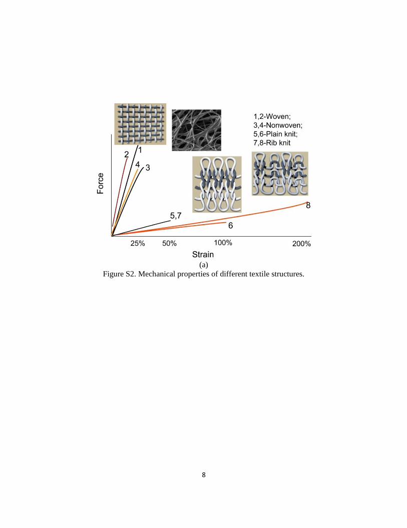
Textile fabrics, including woven, knitting and nonwoven, are thin (~<1mm), lightweight (~grams
per square meter), soft (Young’s modulus: <1MPa), drapable in three dimensions, as well as
porous (or breathable), are attractive to be used as flexible substrates or circuit boards for
wearable electronics on human bodies. As illustrated in Fig.S2, a plain woven fabric is produced
by interlacing warp (along the length) and weft yarns (along the width of the fabric) at right
angles to each other; a nonwoven fabric is made from long fibers, bonded together by chemical,
mechanical, heat treatment. Unlike woven and nonwoven textiles, knitted fabric is formed by
interlacing yarn in a series of connected loops, where the column and row directions of the loop
are referred to as wale and course, respectively. Thus, the knitted fabric, especially weft knitting,
in comparison to woven and nonwoven textiles, is much more elastic (usually beyond 100%
strain) owing to its three-dimensional loop configuration. Hence, the efforts to develop knitted
FCBs may open doors to new applications in areas where woven and nonwoven electronic
devices are not effective, such as intimately wearable electronics or next-to-skin health
monitoring network or system.
2
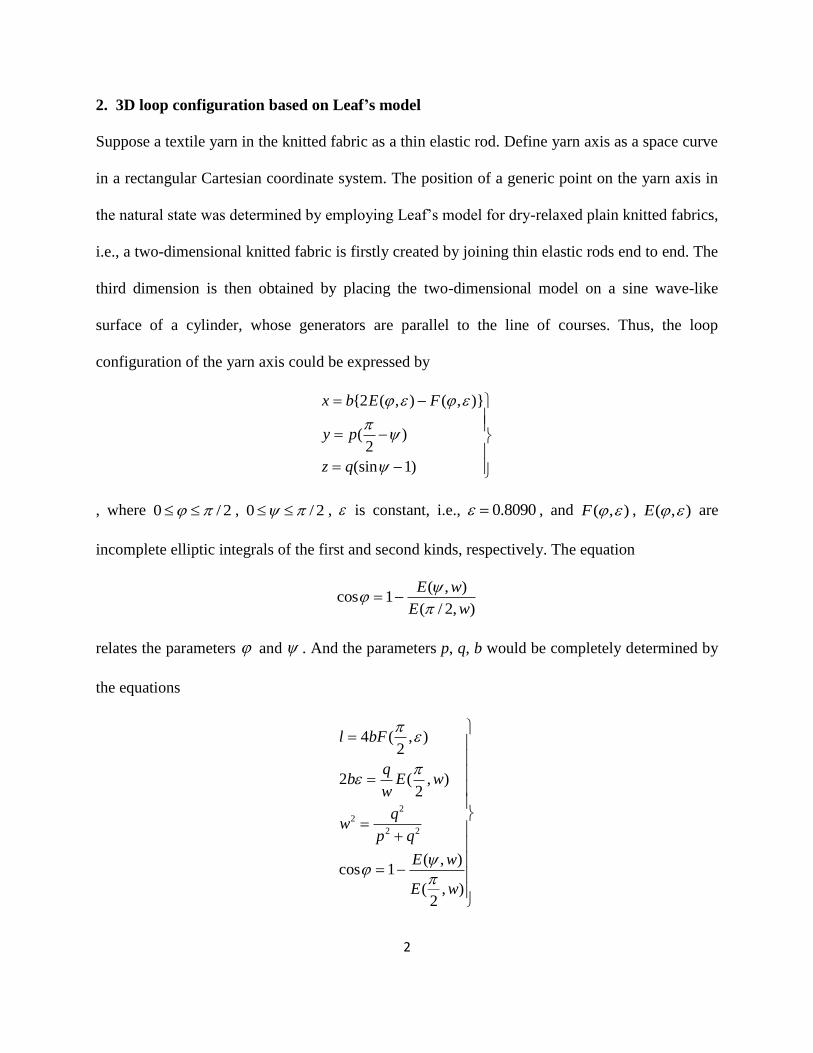
2. 3D loop configuration based on Leaf’s model
Suppose a textile yarn in the knitted fabric as a thin elastic rod. Define yarn axis as a space curve
in a rectangular Cartesian coordinate system. The position of a generic point on the yarn axis in
the natural state was determined by employing Leaf’s model for dry-relaxed plain knitted fabrics,
i.e., a two-dimensional knitted fabric is firstly created by joining thin elastic rods end to end. The
third dimension is then obtained by placing the two-dimensional model on a sine wave-like
surface of a cylinder, whose generators are parallel to the line of courses. Thus, the loop
configuration of the yarn axis could be expressed by
{2 ( , ) ( , )}
( )2
(sin 1)
x b E F
y p
z q
, where 0 / 2 , 0 / 2 , is constant, i.e., 0.8090 , and ( , )F , ( , )E are
incomplete elliptic integrals of the first and second kinds, respectively. The equation
( , )cos 1
( / 2, )
E w
E w
relates the parameters and . And the parameters p, q, b would be completely determined by
the equations
22
2 2
4 ( , )2
2 ( , )2
( , )cos 1
( , )2
l bF
qb E w
w
qw
p q
E w
E w
3
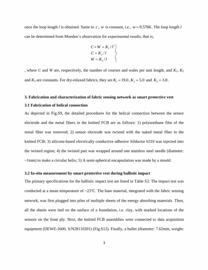
once the loop length l is obtained. Same to , w is constant, i.e., 0.5766w . The loop length l
can be determined from Munden’s observation for experimental results, that is,
2
1
2
3
/
/
/
C W K l
C K l
W K l
, where C and W are, respectively, the number of courses and wales per unit length, and K1, K2
and K3 are constants. For dry-relaxed fabrics, they are 1 19.0K , 2 5.0K and 3 3.8K .
3. Fabrication and characterization of fabric sensing network as smart protective vest
3.1 Fabrication of helical connection
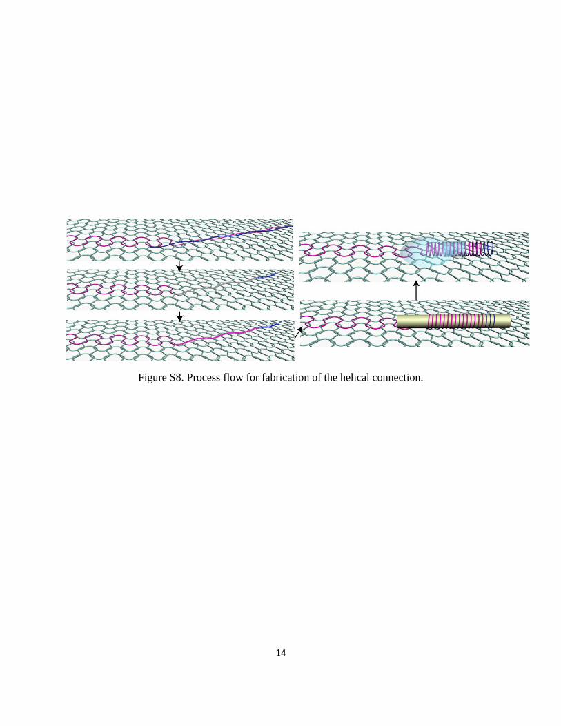
As depicted in Fig.S9, the detailed procedures for the helical connection between the sensor
electrode and the metal fibers in the knitted FCB are as follows: 1) polyurethane film of the
metal fiber was removed; 2) sensor electrode was twisted with the naked metal fiber in the
knitted FCB; 3) silicone-based electrically conductive adhesive Silductor 6310 was injected into
the twisted region; 4) the twisted part was wrapped around one stainless steel needle (diameter:
~1mm) to make a circular helix; 5) A semi-spherical encapsulation was made by a mould.
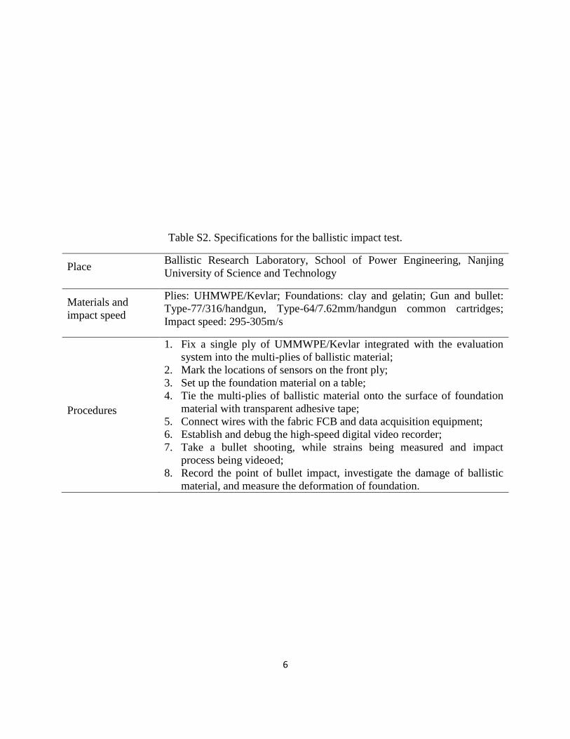
3.2 In-situ measurement by smart protective vest during ballistic impact
The primary specifications for the ballistic impact test are listed in Table S2. The impact test was
conducted at a mean temperature of ~23℃ . The base material, integrated with the fabric sensing
network, was first plugged into piles of multiple sheets of the energy absorbing materials. Then,
all the sheets were tied on the surface of a foundation, i.e. clay, with marked locations of the
sensors on the front ply. Next, the knitted FCB assemblies were connected to data acquisition
equipment (DEWE-2600, S/N28110201) (Fig.S12). Finally, a bullet (diameter: 7.62mm, weight:

4
~4.7g) was impacted at the centre of the sensor array on the energy absorbing material pile and
made an indentation into the foundation clay. The impact velocity was 295-305m.s-1
. In the
impact process, the electrical resistance of the sensors was recorded by the data acquisition
equipment with a sampling rate of 100 kHz.
5
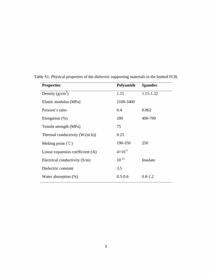
Table S1. Physical properties of the dielectric supporting materials in the knitted FCB.
Properties Polyamide Spandex
Density (g/cm3) 1.15 1.15-1.32
Elastic modulus (MPa) 2100-3400
Poisson’s ratio 0.4 0.862
Elongation (%) 200 400-700
Tensile strength (MPa) 75
Thermal conductivity (W/(m.k)) 0.25
Melting point (℃) 190-350 250
Linear expansion coefficient (/k) 4×10⁻⁵
Electrical conductivity (S/m) 10-12
Insulate
Dielectric constant 3.5
Water absorption (%) 0.5-0.6 0.8-1.2
6
Table S2. Specifications for the ballistic impact test.
Place Ballistic Research Laboratory, School of Power Engineering, Nanjing
University of Science and Technology
Materials and
impact speed
Plies: UHMWPE/Kevlar; Foundations: clay and gelatin; Gun and bullet:
Type-77/316/handgun, Type-64/7.62mm/handgun common cartridges;
Impact speed: 295-305m/s
Procedures
1. Fix a single ply of UMMWPE/Kevlar integrated with the evaluation
system into the multi-plies of ballistic material;
2. Mark the locations of sensors on the front ply;
3. Set up the foundation material on a table;
4. Tie the multi-plies of ballistic material onto the surface of foundation
material with transparent adhesive tape;
5. Connect wires with the fabric FCB and data acquisition equipment;
6. Establish and debug the high-speed digital video recorder;
7. Take a bullet shooting, while strains being measured and impact
process being videoed;
8. Record the point of bullet impact, investigate the damage of ballistic
material, and measure the deformation of foundation.
7
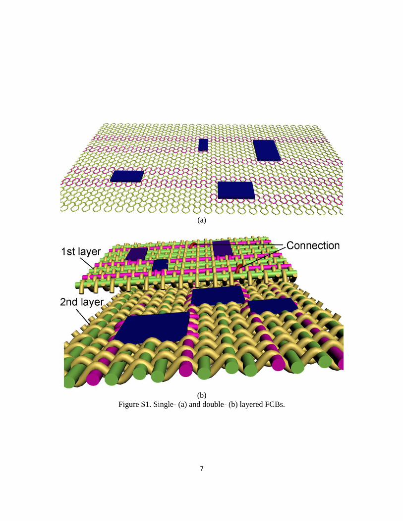
(a)
(b)
Figure S1. Single- (a) and double- (b) layered FCBs.
8
(a)
Figure S2. Mechanical properties of different textile structures.
9
0 4 8 12 16 20 24
0
3
6
9
12
15
0.02mm
0.03mm
0.05mm
0.08mm
Strain (%)
(R-R
0)/
R0*1
00 (
%)
0.0
0.3
0.6
0.9
1.2
1.5
1.8F
orc
e (N
)
(a) (b)
(c)
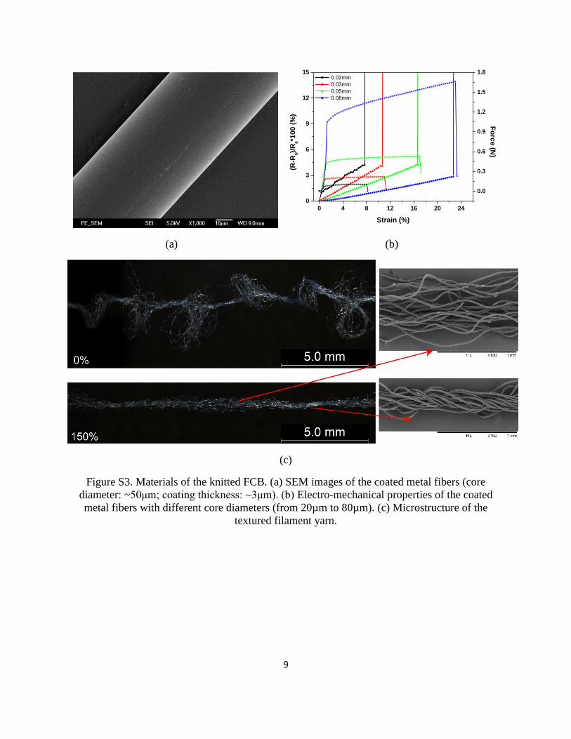
Figure S3. Materials of the knitted FCB. (a) SEM images of the coated metal fibers (core
diameter: ~50μm; coating thickness: ~3μm). (b) Electro-mechanical properties of the coated
metal fibers with different core diameters (from 20µm to 80µm). (c) Microstructure of the
textured filament yarn.
10
(a) (b)
0 100 200 300 400 500 600
0
50
100
150
200
250
300
Vertical
Horizontal
3D punching
Fo
rce (
N)
Strain (%)
(c) (d)
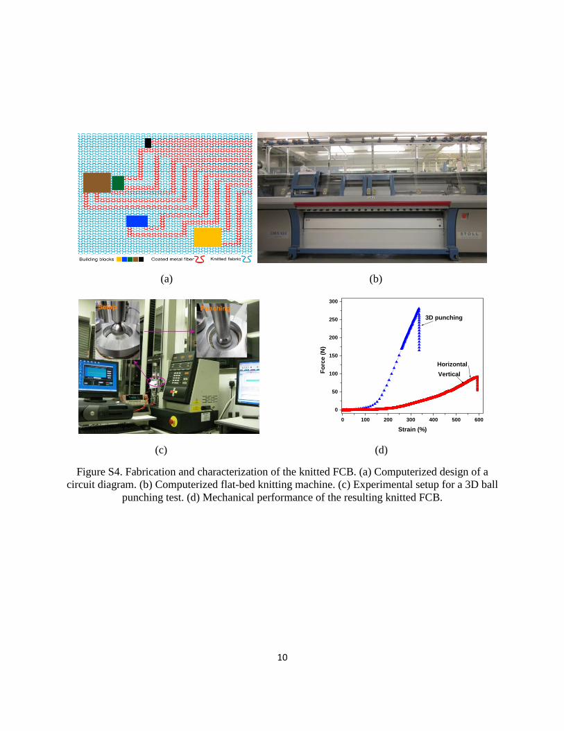
Figure S4. Fabrication and characterization of the knitted FCB. (a) Computerized design of a
circuit diagram. (b) Computerized flat-bed knitting machine. (c) Experimental setup for a 3D ball
punching test. (d) Mechanical performance of the resulting knitted FCB.
11
(a) (b)
(c)
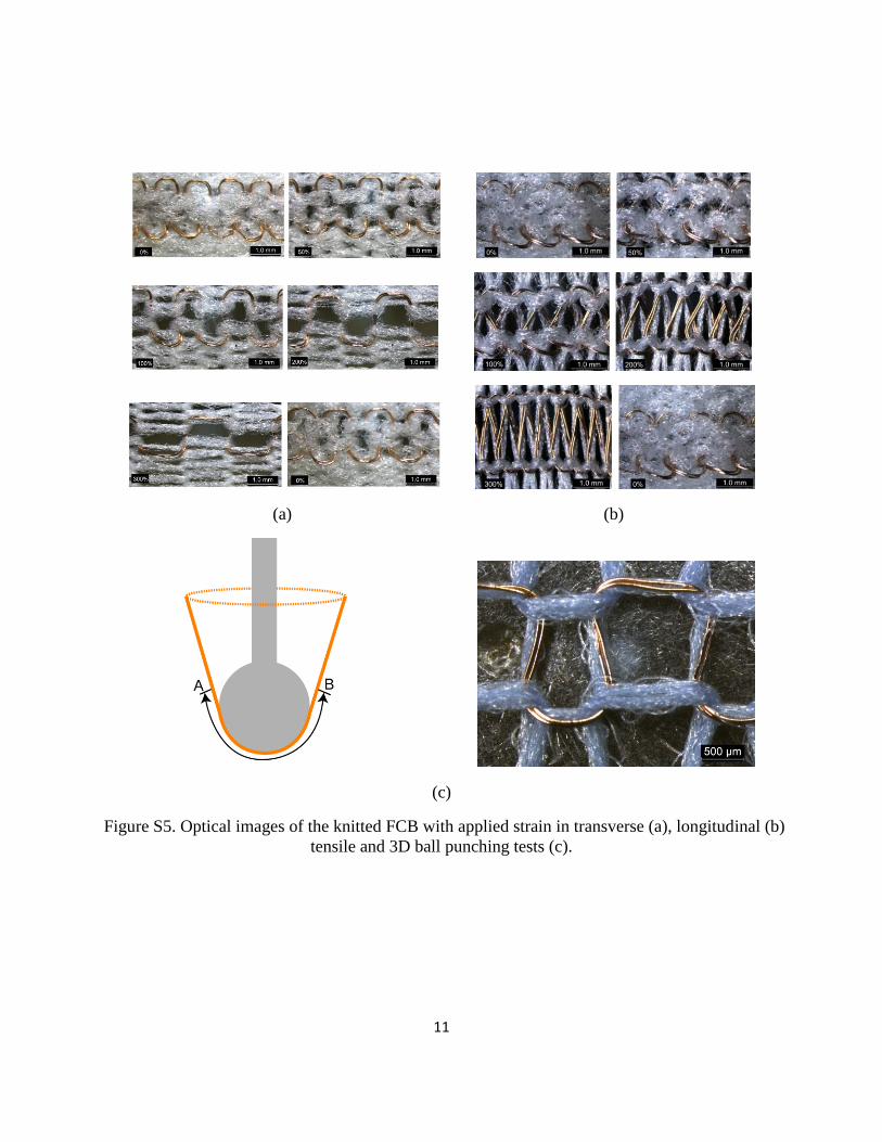
Figure S5. Optical images of the knitted FCB with applied strain in transverse (a), longitudinal (b)
tensile and 3D ball punching tests (c).
12
(a) (b)
(c) (d)
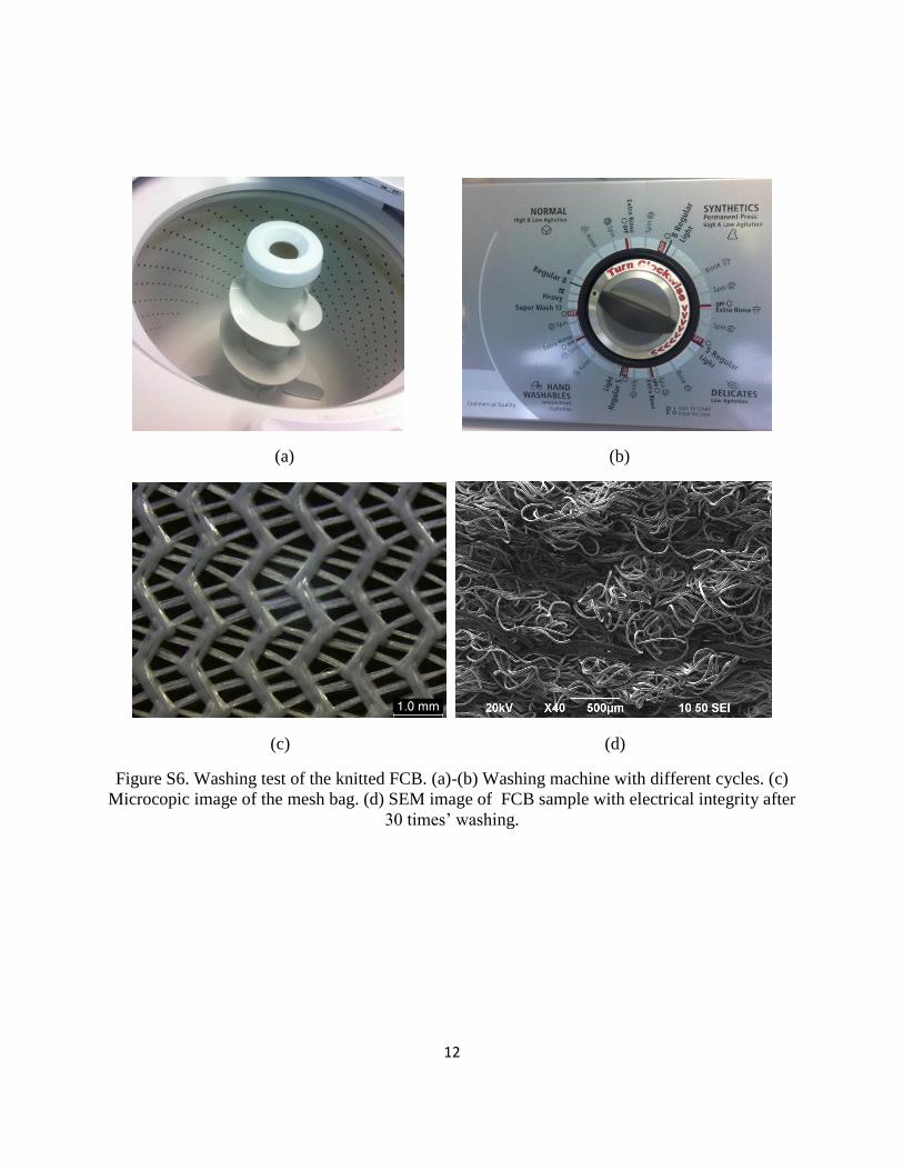
Figure S6. Washing test of the knitted FCB. (a)-(b) Washing machine with different cycles. (c)
Microcopic image of the mesh bag. (d) SEM image of FCB sample with electrical integrity after
30 times’ washing.
13
(a) (b) (c) (d)
(e)
(f)
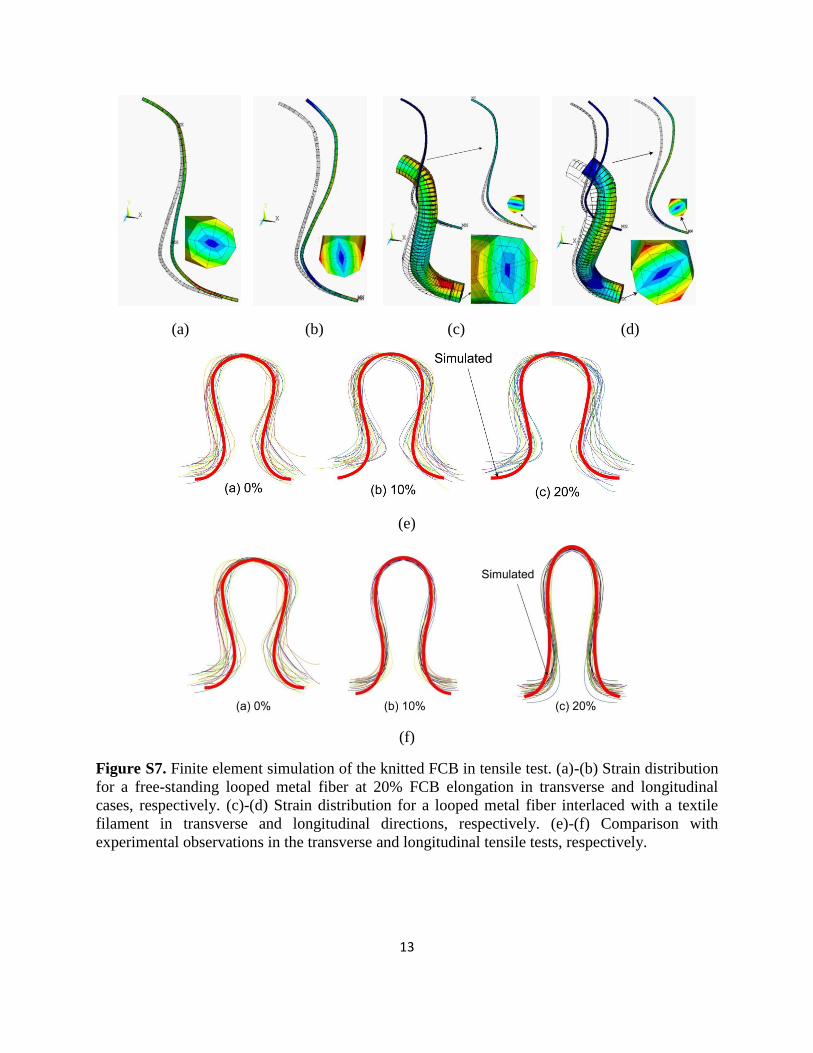
Figure S7. Finite element simulation of the knitted FCB in tensile test. (a)-(b) Strain distribution
for a free-standing looped metal fiber at 20% FCB elongation in transverse and longitudinal
cases, respectively. (c)-(d) Strain distribution for a looped metal fiber interlaced with a textile
filament in transverse and longitudinal directions, respectively. (e)-(f) Comparison with
experimental observations in the transverse and longitudinal tensile tests, respectively.
14
Figure S8. Process flow for fabrication of the helical connection.
15
(a)
(b) (c)
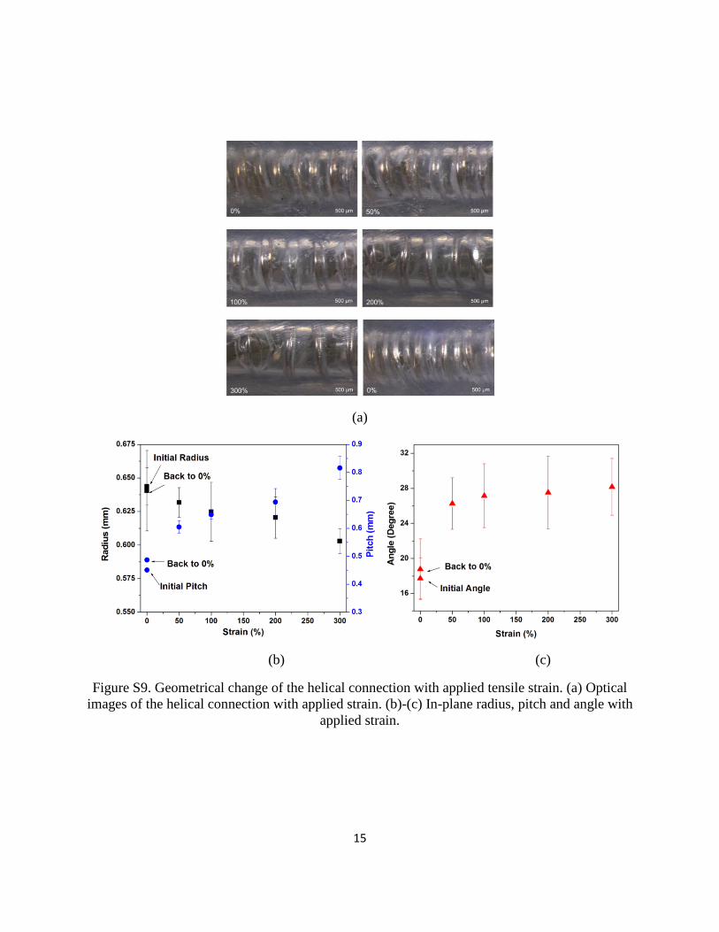
Figure S9. Geometrical change of the helical connection with applied tensile strain. (a) Optical
images of the helical connection with applied strain. (b)-(c) In-plane radius, pitch and angle with
applied strain.
16
0 10 20 30 40 50 60 70
0
50
100
150
200
250
300
350
After fabrication
Before fabrication
(R-R
0)/
R0*1
00
(%)
Strain (%)
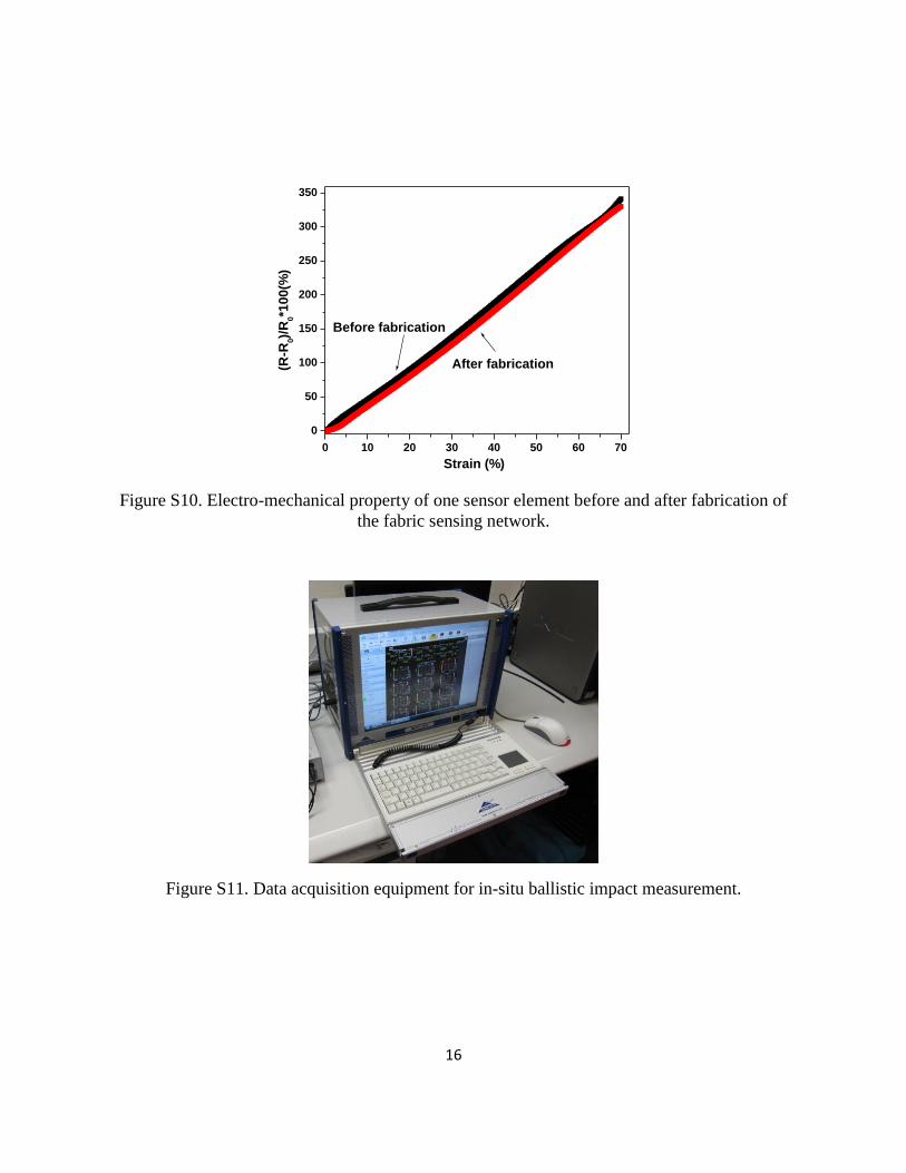
Figure S10. Electro-mechanical property of one sensor element before and after fabrication of
the fabric sensing network.
Figure S11. Data acquisition equipment for in-situ ballistic impact measurement.