Embed Size (px)
Citation preview
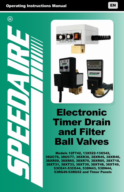
Operating Instructions Manual EN
Electronic Timer Drain and Filter
Ball ValvesModels 12F742, 13X522-13X542,
38UC76, 38UC77, 38XR36, 38XR45, 38XR46, 38XR59, 38XR65, 38XR70, 38XR85, 38XT18, 38XT31, 38XT33, 38XT39, 38XT48, 38XT49,
53CE41-53CE44, 53DN43, 53DN44, 53RG49-53RG52 and Timer Panels
PLEASE READ AND SAVE THESE INSTRUCTIONS.
READ CAREFULLY BEFORE ATTEMPTING
TO ASSEMBLE, INSTALL, OPERATE OR MAINTAIN THE
PRODUCT DESCRIBED.
PROTECT YOURSELF AND OTHERS BY OBSERVING ALL
SAFETY INFORMATION. FAILURE TO COMPLY WITH INSTRUCTIONS
COULD RESULT IN PERSONAL INJURY AND/OR PROPERTY
DAMAGE! RETAIN INSTRUCTIONS FOR FUTURE REFERENCE.
PLEASE REFER TO BACK COVER FOR INFORMATION REGARDING
SPEEDAIRE’S WARRANTY AND OTHER IMPORTANT INFORMATION.
Model #: ___________________
Serial #: ___________________
Purch. Date: _______________
Form 5SXXXX / Printed in XXXXXXXXX Version XX XX/XXXX
© 2017 Dayton Electric Manufacturing Co.All Rights Reserved
1
Assem
bly /
InstA
llAtIon
oper
AtIon
tro
ub
lesho
otIn
gm
AIn
tenA
nc
e / r
epAIr
DEsCRIPTIONSpeedaire Electronic Timer Drain Valves remove condensed water and oil from the air receiver tank. Additional drains may be installed throughout your compressed air system, including aftercoolers, filters, drip legs and dryers. The Condensate Drain Valve operates on a timer which can be set to automatically drain at operator determined intervals.
UNPaCkING
Inspect:
• RemovetheCondensateDrainValvefrompackagingandinspect for transportation damage. Ensure the voltage rating on the solenoid valve matches your power supply.
• see general safety Instructions on page 2, and cautions and Warnings as shown.
gettIn
g stA
rted
sAfety /
specIfIc
AtIon
s
mA
Inte
nA
nc
e /
rep
AIr
tro
ub
lesh
oo
tIn
go
per
AtIo
nA
ssem
bly
/ In
stA
llAt
Ion
get
tIn
g s
tAr
ted
2
sAfe
ty /
spec
IfIc
AtIo
ns
GENERal saFETy INsTRUCTIONsTo ensure safe and enduring performance of this product, you must comply with the instructions enclosed herein. Non-compliance with instructions or improper handling of the product will void your warranty. This product is designed to drain condensate from compressed air systems. Usage of this product in conditions not specified in this manual or contrary to the instructions hereby provided is considered improper. The manufacturer will not be held liable for any damages resulting from improper use of the product.
attention:
• Observevalidandgenerallyacceptedsafetyruleswhenplanning,installing and using this product.
• Takepropermeasurestopreventunintentionaloperationofthe product or damage to it.
• Donotattempttodisassemblethisproductorlinesinthesystem while they are under pressure.
• Alwaysdepressurizethecompressedairsystembeforeworking on the system.
• Installationandmaintenanceworkshouldbecarriedoutinaccordancewith the relevant local regulations and codes of practice and only by suitably qualified personnel.
Itisimportantthatpersonnelusesafeworkingpracticesandobserveallregulations and legal requirements for safety when operating this product. When handling, operating or carrying out maintenance on this product, personnel must employ safe engineering practices and observe all local healthandsafetyrequirementsandregulations.Internationalusersreferto regulations that prevail within the country of installation. Most accidents which occur during the operation and maintenance of machinery are the result of failure to observe basic safety rules or pre-cautions. An accident canoftenbeavoidedbyrecognizingasituationthatispotentiallydangerous.Improperoperationormaintenanceofthisproductcouldbedangerousand result in an accident causing injury or death. The manufacturer cannot anticipate every possible circumstance, which may represent a potential hazard.TheWARNINGSinthismanualcoverthemostcommonpotentialhazardsandarethereforenotall-inclusive.Iftheuseremploysanoperatingprocedure, an item of equipment or a method of working which is not specifically recommended by the manufacturer, they must ensure that the product will not be damaged or made unsafe and that there is no risk to persons or property. The specifications outlined in this document are accurate at time of publication but may change without prior notice.
Disconnect or depressurize compressed air line (system) prior to any installation or maintenance
activity. Eye Protection goggles or safety glasses are always recommended during installation and maintenance.
3
gettIn
g stA
rted
oper
AtIon
tro
ub
lesho
otIn
gm
AIn
tenA
nc
e / r
epAIr
Assem
bly /
InstA
llAtIon
sAfety /
specIfIc
AtIon
s
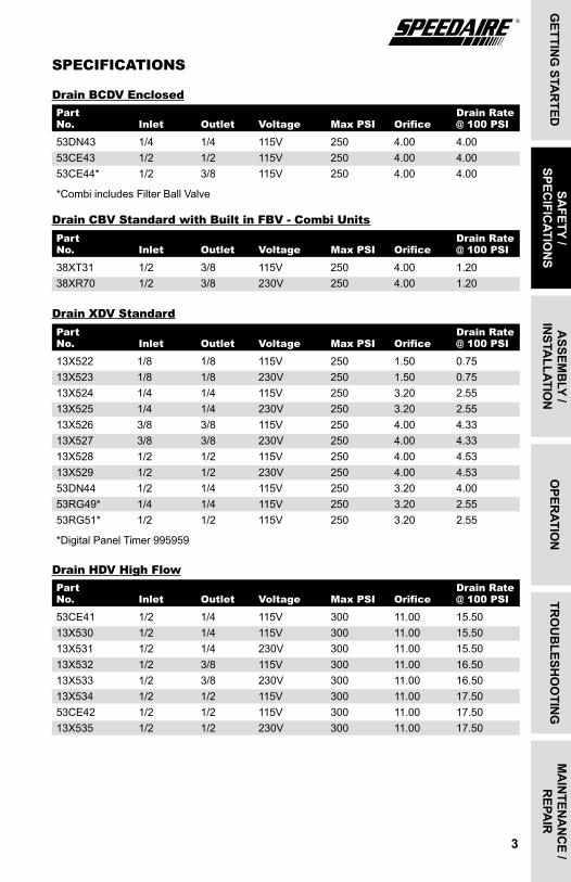
53DN43 1/4 1/4 115V 250 4.00 4.00 53CE43 1/2 1/2 115V 250 4.00 4.00 53CE44* 1/2 3/8 115V 250 4.00 4.00
*Combi includes Filter Ball Valve
Part Drain Rate No. Inlet Outlet Voltage Max PsI Orifice @ 100 PsI
sPECIFICaTIONs
Drain BCDV Enclosed
38XT31 1/2 3/8 115V 250 4.00 1.2038XR70 1/2 3/8 230V 250 4.00 1.20
Part Drain Rate No. Inlet Outlet Voltage Max PsI Orifice @ 100 PsI
Drain CBV standard with Built in FBV - Combi Units
Part Drain Rate No. Inlet Outlet Voltage Max PsI Orifice @ 100 PsI
Drain XDV standard
13X522 1/8 1/8 115V 250 1.50 0.7513X523 1/8 1/8 230V 250 1.50 0.75 13X524 1/4 1/4 115V 250 3.20 2.55 13X525 1/4 1/4 230V 250 3.20 2.55 13X526 3/8 3/8 115V 250 4.00 4.3313X527 3/8 3/8 230V 250 4.00 4.33 13X528 1/2 1/2 115V 250 4.00 4.53 13X529 1/2 1/2 230V 250 4.00 4.53 53DN44 1/2 1/4 115V 250 3.20 4.0053RG49* 1/4 1/4 115V 250 3.20 2.5553RG51* 1/2 1/2 115V 250 3.20 2.55
*Digital Panel Timer 995959
53CE41 1/2 1/4 115V 300 11.00 15.50 13X530 1/2 1/4 115V 300 11.00 15.50 13X531 1/2 1/4 230V 300 11.00 15.50 13X532 1/2 3/8 115V 300 11.00 16.50 13X533 1/2 3/8 230V 300 11.00 16.5013X534 1/2 1/2 115V 300 11.00 17.5053CE42 1/2 1/2 115V 300 11.00 17.5013X535 1/2 1/2 230V 300 11.00 17.50
Part Drain Rate No. Inlet Outlet Voltage Max PsI Orifice @ 100 PsI
Drain HDV High Flow
mA
Inte
nA
nc
e /
rep
AIr
tro
ub
lesh
oo
tIn
go
per
AtIo
ng
ettI
ng
stA
rte
d
4
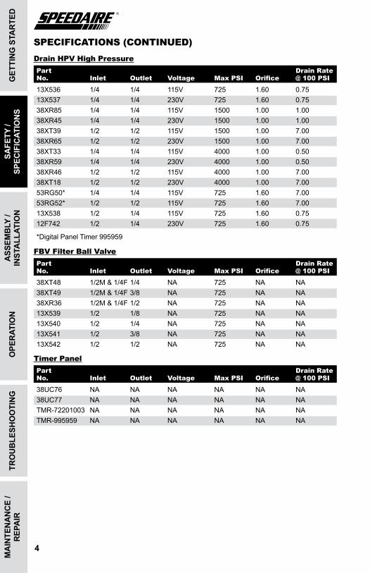
sPECIFICaTIONs (CONTINUED)
Ass
emb
ly /
Inst
All
AtIo
nsA
fety
/ sp
ecIf
IcAt
Ion
s
Part Drain Rate No. Inlet Outlet Voltage Max PsI Orifice @ 100 PsI
Drain HPV High Pressure
13X536 1/4 1/4 115V 725 1.60 0.7513X537 1/4 1/4 230V 725 1.60 0.7538XR85 1/4 1/4 115V 1500 1.00 1.0038XR45 1/4 1/4 230V 1500 1.00 1.0038XT39 1/2 1/2 115V 1500 1.00 7.0038XR65 1/2 1/2 230V 1500 1.00 7.00 38XT33 1/4 1/4 115V 4000 1.00 0.5038XR59 1/4 1/4 230V 4000 1.00 0.5038XR46 1/2 1/2 115V 4000 1.00 7.0038XT18 1/2 1/2 230V 4000 1.00 7.0053RG50* 1/4 1/4 115V 725 1.60 7.0053RG52* 1/2 1/2 115V 725 1.60 7.0013X538 1/2 1/4 115V 725 1.60 0.7512F742 1/2 1/4 230V 725 1.60 0.75
*Digital Panel Timer 995959
Part Drain Rate No. Inlet Outlet Voltage Max PsI Orifice @ 100 PsI
FBV Filter Ball Valve
38XT48 1/2M&1/4F1/4 NA 725 NA NA38XT49 1/2M&1/4F3/8 NA 725 NA NA38XR36 1/2M&1/4F1/2 NA 725 NA NA13X539 1/2 1/8 NA 725 NA NA13X540 1/2 1/4 NA 725 NA NA13X541 1/2 3/8 NA 725 NA NA13X542 1/2 1/2 NA 725 NA NA
Part Drain Rate No. Inlet Outlet Voltage Max PsI Orifice @ 100 PsI
Timer Panel
38UC76 NA NA NA NA NA NA38UC77 NA NA NA NA NA NATMR-72201003 NA NA NA NA NA NATMR-995959 NA NA NA NA NA NA
5
gettIn
g stA
rted
oper
AtIon
tro
ub
lesho
otIn
gm
AIn
tenA
nc
e / r
epAIr
Assem
bly /
InstA
llAtIon
sAfety /
specIfIc
AtIon
s
INsTallaTION INsTRUCTIONsCompressors that have been in service without an automatic drain should be cleaned of all debris before installation of the new drain.
DO NOT install the Condensate Drain Valve on a pressurized tank. Depressurize the tank and
disconnect the power supply before installing.
NOTE: For ease of installation, it may be necessary to elevate the tank. Ensure adequate lifting equipment is available.
1. InstalltheCondensateDrainValveusingpropersealantonthethreads.Ensure the sealant does not enter the valve body.
2. Supply the Condensate Drain Valve with proper electrical supply voltage.
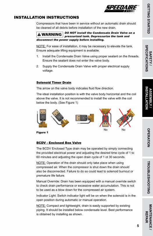
solenoid Timer Drain
The arrow on the valve body indicates fluid flow direction.
Theidealinstallationpositioniswiththevalvebodyhorizontalandthecoilabovethevalve.Itisnotrecommendedtoinstallthevalvewiththecoilbelow the body. (See Figure 1)
Figure 1
BCDV - Enclosed Box Valve
The BCDV Enclosed Type drain may be operated by simply connecting the provided electrical power and adjusting the desired time cycle of 1 to 60 minutes and adjusting the open drain cycle of 1 ot 30 seconds.
NOTE: Operationofthedrainshouldonlytakeplacewhenusingcompressed air. When the compressor is shut down the drain should also be disconnected. Failure to do so could lead to solenoid burnout or premature life failure.
ManualOverride:Drainhasbeenequippedwithamanualoverrideswitchto check drain performance or excessive water accumulation. This is not to be used as a blow down for the compressed air system.
IndicatorLight:Switchindicatorlightwillbeonwhenthesolenoidisintheopen position during automatic or manual operation.
NOTE: Compact and lightweight, drain is easily supported by existing piping.Itshouldbeinstalledbelowcondensatelevel.Bestperformance is obtained by installing as shown.
No No
mA
Inte
nA
nc
e /
rep
AIr
tro
ub
lesh
oo
tIn
go
per
AtIo
nsA
fety
/ sp
ecIf
IcAt
Ion
sg
ettI
ng
stA
rte
d
6
Ass
emb
ly /
Inst
All
AtIo
n
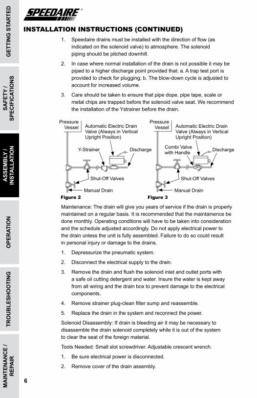
INsTallaTION INsTRUCTIONs (CONTINUED)1. Speedaire drains must be installed with the direction of flow (as
indicated on the solenoid valve) to atmosphere. The solenoid piping should be pitched downhill.
2. Incasewherenormalinstallationofthedrainisnotpossibleitmaybepipedtoahigherdischargepointprovidedthat:a.Atraptestportisprovided to check for plugging; b. The blow-down cycle is adjusted to account for increased volume.
3. Care should be taken to ensure that pipe dope, pipe tape, scale or metal chips are trapped before the solenoid valve seat. We recommend the installation of the Ystrainer before the drain.
Maintenance:Thedrainwillgiveyouyearsofserviceifthedrainisproperlymaintainedonaregularbasis.Itisrecommendedthatthemaintainencebedonemonthly.Operatingconditionswillhavetobetakenintoconsiderationand the schedule adjusted accordingly. Do not apply electrical power to the drain unless the unit is fully assembled. Failure to do so could result in personal injury or damage to the drains.
1. Depressurizethepneumaticsystem.
2. Disconnect the electrical supply to the drain.
3. Removethedrainandflushthesolenoidinletandoutletportswithasafeoilcuttingdetergentandwater.Insurethewateriskeptawayfrom all wiring and the drain box to prevent damage to the electrical components.
4. Removestrainerplug-cleanfiltersumpandreassemble.
5. Replacethedraininthesystemandreconnectthepower.
SolenoidDisassembly:Ifdrainisbleedingairitmaybenecessarytodisassemble the drain solenoid completely while it is out of the system to clear the seat of the foreign material.
ToolsNeeded:Smallslotscrewdriver.Adjustablecrescentwrench.
1. Be sure electrical power is disconnected.
2. Removecoverofthedrainassembly.
Figure 2 Figure 3
Pressure VesselAutomatic Electric Drain
Valve (Always in Vertical Upright Position)
DischargeY-Strainer
Shut-OffValves
Manual Drain
Pressure Vessel Automatic Electric Drain
Valve (Always in Vertical Upright Position)
DischargeCombi Valve with Handle
Shut-OffValves
Manual Drain
7
gettIn
g stA
rted
sAfety /
specIfIc
AtIon
str
ou
blesh
oo
tIng
mA
Inten
An
ce /
repA
IrA
ssemb
ly / In
stAllAtIo
no
perAtIo
n
INsTallaTION INsTRUCTIONs (CONTINUED)3. Removenutwhichretainssolenoidtocoilandremovesolenoidvalve.
Observethedirectionofflowindicatoronthesolenoidsothatitcan be reassembled in the same direction.
4. Removethestemassemble.Carefullyunthreadthestemassemblyof the solenoid (CCW). Do not strike or twist the stem with any object. Doing so may damage the assembly.
5. Inspectvalveseatandremoveanyforeignmaterial.
6. Inspectplungerassemblyandremoveanyforeignmaterial.IFITISNECESSARYTOUSEASOLVENT,ITMAYBEUSEDONLYONMETALSURFACES.
7. Reassemblethesolenoidandvalvereversingtheaboveprocedures.Be sure that the actuator cover is carefully aligned over the pin and the additional outer cast portion is positioned on the outlet side of the solenoid.
8. Reinstallsolenoidintothehousing,besuretheinletandoutletarepositioned correctly for the flow.
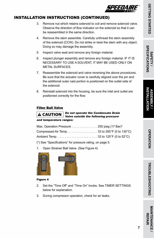
Filter Ball ValveDo not operate the Condensate Drain Valve outside the following pressure
and temperature ranges:
Max.OperationPressure . . . . . . . . . . . . . . . 250psig(17Bar)*Compressed Air Temp. . . . . . . . . . . . . . . . . . 33 to 265°F (0 to 130°C)Ambient Temp. . . . . . . . . . . . . . . . . . . . . . . . 33 to 125°F (0 to 52°C)
(*) See “Specifications” for pressure rating, on page 5.
1. OpenStrainerBallValve.(SeeFigure4)
Figure 4
2. Setthe“TimeOff”and“TimeOn”knobs.SeeTIMERSETTINGS below for explanation.
3. During compressor operation, check for air leaks.
mA
Inte
nA
nc
e /
rep
AIr
sAfe
ty /
spec
IfIc
AtIo
ns
get
tIn
g s
tAr
ted
8
tro
ub
lesh
oo
tIn
gA
ssem
bly
/ In
stA
llAt
Ion
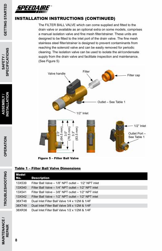
13X539 Filter Ball Valve – 1/8” NPT outlet – 1/2“ NPT inlet 13X540 Filter Ball Valve – 1/4” NPT outlet – 1/2“ NPT inlet 13X541 Filter Ball Valve – 3/8” NPT outlet – 1/2“ NPT inlet 13X542 Filter Ball Valve – 1/2” NPT outlet – 1/2“ NPT inlet38XT48 DualInletFilterBallValve1/4x1/2M&1/4F38XT49 DualInletFilterBallValve3/8x1/2M&1/4F38XR36 DualInletFilterBallValve1/2x1/2M&1/4F
Model No. Description
Table 1 – Filter Ball Valve Dimensions
Valve handleFilter
Filter cap
Outlet–SeeTable1
1/2”Inlet
1/2”Inlet
OutletPort– See Table 1
Figure 5 – Filter Ball Valve
2.5”
(6
4.5
mm
)3.
0”
(76.5mm)
3.3”
(8
3.5
mm
)
INsTallaTION INsTRUCTIONs (CONTINUED)TheFILTERBALLVALVEwhichcancomesuppliedandfittedtothedrain valve or available as an optional extra on some models, comprises a manual isolation valve and fine mesh filter/strainer. These units are designed to be fitted to the inlet port of the drain valve. The fine mesh stainless steel filter/strainer is designed to prevent contaminants from reaching the solenoid valve and can be easily removed for periodic cleaning. The isolation valve can be used to isolate the air/condensate supply from the drain valve and facilitate inspection and maintenance. (See Figure 5)
ope
rAt
Ion
9
gettIn
g stA
rted
sAfety /
specIfIc
AtIon
sA
ssemb
ly / In
stAllAtIo
ntr
ou
blesh
oo
tIng
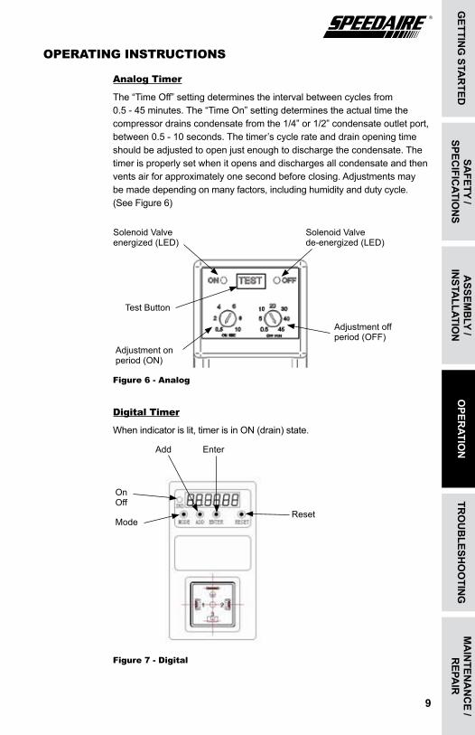
OPERaTING INsTRUCTIONs
analog Timer
The“TimeOff”settingdeterminestheintervalbetweencyclesfrom 0.5-45minutes.The“TimeOn”settingdeterminestheactualtimethecompressor drains condensate from the 1/4” or 1/2” condensate outlet port, between 0.5 - 10 seconds. The timer’s cycle rate and drain opening time should be adjusted to open just enough to discharge the condensate. The timer is properly set when it opens and discharges all condensate and then vents air for approximately one second before closing. Adjustments may be made depending on many factors, including humidity and duty cycle. (See Figure 6)
Figure 6 - analog
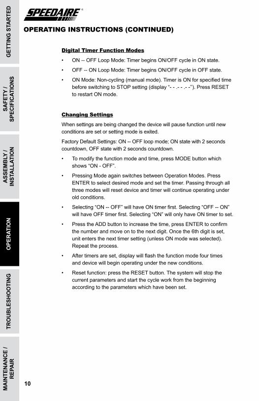
Digital Timer
Whenindicatorislit,timerisinON(drain)state.
Figure 7 - Digital
Solenoid Valve energized(LED)
Solenoid Valve de-energized(LED)
Test Button
Adjustment on period(ON)
Adjustment off period(OFF)
mA
Inten
An
ce /
repA
Iro
perAtIo
nAdd
OnOff
Mode
Enter
Reset
OPERaTING INsTRUCTIONs (CONTINUED)
Digital Timer Function Modes
• ON--OFFLoopMode:TimerbeginsON/OFFcycleinONstate.
• OFF--ONLoopMode:TimerbeginsON/OFFcycleinOFFstate.
• ONMode:Non-cycling(manualmode).TimerisONforspecifiedtimebeforeswitchingtoSTOPsetting(display“--.--.--’’).PressRESET torestartONmode.
Changing settings
When settings are being changed the device will pause function until new conditions are set or setting mode is exited.
FactoryDefaultSettings:ON--OFFloopmode;ONstatewith2secondscountdown,OFFstatewith2secondscountdown.
• Tomodifythefunctionmodeandtime,pressMODEbuttonwhichshows“ON-OFF”.
• PressingModeagainswitchesbetweenOperationModes.PressENTERtoselectdesiredmodeandsetthetimer.Passingthroughallthree modes will reset device and timer will continue operating under old conditions.
• Selecting“ON--OFF”willhaveONtimerfirst.Selecting“OFF--ON”willhaveOFFtimerfirst.Selecting“ON”willonlyhaveONtimertoset.
• PresstheADDbuttontoincreasethetime,pressENTERtoconfirmthenumberandmoveontothenextdigit.Oncethe6thdigitisset, unitentersthenexttimersetting(unlessONmodewasselected).Repeattheprocess.
• Aftertimersareset,displaywillflashthefunctionmodefourtimes and device will begin operating under the new conditions.
• Resetfunction:presstheRESETbutton.Thesystemwillstopthecurrent parameters and start the cycle work from the beginning according to the parameters which have been set.
mA
Inte
nA
nc
e /
rep
AIr
tro
ub
lesh
oo
tIn
gA
ssem
bly
/ In
stA
llAt
Ion
sAfe
ty /
spec
IfIc
AtIo
ns
get
tIn
g s
tAr
ted
10
ope
rAt
Ion
11
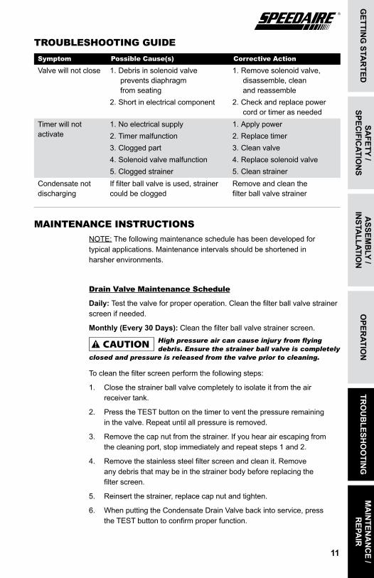
TROUBlEsHOOTING GUIDEsymptom Possible Cause(s) Corrective action
Valve will not close 1. Debris in solenoid valve prevents diaphragm from seating
2. Short in electrical component
1.Removesolenoidvalve,disassemble, clean and reassemble
2. Check and replace power cord or timer as needed
Timer will not activate
1. No electrical supply2. Timer malfunction3. Clogged part4. Solenoid valve malfunction5. Clogged strainer
1. Apply power2.Replacetimer3. Clean valve4.Replacesolenoidvalve5. Clean strainer
Condensate not discharging
Iffilterballvalveisused,strainercould be clogged
Removeandcleanthe filter ball valve strainer
MaINTENaNCE INsTRUCTIONsNOTE: The following maintenance schedule has been developed for typical applications. Maintenance intervals should be shortened in harsher environments.
Drain Valve Maintenance schedule
daily: Test the valve for proper operation. Clean the filter ball valve strainer screen if needed.
monthly (every 30 days): Clean the filter ball valve strainer screen.High pressure air can cause injury from flying debris. Ensure the strainer ball valve is completely
closed and pressure is released from the valve prior to cleaning.
Tocleanthefilterscreenperformthefollowingsteps:
1. Close the strainer ball valve completely to isolate it from the air receiver tank.
2. Press the TEST button on the timer to vent the pressure remaining inthevalve.Repeatuntilallpressureisremoved.
3. Removethecapnutfromthestrainer.Ifyouhearairescapingfrom the cleaning port, stop immediately and repeat steps 1 and 2.
4. Removethestainlesssteelfilterscreenandcleanit.Remove any debris that may be in the strainer body before replacing the filter screen.
5. Reinsertthestrainer,replacecapnutandtighten.
6. When putting the Condensate Drain Valve back into service, press the TEST button to confirm proper function.
gettIn
g stA
rted
sAfety /
specIfIc
AtIon
sA
ssemb
ly / In
stAllAtIo
ntr
ou
blesh
oo
tIng
oper
AtIon
mA
Inten
An
ce /
repA
Ir
SPEEDAIRE ONE-YEAR LIMITED WARRANTYSPEEDAIRE ONE-YEAR LIMITED WARRANTY. All Speedaire® product models covered in this manual are warranted by Dayton Electric Mfg. Co. (“Dayton”) to the original user against defects in workmanship or materials under normal use for one year after date of purchase. If the Speedaire Product is part of a set, only the portion that is defective is subject to this warranty. Any product or part which is determined to be defective in material or workmanship and returned to an authorized service location, as Dayton or Dayton’s designee designates, shipping costs prepaid, will be, as the exclusive remedy, repaired or replaced with a new or reconditioned product or part of equal utility or a full refund given, at Dayton’s or Dayton’s designee’s option, at no charge. For limited warranty claim procedures, see “Warranty Service” below. This warranty is void if there is evidence of misuse, mis-repair, mis-installation, abuse or alteration. This warranty does not cover normal wear and tear of Speedaire Products or portions of them, or products or portions of them which are consumable in normal use. This limited warranty gives purchasers specific legal rights, and you may also have other rights which vary from jurisdiction to jurisdiction.
WARRANTY DISCLAIMERS AND LIMITATIONS OF LIABILITY RELATING TO ALL CUSTOMERS FOR ALL PRODUCTS
LIMITATION OF LIABILITY. TO THE EXTENT ALLOWABLE UNDER APPLICABLE LAW, DAYTON’S LIABILITY FOR CONSEQUENTIAL AND INCIDENTAL DAMAGES IS EXPRESSLY DISCLAIMED. DAYTON’S LIABILITY IN ALL EVENTS IS LIMITED TO AND SHALL NOT EXCEED THE PURCHASE PRICE PAID.
WARRANTY DISCLAIMER. A DILIGENT EFFORT HAS BEEN MADE TO PROVIDE PRODUCT INFORMATION AND ILLUSTRATE THE SPEEDAIRE PRODUCTS IN THIS LITERATURE ACCURATELY; HOWEVER, SUCH INFORMATION AND ILLUSTRATIONS ARE FOR THE SOLE PURPOSE OF IDENTIFICATION, AND DO NOT EXPRESS OR IMPLY A WARRANTY THAT THE SPEEDAIRE PRODUCTS ARE MERCHANTABLE, OR FIT FOR A PARTICULAR PURPOSE, OR THAT THE SPEEDAIRE PRODUCTS WILL NECESSARILY CONFORM TO THE ILLUSTRATIONS OR DESCRIPTIONS. EXCEPT AS PROVIDED BELOW, NO WARRANTY OR AFFIRMATION OF FACT, EXPRESSED OR IMPLIED, OTHER THAN AS STATED IN THE “LIMITED WARRANTY” ABOVE IS MADE OR AUTHORIZED BY DAYTON.
PRODUCT SUITABILITY. MANY JURISDICTIONS HAVE CODES AND REGULATIONS GOVERNING SALES, CONSTRUCTION, INSTALLATION, AND/OR USE OF PRODUCTS FOR CERTAIN PURPOSES, WHICH MAY VARY FROM THOSE IN NEIGHBORING AREAS. WHILE ATTEMPTS ARE MADE TO ASSURE THAT SPEEDAIRE PRODUCTS COMPLY WITH SUCH CODES, DAYTON CANNOT GUARANTEE COMPLIANCE, AND CANNOT BE RESPONSIBLE FOR HOW THE PRODUCT IS INSTALLED OR USED. BEFORE PURCHASE AND USE OF A PRODUCT, REVIEW THE SAFETY/SPECIFICATIONS, AND ALL APPLICABLE NATIONAL AND LOCAL CODES AND REGULATIONS, AND BE SURE THAT THE SPEEDAIRE PRODUCT, INSTALLATION, AND USE WILL COMPLY WITH THEM.
CONSUMERS ONLY. CERTAIN ASPECTS OF DISCLAIMERS ARE NOT APPLICABLE TO CONSUMER PRODUCTS SOLD TO CONSUMERS; (A) SOME JURISDICTIONS DO NOT ALLOW THE EXCLUSION OR LIMITATION OF INCIDENTAL OR CONSEQUENTIAL DAMAGES, SO THE ABOVE LIMITATION OR EXCLUSION MAY NOT APPLY TO YOU; (B) ALSO, SOME JURISDICTIONS DO NOT ALLOW A LIMITATION ON HOW LONG AN IMPLIED WARRANTY LASTS, SO THE ABOVE LIMITATION MAY NOT APPLY TO YOU; AND (C) BY LAW, DURING THE PERIOD OF THIS LIMITED WARRANTY, ANY IMPLIED WARRANTIES OF MERCHANTABILITY OR FITNESS FOR A PARTICULAR PURPOSE APPLICABLE TO CONSUMER PRODUCTS PURCHASED BY CONSUMERS, MAY NOT BE EXCLUDED OR OTHERWISE DISCLAIMED.
THIS LIMITED WARRANTY ONLY APPLIES TO SPEEDAIRE PRODUCTS PURCHASED BY UNITED STATES PURCHASERS FOR DELIVERY IN THE UNITED STATES.
WARRANTY SERVICE
To obtain warranty service if you purchased the covered product directly from W.W. Grainger, Inc. (“Grainger”), (i) write or call or visit the local Grainger branch from which the product was purchased or another Grainger branch near you (see www.grainger.com for a listing of Grainger branches); or (ii) contact Grainger by going to www.grainger.com and clicking on the “Contact Us” link at the top of the page, then clicking on the “Email us” link; or (iii) call Customer Care (toll free) at 1-888-361-8649. To obtain warranty service if you purchased the covered product from another distributor or retailer, (i) go to www.grainger.com for Warranty Service; (ii) write or call or visit a Grainger branch near you; or (iii) call Customer Care (toll free) at 1-888-361-8649. In any case, you will need to provide, to the extent available, the purchase date, the original invoice number, the stock number, a description of the defect and anything else specified in this Speedaire One-Year Limited Warranty. You may be required to send the product in for inspection at your cost. You can follow up on the progress of inspections and corrections in the same ways. Title and risk of loss pass to buyer on delivery to common carrier, so if product was damaged in transit to you, file claim with carrier, not the retailer, Grainger or Dayton. For warranty information for purchasers and/or delivery outside the United States, please contact:
Dayton Electric Mfg. Co., 100 Grainger Parkway, Lake Forest, IL 60045 U.S.A. or call +1-888-361-8649
DM_US 45931037-4.019350.0029