Embed Size (px)
Citation preview
Eloma Combi Steamer Multimax B, Genius T Gas units
Genius T 6-11 Genius T 10-11 Genius T 20-11 Genius T 12-21 Genius T 20-21
Installation and Technical Connections

1
Dear Customer,
These installation instructions contain details about setting, installing and adjusting the combi steamers Multimax B, Genius T 6-11, 10-11, 20-11, 12-21 and 20-21 Gas. Pass on these instructions to the gas fitters and ensure that they are precisely followed when the combi steamer is being installed, otherwise functional faults may occur.
Please read the installation and operating instructions in full before starting up the appliance and make sure to pay particular attention to the safety information.
Attention! The named standards are valid for Germany in all other countries follow the local standards and valid instructions. Damages based on installation not complying with the directives given hereunder are not covered by warranty terms.
Check for any transport damage. Should there any signs of transport damage, inform your dealer / freight forwarder immediately.
For information and tips please contact:
Eloma GmbH . Innovative Koch- & Backtechnik 82216 Maisach / Germany Otto-Hahn-Str. 10. Tel.: +49 (0) 8141 395-0 Fax: +49 (0) 8141 395-130
For our cooking forum and user tips, visit our website at www.eloma.com. User hotline: +49 (0) 35023 63887
Service You can reach us practically around the clock, 7 days a week, 365 days a year: Your service hotline:+49 (0) 35023 63888
For information on liability for material defects and warranty conditions, please consult our general terms and conditions of business (T&C).
Eloma GmbH D-82216 Maisach
Appliance model:............................ Appliance Nr.:.................................
Dealer: Installer:
Date:………………… Installed on:……………….
2
Installation instructions Combi Steamer Multimax B / Genius T Gas
6-11, 10-11, 20-11, 12-21, 20-21
Table of contents
1. Safety information ........................................................................................................................... 4 2. Equipment set up.............................................................................................................................. 6
2.1 Installation instructions: ........................................................................................................... 62.2 Hints for setting up ................................................................................................................... 7 2.3 Removal of protecting film from the floor models .................................................................... 72.4 Noise level ............................................................................................................................... 72.5 Exhaust air .............................................................................................................................. 72.6 Heat emission into the area ..................................................................................................... 7
3. Water supply ................................................................................................................................. 73.1 In coming water supply quality ................................................................................................ 83.2 Hard water / cold water connection ......................................................................................... 93.3 Diagram of connection ............................................................................................................. 93.4 Water connection for fresh water with water softener ............................................................. 93.5 Water connection for Osmosis / Softened water and fresh water ........................................... 93.6 Water connection for Osmosis / Softened water ..................................................................... 93.7 Water pressure ...................................................................................................................... 103.8 Max. flow rate ........................................................................................................................ 103.9 Water hardness conversion table .......................................................................................... 10
4. Autoclean (Optional Equipment) ................................................................................................... 105. Drain connection ........................................................................................................................... 116. Electrical connection EZ und Potential equalisation PE ............................................................... 12
6.1 Electrical connection data gas units ...................................................................................... 127. Installation instructions ................................................................................................................. 13
7.1 Setting–up possibilities .......................................................................................................... 137.2 Set up under extractor hood .................................................................................................. 13 7.3. Connection to exhaust gas systems (natural lift or forced ventilation) .................................. 14
8 Connect mains cable .................................................................................................................... 15 9. Initial start-up ................................................................................................................................ 16 10. Technical Data .............................................................................................................................. 17 Dimensioned sketch ..................................................................................................................... 18
Article No. EL0791342Version 2.8 07/2013 Explanation of symbols:
Activities to be carried out Notes, functional sequences
3
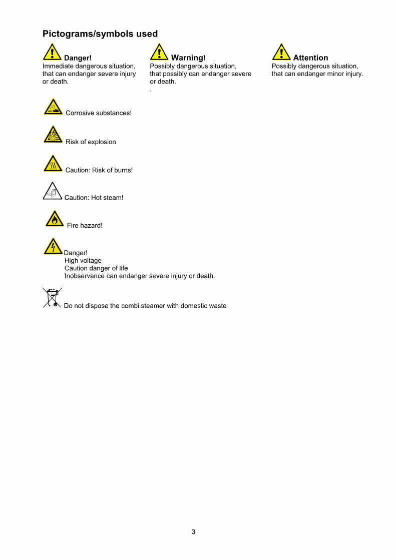
Pictograms/symbols used
Danger! Warning! Attention Immediate dangerous situation, that can endanger severe injury or death.
Possibly dangerous situation, that possibly can endanger severe or death.
Possibly dangerous situation, that can endanger minor injury.
.
Corrosive substances!
Risk of explosion
Caution: Risk of burns!
Caution: Hot steam!
Fire hazard!
Danger! High voltage Caution danger of life Inobservance can endanger severe injury or death.
Do not dispose the combi steamer with domestic waste
4
1. Safety information - Installing the appliance incorrectly, making incorrect settings on it or modifying
it can lead to damage, injury or even death. - Read the installation and operating instructions for the combi steamer through carefully
before starting it up.
Use for intended purpose
- Eloma combi steamers may only be used for preparing food in commercial kitchens. - Every other usage is against definition and therefore dangerous.
Method of operation
- The combi steamer enables you to prepare food goods using the best possible cooking chamber environment. This means the ability to adjust temperature and humidity levels exactly as required for each type of food good.
- At the same time, the required cooking method can be selected using the Scout feature on the operating panel.
- The cooking chamber temperature can be set as required to between 30°C and 300°C, and the humidity level to between 0% and 100%. The large number of setting options available enables a wide range of cooking methods to be used.
- The Genius is ideal for steaming, stewing, roasting, baking, grilling, gratinating, poaching, regenerating, defrosting and much more.
Operation
- Keep this manual in a place where it can be accessed by all users of the appliance at any time.
The combi steamer must only be operated
- By trained staff - For its intended purpose as outlined in the operating instructions, and whilst in perfect working
order. - To prevent the risk of accidents or damage to the appliance, it is essential that operating staff are
given training and health and safety briefings on a regular basis. - If the machine is set up outside, it must be ensured that it is adequately protected from rain,
thunder storms and lightening. It must be set up on a solid foundation to ensure stability. It must also be ensured that the machine is only accessible for qualified personnel.
The appliance must not be operated
- By children or persons with impaired physical, sensory or mental abilities, or by persons who do not have the requisite experience and/or knowledge, unless they are being supervised by a person who is responsible for their safety or are receiving instructions in how to use the appliance from this person.
- At an ambient temperature of < +4°C - In toxic atmospheres or atmospheres where there is a risk of explosion - With food containing highly flammable ingredients (e.g. alcohol)
Gas appliances
- The gas outlet pipe and its cover can reach high temperatures on gas appliances. - Waste gas and hot sheet metal parts can cause burns. - Do not place any flammable materials over the appliance. - If the appliance has been installed under a hood, this must be turned on during cooking. - When connecting to a chimney with flow protection, the exhaust line must be cleaned on a
regular basis (in accordance with country-specific regulations). - Only operate gas combi steamers when wind conditions are calm.
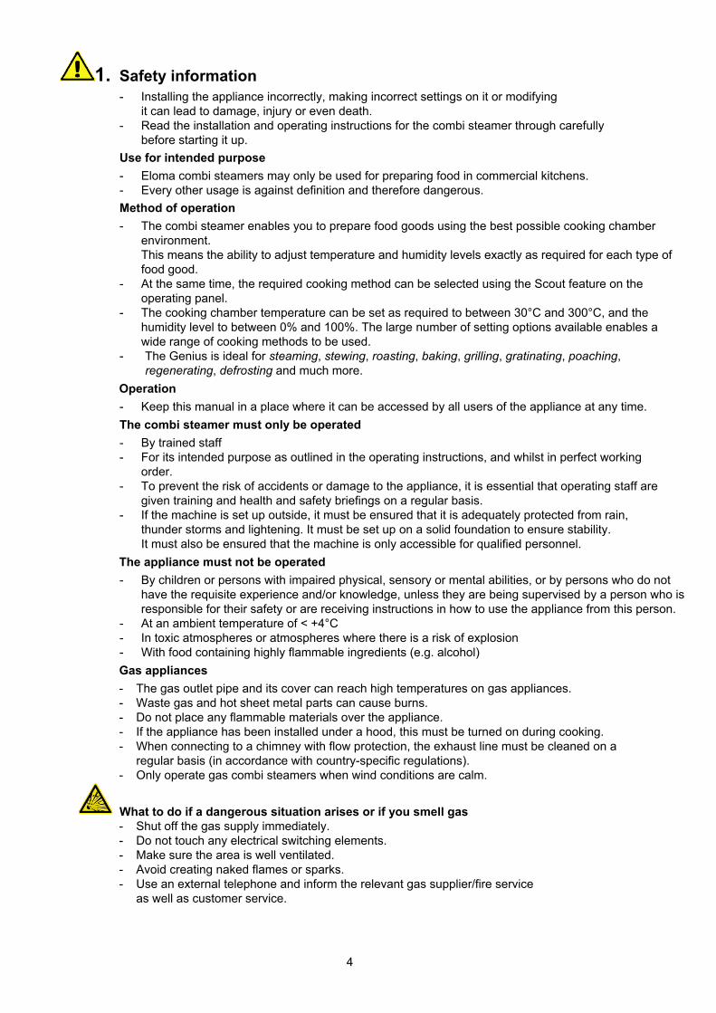
What to do if a dangerous situation arises or if you smell gas - Shut off the gas supply immediately. - Do not touch any electrical switching elements. - Make sure the area is well ventilated. - Avoid creating naked flames or sparks. - Use an external telephone and inform the relevant gas supplier/fire service
as well as customer service.
5
- Only authorised customer service personnel may open the side wall and carry out repairs and maintenance work.
Risk of injury Installation
- Please refer to the installation instructions for precise information on how to install the appliance.
- Only authorised customer service personnel may install appliances, put them into operation and perform maintenance work on them.
Appliance defects - If the glass part of the door is damaged, the appliance must not be started up.
Contact customer service. - If malfunctions occur, disconnect the appliance from the mains and close the water shut-off
valve. Contact customer service.
Notes on maintenance - The maintenance must be carried out at least once every year in accordance with national
applicable standards and regulations. - We recommend that you agree a maintenance contract for this purpose. - If the appliance is not going to be used for a prolonged period, turn it off, disconnect it from the
mains and close the water tap.
Hand shower with automatic pull-back- Pull the hand shower out until you hear it click; this means that it is locked in the correct
position for operation. - To retract the hose, pull it out until it stops making a clicking noise. - The hose will retract automatically. Water will only flow when the hose is locked in the
correct position for operation. - You should only ever allow the shower head to slide back into its resting position slowly.
Before turning on
- If the combi steamer has been transported at outside temperatures of < +4°C, the appliance's safety temperature limiter may have been triggered. This must be reset by a qualified electrician.
- Lock the air baffle in place. Never reach behind the air baffle during operation and never attempt to stop fans manually.
- Lock the rack or mobile tray rack in place correctly.
6
2. Equipment set up Transport of units
Use elevating truck or fork–lift truck for transport. Transport only on pallets.
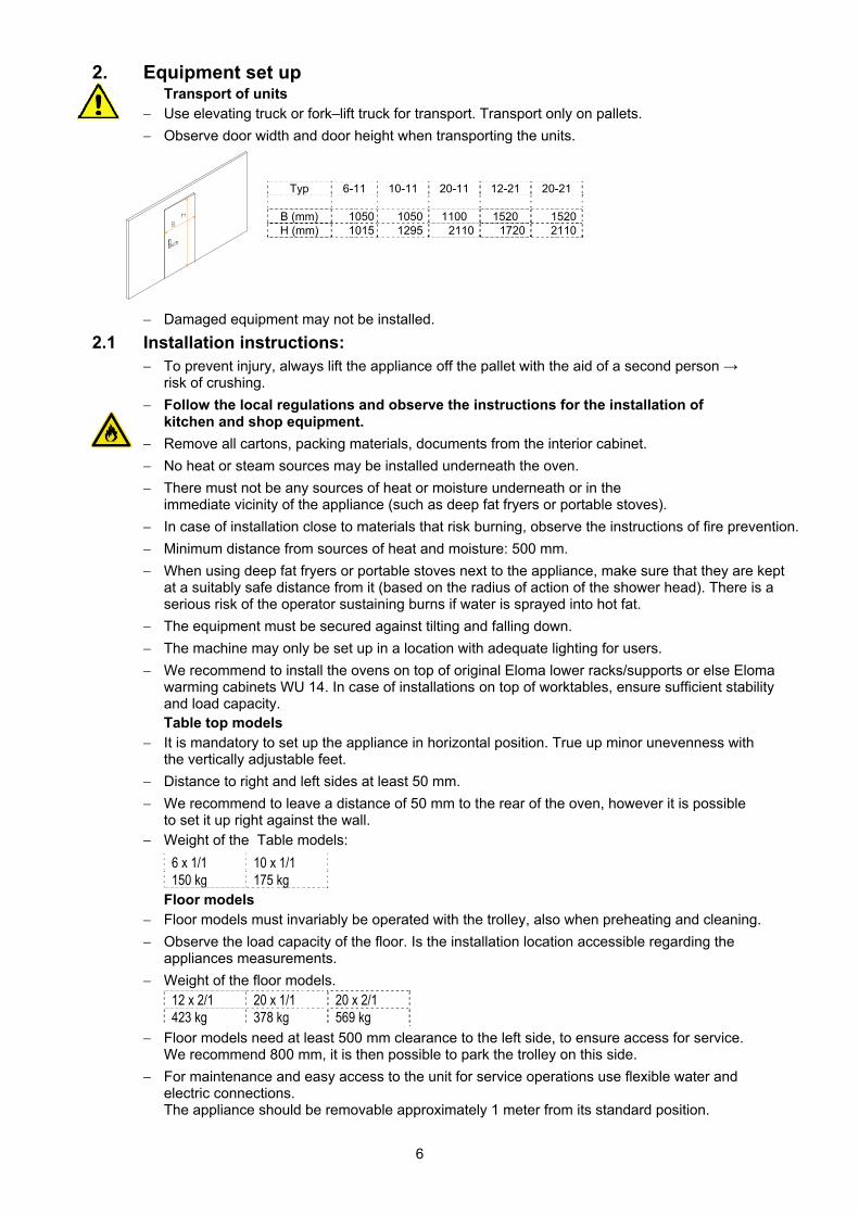
Observe door width and door height when transporting the units.
Typ 6-11 10-11 20-11 12-21 20-21
B (mm) 1050 1050 1100 1520 1520H (mm) 1015 1295 2110 1720 2110
Damaged equipment may not be installed.
2.1 Installation instructions: To prevent injury, always lift the appliance off the pallet with the aid of a second person →
risk of crushing.
Follow the local regulations and observe the instructions for the installation of kitchen and shop equipment.
Remove all cartons, packing materials, documents from the interior cabinet.
No heat or steam sources may be installed underneath the oven.
There must not be any sources of heat or moisture underneath or in the immediate vicinity of the appliance (such as deep fat fryers or portable stoves).
In case of installation close to materials that risk burning, observe the instructions of fire prevention.
Minimum distance from sources of heat and moisture: 500 mm.
When using deep fat fryers or portable stoves next to the appliance, make sure that they are kept at a suitably safe distance from it (based on the radius of action of the shower head). There is a serious risk of the operator sustaining burns if water is sprayed into hot fat.
The equipment must be secured against tilting and falling down.
The machine may only be set up in a location with adequate lighting for users.
We recommend to install the ovens on top of original Eloma lower racks/supports or else Eloma warming cabinets WU 14. In case of installations on top of worktables, ensure sufficient stability and load capacity. Table top models
It is mandatory to set up the appliance in horizontal position. True up minor unevenness with the vertically adjustable feet.
Distance to right and left sides at least 50 mm.
We recommend to leave a distance of 50 mm to the rear of the oven, however it is possible to set it up right against the wall.
Weight of the Table models:
6 x 1/1 10 x 1/1 150 kg 175 kg
Floor models Floor models must invariably be operated with the trolley, also when preheating and cleaning.
Observe the load capacity of the floor. Is the installation location accessible regarding the appliances measurements.
Weight of the floor models. 12 x 2/1 20 x 1/1 20 x 2/1 423 kg 378 kg 569 kg
Floor models need at least 500 mm clearance to the left side, to ensure access for service. We recommend 800 mm, it is then possible to park the trolley on this side.
For maintenance and easy access to the unit for service operations use flexible water and electric connections. The appliance should be removable approximately 1 meter from its standard position.
7
2.2 Hints for setting up The floor underneath the appliance must be plane to ensure a smooth driving-in of the trolley
(roll-in pan-rack).
The trolley must be pane in the unit.
Fix the appliance after adjusting the level and angle, so that the oven can’t shift anymore.
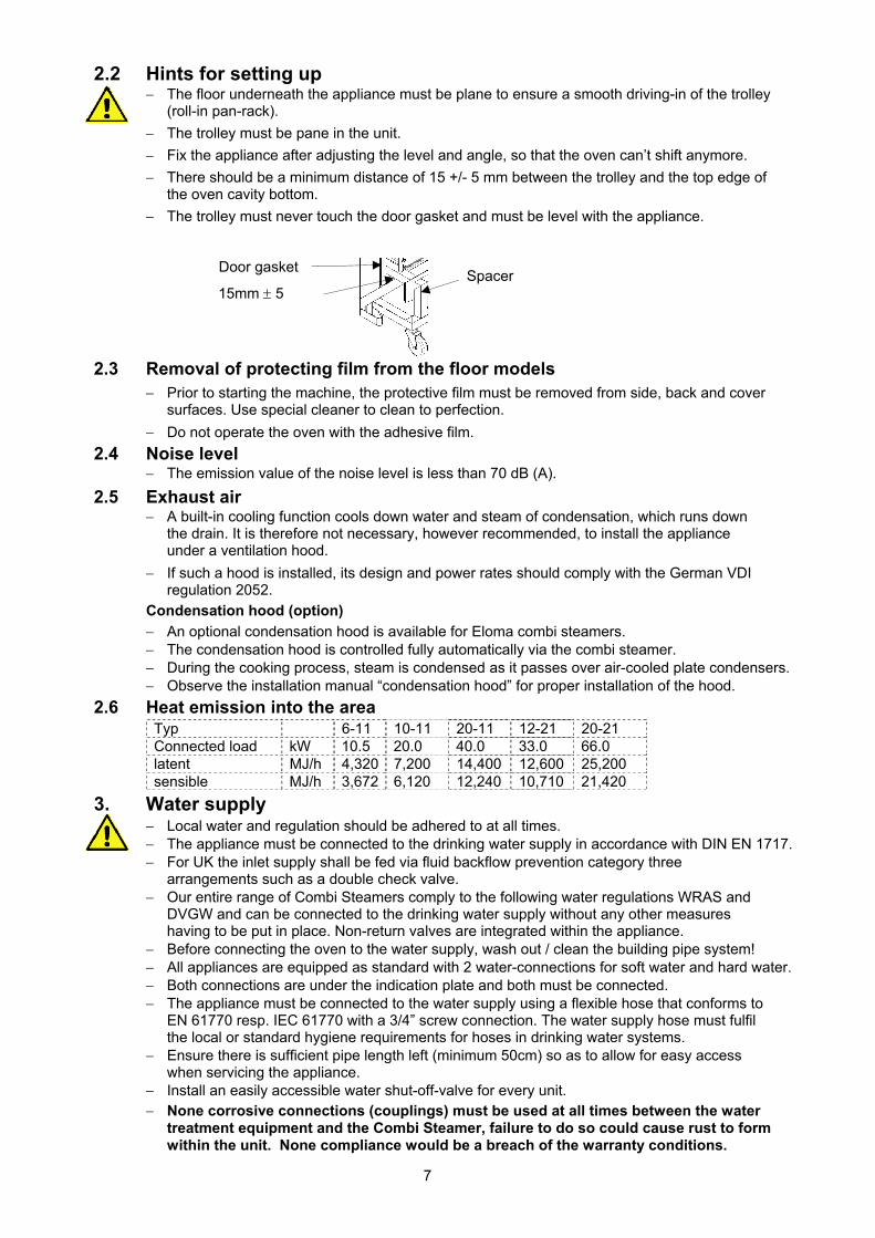
There should be a minimum distance of 15 +/- 5 mm between the trolley and the top edge of the oven cavity bottom.
The trolley must never touch the door gasket and must be level with the appliance.
2.3 Removal of protecting film from the floor models Prior to starting the machine, the protective film must be removed from side, back and cover
surfaces. Use special cleaner to clean to perfection.
Do not operate the oven with the adhesive film.
2.4 Noise level The emission value of the noise level is less than 70 dB (A).
2.5 Exhaust air A built-in cooling function cools down water and steam of condensation, which runs down
the drain. It is therefore not necessary, however recommended, to install the appliance under a ventilation hood.
If such a hood is installed, its design and power rates should comply with the German VDI regulation 2052.
Condensation hood (option)
An optional condensation hood is available for Eloma combi steamers. The condensation hood is controlled fully automatically via the combi steamer. During the cooking process, steam is condensed as it passes over air-cooled plate condensers. Observe the installation manual “condensation hood” for proper installation of the hood.
2.6 Heat emission into the area Typ 6-11 10-11 20-11 12-21 20-21 Connected load kW 10.5 20.0 40.0 33.0 66.0 latent MJ/h 4,320 7,200 14,400 12,600 25,200 sensible MJ/h 3,672 6,120 12,240 10,710 21,420
3. Water supply Local water and regulation should be adhered to at all times. The appliance must be connected to the drinking water supply in accordance with DIN EN 1717. For UK the inlet supply shall be fed via fluid backflow prevention category three
arrangements such as a double check valve. Our entire range of Combi Steamers comply to the following water regulations WRAS and
DVGW and can be connected to the drinking water supply without any other measures having to be put in place. Non-return valves are integrated within the appliance.
Before connecting the oven to the water supply, wash out / clean the building pipe system! All appliances are equipped as standard with 2 water-connections for soft water and hard water. Both connections are under the indication plate and both must be connected. The appliance must be connected to the water supply using a flexible hose that conforms to
EN 61770 resp. IEC 61770 with a 3/4” screw connection. The water supply hose must fulfil the local or standard hygiene requirements for hoses in drinking water systems.
Ensure there is sufficient pipe length left (minimum 50cm) so as to allow for easy access when servicing the appliance.
Install an easily accessible water shut-off-valve for every unit. None corrosive connections (couplings) must be used at all times between the water
treatment equipment and the Combi Steamer, failure to do so could cause rust to form within the unit. None compliance would be a breach of the warranty conditions.
Door gasket
15mm 5 Spacer
8
3.1 In coming water supply quality Check the water quality and water hardness with your local water supply company before
commencing with installation.
The Incoming water quality should not exceed the following limits. With water it is necessary to know about the ingredients and their effects. Total hardness: ≤ 3° dH pH- value: 7,0 bis 8,5 conductivity: ≤ 90 µS/cm Cl- : Max. 60 mg/l SO4: Max. 100 mg/l SiO4: Max. 10 mg/l Fe: Max. 0,05 mg/l Mn: Max. 0,05 mg/l Cu: Max. 0,05 mg/l Cl2: Max. 0,10 mg/l
Soft water connection:
If the total water hardness is ≥ 3° dH at least one hydrogen ion exchanger must be connected upstream from the soft water connection on the machine. For our units approved filter systems are partial demineralisation filters with integrated particle and activated carbon filtration as well as a bypass.
Among others, Brita offers adequate filter systems.
Sodium ion exchangers (as normally used for dishwashers) are not permitted for our machines. The glass window can become dull and stainless steel components in the cooking chamber could be irreparably damaged!
Systems with silicate metering must not be used. They can cause malfunctions and scaling in the cooking chamber.
Systems that operate with electromagnetic fields do not protect against lime scale in this type of machine.
If the total water hardness is < 3° dH but the water contains impurities such as sand, iron particles or suspended particles, a 5 - 15 µm fine filter must be installed upstream from the soft water connection on the machine.
If the water is chlorinated Cl2 in excess of 0.1 mg/l (corresponding to 0.1 ppm), an activated carbon filter must be additionally installed upstream from the soft water connection on the machine. Activated carbon filters may also be an integral part of fine filters.
Hard water connection:
If the water contains impurities such as sand, iron particles or suspended particles, a 5 - 15 µm fine filter must be installed upstream from the hard water connection of the machine.
If the water is chlorinated Cl2 in excess of 0.1 mg/l (corresponding to 0.1 ppm), an activated carbon filter must be additionally installed upstream from the hard water connection on the machine.
Activated carbon filters may also be an integral part of fine filters.
Special requirements:
If the chloride Cl- concentration is in excess of 60 mg/l (corresponding to 60 ppm) and/or the concentration of silicate (SiO4) is ≥ 10 mg/l, there is a greater risk of corrosion. Thus the water for the entire water supply of the device must be treated with a reversed osmosis system. Make sure that the reference value of 10 µS/cm is maintained, as totally pure water is too aggressive and would cause severe damages.
Reverse osmosis systems can be an alternative to full and/or partial demineralisation systems. Reverse osmosis systems remove almost all water-hardening substances and non-hardening minerals from the water.
If a combination of filters and water treatment system is installed, the following components must be installed in the specified order: sediment filter, hydrogen ion exchanger with activated carbon filter, shut-off valve.
Regular maintenance and cartridge replacement on all forms of water treatment is vitally important. Damages to Eloma machines resulting from neglect of maintenance will void any warranty claims.
9
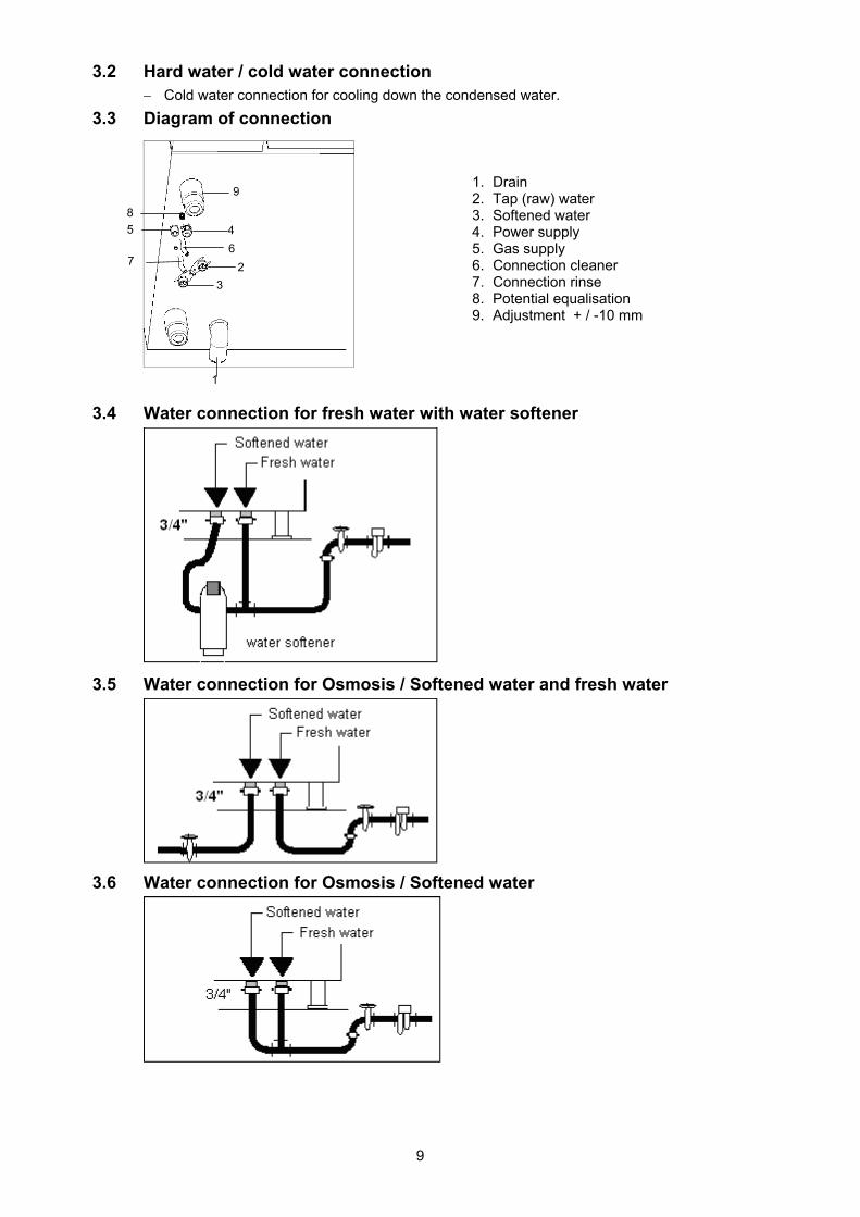
3.2 Hard water / cold water connection Cold water connection for cooling down the condensed water.
3.3 Diagram of connection
3.4 Water connection for fresh water with water softener
3.5 Water connection for Osmosis / Softened water and fresh water
3.6 Water connection for Osmosis / Softened water
1. Drain 2. Tap (raw) water 3. Softened water 4. Power supply 5. Gas supply 6. Connection cleaner 7. Connection rinse 8. Potential equalisation 9. Adjustment + / -10 mm
1
2
4
3
9
5
7
8
6
10
3.7 Water pressure
Min. 200 kPa = 2 bar Max. 600 kPa = 6 bar
3.8 Max. flow rate
Typ 6-11 10-11 12-21 20-11 20-21Softened water l/h 15 20 25 40 50 Hard water l/h 55 55 55 65 65
3.9 Water hardness conversion table 1°d = 0.18 mmol/l (ISO unit) 1°d = 10 CaO 1°d = 1.79 °fH (France) 1°d = 1.25 °eH (UK) 1°d = 7.14 °H (USSR) 1°d = 1.04 °aH (USA)
4. Autoclean (Optional Equipment)
Please use only Eloma MULTI-CLEAN spezial detergent and Eloma MULTI-CLEAN Klarspüler rinse aid for cleaning your Eloma equipment. The Eloma distributed detergents and rinse-aids contain special components with exact measurements that are specifically synchronized and tested for optimal results with Eloma machines.
Other cleaning products can possibly cause irreparable rust damages in the cooking chamber, as well as damage pumps and seals.
Eloma GmbH cannot assume liability for any damages resulting from the use of alternative products. This will void the Eloma warranty.
Connection
Refer to the dimensioned sketch for connections of cleaning and rinse agent.
The label on the oven indicates where the chemicals have to be connected.
Use the supplied clamps to connect the hoses to the oven.
Red for the cleaner and blue for the rinse agent
Handling of cleaner and rinse agent: Observe the directions of the manufacturer and wear suitable protective clothing, gloves and glasses.
Canisters must be positioned below the bottom edge of the combi steamer. They must never be positioned above this.
Maximum vertical range from canister to connection = 1,50 m. Maximum hose length = 10 m.
Remove the lids of the two canisters (cleaner and rinse agent) and screw the screw cap with hose to the respective canister. Red for the cleaner and blue for the rinse agent.
Start the installation program Autoclean. Check if cleaner and rinse agent are sucked into the cooking chamber. If necessary, please repeat the Autoclean “start up” level. Autoclean is ready for use.
To detailed data and function of Autoclean see operation manual of the combi-steamer.
Reiniger Klarspüler Cleaner Rinse agent Nettoyant Rince-éclat
11
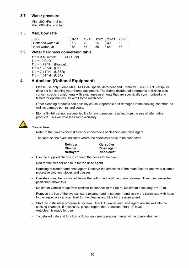
5. Drain connection
Local water and regulation should be adhered.
Connect drain to the waste water system in accordance with the German standard DIN 1986, section 1.
The appliance complies with the relevant regulations
Drain and air-vent pipe material must be steam temperature resistant. Minimum diameter 50 mm, preferably not longer than 1 m, we recommend high temperature resistant pipes type HT PA-I 1818 according to the German standard DIN 19560. It is not permitted to taper the cross-section of the drain.
Slope of at least 5% is necessary.
Waste water temperature 80°C
To fill the siphon, give about 3 liters of clear water into the oven prior to any first start.
Fixed connection without trap
Fixed connection with trap
Drain fannel
The Eloma GmbH bears no liability for any damages caused by a not proper installation.
12
6. Electrical connection EZ und Potential equalisation PE
Do not connect the unit to the mains if it has just been transported from a cold environment into a warm room. Otherwise condensate may develop inside the combi steamer which may cause damages.
Wait for about two hours until the unit has reached room temperature
Electrical connections must be carried out by an approved electrician in accordance with VDE regulations and regulations of the local electricity supply companies
Pay attention to the data on the type plate for the electrical connections.
6.1 Electrical connection data gas units
Typ 6-11 10-11 20-11 12-21 20-21 Heat load gas kW 12.0 20.0 40.0 35.0 70.0 Connected load electric
kW 0,6 0,7 1,6 1,1 1,9
Voltage 230 V 1 N AC 50 Hz Fuse protection Amp. 1x10 1x10 1x16 1x10 1x16
USA Typ 6-11 10-11 20-11 12-21 20-21 Power/Gas BTU/h 41000 68000 136000 119000 239000 Connected load electric
kW 1 1 2 1 2
Voltage 120 V 1 N AC 50/60 Hz
The table models units are supplied with a connecting cable, length 2 m. In case this cable has to be replaced for whatever reason, use a cable type H07RN-F according to German VDE standards.
Next to the appliance an all-pole electric circuit breaker with a contact opening of at least 3mm has to be provided for on site.
The appliance must be incorporated into the potential equalisation system (ground).
In case a plug is mounted, the plug device must be accessible after setting-up.
Please note:
Do not fit a mains plug to the mains cable. Securely connect the mains cable to prevent phase distortion.
Connect the phase to the brown cable (L), otherwise failures in the gas system will occur. In such case the symbol “failure gas system“ would be displayed.
13
7. Installation instructions
7.1 Setting–up possibilities
The DVGW (DVGW = German technical scientific association on gas and water) and the Technical regulations for liquid gas installations TRGI G 600 give systematic information about the different types of gas appliances, their exhaust gas evacuation and their combustion air supply. Consequently, do observe vigorously the local regulations, prescriptions and standards of your country for the installation of catering gas appliances. Prior to setting up discuss the construction of the exhaust gas system with the local chimney-sweep in charge and record the approved construction.
Appliances of Type A are defined as units that can be operated without exhaust gas evacuation installations. (A 3 with blower before the burner)
Appliances of Type B are defined as units that must be operated with exhaust gas evacuation installations. (B13, B23 with blower before the burner)
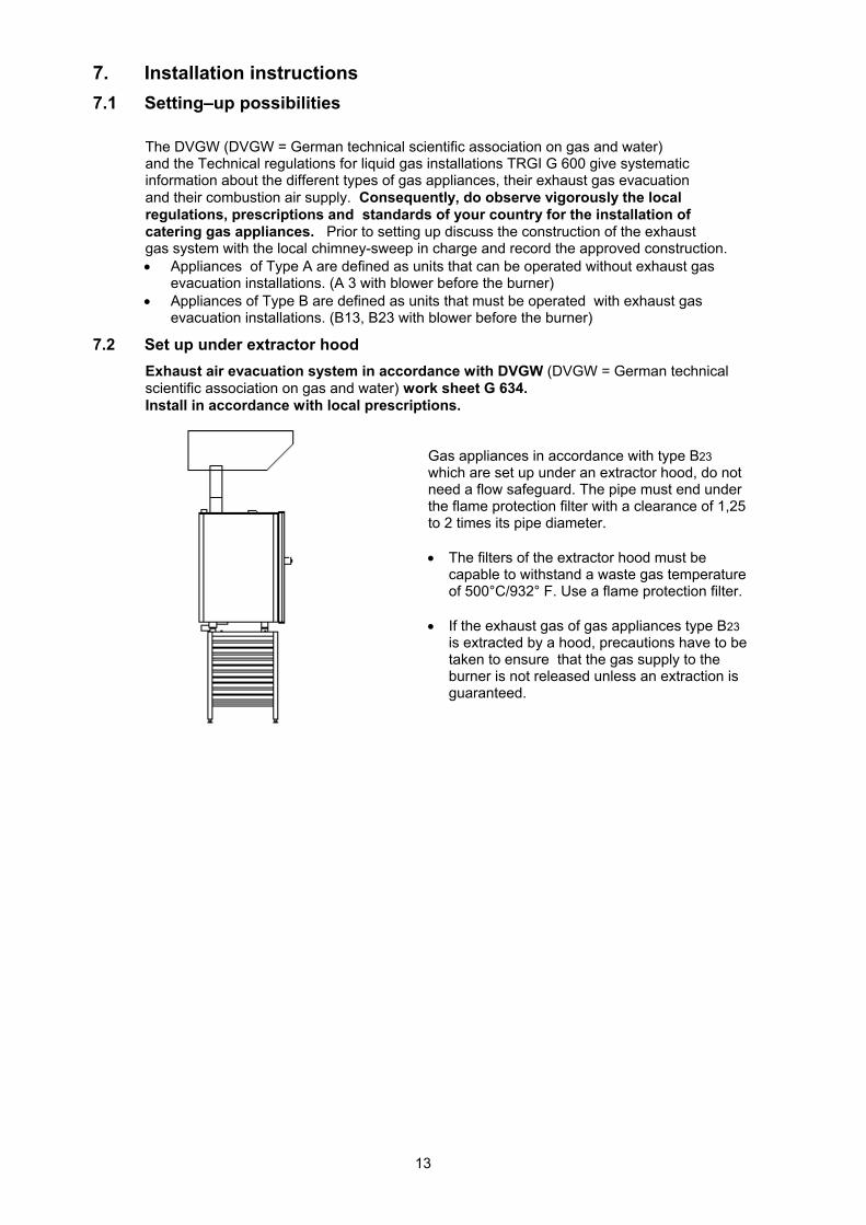
7.2 Set up under extractor hood
Exhaust air evacuation system in accordance with DVGW (DVGW = German technical scientific association on gas and water) work sheet G 634. Install in accordance with local prescriptions.
Gas appliances in accordance with type B23
which are set up under an extractor hood, do not need a flow safeguard. The pipe must end under the flame protection filter with a clearance of 1,25 to 2 times its pipe diameter.
The filters of the extractor hood must be capable to withstand a waste gas temperature of 500°C/932° F. Use a flame protection filter.
If the exhaust gas of gas appliances type B23
is extracted by a hood, precautions have to be taken to ensure that the gas supply to the burner is not released unless an extraction is guaranteed.
14
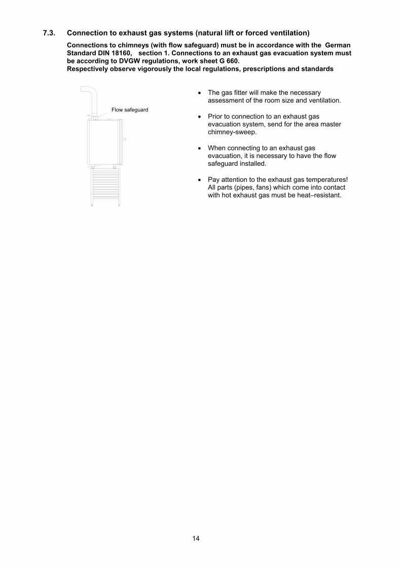
7.3. Connection to exhaust gas systems (natural lift or forced ventilation)
Connections to chimneys (with flow safeguard) must be in accordance with the German Standard DIN 18160, section 1. Connections to an exhaust gas evacuation system must be according to DVGW regulations, work sheet G 660. Respectively observe vigorously the local regulations, prescriptions and standards
The gas fitter will make the necessary
assessment of the room size and ventilation.
Prior to connection to an exhaust gas evacuation system, send for the area master chimney-sweep.
When connecting to an exhaust gas evacuation, it is necessary to have the flow safeguard installed.
Pay attention to the exhaust gas temperatures! All parts (pipes, fans) which come into contact with hot exhaust gas must be heat–resistant.
Flow safeguard
15
8 Connect mains cable
Connection, conversion and repair of gas–consuming equipment in catering kitchens and the remedying of faults in equipment of this type, may only be carried out by - the gas supply company, - a skilled representative of the manufacturer (with DVGW or any local certificate), - a contract installation company or - a sales organisation authorised by a liquid gas distribution company.
Before making any connections, inform the responsible gas supply company.
Observe the Technical regulations for gas installations DVGW TRGI! (DVGW = German technical scientific association on gas and water) and refer to work sheets G 600, G 628, G 634, G 660, G 670 and the Technical regulations for liquid gas TRGI. Respectively observe the technical regulations and instruction for gas installations of your country.
For USA Gas lines and connections should be sized according to the charts referenced in NFPA # 54 or the local authority having jurisdiction. Please note: For correct sizing of the gas line, following points must taken into the consideration:
1) total load of the kitchen 2) individual firing rates of each appliance being serviced by the gas line and meter. 3) The distance between the last appliance being serviced and the gas meter 4) Last the number of fittings in the gas line for that distance.
The installation must be carried out in accordance with the manufacturer’s assembly instructions and in accordance with recognised technical rules.
The installation of different makes and different types of individual burner parts and of so–called gas saver units is not permitted.
Before the combi steamer, a gas shut–off valve must be provided for on site.
Before connecting, ensure that the set gas type of the appliance is the same as the gas type available at the site of installation.
If operating with liquid gas, the installation of the combi steamer below ground level is prohibited.
Ensure that mains connection is protected from mechanical damages and heat.
Units with a fixed (rigid) connection must be secured to prevent being moved around.
Check the gas line pressure.
After setting up, converting and repairing gas consuming appliances, check all parts carrying gas for leaks.
Do not spray foaming spray on the flame monitoring control’s wires.
When setting up the combi steamer for the first time, refer to the information plate
Important!
To ensure that the burner settings made at the factory conform with the actual installation conditions, the waste gas (CO, CO2) from the gas combisteamer must be analysed during commissioning.
The burner settings must be checked and if necessary adjusted by an authorized service in accordance with the commissioning report for gas combi steamer.
The verified parameters and the new values must be documented in the commissioning protocol. See also checklist service manual.
16
9. Initial start-up
The initial start up procedure must also be carried out when setting up unit, after longer operational interruptions or after maintenance work (filling of gas inlet).
Insert fat filter and drain sieve into the cooking chamber
Insert left and right hand-in racks into the cooking chamber.
Follow the instructions for using the water softener
Turn the airventilation on.
Open the gas shut–off valve at the installation site.
Switch on the combi steamer, set temperature 300°C, 100 % humidity and time 1:00 houers and start.
If there is not sufficient gas available in the gas supply line - the combi steamer blocks the gas supply - a buzzer sounds and - the Info line displays the symbol “no flame“
Allow the buzzer to sound for approx. 5–7 seconds.
On combisteamer Genius T gas press sensor key “restart gas“.
On combisteamer Multimax B gas Use key to acknowledge gas fault messages gas-combisteamer starts automatically.
The failure indicator responds several times in the case of long gas supply lines.
It is therefore necessary to restart several times.
17
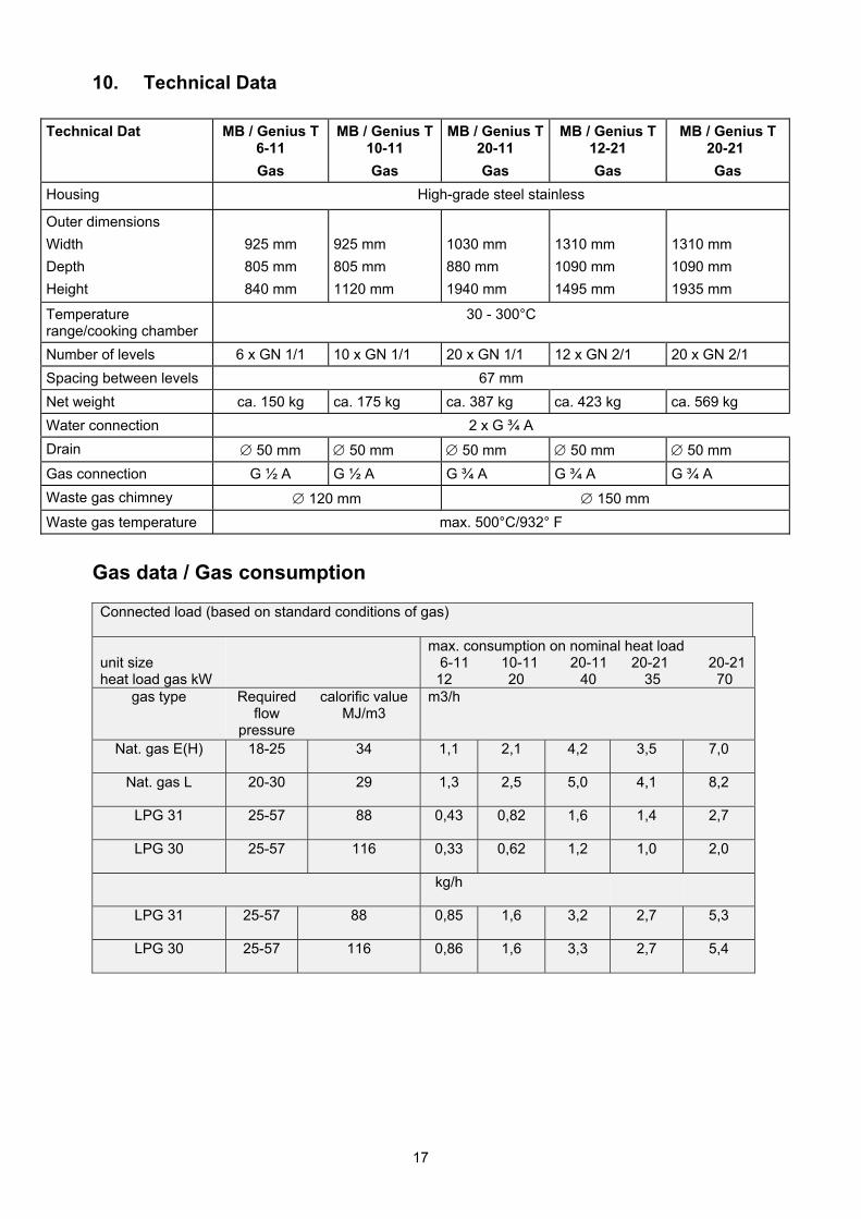
10. Technical Data
Technical Dat MB / Genius T 6-11
Gas
MB / Genius T 10-11
Gas
MB / Genius T 20-11
Gas
MB / Genius T 12-21
Gas
MB / Genius T 20-21
Gas
Housing High-grade steel stainless
Outer dimensions
Width
Depth
Height
925 mm
805 mm
840 mm
925 mm
805 mm
1120 mm
1030 mm
880 mm
1940 mm
1310 mm
1090 mm
1495 mm
1310 mm
1090 mm
1935 mm
Temperature range/cooking chamber
30 - 300°C
Number of levels 6 x GN 1/1 10 x GN 1/1 20 x GN 1/1 12 x GN 2/1 20 x GN 2/1
Spacing between levels 67 mm
Net weight ca. 150 kg ca. 175 kg ca. 387 kg ca. 423 kg ca. 569 kg
Water connection 2 x G ¾ A
Drain 50 mm 50 mm 50 mm 50 mm 50 mm
Gas connection G ½ A G ½ A G ¾ A G ¾ A G ¾ A
Waste gas chimney 120 mm 150 mm
Waste gas temperature max. 500°C/932° F
Gas data / Gas consumption
Connected load (based on standard conditions of gas)
unit size heat load gas kW
max. consumption on nominal heat load 6-11 10-11 20-11 20-21 20-21 12 20 40 35 70
gas type Required flow
pressure
calorific valueMJ/m3
m3/h
Nat. gas E(H) 18-25 34 1,1 2,1 4,2 3,5 7,0
Nat. gas L 20-30 29 1,3 2,5 5,0 4,1 8,2
LPG 31 25-57 88 0,43 0,82 1,6 1,4 2,7
LPG 30 25-57 116 0,33 0,62 1,2 1,0 2,0
kg/h
LPG 31 25-57 88 0,85 1,6 3,2 2,7 5,3
LPG 30 25-57 116 0,86 1,6 3,3 2,7 5,4
18
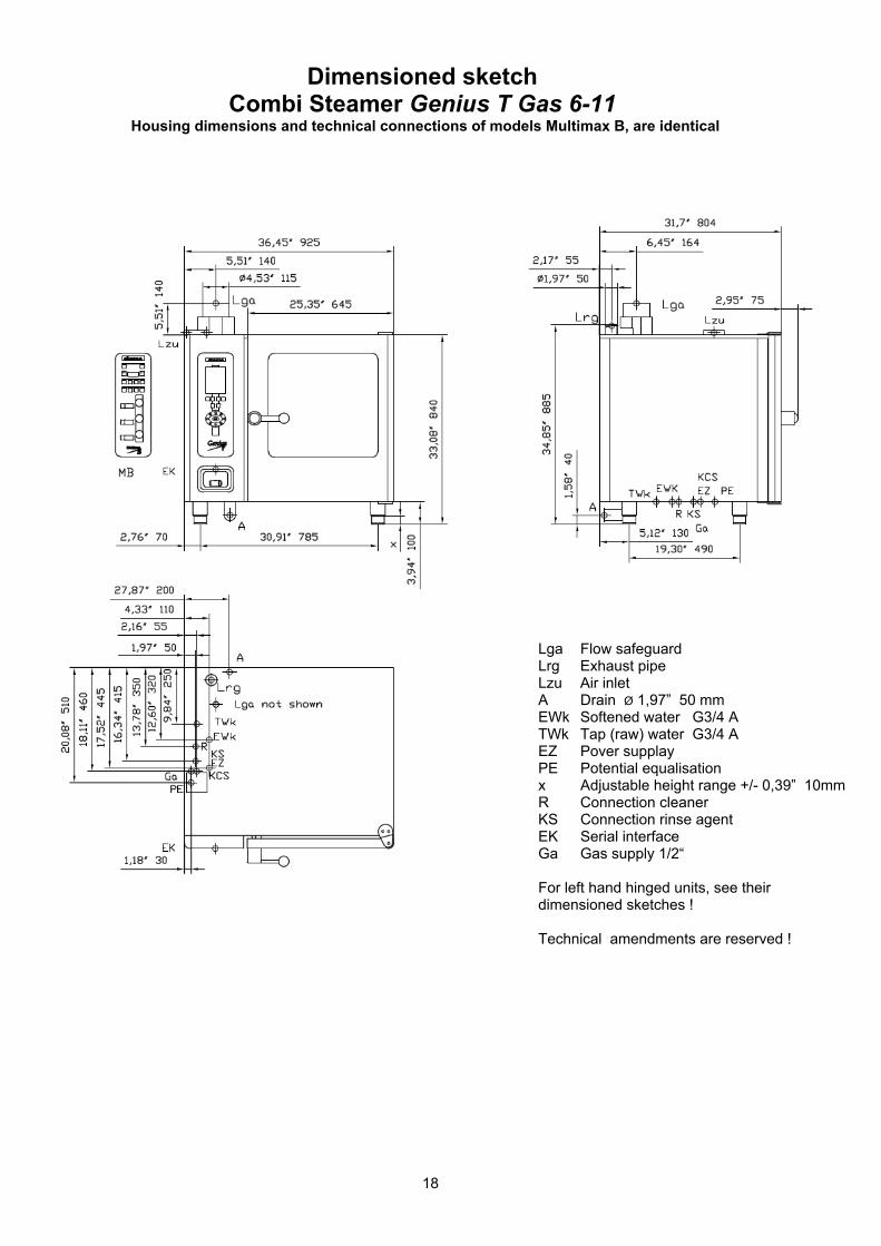
Dimensioned sketch Combi Steamer Genius T Gas 6-11
Housing dimensions and technical connections of models Multimax B, are identical
Lga Flow safeguard Lrg Exhaust pipe Lzu Air inlet A Drain Ø 1,97” 50 mm EWk Softened water G3/4 A TWk Tap (raw) water G3/4 A EZ Pover supplay PE Potential equalisation x Adjustable height range +/- 0,39” 10mm R Connection cleaner KS Connection rinse agent EK Serial interface Ga Gas supply 1/2“
For left hand hinged units, see their dimensioned sketches !
Technical amendments are reserved !
19
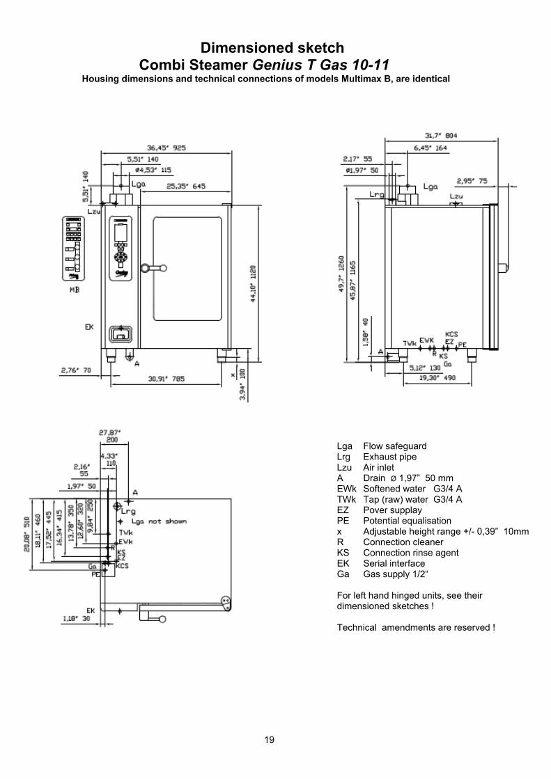
Dimensioned sketch Combi Steamer Genius T Gas 10-11
Housing dimensions and technical connections of models Multimax B, are identical
Lga Flow safeguard Lrg Exhaust pipe Lzu Air inlet A Drain Ø 1,97” 50 mm EWk Softened water G3/4 A TWk Tap (raw) water G3/4 A EZ Pover supplay PE Potential equalisation x Adjustable height range +/- 0,39” 10mm R Connection cleaner KS Connection rinse agent EK Serial interface Ga Gas supply 1/2“
For left hand hinged units, see their dimensioned sketches !
Technical amendments are reserved !
20
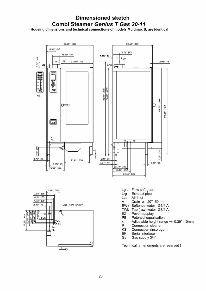
Dimensioned sketch Combi Steamer Genius T Gas 20-11
Housing dimensions and technical connections of models Multimax B, are identical
Lga Flow safeguard Lrg Exhaust pipe Lzu Air inlet A Drain Ø 1,97” 50 mm EWk Softened water G3/4 A TWk Tap (raw) water G3/4 A EZ Pover supplay PE Potential equalisation x Adjustable height range +/- 0,39” 10mm R Connection cleaner KS Connection rinse agent EK Serial interface Ga Gas supply 3/4“
Technical amendments are reserved !
21
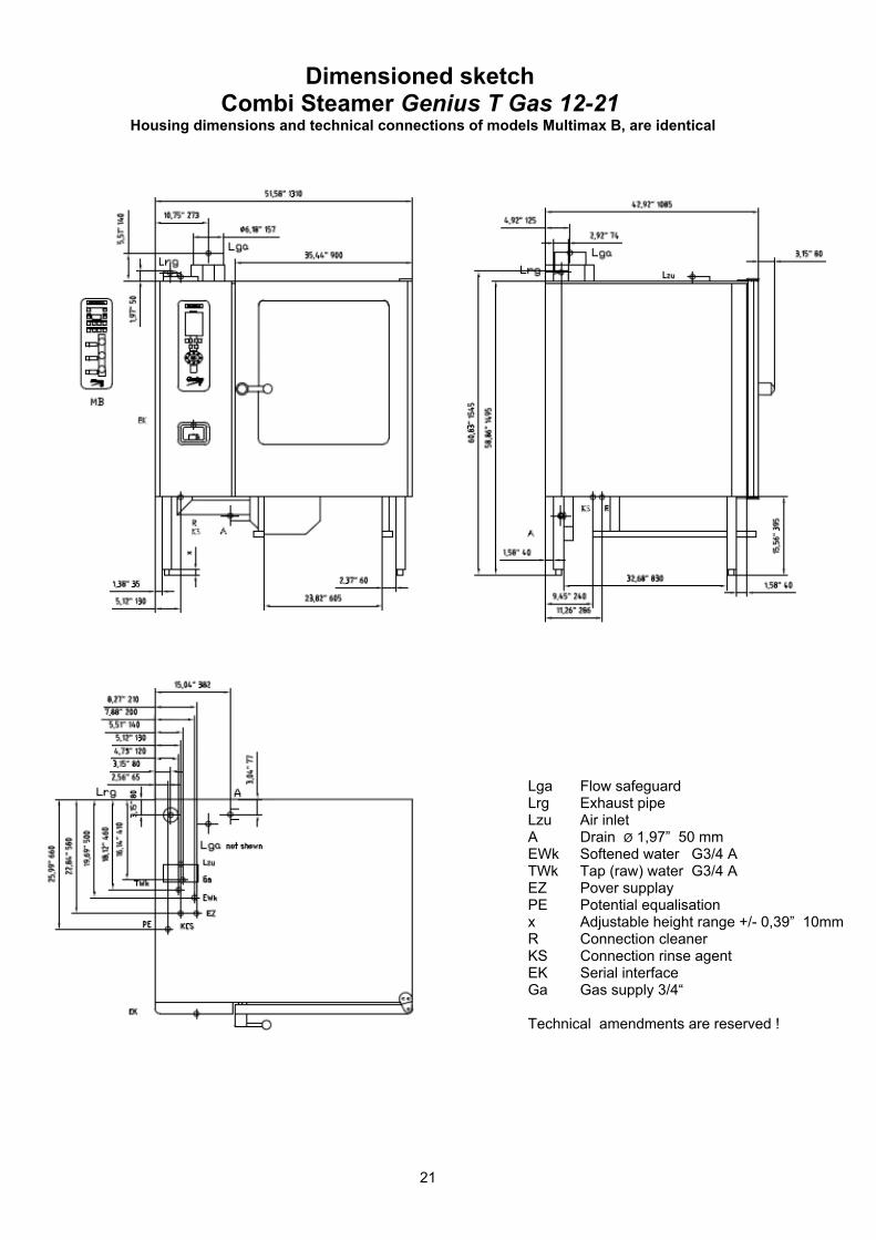
Dimensioned sketch Combi Steamer Genius T Gas 12-21
Housing dimensions and technical connections of models Multimax B, are identical
Lga Flow safeguard Lrg Exhaust pipe Lzu Air inlet A Drain Ø 1,97” 50 mm
EWk Softened water G3/4 A TWk Tap (raw) water G3/4 A
EZ Pover supplay PE Potential equalisation
x Adjustable height range +/- 0,39” 10mm R Connection cleaner
KS Connection rinse agent EK Serial interface
Ga Gas supply 3/4“
Technical amendments are reserved !
22
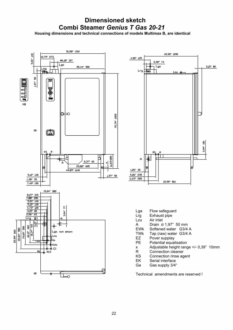
Dimensioned sketch Combi Steamer Genius T Gas 20-21
Housing dimensions and technical connections of models Multimax B, are identical
Lga Flow safeguard Lrg Exhaust pipe Lzu Air inlet A Drain Ø 1,97” 50 mm
EWk Softened water G3/4 A TWk Tap (raw) water G3/4 A
EZ Pover supplay PE Potential equalisation
x Adjustable height range +/- 0,39” 10mm R Connection cleaner
KS Connection rinse agent EK Serial interface
Ga Gas supply 3/4“
Technical amendments are reserved !
23
Notes:

24
Notes:


Englisch Art. Nr.: ins_EL0791342_mb_gt_g_2v8_enus