Embed Size (px)
Citation preview

ELTR 140 (Digital 1), section 2
Recommended schedule
Day 1Topics: Boolean algebra, basic concepts and identitiesQuestions: 1 through 20Lab Exercise: work on project
Day 2Topics: Boolean algebra, simplification lawsQuestions: 21 through 40Lab Exercise: Gate circuit from Boolean expression (question 96)
Day 3Topics: SOP and POS expressionsQuestions: 41 through 60Lab Exercise: Gate circuit from truth table (question 97)
Day 4Topics: Karnaugh mappingQuestions: 61 through 75Lab Exercise: work on project
Day 5Topics: DeMorgan’s Theorem and gate universalityQuestions: 76 through 95Lab Exercise: NAND gate universality (question 98)
Day 6Exam 2: includes Boolean-to-gate performance assessment
Troubleshooting practice problemsQuestions: 100 through 109
General concept practice and challenge problemsQuestions: 110 through the end of the worksheet
Impending deadlinesProject due at end of ELTR140, Section 3Question 99: Sample project grading criteria
1

ELTR 140 (Digital 1), section 2
Skill standards addressed by this course section
EIA Raising the Standard; Electronics Technician Skills for Today and Tomorrow, June 1994
F Technical Skills – Digital CircuitsF.02 Demonstrate an understanding of minimizing logic circuits using Boolean operations.F.08 Understand principles and operations of combinational logic circuits.F.09 Fabricate and demonstrate combinational logic circuits.F.10 Troubleshoot and repair combinational logic circuits.
B Basic and Practical Skills – Communicating on the JobB.01 Use effective written and other communication skills. Met by group discussion and completion of labwork.B.03 Employ appropriate skills for gathering and retaining information. Met by research and preparation
prior to group discussion.B.04 Interpret written, graphic, and oral instructions. Met by completion of labwork.B.06 Use language appropriate to the situation. Met by group discussion and in explaining completed labwork.B.07 Participate in meetings in a positive and constructive manner. Met by group discussion.B.08 Use job-related terminology. Met by group discussion and in explaining completed labwork.B.10 Document work projects, procedures, tests, and equipment failures. Met by project construction and/or
troubleshooting assessments.C Basic and Practical Skills – Solving Problems and Critical Thinking
C.01 Identify the problem. Met by research and preparation prior to group discussion.C.03 Identify available solutions and their impact including evaluating credibility of information, and locating
information. Met by research and preparation prior to group discussion.C.07 Organize personal workloads. Met by daily labwork, preparatory research, and project management.C.08 Participate in brainstorming sessions to generate new ideas and solve problems. Met by group discussion.
D Basic and Practical Skills – ReadingD.01 Read and apply various sources of technical information (e.g. manufacturer literature, codes, and
regulations). Met by research and preparation prior to group discussion.E Basic and Practical Skills – Proficiency in Mathematics
E.01 Determine if a solution is reasonable.E.02 Demonstrate ability to use a simple electronic calculator.E.06 Translate written and/or verbal statements into mathematical expressions.E.12 Interpret and use tables, charts, maps, and/or graphs.E.13 Identify patterns, note trends, and/or draw conclusions from tables, charts, maps, and/or graphs.E.15 Simplify and solve algebraic expressions and formulas.E.16 Select and use formulas appropriately.E.18 Use properties of exponents and logarithms.E.21 Use Boolean algebra to break down logic circuits.
2

ELTR 140 (Digital 1), section 2
Common areas of confusion for students
Difficult concept: Boolean rules and identities.In many ways Boolean algebra is simpler than regular algebra (e.g., there is no such thing as subtraction
or division to worry about), but it is still algebra, and because of this fact many students struggle with it.Working with algebraic expressions means precisely following a specific set of absolute rules. This requiresa reliable knowledge of those rules and an ability to think rigorously. These are not easy requirements formost human beings, which is why so many people dislike mathematics. There is but one solution to thisproblem: practice, practice, and practice again. If you find yourself making algebraic mistakes, don’t giveup – that would be exactly the wrong thing to do. Learn from your mistakes, pick yourself back up, and tryagain. It can be done!
Difficult concept: Algebraic substitution.Many Boolean rules such as A + AB = A are easy enough to learn in their canonical form, but more
difficult to apply when seen in a form such as CFG + CG = CG. Fundamentally, this is a problem withthe algebraic principle of substitution: replacing one variable with a different variable or a whole expression.The key to substitution is the ability to perform visual pattern-matching, which some people have a mucheasier time with than others. Once again, the only solution to this problem is practice, practice, and morepractice. Remember that no one comes out of the womb knowing how to do this stuff! Everyone who hasany knowledge of algebra at all once started knowing nothing about it. People can learn and succeed atthis material, yourself included. Your personal journey through algebra may be more difficult than it is forothers, for any number of reasons, but it is not an impossible journey.
3

Questions
Question 1
Identify each of these logic gates by name, and complete their respective truth tables:
A B Output
00
0 1
01
1 1
A
BOutput
A B Output
00
0 1
01
1 1
A
BOutput
A B Output
00
0 1
01
1 1
A
BOutput
A B Output
00
0 1
01
1 1
A
BOutput
A B Output
00
0 1
01
1 1
A
BOutput
A B Output
00
0 1
01
1 1
A
BOutput
A B Output
00
0 1
01
1 1
A
BOutput
A B Output
00
0 1
01
1 1
A
BOutput A Output
A Output
0
1
file 02776
4

Question 2
Identify each of these relay logic functions by name (AND, OR, NOR, etc.) and complete their respectivetruth tables:
A B Output
00
0 1
01
1 1
A B Output
00
0 1
01
1 1
A B Output
00
0 1
01
1 1
A B Output
00
0 1
01
1 1
A B Output
00
0 1
01
1 1
A B Output
00
0 1
01
1 1
A B Output
00
0 1
01
1 1
A B Output
00
0 1
01
1 1
A Output
A
B
A B
A
B
CR1
CR1
A B CR1
CR1
A B
A
B
A B
A B
A B
A B
A CR1
CR1
0
1
file 02780
5

Question 3
The following set of mathematical expressions is the complete set of ”times tables” for the Booleannumber system:
0 × 0 = 0
0 × 1 = 0
1 × 0 = 0
1 × 1 = 1
Now, nothing seems unusual at first about this table of expressions, since they appear to be the sameas multiplication understood in our normal, everyday system of numbers. However, what is unusual is thatthese four statements comprise the entire set of rules for Boolean multiplication!
Explain how this can be so, being that there is no statement saying 1 × 2 = 2 or 2 × 3 = 6. Where areall the other numbers besides 0 and 1?
file 02777
Question 4
Boolean algebra is a strange sort of math. For example, the complete set of rules for Boolean additionis as follows:
0 + 0 = 0
0 + 1 = 1
1 + 0 = 1
1 + 1 = 1
Suppose a student saw this for the very first time, and was quite puzzled by it. What would you say tohim or her as an explanation for this? How in the world can 1 + 1 = 1 and not 2? And why are there nomore rules for Boolean addition? Where is the rule for 1 + 2 or 2 + 2?
file 01297
6

Question 5
Surveying the rules for Boolean addition, the 0 and 1 values seem to resemble the truth table of a verycommon logic gate. Which type of gate is this, and what does this suggest about the relationship betweenBoolean addition and logic circuits?
Rules for Boolean addition:
0 + 0 = 0
0 + 1 = 1
1 + 0 = 1
1 + 1 = 1
file 01298
Question 6
Surveying the rules for Boolean multiplication, the 0 and 1 values seem to resemble the truth table ofa very common logic gate. Which type of gate is this, and what does this suggest about the relationshipbetween Boolean multiplication and logic circuits?
Rules for Boolean multiplication:
0 × 0 = 0
0 × 1 = 0
1 × 0 = 0
1 × 1 = 1
file 01299
Question 7
What is the complement of a Boolean number? How do we represent the complement of a Booleanvariable, and what logic circuit function performs the complementation function?
file 01300
7

Question 8
There are three fundamental operations in Boolean algebra: addition, multiplication, and inversion.Each of these operations has an equivalent logic gate function and an equivalent relay circuit configuration.Draw the corresponding gate and ladder logic diagrams for each:
Z = X + Y
X
YZ
Logic gate for addition
Boolean addition
Ladder logic circuit for addition
L1 L2
Z
X
YZ
L1 L2
Z
Boolean multiplication
Logic gate for multiplication Ladder logic circuit for multiplication
Z = X Y
8

X Z
L1 L2
Z
Boolean inversion
Z = X
Logic gate for inversion Ladder logic circuit for inversion
file 02779
9

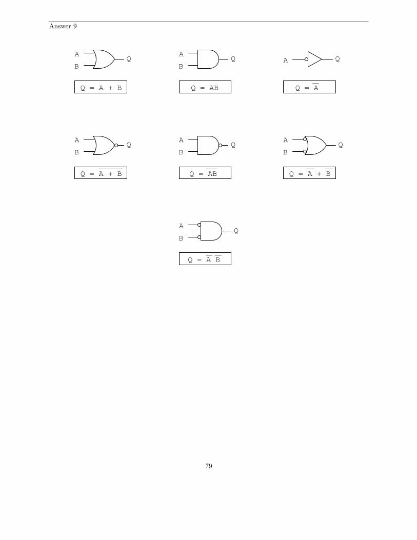
Question 9
Write the Boolean expression for each of these logic gates, showing how the output (Q) algebraicallyrelates to the inputs (A and B):
A
B
A
B
A
B
A
B
A
B
A
B
AQ Q
Q
Q Q Q
Q
Q = Q = Q =
Q = Q = Q =
Q =
file 02778
10
Question 10
Write the Boolean expression for each of these relay logic circuits, showing how the output (Q)algebraically relates to the inputs (A and B):
B Q
Q = Q = Q =
Q = Q = Q =
Q =
A QA
B
QA
B
Q
A CR1
CR1
B
Q
A CR1
CR1
B QAB
QA
file 02781
Question 11
Convert the following logic gate circuit into a Boolean expression, writing Boolean sub-expressions nextto each gate output in the diagram:
A
B
C
file 02782
11

Question 12
Convert the following logic gate circuit into a Boolean expression, writing Boolean sub-expressions nextto each gate output in the diagram:
A
B
C
D
file 01301
Question 13
Convert the following logic gate circuit into a Boolean expression, writing Boolean sub-expressions nextto each gate output in the diagram:
A
B
C
file 02783
Question 14
Convert the following relay logic circuit into a Boolean expression, writing Boolean sub-expressions nextto each relay coil and lamp in the diagram:
L1 L2
A B
C
CR1
CR1
file 02785
12

Question 15
Convert the following relay logic circuit into a Boolean expression, writing Boolean sub-expressions nextto each relay coil and lamp in the diagram:
L1 L2
A
C
CR1
CR1 B
file 02786
Question 16
Convert the following relay logic circuit into a Boolean expression, writing Boolean sub-expressions nextto each relay coil and lamp in the diagram:
L1 L2
A B
C
CR1
CR1
D
CR1
file 01302
Question 17
An automotive engineer wants to design a logic circuit that prohibits the engine in a car from beingstarted unless the driver is pressing the clutch pedal while turning the ignition switch to the ”start” position.The purpose of this feature will be to prevent the car from moving forward while being started if ever thetransmission is accidently left in gear.
Suppose we designate the status of the ignition switch ”start” position with the Boolean variable S (1 =start; 0 = run or off), and the clutch pedal position with the Boolean variable C (1 = clutch pedal depressed;0 = clutch pedal in normal, unpressed position). Write a Boolean expression for the starter solenoid status,given the start switch (S) and clutch (C) statuses. Then, draw a logic gate circuit to implement this Booleanfunction.
file 02796
13

Question 18
An engineer hands you a piece of paper with the following Boolean expression on it, and tells you tobuild a gate circuit to perform that function:
AB + C(A + B)
Draw a logic gate circuit for this function.file 01308
14
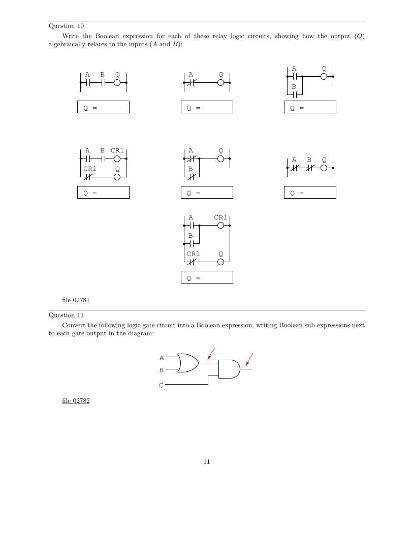
Question 19
A critical electronic system receives DC power from three power supplies, each one feeding through adiode, so that if one power supply develops an internal short-circuit, it will not cause the others to overload:
Criticalelectronicsystem
The only problem with this system is that we have no indication of trouble if just one or two powersupplies do fail. Since the diode system routes power from any available supply(ies) to the critical system,the system sees no interruption in power if one or even two of the power supplies stop outputting voltage. Itwould be nice if we had some sort of alarm system installed to alert the technicians of a problem with anyof the power supplies, long before the critical system was in jeopardy of losing power completely.
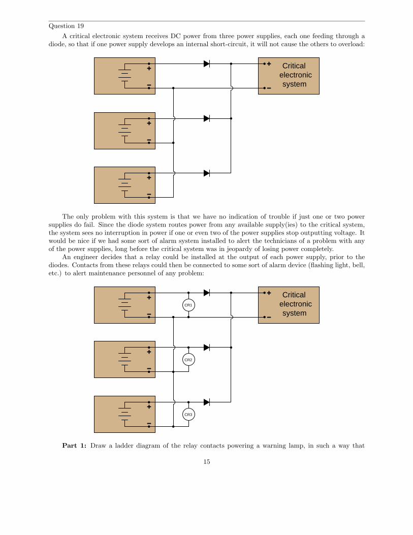
An engineer decides that a relay could be installed at the output of each power supply, prior to thediodes. Contacts from these relays could then be connected to some sort of alarm device (flashing light, bell,etc.) to alert maintenance personnel of any problem:
Criticalelectronicsystem
CR1
CR2
CR3
Part 1: Draw a ladder diagram of the relay contacts powering a warning lamp, in such a way that
15
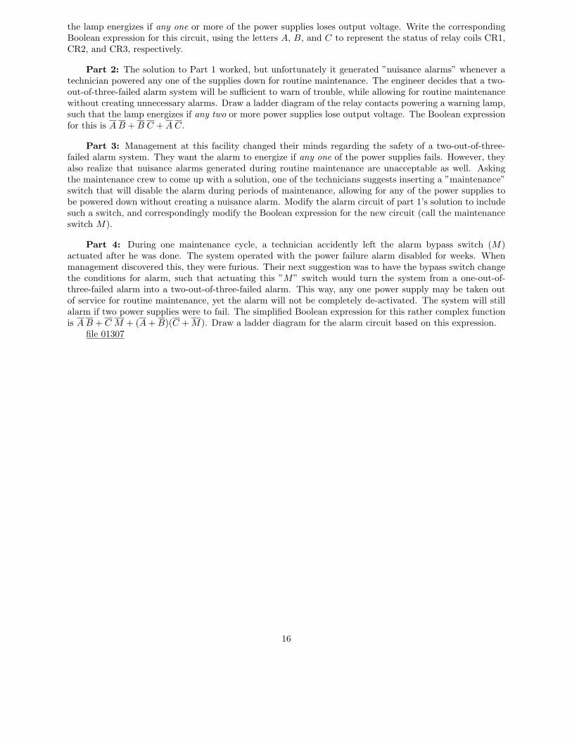
the lamp energizes if any one or more of the power supplies loses output voltage. Write the correspondingBoolean expression for this circuit, using the letters A, B, and C to represent the status of relay coils CR1,CR2, and CR3, respectively.
Part 2: The solution to Part 1 worked, but unfortunately it generated ”nuisance alarms” whenever atechnician powered any one of the supplies down for routine maintenance. The engineer decides that a two-out-of-three-failed alarm system will be sufficient to warn of trouble, while allowing for routine maintenancewithout creating unnecessary alarms. Draw a ladder diagram of the relay contacts powering a warning lamp,such that the lamp energizes if any two or more power supplies lose output voltage. The Boolean expressionfor this is A B + B C + A C.
Part 3: Management at this facility changed their minds regarding the safety of a two-out-of-three-failed alarm system. They want the alarm to energize if any one of the power supplies fails. However, theyalso realize that nuisance alarms generated during routine maintenance are unacceptable as well. Askingthe maintenance crew to come up with a solution, one of the technicians suggests inserting a ”maintenance”switch that will disable the alarm during periods of maintenance, allowing for any of the power supplies tobe powered down without creating a nuisance alarm. Modify the alarm circuit of part 1’s solution to includesuch a switch, and correspondingly modify the Boolean expression for the new circuit (call the maintenanceswitch M).
Part 4: During one maintenance cycle, a technician accidently left the alarm bypass switch (M)actuated after he was done. The system operated with the power failure alarm disabled for weeks. Whenmanagement discovered this, they were furious. Their next suggestion was to have the bypass switch changethe conditions for alarm, such that actuating this ”M” switch would turn the system from a one-out-of-three-failed alarm into a two-out-of-three-failed alarm. This way, any one power supply may be taken outof service for routine maintenance, yet the alarm will not be completely de-activated. The system will stillalarm if two power supplies were to fail. The simplified Boolean expression for this rather complex functionis A B + C M + (A + B)(C + M). Draw a ladder diagram for the alarm circuit based on this expression.
file 01307
16

Question 20
Implement the following Boolean expression in the form of a digital logic circuit:
(AB + C)B
Form the circuit by making the necessary connections between pins of these integrated circuits on asolderless breadboard:
74LS37To regulatedpower supply
A B C
74LS32
file 01309
Question 21
Complete the truth tables for these two Boolean expressions:
Output = A + B
A B Output0 00 11 01 1
Output = A + AB
A B Output0 00 11 01 1
file 02820
17

Question 22
Complete the truth tables for these two Boolean expressions:
Output = A + B + C
A B C Output0 0 00 0 10 1 00 1 11 0 01 0 11 1 01 1 1
Output = A(B + AC + A)
A B C Output0 0 00 0 10 1 00 1 11 0 01 0 11 1 01 1 1
file 02821
18

Question 23
Like real-number algebra, Boolean algebra is subject to the laws of commutation, association, anddistribution. These laws allow us to build different logic circuits that perform the same logic function.
For each of the equivalent circuit pairs shown, write the corresponding Boolean law next to it:
A
B
C
A
B
C
A B AB
A
B
C
A
B
C
A
B
C
A B A B
C C B
A
B
C
A
B A
B
Note: the three short, parallel lines represent ”equivalent to” in mathematics.file 01303
19

Question 24
Like real-number algebra, Boolean algebra is subject to certain rules which may be applied in the taskof simplifying (reducing) expressions. By being able to algebraically reduce Boolean expressions, it allowsus to build equivalent logic circuits using fewer components.
For each of the equivalent circuit pairs shown, write the corresponding Boolean rule next to it:
A
A A
A
A
+V+V
A
A A
A
A+V
A
AA
AA
CR1
CR1
20

AA
A B
A A
A B B
A
+V
Note: the three short, parallel lines represent ”equivalent to” in mathematics.file 01306
21

Question 25
Shown here are six rules of Boolean algebra (these are not the only rules, of course).
• A + A = 1• A + A = A
• A + 1 = 1• AA = A
• A + AB = A
• A + AB = A + B
Determine which rule (or rules) are being used in the following Boolean reductions:
DF + DFC = DF
1 + G = 1
B + AB = B
FE + FE = FE
XY Z + XY Z = 1
GQ + Q = Q
H H = H
CD + CD = CD
EF (EF ) = EF
CD + C = C + D
LNM + ML = LM
AGFC + FC G = FC G
M + 1 = 1
BC + BC = 1
ABC + CAB = BCA
S + STV Q = S
DE(R + 1) = DE
22

RS SR = RS
ABCD + D = D + ABC
ACB + CADB = ABC
A + T + W + A + X = 1
XY Z + X = X + Y Z
GFH HGF = FHG
CAB + AB = AB + C
file 01305
Question 26
Shown here are eight rules of Boolean algebra (these are not the only rules, of course).
• A + A = 1• A + A = A
• A + 1 = 1• AA = A
• A A = 0• A(B + C) = AB + AC
• A + AB = A
• A + AB = A + B
Determine which rule is being used in each step of the following Boolean simplification:
AB + B(B + C) + BC
AB + BB + BC + BC
AB + B + BC + BC
AB + B + BC
AB + B + C
B + C
file 02805
23

Question 27
A student makes a mistake somewhere in the process of simplifying the following Boolean expression:
AB + A(B + C)
AB + AB + C
AB + C
Determine where the mistake was made, and what the proper sequence of steps should be to simplifythe original expression.
file 02804
Question 28
Factoring is a powerful simplification technique in Boolean algebra, just as it is in real-number algebra.Show how you can use factoring to help simplify the following Boolean expressions:
C + CD
ABC + AB C
XY Z + XY Z + XY W
DEF + AB + DE + 0 + ABC
file 01313
24

Question 29
Shown here are nine rules of Boolean algebra (these are not the only rules, of course).
• A + A = 1
• A + A = A
• A + 1 = 1
• AA = A
• A(1) = A
• A A = 0
• A(B + C) = AB + AC
• A + AB = A
• A + AB = A + B
Determine which rule is being used in each step of the following Boolean simplification:
CF + F (A + B) + C
CF + AF + BF + C
C + F + AF + BF
C + F (1 + A + B)
C + F (1)
C + F
file 02806
Question 30
Two very important rules of simplification in Boolean algebra are as follows:
• Rule 1: A + AB = A
• Rule 2: A + AB = A + B
Not only are these two rules confusingly similar, but many students find them difficult to successfullyapply to situations where a Boolean expression uses different variables (letters), such as here:
RST + R
Here, it is the first rule that applies (A + AB = A) and not the second rule (A + AB = A + B), givinga simplification of:
R
25

Try to apply these two rules to the following Boolean expressions, identifying which rule directly applies,or if neither rule directly applies:
• FGH + G
• C + CF
• ABC + A
• RS + R
• AB + ABC
• ABC + C
• RV W + R
• X Y Z + XY
• J KLM + JK
• EHF + FE
file 02906
Question 31
Use Boolean algebra to simplify the following expression, then draw a logic gate circuit for the simplifiedexpression:
A(B + AB) + AC
file 02818
Question 32
Use Boolean algebra to simplify the following expression, then draw a logic gate circuit for the simplifiedexpression:
(A + B)(A + B)
file 02819
Question 33
Use Boolean algebra to simplify the following expression, then draw a logic gate circuit for the simplifiedexpression:
A B C + A B C + A B C + A B C
file 02801
Question 34
Use Boolean algebra to simplify the following logic gate circuit:
B
AOutput
file 02800
26

Question 35
Use Boolean algebra to simplify the following logic gate circuit:
OutputA
B
C
file 02797
Question 36
Use Boolean algebra to simplify the following logic gate circuit:
C
B
A
Output
file 02799
Question 37
Use Boolean algebra to simplify the following relay (ladder logic) circuit:
A
B
L1 L2
A B
file 02812
27

Question 38
Use Boolean algebra to simplify the following relay (ladder logic) circuit:
L1 L2
B
A C
A
file 02813
Question 39
Use Boolean algebra to simplify the following relay (ladder logic) circuit:
L1 L2
CA B
A C
B
file 02814
28

Question 40
Use Boolean algebra to simplify the following relay (ladder logic) circuit:
L1 L2
A B
A
B
B
A
file 02815
29

Question 41
Identify each of these logic gates by name, and complete their respective truth tables:
A B Output
00
0 1
01
1 1
A
BOutput
A B Output
00
0 1
01
1 1
A
BOutput
A B Output
00
0 1
01
1 1
A
BOutput
A B Output
00
0 1
01
1 1
A
BOutput
A B Output
00
0 1
01
1 1
A
BOutput
A B Output
00
0 1
01
1 1
A
BOutput
A B Output
00
0 1
01
1 1
A
BOutput
A B Output
00
0 1
01
1 1
A
BOutput A Output
A Output
0
1
file 01249
30

Question 42
Identify each of these relay logic functions by name (AND, OR, NOR, etc.) and complete their respectivetruth tables:
A B Output
00
0 1
01
1 1
A B Output
00
0 1
01
1 1
A B Output
00
0 1
01
1 1
A B Output
00
0 1
01
1 1
A B Output
00
0 1
01
1 1
A B Output
00
0 1
01
1 1
A B Output
00
0 1
01
1 1
A B Output
00
0 1
01
1 1
A Output
A
BA B
A
B
CR1
CR1
A B CR1
CR1A B
A
B
A B
A B
A B
A B
A CR1
CR1
1
0
file 01335
31

Question 43
Inspect each of these Boolean expressions, and determine whether each one is a sum of products, or aproduct of sums:
(B + C + D)(A + B)
AB C + ABC
(X + Y + Z)(Y + Z)(X + Y )
M N O + MNO + MNO
(X + Y + Z)(Y + Z)
ABC + ABC
file 01324
Question 44
Sum-of-Product Boolean expressions all follow the same general form. As such, their equivalent logicgate circuits likewise follow a common form. Translate each of these SOP expressions into its equivalentlogic gate circuit:
AB + AB
AB + AB
ABC + ABC + ABC
file 01325
32

Question 45
Although it is seldom done, it is possible to express a truth table in verbal form, by describing whatconditions must be met in order to generate a ”high” output.
Take for example this simple truth table, for an inverter circuit:
A Output
0
1
A Output
1
0
For this truth table, we could say that the output goes high when A is low. A different way of sayingthis would be to state that ”the output is true when A is true.”
Let’s look at another example, this time of an AND gate:
AOutput
A B Output
00
0 1
01
1 1
B
0
1
0
0
For this truth table, we could say that the output goes high when A and B are both high. A differentway of saying this would be to state that ”the output is true when A is true and B is true.” To use ahalf-Boolean, half-verbal description:
A AND B
Examine this logic gate circuit and corresponding truth table:
33

A
Output
A B Output
00
0 1
01
1 1
B
1
0
0
1
A
B
Express the functionality of this truth table in words. What Boolean conditions must be satisfied(”true”) in order for the output to assume a high state?
file 01326
Question 46
Develop a verbal description of this truth table, specifying what conditions must be met (”true” in aBoolean sense) in order for the output to assume a high state:
A B C Output0 0 0 00 0 1 00 1 0 00 1 1 01 0 0 01 0 1 11 1 0 01 1 1 0
Do the same for this truth table as well:
A B C Output0 0 0 00 0 1 10 1 0 10 1 1 01 0 0 01 0 1 01 1 0 01 1 1 0
file 01327
34

Question 47
Suppose you were faced with the task of writing a Boolean expression for a logic circuit, the internals ofwhich are unknown to you. The circuit has four inputs – each one set by the position of its own micro-switch– and one output. By experimenting with all the possible input switch combinations, and using a logic probeto ”read” the output state (at test point TP1), you were able to write the following truth table describingthe circuit’s behavior:
+ -
Mysterycircuit
SW1SW2SW3SW4
SW1 SW2 SW3 SW4
TP1
0 0 0 00 0 0 1
TP1
00000011111111
00
1111
11110000
11
11
11
11
00
00
00
01010101010101
100
00
00
00
00
00
00
0
Based on this truth table ”description” of the circuit, write an appropriate Boolean expression for thiscircuit.
file 01304
Question 48
Write a Boolean SOP expression for this truth table, then simplify that expression as much as possible,and draw a logic gate circuit equivalent to that simplified expression:
A B C Output0 0 0 00 0 1 00 1 0 10 1 1 01 0 0 01 0 1 01 1 0 11 1 1 0
file 02822
35

Question 49
Write an SOP expression for this truth table, and then draw a gate circuit diagram corresponding tothat SOP expression:
A B C Output0 0 0 00 0 1 00 1 0 10 1 1 11 0 0 01 0 1 01 1 0 01 1 1 1
Finally, simplify this expression using Boolean algebra, and draw a simplified gate circuit based on thisnew (reduced) Boolean expression.
file 01333
Question 50
Write an SOP expression for this truth table, and then draw a ladder logic (relay) circuit diagramcorresponding to that SOP expression:
BA C Output
000
100
0 1 0
10 1
01 0
101
1 1 0
11 1
0
1
0
0
0
0
1
1
L1 L2A
B
C
CR1
CR2
CR3
Implement the SOP logic function using contacts of relays CR1, CR2, and CR3. A partial ladder logicdiagram has been provided for you.
Finally, simplify this expression using Boolean algebra, and draw a simplified ladder logic diagram basedon this new (reduced) Boolean expression. When deciding ”how far” to reduce the Boolean expression, choosea form that results in the minimum number of relay contacts in the simplified ladder logic diagram.
file 01334
36

Question 51
Design the simplest relay circuit possible (i.e. having the fewest contacts) to implement the followingtruth table:
A B C Output0 0 0 00 0 1 00 1 0 10 1 1 01 0 0 01 0 1 01 1 0 11 1 1 1
file 02827
Question 52
Product-of-Sum Boolean expressions all follow the same general form. As such, their equivalent logicgate circuits likewise follow a common form. Translate each of these POS expressions into its equivalentlogic gate circuit:
(A + B)(A + B)
(A + B)(A + B)
(A + B + C)(A + B + C)(A + B + C)
file 02825
Question 53
Product-of-Sum Boolean expressions all follow the same general form. As such, their equivalent logicgate circuits likewise follow a common form. Translate each of these POS expressions into its equivalentlogic gate circuit:
(A + B)(A + B)
(A + B)(A + B)
(A + B + C)(A + B + C)(A + B + C)
file 01336
37

Question 54
In an SOP expression, the minimum requirement for the expression’s total value to be equal to 1 is thatat least one of the product terms must be equal to 1. For instance, in the following SOP expression, weknow that the value will be equal to 1 if ABC = 1 or if AB C = 1 or if ABC = 1:
ABC + AB C + ABC
What is the minimum requirement for a POS expression to be equal to 0? Take the following POSexpression, for instance:
(A + B + C)(A + B + C)(A + B + C)
At the very least, what has to occur in order for this expression to equal 0?file 01337
38

Question 55
Examine the following truth table:
A B Output
00
0 1
01
1 1 0
1
1
1
We know that this table represents the function of a NAND gate. But suppose we wished to generatea Boolean expression for this gate as though we didn’t know what it already was, and we chose to generatean SOP expression based on all the ”high” output conditions in the truth table:
A B + AB + AB
Seems like a lot of work for just one gate, doesn’t it? The fact that this truth table’s output is mostly 1’scauses us to have to write a relatively lengthy SOP expression. Wouldn’t it be easier if we had a techniqueto generate a Boolean expression from the single zero output condition in this table? If we had such atechnique, our resulting Boolean expression would have a lot fewer terms in it!
We know that a Negative-OR gate has the exact same functionality as a NAND gate. We also know thata Negative-OR gate’s Boolean representation is A + B. If there is such a thing as a technique for derivingBoolean expressions from the ”0” outputs of a truth table, this instance ought to fit it!
Now, examine the following truth table and logic gate circuit:
A B Output
00
0 1
01
1 1 0
1
1
0
A
BOutput
Derive a Boolean expression from the gate circuit shown here, and then compare that expression withthe truth table shown for this circuit. Do you see a pattern that would suggest a rule for deriving a Booleanexpression directly from the truth table in this example (and the previous example)?
Hint: the rule involves Product-of-Sums form.file 01338
39

Question 56
Examine this truth table and then write both SOP and POS Boolean expressions describing the Output:
A B C Output0 0 0 10 0 1 00 1 0 10 1 1 01 0 0 01 0 1 11 1 0 11 1 1 0
Which of those Boolean expressions is simpler for this particular truth table? Which will be easier toreduce to simplest form (for the purpose of creating a gate circuit to implement it)?
file 02823
Question 57
Write a POS expression for this truth table, and then draw a ladder logic circuit corresponding to thatexpression:
A B C Output0 0 0 10 0 1 10 1 0 10 1 1 11 0 0 11 0 1 01 1 0 11 1 1 1
file 01340
Question 58
Write a Boolean expression for this truth table, then simplify that expression as much as possible, anddraw a logic gate circuit equivalent to that simplified expression:
A B C Output0 0 0 10 0 1 10 1 0 00 1 1 11 0 0 01 0 1 11 1 0 11 1 1 1
file 01341
40

Question 59
Write a Boolean expression for this truth table, then simplify that expression as much as possible, anddraw a logic gate circuit equivalent to that simplified expression:
A B C Output0 0 0 10 0 1 10 1 0 10 1 1 11 0 0 11 0 1 11 1 0 01 1 1 0
file 02826
Question 60
Write two Boolean expressions for the Exclusive-OR function, one written in SOP form and the otherwritten in POS form. Show through Boolean algebra reduction that the two expressions are indeed equivalentto one another. Then, draw the simplest ladder logic circuit possible to implement this function.
file 01346
Question 61
A Karnaugh map is nothing more than a special form of truth table, useful for reducing logic functionsinto minimal Boolean expressions.
Here is a truth table for a specific three-input logic circuit:
B C Out0
0
0
0
1
1
1
1
0
0
1
1
0
0
1
1
0
1
0
1
0
1
0
1
1
1
0
0
0
0
1
1
A
Complete the following Karnaugh map, according to the values found in the above truth table:
AB
00
01
11
10
0 1C
file 02834
41

Question 62
A Karnaugh map is nothing more than a special form of truth table, useful for reducing logic functionsinto minimal Boolean expressions.
Here is a truth table for a specific four-input logic circuit:
A B C D Out0
0
0
0
0
0
0
0
1
1
1
1
1
1
1
1
0
0
0
0
0
0
0
0
1
1
1
1
1
1
1
1
0
0
1
1
0
0
1
1
0
0
1
1
0
0
1
1
0
1
0
1
0
1
0
1
0
1
0
1
0
1
0
1
1
1
1
1
1
1
1
0
0
0
0
0
0
0
0
0
Complete the following Karnaugh map, according to the values found in the above truth table:
ABCD
00
01
11
10
00 01 11 10
file 01310
42

Question 63
Here is a truth table for a four-input logic circuit:
A B C D Out0
0
0
0
0
0
0
0
1
1
1
1
1
1
1
1
0
0
0
0
0
0
0
0
1
1
1
1
1
1
1
1
0
0
1
1
0
0
1
1
0
0
1
1
0
0
1
1
0
1
0
1
0
1
0
1
0
1
0
1
0
1
0
1
0
1
1
1
1
0
0
0
0
0
0
0
0
0
0
0
If we translate this truth table into a Karnaugh map, we obtain the following result:
ABCD
00
01
11
10
00 01 11 10
1 1
11
0 0 0 0
0 0 0 0
0
0
0
0
Note how the only 1’s in the map are clustered together in a group of four:
ABCD
00
01
11
10
00 01 11 10
1 1
11
0 0 0 0
0 0 0 0
0
0
0
0
If you look at the input variables (A, B, C, and D), you should notice that only two of them actuallychange within this cluster of four 1’s. The other two variables hold the same value for each of these conditionswhere the output is a ”1”. Identify which variables change, and which stay the same, for this cluster.
file 01311
43
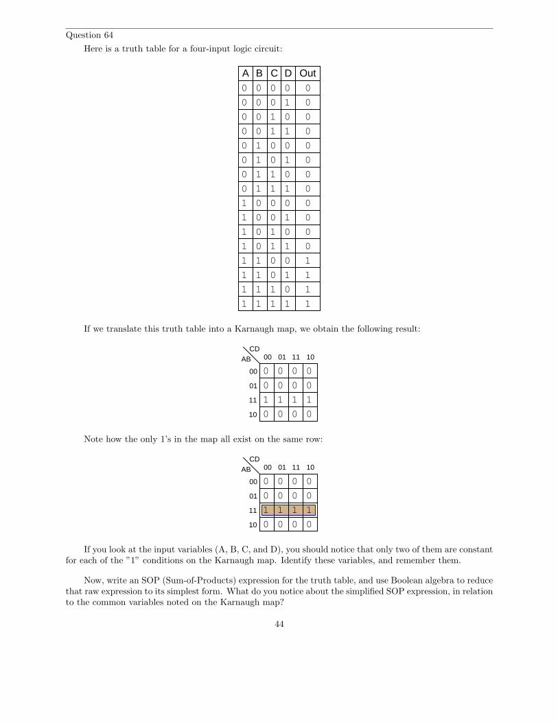
Question 64
Here is a truth table for a four-input logic circuit:
A B C D Out0
0
0
0
0
0
0
0
1
1
1
1
1
1
1
1
0
0
0
0
0
0
0
0
1
1
1
1
1
1
1
1
0
0
1
1
0
0
1
1
0
0
1
1
0
0
1
1
0
1
0
1
0
1
0
1
0
1
0
1
0
1
0
1
1
1
0
0
0
0
0
0
0
0
0
0
1
1
0
0
If we translate this truth table into a Karnaugh map, we obtain the following result:
ABCD
00
01
11
10
00 01 11 10
11
0 0 0 0
0 0 0 0
0 0
1 1
0 0
Note how the only 1’s in the map all exist on the same row:
ABCD
00
01
11
10
00 01 11 10
11
0 0 0 0
0 0 0 0
0 0
1 1
0 0
If you look at the input variables (A, B, C, and D), you should notice that only two of them are constantfor each of the ”1” conditions on the Karnaugh map. Identify these variables, and remember them.
Now, write an SOP (Sum-of-Products) expression for the truth table, and use Boolean algebra to reducethat raw expression to its simplest form. What do you notice about the simplified SOP expression, in relationto the common variables noted on the Karnaugh map?
44

file 02835
Question 65
One of the essential characteristics of Karnaugh maps is that the input variable sequences are alwaysarranged in Gray code sequence. That is, you never see a Karnaugh map with the input combinationsarranged in binary order:
ABCD
00
01
11
10
00 01 11 10 ABCD
00
01
11
10
00 01 1110
Proper form Improper form
The reason for this is apparent when we consider the use of Karnaugh maps to detect common variablesin output sets. For instance, here we have a Karnaugh map with a cluster of four 1’s at the center:
ABCD
00
01
11
10
00 01 11 10
1 1
11
0 0 0 0
0 0 0 0
0
0
0
0
Arranged in this order, it is apparent that two of the input variables have the same values for each ofthe four ”high” output conditions. Re-draw this Karnaugh map with the input variables sequenced in binaryorder, and comment on what happens. Can you still tell which input variables remain the same for all fouroutput conditions?
ABCD
00
01
11
10
00 01 1110
file 01312
45

Question 66
Examine this truth table and corresponding Karnaugh map:
A B C D Out0
0
0
0
0
0
0
0
1
1
1
1
1
1
1
1
0
0
0
0
0
0
0
0
1
1
1
1
1
1
1
1
0
0
1
1
0
0
1
1
0
0
1
1
0
0
1
1
0
1
0
1
0
1
0
1
0
1
0
1
0
1
0
1
1
1
1
1
0
0
0
0
0
0
0
0
0
ABCD
00
01
11
10
00 01 11 10
1 1
11
0
0 0
0
0
0 0
0
0
0
0
0
0
0
0
Though it may not be obvious from first appearances, the four ”high” conditions in the Karnaugh mapactually belong to the same group. To make this more apparent, I will draw a new (oversized) Karnaughmap template, with the Gray code sequences repeated twice along each axis:
ABCD
00
01
11
10
00 01 11 10 00 01 11 10
00
01
11
10
Fill in this map with the 0 and 1 values from the truth table, and then see if a grouping of four ”high”conditions becomes apparent.
file 01342
46

Question 67
A student is asked to use Karnaugh mapping to generate a minimal SOP expression for the followingtruth table:
A B C Output0 0 0 00 0 1 00 1 0 00 1 1 11 0 0 01 0 1 11 1 0 01 1 1 1
Following the truth table shown, the student plots this Karnaugh map:
AB
00
01
11
10
0 1C
0
1
1
1
0
0
0
0
”This is easy,” says the student to himself. ”All the ’1’ conditions fall within the same group!” Thestudent then highlights a triplet of 1’s as a single group:
AB
00
01
11
10
0 1C
0
1
1
1
0
0
0
0
Looking at this cluster of 1’s, the student identifies C as remaining constant (1) for all three conditionsin the group. Therefore, the student concludes, the minimal expression for this truth table must simply beC.
However, a second student decides to use Boolean algebra on this problem instead of Karnaugh mapping.Beginning with the original truth table and generating a Sum-of-Products (SOP) expression for it, thesimplification goes as follows:
ABC + ABC + ABC
BC(A + A) + ABC
BC + ABC
C(B + AB)
C(B + A)
47

AC + BC
Obviously, the answer given by the second student’s Boolean reduction (AC + BC) does not match theanswer given by the first student’s Karnaugh map analysis (C).
Perplexed by the disagreement between these two methods, and failing to see a mistake in the Booleanalgebra used by the second student, the first student decides to check his Karnaugh mapping again. Uponreflection, it becomes apparent that if the answer really were C, the Karnaugh map would look different.Instead of having three cells with 1’s in them, there would be four cells with 1’s in them (the output of thefunction being ”1” any time C = 1:
AB
00
01
11
10
0 1C
0
1
1
1
0
0
0
1
Somewhere, there must have been a mistake made in the first student’s grouping of 1’s in the Karnaughmap, because the map shown above is the only one proper for an answer of C, and it is not the same as thereal map for the given truth table. Explain where the mistake was made, and what the proper grouping of1’s should be.
file 02836
Question 68
State the rules for properly identifying common groups in a Karnaugh map.file 02837
48

Question 69
A seven segment decoder is a digital circuit designed to drive a very common type of digital displaydevice: a set of LED (or LCD) segments that render numerals 0 through 9 at the command of a four-bitcode:
Seven-segment display
a
b
cd
e
fg
ABCD
abcdefg
Display driver IC
VDD
. . .
. . .
. . .
. . .
. . .
. . .
. . .
Inputs
The behavior of the display driver IC may be represented by a truth table with seven outputs: one foreach segment of the seven-segment display (a through g). In the following table, a ”1” output represents anactive display segment, while a ”0” output represents an inactive segment:
D C B A a b c d e f g Display0 0 0 0 1 1 1 1 1 1 0 ”0”0 0 0 1 0 1 1 0 0 0 0 ”1”0 0 1 0 1 1 0 1 1 0 1 ”2”0 0 1 1 1 1 1 1 0 0 1 ”3”0 1 0 0 0 1 1 0 0 1 1 ”4”0 1 0 1 1 0 1 1 0 1 1 ”5”0 1 1 0 1 0 1 1 1 1 1 ”6”0 1 1 1 1 1 1 0 0 0 0 ”7”1 0 0 0 1 1 1 1 1 1 1 ”8”1 0 0 1 1 1 1 1 0 1 1 ”9”
A real-life example such as this provides an excellent showcase for techniques such as Karnaugh mapping.Let’s take output a for example, showing it without all the other outputs included in the truth table:
D C B A a0 0 0 0 10 0 0 1 00 0 1 0 10 0 1 1 10 1 0 0 00 1 0 1 10 1 1 0 10 1 1 1 11 0 0 0 11 0 0 1 1
Plotting a Karnaugh map for output a, we get this result:
49

00
01
11
10
00 01 11 10
11
0
0
1
1
1 1 1
1
DCBA
Identify adjacent groups of 1’s in this Karnaugh map, and generate a minimal SOP expression fromthose groupings.
Note that six of the cells are blank because the truth table does not list all the possible inputcombinations with four variables (A, B, C, and D). With these large gaps in the Karnaugh map, it isdifficult to form large groupings of 1’s, and thus the resulting ”minimal” SOP expression has several terms.
However, if we do not care about output a’s state in the six non-specified truth table rows, we can fillin the remaining cells of the Karnaugh map with ”don’t care” symbols (usually the letter X) and use thosecells as ”wildcards” in determining groupings:
00
01
11
10
00 01 11 10
11
0
0
1
1
1 1 1
1
DCBA
With this new Karnaugh map, identify adjacent groups of 1’s, and generate a minimal SOP expressionfrom those groupings.
file 02838
Question 70
When designing a circuit to emulate a truth table such as this where nearly all the input conditions resultin ”1” output states, it is easier to use Product-of-Sums (POS) expressions rather than Sum-of-Products(SOP) expressions:
A B C Output0 0 0 10 0 1 10 1 0 10 1 1 11 0 0 11 0 1 11 1 0 01 1 1 0
Is it possible to use a Karnaugh map to generate the appropriate POS expression for this truth table,or are Karnaugh maps limited to SOP expressions only? Explain your answer, and how you were able toobtain it.
file 02839
50

Question 71
Use a Karnaugh map to generate a simple Boolean expression for this truth table, and draw a relaylogic circuit equivalent to that expression:
A B C Output0 0 0 00 0 1 00 1 0 10 1 1 01 0 0 01 0 1 01 1 0 11 1 1 0
file 02840
Question 72
Use a Karnaugh map to generate a simple Boolean expression for this truth table, and draw a gatecircuit equivalent to that expression:
A B C D Output0 0 0 0 00 0 0 1 00 0 1 0 00 0 1 1 00 1 0 0 00 1 0 1 00 1 1 0 10 1 1 1 01 0 0 0 01 0 0 1 01 0 1 0 11 0 1 1 11 1 0 0 01 1 0 1 01 1 1 0 11 1 1 1 1
file 02841
51

Question 73
Use a Karnaugh map to generate a simple Boolean expression for this truth table, and draw a gatecircuit equivalent to that expression:
A B C D Output0 0 0 0 00 0 0 1 00 0 1 0 00 0 1 1 00 1 0 0 00 1 0 1 00 1 1 0 00 1 1 1 01 0 0 0 11 0 0 1 01 0 1 0 11 0 1 1 11 1 0 0 01 1 0 1 01 1 1 0 11 1 1 1 1
file 02842
Question 74
Use a Karnaugh map to generate a simple Boolean expression for this truth table, and draw a relaycircuit equivalent to that expression:
A B C D Output0 0 0 0 10 0 0 1 00 0 1 0 00 0 1 1 00 1 0 0 10 1 0 1 00 1 1 0 10 1 1 1 01 0 0 0 11 0 0 1 01 0 1 0 01 0 1 1 01 1 0 0 11 1 0 1 01 1 1 0 11 1 1 1 0
file 02843
52

Question 75
Use a Karnaugh map to generate a simple Boolean expression for this truth table, and draw a relaycircuit equivalent to that expression:
A B C D Output0 0 0 0 10 0 0 1 00 0 1 0 10 0 1 1 00 1 0 0 10 1 0 1 10 1 1 0 10 1 1 1 11 0 0 0 11 0 0 1 01 0 1 0 11 0 1 1 01 1 0 0 11 1 0 1 11 1 1 0 11 1 1 1 1
file 02844
Question 76
Complete truth tables for the following gates, and also write the Boolean expression for each gate:
A B Output
00
0 1
01
1 1
A B Output
00
0 1
01
1 1
The results should be obvious once the truth tables are both complete. Is there a general principle atwork here? Do you think we would obtain similar results with Negative-OR and NAND gates? Explain.
file 01314
53

Question 77
Often, we find extended complementation ”bars” in Boolean expressions. A simple example is shownhere, where a long bar extends over the Boolean expression A + B:
A + B
In this particular case, the expression represents the functionality of a NOR gate. Many times in themanipulation of Boolean expressions, it is good to be able to know how to eliminate such long bars. Wecan’t just get rid of the bar, though. There are specific rules to follow for ”breaking” long bars into smallerbars in Boolean expressions.
What other type of logic gate has the same functionality (the same truth table) as a NOR gate, andwhat is its equivalent Boolean expression? The answer to this question will demonstrate what rule(s) weneed to follow when we ”break” a long complementation bar in a Boolean expression.
Another example we could use for learning how to ”break bars” in Boolean algebra is that of the NANDgate:
AB
What other type of logic gate has the same functionality (the same truth table) as a NAND gate, andwhat is its equivalent Boolean expression? The answer to this question will likewise demonstrate what rule(s)we need to follow when we ”break” a long complementation bar in a Boolean expression.
file 01315
Question 78
What is DeMorgan’s Theorem?file 01323
Question 79
Use DeMorgan’s Theorem, as well as any other applicable rules of Boolean algebra, to simplify thefollowing expression so there are no more complementation bars extending over multiple variables:
AB + AC
file 02828
Question 80
Use DeMorgan’s Theorem, as well as any other applicable rules of Boolean algebra, to simplify thefollowing expression so there are no more complementation bars extending over multiple variables:
XY ZY
file 02829
Question 81
Use DeMorgan’s Theorem, as well as any other applicable rules of Boolean algebra, to simplify thefollowing expression so there are no more complementation bars extending over multiple variables:
J + KJL
file 02830
54

Question 82
Use Boolean algebra to simplify the following logic gate circuit:
OutputA
B
file 02798
Question 83
Write the Boolean expression for this relay logic circuit, then reduce that expression to its simplest formusing any applicable Boolean laws and theorems. Finally, draw a new relay circuit based on the simplifiedBoolean expression that performs the exact same logic function.
L1 L2
A B CR1
CR1
C
CR2
CR2
file 01316
55

Question 84
Write the Boolean expression for this TTL logic gate circuit, then reduce that expression to its simplestform using any applicable Boolean laws and theorems. Finally, draw a new gate circuit diagram based onthe simplified Boolean expression, that performs the exact same logic function.
To regulatedpower supply
A B C
Output
74LS37 74LS32
file 01317
Question 85
A student makes a mistake somewhere in the process of simplifying the Boolean expression XY + Z.Determine what the mistake is:
XY + Z
XY Z
X + Y Z
X + Y Z
file 01319
56

Question 86
Write the Boolean expression for this TTL logic gate circuit, then reduce that expression to its simplestform using any applicable Boolean laws and theorems. Finally, draw a new gate circuit diagram based onthe simplified Boolean expression that performs the exact same logic function.
Output
A
B
C
file 01318
Question 87
Suppose you needed an inverter gate in a logic circuit, but none were available. You do, however, havea spare (unused) NAND gate in one of the integrated circuits. Show how you would connect a NAND gateto function as an inverter.
Use Boolean algebra to show that your solution is valid.file 01320
Question 88
Suppose you needed an inverter gate in a logic circuit, but none were available. You do, however, havea spare (unused) NOR gate in one of the integrated circuits. Show how you would connect a NOR gate tofunction as an inverter.
Use Boolean algebra to show that your solution is valid.file 01321
57

Question 89
The equivalence between NAND gates and Negative-OR gates is something easily verified by anexamination of these two gates’ respective truth tables, and is often a starting-point for learning aboutDeMorgan’s Theorem:
A
BAB
A
BA + B
A lesser-known fact is how the equivalence between NAND and Negative-OR gates may be transformedto express an equivalence between two other types of gates, shown here:
A
BAB
A
BA + B
Another example is shown here:
A
B
A
BA + BA B
Explain how the first equivalence (between the NAND and the Negative-OR gate) was transformed intothe latter two equivalences, both in terms of the gate symbols and their respective Boolean expressions. Inother words, explain how we can derive the last two examples by manipulating the first example.
file 03982
Question 90
Suppose we wished to have an AND gate for some logic purpose, but did not have any AND gates onhand. Instead, we only had NOR gates in our parts collection. Draw a diagram whereby multiple NORgates are connected together to form an AND gate.
file 03983
58

Question 91
NAND and NOR gates both have the interesting property of universality. That is, it is possible tocreate any logic function at all, using nothing but multiple gates of either type. The key to doing this isDeMorgan’s Theorem, because it shows us how properly applied inversion is able to convert between the twofundamental logic gate types (from AND to OR, and visa-versa).
Using this principle, convert the following gate circuit diagram into one built exclusively of NAND gates(no Boolean simplification, please). Then, do the same using nothing but NOR gates:
A
B
C
file 01322
Question 92
An Exclusive-OR gate has the following Boolean expression:
AB + AB
Draw the schematic diagram for a gate circuit exhibiting this Boolean function, constructed entirelyfrom NAND gates.
file 02816
Question 93
An automobile manufacturer needs a logic circuit to perform a specific task in its new line of cars. Thesecars will be equipped with a ”headlight left on” alarm that sounds any time these two conditions are met:headlights on and ignition switch off. Draw the schematic diagram of a logic gate circuit that will implementthis alarm, constructed entirely out of NAND gates.
file 02831
59

Question 94
Draw a schematic for a logic gate circuit using nothing but two-input NOR gates that mimics theoperation of this relay circuit:
L1 L2
A
B
CR1
CR1 C CR2
CR2
file 02833
Question 95
Shown here is the ladder logic diagram for a fire alarm system, where the activation of any alarm switchopens that (normally-closed) switch contact and sounds the alarm:
L1 L2
SwitchA
Switch Switch Switch SwitchB C D E CR1
CR1 Alarm solenoid
Write the Boolean expression for this relay circuit, then simplify that expression using DeMorgan’sTheorem and draw a new relay circuit implementing the simplified expression.
file 02832
60

Question 96
Version:
Schematic
A
B
VDD VDD
Rpullup
Competency: Gate circuit from Boolean expression
Boolean expression
Output =
Truth table
Predicted Actual
A B Output
00
0 1
01
1 1
A B Output
00
0 1
01
1 1
Rlimit
file 02809
61

Question 97
Version:
Schematic
Truth table
BA C Output
000
100
0 1 0
10 1
01 0
101
1 1 0
11 1
A
B
C
VDD VDD VDD
Rpullup
Competency: Gate circuit from truth table
Rlimit
Given
BA C Output
000
100
0 1 0
10 1
01 0
101
1 1 0
11 1
Actual
file 02134
62

Question 98
Version:
Truth table
A
B
Predicted Actual
VDD VDD
Rpullup
Rlimit
Diagram
A B Output
00
0 1
01
1 1
A B Output
00
0 1
01
1 1
Description
Competency: NAND gate universality
Emulated function
AND OR NOR
(instructor checks one box)
Emulate the specified logic function usingnothing but interconnected NAND gates.
file 02807
63

Question 99
NAME: Project Grading Criteria PROJECT:You will receive the highest score for which all criteria are met.
100 % (Must meet or exceed all criteria listed)A. Impeccable craftsmanship, comparable to that of a professional assemblyB. No spelling or grammatical errors anywhere in any document, upon first submission to instructor
95 % (Must meet or exceed these criteria in addition to all criteria for 90% and below)A. Technical explanation sufficiently detailed to teach from, inclusive of every component (supersedes 75.B)B. Itemized parts list complete with part numbers, manufacturers, and (equivalent) prices for all
components, including recycled components and parts kit components (supersedes 90.A)
90 % (Must meet or exceed these criteria in addition to all criteria for 85% and below)A. Itemized parts list complete with prices of components purchased for the project, plus total priceB. No spelling or grammatical errors anywhere in any document upon final submission
85 % (Must meet or exceed these criteria in addition to all criteria for 80% and below)A. “User’s guide” to project function (in addition to 75.B)B. Troubleshooting log describing all obstacles overcome during development and construction
80 % (Must meet or exceed these criteria in addition to all criteria for 75% and below)A. All controls (switches, knobs, etc.) clearly and neatly labeledB. All documentation created on computer, not hand-written (including the schematic diagram)
75 % (Must meet or exceed these criteria in addition to all criteria for 70% and below)A. Stranded wire used wherever wires are subject to vibration or bendingB. Basic technical explanation of all major circuit sectionsC. Deadline met for working prototype of circuit (Date/Time = / )
70 % (Must meet or exceed these criteria in addition to all criteria for 65%)A. All wire connections sound (solder joints, wire-wrap, terminal strips, and lugs are all connected properly)B. No use of glue where a fastener would be more appropriateC. Deadline met for submission of fully-functional project (Date/Time = / ) –
supersedes 75.C if final project submitted by that (earlier) deadline
65 % (Must meet or exceed these criteria in addition to all criteria for 60%)A. Project fully functionalB. All components securely fastened so nothing is “loose” inside the enclosureC. Schematic diagram of circuit
60 % (Must meet or exceed these criteria in addition to being safe and legal)A. Project minimally functional, with all components located inside an enclosure (if applicable)B. Passes final safety inspection (proper case grounding, line power fusing, power cords strain-relieved)
0 % (If any of the following conditions are true)A. Fails final safety inspection (improper grounding, fusing, and/or power cord strain relieving)B. Intended project function poses a safety hazardC. Project function violates any law, ordinance, or school policy
file 03173
64

Question 100
One way to think of logic gate types is to consider what input states guarantee a certain output state.For example, we could describe the function of an AND gate as such:
Any low input guarantees a low output.
Identify what type of gate is represented by each of the following phrases:
• Any low input guarantees a high output.• Any high input guarantees a low output.• Any high input guarantees a high output.• Any difference in the inputs guarantees a high output.• Any difference in the inputs guarantees a low output.
Also, explain how this sort of gate identification could be useful in troubleshooting logic gate circuits.file 03833
Question 101
A different way to view the functions of two-input logic gates is to think of them in terms of signalcontrollers, where the status of one input affects how the other input’s signal passes through to the output.The generic schematic diagram for this format is as such:
VDD
Control
AB
In1
In2
Out
Logic gate
Identify the types of logic gates which do the following (there is more than one type of gate for each ofthe following rules!):
• B = A when Control is high• B = A when Control is low• B = A when Control is high• B = A when Control is low
Also, explain how an understanding of this can be helpful in troubleshooting faulted logic gates.file 03834
65

Question 102
Predict how the operation of this logic gate circuit will be affected as a result of the following faults.Consider each fault independently (i.e. one at a time, no multiple faults):
A
B
C
D
U1U2
U3
U4
• Output of OR gate U2 fails low:
• Output of inverter gate U3 fails low:
• Output of AND gate U1 fails high:
For each of these conditions, explain why the resulting effects will occur.file 03831
Question 103
Predict how the operation of this logic gate circuit will be affected as a result of the following faults.Consider each fault independently (i.e. one at a time, no multiple faults):
A
B
C
U1
U2U3
• Output of AND gate U2 fails low:
• Output of AND gate U2 fails high:
• Output of inverter gate U1 fails low:
For each of these conditions, explain why the resulting effects will occur.file 03832
66

Question 104
Predict how the operation of this logic gate circuit will be affected as a result of the following faults.Consider each fault independently (i.e. one at a time, no multiple faults):
A
B
C
D
U1U2
U3
U4
• Output of NAND gate U2 fails low:
• Output of buffer gate U3 fails low:
• Output of NOR gate U1 fails high:
For each of these conditions, explain why the resulting effects will occur.file 03835
67

Question 105
Predict how the operation of this relay logic circuit will be affected as a result of the following faults.Consider each fault independently (i.e. one at a time, no multiple faults):
L1 L2
CR1A
B CR2
CR3
Lamp 1
Lamp 2
CR1-1
CR1-2
CR2-1
CR2-2
CR3-1
• Pushbutton switch A fails open:
• Relay coil CR2 fails open:
• Relay contact CR1-1 fails open:
• Relay contact CR2-1 fails shorted:
• Relay contact CR2-2 fails shorted:
For each of these conditions, explain why the resulting effects will occur.file 03836
68

Question 106
This circuit is supposed to energize a lamp when the input voltage (Vin) falls between the two referencevoltages set by Rpot1 and Rpot2. Predict how the operation of this circuit will be affected as a result of thefollowing faults. Consider each fault independently (i.e. one at a time, no multiple faults):
−
+
−
+
VDD
Rpot1
Rpot2
Vin
VDD
U1
U2
U3
Q1
Lamp
Vref(high)
Vref(low)
• Comparator U1 output fails low:
• Comparator U1 output fails high:
• Comparator U2 output fails low:
• Comparator U2 output fails high:
• Wire connecting VDD to Rpot1 fails open:
For each of these conditions, explain why the resulting effects will occur.file 03837
69

Question 107
This circuit is supposed to energize the green lamp when the input voltage (Vin) falls between the tworeference voltages set by Rpot1 and Rpot2, and energize the red lamp when the input voltage exceeds bothreference voltages. However, something is wrong with this circuit: the green lamp operates just as it should,but the red lamp never turns on even when it is supposed to.
−
+
−
+
VDD
Rpot1
Rpot2
Vin
VDD
U1
U2
U3
Q1
Vref(high)
Vref(low)
Lamp
Q2
VDD
U4
LampGreen
Red
A technician decides to replace the red lamp, thinking it is burned out. This, unfortunately, does notfix the problem. Identify two possible component faults that could account for this problem, and describewhat further diagnostic steps you would take to determine the precise nature of the fault.
file 03839
70

Question 108
A technician decides to check a suspect three-input AND gate using a logic pulser. She touches the logicpulser to each input of the AND gate, while looking for a pulsing signal at the output with a logic probe.
TP1
TP2
TP3
TP4
. . .
. . .
. . .
. . .
Pulser
Logi
c pr
obe
No matter which input test point (TP1, TP2, or TP3) she pulses, though, the output test point (TP4)always reads low. Does this prove the AND gate to be defective? Explain why or why not.
file 03840
Question 109
There is a problem somewhere in this relay logic circuit. Lamp 2 operates exactly as it should, but lamp1 never turns on. Identify all possible failures in the circuit that could cause this problem, and then explainhow you would troubleshoot the problem as efficiently as possible (taking the least amount of electricalmeasurements to identify the specific problem).
L1 L2
CR1A
B CR2
CR1
CR2
CR3
CR3
CR1 CR2
Lamp 1
Lamp 2
file 01296
71

Question 110
The Law of Distribution in boolean algebra is identical to the law of distribution in ”normal” algebra:
A(B + C) = AB + AC Applying the Law of Distribution
While the process of distribution is not difficult to understand, the reverse of distribution (calledfactoring) seems to be a more difficult process for many students to master:
AB + AC = A(B + C) Factoring A out of each term
Survey the following examples of factoring, and then describe what this process entails. What pattern(s)are you looking for when trying to factor a Boolean expression?
CD + AD + BD = D(C + A + B)
XY Z + X Y Z = Y (XZ + X Z)
J + JK = J(1 + K)
AB + ABCD + BCD + B = B(A + ACD + CD + 1)
file 02811
Question 111
Simplify this logic gate circuit, which uses nothing but NAND gates to accomplish a certain logicfunction:
Output
A
B
file 02802
Question 112
Simplify this logic gate circuit, which uses nothing but NOR gates to accomplish a certain logic function:
Output
A
B
file 02803
72

Question 113
Sum-of-Products (SOP) expressions may be implemented by a combination of AND and OR gates, assuch:
A
B
C
D
AB + CD
Use DeMorgan’s Theorem to prove that this NAND gate circuit performs the exact same function:
A
B
C
D
file 02860
Question 114
Write the Boolean expression for this logic gate circuit, then reduce that expression to its simplest formusing any applicable Boolean laws and theorems. Finally, draw a new gate circuit diagram based on thesimplified Boolean expression that performs the exact same logic function.
A
B
C
file 02932
Question 115
Write the Boolean expression for this logic gate circuit, then reduce that expression to its simplest formusing any applicable Boolean laws and theorems. Finally, draw a new gate circuit diagram based on thesimplified Boolean expression that performs the exact same logic function.
A
B
C
file 02933
73
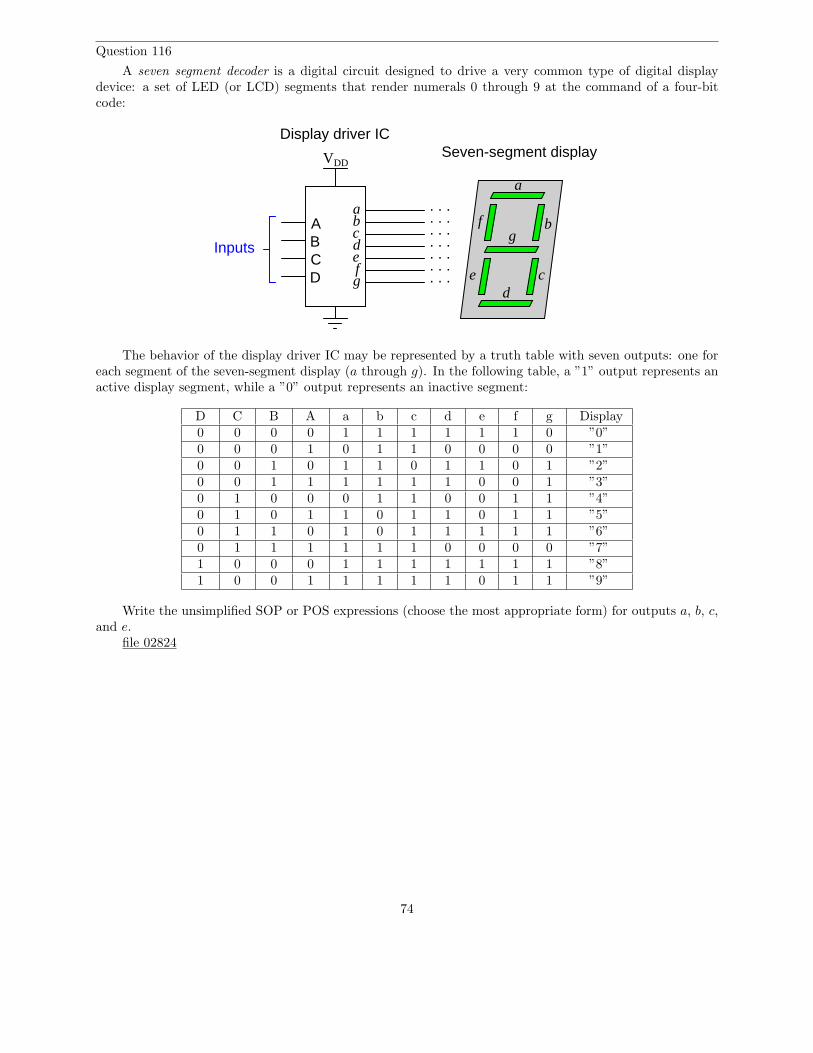
Question 116
A seven segment decoder is a digital circuit designed to drive a very common type of digital displaydevice: a set of LED (or LCD) segments that render numerals 0 through 9 at the command of a four-bitcode:
Seven-segment display
a
b
cd
e
fg
ABCD
abcdefg
Display driver IC
VDD
. . .
. . .
. . .
. . .
. . .
. . .
. . .
Inputs
The behavior of the display driver IC may be represented by a truth table with seven outputs: one foreach segment of the seven-segment display (a through g). In the following table, a ”1” output represents anactive display segment, while a ”0” output represents an inactive segment:
D C B A a b c d e f g Display0 0 0 0 1 1 1 1 1 1 0 ”0”0 0 0 1 0 1 1 0 0 0 0 ”1”0 0 1 0 1 1 0 1 1 0 1 ”2”0 0 1 1 1 1 1 1 0 0 1 ”3”0 1 0 0 0 1 1 0 0 1 1 ”4”0 1 0 1 1 0 1 1 0 1 1 ”5”0 1 1 0 1 0 1 1 1 1 1 ”6”0 1 1 1 1 1 1 0 0 0 0 ”7”1 0 0 0 1 1 1 1 1 1 1 ”8”1 0 0 1 1 1 1 1 0 1 1 ”9”
Write the unsimplified SOP or POS expressions (choose the most appropriate form) for outputs a, b, c,and e.
file 02824
74

Answers
Answer 1
A B Output
00
0 1
01
1 1
A
BOutput
A B Output
00
0 1
01
1 1
A
BOutput
A B Output
00
0 1
01
1 1
A
BOutput
A B Output
00
0 1
01
1 1
A
BOutput
A B Output
00
0 1
01
1 1
A
BOutput
A B Output
00
0 1
01
1 1
A
BOutput
A B Output
00
0 1
01
1 1
A
BOutput
A B Output
00
0 1
01
1 1
A
BOutput A Output
A Output
OR
AND
Neg-AND
NORNAND
Neg-OR XOR
XNOR NOT
0
1
1
1
0
0
0
1
0
0
0
11
1
1
0
0
0
0
1 1
1
1
0
1
1
0
0
0
0
1
1
1
01
0
75

Answer 2
A B Output
00
0 1
01
1 1
A B Output
00
0 1
01
1 1
A B Output
00
0 1
01
1 1
A B Output
00
0 1
01
1 1
A B Output
00
0 1
01
1 1
A B Output
00
0 1
01
1 1
A B Output
00
0 1
01
1 1
A B Output
00
0 1
01
1 1
A Output
A
B
A B
A
B
CR1
CR1
A B CR1
CR1
A B
A
B
A B
A B
A B
A B
A CR1
CR1
0
1
0
0
1
1
1
0
1
0
0
0
1
0
1
1
0
1
1
1
1
0
0
0
1
0
0
0
1
1
1
1
0
0
AND
OR
NOR
Neg-AND
NAND
Neg-OR
XOR
XNOR NOT
0
1
Answer 3
Boolean quantities can only have one out of two possible values: either 0 or 1. There is no such thingas ”2” – or any other digit besides 0 or 1 for that matter – in the set of Boolean numbers!
Answer 4
Boolean quantities can only have one out of two possible values: either 0 or 1. There is no such thingas ”2” in the set of Boolean numbers.
Answer 5
This set of Boolean expressions resembles the truth table for an OR logic gate circuit, suggesting thatBoolean addition may symbolize the logical OR function.
Answer 6
This set of Boolean expressions resembles the truth table for an AND logic gate circuit, suggesting thatBoolean multiplication may symbolize the logical AND function.
76

Answer 7
A Boolean ”complement” is the opposite value of a given number. This is represented either by overbarsor prime marks next to the variable (i.e. the complement of A may be written as either A or A′):
AA
001
1
A A
AA
77

Answer 8
Z = X + Y
X
YZ
Logic gate for addition
Boolean addition
Ladder logic circuit for addition
L1 L2
X
Y
Z
X
YZ
L1 L2
Z
Boolean multiplication
Logic gate for multiplication Ladder logic circuit for multiplication
Z = X Y
X Y
X Z
L1 L2
Z
Boolean inversion
Z = X
Logic gate for inversion Ladder logic circuit for inversion
X
78
Answer 9
A
B
A
B
A
B
A
B
A
B
A
B
AQ Q
Q
Q Q Q
Q
Q = ABQ = A + B Q = A
Q = A + B Q = AB Q = A + B
Q = A B
79

Answer 10
B QA QA
B
QA
B
Q
A CR1
CR1
B
Q
A CR1
CR1
B QAB
QA
Q = AB Q = A + BQ = A
Q = A + B
Q = AB Q = A + B Q = A B
Answer 11
A
B
C
A + BC(A + B)
80

Answer 12
A
B
C
D
ABAB + C
D(AB + C)
D
Answer 13
A
B
C
AAB
ABC
Answer 14
L1 L2
A B
C
CR1
CR1
AB
ABC
Answer 15
L1 L2
A
C
CR1
CR1 B
A
AB + C
81

Answer 16
L1 L2
A B
C
CR1
CR1
D
CR1
AB
ABC
AB + D
Answer 17
Boolean expression:
SC
Logic gate circuit:
To starter solenoidStart switch (S)
Clutch pedal (C) circuitry
Answer 18
A
B
C
82

Answer 19
Part 1 solution:
L1 L2
A + B + C
CR1 (A)
CR2 (B)
CR3 (C)
Part 2 solution:
L1 L2
CR1 (A)
CR2 (B)
CR3 (C)
AB + BC + AC
CR2 (B)
CR3 (C)
CR1 (A)
Part 3 solution:
CR1 (A)
CR2 (B)
CR1 (A)
M
M(A + B + C)
L1 L2
83

Part 4 solution:
L1 L2
CR1 (A)
CR3 (C)
CR2 (B)
CR3 (C)
CR1 (A)
AB + CM + (A + B)(C + M)
M
CR2 (B) M
Follow-up question: how many contacts on each relay (and on the maintenance switch ”M”) arenecessary to implement any of these alarm functions?
Challenge question: can you see any way we could reduce the number of relay contacts necessary in thecircuit of solutions 2, yet still achieve the same logic functionality (albeit with a different Boolean expression)?
Answer 20
The circuit shown is not the only possible solution to this problem:
74LS37To regulatedpower supply
A B C
74LS32
Output
84

Answer 21
Output = A + B
A B Output0 0 10 1 11 0 01 1 1
Output = A + AB
A B Output0 0 00 1 11 0 11 1 1
85

Answer 22
Output = A + B + C
A B C Output0 0 0 10 0 1 10 1 0 10 1 1 11 0 0 11 0 1 11 1 0 01 1 1 1
Output = A(B + AC + A)
A B C Output0 0 0 00 0 1 00 1 0 00 1 1 01 0 0 01 0 1 11 1 0 11 1 1 1
Answer 23
In order, from top to bottom:
AB = BA
(AB)C = A(BC)
(A + B)C = AC + BC
A + B = B + A
(A + C)B = AB + CB
(A + B) + C = A + (B + C)
86

Answer 24
In order, from top to bottom, left to right:
A + A = A
AA = A
A + 0 = A
A + 1 = 1
A = A
A × 0 = 0
A × 1 = A
AA = 0
A + A = 1
A + AB = A
A + AB = A + B
87

Answer 25
DF + DFC = DF Rule: A + AB = A
1 + G = 1 Rule: A + 1 = 1
B + AB = B Rule: A + AB = A
FE + FE = FE Rule: A + A = A
XY Z + XY Z = 1 Rule: A + A = 1
GQ + Q = Q Rule: A + AB = A
H H = H Rule: AA = A
CD + CD = CD Rule: A + A = A
EF (EF ) = EF Rule: AA = A
CD + C = C + D Rule: A + AB = A + B
LNM + ML = LM Rule: A + AB = A
AGFC + FC G = FC G Rule: A + AB = A
M + 1 = 1 Rule: A + 1 = 1
BC + BC = 1 Rule: A + A = 1
ABC + CAB = BCA Rule: A + A = A
S + STV Q = S Rule: A + AB = A
DE(R + 1) = DE Rule: A + 1 = 1
RS SR = RS Rule: AA = A
ABCD + D = D + ABC Rule: A + AB = A + B
ACB + CADB = ABC Rule: A + AB = A
88

A + T + W + A + X = 1 Rule: A + A = 1 Rule: A + 1 = 1
XY Z + X = X + Y Z Rule: A + AB = A + B
GFH HGF = FHG Rule: AA = A
CAB + AB = AB + C Rule: A + AB = A + B
Answer 26
AB + B(B + C) + BC
Rule: A(B + C) = AB + AC
AB + BB + BC + BC
Rule: AA = A
AB + B + BC + BC
Rule: A + AB = A
AB + B + BC
Rule: A + AB = A + B
AB + B + C
Rule: A + AB = A
B + C
89

Answer 27
An error was made in the second step (distribution). The correct sequence of steps is as follows:
AB + A(B + C)
AB + AB + AC
AB + AC
A(B + C)
Answer 28
You will be expected to show your work (including all factoring) in your answers!
C + CD = C
ABC + AB C = AB
XY Z + XY Z + XY W = XY
DEF + AB + DE + 0 + ABC = AB + DE
90

Answer 29
CF + F (A + B) + C
Rule: A(B + C) = AB + AC
CF + AF + BF + C
Rule: A + AB = A + B
C + F + AF + BF
(Factoring)
C + F (1 + A + B)
Rule: A + 1 = 1
C + F (1)
Rule: A(1) = A
C + F
Answer 30
• FGH + G = G (Rule 1)
• C + CF = C + F (Rule 2)
• ABC + A (Neither rule applies)
• RS + R = R + S (Rule 2)
• AB + ABC = AB + C (Rule 2)
• ABC + C = C (Rule 1)
• RV W + R = R (Rule 1)
• X Y Z + XY (Neither rule applies)
• J KLM + JK (Neither rule applies)
• EHF + FE = EF (Rule 1)
91

Answer 31
A
B
C
Answer 32
A
B
Challenge question: identify the specific logic gate type that will perform this Boolean function usingjust a single gate.
Answer 33
B Output
Answer 34
B
AOutput
Answer 35
OutputA
B
C
Answer 36
C
B
A
Output
92

Answer 37
L1 L2
BA
Answer 38
L1 L2
C
A
B
Answer 39
L1 L2
A C
B
Answer 40
L1 L2
A B
93

Answer 41
A B Output
00
0 1
01
1 1
A
BOutput
A B Output
00
0 1
01
1 1
A
BOutput
A B Output
00
0 1
01
1 1
A
BOutput
A B Output
00
0 1
01
1 1
A
BOutput
A B Output
00
0 1
01
1 1
A
BOutput
A B Output
00
0 1
01
1 1
A
BOutput
A B Output
00
0 1
01
1 1
A
BOutput
A B Output
00
0 1
01
1 1
A
BOutput A Output
A Output
OR AND Neg-AND
NOR NAND Neg-OR
XOR XNOR NOT
0
1
1
1
0
0
0
1
0
0
0
1 1
1
1
0
0
0
0
1
1
1
1
0
1
1
0
0
0
0
1
1
1
0
0
1
94

Answer 42
A B Output
00
0 1
01
1 1
A B Output
00
0 1
01
1 1
A B Output
00
0 1
01
1 1
A B Output
00
0 1
01
1 1
A B Output
00
0 1
01
1 1
A B Output
00
0 1
01
1 1
A B Output
00
0 1
01
1 1
A B Output
00
0 1
01
1 1
A Output
A
BA B
A
B
CR1
CR1
A B CR1
CR1A B
A
B
A B
A B
A B
A B
A CR1
CR1
0
1
0
0
1
1
1
0 1
0
0
0
1
0
1
1
0
1
1
1 1
0
0
0
1
0
0
0
1
1
1
1
0
0
AND OR
NOR
Neg-ANDNANDNeg-OR
XORXNOR NOT
0
1
95

Answer 43
(B + C + D)(A + B) POS
AB C + ABC SOP
(X + Y + Z)(Y + Z)(X + Y ) POS
M N O + MNO + MNO SOP
The last two expressions are ”trick” questions: while technically being the product of summed variables,and the sum of multiplied (product) variables, respectively, do not follow ”standard” POS and SOP forms,because they both have long complementation bars:
(X + Y + Z)(Y + Z)
ABC + ABC
For an expression to properly follow the SOP or POS canonical form, no complementation bar shouldcover more than one variable!
96
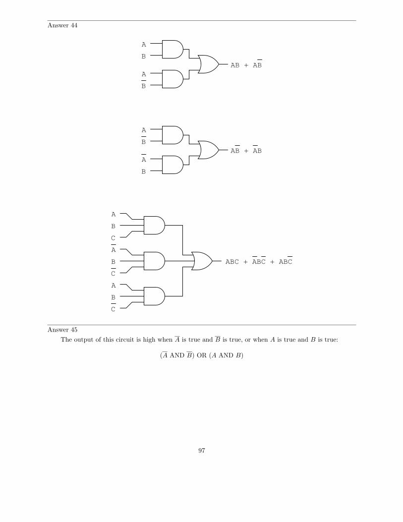
Answer 44
A
B
A
B
AB + AB
A
B
A
B
AB + AB
A
B
C
A
B
C
A
B
C
ABC + ABC + ABC
Answer 45
The output of this circuit is high when A is true and B is true, or when A is true and B is true:
(A AND B) OR (A AND B)
97

Answer 46
For the first truth table: the output of this circuit is high when A is true and B is true and C is true:
A AND B AND C
For the second truth table: the output of this circuit is high when A is true and B is true and C is true,or when A is true and B is true and C is true:
(A AND B AND C) OR (A AND B AND C)
Follow-up question: do you suspect we could write a formal Boolean expression for each of these truthtables? What would those expressions be, and what form would they be in (SOP or POS)?
Answer 47
To make things easier, I’ll associate each of the switches with a unique alphabetical letter:
• SW1 = A
• SW2 = B
• SW3 = C
• SW4 = D
Now, the Boolean expression:
ABCD
Answer 48
Original SOP expression:
ABC + ABC
Simplified expression and gate circuit:
BC
B
C
98

Answer 49
Original SOP expression and gate circuit:
A
B
C
A
B
C
A
B
C
ABC + ABC + ABC
Reduced expression and gate circuit:
A
B
C
AB + BC
99

Answer 50
Original SOP expression and relay circuit:
L1 L2
A
B
C
CR1
CR2
CR3
CR1
CR1
CR1
CR2
CR2
CR2
CR3
CR3
CR3
Output
Reduced expression and relay circuit:
L1 L2
A
B
C
CR1
CR2
CR3
CR1
Output
CR2
CR3
100

Answer 51
Simplest relay circuit possible:
L1 L2
A
C
B
Answer 52
A
B
A
B
A
B
C
101

Answer 53
A
B
A
B
(A + B)(A + B)
A
B
A
B
(A + B)(A + B)
A
B
C
A
B
C
A
B
C
(A+B+C)(A+B+C)(A+B+C)
Answer 54
At least one of the sum terms must be equal to zero.
Follow-up question: in order for one of these terms to be equal to zero, thus making the whole expressionequal to zero, what must be true about each of the Boolean literals (a literal is either a variable or thecomplement of a variable) within at least one of the sum terms?
102

Answer 55
Boolean expression for second gate circuit:
(A + B)(A + B)
Challenge question: we know that AB is also a valid Boolean expression for the first gate (NAND)circuit, in addition to A+B. Is there a rule you can think of to derive AB directly from an inspection of thetruth table? Can you apply this rule to the second gate circuit and the manipulate the resulting expressionusing Boolean laws and rules to obtain the expression (A + B)(A + B)?
Answer 56
SOP expression:
A B C + ABC + ABC + ABC
POS expression:
(A + B + C)(A + B + C)(A + B + C)(A + B + C)
Note: before deciding which expression is simpler, remember that the POS expression must bedistributed before we may apply any of the standard Boolean simplification rules.
Follow-up question: compare and contrast the procedures for generating SOP versus POS expressionsfrom a truth table. What states (1 or 0) are you looking for when writing each type of expression? Explainwhy.
Challenge question: what truth table scenarios do you suppose would ”favor” an SOP expression overa POS expression, and visa-versa? In other words, under what conditions does a truth table yield a simplerSOP expression, versus a simpler POS expression?
Answer 57
A + B + C
L1 L2
A
B
C
103

Answer 58
Original POS expression:
(A + B + C)(A + B + C)
Simplified expression and gate circuit:
A
B
C
AB + AB + C
Answer 59
Original POS expression:
(A + B + C)(A + B + C)
Simplified gate circuit:
A
B
Challenge question: what other single gate type will satisfy the truth table (besides a Negative-ORgate)?
Answer 60
SOP form: AB + AB
POS form: (A + B)(A + B)
I’ll let you do the algebra showing these two expressions to be equivalent!
L1 L2
A B
A B
104

Answer 61
AB
00
01
11
10
0 1C
11
1
1
0
0 0
0
Answer 62
1 1
1
1 11
00
0 00
0
0 0
ABCD
00
01
11
10
00 01 11 10
0 1
Answer 63
For this cluster of four 1’s, variables A and C are the only two inputs that change. Variables B and Dremain the same (B = 1 and D = 1) for each of the four ”high” outputs.
Answer 64
For this cluster of four 1’s, variables A and B are the only two inputs that remain constant for the four”1” conditions shown in the Karnaugh map. The simplified Boolean expression for the truth table is AB.See a pattern here?
Answer 65
ABCD
00
01
11
10
00 01 1110
1
1
1
1
0 0 0 0
00
0 0 0 0
0 0
Looking at this, we can still tell that B = 1 and D = 1 for all four ”high” output conditions, but thisis not apparent by proximity as it was before.
105

Answer 66
ABCD
00
01
11
10
00 01 11 10
1 1
11
0
0 0
0
0
0 0
0
0
0
0
0
1 1
11
0
0 0
0
0
0 0
0
0
0
0
0
00 01 11 10
00
01
11
10
1 1
11
0
0 0
0
0
0 0
0
0
0
0
0
1 1
11
0
0 0
0
0
0 0
0
0
0
0
0
Follow-up question: what does this problem tell us about grouping? In other words, how can we identifygroups of ”high” states without having to make oversized Karnaugh maps?
Answer 67
Proper grouping of 1’s in the Karnaugh map:
AB
00
01
11
10
0 1C
0
1
1
1
0
0
0
0
BC
AC
Answer 68
Any good introductory digital textbook will give the rules you need to do Karnaugh mapping. I leaveyou to research these rules for yourself!
106

Answer 69
Karnaugh map groupings with strict ”1” groups:
DB + DCA + DC B + C B A
00
01
11
10
00 01 11 10
11
0
0
1
1
1 1 1
1
DCBA
Karnaugh map groupings with ”don’t care” wildcards:
D + B + CA + C A
00
01
11
10
00 01 11 10
11
0
0
1
1
1 1 1
1
DCBA
Follow-up question: this question and answer merely focused on the a output for the BCD-to-7-segmentdecoder circuit. Imagine if we were to approach all seven outputs of the decoder circuit in these twofashions, first developing SOP expressions using strict groupings of ”1” outputs, and then using ”don’t care”wildcards. Which of these two approaches do you suppose would yield the simplest gate circuitry overall?What impact would the two different solutions have on the decoder circuit’s behavior for the six unspecifiedinput combinations 1010, 1011, 1100, 1101, 1110, and 1111?
Answer 70
Yes, you can use Karnaugh maps to generate POS expressions, not just SOP expressions!
Answer 71
Simple expression and relay circuit:
BC
L1 L2
B C
107

Answer 72
Simple expression and gate circuit:
AC + BCD
A
C
B
D
Challenge question: use Boolean algebra techniques to simplify the table’s raw SOP expression intominimal form without the use of a Karnaugh map.
Answer 73
Simple expression and gate circuit:
AC + AB D
A
C
B
D
Challenge question: use Boolean algebra techniques to simplify the table’s raw SOP expression intominimal form without the use of a Karnaugh map.
108

Answer 74
Simple expression and relay circuit:
BD + C D
L1 L2
B D
C D
Follow-up question: although the relay circuit shown above does satisfy the minimal SOP Booleanexpression, there is a way to make it simpler yet. Hint: done properly, you may eliminate one of the contactsin the circuit!
Challenge question: use Boolean algebra techniques to simplify the table’s raw SOP expression intominimal form without the use of a Karnaugh map.
Answer 75
Simple expression and relay circuit:
B + D
L1 L2
B
D
109

Answer 76
A B Output
00
0 1
01
1 1
A B Output
00
0 1
01
1 1
0
0
0
1
0
0
0
1
Negative-AND gate: A B
NOR gate: A + B
Answer 77
Negative-AND gates have the same functionality as NOR gates, and their equivalent Boolean expressionis as such:
A B
Negative-OR gates have the same functionality as NAND gates, and their equivalent Boolean expressionis as such:
A + B
Answer 78
DeMorgan’s Theorem is a rule for Boolean expressions, declaring how long complementation ”bars” areto be broken into shorter bars. I’ll let you research the terms of this rule, and explain how to apply it toBoolean expressions.
Answer 79
Simplified expression:
ABC
Answer 80
Simplified expression:
Y + XZ
Answer 81
Simplified expression:
(Expression is always equal to 1)
110
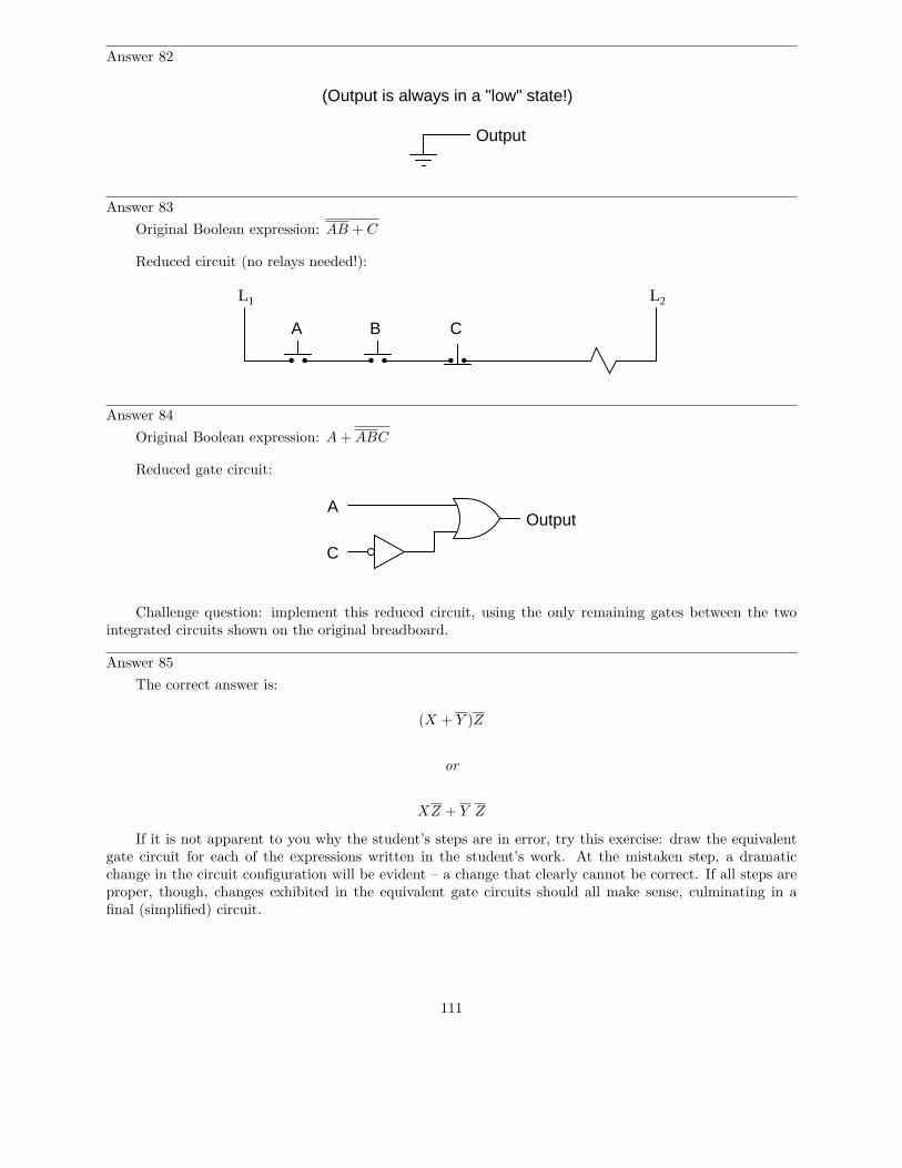
Answer 82
Output
(Output is always in a "low" state!)
Answer 83
Original Boolean expression: AB + C
Reduced circuit (no relays needed!):
L1 L2
A B C
Answer 84
Original Boolean expression: A + ABC
Reduced gate circuit:
A
C
Output
Challenge question: implement this reduced circuit, using the only remaining gates between the twointegrated circuits shown on the original breadboard.
Answer 85
The correct answer is:
(X + Y )Z
or
XZ + Y Z
If it is not apparent to you why the student’s steps are in error, try this exercise: draw the equivalentgate circuit for each of the expressions written in the student’s work. At the mistaken step, a dramaticchange in the circuit configuration will be evident – a change that clearly cannot be correct. If all steps areproper, though, changes exhibited in the equivalent gate circuits should all make sense, culminating in afinal (simplified) circuit.
111

Answer 86
Original Boolean expression: AB + AC
Reduced gate circuit:
Output
A
B
C
Answer 87
For the above solution: AA = A
Follow-up question: are there any other ways to use a NAND gate as an inverter? The method shownabove is not the only valid solution!
Answer 88
For the above solution: A + A = A
Follow-up question: are there any other ways to use a NOR gate as an inverter? The method shownabove is not the only valid solution!
Answer 89
This is a lot like algebraically manipulating equations: doing the exact same thing to both sides of anequation to arrive at a new equation that is more useful to us. I’ll let you figure out the details of how thisis done.
Answer 90
I’ll let you figure this one out on your own!
112

Answer 91
Using nothing but NAND gates:
A
B
C
Using nothing but NOR gates:
A
B
C
Answer 92
Output
A
B
113

Answer 93
Headlight signal
Ignition switch signalTo alarm
Follow-up question: suppose the alarm unit required more current than the final NAND gate couldsource. Add a transistor ”buffer” stage to the logic gate circuit to drive additional current to the alarm.
Challenge question: explain how the following NOR gate circuit performs the exact same logic functionwith fewer components:
Headlight signal
Ignition switch signal
To alarm
Answer 94
A
B
C
Output
Follow-up question: note the manner in which NOR gates are used as inverters in this circuit. Comparethis against the following (alternative) method:
NOR gate as inverter
Are there any distinct advantages you see to either method?
114

Answer 95
Original circuit expression:
A B C D E
Simplified expression and circuit:
A + B + C + D + E
L1 L2
A
B
C
D
E
Alarm solenoid
Follow-up question: which circuit (the original or the one show above) is more practical from a fail-safestandpoint? In other words, which circuit will give the safest result in the event of a switch or wiring failure?
Answer 96
Use circuit simulation software to verify your predicted and actual truth tables.
Answer 97
Use circuit simulation software to verify your predicted and actual truth tables.
Answer 98
Use circuit simulation software to verify your predicted and actual truth tables.
Answer 99
Be sure you meet with your instructor if you have any questions about what is expected for your project!
Answer 100
• Any low input guarantees a high output: NAND gate.• Any high input guarantees a low output: NOR gate.• Any high input guarantees a high output: OR gate.• Any difference in the inputs guarantees a high output: XOR gate.• Any difference in the inputs guarantees a low output: XNOR gate.
115

Answer 101
• B = A when Control is high: AND gate and XNOR gate.• B = A when Control is low: OR gate and XOR gate.• B = A when Control is high: NAND gate and XOR gate.• B = A when Control is low: NOR gate and XNOR gate.
Follow-up question: explain why XOR and XNOR gates are so useful as signal controllers.
Answer 102
• Output of OR gate U2 fails low: Gate U4 output stuck in the low state.
• Output of inverter gate U3 fails low: Gate U4 output stuck in the low state.
• Output of AND gate U1 fails high: Gate U4 output simply equal to D, no other inputs have any effecton U4’s output.
Answer 103
• Output of AND gate U2 fails low: Gate U3 output stuck in the high state.
• Output of AND gate U2 fails high: Gate U3 output simply equal to C, no other inputs have any effecton U3’s output.
• Output of inverter gate U1 fails low: Gate U3 output stuck in the high state.
Answer 104
• Output of NAND gate U2 fails low: Gate U4 output stuck in the low state.
• Output of buffer gate U3 fails low: Gate U4 output stuck in the low state.
• Output of NOR gate U1 fails high: Gate U4 output simply equal to CD, no other inputs have any effecton U4’s output.
Answer 105
• Pushbutton switch A fails open: Lamp 1 always energized, lamp 2 simply becomes inverse status ofpushbutton switch B.
• Relay coil CR2 fails open: Both lamp 1 and lamp 2 simply become inverse status of pushbutton switchA.
• Relay contact CR1-1 fails open: Lamp 1 simply becomes same status as pushbutton switch B.
• Relay contact CR2-1 fails shorted: Lamp 1 always energized.
• Relay contact CR2-2 fails shorted: Lamp 2 simply becomes inverse status of pushbutton switch A.
116

Answer 106
• Comparator U1 output fails low: Lamp energizes when Vin > Vref(low), even if Vin > Vref(high).
• Comparator U1 output fails high: Lamp energizes only when Vin < Vref(low).
• Comparator U2 output fails low: Lamp energizes only when Vin > Vref(high).
• Comparator U2 output fails high: Lamp energizes when Vin < Vref(high), even if Vin < Vref(low).
• Wire connecting VDD to Rpot1 fails open: Lamp refuses to energize.
Answer 107
U3 and Q1 are the most suspect components, given the behavior of the circuit. I’ll let you figure outwhat to measure next!
Answer 108
The AND gate may be bad, or it may be good. The test as described is inconclusive.
Follow-up question: what would have to be checked to make the described test procedure valid?
Answer 109
This is a problem worthy of a good in-class discussion with your peers! Of course, several things couldbe wrong in this circuit to cause lamp 1 to never energize. When you explain what measurements you wouldtake in isolating the problem, be sure to describe whether or not you are actuating either of the pushbuttonswitches when you take those measurements.
Answer 110
When factoring, you must look for variables common to each product term.
Follow-up question: if implemented with digital logic gates, which of these two expressions would requirethe fewest components?
A(B + C)
AB + AC
Answer 111
OutputA
B
Answer 112
OutputA
B
Answer 113
I’ll leave the proof up to you!
117

Answer 114
Original Boolean expression: AB BC
Reduced gate circuit:
A
BC
Answer 115
Original Boolean expression: ABCA
Reduced gate circuit:
A
B
C
Answer 116
Raw (unsimplified) expressions:
a = (D + C + B + A)(D + C + B + A)
b = (D + C + B + A)(D + C + B + A)
c = D + C + B + A
e = D C B A + D CBA + DCBA + DC B A
Challenge question: use the laws of Boolean algebra to simplify each of the above expressions into theirsimplest forms.
118

Notes
Notes 1
In order to familiarize students with the standard logic gate types, I like to given them practice withidentification and truth tables each day. Students need to be able to recognize these logic gate types at aglance, or else they will have difficulty analyzing circuits that use them.
Notes 2
In order to familiarize students with standard switch contact configurations, I like to given them practicewith identification and truth tables each day. Students need to be able to recognize these ladder logic sub-circuits at a glance, or else they will have difficulty analyzing more complex relay circuits that use them.
Notes 3
Some students with background in computers may ask if Boolean is the same as binary. The answerto this very good question is ”no.” Binary is simply a numeration system for expressing real numbers,while Boolean is a completely different number system (like integer numbers are to irrational numbers, forexample). It is possible to count arbitrarily high in binary, but you can only count as high as ”1” in Boolean.
Notes 4
Boolean algebra is a strange math, indeed. However, once students understand the limited scope ofBoolean quantities, the rationale for Boolean rules of arithmetic make sense. 1 + 1 must equal 1, becausethere is no such thing as ”2” in the Boolean world, and the answer certainly can’t be 0.
Notes 5
Students need to be able to readily associate fundamental Boolean operations with logic circuits. If theycan see the relationship between the ”strange” rules of Boolean arithmetic and something they are alreadyfamiliar with (i.e. truth tables), the association is made much easier.
Notes 6
Students need to be able to readily associate fundamental Boolean operations with logic circuits. If theycan see the relationship between the ”strange” rules of Boolean arithmetic and something they are alreadyfamiliar with (i.e. truth tables), the association is made much easier.
Notes 7
Students need to be able to readily associate fundamental Boolean operations with logic circuits. If theycan see the relationship between the ”strange” rules of Boolean arithmetic and something they are alreadyfamiliar with (i.e. truth tables), the association is made much easier.
Notes 8
These three equivalencies will be vital for students to master as they study combinational logic circuitsand complex relay logic circuits!
Notes 9
In order to familiarize students with Boolean algebra and how it relates to logic gate circuitry, I like togive them daily practice with questions such as this. Students need to be able to recognize these logic gatetypes at a glance, and also be able to associate the proper Boolean expression with each one, or else theywill have difficulty analyzing logic circuits later on.
119

Notes 10
In order to familiarize students with Boolean algebra and how it relates to relay logic circuitry, I like togive them daily practice with questions such as this. Students need to be able to figure out how each one ofthese ladder logic circuits works, and also be able to associate the proper Boolean expression with each one,or else they will have difficulty analyzing more complex relay circuits later on.
Notes 11
The process of converting gate circuits into Boolean expressions is really quite simple, if you proceedgate by gate. Have your students share whatever methods or ”tricks” they use to write the expressions withthe rest of the class.
Notes 12
The process of converting gate circuits into Boolean expressions is really quite simple, if you proceedgate by gate. Have your students share whatever methods or ”tricks” they use to write the expressions withthe rest of the class.
Notes 13
The process of converting gate circuits into Boolean expressions is really quite simple, if you proceedgate by gate. Have your students share whatever methods or ”tricks” they use to write the expressions withthe rest of the class.
Notes 14
The process of converting relay logic circuits into Boolean expressions is not quite as simple as it isconverting gate circuits into Boolean expressions, but it is manageable. Have your students share whatevermethods or ”tricks” they use to write the expressions with the rest of the class.
Notes 15
The process of converting relay logic circuits into Boolean expressions is not quite as simple as it isconverting gate circuits into Boolean expressions, but it is manageable. Have your students share whatevermethods or ”tricks” they use to write the expressions with the rest of the class.
Notes 16
The process of converting relay logic circuits into Boolean expressions is not quite as simple as it isconverting gate circuits into Boolean expressions, but it is manageable. Have your students share whatevermethods or ”tricks” they use to write the expressions with the rest of the class.
Notes 17
This is not a very complicated function to express or implement, the point of this question being mostlyto introduce students to a practical use of logic gates and Boolean algebra.
Notes 18
The process of converting Boolean expressions into logic gate circuits is not quite as simple as convertinggate circuits into Boolean expressions, but it is manageable. Have your students share whatever methods or”tricks” they use to write the expressions with the rest of the class.
Notes 19
To be honest, I had fun writing the scenarios for different parts of this problem. The evolution of thisalarm system is typical for an organization. Someone comes up with an idea, but it doesn’t meet all theneeds of someone else, so they input their own suggestions, and so on, and so on. Presenting scenarios suchas this not only prepare students for the politics of real work, but also underscore the need to ”what if?”thinking: to test the proposed solution before implementing it, so that unnecessary problems are avoided.
120

Notes 20
First things first: did students remember to include the power supply connections to each IC? This isa very common mistake!
In order to successfully develop a solution to this problem, of course, students must research the”pinouts” of each integrated circuit. If most students simply present the answer shown to them in theworksheet, challenge them during discussion to present alternative solutions.
Also, ask them this question: ”should we connect the unused inputs to either ground or VCC , or is itpermissible to leave the inputs floating?” Students should not just give an answer to this question, but beable to support their answer(s) with reasoning based on the construction of this type of logic circuit.
Notes 21
Ask your students to explain exactly how they figured out the ”Output” states to fill in the blanks inthe truth tables, for the different input combinations. Ask them also to compare and contrast this processwith that of figuring out the truth table for a given logic gate circuit.
Notes 22
Ask your students to explain exactly how they figured out the ”Output” states to fill in the blanks inthe truth tables, for the different input combinations. Ask them also to compare and contrast this processwith that of figuring out the truth table for a given logic gate circuit.
It is especially educational if you ask your students to suggest techniques for quickly determining truthtable states, based on certain features of the Boolean expression. For instance, there is a way we can tellthe first four ”Output” states in the truth table (reading top to bottom) will be 0 without having to plugvalues into the expression for B and C. Discuss with your students how we can look at the expression, seeingA as a multiplier for the sum within the parentheses, and immediately conclude that half of the truth tableoutputs will be 0.
Notes 23
The commutative, associative, and distributive laws of Boolean algebra are identical to the respectivelaws in real number algebra. These should not be difficult concepts for your students to understand. Thereal benefit of working through these examples is to associate gate and relay logic circuits with Booleanexpressions, and to see that Boolean algebra is nothing more than a symbolic means of representing electricaldiscrete-state (on/off) circuits. In relating otherwise abstract mathematical concepts to something tangible,students build a much better comprehension of the concepts.
Notes 24
Most of these Boolean rules are identical to their respective laws in real number algebra. These shouldnot be difficult concepts for your students to understand. Some of them, however, are unique to Booleanalgebra, having no analogue in real-number algebra. These unique rules cause students the most trouble!
An important benefit of working through these examples is to associate gate and relay logic circuits withBoolean expressions, and to see that Boolean algebra is nothing more than a symbolic means of representingelectrical discrete-state (on/off) circuits. In relating otherwise abstract mathematical concepts to somethingtangible, students build a much better comprehension of the concepts.
121

Notes 25
Quite frequently (and quite distressingly), I meet students who seem to have the most difficult timerelating algebraic rules in their general form to specific instances of reduction. For example, a student whocannot tell that the rule A + AB = A applies to the expression QR + R, or worse yet B + AB. This skillrequires time and hard work to master, because it is fundamentally a matter of abstraction: leaping fromliteral expressions to similar expressions, applying patterns from general rules to specific instances.
Questions such as this help students develop this abstraction ability. Let students explain how they”made the connection” between Boolean rules and the given reductions. Often, it helps to have a studentexplain the process to another student, because they are better able than you to put it into terms thestruggling students can understand.
Notes 26
Quite frequently (and quite distressingly), I meet students who seem to have the most difficult timerelating algebraic rules in their general form to specific instances of reduction. For example, a student whocannot tell that the rule A + AB = A applies to the expression QR + R, or worse yet B + AB. This skillrequires time and hard work to master, because it is fundamentally a matter of abstraction: leaping fromliteral expressions to similar expressions, applying patterns from general rules to specific instances.
Questions such as this help students develop this abstraction ability. Let students explain how they”made the connection” between Boolean rules and the given reductions. Often, it helps to have a studentexplain the process to another student, because they are better able than you to put it into terms thestruggling students can understand.
Notes 27
An interesting way to sharpen students’ understanding of algebraic techniques is to have them viewsomeone else’s incorrect work and find the error(s). Ultimately, algebraic reduction is really just an exercisein pattern recognition. Anything you can do to help your students recognize the correct patterns will helpthem become better at using algebra.
Notes 28
For some reason, many of my students (who enter my course weak in algebra skills) generally seemto have a lot of trouble with factoring, be it Boolean algebra or regular algebra. This is unfortunate, asfactoring is a powerful analytical tool. The ”trick,” if there is any such thing, is recognizing common variablesin different product terms, and identifying which of them should be factored out to reduce the expressionmost efficiently.
Like all challenging things, factoring takes time and practice to learn. There are no shortcuts, really.
Notes 29
Quite frequently (and quite distressingly), I meet students who seem to have the most difficult timerelating algebraic rules in their general form to specific instances of reduction. For example, a student whocannot tell that the rule A + AB = A applies to the expression QR + R, or worse yet B + AB. This skillrequires time and hard work to master, because it is fundamentally a matter of abstraction: leaping fromliteral expressions to similar expressions, applying patterns from general rules to specific instances.
Questions such as this help students develop this abstraction ability. Let students explain how they”made the connection” between Boolean rules and the given reductions. Often, it helps to have a studentexplain the process to another student, because they are better able than you to put it into terms thestruggling students can understand.
122
Notes 30
Many students find the substitution of Boolean variables (going from the A’s and B’s of canonicalrules to the different variables of real expressions where the rules are to be applied) very mysterious anddifficult. Problems such as this give them practice learning to identify the rules’ patterns despite similaritiesor differences in the actual variables (letters) used.
Notes 31
Have your students explain the entire process they used in answering this question: simplifying theexpression using Boolean algebra techniques, and developing a gate circuit from the simplified Booleanexpression. By having your students share their thought processes with the whole class, you will increasethe level of learning on the parts of presenter and viewer alike. Students presenting their solutions will gaina better understanding of how it works because the act of presenting helps consolidate what they alreadyknow. Students viewing the presentation will get to see another person’s technique (rather than just theinstructor’s), which will allow them to see examples of how to do these processes cast in slightly differentterms.
Notes 32
Have your students explain the entire process they used in answering this question: simplifying theexpression using Boolean algebra techniques, and developing a gate circuit from the simplified Booleanexpression. By having your students share their thought processes with the whole class, you will increasethe level of learning on the parts of presenter and viewer alike. Students presenting their solutions will gaina better understanding of how it works because the act of presenting helps consolidate what they alreadyknow. Students viewing the presentation will get to see another person’s technique (rather than just theinstructor’s), which will allow them to see examples of how to do these processes cast in slightly differentterms.
Notes 33
Have your students explain the entire process they used in answering this question: simplifying theexpression using Boolean algebra techniques, and developing a gate circuit from the simplified Booleanexpression. By having your students share their thought processes with the whole class, you will increasethe level of learning on the parts of presenter and viewer alike. Students presenting their solutions will gaina better understanding of how it works because the act of presenting helps consolidate what they alreadyknow. Students viewing the presentation will get to see another person’s technique (rather than just theinstructor’s), which will allow them to see examples of how to do these processes cast in slightly differentterms.
Notes 34
Have your students explain the entire process they used in simplifying the gate circuit: developingthe Boolean expression, simplifying that expression using Boolean algebra techniques, and then developinga new gate circuit from the simplified Boolean expression. By having your students share their thoughtprocesses with the whole class, you will increase the level of learning on the parts of presenter and vieweralike. Students presenting their solutions will gain a better understanding of how it works because the actof presenting helps consolidate what they already know. Students viewing the presentation will get to seeanother person’s technique (rather than just the instructor’s), which will allow them to see examples of howto do these processes cast in slightly different terms.
123

Notes 35
Have your students explain the entire process they used in simplifying the gate circuit: developingthe Boolean expression, simplifying that expression using Boolean algebra techniques, and then developinga new gate circuit from the simplified Boolean expression. By having your students share their thoughtprocesses with the whole class, you will increase the level of learning on the parts of presenter and vieweralike. Students presenting their solutions will gain a better understanding of how it works because the actof presenting helps consolidate what they already know. Students viewing the presentation will get to seeanother person’s technique (rather than just the instructor’s), which will allow them to see examples of howto do these processes cast in slightly different terms.
Notes 36
Have your students explain the entire process they used in simplifying the gate circuit: developingthe Boolean expression, simplifying that expression using Boolean algebra techniques, and then developinga new gate circuit from the simplified Boolean expression. By having your students share their thoughtprocesses with the whole class, you will increase the level of learning on the parts of presenter and vieweralike. Students presenting their solutions will gain a better understanding of how it works because the actof presenting helps consolidate what they already know. Students viewing the presentation will get to seeanother person’s technique (rather than just the instructor’s), which will allow them to see examples of howto do these processes cast in slightly different terms.
Notes 37
Have your students explain the entire process they used in simplifying the relay circuit: developingthe Boolean expression, simplifying that expression using Boolean algebra techniques, and then developinga new relay circuit from the simplified Boolean expression. By having your students share their thoughtprocesses with the whole class, you will increase the level of learning on the parts of presenter and vieweralike. Students presenting their solutions will gain a better understanding of how it works because the actof presenting helps consolidate what they already know. Students viewing the presentation will get to seeanother person’s technique (rather than just the instructor’s), which will allow them to see examples of howto do these processes cast in slightly different terms.
Notes 38
Have your students explain the entire process they used in simplifying the relay circuit: developingthe Boolean expression, simplifying that expression using Boolean algebra techniques, and then developinga new relay circuit from the simplified Boolean expression. By having your students share their thoughtprocesses with the whole class, you will increase the level of learning on the parts of presenter and vieweralike. Students presenting their solutions will gain a better understanding of how it works because the actof presenting helps consolidate what they already know. Students viewing the presentation will get to seeanother person’s technique (rather than just the instructor’s), which will allow them to see examples of howto do these processes cast in slightly different terms.
Notes 39
Have your students explain the entire process they used in simplifying the relay circuit: developingthe Boolean expression, simplifying that expression using Boolean algebra techniques, and then developinga new relay circuit from the simplified Boolean expression. By having your students share their thoughtprocesses with the whole class, you will increase the level of learning on the parts of presenter and vieweralike. Students presenting their solutions will gain a better understanding of how it works because the actof presenting helps consolidate what they already know. Students viewing the presentation will get to seeanother person’s technique (rather than just the instructor’s), which will allow them to see examples of howto do these processes cast in slightly different terms.
124

Notes 40
Have your students explain the entire process they used in simplifying the relay circuit: developingthe Boolean expression, simplifying that expression using Boolean algebra techniques, and then developinga new relay circuit from the simplified Boolean expression. By having your students share their thoughtprocesses with the whole class, you will increase the level of learning on the parts of presenter and vieweralike. Students presenting their solutions will gain a better understanding of how it works because the actof presenting helps consolidate what they already know. Students viewing the presentation will get to seeanother person’s technique (rather than just the instructor’s), which will allow them to see examples of howto do these processes cast in slightly different terms.
Notes 41
In order to familiarize students with the standard logic gate types, I like to given them practice withidentification and truth tables each day. Students need to be able to recognize these logic gate types at aglance, or else they will have difficulty analyzing circuits that use them.
Notes 42
In order to familiarize students with standard switch contact configurations, I like to given them practicewith identification and truth tables each day. Students need to be able to recognize these ladder logic sub-circuits at a glance, or else they will have difficulty analyzing more complex relay circuits that use them.
Notes 43
Even if your students have never heard of Boolean algebra before, they should still be able to determinewhich of the first four expressions are SOP and which are POS. If there is any confusion on this point, askyour students to define what ”sum” and ”product” mean, respectively, and then discuss what it means foran expression to be a product (singular) of sums (multiple), or a sum (singular) of products (multiple).
Notes 44
The translation from Boolean SOP to gate circuit should not be difficult. The point of this question isto get students thinking in terms of sum-of-products form, so they will be ready for the next step: linkingthis concept with truth tables.
Notes 45
Expressing truth table conditions ”verbally” is a way to introduce students to the concept of derivingBoolean expression from them.
Notes 46
I find this ”verbal” approach works well to introduce students to the concept of deriving Booleanexpressions from truth tables.
Be sure to ask your students what Boolean expressions they derived for both these truth tables. Giventhe answers in ”verbal” form, this should not be difficult for them!
Notes 47
This problem gives students a preview of sum-of-products notation. By examining the truth table, theyshould be able to determine that only one combination of switch settings (Boolean values) provides a ”1”output, and with a little thought they should be able to piece together this Boolean product statement.
Though this question may be advanced for some students (especially those weak in mathematicalreasoning skills), it is educational for all in the context of classroom discussion, where the thoughts ofstudents and instructor alike are exposed.
125

Notes 48
Challenge your students to implement the original SOP expression directly with logic gates (three-inputgates are acceptable to use).
Notes 49
Discuss with your students the utility of Boolean algebra as a circuit simplification tool. Ask yourstudents to compare the original and reduced logic gate circuits, and comment on such performance metricsas reliability, power consumption, maximum operating speed, etc.
Notes 50
Discuss with your students the utility of Boolean algebra as a circuit simplification tool. Ask yourstudents to compare the original and reduced logic gate circuits, and comment on such performance metricsas reliability, power consumption, maximum operating speed, etc.
Notes 51
Ask your students to show all their work in designing the relay circuit. By presenting their thoughtprocesses, not only do you help them consolidate their learning, but you also help the other studentsunderstand better by allowing them to learn from a peer.
Notes 52
The translation from Boolean POS to gate circuit should not be difficult. The point of this question isto get students thinking in terms of product-of-sums form, so they will be ready for the next step: linkingthis concept with truth tables.
Notes 53
The translation from Boolean POS to gate circuit should not be difficult. The point of this question isto get students thinking in terms of sum-of-products form, so they will be ready for the next step: linkingthis concept with truth tables.
Notes 54
This question foreshadows the derivation of POS expressions from truth tables. It also parallels thesubject of polynomial roots in real-number algebra. For instance, the polynomial x2
−2x−8 may be factoredas such:
(x − 4)(x + 2)
If we were to set this equation equal to zero, the roots of the equation would be 4 and -2: the values forx which would make either one of the terms equal to zero.
You may find this mini-review of ”normal” algebra to be helpful to your students, as they try tounderstand POS expressions.
Notes 55
The purpose of this question, if it isn’t obvious to you by now, is to have students ”discover” thetechnique for deriving POS expressions from truth tables, based on an evaluation of all the ”low” outputstates.
Your more advanced students should enjoy the challenge question, for it allows one to generate Booleanexpressions using a rule more similar to the first one learned: table-to-SOP.
126

Notes 56
This question is really asking students to compare and contrast SOP against POS expressions, ratherthan being a question specific to the given truth table. The actual expressions given in the answer are thereonly for ”drill,” so students may check their work. The real answers relate to the follow-up and challengequestions!
Notes 57
Ask students to contrast the difficulty of writing a POS expression for this function, versus an SOPexpression. The difference in complexity is great! Also, ask them to compare the circuitry equivalent to eachform of Boolean expression for this truth table. Which form yields a circuit with fewer gates?
Notes 58
Challenge your students to implement the original POS expression directly with logic gates (three-inputgates are acceptable to use). Is the ”simplified” POS expression shown in the answer really simpler in thecontext of real gate circuits? Ask your students what lesson this comparison holds for Boolean simplificationtechniques and their application to real-world circuits.
Notes 59
Challenge your students to implement the original POS expression directly with logic gates (three-inputgates are acceptable to use). Is the ”simplified” POS expression shown in the answer simpler in the context ofreal gate circuits? Ask your students what lesson this comparison holds for Boolean simplification techniquesand their application to real-world circuits.
Notes 60
Ask your students how many of them used a truth table to solve this problem. This is a helpful hint,as a truth table for an Ex-OR gate is easy to remember (or look up), and it provides a basis for easilyconstructing an SOP or POS expression.
The Exclusive-OR function is very, very useful in logic circuits. It is well worth students’ time tounderstand how to represent it in Boolean form (and no, not using that funny ⊕ symbol, either, butrepresenting it in a form where all the standard laws of Boolean algebra apply!).
Notes 61
Showing students that Karnaugh maps are really nothing more than truth tables in disguise helps themto more readily learn this powerful new tool.
Notes 62
Showing students that Karnaugh maps are really nothing more than truth tables in disguise helps themto more readily learn this powerful new tool.
Notes 63
This question introduces students to the Karnaugh reduction principle of detecting contradictoryvariables in a grouped set.
Notes 64
This question strongly suggests to students that the Karnaugh map is a graphical method of achievinga reduced-form SOP expression for a truth table. Once students realize Karnaugh mapping holds the key toescaping arduous Boolean algebra simplifications, their interest will be piqued!
127
Notes 65
You could simply tell your students that the input variables must be sequenced according to Gray codein order for Karnaugh mapping to work as a simplification tool, but this wouldn’t explain to students whyit needs to be such. This question shows students the purpose of Gray code sequencing in Karnaugh maps,by showing them the alternative (binary sequencing), and allowing them to see how the task of seekingnoncontradictory variables is complicated by it.
Notes 66
The concept of bit groups extending past the boundaries of a Karnaugh map tends to confuse students.In fact, it is about the only thing that tends to confuse students about Karnaugh maps! Simply telling themto group past the borders of the map doesn’t really teach them why the technique is valid. Here, they shouldsee with little difficulty why the technique works.
And, if for some reason they just can’t visualize bit groups past the boundaries of a Karnaugh map,they know they can just draw an oversized map and it will become obvious!
Notes 67
The purpose of this question is to illustrate how it is incorrect to identify clusters of arbitrary size ina Karnaugh map. A cluster of three, as seen in this scenario, leads to an incorrect conclusion. Of course,one could easily quote a textbook as to the proper numbers and patterns of 1’s to identify in a Karnaughmap, but it is so much more informative (in my opinion) to illustrate by example. Posing a dilemma such asthis makes students think about why the answer is wrong, rather than asking them to remember seeminglyarbitrary rules.
Notes 68
The answer speaks for itself here – let your students research these rules, and ask them exactly wherethey found them (including the page numbers in their textbook(s)!).
Notes 69
One of the points of this question is for students to realize that bigger groups are better, in that they yieldsimpler SOP terms. Also, students should realize that the ability to use ”don’t care” states as ”wildcard”placeholders in the Karnaugh map cells increases the chances of creating bigger groups.
Truth be known, I chose a pretty bad example to try to make an SOP expression from, since there areonly two non-zero output conditions out of ten! Formulating a POS expression would have been easier, butthat’s a subject for another question!
Notes 70
I am more interested in seeing students’ approach to this problem than acknowledgment of the answer(that Karnaugh maps may be used to generate SOP and POS expressions alike). Setting up a Karnaugh mapto see if a POS expression may be obtained for this truth table is not difficult to do, but many students areso unfamiliar/uncomfortable with ”experimenting” in this manner than they tend to freeze when presentedwith a problem like this. Without specific instructions on what to do, the obvious steps of ”try it and see”elude them.
It is your charge as their instructor to encourage an experimental mindset among your students. Donot simply tell them how to go about ”discovering” the answer on their own, for if you do you will rob themof an authentic discovery experience.
128

Notes 71
One of the things you may want to have your students share in front of the class is their Karnaughmaps, and how they grouped common output states to arrive at Boolean expression terms. I have foundthat an overhead (acetate) or computer-projected image of a blank Karnaugh map on a whiteboard serveswell to present Karnaugh maps on. This way, cell entries may be easily erased and re-drawn without havingto re-draw the map (grid lines) itself.
Ask your students to compare using a Karnaugh map versus using standard SOP/Boolean simplificationsto arrive at the simplest expression for this truth table. Which technique would they prefer to use, and why?
Notes 72
One of the things you may want to have your students share in front of the class is their Karnaughmaps, and how they grouped common output states to arrive at Boolean expression terms. I have foundthat an overhead (acetate) or computer-projected image of a blank Karnaugh map on a whiteboard serveswell to present Karnaugh maps on. This way, cell entries may be easily erased and re-drawn without havingto re-draw the map (grid lines) itself.
Notes 73
One of the things you may want to have your students share in front of the class is their Karnaughmaps, and how they grouped common output states to arrive at Boolean expression terms. I have foundthat an overhead (acetate) or computer-projected image of a blank Karnaugh map on a whiteboard serveswell to present Karnaugh maps on. This way, cell entries may be easily erased and re-drawn without havingto re-draw the map (grid lines) itself.
This is one of those situations where an important group ”wraps around” the edge of the Karnaughmap, and thus is likely to be overlooked by students.
Notes 74
One of the things you may want to have your students share in front of the class is their Karnaughmaps, and how they grouped common output states to arrive at Boolean expression terms. I have foundthat an overhead (acetate) or computer-projected image of a blank Karnaugh map on a whiteboard serveswell to present Karnaugh maps on. This way, cell entries may be easily erased and re-drawn without havingto re-draw the map (grid lines) itself.
This is one of those situations where an important group ”wraps around” the edge of the Karnaughmap, and thus is likely to be overlooked by students.
Notes 75
Given the preponderance of 1’s in this truth table, it is rational to try developing a POS expressionrather than an SOP expression. However, your students may find that the elegance of Karnaugh mappingmakes it easy enough to do it both ways! This is one question where you definitely want to have yourstudents explain their methods of solution in front of the class, and you definitely want them to see howKarnaugh maps could be used both ways (SOP and POS).
I have found that an overhead (acetate) or computer-projected image of a blank Karnaugh map ona whiteboard serves well to present Karnaugh maps on. This way, cell entries may be easily erased andre-drawn without having to re-draw the map (grid lines) itself.
Notes 76
Just a preview of DeMorgan’s Theorem here!
Notes 77
This question introduces DeMorgan’s Theorem via a process of discovery. Students, seeing that theseequivalent gates pairs have the same functionality, should be able to discern a general pattern (i.e. a rule)for breaking long bars in Boolean expressions.
129

Notes 78
There are many suitable references for students to be able to learn DeMorgan’s Theorem from. Letthem do the research on their own! Your task is to clarify any misunderstandings after they’ve done theirjobs.
Notes 79
Have your students demonstrate exactly what they did (step by step) to simplify this expression, sharingtheir problem-solving strategies with the whole class.
Notes 80
Have your students demonstrate exactly what they did (step by step) to simplify this expression, sharingtheir problem-solving strategies with the whole class.
Notes 81
Have your students demonstrate exactly what they did (step by step) to simplify this expression, sharingtheir problem-solving strategies with the whole class.
Ask your students to determine what a non-variable solution means for a circuit such as this in apractical sense. What would they suspect if they tried to simplify a digital circuit and obtained this kind ofresult?
Notes 82
Have your students explain the entire process they used in simplifying the gate circuit: developingthe Boolean expression, simplifying that expression using Boolean algebra techniques, and then developinga new gate circuit from the simplified Boolean expression. By having your students share their thoughtprocesses with the whole class, you will increase the level of learning on the parts of presenter and vieweralike. Students presenting their solutions will gain a better understanding of how it works because the actof presenting helps consolidate what they already know. Students viewing the presentation will get to seeanother person’s technique (rather than just the instructor’s), which will allow them to see examples of howto do these processes cast in slightly different terms.
Notes 83
Ask your students to explain what advantages there may be to using the simplified relay circuit ratherthan the original (more complex) relay circuit shown in the question. What significance does this lend tolearning Boolean algebra?
This is what Boolean algebra is really for: reducing the complexity of logic circuits. It is far too easy forstudents to lose sight of this fact, learning all the abstract rules and laws of Boolean algebra. Remember, inteaching Boolean algebra, you are supposed to be preparing students to perform manipulations of electroniccircuits, not just equations.
Notes 84
Ask your students to explain what advantages there may be to using the simplified gate circuit ratherthan the original (more complex) gate circuit shown in the question. What significance does this lend tolearning Boolean algebra?
This is what Boolean algebra is really for: reducing the complexity of logic circuits. It is far too easy forstudents to lose sight of this fact, learning all the abstract rules and laws of Boolean algebra. Remember, inteaching Boolean algebra, you are supposed to be preparing students to perform manipulations of electroniccircuits, not just equations.
130

Notes 85
An important aspect of long ”bars” for students to recognize is that they function as grouping symbols.When applying DeMorgan’s Theorem to breaking these bars, students often make the mistake of ignoringthe grouping implicit in the original bars.
I highly recommend you take your class through the exercise suggested in the answer, for those whodo not understand the nature of the mistake. Let students draw each expression’s equivalent circuit on theboard in front of the class so everyone can see, and then let them observe the dramatic change spoken ofat the place where the mistake is made. If students understand what DeMorgan’s Theorem means for anindividual gate (Neg-AND to NOR, Neg-OR to NAND, etc.), the gate diagrams will clearly reveal to themthat something has gone wrong at that step.
For comparison, perform the same step-by-step translation of the proper Boolean simplification into gatediagrams. The transitions between diagrams will make far more sense, and students should be able to get a”circuit’s view” of why complementation bars function as grouping symbols.
Notes 86
The Boolean simplification for this particular problem is tricky. Remind students that complementationbars act as grouping symbols, and that parentheses should be used when in doubt to maintain grouping after”breaking bars” with DeMorgan’s Theorem.
Ask your students to compare the ”simplified” circuit with the original circuit. Are any advantagesapparent to the version given in the answer? Certainly, the Boolean expression for that version of the circuitis simpler compared to that of the original circuit, but is the circuit itself significantly improved?
This question underscores an important lesson about Boolean algebra and logic simplification in general:just because a mathematical expression is simpler does not necessarily mean that the expression’s physicalrealization will be any simpler than the original!
Notes 87
Not only is the method shown in the answer not the only valid solution, but it may even be the worstone! Your students should be able to research or invent alternative inverter connections, so after askingthem to present their alternatives, ask the class as a whole to decide which solution is better. Ask them toconsider electrical parameters, such as propagation delay time and fan-out.
Notes 88
Not only is the method shown in the answer not the only valid solution, but it may even be the worstone! Your students should be able to research or invent alternative inverter connections, so after askingthem to present their alternatives, ask the class as a whole to decide which solution is better. Ask them toconsider electrical parameters, such as propagation delay time and fan-out.
Notes 89
This question is a precursor to having students create combinational gate circuits using nothing butNAND or NOR gates.
Notes 90
Notes 91
Gate universality is not just an esoteric property of logic gates. There are (or at least were) entire logicsystems made up of nothing but one of these gate types! I once worked with a fellow who maintained gasturbine control systems for crude oil pumping stations. He told me that he has seen one manufacturer’sturbine control system where the discrete logic was nothing but NAND gates, and another manufacturer’ssystem where the logic was nothing but NOR gates. Needless to say, it was a bit of a challenge for him totransition between the two manufacturers’ systems, since it was natural for him to ”get used to” one of thegate types after doing troubleshooting work on either type of system.
131

Notes 92
An interesting feature of this circuit is the final three NAND gates: two NAND gates feeding into athird NAND gate is equivalent to two AND gates feeding into an OR gate, thanks to DeMorgan’s Theorem!
Notes 93
This question is a really good one to ask your students how they arrived at a solution. It is easy enoughto simply look at the given answer and repeat it, but of course the intent of this question is to get studentsto think how they might design such a circuit completely on their own.
Notes 94
In my very first technical job, I worked as a CNC maintenance technician in a small machine shop,maintaining computer-controlled machine tools such as mills and lathes. A really neat project I got towork on at that job was the conversion of a 1970’s era American-made machine tool to modern Japanesecomputer control. A lot of logic in that old machine tool was implemented using relays, and we replacedthe cabinets full of relays with solid-state logic in the Japanese control computer. Actually, the solid statelogic was a programmable logic controller or PLC function inside the Japanese control computer rather thandiscrete semiconductor logic gates. However, we very well could have replaced relays with hard-wired gates.The purpose of this question, if you haven’t guessed by now, is to familiarize students with the concept ofreplacing electromechanical relays with semiconductor logic gates, especially identical logic gates such asNOR gates which are ”universal.”
Notes 95
Here students see that even though two circuits are functionally identical (at least according to theirrespective Boolean expressions), they may not behave quite the same under adverse conditions (i.e. faultedswitches or wiring). This is a very important thing for them to see, because it underscores the practicalneed to look beyond the immediate design criteria (Boolean function) and consider other parameters (failuremode).
Notes 96
It should be noted that the input states in this circuit are defined by the voltage levels, not by thecontact status. In other words, a closed contact equals a ”low” (0) logic state.
Here are some suggested Boolean expressions for your students to build gate circuits from:
• Output = AB + A
• Output = AB + A
• Output = (A + B)A• Output = (A + B)B• Output = A + B
• Output = A + B
• Output = AB
• Output = AB
132
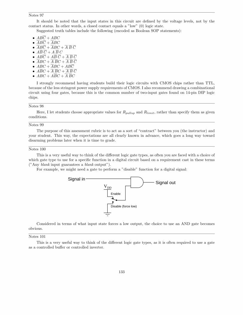
Notes 97
It should be noted that the input states in this circuit are defined by the voltage levels, not by thecontact status. In other words, a closed contact equals a ”low” (0) logic state.
Suggested truth tables include the following (encoded as Boolean SOP statements):
• ABC + ABC
• ABC + ABC
• ABC + ABC + A B C
• AB C + A B C
• ABC + AB C + A B C
• ABC + A BC + A B C
• ABC + ABC + ABC
• ABC + A BC + A B C
• ABC + ABC + A BC
I strongly recommend having students build their logic circuits with CMOS chips rather than TTL,because of the less stringent power supply requirements of CMOS. I also recommend drawing a combinationalcircuit using four gates, because this is the common number of two-input gates found on 14-pin DIP logicchips.
Notes 98
Here, I let students choose appropriate values for Rpullup and Rlimit, rather than specify them as givenconditions.
Notes 99
The purpose of this assessment rubric is to act as a sort of “contract” between you (the instructor) andyour student. This way, the expectations are all clearly known in advance, which goes a long way towarddisarming problems later when it is time to grade.
Notes 100
This is a very useful way to think of the different logic gate types, as often you are faced with a choice ofwhich gate type to use for a specific function in a digital circuit based on a requirement cast in these terms(”Any blank input guarantees a blank output”).
For example, we might need a gate to perform a ”disable” function for a digital signal:
VDD
Signal inSignal out
Enable
Disable (force low)
Considered in terms of what input state forces a low output, the choice to use an AND gate becomesobvious.
Notes 101
This is a very useful way to think of the different logic gate types, as it is often required to use a gateas a controlled buffer or controlled inverter.
133

Notes 102
The purpose of this question is to approach the domain of circuit troubleshooting from a perspective ofknowing what the fault is, rather than only knowing what the symptoms are. Although this is not necessarilya realistic perspective, it helps students build the foundational knowledge necessary to diagnose a faultedcircuit from empirical data. Questions such as this should be followed (eventually) by other questions askingstudents to identify likely faults based on measurements.
Notes 103
The purpose of this question is to approach the domain of circuit troubleshooting from a perspective ofknowing what the fault is, rather than only knowing what the symptoms are. Although this is not necessarilya realistic perspective, it helps students build the foundational knowledge necessary to diagnose a faultedcircuit from empirical data. Questions such as this should be followed (eventually) by other questions askingstudents to identify likely faults based on measurements.
Notes 104
The purpose of this question is to approach the domain of circuit troubleshooting from a perspective ofknowing what the fault is, rather than only knowing what the symptoms are. Although this is not necessarilya realistic perspective, it helps students build the foundational knowledge necessary to diagnose a faultedcircuit from empirical data. Questions such as this should be followed (eventually) by other questions askingstudents to identify likely faults based on measurements.
Notes 105
The purpose of this question is to approach the domain of circuit troubleshooting from a perspective ofknowing what the fault is, rather than only knowing what the symptoms are. Although this is not necessarilya realistic perspective, it helps students build the foundational knowledge necessary to diagnose a faultedcircuit from empirical data. Questions such as this should be followed (eventually) by other questions askingstudents to identify likely faults based on measurements.
Notes 106
The purpose of this question is to approach the domain of circuit troubleshooting from a perspective ofknowing what the fault is, rather than only knowing what the symptoms are. Although this is not necessarilya realistic perspective, it helps students build the foundational knowledge necessary to diagnose a faultedcircuit from empirical data. Questions such as this should be followed (eventually) by other questions askingstudents to identify likely faults based on measurements.
Notes 107
Discuss your students’ answers to this question and their troubleshooting strategies. The latter part ofthe question, where students are asked to explain what they would do next, is the most important part!
Notes 108
This is a very practical question, as it requires students to carefully consider what a three-input ANDgate ought to do under normal conditions, and how to set up a test that is indeed valid.
Notes 109
Be sure to leave plenty of classroom time for a discussion on troubleshooting this circuit. Electricaltroubleshooting is a difficult-to-develop skill, and it takes lots of time for some people to acquire. Being oneof the most valuable skills a technical person can possess, it is well worth the time invested!
The challenge question is very practical. Too many times I have seen students take meter measurementswhen their other senses provide enough data to render that step unnecessary. While there is nothing wrongwith using your meter to confirm a suspicion, the best troubleshooters use all their senses (safely, of course)in the isolation of system faults.
134

Notes 110
Factoring really does seem to be a more difficult pattern-recognition skill to master than distribution,the latter being self-explanatory to many students. The purpose of this question is to get students torecognize and articulate the pattern-matching process involved with factoring. Once students have a workingexplanation of how to factor (especially if phrased in their own words), they will be better equipped to doso when needed.
Notes 111
This question stands as an example of how NAND gates may be used to construct different types oflogic functions. In fact, with a sufficient quantity of NAND gates, any logic function may be built. This iswhy NAND gates are said to be ”universal.”
Notes 112
This question stands as an example of how NOR gates may be used to construct different types of logicfunctions. In fact, with a sufficient quantity of NOR gates, any logic function may be built. This is whyNOR gates are said to be ”universal.”
Notes 113
This is a very practical application of DeMorgan’s Theorem. Being able to use all NAND gates toimplement an SOP function is a bonus over having to use separate AND and OR integrated circuit packages(one IC instead of two in this particular case).
Notes 114
This particular circuit is an example of how a combinational logic function may be implemented usingnothing but NAND gates.
Notes 115
This particular circuit is an example of how a combinational logic function may be implemented usingnothing but NAND gates.
Notes 116
This shows a very practical example of SOP and POS Boolean forms, and why simplification is necessaryto reduce the number of required gates to a practical minimum.
135