Embed Size (px)
Citation preview

FRONT AXLE &FRONT SUSPENSION
SECTION FA
CONTENTSPRECAUTIONS AND PREPARATION............................2
Precautions ..................................................................2Special Service Tools ..................................................2Commercial Service Tools ...........................................3
NOISE, VIBRATION AND HARSHNESS (NVH)TROUBLESHOOTING .....................................................4
NVH Troubleshooting Chart.........................................4FRONT SUSPENSION SYSTEM ....................................5ON-VEHICLE SERVICE ..................................................6
Front Axle and Front Suspension Parts ......................6Front Wheel Bearing....................................................6Front Wheel Alignment ................................................7Drive Shaft .................................................................12
FRONT AXLE ................................................................13Manual-lock Free-running Hub..................................14Auto-lock Free-running Hub ......................................15
Description ............................................................15Inspection ..............................................................16Trouble Diagnosis For Noise ................................17
Wheel Hub and Rotor Disc........................................17Knuckle Spindle .........................................................19Drive Shaft .................................................................22Shock Absorber .........................................................28Torsion Bar Spring .....................................................28Stabilizer Bar .............................................................30Upper Link .................................................................31Lower Link .................................................................32Upper Ball Joint and Lower Ball Joint .......................33
SERVICE DATA AND SPECIFICATIONS (SDS) ..........34General Specifications...............................................34Inspection and Adjustment ........................................34
GI
MA
EM
LC
EC
FE
CL
MT
AT
TF
PD
FA
RA
BR
ST
RS
BT
HA
EL
IDX

SBR686C
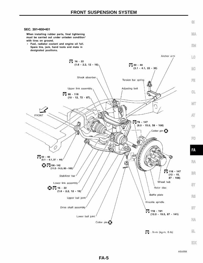
Precautions● When installing rubber parts, final tightening must be car-
ried out under unladen condition* with tires on ground.* Fuel, radiator coolant and engine oil full. Spare tire,
jack, hand tools and mats in designated positions.● Use flare nut wrench when removing and installing brake
tubes.● After installing removed suspension parts, check wheel
alignment and adjust if necessary.● Always torque brake lines when installing.
Special Service ToolsThe actual shapes of Kent-Moore tools may differ from those of special service tools illustrated here.
Tool number(Kent-Moore No.)Tool name
Description
ST29020001(J24319-01)Gear arm puller
NT694
Removing ball joint for knuckle spindle
a: 34 mm (1.34 in)b: 6.5 mm (0.256 in)c: 61.5 mm (2.421 in)
HT72520000(J25730-B)Ball joint remover
NT546
Removing tie-rod outer end
a: 33 mm (1.30 in)b: 50 mm (1.97 in)r: R11.5 mm (0.453 in)
KV401021S0( — )Bearing race drift
NT153
Installing wheel bearing outer race
KV40105400(J36001)Wheel bearinglock nut wrench
NT154
Removing and installing wheel bearing lock nut
KV40106800( — )Lower link bushingpuller
NT685
Removing and installing lower link bushing
PRECAUTIONS AND PREPARATION
FA-2

Commercial Service ToolsTool name Description
�1 Flare nut crowfoot
�2 Torque wrench
NT360
Removing and installing each brake piping
a: 10 mm (0.39 in)
GI
MA
EM
LC
EC
FE
CL
MT
AT
TF
PD
FA
RA
BR
ST
RS
BT
HA
EL
IDX
PRECAUTIONS AND PREPARATION
FA-3
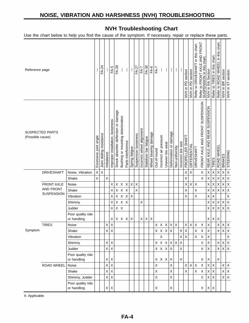
NVH Troubleshooting ChartUse the chart below to help you find the cause of the symptom. If necessary, repair or replace these parts.
Reference page —FA
-24
— FA-5
FA-2
8— — —
FA-2
7FA
-7FA
-30
FA-6
FA-7
— — — — —N
VH
inP
Dse
ctio
nN
VH
inP
Dse
ctio
nR
efer
toD
RIV
ES
HA
FT
inth
isch
art.
Ref
erto
FR
ON
TA
XLE
AN
DF
RO
NT
SU
SP
EN
SIO
Nin
this
char
t.N
VH
inR
AS
ectio
nR
efer
toT
IRE
Sin
this
char
t.R
efer
toR
OA
DW
HE
EL
inth
isch
art.
NV
Hin
BR
sect
ion
NV
Hin
ST
sect
ion
SUSPECTED PARTS(Possible cause)
Exc
essi
vejo
int
angl
eJo
int
slid
ing
resi
stan
ceIm
bala
nce
Impr
oper
inst
alla
tion,
loos
enes
sS
hock
abso
rber
defle
ctio
nor
dam
age
Bus
hing
orm
ount
ing
dete
riora
tion
Par
tsin
terf
eren
ceS
prin
gfa
tigue
Sus
pens
ion
loos
enes
sIn
corr
ect
whe
elal
ignm
ent
Sta
biliz
erba
rfa
tigue
Whe
elbe
arin
gda
mag
eO
ut-o
f-ro
und
Inco
rrec
tai
rpr
essu
reU
neve
ntir
ew
ear
Def
orm
atio
nor
dam
age
Non
-uni
form
ityIn
corr
ect
tire
size
PR
OP
ELL
ER
SH
AF
TD
IFF
ER
EN
TIA
LD
RIV
ES
HA
FT
FR
ON
TA
XLE
AN
DF
RO
NT
SU
SP
EN
SIO
N
RE
AR
AX
LEA
ND
RE
AR
SU
SP
EN
SIO
NT
IRE
SR
OA
DW
HE
EL
BR
AK
ES
ST
EE
RIN
GSymptom
DRIVESHAFT Noise, Vibration X X X X X X X X X X
Shake X X X X X X X X X
FRONT AXLEAND FRONTSUSPENSION
Noise X X X X X X X X X X X X X X
Shake X X X X X X X X X X X X
Vibration X X X X X X X X X X
Shimmy X X X X X X X X X X
Judder X X X X X X X X
Poor quality rideor handling X X X X X X X X X X X
TIRES Noise X X X X X X X X X X X X X X X
Shake X X X X X X X X X X X X X X
Vibration X X X X X X X
Shimmy X X X X X X X X X X X X X
Judder X X X X X X X X X X X X
Poor quality rideor handling X X X X X X X X X X
ROAD WHEEL Noise X X X X X X X X X X X X
Shake X X X X X X X X X X X
Shimmy, Judder X X X X X X X X X
Poor quality rideor handling X X X X X X X
X: Applicable
NOISE, VIBRATION AND HARSHNESS (NVH) TROUBLESHOOTING
FA-4
ASU058
GI
MA
EM
LC
EC
FE
CL
MT
AT
TF
PD
FA
RA
BR
ST
RS
BT
HA
EL
IDX
FRONT SUSPENSION SYSTEM
FA-5
SMA525A
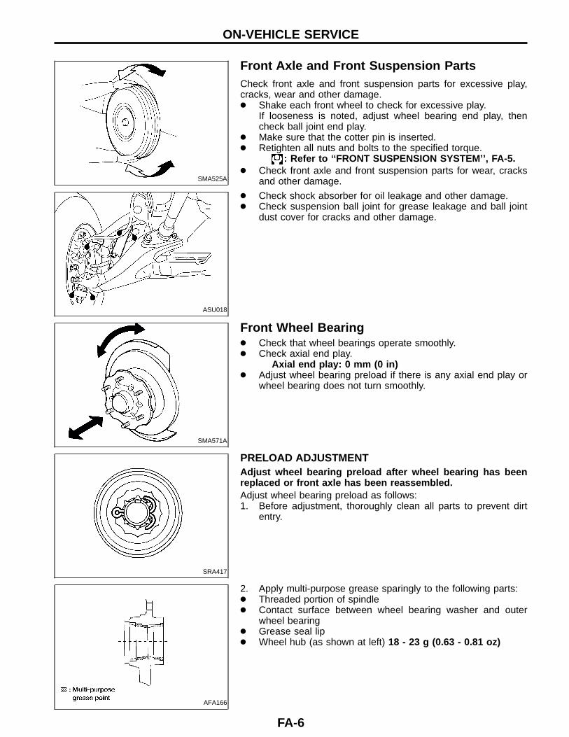
Front Axle and Front Suspension PartsCheck front axle and front suspension parts for excessive play,cracks, wear and other damage.● Shake each front wheel to check for excessive play.
If looseness is noted, adjust wheel bearing end play, thencheck ball joint end play.
● Make sure that the cotter pin is inserted.● Retighten all nuts and bolts to the specified torque.
: Refer to ‘‘FRONT SUSPENSION SYSTEM’’, FA-5.● Check front axle and front suspension parts for wear, cracks
and other damage.
ASU018
● Check shock absorber for oil leakage and other damage.● Check suspension ball joint for grease leakage and ball joint
dust cover for cracks and other damage.
SMA571A
Front Wheel Bearing● Check that wheel bearings operate smoothly.● Check axial end play.
Axial end play: 0 mm (0 in)● Adjust wheel bearing preload if there is any axial end play or
wheel bearing does not turn smoothly.
SRA417
PRELOAD ADJUSTMENTAdjust wheel bearing preload after wheel bearing has beenreplaced or front axle has been reassembled.Adjust wheel bearing preload as follows:1. Before adjustment, thoroughly clean all parts to prevent dirt
entry.
AFA166
2. Apply multi-purpose grease sparingly to the following parts:● Threaded portion of spindle● Contact surface between wheel bearing washer and outer
wheel bearing● Grease seal lip● Wheel hub (as shown at left) 18 - 23 g (0.63 - 0.81 oz)
ON-VEHICLE SERVICE
FA-6
AFA148
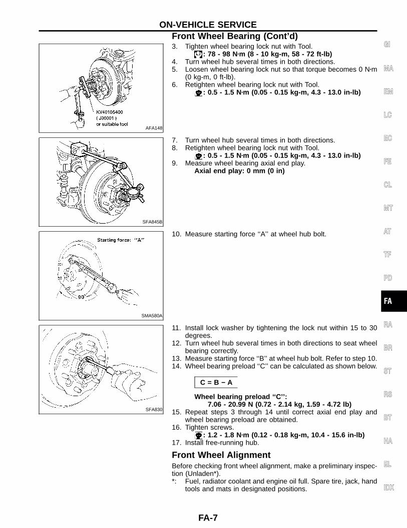
3. Tighten wheel bearing lock nut with Tool.: 78 - 98 N�m (8 - 10 kg-m, 58 - 72 ft-lb)
4. Turn wheel hub several times in both directions.5. Loosen wheel bearing lock nut so that torque becomes 0 N�m
(0 kg-m, 0 ft-lb).6. Retighten wheel bearing lock nut with Tool.
: 0.5 - 1.5 N�m (0.05 - 0.15 kg-m, 4.3 - 13.0 in-lb)
SFA845B
7. Turn wheel hub several times in both directions.8. Retighten wheel bearing lock nut with Tool.
: 0.5 - 1.5 N�m (0.05 - 0.15 kg-m, 4.3 - 13.0 in-lb)9. Measure wheel bearing axial end play.
Axial end play: 0 mm (0 in)
SMA580A
10. Measure starting force ‘‘A’’ at wheel hub bolt.
SFA830
11. Install lock washer by tightening the lock nut within 15 to 30degrees.
12. Turn wheel hub several times in both directions to seat wheelbearing correctly.
13. Measure starting force ‘‘B’’ at wheel hub bolt. Refer to step 10.14. Wheel bearing preload ‘‘C’’ can be calculated as shown below.
C = B − A
Wheel bearing preload ‘‘C’’:7.06 - 20.99 N (0.72 - 2.14 kg, 1.59 - 4.72 lb)
15. Repeat steps 3 through 14 until correct axial end play andwheel bearing preload are obtained.
16. Tighten screws.: 1.2 - 1.8 N�m (0.12 - 0.18 kg-m, 10.4 - 15.6 in-lb)
17. Install free-running hub.
Front Wheel AlignmentBefore checking front wheel alignment, make a preliminary inspec-tion (Unladen*).*: Fuel, radiator coolant and engine oil full. Spare tire, jack, hand
tools and mats in designated positions.
GI
MA
EM
LC
EC
FE
CL
MT
AT
TF
PD
FA
RA
BR
ST
RS
BT
HA
EL
IDX
ON-VEHICLE SERVICEFront Wheel Bearing (Cont’d)
FA-7
SFA975B
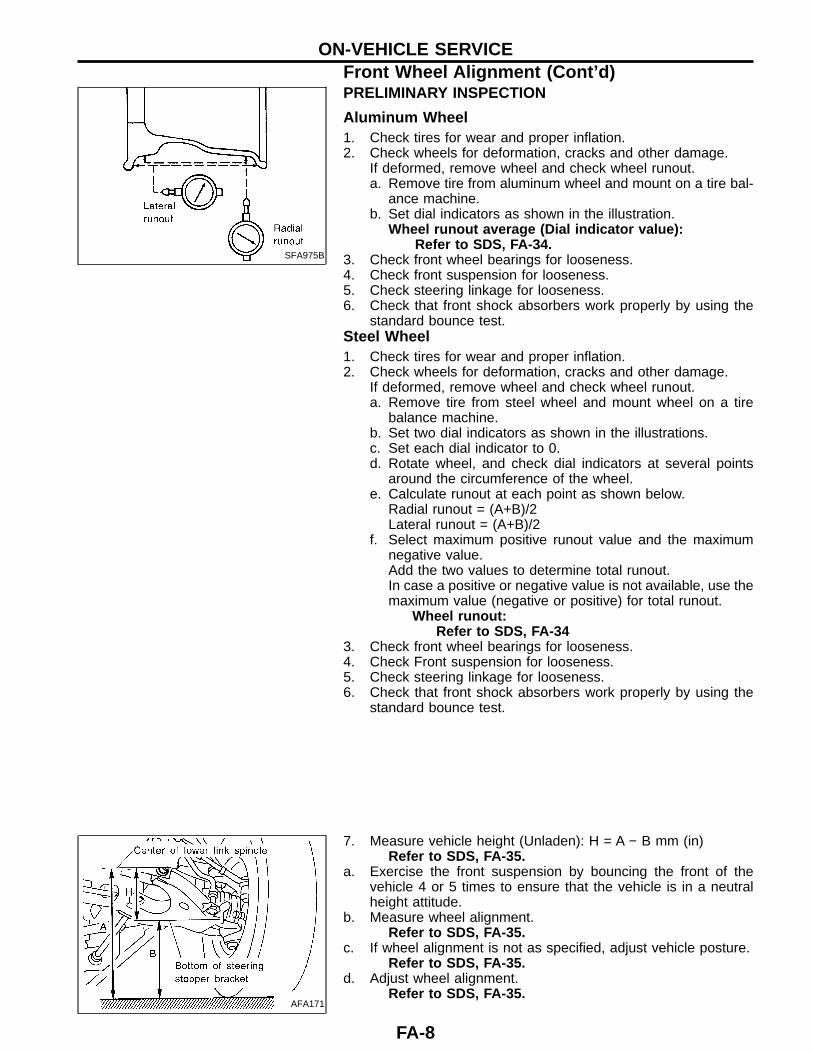
PRELIMINARY INSPECTION
Aluminum Wheel1. Check tires for wear and proper inflation.2. Check wheels for deformation, cracks and other damage.
If deformed, remove wheel and check wheel runout.a. Remove tire from aluminum wheel and mount on a tire bal-
ance machine.b. Set dial indicators as shown in the illustration.
Wheel runout average (Dial indicator value):Refer to SDS, FA-34.
3. Check front wheel bearings for looseness.4. Check front suspension for looseness.5. Check steering linkage for looseness.6. Check that front shock absorbers work properly by using the
standard bounce test.Steel Wheel1. Check tires for wear and proper inflation.2. Check wheels for deformation, cracks and other damage.
If deformed, remove wheel and check wheel runout.a. Remove tire from steel wheel and mount wheel on a tire
balance machine.b. Set two dial indicators as shown in the illustrations.c. Set each dial indicator to 0.d. Rotate wheel, and check dial indicators at several points
around the circumference of the wheel.e. Calculate runout at each point as shown below.
Radial runout = (A+B)/2Lateral runout = (A+B)/2
f. Select maximum positive runout value and the maximumnegative value.Add the two values to determine total runout.In case a positive or negative value is not available, use themaximum value (negative or positive) for total runout.
Wheel runout:Refer to SDS, FA-34
3. Check front wheel bearings for looseness.4. Check Front suspension for looseness.5. Check steering linkage for looseness.6. Check that front shock absorbers work properly by using the
standard bounce test.
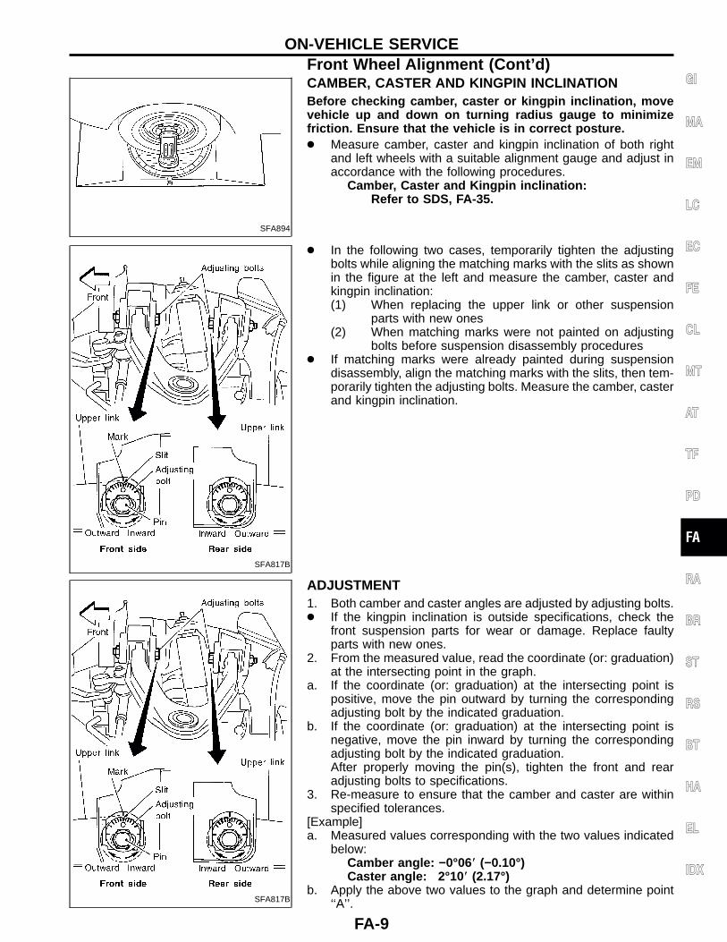
AFA171
7. Measure vehicle height (Unladen): H = A − B mm (in)Refer to SDS, FA-35.
a. Exercise the front suspension by bouncing the front of thevehicle 4 or 5 times to ensure that the vehicle is in a neutralheight attitude.
b. Measure wheel alignment.Refer to SDS, FA-35.
c. If wheel alignment is not as specified, adjust vehicle posture.Refer to SDS, FA-35.
d. Adjust wheel alignment.Refer to SDS, FA-35.
ON-VEHICLE SERVICEFront Wheel Alignment (Cont’d)
FA-8
SFA894
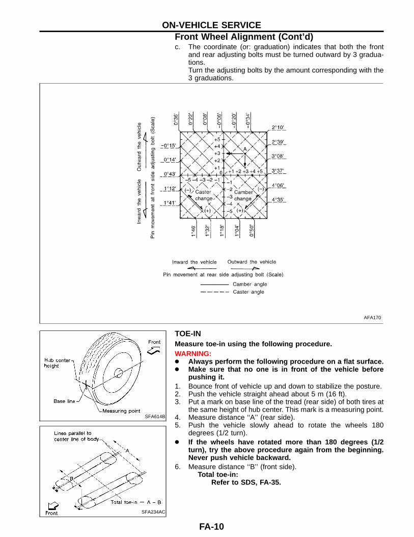
CAMBER, CASTER AND KINGPIN INCLINATIONBefore checking camber, caster or kingpin inclination, movevehicle up and down on turning radius gauge to minimizefriction. Ensure that the vehicle is in correct posture.● Measure camber, caster and kingpin inclination of both right
and left wheels with a suitable alignment gauge and adjust inaccordance with the following procedures.
Camber, Caster and Kingpin inclination:Refer to SDS, FA-35.
SFA817B
● In the following two cases, temporarily tighten the adjustingbolts while aligning the matching marks with the slits as shownin the figure at the left and measure the camber, caster andkingpin inclination:(1) When replacing the upper link or other suspension
parts with new ones(2) When matching marks were not painted on adjusting
bolts before suspension disassembly procedures● If matching marks were already painted during suspension
disassembly, align the matching marks with the slits, then tem-porarily tighten the adjusting bolts. Measure the camber, casterand kingpin inclination.
SFA817B
ADJUSTMENT1. Both camber and caster angles are adjusted by adjusting bolts.● If the kingpin inclination is outside specifications, check the
front suspension parts for wear or damage. Replace faultyparts with new ones.
2. From the measured value, read the coordinate (or: graduation)at the intersecting point in the graph.
a. If the coordinate (or: graduation) at the intersecting point ispositive, move the pin outward by turning the correspondingadjusting bolt by the indicated graduation.
b. If the coordinate (or: graduation) at the intersecting point isnegative, move the pin inward by turning the correspondingadjusting bolt by the indicated graduation.After properly moving the pin(s), tighten the front and rearadjusting bolts to specifications.
3. Re-measure to ensure that the camber and caster are withinspecified tolerances.
[Example]a. Measured values corresponding with the two values indicated
below:Camber angle: −0°06� (−0.10°)Caster angle: 2°10� (2.17°)
b. Apply the above two values to the graph and determine point‘‘A’’.
GI
MA
EM
LC
EC
FE
CL
MT
AT
TF
PD
FA
RA
BR
ST
RS
BT
HA
EL
IDX
ON-VEHICLE SERVICEFront Wheel Alignment (Cont’d)
FA-9
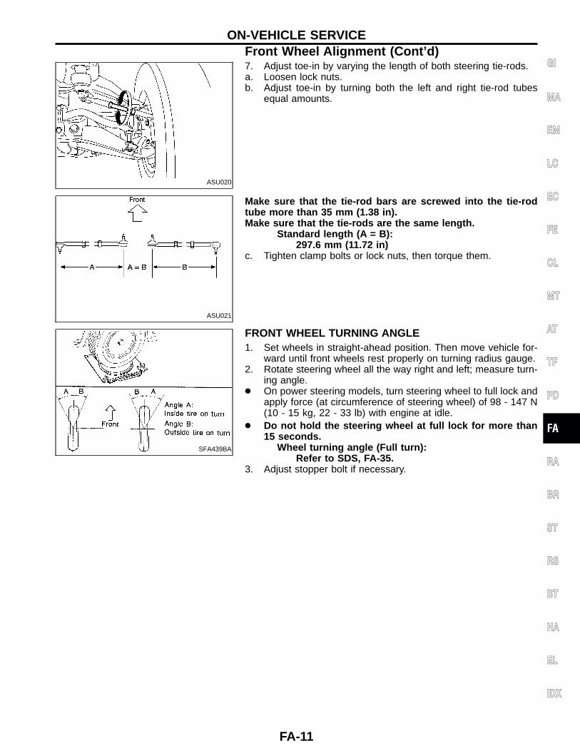
c. The coordinate (or: graduation) indicates that both the frontand rear adjusting bolts must be turned outward by 3 gradua-tions.Turn the adjusting bolts by the amount corresponding with the3 graduations.
AFA170
SFA614B
SFA234AC
TOE-INMeasure toe-in using the following procedure.WARNING:● Always perform the following procedure on a flat surface.● Make sure that no one is in front of the vehicle before
pushing it.1. Bounce front of vehicle up and down to stabilize the posture.2. Push the vehicle straight ahead about 5 m (16 ft).3. Put a mark on base line of the tread (rear side) of both tires at
the same height of hub center. This mark is a measuring point.4. Measure distance ‘‘A’’ (rear side).5. Push the vehicle slowly ahead to rotate the wheels 180
degrees (1/2 turn).● If the wheels have rotated more than 180 degrees (1/2
turn), try the above procedure again from the beginning.Never push vehicle backward.
6. Measure distance ‘‘B’’ (front side).Total toe-in:
Refer to SDS, FA-35.
ON-VEHICLE SERVICEFront Wheel Alignment (Cont’d)
FA-10
ASU020
7. Adjust toe-in by varying the length of both steering tie-rods.a. Loosen lock nuts.b. Adjust toe-in by turning both the left and right tie-rod tubes
equal amounts.
ASU021
Make sure that the tie-rod bars are screwed into the tie-rodtube more than 35 mm (1.38 in).Make sure that the tie-rods are the same length.
Standard length (A = B):297.6 mm (11.72 in)
c. Tighten clamp bolts or lock nuts, then torque them.
SFA439BA
FRONT WHEEL TURNING ANGLE1. Set wheels in straight-ahead position. Then move vehicle for-
ward until front wheels rest properly on turning radius gauge.2. Rotate steering wheel all the way right and left; measure turn-
ing angle.● On power steering models, turn steering wheel to full lock and
apply force (at circumference of steering wheel) of 98 - 147 N(10 - 15 kg, 22 - 33 lb) with engine at idle.
● Do not hold the steering wheel at full lock for more than15 seconds.
Wheel turning angle (Full turn):Refer to SDS, FA-35.
3. Adjust stopper bolt if necessary.
GI
MA
EM
LC
EC
FE
CL
MT
AT
TF
PD
FA
RA
BR
ST
RS
BT
HA
EL
IDX
ON-VEHICLE SERVICEFront Wheel Alignment (Cont’d)
FA-11

AFA169
Standard length ‘‘L2’’ :Except P265/70R15 tire:26.5 mm (1.043 in)(Length before cap is mounted)P265/70R15 tire:30.0 mm (1.2 in)(Length before cap is mounted)
SFA901
Drive Shaft● Check for grease leakage and damage.
ON-VEHICLE SERVICEFront Wheel Alignment (Cont’d)
FA-12

AFA168
GI
MA
EM
LC
EC
FE
CL
MT
AT
TF
PD
FA
RA
BR
ST
RS
BT
HA
EL
IDX
FRONT AXLE
FA-13
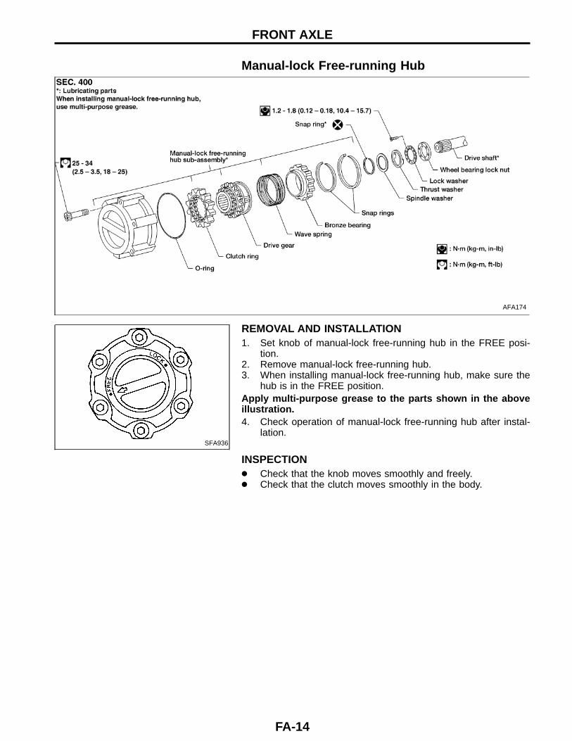
Manual-lock Free-running Hub
AFA174
SFA936
REMOVAL AND INSTALLATION1. Set knob of manual-lock free-running hub in the FREE posi-
tion.2. Remove manual-lock free-running hub.3. When installing manual-lock free-running hub, make sure the
hub is in the FREE position.Apply multi-purpose grease to the parts shown in the aboveillustration.4. Check operation of manual-lock free-running hub after instal-
lation.
INSPECTION● Check that the knob moves smoothly and freely.● Check that the clutch moves smoothly in the body.
FRONT AXLE
FA-14

Auto-lock Free-running HubDESCRIPTIONAuto-lock free-running hubs are locked by placing the transfer caseinto the 4WD mode and moving the vehicle. They are unlocked byplacing the transfer case into the 2WD mode and moving thevehicle in reverse gear in a straight line for at least 2-3 meters(7-10 feet).In most cases, the ‘‘ratcheting’’ noise sometimes heard in auto-lockfree-running hubs occurs when one hub is locked and the oppositehub is unlocked. The noise is heard in the side opposite to thelocked hub. For example, if the noise is heard at the left front wheel,the right front hub is still locked and is not unlocking. This condi-tion may be caused by a mechanical condition in one of the hubsor by incorrect operation on the part of the vehicle driver, forexample by not backing up in a straight line to unlock the hubs, bynot backing up enough, or by shifting into 4WD at too high a vehiclespeed, etc.The ratcheting noise does not necessarily cause damage to thegood hub. If the noise is caused by incorrect operation, counsel thedriver of the vehicle. If replacement is necessary, replace only thedefective part. It is not necessary to replace auto-lock free-runninghubs in pairs.Use the trouble diagnosis chart to isolate the cause of the noise.Refer to ‘‘TROUBLE DIAGNOSIS FOR NOISE’’, FA-17.
AAX008
GI
MA
EM
LC
EC
FE
CL
MT
AT
TF
PD
FA
RA
BR
ST
RS
BT
HA
EL
IDX
FRONT AXLE
FA-15
SFA828B
AFA143
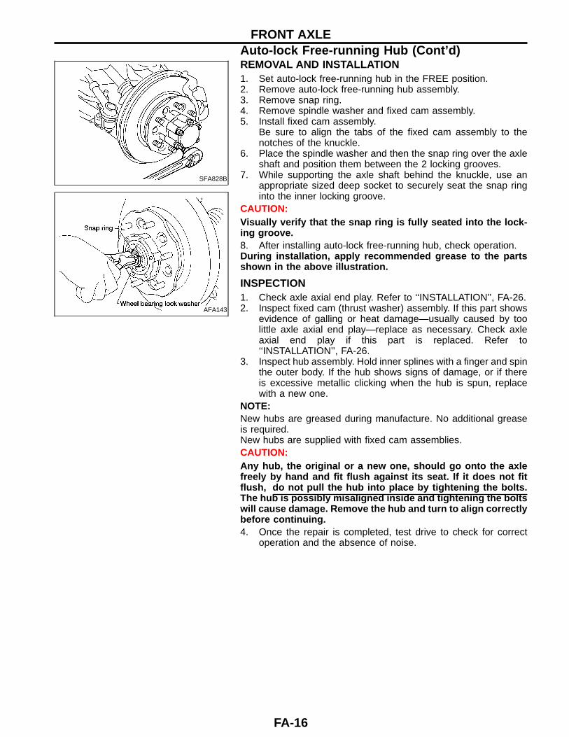
REMOVAL AND INSTALLATION1. Set auto-lock free-running hub in the FREE position.2. Remove auto-lock free-running hub assembly.3. Remove snap ring.4. Remove spindle washer and fixed cam assembly.5. Install fixed cam assembly.
Be sure to align the tabs of the fixed cam assembly to thenotches of the knuckle.
6. Place the spindle washer and then the snap ring over the axleshaft and position them between the 2 locking grooves.
7. While supporting the axle shaft behind the knuckle, use anappropriate sized deep socket to securely seat the snap ringinto the inner locking groove.
CAUTION:Visually verify that the snap ring is fully seated into the lock-ing groove.8. After installing auto-lock free-running hub, check operation.During installation, apply recommended grease to the partsshown in the above illustration.
INSPECTION1. Check axle axial end play. Refer to ‘‘INSTALLATION’’, FA-26.2. Inspect fixed cam (thrust washer) assembly. If this part shows
evidence of galling or heat damage—usually caused by toolittle axle axial end play—replace as necessary. Check axleaxial end play if this part is replaced. Refer to‘‘INSTALLATION’’, FA-26.
3. Inspect hub assembly. Hold inner splines with a finger and spinthe outer body. If the hub shows signs of damage, or if thereis excessive metallic clicking when the hub is spun, replacewith a new one.
NOTE:New hubs are greased during manufacture. No additional greaseis required.New hubs are supplied with fixed cam assemblies.CAUTION:Any hub, the original or a new one, should go onto the axlefreely by hand and fit flush against its seat. If it does not fitflush, do not pull the hub into place by tightening the bolts.The hub is possibly misaligned inside and tightening the boltswill cause damage. Remove the hub and turn to align correctlybefore continuing.4. Once the repair is completed, test drive to check for correct
operation and the absence of noise.
FRONT AXLEAuto-lock Free-running Hub (Cont’d)
FA-16
TROUBLE DIAGNOSIS FOR NOISE
Symptom Possible cause Repair order
Ratchet noise in hub after shifting thetransfer case into 4WD at speeds higherthan 40 km/h (25 MPH).
1. Shifting into 4WD at higher speeds isdifficult and may cause damage to thetransfer case
1. Stop the vehicle or decrease speed toless than 40 km/h (25 MPH). Return thetransfer case lever to the 2H positiononce, then re-shift to the 4H position.Move forward until both hubs lock.
Ratchet noise in hub after shifting orattempting to shift the transfer case into4WD at speeds less than 40 km/h (25MPH).
1. Transfer case was not fully engaged orshifting was stopped halfway so thatonly one hub locked
1. Make sure the 4WD lamp on the dashis ‘‘ON’’ when shifting into 4WD. Slowor stop the vehicle. Shift into 2H, thenback to 4H. Move forward until the hubslock.
Ratchet noise in hub after shifting thetransfer case into 4WD on snowy ormuddy roads or on slopes.
1. If the rear wheels slip during the hublocking operation, noise can occur inthe hubs
1. Reduce engine speed and drive forwardslowly. The hubs will lock evenly andthe noise will stop.
Ratchet noise in hub after shifting thetransfer case into 2WD and backing up tounlock the hubs.
1. The hubs may not be fully released 1. Stop the vehicle, make sure the transfercase lever is fully in the 2H position,then back up slowly in a straight line atleast 2-3 meters (7-10 feet)
Ratchet noise in hub when driving inextremely cold weather.
1. The viscosity of differential oil growshigher in extreme cold, increasing thepossibility that one hub may lock. Alower viscosity differential fluid may berequired for extreme cold temperatures.See owner’s manual
1. Shift the transfer case into 4H and drivethe vehicle for 10 minutes or more towarm the differential oil. Then shift to2WD and back up in a straight line forat least 2-3 meters (7-10 feet) to disen-gage the hubs.
Continual ratchet noise in one wheel whenmoving forward.
1. A hub may be mechanically locked,either by damage or misinstallation
1. Remove hubs and inspect. Refer to‘‘Inspection’’, FA-16. Pay special atten-tion to the hub opposite the noisy side.The ratcheting does not necessarilycause damage to the good hub.
SFA825B
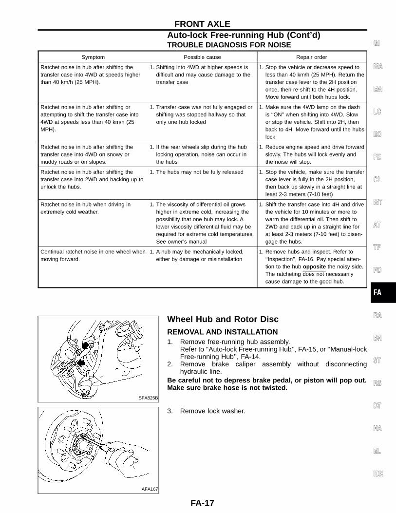
Wheel Hub and Rotor DiscREMOVAL AND INSTALLATION1. Remove free-running hub assembly.
Refer to ‘‘Auto-lock Free-running Hub’’, FA-15, or ‘‘Manual-lockFree-running Hub’’, FA-14.
2. Remove brake caliper assembly without disconnectinghydraulic line.
Be careful not to depress brake pedal, or piston will pop out.Make sure brake hose is not twisted.
AFA167
3. Remove lock washer.
GI
MA
EM
LC
EC
FE
CL
MT
AT
TF
PD
FA
RA
BR
ST
RS
BT
HA
EL
IDX
FRONT AXLEAuto-lock Free-running Hub (Cont’d)
FA-17
AFA141
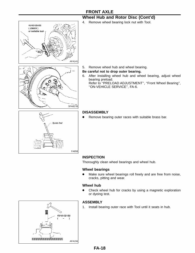
4. Remove wheel bearing lock nut with Tool.
SFA827B
5. Remove wheel hub and wheel bearing.Be careful not to drop outer bearing.6. After installing wheel hub and wheel bearing, adjust wheel
bearing preload.Refer to ‘‘PRELOAD ADJUSTMENT’’, ‘‘Front Wheel Bearing’’,‘‘ON-VEHICLE SERVICE’’, FA-6.
FA858
DISASSEMBLY● Remove bearing outer races with suitable brass bar.
INSPECTIONThoroughly clean wheel bearings and wheel hub.
Wheel bearings● Make sure wheel bearings roll freely and are free from noise,
cracks, pitting and wear.
Wheel hub● Check wheel hub for cracks by using a magnetic exploration
or dyeing test.
AFA156
ASSEMBLY1. Install bearing outer race with Tool until it seats in hub.
FRONT AXLEWheel Hub and Rotor Disc (Cont’d)
FA-18

SBR400DA
2. Install the sensor rotor using suitable drift and press. (Modelswith ABS)Always replace sensor rotor with new one.Pay attention to the direction of front sensor rotor as shown infigure.
AFA166
3. Pack multi-purpose grease in wheel hub and hub cap.
SFA459B
4. Apply multi-purpose grease to each bearing cone.5. Pack grease seal lip with multi-purpose grease, then install it
into wheel hub with suitable drift.
SFA828B
Knuckle SpindleREMOVAL1. Remove free-running hub assembly.
Refer to ‘‘Auto-lock Free-running Hub’’, FA-15, or ‘‘Manual-lockFree-running Hub’’, FA-14.
2. Remove wheel hub and rotor disc.Refer to ‘‘Wheel Hub and Rotor Disc’’, FA-17.
AFA165
3. Separate drive shaft from knuckle spindle by slightly tappingdrive shaft end.
GI
MA
EM
LC
EC
FE
CL
MT
AT
TF
PD
FA
RA
BR
ST
RS
BT
HA
EL
IDX
FRONT AXLEWheel Hub and Rotor Disc (Cont’d)
FA-19

AFA139
4. Separate tie-rod from knuckle spindle with Tool.Install stud nut conversely on stud bolt so as not to damagestud bolt.
SFA829B
5. Separate knuckle spindle from ball joints.a. Loosen (do not remove) upper and lower ball joint tightening
nuts.
SFA079
b. Separate knuckle spindle from upper and lower ball joint studswith Tool.
During above operation, never remove ball joint nuts whichare loosened in step (a) above.
Tool:HT72520000 (J25730-B)
SFA830B
c. Remove ball joint tightening nuts.Support lower link with jack.d. Remove knuckle spindle from upper and lower links.
INSPECTION
Knuckle spindle● Check knuckle spindle for deformation, cracks and other dam-
age by using a magnetic exploration or dyeing test.
Needle bearing● Check needle bearing for wear, scratches, pitting, flaking and
burn marks.
FRONT AXLEKnuckle Spindle (Cont’d)
FA-20
AFA164
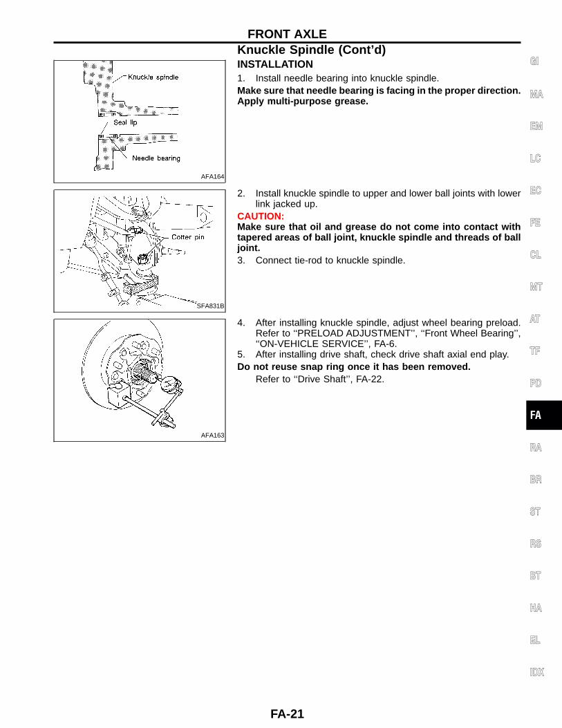
INSTALLATION1. Install needle bearing into knuckle spindle.Make sure that needle bearing is facing in the proper direction.Apply multi-purpose grease.
SFA831B
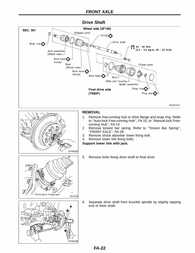
2. Install knuckle spindle to upper and lower ball joints with lowerlink jacked up.
CAUTION:Make sure that oil and grease do not come into contact withtapered areas of ball joint, knuckle spindle and threads of balljoint.3. Connect tie-rod to knuckle spindle.
AFA163
4. After installing knuckle spindle, adjust wheel bearing preload.Refer to ‘‘PRELOAD ADJUSTMENT’’, ‘‘Front Wheel Bearing’’,‘‘ON-VEHICLE SERVICE’’, FA-6.
5. After installing drive shaft, check drive shaft axial end play.Do not reuse snap ring once it has been removed.
Refer to ‘‘Drive Shaft’’, FA-22.
GI
MA
EM
LC
EC
FE
CL
MT
AT
TF
PD
FA
RA
BR
ST
RS
BT
HA
EL
IDX
FRONT AXLEKnuckle Spindle (Cont’d)
FA-21
Drive Shaft
SFA874-B
SFA832B
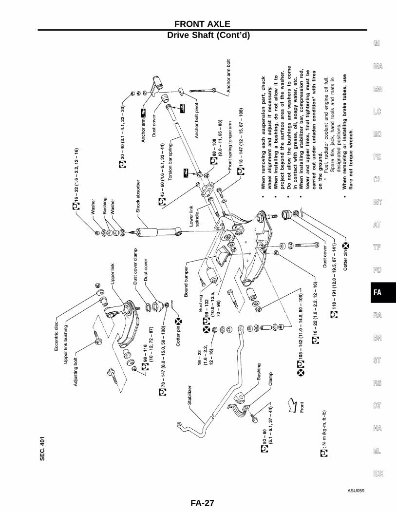
REMOVAL1. Remove free-running hub or drive flange and snap ring. Refer
to ‘‘Auto-lock Free-running Hub’’, FA-15, or ‘‘Manual-lock Free-running Hub’’, FA-14.
2. Remove torsion bar spring. Refer to ‘‘Torsion Bar Spring’’,‘‘FRONT AXLE’’, FA-28.
3. Remove shock absorber lower fixing bolt.4. Remove lower link fixing bolts.Support lower link with jack.
SFA236
5. Remove bolts fixing drive shaft to final drive.
SFA833B
6. Separate drive shaft from knuckle spindle by slightly tappingend of drive shaft.
FRONT AXLE
FA-22

SFA880
DISASSEMBLY
Final drive side (TS82F)1. Remove plug seal from slide joint housing by lightly tapping
around slide joint housing.2. Remove boot bands.
SFA963
3. Move boot and slide joint housing toward wheel side, and putmatching marks.
SFA964
4. Remove snap ring.
SFA392
5. Detach spider assembly with press.
SFA799
6. Draw out boot.Cover drive shaft serration with tape to prevent damaging theboot.
GI
MA
EM
LC
EC
FE
CL
MT
AT
TF
PD
FA
RA
BR
ST
RS
BT
HA
EL
IDX
FRONT AXLEDrive Shaft (Cont’d)
FA-23

SFA455
Wheel side (ZF100)CAUTION:The joint on the wheel side cannot be disassembled.● Before separating joint assembly, put matching marks on drive
shaft and joint assembly.● Separate joint assembly with suitable tool.Be careful not to damage threads on drive shaft.● Remove boot bands.
INSPECTIONThoroughly clean all parts in cleaning solvent, and dry with com-pressed air. Check parts for evidence of deformation and otherdamage.
Drive shaftReplace drive shaft if it is twisted or cracked.
BootCheck boot for fatigue, cracks and wear. Replace boot with newboot bands.
Joint assembly (Final drive side)● Replace any parts of double offset joint which show signs of
scorching, rust, wear or excessive play.● Check serration for deformation. Replace if necessary.● Check slide joint housing for any damage. Replace if neces-
sary.
Joint assembly (Wheel side)Replace joint assembly if it is deformed or damaged.
ASSEMBLY● After drive shaft has been assembled, ensure that it
moves smoothly over its entire range without binding.● Use NISSAN GENUINE GREASE or equivalent after every
overhaul.
SFA800
Final drive side (TS82F)1. Install new small boot band, boot and side joint housing to
drive shaft.Cover drive shaft serration with tape to prevent damagingboot during installation.
FRONT AXLEDrive Shaft (Cont’d)
FA-24

SFA397
2. Install spider assembly securely, making sure marks are prop-erly aligned.
● Press-fit with spider assembly serration chamfer facingshaft.
3. Install new snap ring.
SFA460BA
4. Pack with grease.Specified amount of grease:
95 - 105 g (3.35 - 3.70 oz)5. Make sure that the boot is properly installed on the drive shaft
groove. Set the boot so that it does not swell or deform whenits length is ‘‘L1’’.
Length ‘‘L1’’ : 95 - 97 mm (3.74 - 3.82 in)
SFA443B
6. Lock new large boot band securely with a suitable tool, thenlock new small boot band.
7. Install new plug seal to slide joint housing by lightly tapping it.Apply sealant to mating surface of plug seal.
SFA800
Wheel side (ZF100)1. Install new small boot band and boot on drive shaft.Cover drive shaft serration with tape to prevent damagingboot during installation.
SFA884
2. Set joint assembly onto drive shaft by lightly tapping it.Install joint assembly securely, ensuring that marks which weremade during disassembly are properly aligned.
GI
MA
EM
LC
EC
FE
CL
MT
AT
TF
PD
FA
RA
BR
ST
RS
BT
HA
EL
IDX
FRONT AXLEDrive Shaft (Cont’d)
FA-25

SFA473BA
3. Pack drive shaft with specified amount of grease.Specified amount of grease:
135 - 145 g (4.76 - 5.11 oz)4. Make sure that the boot is properly installed on the drive shaft
groove. Set the boot so that it does not swell or deform whenits length is ‘‘L2’’.
Length ‘‘L2’’ : 96 - 98 mm (3.78 - 3.86 in)5. Lock new large boot band securely with a suitable tool.6. Lock new small boot band.
SFA887
INSTALLATION1. Apply multi-purpose grease.
SFA846
2. Install bearing spacer onto drive shaft.Make sure that the bearing spacer is facing in the proper direc-tion.3. After installing wheel hub and wheel bearing, adjust wheel
bearing preload. Refer to ‘‘PRELOAD ADJUSTMENT’’, ‘‘FrontWheel Bearing’’, ‘‘ON-VEHICLE SERVICE’’, FA-6.
4. When installing drive shaft, adjust drive shaft axial end play byselecting a suitable snap ring.
a. Install fixed cam assembly and spindle washer.b. Temporarily install new snap ring on drive shaft in the same
thickness as it was installed before removal.
LFA016
c. Set dial gauge on drive shaft end.d. Measure axial end play of drive shaft.
Axial end play:0.10 - 0.45 mm (0.004 - 0.0177 in)
e. If axial end play is not within the specified limit, select anothersnap ring.
1.1 mm (0.043 in) 1.3 mm (0.051 in)1.5 mm (0.059 in) 1.7 mm (0.067 in)1.9 mm (0.075 in) 2.1 mm (0.083 in)2.3 mm (0.091 in)
FRONT AXLEDrive Shaft (Cont’d)
FA-26
ASU059
GI
MA
EM
LC
EC
FE
CL
MT
AT
TF
PD
FA
RA
BR
ST
RS
BT
HA
EL
IDX
FRONT AXLEDrive Shaft (Cont’d)
FA-27

SFA836B
Shock Absorber
AFA140
SFA837B
AFA161
REMOVAL AND INSTALLATION1. Support lower link with jack.2. Remove bolt and nut that hold shock absorber.
INSPECTIONExcept for nonmetallic parts, clean all parts with suitable solventand dry with compressed air.Use compressed air to blow dirt and dust off of nonmetallic parts.● Check for oil leakage and cracks. Replace if necessary.● Check piston rod for cracks, deformation and other damage.
Replace if necessary.● Check rubber parts for wear, cracks, damage and deformation.
Replace if necessary.
Torsion Bar SpringREMOVAL1. Move dust cover.2. Paint matching marks on the torsion bar spring and the corre-
sponding arm.Always use paint to place the matching mark; do not scribethe affected parts.3. Measure anchor bolt protrusion ‘‘L’’ and remove the lock nut
and adjusting nut.Before removing the nuts, ensure that twisting force is elimi-nated from the torsion bar springs.
AFA160
4. Remove torsion bar spring.● Remove torque arm fixing nuts, then withdraw torsion bar
spring forward with torque arm.
FRONT AXLE
FA-28

INSPECTION● Check torsion bar spring for wear, twist, bend and other dam-
age.● Check serrations of each part for cracks, wear, twist and other
damage.● Check dust cover for cracks.
SFA549
INSTALLATION AND ADJUSTMENTAdjustment of anchor arm adjusting nut is in tightening direc-tion only.Do not adjust by loosening anchor arm adjusting nut.1. Coat multi-purpose grease on the serration of torsion bar
spring.2. Place lower link in the position where bound bumper clearance
‘‘C’’ is 0.Clearance ‘‘C’’ : 0 mm (0 in)
SFA854
3. Install torsion bar spring with torque arm.Be sure to install right and left torsion bar springs correctly.4. While aligning the anchor arm with the matching mark, install
the anchor arm to the torsion bar spring.If a new torsion bar spring or anchor arm is installed, adjustanchor arm length to the dimension indicated in the figure atthe left.
Standard length ‘‘G’’ :25 - 39 mm (0.98 - 1.54 in)
AFA159
GI
MA
EM
LC
EC
FE
CL
MT
AT
TF
PD
FA
RA
BR
ST
RS
BT
HA
EL
IDX
FRONT AXLETorsion Bar Spring (Cont’d)
FA-29
AFA161
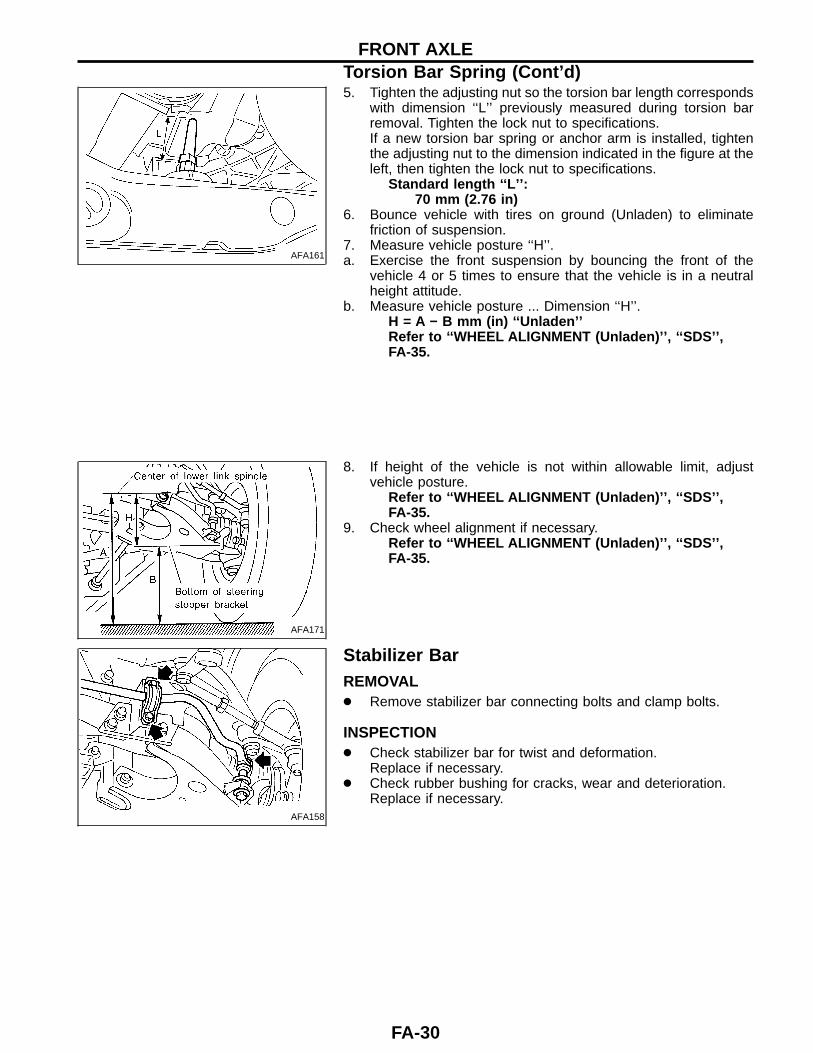
5. Tighten the adjusting nut so the torsion bar length correspondswith dimension ‘‘L’’ previously measured during torsion barremoval. Tighten the lock nut to specifications.If a new torsion bar spring or anchor arm is installed, tightenthe adjusting nut to the dimension indicated in the figure at theleft, then tighten the lock nut to specifications.
Standard length ‘‘L’’ :70 mm (2.76 in)
6. Bounce vehicle with tires on ground (Unladen) to eliminatefriction of suspension.
7. Measure vehicle posture ‘‘H’’.a. Exercise the front suspension by bouncing the front of the
vehicle 4 or 5 times to ensure that the vehicle is in a neutralheight attitude.
b. Measure vehicle posture ... Dimension ‘‘H’’.H = A − B mm (in) ‘‘Unladen’’Refer to ‘‘WHEEL ALIGNMENT (Unladen)’’ , ‘‘SDS’’ ,FA-35.
AFA171
8. If height of the vehicle is not within allowable limit, adjustvehicle posture.
Refer to ‘‘WHEEL ALIGNMENT (Unladen)’’ , ‘‘SDS’’ ,FA-35.
9. Check wheel alignment if necessary.Refer to ‘‘WHEEL ALIGNMENT (Unladen)’’ , ‘‘SDS’’ ,FA-35.
AFA158
Stabilizer BarREMOVAL● Remove stabilizer bar connecting bolts and clamp bolts.
INSPECTION● Check stabilizer bar for twist and deformation.
Replace if necessary.● Check rubber bushing for cracks, wear and deterioration.
Replace if necessary.
FRONT AXLETorsion Bar Spring (Cont’d)
FA-30
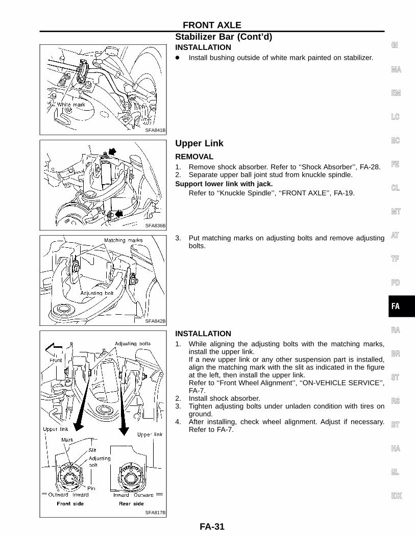
SFA841B
INSTALLATION● Install bushing outside of white mark painted on stabilizer.
SFA836B
Upper LinkREMOVAL1. Remove shock absorber. Refer to ‘‘Shock Absorber’’, FA-28.2. Separate upper ball joint stud from knuckle spindle.Support lower link with jack.
Refer to ‘‘Knuckle Spindle’’, ‘‘FRONT AXLE’’, FA-19.
SFA842B
3. Put matching marks on adjusting bolts and remove adjustingbolts.
SFA817B
INSTALLATION1. While aligning the adjusting bolts with the matching marks,
install the upper link.If a new upper link or any other suspension part is installed,align the matching mark with the slit as indicated in the figureat the left, then install the upper link.Refer to ‘‘Front Wheel Alignment’’, ‘‘ON-VEHICLE SERVICE’’,FA-7.
2. Install shock absorber.3. Tighten adjusting bolts under unladen condition with tires on
ground.4. After installing, check wheel alignment. Adjust if necessary.
Refer to FA-7.
GI
MA
EM
LC
EC
FE
CL
MT
AT
TF
PD
FA
RA
BR
ST
RS
BT
HA
EL
IDX
FRONT AXLEStabilizer Bar (Cont’d)
FA-31

SFA843B
DISASSEMBLY● Press out upper link bushings.
INSPECTION● Check adjusting bolts and rubber bushings for damage.
Replace if necessary.● Check upper link for deformation and cracks. Replace if nec-
essary.
SFA102
ASSEMBLY1. Apply soapsuds to rubber bushing.2. Press upper link bushing.Press bushing so that the flange of bushing securely contactsthe end surface of the upper link collar.
SFA837B
AFA161
Lower LinkREMOVAL AND INSTALLATION1. Remove torsion bar spring. Refer to ‘‘REMOVAL’’, ‘‘Torsion Bar
Spring’’, FA-28.Make matching marks and measure dimension ‘‘L’’ when loos-ening adjusting nut until there is no tension on torsion barspring.2. Remove shock absorber lower fixing bolt.3. Remove stabilizer bar connecting bolt.4. Separate drive shaft from front final drive.
Refer to ‘‘Drive Shaft’’, ‘‘FRONT AXLE’’, FA-22.5. Separate lower link ball joint from knuckle spindle.
Refer to ‘‘Knuckle Spindle’’, ‘‘FRONT AXLE’’, FA-19.
ASU028
6. Remove front lower link fixing bolts.
FRONT AXLEUpper Link (Cont’d)
FA-32
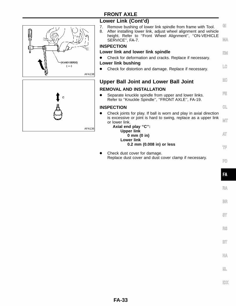
AFA138
7. Remove bushing of lower link spindle from frame with Tool.8. After installing lower link, adjust wheel alignment and vehicle
height. Refer to ‘‘Front Wheel Alignment’’, ‘‘ON-VEHICLESERVICE’’, FA-7.
INSPECTIONLower link and lower link spindle● Check for deformation and cracks. Replace if necessary.Lower link bushing● Check for distortion and damage. Replace if necessary.
AFA136
Upper Ball Joint and Lower Ball JointREMOVAL AND INSTALLATION● Separate knuckle spindle from upper and lower links.
Refer to ‘‘Knuckle Spindle’’, ‘‘FRONT AXLE’’, FA-19.
INSPECTION● Check joints for play. If ball is worn and play in axial direction
is excessive or joint is hard to swing, replace as a upper linkor lower link.
Axial end play ‘‘C’’ :Upper link
0 mm (0 in)Lower link
0.2 mm (0.008 in) or less
● Check dust cover for damage.Replace dust cover and dust cover clamp if necessary.
GI
MA
EM
LC
EC
FE
CL
MT
AT
TF
PD
FA
RA
BR
ST
RS
BT
HA
EL
IDX
FRONT AXLELower Link (Cont’d)
FA-33
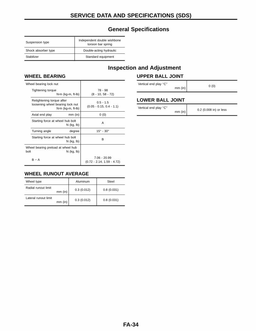
General Specifications
Suspension typeIndependent double wishbone
torsion bar spring
Shock absorber type Double-acting hydraulic
Stabilizer Standard equipment
Inspection and AdjustmentWHEEL BEARING
Wheel bearing lock nut
Tightening torqueN�m (kg-m, ft-lb)
78 - 98(8 - 10, 58 - 72)
Retightening torque afterloosening wheel bearing lock nut
N�m (kg-m, ft-lb)
0.5 - 1.5(0.05 - 0.15, 0.4 - 1.1)
Axial end play mm (in) 0 (0)
Starting force at wheel hub boltN (kg, lb)
A
Turning angle degree 15° - 30°
Starting force at wheel hub boltN (kg, lb)
B
Wheel bearing preload at wheel hubbolt N (kg, lb)
B − A7.06 - 20.99
(0.72 - 2.14, 1.59 - 4.72)
WHEEL RUNOUT AVERAGE
Wheel type Aluminum Steel
Radial runout limitmm (in)
0.3 (0.012) 0.8 (0.031)
Lateral runout limitmm (in)
0.3 (0.012) 0.8 (0.031)
UPPER BALL JOINT
Vertical end play ‘‘C’’mm (in)
0 (0)
LOWER BALL JOINT
Vertical end play ‘‘C’’mm (in)
0.2 (0.008 in) or less
SERVICE DATA AND SPECIFICATIONS (SDS)
FA-34
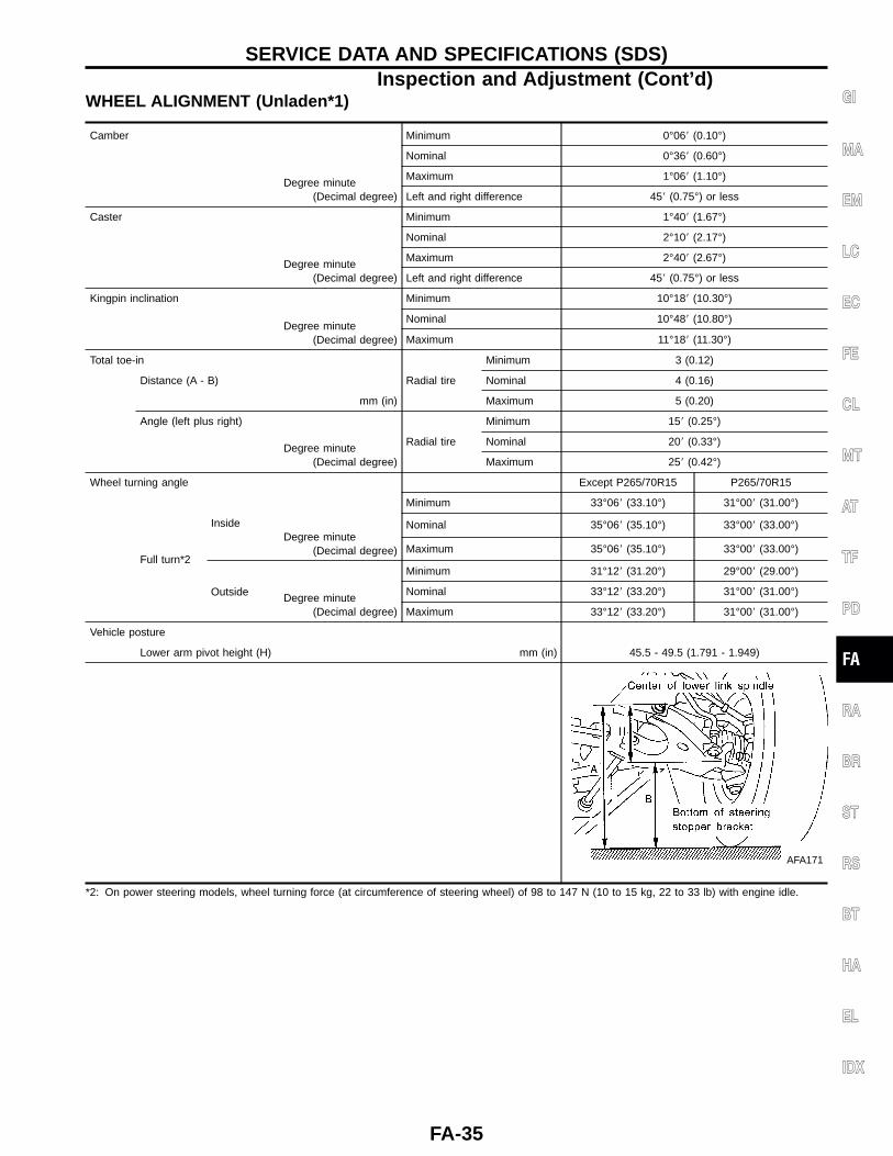
WHEEL ALIGNMENT (Unladen*1)
Camber Minimum 0°06� (0.10°)
Degree minute(Decimal degree)
Nominal 0°36� (0.60°)
Maximum 1°06� (1.10°)
Left and right difference 45� (0.75°) or less
Caster Minimum 1°40� (1.67°)
Degree minute(Decimal degree)
Nominal 2°10� (2.17°)
Maximum 2°40� (2.67°)
Left and right difference 45� (0.75°) or less
Kingpin inclination Minimum 10°18� (10.30°)
Degree minute(Decimal degree)
Nominal 10°48� (10.80°)
Maximum 11°18� (11.30°)
Total toe-in
Radial tire
Minimum 3 (0.12)
Distance (A - B) Nominal 4 (0.16)
mm (in) Maximum 5 (0.20)
Angle (left plus right)
Degree minute(Decimal degree)
Radial tire
Minimum 15� (0.25°)
Nominal 20� (0.33°)
Maximum 25� (0.42°)
Wheel turning angle Except P265/70R15 P265/70R15
Minimum 33°06� (33.10°) 31°00� (31.00°)
Full turn*2
InsideDegree minute
(Decimal degree)
Nominal 35°06� (35.10°) 33°00� (33.00°)
Maximum 35°06� (35.10°) 33°00� (33.00°)
Outside
Minimum 31°12� (31.20°) 29°00� (29.00°)
Degree minute(Decimal degree)
Nominal 33°12� (33.20°) 31°00� (31.00°)
Maximum 33°12� (33.20°) 31°00� (31.00°)
Vehicle posture
Lower arm pivot height (H) mm (in) 45.5 - 49.5 (1.791 - 1.949)
AFA171
*2: On power steering models, wheel turning force (at circumference of steering wheel) of 98 to 147 N (10 to 15 kg, 22 to 33 lb) with engine idle.
GI
MA
EM
LC
EC
FE
CL
MT
AT
TF
PD
FA
RA
BR
ST
RS
BT
HA
EL
IDX
SERVICE DATA AND SPECIFICATIONS (SDS)Inspection and Adjustment (Cont’d)
FA-35
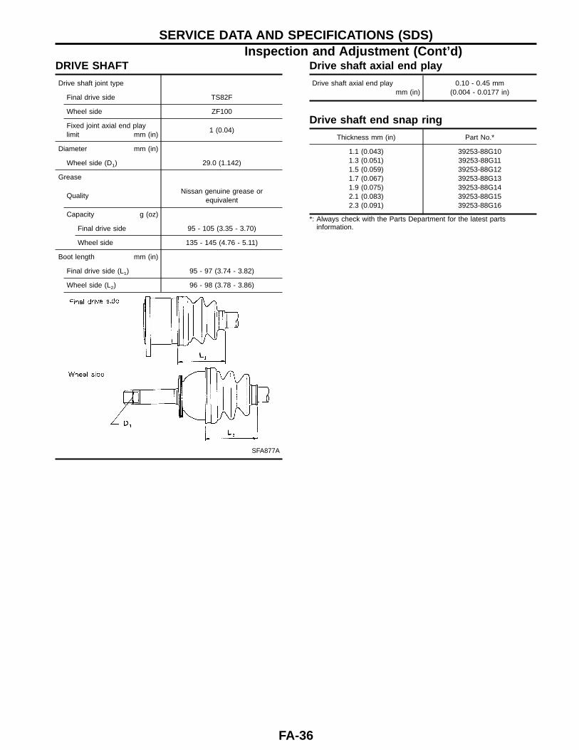
DRIVE SHAFT
Drive shaft joint type
Final drive side TS82F
Wheel side ZF100
Fixed joint axial end playlimit mm (in)
1 (0.04)
Diameter mm (in)
Wheel side (D1) 29.0 (1.142)
Grease
QualityNissan genuine grease or
equivalent
Capacity g (oz)
Final drive side 95 - 105 (3.35 - 3.70)
Wheel side 135 - 145 (4.76 - 5.11)
Boot length mm (in)
Final drive side (L1) 95 - 97 (3.74 - 3.82)
Wheel side (L2) 96 - 98 (3.78 - 3.86)
SFA877A
Drive shaft axial end play
Drive shaft axial end playmm (in)
0.10 - 0.45 mm(0.004 - 0.0177 in)
Drive shaft end snap ring
Thickness mm (in) Part No.*
1.1 (0.043)1.3 (0.051)1.5 (0.059)1.7 (0.067)1.9 (0.075)2.1 (0.083)2.3 (0.091)
39253-88G1039253-88G1139253-88G1239253-88G1339253-88G1439253-88G1539253-88G16
*: Always check with the Parts Department for the latest partsinformation.
SERVICE DATA AND SPECIFICATIONS (SDS)Inspection and Adjustment (Cont’d)
FA-36