Embed Size (px)
Citation preview

A Boundary Element Approach for
Initial Receding Contact Problem involving
Large Displacements
J.A. Garrido and A. Lorenzana
Department of Strength of Materials and Structures, E. T. S. I. L,
EMail: [email protected]
Abstract
An algorithm based on the Boundary Element Method is utilised for the frictionless and fric-tional loading process in the specific case of receding contact problem. The formulation islimited to elastic behaviour of the materials involved and a Coulomb Type of friction is as-sumed. The contact constraints are applied node on element using quadratic shape functions todistribute the geometry, tractions and displacements at the contact zone. Therefore, the usualway of imposing the contact conditions (node-pair) is abandoned. That allows us to deal withthe large displacement problem using an incremental procedure (Updated Lagrangian Ap-proach). At least one increment of load must be done for each node changing its contact con-dition and additional increments could be necessary to note any relevant alterations of thegeometry. The algorithm guarantees compatibility and equilibrium at the nodes in the finaldeformed configuration and special attention is devoted to the frictional effect. The proposedprocedure is applied to the most representative two-dimensional receding contact problem- alayer pressed against an elastic foundation. The results obtained, when the displacements aresmall and friction is not considered, are in good agreement with the analytical solution. Whenfriction is taken into account and large displacements appear, the problem is highly non-linearand the influence of those non-linearities is going to be shown.
1 Introduction
A contact problem occurs when not mechanically joined bodies touch each otherwithout becoming rigidly attached. In several cases, high stress concentrations aredeveloped in the contact areas. This fact and the presence of friction and wear oftencause crack initiation and fretting fatigue. Although in most contact problems thecontact zone increases after application of the load, there are others where the final
Transactions on Engineering Sciences vol 14, © 1997 WIT Press, www.witpress.com, ISSN 1743-3533

82 Contact Mechanics HI
contact zone is smaller than the original. This kind of problem is referred to by thegeneric name of receding contact.Despite the great effort made in the analytical study of contact problems
(Gladwell), the solutions are only available for idealised models and their applica-tion to practical problems is obviously limited. Hertz obtained the solution for theso called hertzian problems and Keer, Dundurs and Tsai presented the solution forthe receding case investigated in this paper: an elastic layer pressed against halfspace. Both studies only considered the frictionless case undergoing infinitesimaldisplacements. For the general study, it is necessary to develop numerical tech-niques based on the Finite Element Method (FEM) or on the Boundary ElementMethod (BEM), capable of handling arbitrary geometries and including frictionaleffects at the interface, plasticity, large displacements, large strains, etc.Most of these techniques require, in order to apply the contact conditions be-
tween corresponding nodes, a matching partition of each body into elements andnodes at the contact zone. First works with this aim are the ones presented by Chanand Tuba"*, Francavilla and Zienkievicz*, etc. using the FEM, followed by the pa-pers of Anderson and Garrido et al using the BEM. In the present paper this re-straint is removed and one node-on-element contact algorithm based on the BEM isset. This method is probably the most appropriate for the problem under study,where domain forces lack importance and where only the variables associated tothe boundary (tractions and displacements) are involved. Thus, computational timeis saved, an important fact when solving problems of incremental or iterative na-ture. The algorithm uses a length mapping procedure to place the appropriate pointwhich a node is in contact with at the final configuration of each increment. Thesolution is obtained through a system of equations of fixed size, depending on thetotal number of nodes. Each increment of load is determined by two possible mo-tives: either a node changes any of its boundary conditions or the geometry hassuffered substantial modifications that force us to compute again the matrices in-volved.Some algorithms have already been used removing the node-on-node require-
ment, not only by means of the FEM (Bathe and Chaudhary , Kodikara and Moore*and Klarbring and Bjorkman*) but also with the BEM (Olukoko et o/.*°, Paris etal and Chen and Chen ). The next sections establish the most relevant aspect ofthe proposed algorithm and in the last section the receding problem is analyzedwith this technique, showing the applicability and reliability of the method and themost interesting peculiarities of the large displacements problem.
2 Boundary formulation
Before developing a method for the analysis of the interaction of two bodies, theBEM is reviewed briefly. It is known (Ref. [13]) that one appropriate formulationfor the static analysis of tractions and displacements in a solid body under homoge-neous, isotropic and linear elastic behaviour, assuming the hypothesis of smallstrains and in the absence of body forces, can be done by means of integral equa-
Transactions on Engineering Sciences vol 14, © 1997 WIT Press, www.witpress.com, ISSN 1743-3533
Contact Mechanics HI S3
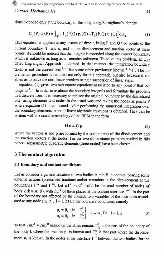
tions extended only at the boundary of the body using Somigliana's identity
u,(P) = ^ U y(P,Q) p,(Q)-Ty(P,Q) u,(Q) dSq (1)
This equation is applied at any instant of time t, being P and Q two points of the
current boundary *F and U; and p; the displacement and traction vector at thesepoints. It should be noticed that the integral is extended along the current boundary,which is unknown as long as U; remains unknown. To solve this problem, an Up-dated Lagrangian Approach is adopted. In that manner, the integration boundary
taken is not the current one 'F, but some other previously known '~ F . The in-cremental procedure is required not only for this approach, but also because it en-ables us to solve the non-linear problem using a succession of linear steps.Equation (1) gives two subsequent equations associated to any point P that be-
longs to *F . In order to evaluate the boundary integrals and formulate the problemin a discrete form it is necessary to replace the original boundary by the discretizedone, using elements and nodes in the usual way and taking the nodes as points Pwhere equation (1) is collocated. After performing the numerical integration overthe boundary elements, a set of linear algebraic equations is obtained. They can bewritten with the usual terminology of the BEM in the form
H u = G p (2)
where the vectors u and p are formed by the components of the displacement andthe traction vectors at the nodes. For the two-dimensional problem studied in thispaper, isoparametric quadratic elements (three-noded) have been chosen.
3 The contact algorithm
3.1 Boundary and contact conditions.
Let us consider a general situation of two bodies A and Bin contact, bearing someexternal actions (prescribed tractions and/or restraints in the displacement at the
boundaries F* and F®). Let nT* = nC* +nL* be the total number of nodes of
body k (k = A, B), with nC of them placed at the contact interface F . In the partof the boundary not affected by the contact, two variables of the four ones associ-ated to any node (u;,p;, i = 1,2) are the boundary conditions, namely
in= A,B; i = l,2 (3)
so that 2nL* 4- 2nL^ unknown variables remain. F is the part of the boundary of
the body k where the traction p; is known and F* is that part where the displace-
ment U; is known. In the nodes at the interface F between the two bodies, for the
Transactions on Engineering Sciences vol 14, © 1997 WIT Press, www.witpress.com, ISSN 1743-3533

Contact Mechanics HI
friction contact problem under study, none of the four variables associated to each
node are known and in order to determine these 4nC^ + 4nC® variables it is neces-sary to utilize the contact conditions that will be established next.
Equation (2), applied in incremental form to each body, provides 2nT* +2nT®equations that can be expressed in a unique system of equations
HA i 0 Au'
0 I H" Au*
j 0 Ap'
0 I G*flAp°(4)
(5)
If the discretizations performed on both bodies in the contact region (initially incontact or expected to come into contact) is matching so that the contact is justbetween nodes, the contact constraints can be imposed affecting only the variablesof the system of equations (4), being in this case immediate their application. Oth-erwise, one node (m) of one of the bodies (master body M) will come into contactat a certain point (s) of an element of the other body (slave body S). The point s isdetermined by its corresponding intrinsic coordinate £ within the element to whichs belongs (see Ref. [14]). The contact constraints, enforcing equilibrium and com-patibility between node m and point s, are imposed by means of
mPi^O. (b)
ImPll^MlmPlI (4
mPl(mUl+sUl) = 0. (d)
the subindices 1 and 2 affect the normal and tangential direction respectively. Eqn(5.a) sets the equilibrium condition. Eqn. (5.b) imposes a positive contact pressure.Eqn. (5.c) is the Coulomb friction law that establishes that the tangential traction atany node at the interface is less than the product of the normal traction at that nodeand the constant coefficient of friction ja (in adhesion state), which is representativeof the material and the surface or (in slip state) equal to that value with a sign thatagrees with (5.f). Eqn. (5.d) shows that any node is either in contact (being^AUj+,.AUi =0. the compatibility equation in the normal direction) or free ofcontact (n,p, = 0.). Eqn. (5.e) establishes that if in contact it is either in stick state(being 2+5 2 = 0. the compatibility equation in the tangential direction) or in slip
state (|n,P2|~M-|mPi| ~ 0.), being Au2+<.Au2 * 0. the relative slip. The limit of theapplicability of the sliding condition is caused by the fact that sliding causes dissi-pation of energy, eqn. (5.f), which gives the friction phenomenon an irreversiblecharacter. Therefore the whole load history can only be properly followed using theincremental technique, already demanded by the updated lagrangian approachadopted. The sign of the tangential traction is unknown a priori. It has to be as-
Transactions on Engineering Sciences vol 14, © 1997 WIT Press, www.witpress.com, ISSN 1743-3533
Contact Mechanics III &5
signed, so that the resultant Motional traction always opposes the relative slip in thecontact region.
3.2 The general solution procedure
The contact constraints are included in the system of equations (4) in an implicitmanner. Once is known, Au. and ,Ap; (i= 1,2) could be expressed, using theshape functions, in function of the corresponding displacement and traction com-ponents at the nodes si, s2 and s3 of the element to which point s belongs. Thus,the tractions and/or the displacements of each node m in the contact zone can bethen related by the equations (5) with the tractions and/or displacements of thenodes si, s2 and s3 and this traction and/or displacement does no appear in equa-
tion (4). This process must be done for every node at T that belongs either to bodyA or B, but if the displacements of the nodes of body A are expressed as functionsof those at body B, the tractions at the nodes of body B must be expresed as func-tions of those at the nodes of body A. The friction conditions are imposed on the
body that controls the tractions. Thus, in stick mode 2nC* unknowns on tractions
and 2nC® on displacements come out of the equation system (or vice-versa had thechoice been the opposite) and, in the slip mode the variables that do not take part
are 2nC* unknowns on tractions and nC® on displacements (tangential displace-
ment) and nC® on tractions (normal traction). Therefore, the number of unknownsagrees with the number of equations.
When the contact zone is not known since it depends on the applied load P, anincremental procedure is performed so that the nodes out of the initial contact zoneare introduced into it or the nodes inside the initial contact zone abandon it. Inter-penetration at the nodes between the bodies is prevented by the construction of thealgorithm itself and the procedure to find out the fraction of load A, that makes anew node (of one of both bodies) to come into contact is explained in Ref.[13].
It might be necessary to check if any positive traction (not compression) appearsat the nodes of the contact zone after the application of each increment of load. Inorder to avoid that incompatibility, these nodes must be taken outside the contactzone. The process is incremental for each node and the load parameter A, that
makes p, =0.,and then the separation of node m occurs, is determined by
t-At
where Pi is the contact pressure at the node m which is going to separate andmAPi is the traction that appears at the same node when load P is applied.Frictional contacts are either sticking or sliding. The length of these two different
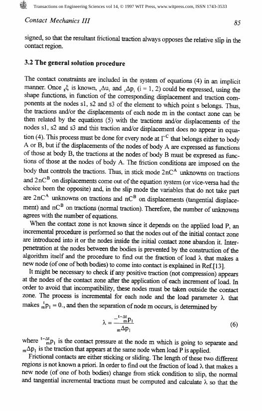
regions is not known a priori. In order to find out the fraction of load X that makes anew node (of one of both bodies) change from stick condition to slip, the normaland tangential incremental tractions must be computed and calculate A, so that the
Transactions on Engineering Sciences vol 14, © 1997 WIT Press, www.witpress.com, ISSN 1743-3533
Contact Mechanics HI
accumulated contact traction at time t satisfies Coulomb's law, namely
= 0. (7)
The opposite case, the change from slip to stick condition, necessary when the dis-sipating criterion (5.f) is not satisfied in one node, is not scalable. In this case, thefriction state of this node is changed, being 1 = 0.0, and the following increment isdealt with next.
At this stage, it is also necessary to check whether, for the incremental load ob-tained X, the maximum accumulated nodal displacement since the last geometryupdating is below the admissible 5 , in order to ensure the hypothesis on whichthe Updated Lagrangian Approach is based. If that is not the case, the application ofthe whole incremental load 1 will not be possible, being therefore necessary toupdate the geometry.There are cases in which the tangential traction of the node where the slip zone
begins, despite being in slip condition, if the node does not belong to the body thatgoverns the tractions, might not be exactly the same as its normal traction multi-plied by the friction coefficient but very slightly smaller, since its tangential tractionis interpolated in function of others in stick condition. In these cases the generalalgorithm must be allowed to continue, as the error is very small.
4 Application
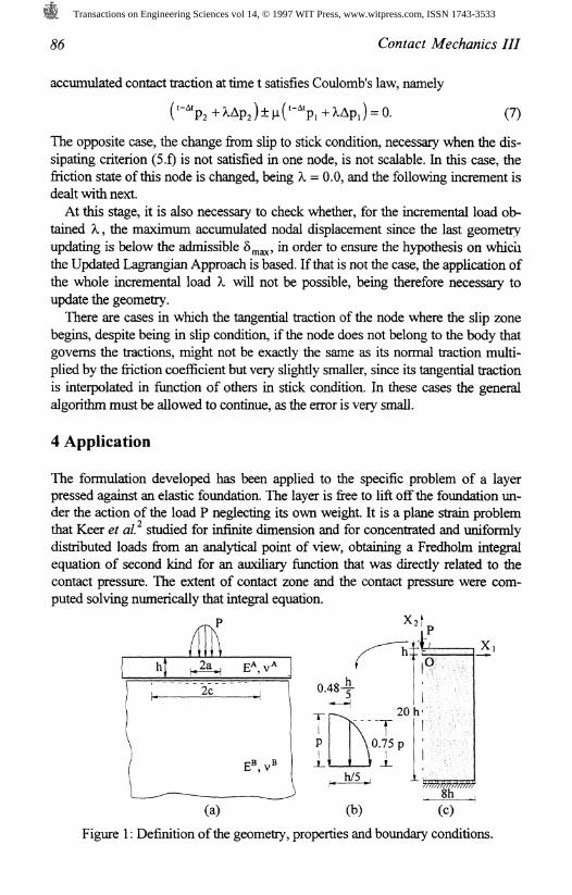
The formulation developed has been applied to the specific problem of a layerpressed against an elastic foundation. The layer is free to lift off the foundation un-der the action of the load P neglecting its own weight It is a plane strain problemthat Keer et al studied for infinite dimension and for concentrated and uniformlydistributed loads from an analytical point of view, obtaining a Fredholm integralequation of second kind for an auxiliary function that was directly related to thecontact pressure. The extent of contact zone and the contact pressure were com-puted solving numerically that integral equation.
2c
(a) (c)
Figure 1: Definition of the geometry, properties and boundary conditions.
Transactions on Engineering Sciences vol 14, © 1997 WIT Press, www.witpress.com, ISSN 1743-3533

Contact Mechanics III 87
Even for the analytical cases studied, when finite dimension is involved, the prob-lem leads to the need of numerical methods of analysis. From this numerical pointof view, there are hardly any studies related to the receding contact problem. Gar-rido et al* analysed almost the same problem (but not in infinite dimension) usingboundary elements.
Figure 1 represents the geometry, the boundary conditions and the properties of
both bodies, being E* Young's modulus of body k and v* Poisson's ratio. For thiskind of contact problems, when displacements are infinitesimal, the study of Keeret al showed that the length of contact changes discontinuosly from its initialshape (unloaded) to its loaded one and if the load increases in magnitude, but doesnot change in disposition, the contact area does not change, although the displace-ments, strains and stresses increase in direct proportion to the load. Therefore, un-der these assumptions, once the contact area is found, the problem is linear andonly one increment is required for its solution. The final situation depends exclu-sively on the mechanical properties of the materials involved, summarized by Dun-durs' mismatch parameter a. This linear solution is plotted in figure 2 in order tocompare it with the solutions of the problem undergoing large displacements forthe same level of load applied.
Due to the symmetry of the problem, only half of the geometry needs to bemodelled. 44 elements have been employed for body A and for body B. The load isapplied (figure l.(b)) as a pressure distribution along a very small length in com-parison to the minimum contact length, so the result can be compared with thatsupposing concentrated load.
0.4 * (relative slip) 0.08
-0.30(p.= normal traction or tangential traction/ p)
Figure 2: Normal and tangential stresses along the contact zone andrelative tangential displacements along the contact zone.
-0.30
Transactions on Engineering Sciences vol 14, © 1997 WIT Press, www.witpress.com, ISSN 1743-3533

88 Contact Mechanics HI
An increment of load is made each time any node changes its boundary conditionand the geometry is updated each time the displacement 8 of any node exceeds0.25% of the greatest characteristic length of the body it belongs to, being this per-centage established before hand. It has been verified that any percentage lower thanthat does not affect the solution substantially, although a larger number of incre-ments are necessary.
The distribution of the contact stresses along the contact zone is shown in figure2 for a = -0.923 (the layer is far more rigid than the foundation). The fiictionlessresults obtained almost coincide with the solution of reference for the minimumload applied P (being P the load from which geometry updating is necessaryfor the first time since 8 is exceeded in any node). As the load increases and thedisplacements begin to be important compared to the dimension of the bodies, thedistribution of contact pressure begins to differ from the analytical solution, there-fore the problem will be no longer linear. Thus, although the initial semi-length ofthe contact zone c is 3.494 h for the frictionless case and 3.687 h for the frictionalcase, when P = 2920.8 N/mm is applied, the deformed length of contact is ap-proximately 3.59 h for the frictionless case and 3.873 h for the frictional one. Fig-ure 2 shows the distribution for P /2 and for P . The tractions are plotted intheir corresponding deformed configuration and the load has been evaluated by inte-gration of the resultant stress distribution at the contact zone of any of both bodies.
Figure 2 also shows the relative tangential displacements (mjU +sjU ) or slips at
the contact zone. For the frictionless case, it can be observed that as the load in-creases, the slips also increase, but not in a monotonic way. For this case, it hasbeen noted that there is a load value (over P , not shown in the graphic) forwhich the slip is maximum. From then onwards, the slips decrease for every nodeuntil the last contact node, where it is zero, and even the last nodes in contact mightreach a slip whose sign is the opposite of the initial one. This behaviour found un-der large displacements differs radically from the expected (reference problem un-dergoing infinitesimal displacements). We do not include figures since it onlyappears when the loads are very high and, for the frictional case, at these stages ofthe load numerical difficulties have arisen. Therefore an appropriate solution, to becompared with the frictionless case, has not been achieved for the time being.
For the frictional case, as the load increases, so does the length of the stick zonefrom its initial value b, = 0.239 h until b% = 1.123 h for a P /2 load. Beyondthat load, the stick zone increases even more rapidly and for P ^ the entire contactzone is in stick state. That is why the two accumulated slip curves in figure 2 al-most coincide. It must be also noticed that the maximum accumulated slips for thefrictionless case are some three times bigger than those in the frictional case.The deformed configurations for P ^ and P ax/ re shown in figure 3. In-scale
displacements are shown in figure 3(c). Although for both cases analysed the de-formed configurations almost coincide, some differences can be noted, namely, thedeformed configuration of the layer in the frictionless case is, in the central region,lower and, in the ends, higher than that corresponding to the frictional case. The di-
Transactions on Engineering Sciences vol 14, © 1997 WIT Press, www.witpress.com, ISSN 1743-3533

Contact Mechanics HI #9
rection of sliping for both cases (p, = 0.0 and p. = 0.25) can be seen also in figures3(a) and 3(b). Note that for the frictional case, although for P every node is in stickcondition, those father away from the central zone have accumulated a non zero slip.
Stick
Figure 3: Deformed configurations at the contact zone.
5 Conclusions
An incremental procedure for two-dimensional frictional contact problems, understatic and proportional loading conditions, with the possibility of large displace-ments has been presented. The node-on-element algorithm of contact has been im-plemented using the boundary element techniques, probably the most appropriatefor this kind of problems, where the magnitudes of interest are on the boundary,where domain loads usually do not appear and where the solution procedure is in-cremental due not only to large displacements, but also to frictional effects.The method has shown its reliability when the displacements are small, reaching
numerical results in good agreement with those obtained by other authors. Thethree-noded isoparametric elements utilized in the discretization are suitable for the
Transactions on Engineering Sciences vol 14, © 1997 WIT Press, www.witpress.com, ISSN 1743-3533

90 Contact Mechanics III
example analysed. No incompatibilities whatsoever have appeared at the nodes andno other specific procedures have been necessary. With this type of elements thealgorithm guarantees compatibility (no interpenetrations) at the nodes and equilib-rium (same distribution of contact stress) along the contact zone.The method has a very large field of application, but a future extension to some
aspects like dealing not only with advancing contact but also receding contact, in-clusion of large strain theory, possibility of plastic zones, three-dimensional contactproblems, etc., is necessary.
Keywords:Boundary Element, Receding Contact Problem, Large Displacement, Friction.
References
1. Gladwell G.M.L. Contact Problems in the Classical Theory of Elasticity. Sijthoff& Noordhoff, Ontario (1980).
2. Keer L.M., Dundurs J. and Tsai K.C. Problems involving a receding contactbetween a layer and half space. J. Applied Mech. 39,1115-1120 (1972).
3. S. K. Chan and I. S. Tuba, A finite element method for contact problems of solidbodies-1. Theory and Validation. Int. J. of meek Sci. 13, 615-625 (1971).
4. A. Francavilla and O. C. Zienkiewicz, A note on numerical computation of elas-tic contact problems, Int. J. numer. Meth Engng 17, 913-924 (1975).
5. T. Anderson, The boundary element method applied to 2D-contact problemswith friction, In: Boundary Element Methods, 239-258, Springer, Berlin (1982).
6. J. A. Garrido, A. Foces and F. Paris, B.E.M. applied to receding contact prob-lems with friction, Math Comput. Modell 15,143-154(1991).
7. K. J. Bathe and A. Chaudhary, A solution method for planar and axisymmetriccontact problems, Int. J. numer. Meth. Engng 21, 65-88 (1985).
8. J. K. Kodikara and I. D. Moore. A general interaction analysis for large defor-mations, Int. J. numer. Meth. Engng 36, 2863-2876 (1993).
9. A. Klarbring and G. Bjorkman. Solution of large displacement contact problemswith friction using Newton's method for generalized equations, Int. J. Num.Meth. Engng, 34,249-269 (1992).
10. O. A. Olukoko, A. Becker and R. T. Fenner. A new boundary element apprachfor contact problems with friction, Int. J. N. Meth. Engng 36,2625-2642 (1993).
11.1% Paris, A. Blazquez and J. Canas. Contact problems with nonconforming dis-cretizations using boundary element method, Comput. Struct. 57,829-839 (1995).
12. W. H. Chen and T. C. Cheng, Boundary element analysis for contact problemswith friction. Comput. Struct. 45,431-438 (1992).
13. C.A. Brebbia, J.C.F. Telles & L.C. Wrobel, Boundary Element Techniques.Theory and Applications in Engineering. Springer-Verlag. Berlin (1984)
14. A. Lorenzana, J.A. Garrido and I. Prieto, A boundary element approach forcontact problems involving large displacements. In: Boundary Element Tech-nology XI, pp 203-212, CMP, Southampton (1996).
Transactions on Engineering Sciences vol 14, © 1997 WIT Press, www.witpress.com, ISSN 1743-3533