Embed Size (px)
Citation preview

EMC Performance Protocol Testing Enabled by EMC Celerra, and the
iSCSI and NFS Protocols Applied Technology
Abstract
As the use of virtualized data centers in the private cloud continues to expand, the physical connections between servers and SAN storage resources become more critical. Our testing shows that using link aggregation in storage subnets for NFS and iSCSI datastores helps data center managers reduce costs, increase efficiency, and safeguard the availability of resources and applications.
November 2009

EMC Performance Protocol Testing Enabled by EMC Celerra, and the iSCSI and NFS Protocols Applied Technology 2
Copyright © 2009 EMC Corporation. All rights reserved.
EMC believes the information in this publication is accurate as of its publication date. The information is subject to change without notice.
THE INFORMATION IN THIS PUBLICATION IS PROVIDED “AS IS.” EMC CORPORATION MAKES NO REPRESENTATIONS OR WARRANTIES OF ANY KIND WITH RESPECT TO THE INFORMATION IN THIS PUBLICATION, AND SPECIFICALLY DISCLAIMS IMPLIED WARRANTIES OF MERCHANTABILITY OR FITNESS FOR A PARTICULAR PURPOSE.
Use, copying, and distribution of any EMC software described in this publication requires an applicable software license.
For the most up-to-date listing of EMC product names, see EMC Corporation Trademarks on EMC.com
All other trademarks used herein are the property of their respective owners.
Part number: H6724

EMC Performance Protocol Testing Enabled by EMC Celerra, and the iSCSI and NFS Protocols Applied Technology 3
Table of Contents
Executive summary ........................................................................................................................... 4 Introduction ........................................................................................................................................ 5 Multipath performance analysis ........................................................................................................ 6 Key components ............................................................................................................................... 7 Physical architecture ......................................................................................................................... 8 Environment profile ........................................................................................................................... 9 Test design and validation .............................................................................................................. 11 NFS datastore — link aggregation .................................................................................................. 12 NFS datastore — no link aggregation ............................................................................................. 15 NFS performance results ................................................................................................................ 18 NFS datastore troubleshooting ....................................................................................................... 19 iSCSI datastore – link aggregation.................................................................................................. 25 iSCSI datastore – No link aggregation ............................................................................................ 29 iSCSI performance results .............................................................................................................. 32 iSCSI datastore troubleshooting ..................................................................................................... 33 Performance analysis ...................................................................................................................... 36 Conclusion ....................................................................................................................................... 40

EMC Performance Protocol Testing Enabled by EMC Celerra, and the iSCSI and NFS Protocols Applied Technology 4
Executive summary
Business case Data center managers are looking to virtualization as a means to
• reduce costs, • increase efficiency, and • deliver the service levels they require. In a virtualized data center, physical server consolidation results in • reclaiming valuable data center space, • realizing higher use rates, • increasing operational efficiencies, and • improving availability of resources and applications. As virtualized data centers expand, the physical connections between the servers and SAN storage resources become more critical.
Product solution
EMC® Celerra® can meet an organization’s data storage needs with a wide range of supported storage protocols including: • NAS (including NFS and CIS) • iSCSI • Fibre Channel NFS and iSCSI become the protocols of choice when using Ethernet resources.
Key results Our testing showed the effects of using link aggregation in single and multiple
storage subnets for NFS and iSCSI datastores.

EMC Performance Protocol Testing Enabled by EMC Celerra, and the iSCSI and NFS Protocols Applied Technology 5
Introduction
Purpose This Applied Technology white paper can assist you in planning a vSphere
environment on EMC Celerra technology to take advantage of the high-availability features of NFS or iSCSI datastores. These environments include:
Link aggregation • Single storage subnet • Two storage subnets
Without link aggregation • Single storage subnet • Two storage subnets
Audience This white paper is intended for EMC employees, partners, and customers including
IT planners, virtualization architects and administrators, and any other IT professionals involved in evaluating, acquiring, managing, operating, or designing a private cloud environment leveraging EMC technologies.

EMC Performance Protocol Testing Enabled by EMC Celerra, and the iSCSI and NFS Protocols Applied Technology 6
Multipath performance analysis
Introduction To ensure maximum resource availability, a data center infrastructure must
• Provide multiple physical data paths between the server and the storage resources • Allow path rerouting around problems such as failed components • Balance the traffic loads across multiple physical paths
Multipathing To maintain a constant connection between a virtualized server host and its storage,
a technique called multipathing is used. Multipathing maintains more than one physical path for data between the host and the storage device. If any element in the SAN fails such as an adapter, switch, or cable, the virtualized server host can switch to another physical path that does not use the failed component. The process of path switching to avoid failed components is known as path failover.
Load balancing In addition to path failover, multipathing provides load balancing. Load balancing is
the process of distributing loads across multiple physical paths to reduce or remove potential I/O traffic bottlenecks.

EMC Performance Protocol Testing Enabled by EMC Celerra, and the iSCSI and NFS Protocols Applied Technology 7
Key components
Introduction For the high-availability scenario described in this white paper, NFS and iSCSI
datastores are deployed in a virtualized data center that includes: • Three VMware vSphere ESX 4 servers (user hosts) • Cisco Catalyst 3750-E Ethernet switches • EMC Celerra NS-120 • I/O simulation software
Cisco Catalyst 3750E
Cisco Catalyst 3750 is an energy-efficient, Layer 3, faster Gigabit Ethernet, stackable switch. Cisco Catalyst switches uses StackWise technology that unites up to nine individual switches into a single logical unit using special stack interconnect cables and stacking software.
EMC Celerra NS-120
EMC Celerra NS-120 is an affordable unified storage system that scales to 120 drives. With Celerra NS-120, you can connect to multiple storage networks via network-attached storage (NAS), iSCSI, Fibre Channel SAN, and Celerra Multi-Path File System (MPFS).
vSphere 4 VMware vSphere 4 is the next logical step in IT computing, allowing customers to
bring the power of cloud computing to their IT infrastructures. Building on the power of VMware Infrastructure, VMware vSphere 4 increases control over IT environments by supporting many OS, application, and hardware products. VMware vSphere 4 is built on a proven virtualization platform to provide the foundation for internal and external clouds, using federation and standards to bridge cloud infrastructures—creating a secure, private cloud. Organizations of all sizes can achieve the full benefits of cloud computing, delivering the highest levels of application service agreements with the lowest total cost per application workload. This data center solution delivers flexible, automatic I/O load balancing, powerful processing power, and simplified network switch management with these features introduced in VMware vSphere 4: • EMC PowerPath®/VE path failover integration (via VMware vStorage API for
Multipathing)—As demonstrated in this solution, PowerPath/VE constantly adjusts I/O path usage and responds to changes in I/O loads from VMs.
• 8 vCPU support—Increases the maximum number of virtual CPUs that can be assigned to a guest VM from four to eight.
• VMware vNetwork Distributed Switch—Takes the vSwitch capability one step further by extending the connections across the entire cluster.
I/O simulation software
The following load simulation software is used: • IOMeter 2006.07.27

EMC Performance Protocol Testing Enabled by EMC Celerra, and the iSCSI and NFS Protocols Applied Technology 8
Physical architecture
Architecture diagram
The following illustration depicts the overall physical architecture of the test environment. Two NICs on each server are used for either NFS or iSCSI connection based on the test case. The virtual machines are running IOMeter Dynamo with IOMeter master running on the vCenter server. Each IOMeter Dynamo VM has one data disk hosted on its own iSCSI or NFS datastore. The OS disks are hosted on a shared datastore.

EMC Performance Protocol Testing Enabled by EMC Celerra, and the iSCSI and NFS Protocols Applied Technology 9
Environment profile
Hardware resources
The hardware used in the performance analysis environment is listed in the following table.
Equipment Quantity Configuration
EMC Celerra NS-120 running DART 5.6.46
1 Nine file systems • One 510 GB file system containing: − 1 x 498 GB iSCSI LUN
• Eight 537 GB file systems containing: − 1 x 268 GB iSCSI LUN per file system − 1 x NFS export per file system
Dell 2950 3 2 x Intel Xeon 4 Core (54xx) 32 GB RAM 2 x Intel 82575GB Quad Gigabit Ethernet NIC
Ethernet switch 2 Cisco Catalyst 3750-E
Virtual allocation of hardware resources
The following table shows the virtual machine allocation.
Virtual Machine Resource
vCenter 2 vCPUs 4 GB RAM 20 GB HDD (LSI Logic SCSI Controller) 1 virtual NIC
DC 2 vCPUs 4 GB RAM 20 GB HDD (LSI Logic SCSI Controller) 1 virtual NIC
VM1 to VM8 1 vCPU 1 GB RAM 20 GB HDD (LSI Logic SCSI Controller) 100 GB HDD (Paravirtualized SCSI Controller) 1 virtual NIC

EMC Performance Protocol Testing Enabled by EMC Celerra, and the iSCSI and NFS Protocols Applied Technology 10
Software resources
The software that we used in the performance analysis environment is listed below.
Software Version
vSphere Enterprise Plus 4.0 (build 164009)
vCenter 4.0 GA (build B162856)
PowerPath/VE 5.4 (build 257)
IOMeter 2006.07.27
Dynamo 2006.07.27

EMC Performance Protocol Testing Enabled by EMC Celerra, and the iSCSI and NFS Protocols Applied Technology 11
Test design and validation
Introduction This section outlines the test plan and implementation for the test environment used
for this white paper.
Test plan • Create and deploy eight virtual machines running Windows 2003
− Four VMs on one server − Four VMs on a second server
• Use a Paravirtual SCSI driver to access the data disks • Create a 100 GB data disk on a iSCSI or NFS datastore based on the test case • The data disk partition aligned to 64k • Have IOMeter Dynamo running on all eights VMs • Use vCenter server as IOMeter Master • Use IOMeter Access specification of 8K, 50% Write, 50% Random for all test
cases • Use Jumbo frames on the storage network • Use flow control on the storage network • Share the same file system for iSCSI and NFS for these test cases
Test parameters
Our test will explore the details of implementation of datastore to the following scenarios and compares the IOMeter test results.
NFS datastore • Link aggregation − Single storage subnet − Two storage subnets
• Without link aggregation − Single storage subnet − Two storage subnets
iSCSI datastore • Link aggregation − Single storage subnet − Two storage subnets
• Without link aggregation − Single storage subnet − Two storage subnets

EMC Performance Protocol Testing Enabled by EMC Celerra, and the iSCSI and NFS Protocols Applied Technology 12
NFS datastore — link aggregation
Introduction Link aggregation enables fault tolerance of NIC failures and also enables load
balancing between multiple paths based on the policy. To use link aggregation: • The Ethernet switches must support etherchannel or LACP. • The Data Mover ports should be configured to use etherchannel or LACP. • The virtual switch on the ESX servers should be configured to use IP-based load
balancing.
Single storage subnet – NFS1
Step Action
1 Create multiple virtual interfaces on the Data Mover and assign IP on the same storage subnet.
2 Choose the IP address (destination IP) such that it can use different Data Mover interfaces for the same ESX IP address (source IP). It can be tested using the following command on the Cisco switch: test etherchannel load-balance interface <portchannel interface> ip <source ip>

EMC Performance Protocol Testing Enabled by EMC Celerra, and the iSCSI and NFS Protocols Applied Technology 13
<destination ip>
3 On the ESX server, create a VMKernel port and assign an IP address in the same storage subnet. Testing indicated that when multiple VMKernel ports were created in the same storage subnet, it only uses one to make the NFS connection.
In the screen image above, you can see the TCP session information from the Celerra when the ESX server is connected to four NFS datastores on 192.168.10.100, and another four NFS datastores on 192.168.10.101. Notice that there are two sessions per NFS datastore; one for data and another for control.
4 Access the NFS datastores using different IP address of the Data Mover. But, use the same IP that is used for the datastore on all ESX servers that access that datastore. Do not use Round Robin DNS for mounting the NFS datastore. Refer to VMware KB Article 1002703.
5 Refer to the NFS datastore troubleshooting section if the NFS datastore is not visible to the ESX server.

EMC Performance Protocol Testing Enabled by EMC Celerra, and the iSCSI and NFS Protocols Applied Technology 14
Two storage subnet – NFS2
Step Action
1 Create the virtual interface and assign its IP addresses. We assigned two IPs per subnet to allow use of both Data Mover ports when accessing from the same ESX server.
2 Choose IP addresses such that the interface can use different ports for the same source address. It can be tested using “test etherchannel” command on the Cisco switch.
3 Access the NFS datastore using different the IP address of the Data Mover. Use the same IP that is used for the datastore on all ESX servers that are accessing that datastore. Do not use Round Robin DNS for mounting the NFS datastore. Refer VMware KB Article 1002703.
4 Refer to the NFS datastore troubleshooting section if the NFS datastore is not visible to the ESX server.

EMC Performance Protocol Testing Enabled by EMC Celerra, and the iSCSI and NFS Protocols Applied Technology 15
NFS datastore — no link aggregation
Introduction When the Ethernet switches do not support link aggregation, a failure of the Ethernet
port in the path becomes noticeable and requires manual intervention to fix it. Even though we recommend link aggregation for NFS, we also tested it without link aggregation to check the effect on performance.
Single storage subnet – NFS3
Step Action
1 Assign the IP addresses on the same subnet to the Data Mover ports.
2 On the ESX server, create a VMKernel port and assign an IP address in the same storage subnet. Note: Even if you create multiple VMKernel ports in the same storage subnet, the server only uses one port for making the NFS connection.

EMC Performance Protocol Testing Enabled by EMC Celerra, and the iSCSI and NFS Protocols Applied Technology 16
In the screen image above, you can see the TCP session information from the Celerra when the ESX server is connected to four NFS datastores on 192.168.10.100, and to another four NFS datastores on 192.168.10.101. Notice that there are two sessions per NFS datastore; one for data and another for control. If one of the NICs on the ESX goes down, it uses the other VMKernel port.
3 Access the NFS datastore using a different IP address of the Data Mover. Use the same IP that is used for the datastore on all ESX servers that access that datastore. Do not use Round Robin DNS for mounting the NFS datastore. Refer VMware KB Article 1002703.
4 Refer to the NFS datastore troubleshooting section if the NFS datastore is not visible to the ESX server.

EMC Performance Protocol Testing Enabled by EMC Celerra, and the iSCSI and NFS Protocols Applied Technology 17
Two storage subnet – NFS4
Step Action
1 Assign two IP address for each Data Mover port on each subnet.
2 On the ESX server, create one VMKernel port per subnet. We created all the VMKernel ports for the NFS on the same vSwitch.
3 Access the NFS datastore using a different IP address than the Data Mover. Use the same IP that is used for the datastore on all ESX servers that access that datastore. Do not use Round Robin DNS for mounting the NFS datastore. Refer VMware KB Article 1002703.
4 Refer to the NFS datastore troubleshooting section if the NFS datastore is not visible to the ESX server.

EMC Performance Protocol Testing Enabled by EMC Celerra, and the iSCSI and NFS Protocols Applied Technology 18
NFS performance results
Introduction This topic describes the tested NFS datastore performance results for the following
four scenarios: • Link-Aggregation − Single subnet – NFS1 − Two subnet – NFS2
• No Link-Aggregation − Single subnet – NFS3 − Two subnet – NFS4
The test was done using IOMeter with 8K, 50% write and 50% random workload. The test was run for 5 minutes after a 3-minutes ramp-up period.
IOPS The following graph shows the IOPS comparison of the four test scenarios. The
single subnet provided better IOPS, and performed best with link aggregation. Link aggregation also provides better fault tolerance for NFS datastores.

EMC Performance Protocol Testing Enabled by EMC Celerra, and the iSCSI and NFS Protocols Applied Technology 19
NFS datastore troubleshooting
Introduction This topic discusses some basic troubleshooting steps to take if you have issues
while accessing the NFS datastore on EMC Celerra.
EMC Celerra • Make sure the NFS service is started
• Check that the file system is mounted (with read/write option) using the Celerra CLI server_mount command
• Check that it is exported using the server_export CLI or using Celerra GUI
• Make sure you provided access to the VMKernel port IP address of ESX. Very
often the service console IP address is mistakenly used instead of providing access to VMKernel IP.
• Check whether you provided the VMKernel port IP under the Root Hosts. You can list each individual host or provide access to the subnet address separated by “:”

EMC Performance Protocol Testing Enabled by EMC Celerra, and the iSCSI and NFS Protocols Applied Technology 20
• The NFS communication with ESX can be verified using the server_netstat
command.
• The speed, duplex, and flow control settings of the Data Mover ports can be
verified using the command: server_sysconfig server_2 –pci

EMC Performance Protocol Testing Enabled by EMC Celerra, and the iSCSI and NFS Protocols Applied Technology 21
• If you are using Jumbo frames, they should be enabled throughout the data path.
To check the MTU of the interface, use the server_ifconfig command or Celerra GUI.
• If you are using VLAN tagging, you can check or set it using the server_ifconfig
command or using Celerra GUI. • Check whether you can ping the ESX server’s vmkernel port IP address from the
Data Mover port. Use the server_ping cli command or the Celerra GUI.

EMC Performance Protocol Testing Enabled by EMC Celerra, and the iSCSI and NFS Protocols Applied Technology 22
Cisco switch • Check that the ports are up. • Verify that the ports are configured properly (ensure correct VLAN setting, link
aggregation, and so on). • Verify whether the switch can ping the Data Mover and ESX ports. • Check the flow control (receive on) and Jumbo frame setting (if used). • Test etherchannel and ensure it picks the right port.
VMware ESX server
• Ensure VMkernel port is created on the correct vSwitch. • Check whether the vmkernel port is able to ping the Data Mover IP using the
vmkping command.
• If link aggregation is in use, the vSwitch load-balancing policy should be set to Route based on IP hash. If not, use Route based on the originating virtual port ID.
• If you are using Jumbo frames, it needs to be enabled on all ports of the NFS path. To verify or set VMKernel port setting, use the esxcfg-vmknic command.

EMC Performance Protocol Testing Enabled by EMC Celerra, and the iSCSI and NFS Protocols Applied Technology 23
• If using a DNS alias for the NFS datastore, check whether the vmkernel is able to
resolve it. You can test it using the vmkping command. It is not good if only the service console is able to resolve it.
• To troubleshoot NFS, temporarily portmap service and nfsclient can be enabled on the firewall. Use the following commands: service portmap start esxcfg-firewall –e nfsClient
• Use the rpcinfo command to verify the NFS server is running NFS version 3 using TCP protocol.
• Ensure that ports UDP/TCP 111 and 2049 are opened if a firewall is used between
the ESX and the Celerra. • To verify the path that is used to mount the NFS datastore, use the showmount
command.

EMC Performance Protocol Testing Enabled by EMC Celerra, and the iSCSI and NFS Protocols Applied Technology 24
• To check the NFS statistics, use the vscsistats command and use esxtop or vCenter Client for network statistics.
• Use the esxcfg-nas command to manage the NFS datastore from the command line: esxcfg-nas –l (to list the NFS datastore) esxcfg-nas –a –o 192.168.10.100 –s /NFS1 NFS1 (to add NFS datastore NFS1) esxcfg-nas –d NFS1 (to delete the NFS datastore NFS1)
• Refer to VMware KB article 1007371 and 1004048 if you are using link aggregation and it is not load balanced properly.
• By default, ESX allows eight NFS datastores. To increase this number, modify the NFS.MaxVolumes advanced setting on each ESX host. Remember to increase the Net.TCPipHeapSize to 30 and Net.TCPipHeapMax to 120.
• Check the vmkernel logs for any evidence.

EMC Performance Protocol Testing Enabled by EMC Celerra, and the iSCSI and NFS Protocols Applied Technology 25
iSCSI datastore – link aggregation
Introduction iSCSI uses the SCSI protocol over Ethernet. Link aggregation provides fault
tolerance for the Ethernet network. To use link aggregation: • The Ethernet switches must support etherchannel or LACP. • The Data Mover ports should be configured to use etherchannel or LACP. • The virtual switch on the ESX servers should be configured to use Rout- based on
IP hash.
Single storage subnet – iSCSI1
Step Action
1 Create multiple virtual interfaces on the Data Mover and assign the IP addresses on same storage subnet.
2 Choose the IP address (destination IP) such that it can use different Data Mover interface for the same ESX IP address (source IP). You can test it using the following command on the Cisco switch: test etherchannel load-balance interface <portchannel interface> ip <source ip>

EMC Performance Protocol Testing Enabled by EMC Celerra, and the iSCSI and NFS Protocols Applied Technology 26
<destination ip>
3 Create the iSCSI target with the Data Mover IPs created above in the network portal.
4 Assign iSCSI LUNs to the target.
5 On the ESX server, create a VMKernel port and assign an IP address in the same storage subnet. We noticed that even if you create multiple VMKernel ports in the same storage subnet, it uses only one for iSCSI session.
In the screen image above, you can see the iSCSI session information from /proc/scsi/iscsi_vmk/5. It is using a single IP address of the vmkernel and has established connections to both IPs of the Celerra. Usually, we can add the other NIC to the iSCSI initiator using the esxcli command or vmkiscsi-tool command. To use that vmkernel port group, we should have only one active NIC assigned. With link aggregation, that won’t be an option. This option created two paths per LUN.
6 Change Path selection policy to Round-Robin with 1 I/O per path. Note: Before changing any default parameters in your VMware environment, be sure to verify that the resulting configuration is supported by VMware.
7 Refer to the iSCSI Datastore troubleshooting section for further tips.
8 Make sure the VM data disks are located on the iSCSI datastore. If not, perform storage VMotion.

EMC Performance Protocol Testing Enabled by EMC Celerra, and the iSCSI and NFS Protocols Applied Technology 27
Two storage subnet – iSCSI2
Step Action
1 Create the virtual interface and assign its IP addresses. We assigned two IPs per subnet to allow utilization of both Data Mover ports when accessing from same ESX server.
2 Choose IP addresses such that it can use different ports for the same source address. It can be tested using the “test etherchannel” command on the Cisco switch.
3 On the ESX server, create one VMKernel port per subnet. We created all the VMKernel ports for the iSCSI on the same vSwitch.
4 In this example the iSCSI session is established with both IPs of the iSCSI vmkernel port.

EMC Performance Protocol Testing Enabled by EMC Celerra, and the iSCSI and NFS Protocols Applied Technology 28
This option created four paths per LUN.
6 Refer to the iSCSI Datastore troubleshooting section for further suggestions.

EMC Performance Protocol Testing Enabled by EMC Celerra, and the iSCSI and NFS Protocols Applied Technology 29
iSCSI datastore – No link aggregation
Introduction Because not all switches support link aggregation, the following test cases are
executed without using the link aggregation feature of the switches, and using VMware NMP to load balance.
Single Storage Subnet – iSCSI3
Step Action
1 Assign IP addresses on the same subnet as the Data Mover ports
2 Update the iSCSI target to use the above network portal.
3 On the Ethernet switch, make sure no link aggregation is used.
4 Update the ESX to use round robin as the PSP for the Celerra iSCSI devices.
5 Update the round robin policy to use one I/O per path.
6 On the ESX server, create a VMKernel port and assign an IP address in the same storage subnet. By default, it uses only one vmkernel port to connect to iSCSI target.

EMC Performance Protocol Testing Enabled by EMC Celerra, and the iSCSI and NFS Protocols Applied Technology 30
To enable iSCSI to use both ports, make sure the vmkernel port is using only one active NIC and that the other NICs are listed as unused. Then use the following commands: vmkiscsi-tool –V –a vmk1 vmhba33 and vmkiscsi-tool –V –a vmk2 vmhba33. This command is the same as using esxcli swiscsi nic add –n vmk1 –d vmhba33 and esxcli swiscsi nic add –n vmk2 –d vmhba33.
Initially, it was having two paths per LUN. Then, after adding both NICs to the iSCSI

EMC Performance Protocol Testing Enabled by EMC Celerra, and the iSCSI and NFS Protocols Applied Technology 31
initiator, it showed as six paths per LUN (two existing paths plus four new paths per LUN). After rebooting, it had only four paths per LUN as expected.
7 Refer to the iSCSI Datastore troubleshooting section for further tips.
Two storage subnet – iSCSI4
Step Action
1 Assign two IP address for each Data Mover port on each subnet.
2 Make sure the iSCSI target contains the above network portals.
3 On the ESX server, create one VMKernel port per subnet. We created all the VMKernel ports for iSCSI on the same vSwitch. Assign the vmkernel ports to the iSCSI initiator using vmkiscsi-tool or esxcli command. This option provides four paths per LUN.
4 Refer to the iSCSI Datastore troubleshooting section for additional tips.
EMC Performance Protocol Testing Enabled by EMC Celerra, and the iSCSI and NFS Protocols Applied Technology 32
iSCSI performance results
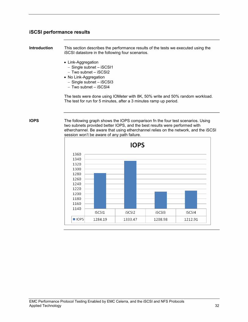
Introduction This section describes the performance results of the tests we executed using the
iSCSI datastore in the following four scenarios. • Link-Aggregation − Single subnet – iSCSI1 − Two subnet – iSCSI2
• No Link-Aggregation − Single subnet – iSCSI3 − Two subnet – iSCSI4
The tests were done using IOMeter with 8K, 50% write and 50% random workload. The test for run for 5 minutes, after a 3 minutes ramp up period.
IOPS The following graph shows the IOPS comparison fn the four test scenarios. Using
two subnets provided better IOPS, and the best results were performed with etherchannel. Be aware that using etherchannel relies on the network, and the iSCSI session won’t be aware of any path failure.

EMC Performance Protocol Testing Enabled by EMC Celerra, and the iSCSI and NFS Protocols Applied Technology 33
iSCSI datastore troubleshooting
Introduction This section provides some of the basic troubleshooting steps to use if you have
issues while accessing the iSCSI datastore on EMC Celerra.
EMC Celerra • Make sure the iSCSI service is started: From the Celerra console, run
server_iscsi server_2 –service -status • To restrict the ESX server to view and login to its own iSCSI targets, set the
parameter SendTargetsMode to 1 using the server_param command. By default, Celerra will pass all the iSCSI targets created.
• Verify the iSCSI LUNs are granted access to the iSCSI initiators using server_iscsi server_2 –mask -list
• If using you are Jumbo frame, it should be enabled throughout the data path. To check the MTU of the interface, use the server_ifconfig command or Celerra GUI.
• If VLAN tagging is used, you can check or set it using the server_ifconfig command
or using the Celerra GUI. • Check pinging of the ESX server's vmkernel port ip address from the Data Mover
port. This can be done using the server_ping cli command or using Celerra GUI.
Cisco switch • Check that the ports are up.
• Verify that the ports are configured properly (ensure correct VLAN setting, link aggregation, and so on).
• Verify whether it is able to ping the Data Mover and ESX ports. • Check the flow control (receive on) and Jumbo frame setting (if used). • Test etherchannel and ensure it picks the right port.

EMC Performance Protocol Testing Enabled by EMC Celerra, and the iSCSI and NFS Protocols Applied Technology 34
VMware ESX server
• Ensure that the VMkernel port is created on the correct vSwitch. • Check whether the vmkernel port is able to ping the Data Mover IP using the
vmkping command
• If link aggregation is used, the load balancing policy of the vSwitch should be set to
Route based on IP hash. If not, use Route based on the originating virtual port ID
• Use esxcfg-mpath or the vCenter client to verify the path selection policy. Make
sure it is set to Round Robin for EMC Celerra iSCSI. To view the round robin policy, use the following command: esxcli nmp device list | awk '/^naa/{print "esxcli nmp device setpolicy --device "$0" --psp VMW_PSP_RR" };'
• Check the Round Robin policy to use one I/O per path using: esxcli nmp device list If not, the following command can be used to display the command that can set the policy to use one I/O per path. esxcli nmp device list | aek ‘/^naa/{print “esxcli nmp roundrobin setconfig --device “$0” --type IOPS --IOPS 1”};’
• To check the iSCSI session information, first identify the SCSI controller number of iSCSI HBA using: cat /proc/vmware/vmkstor and identify the SCSI number for the VMKernal HBA for iSCSI controller. then, use:

EMC Performance Protocol Testing Enabled by EMC Celerra, and the iSCSI and NFS Protocols Applied Technology 35
cat /proc/scsi/iscsi_vmk/<scsi number> • If you are using Jumbo frames, it must be enabled on all ports of the iSCSI path.
To verify or set VMKernel port setting, use the esxcfg-vmknic command.
• To check the Disk I/O statistics, use the vscsistats command or use esxtop or
vCenter Client for further statistics. • Refer to VMware KB article 1007371 and 1004048 if you are using link aggregation
and it is not load balanced properly. • Check the vmkwarning logs for any evidence.

EMC Performance Protocol Testing Enabled by EMC Celerra, and the iSCSI and NFS Protocols Applied Technology 36
Performance analysis
Using one I/O per path
The default policy will send 1000 IOs per path before switching the I/O to another path.
If you are using one datastore, you will notice that the traffic is going through a single interface most of the time. We observed that changing the policy to use one I/O per path produced better throughput and utilized all of the paths.
Note: Before changing any default parameters in your VMware environment, be sure to verify that the resulting configuration is supported by VMware.

EMC Performance Protocol Testing Enabled by EMC Celerra, and the iSCSI and NFS Protocols Applied Technology 37
Using PowerPath/VE with an EMC Celerra iSCSI datastore
With PowerPath/VE 5.4.0 (b257), it didn’t automatically claim the EMC Celerra iSCSI datastore. PowerPath performed better than the default Round Robin policy on VMware, but produced similar results with modified round robin policy. With PowerPath/VE, we notice that the Least-I/O load-balancing policy (PP LI) produced better I/O than the default Adaptive load-balancing policy (PP AD) for our test workload.

EMC Performance Protocol Testing Enabled by EMC Celerra, and the iSCSI and NFS Protocols Applied Technology 38
PowerPath/VE load balancing policies
PowerPath/VE offers the following load-balancing policies: • Adaptive (default) • Round Robin • Streaming I/O • Least Block • Least I/O
For our test workload with two storage subnets on a link aggregation network on a
distributed switch, this is how each one performed.

EMC Performance Protocol Testing Enabled by EMC Celerra, and the iSCSI and NFS Protocols Applied Technology 39
Distributed switching
Distributed switching makes it easier to deploy vSphere, compared to the standard vSwitch. Distributed switching also helps in maintaining the network statistics during vMotion. What we observed is it produced similar results during our test.

EMC Performance Protocol Testing Enabled by EMC Celerra, and the iSCSI and NFS Protocols Applied Technology 40
Conclusion
Summary VMware vSphere and EMC Celerra provide flexibility when choosing a storage
protocol to meet a datastore's needs.
Findings The following results were determined using the stated test plan and methodology:
• A single storage subnet in link aggregation provided better performance for an
NFS datastore. • There is no need to assign a NIC to the iSCSI initiator when using link aggregation,
and it is needed when not using link aggregation.
Benefits Use the right topology and path selection policy to better achieve the performance
and fault tolerance for the VMware vSphere storage network.
Next steps EMC can help accelerate assessment, design, implementation, and management
while lowering the implementation risks and cost of creating a virtualized data center. To learn more about this and other solutions contact an EMC representative or visit www.emc.com.