Embed Size (px)
Citation preview
Solution Guide
SAP BUSINESS CONTINUITY ENABLED WITH EMC VMAX ALL FLASH Continuous Protection and Availability with SRDF/Metro
Stretched Metro cluster VMware vSphere 6.0 Oracle RAC 12c
EMC Solutions
Abstract
This solution guide describes an EMC solution for SAP that provides high availability and application live migration through the deployment of EMC SRDF/Metro, VMware vSphere HA, and Oracle RAC with active-active data centers.
April 2017
2 SAP Business Continuity Enabled with EMC VMAX All Flash Solution Guide
Copyright © 2017 EMC Corporation. All rights reserved. Published in the USA.
Published April 2017
EMC believes the information in this publication is accurate as of its publication date. The information is subject to change without notice.
The information in this publication is provided as is. EMC Corporation makes no representations or warranties of any kind with respect to the information in this publication, and specifically disclaims implied warranties of merchantability or fitness for a particular purpose. Use, copying, and distribution of any EMC software described in this publication requires an applicable software license.
EMC2, EMC, and the EMC logo are registered trademarks or trademarks of EMC Corporation in the United States and other countries. All other trademarks used herein are the property of their respective owners.
For the most up-to-date listing of EMC product names, see EMC Corporation Trademarks on EMC.com.
SAP Business Continuity Enabled with EMC VMAX All Flash Solution Guide
Part Number H14559.2
Contents
3 SAP Business Continuity Enabled with EMC VMAX All Flash Solution Guide
Contents
Chapter 1 Executive Summary 5Business case ............................................................................................................ 6
Solution overview ....................................................................................................... 6
Key benefits ............................................................................................................... 7
Document purpose ..................................................................................................... 7
Audience .................................................................................................................... 7
Terminology ................................................................................................................ 8
We value your feedback! ............................................................................................. 8
Chapter 2 Technology Overview 9Solution architecture ................................................................................................ 10
Storage high availability ...................................................................................... 12
Network high availability ..................................................................................... 12
Key components ....................................................................................................... 12
EMC VMAX All Flash ............................................................................................. 12
SRDF/Metro ......................................................................................................... 13
Unisphere for VMAX ............................................................................................. 15
SAP Business Suite .............................................................................................. 15
SAP Power Benchmark ......................................................................................... 16
VMware vSphere .................................................................................................. 17
vSphere FT ........................................................................................................... 17
Extended Oracle RAC ........................................................................................... 17
Hardware resources .................................................................................................. 18
Software resources ................................................................................................... 18
Chapter 3 Design Considerations and Configurations 20Overview .................................................................................................................. 21
Auto-start of SAP instances ...................................................................................... 21
vSphere HA and DRS ................................................................................................ 23
Admission control ................................................................................................ 23
Virtual machine restart priority ............................................................................. 24
DRS rules ............................................................................................................. 24
DRS rules for RAC ................................................................................................. 24
SRDF/Metro configuration ........................................................................................ 25
SAP on Oracle RAC configuration .............................................................................. 30
Contents
4 SAP Business Continuity Enabled with EMC VMAX All Flash Solution Guide
Protection layer .................................................................................................... 30
Virtual machine configuration .............................................................................. 30
Storage configuration .......................................................................................... 31
Installation .......................................................................................................... 32
Chapter 4 Test and Validation 33Overview .................................................................................................................. 34
Planned ESXi host maintenance ............................................................................... 34
Introduction ......................................................................................................... 34
Test procedure ..................................................................................................... 35
Results ................................................................................................................ 36
Analysis ............................................................................................................... 37
Data center failure with a single-instance Oracle database ....................................... 37
Introduction ......................................................................................................... 37
Test procedure ..................................................................................................... 38
Results ................................................................................................................ 39
Analysis ............................................................................................................... 42
Data center failure in an Extended Oracle RAC environment ...................................... 42
Introduction ......................................................................................................... 42
Failure of the RAC node ........................................................................................ 43
Failure of the RAC interconnect network ............................................................... 43
Failure of an ASCS virtual machine ....................................................................... 44
Failure of a data center ........................................................................................ 44
Analysis ............................................................................................................... 45
Chapter 5 Conclusion 46Summary .................................................................................................................. 47
Chapter 6 References 48EMC documentation ................................................................................................. 49
SAP documentation .................................................................................................. 49
VMware documentation ............................................................................................ 49
Oracle documentation .............................................................................................. 49
Chapter 1: Executive Summary
5 SAP Business Continuity Enabled with EMC VMAX All Flash Solution Guide
Chapter 1 Executive Summary
This chapter presents the following topics:
Business case .......................................................................................................... 6
Solution overview .................................................................................................... 6
Key benefits ............................................................................................................ 7
Document purpose ................................................................................................... 7
Audience ................................................................................................................. 7
Terminology ............................................................................................................ 8
We value your feedback! .......................................................................................... 8
Chapter 1: Executive Summary
6 SAP Business Continuity Enabled with EMC VMAX All Flash Solution Guide
Business case
IT leaders are increasingly transferring mission-critical SAP applications to virtual infrastructures to gain cost savings, simplified management, and data center efficiencies.
This transition brings new opportunities to address an increasing demand for high availability of mission-critical applications such as SAP.
High availability and application live migration are essential for SAP applications. They provide non-disruptive and live workload migrations within or across data centers and implement fully automated restarts when outages happen.
In traditional infrastructure designs, companies typically have a primary data center running production systems, and a secondary site for failover in the event of disruption in the primary site. Typically this is an active-passive configuration leading to several challenges for IT. First, the passive secondary site is underutilized, which leads to higher total cost of ownership (TCO). Second, an active-passive mode results in longer downtime and potential data loss, which increases risk to the business.
The solution described in this guide addresses these challenges for SAP applications, offering the following dual strategies to enhance application availability:
High availability, providing near-zero recovery time objective (RTO) andrecovery point objective (RPO), which helps to manage risks in an ITenvironment and plans for recovery when a technical failure occurs
Application live migration for higher utilization, which moves runningworkloads without disruption between servers to avoid any downtimeresulting from planned maintenance or an unforeseeable outage
Solution overview
This continuous availability solution uses EMC® Symmetrix Remote Data Facility (SRDF®)/Metro™ and VMware vSphere High Availability (HA) to enable continuous availability and application live migration within an SAP virtual infrastructure deployment. It provides the following functions:
Automated non-disruptive virtual machine migration within a stretched metroclustered data center running SAP mission-critical applications
Simple automated infrastructure vSphere HA protection for the entire SAPenvironment across a metro distance
Protection from all single points of failure
Continuous availability
Additional functions include:
Automatic restart of virtual machines in the event of server failures
Automatic load balancing between data centers
Zero downtime on maintenance
Chapter 1: Executive Summary
7 SAP Business Continuity Enabled with EMC VMAX All Flash Solution Guide
Key benefits
SRDF/Metro helps with almost any outage scenario through active-active continuous availability that fully utilizes all assets and simplifies IT infrastructure.
SRDF/Metro enables organizations to:
Increase trust in their IT infrastructure by replacing manual recovery practiceswith fast, automated processes that reduce the chance of human error
Improve efficiency by unifying continuous availability and disaster recoveryprocesses into a streamlined capability
Optimize SAP availability and performance by dynamically load-balancingworkloads across arrays within and across data centers
Run migrations, maintenance, and technology refreshes during normalbusiness hours without disrupting application and user access
Dynamically move applications or entire data centers without interrupting dataprocessing
Document purpose
This solution guide describes a continuous availability solution for SAP virtual infrastructure deployments. The document:
Introduces the technical components that are needed to implement andoperate the solution
Describes the testing and validation of the solution’s functionality
Evaluates the technical and business value of the solution in the context of anSAP virtualized landscape
Audience
This solution guide is intended for executives, managers, SAP architects, IT administrators, and technical administrators of IT environments who want to implement continuous availability for virtual infrastructures managing SAP landscapes. Readers should be familiar with VMware vSphere, storage technologies, and general IT functions and requirements, and how they fit into the SAP architecture.
Chapter 1: Executive Summary
8 SAP Business Continuity Enabled with EMC VMAX All Flash Solution Guide
Terminology
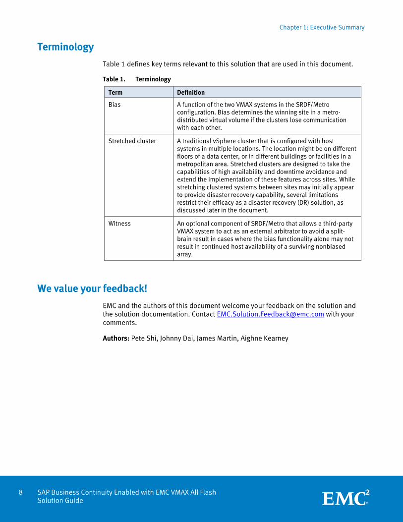
Table 1 defines key terms relevant to this solution that are used in this document.
Table 1. Terminology
Term Definition
Bias A function of the two VMAX systems in the SRDF/Metro configuration. Bias determines the winning site in a metro-distributed virtual volume if the clusters lose communication with each other.
Stretched cluster A traditional vSphere cluster that is configured with host systems in multiple locations. The location might be on different floors of a data center, or in different buildings or facilities in a metropolitan area. Stretched clusters are designed to take the capabilities of high availability and downtime avoidance and extend the implementation of these features across sites. While stretching clustered systems between sites may initially appear to provide disaster recovery capability, several limitations restrict their efficacy as a disaster recovery (DR) solution, as discussed later in the document.
Witness An optional component of SRDF/Metro that allows a third-party VMAX system to act as an external arbitrator to avoid a split-brain result in cases where the bias functionality alone may not result in continued host availability of a surviving nonbiased array.
We value your feedback!
EMC and the authors of this document welcome your feedback on the solution and the solution documentation. Contact [email protected] with your comments.
Authors: Pete Shi, Johnny Dai, James Martin, Aighne Kearney
Chapter 2: Technology Overview
9 SAP Business Continuity Enabled with EMC VMAX All Flash Solution Guide
Chapter 2 Technology Overview
This chapter presents the following topics:
Solution architecture ............................................................................................. 10
Key components .................................................................................................... 12
Hardware resources ............................................................................................... 18
Software resources ................................................................................................ 18
Chapter 2: Technology Overview
10 SAP Business Continuity Enabled with EMC VMAX All Flash Solution Guide
Solution architecture
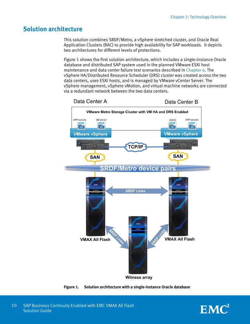
This solution combines SRDF/Metro, a vSphere stretched cluster, and Oracle Real Application Clusters (RAC) to provide high availability for SAP workloads. It depicts two architectures for different levels of protections.
Figure 1 shows the first solution architecture, which includes a single-instance Oracle database and distributed SAP system used in the planned VMware ESXi host maintenance and data center failure test scenarios described in Chapter 4. The vSphere HA/Distributed Resource Scheduler (DRS) cluster was created across the two data centers, uses ESXi hosts, and is managed by VMware vCenter Server. The vSphere management, vSphere vMotion, and virtual machine networks are connected via a redundant network between the two data centers.
Figure 1. Solution architecture with a single-instance Oracle database
Chapter 2: Technology Overview
11 SAP Business Continuity Enabled with EMC VMAX All Flash Solution Guide
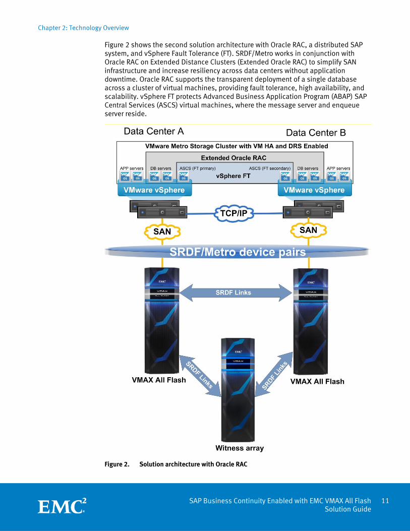
Figure 2 shows the second solution architecture with Oracle RAC, a distributed SAP system, and vSphere Fault Tolerance (FT). SRDF/Metro works in conjunction with Oracle RAC on Extended Distance Clusters (Extended Oracle RAC) to simplify SAN infrastructure and increase resiliency across data centers without application downtime. Oracle RAC supports the transparent deployment of a single database across a cluster of virtual machines, providing fault tolerance, high availability, and scalability. vSphere FT protects Advanced Business Application Program (ABAP) SAP Central Services (ASCS) virtual machines, where the message server and enqueue server reside.
Figure 2. Solution architecture with Oracle RAC
Chapter 2: Technology Overview
12 SAP Business Continuity Enabled with EMC VMAX All Flash Solution Guide
This solution uses SRDF/Metro across the two data centers to provide active-active storage access to all the ESXi hosts, using the SRDF/Metro device pairs. Devices in both data centers appear as a single virtual device across the two SRDF paired arrays for host presentation. The hosts can read and write to both paired arrays with SRDF/Metro.
This solution also uses an SRDF/Metro witness to determine the bias device when the SRDF/Metro link is suspended or failure occurs. The witness is a third EMC VMAX® array with SRDF connectivity.
In each data center, a redundant 10 gigabit Ethernet (GbE) fabric provides the core IP network for data center traffic and uplinks for user access. The same IP subnets are available at both data centers. The Layer 2 routers extend the Layer 2 connection across both data centers.
Key components
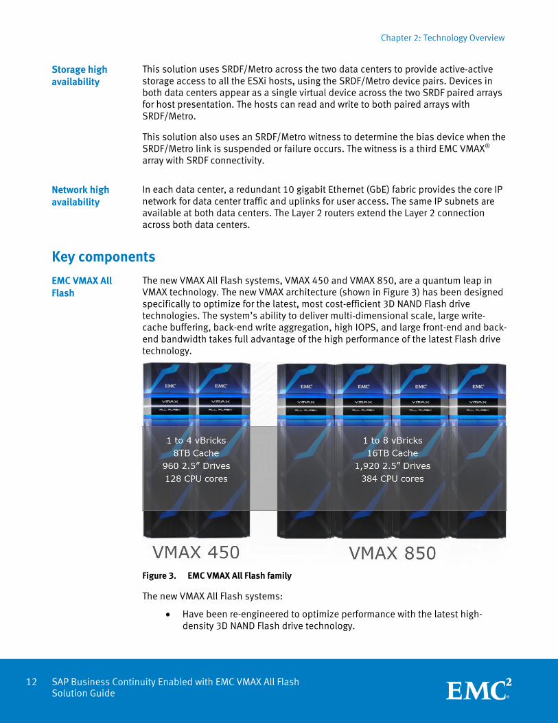
The new VMAX All Flash systems, VMAX 450 and VMAX 850, are a quantum leap in VMAX technology. The new VMAX architecture (shown in Figure 3) has been designed specifically to optimize for the latest, most cost-efficient 3D NAND Flash drive technologies. The system’s ability to deliver multi-dimensional scale, large write-cache buffering, back-end write aggregation, high IOPS, and large front-end and back-end bandwidth takes full advantage of the high performance of the latest Flash drive technology.
Figure 3. EMC VMAX All Flash family
The new VMAX All Flash systems:
Have been re-engineered to optimize performance with the latest high-density 3D NAND Flash drive technology.
Storage high availability
Network high availability
EMC VMAX All Flash
Chapter 2: Technology Overview
13 SAP Business Continuity Enabled with EMC VMAX All Flash Solution Guide
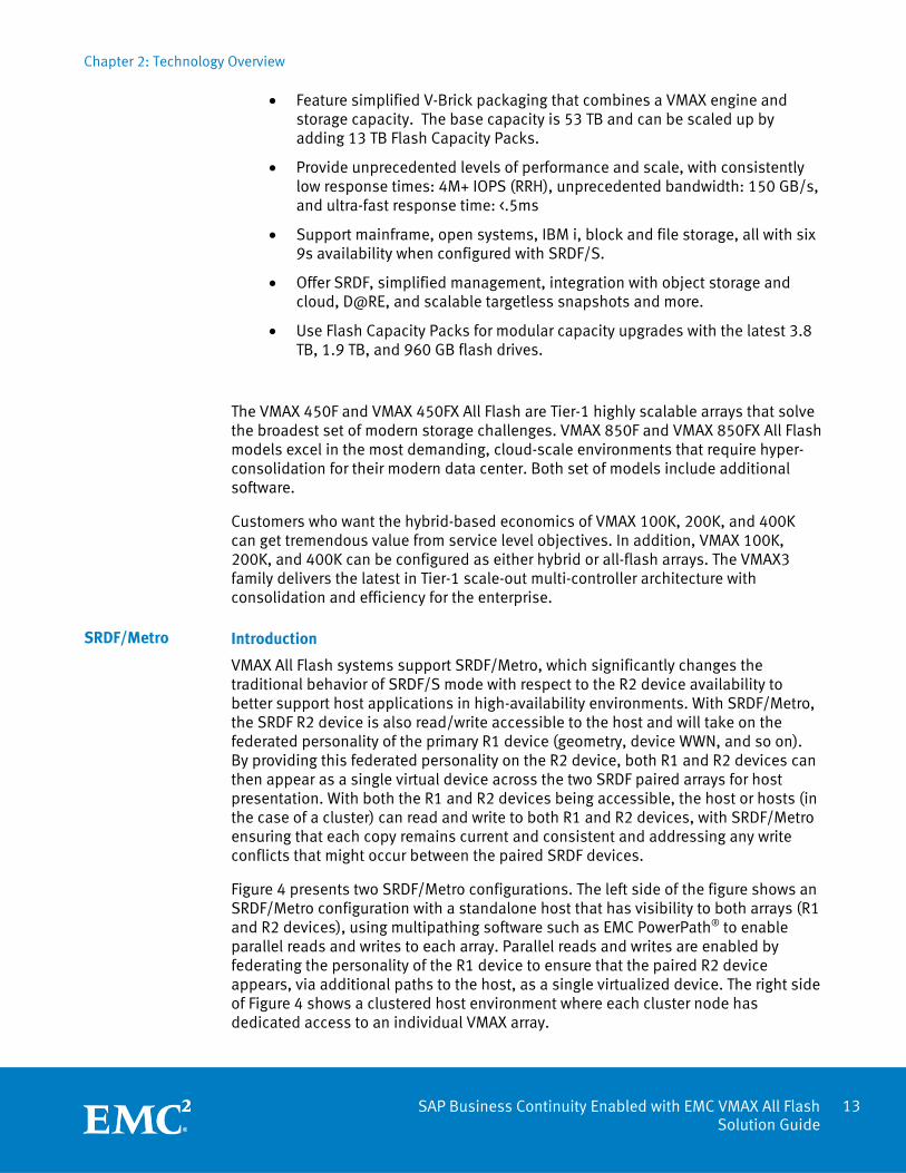
Feature simplified V-Brick packaging that combines a VMAX engine andstorage capacity. The base capacity is 53 TB and can be scaled up byadding 13 TB Flash Capacity Packs.
Provide unprecedented levels of performance and scale, with consistentlylow response times: 4M+ IOPS (RRH), unprecedented bandwidth: 150 GB/s,and ultra-fast response time: <.5ms
Support mainframe, open systems, IBM i, block and file storage, all with six9s availability when configured with SRDF/S.
Offer SRDF, simplified management, integration with object storage andcloud, D@RE, and scalable targetless snapshots and more.
Use Flash Capacity Packs for modular capacity upgrades with the latest 3.8TB, 1.9 TB, and 960 GB flash drives.
The VMAX 450F and VMAX 450FX All Flash are Tier-1 highly scalable arrays that solve the broadest set of modern storage challenges. VMAX 850F and VMAX 850FX All Flash models excel in the most demanding, cloud-scale environments that require hyper-consolidation for their modern data center. Both set of models include additional software.
Customers who want the hybrid-based economics of VMAX 100K, 200K, and 400K can get tremendous value from service level objectives. In addition, VMAX 100K, 200K, and 400K can be configured as either hybrid or all-flash arrays. The VMAX3 family delivers the latest in Tier-1 scale-out multi-controller architecture with consolidation and efficiency for the enterprise.
Introduction
VMAX All Flash systems support SRDF/Metro, which significantly changes the traditional behavior of SRDF/S mode with respect to the R2 device availability to better support host applications in high-availability environments. With SRDF/Metro, the SRDF R2 device is also read/write accessible to the host and will take on the federated personality of the primary R1 device (geometry, device WWN, and so on). By providing this federated personality on the R2 device, both R1 and R2 devices can then appear as a single virtual device across the two SRDF paired arrays for host presentation. With both the R1 and R2 devices being accessible, the host or hosts (in the case of a cluster) can read and write to both R1 and R2 devices, with SRDF/Metro ensuring that each copy remains current and consistent and addressing any write conflicts that might occur between the paired SRDF devices.
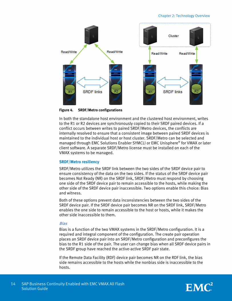
Figure 4 presents two SRDF/Metro configurations. The left side of the figure shows an SRDF/Metro configuration with a standalone host that has visibility to both arrays (R1 and R2 devices), using multipathing software such as EMC PowerPath® to enable parallel reads and writes to each array. Parallel reads and writes are enabled by federating the personality of the R1 device to ensure that the paired R2 device appears, via additional paths to the host, as a single virtualized device. The right side of Figure 4 shows a clustered host environment where each cluster node has dedicated access to an individual VMAX array.
SRDF/Metro
Chapter 2: Technology Overview
14 SAP Business Continuity Enabled with EMC VMAX All Flash Solution Guide
Figure 4. SRDF/Metro configurations
In both the standalone host environment and the clustered host environment, writes to the R1 or R2 devices are synchronously copied to their SRDF paired devices. If a conflict occurs between writes to paired SRDF/Metro devices, the conflicts are internally resolved to ensure that a consistent image between paired SRDF devices is maintained to the individual host or host cluster. SRDF/Metro can be selected and managed through EMC Solutions Enabler SYMCLI or EMC Unisphere® for VMAX or later client software. A separate SRDF/Metro license must be installed on each of the VMAX systems to be managed.
SRDF/Metro resiliency
SRDF/Metro utilizes the SRDF link between the two sides of the SRDF device pair to ensure consistency of the data on the two sides. If the status of the SRDF device pair becomes Not Ready (NR) on the SRDF link, SRDF/Metro must respond by choosing one side of the SRDF device pair to remain accessible to the hosts, while making the other side of the SRDF device pair inaccessible. Two options enable this choice: Bias and witness.
Both of these options prevent data inconsistencies between the two sides of the SRDF device pair. If the SRDF device pair becomes NR on the SRDF link, SRDF/Metro enables the one side to remain accessible to the host or hosts, while it makes the other side inaccessible to them.
Bias Bias is a function of the two VMAX systems in the SRDF/Metro configuration. It is a required and integral component of the configuration. The create pair operation places an SRDF device pair into an SRDF/Metro configuration and preconfigures the bias to the R1 side of the pair. The user can change bias when all SRDF device pairs in the SRDF group have reached the active-active SRDF pair state.
If the Remote Data Facility (RDF) device pair becomes NR on the RDF link, the bias side remains accessible to the hosts while the nonbias side is inaccessible to the hosts.
Chapter 2: Technology Overview
15 SAP Business Continuity Enabled with EMC VMAX All Flash Solution Guide
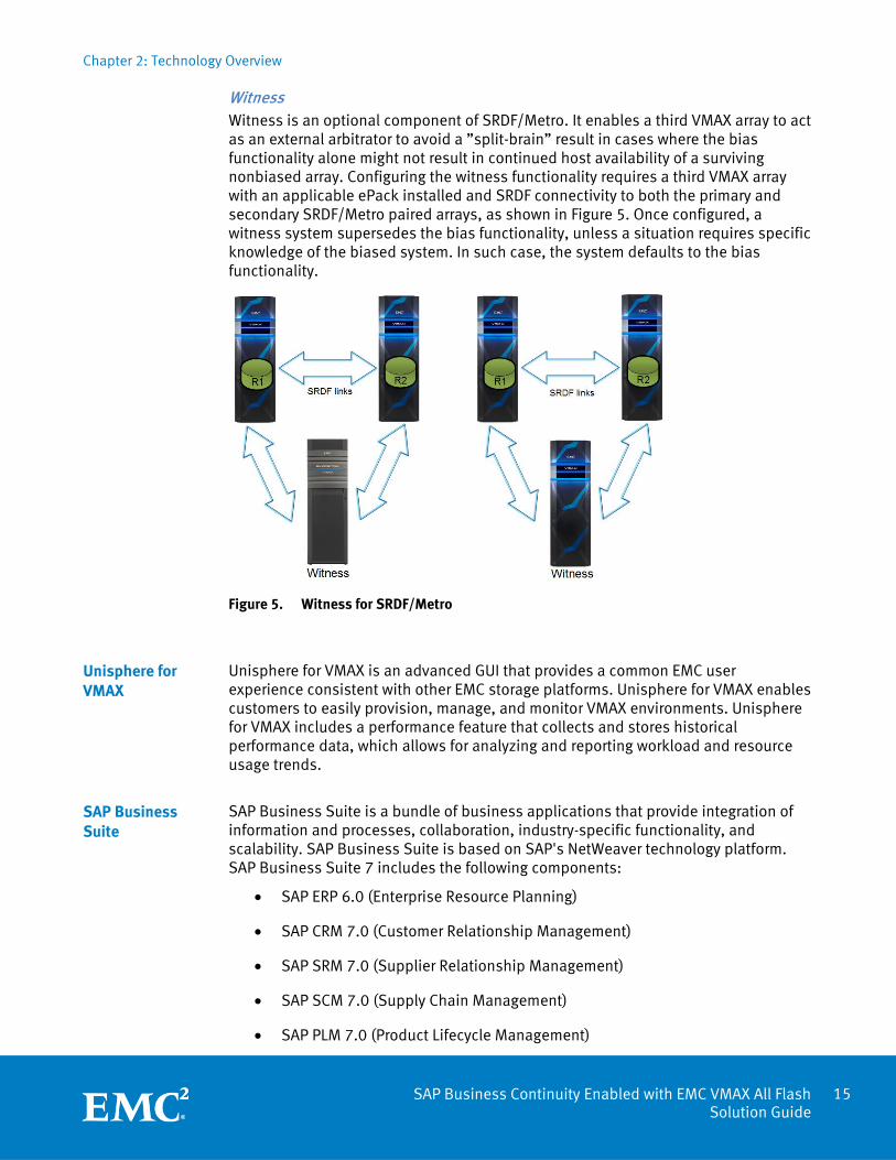
Witness Witness is an optional component of SRDF/Metro. It enables a third VMAX array to act as an external arbitrator to avoid a ”split-brain” result in cases where the bias functionality alone might not result in continued host availability of a surviving nonbiased array. Configuring the witness functionality requires a third VMAX array with an applicable ePack installed and SRDF connectivity to both the primary and secondary SRDF/Metro paired arrays, as shown in Figure 5. Once configured, a witness system supersedes the bias functionality, unless a situation requires specific knowledge of the biased system. In such case, the system defaults to the bias functionality.
Figure 5. Witness for SRDF/Metro
Unisphere for VMAX is an advanced GUI that provides a common EMC user experience consistent with other EMC storage platforms. Unisphere for VMAX enables customers to easily provision, manage, and monitor VMAX environments. Unisphere for VMAX includes a performance feature that collects and stores historical performance data, which allows for analyzing and reporting workload and resource usage trends.
SAP Business Suite is a bundle of business applications that provide integration of information and processes, collaboration, industry-specific functionality, and scalability. SAP Business Suite is based on SAP's NetWeaver technology platform. SAP Business Suite 7 includes the following components:
SAP ERP 6.0 (Enterprise Resource Planning)
SAP CRM 7.0 (Customer Relationship Management)
SAP SRM 7.0 (Supplier Relationship Management)
SAP SCM 7.0 (Supply Chain Management)
SAP PLM 7.0 (Product Lifecycle Management)
Unisphere for VMAX
SAP Business Suite

Chapter 2: Technology Overview
16 SAP Business Continuity Enabled with EMC VMAX All Flash Solution Guide
We used SAP ERP 6.0 in the test environment for this solution.
For this solution, we used SAP Power Benchmark, derived from the SAP Sales and Distribution (SD) Benchmark, to simulate user login activity on the installed SAP ERP 6.0 EHP7 system, which was built for the test scenarios. The SAP-specific workload used in the Test and Validation scenarios demonstrates SAP application live migration across data centers during the hardware maintenance.
The SAP Power Benchmark toolkit performed predefined standard SD transactions against the SAP system. The toolkit includes a sell-from-stock business scenario that consists of the following transactions:
(VA01) Create a sales order with five line items
(VL01N) Create a delivery for the order
(VA03) Display the customer order
(VL02N) Change the delivery and post a goods issue
(VA05) List 40 orders for sold-to party
(VF01) Create an invoice for the order
SAP Power Benchmark
Chapter 2: Technology Overview
17 SAP Business Continuity Enabled with EMC VMAX All Flash Solution Guide
The vSphere virtualization layer decouples the application from the underlying physical resources. This decoupling enables greater flexibility in the application layer by eliminating hardware downtime for maintenance and enabling changes to be made to the physical system without affecting the hosted applications. In a server virtualization use case, this layer enables multiple independent virtual machines to share the same physical hardware.
vSphere is a complete and robust virtualization platform, virtualizing business-critical applications with dynamic resource pools for flexibility and reliability. It transforms the physical resources of a computer by virtualizing the CPU, RAM, hard disk, and network controller. This transformation creates fully functional virtual machines that run isolated and encapsulated operating systems and applications.
VMware vSphere Fault Tolerance (FT) provides continuous availability for applications in the event of physical server failures by creating a live shadow instance of a virtual machine that is always up to date with the primary virtual machine. If a hardware outage occurs, vSphere FT automatically triggers failover, ensuring zero downtime and preventing data loss. vSphere FT is easy to set up and configure and does not require OS-specific or application-specific agents or configuration. It is tightly integrated with vSphere and is managed using vSphere Web Client. FT is included with the VMware vSphere Essentials Plus Kit and higher editions of vSphere.
Through the use of a completely new fast-checkpointing technology, vSphere FT 6.0 now supports protection of virtual machines with up to four vCPUs and 64 GB of memory. This means that the majority of mission-critical customer workloads can be protected, regardless of the application or OS. Applications that are highly sensitive to network latency have a higher performance cost under FT protection, however, and in this case FT is only used to protect the ASCS server.
Extended Oracle RAC is an architecture that enables all nodes in the cluster to reside in physically separate locations. It provides high availability and business continuity during a data center or network failure as follows:
Storage and data remain available and active on the surviving data center.
Oracle services load balance and fail over to the Oracle RAC nodes on the surviving data center.
Oracle Transparent Application Failover (TAF) enables sessions to automatically fail over to Oracle RAC nodes on the surviving data center.
Oracle RAC nodes on the surviving data center continue to process transactions.
Oracle advises that the Extended Oracle RAC architecture works best when the two data centers are relatively close (no more than 100 km apart). EMC recommends a maximum latency of 1 ms.
VMware vSphere
vSphere FT
Extended Oracle RAC
Chapter 2: Technology Overview
18 SAP Business Continuity Enabled with EMC VMAX All Flash Solution Guide
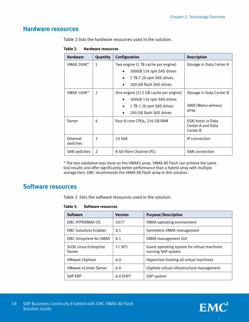
Hardware resources
Table 2 lists the hardware resources used in the solution.
Table 2. Hardware resources
Hardware Quantity Configuration Description
VMAX 200K* 1 Two engine (1 TB cache per engine)
300GB 15k rpm SAS drives
1 TB 7.2k rpm SAS drives
200 GB flash SAS drives
Storage in Data Center A
VMAX 100K* 2 One engine (512 GB cache per engine)
300GB 15k rpm SAS drives
1 TB 7.2k rpm SAS drives
200 GB flash SAS drives
Storage in Data Center B
SRDF/Metro witness array
Server 4 Four 8-core CPUs, 256 GB RAM ESXi hosts in Data Center A and Data Center B
Ethernet switches
2 10 GbE IP connection
SAN switches 2 8 Gb Fibre Channel (FC) SAN connection
* The test validation was done on the VMAX3 array. VMAX All Flash can achieve the same test results and offer significantly better performance than a hybrid array with multiple storage tiers. EMC recommends the VMAX All Flash array in this solution.
Software resources
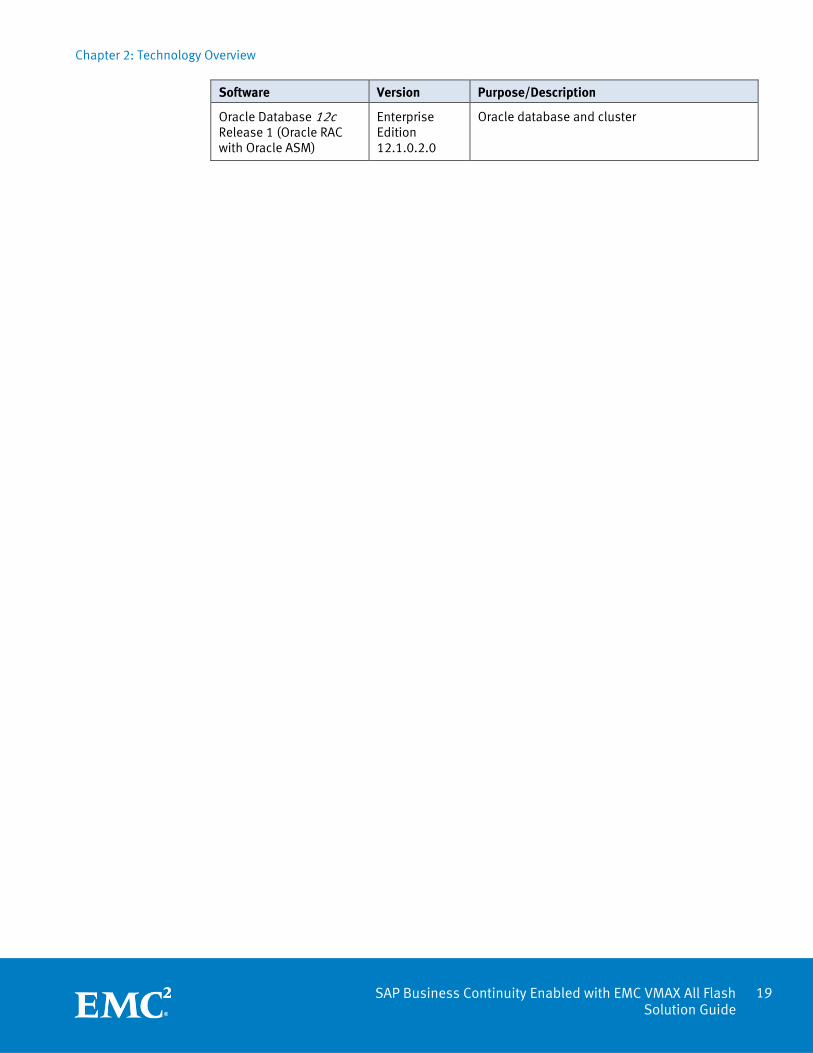
Table 3 lists the software resources used in the solution.
Table 3. Software resources
Software Version Purpose/Description
EMC HYPERMAX OS 5977 VMAX operating environment
EMC Solutions Enabler 8.1 Symmetrix VMAX management
EMC Unisphere for VMAX 8.1 VMAX management GUI
SUSE Linux Enterprise Server
11 SP3 Guest operating system for virtual machines running SAP system
VMware vSphere 6.0 Hypervisor hosting all virtual machines
VMware vCenter Server 6.0 vSphere virtual infrastructure management
SAP ERP 6.0 EHP7 SAP system
Chapter 2: Technology Overview
19 SAP Business Continuity Enabled with EMC VMAX All Flash Solution Guide
Software Version Purpose/Description
Oracle Database 12c Release 1 (Oracle RAC with Oracle ASM)
Enterprise Edition 12.1.0.2.0
Oracle database and cluster
Chapter 3: Design Considerations and Configurations
20 SAP Business Continuity Enabled with EMC VMAX All Flash Solution Guide
Chapter 3 Design Considerations and Configurations
This chapter presents the following topics:
Overview ............................................................................................................... 21
Auto-start of SAP instances ................................................................................... 21
vSphere HA and DRS .............................................................................................. 23
SRDF/Metro configuration ..................................................................................... 25
Chapter 3: Design Considerations and Configurations
21 SAP Business Continuity Enabled with EMC VMAX All Flash Solution Guide
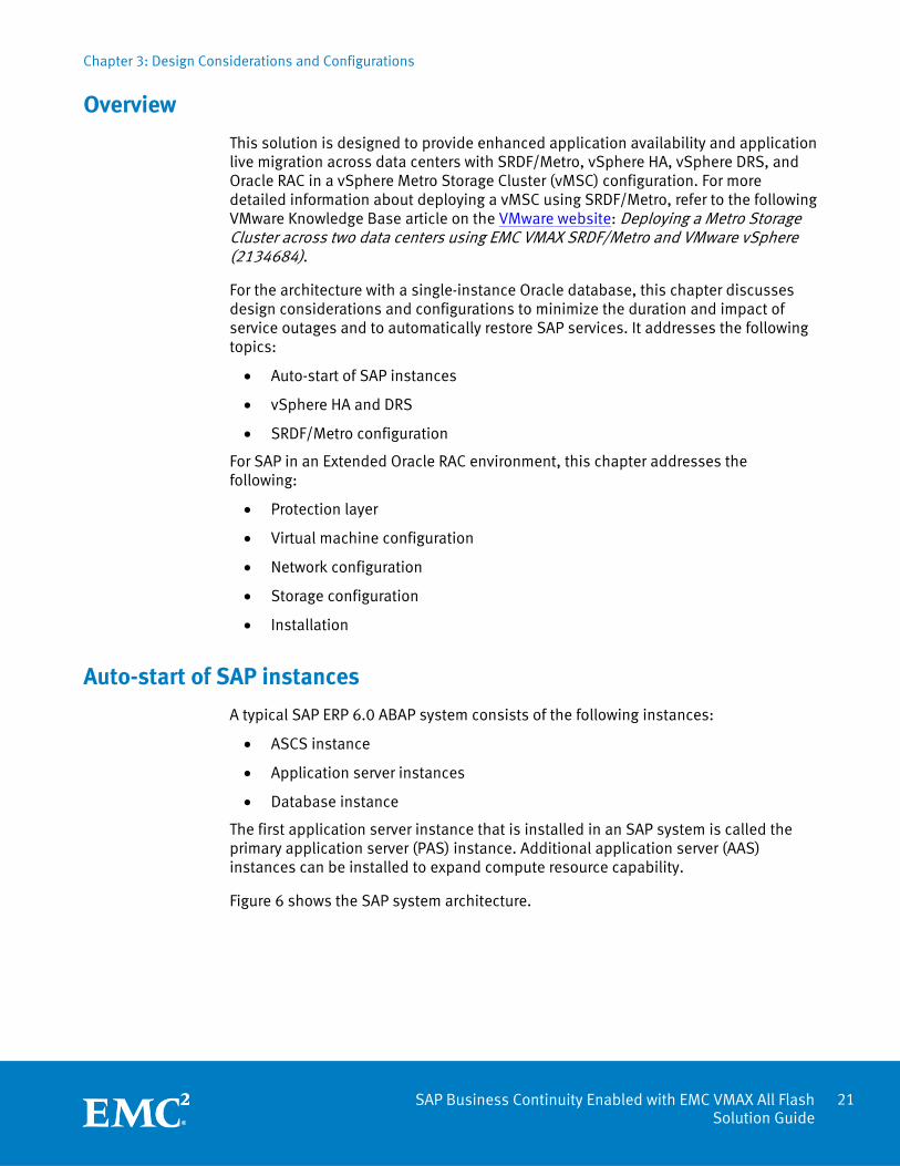
Overview
This solution is designed to provide enhanced application availability and application live migration across data centers with SRDF/Metro, vSphere HA, vSphere DRS, and Oracle RAC in a vSphere Metro Storage Cluster (vMSC) configuration. For more detailed information about deploying a vMSC using SRDF/Metro, refer to the following VMware Knowledge Base article on the VMware website: Deploying a Metro Storage Cluster across two data centers using EMC VMAX SRDF/Metro and VMware vSphere (2134684).
For the architecture with a single-instance Oracle database, this chapter discusses design considerations and configurations to minimize the duration and impact of service outages and to automatically restore SAP services. It addresses the following topics:
Auto-start of SAP instances
vSphere HA and DRS
SRDF/Metro configuration
For SAP in an Extended Oracle RAC environment, this chapter addresses the following:
Protection layer
Virtual machine configuration
Network configuration
Storage configuration
Installation
Auto-start of SAP instances
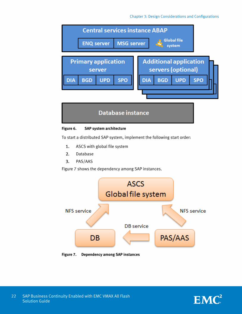
A typical SAP ERP 6.0 ABAP system consists of the following instances:
ASCS instance
Application server instances
Database instance
The first application server instance that is installed in an SAP system is called the primary application server (PAS) instance. Additional application server (AAS) instances can be installed to expand compute resource capability.
Figure 6 shows the SAP system architecture.
Chapter 3: Design Considerations and Configurations
22 SAP Business Continuity Enabled with EMC VMAX All Flash Solution Guide
Figure 6. SAP system architecture
To start a distributed SAP system, implement the following start order:
1. ASCS with global file system
2. Database
3. PAS/AAS
Figure 7 shows the dependency among SAP instances.
Figure 7. Dependency among SAP instances
Chapter 3: Design Considerations and Configurations
23 SAP Business Continuity Enabled with EMC VMAX All Flash Solution Guide
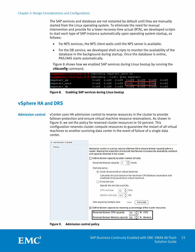
The SAP services and database are not restarted by default until they are manually started from the Linux operating system. To eliminate the need for manual intervention and provide for a lower recovery time actual (RTA), we developed scripts to start each type of SAP instance automatically upon operating system startup, as follows:
For NFS services, the NFS client waits until the NFS server is available.
For the DB service, we developed shell scripts to monitor the availability of the database in the background during startup. Once the database is online, PAS/AAS starts automatically.
Figure 8 shows how we enabled SAP services during Linux bootup by running the chkconfig command.
Figure 8. Enabling SAP services during Linux bootup
vSphere HA and DRS
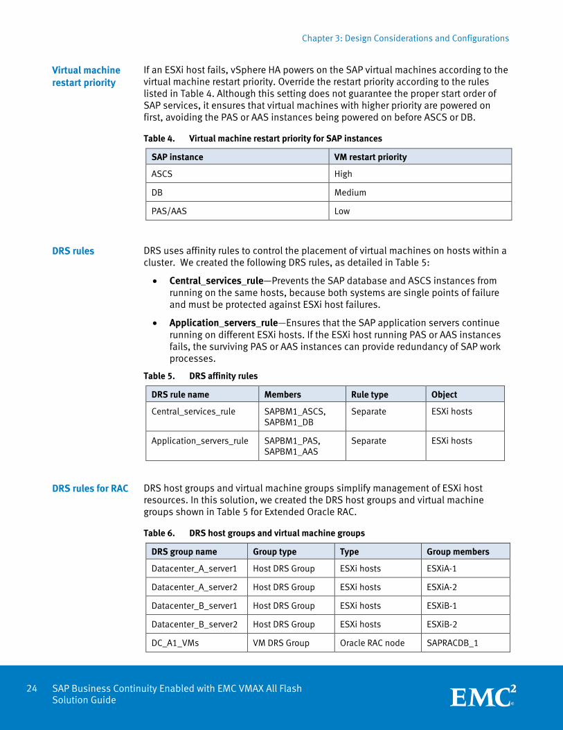
vCenter uses HA admission control to reserve resources in the cluster to provide failover protection and ensure virtual machine resource reservations. As shown in Figure 9, we set the policy for reserved cluster resources to 50 percent. This configuration reserves cluster compute resources to guarantee the restart of all virtual machines to another surviving data center in the event of failure of a single data center.
Figure 9. Admission control policy
Admission control
Chapter 3: Design Considerations and Configurations
24 SAP Business Continuity Enabled with EMC VMAX All Flash Solution Guide
If an ESXi host fails, vSphere HA powers on the SAP virtual machines according to the virtual machine restart priority. Override the restart priority according to the rules listed in Table 4. Although this setting does not guarantee the proper start order of SAP services, it ensures that virtual machines with higher priority are powered on first, avoiding the PAS or AAS instances being powered on before ASCS or DB.
Table 4. Virtual machine restart priority for SAP instances
SAP instance VM restart priority
ASCS High
DB Medium
PAS/AAS Low
DRS uses affinity rules to control the placement of virtual machines on hosts within a cluster. We created the following DRS rules, as detailed in Table 5:
Central_services_rule—Prevents the SAP database and ASCS instances from running on the same hosts, because both systems are single points of failure and must be protected against ESXi host failures.
Application_servers_rule—Ensures that the SAP application servers continue running on different ESXi hosts. If the ESXi host running PAS or AAS instances fails, the surviving PAS or AAS instances can provide redundancy of SAP work processes.
Table 5. DRS affinity rules
DRS rule name Members Rule type Object
Central_services_rule SAPBM1_ASCS, SAPBM1_DB
Separate ESXi hosts
Application_servers_rule SAPBM1_PAS, SAPBM1_AAS
Separate ESXi hosts
DRS host groups and virtual machine groups simplify management of ESXi host resources. In this solution, we created the DRS host groups and virtual machine groups shown in Table 5 for Extended Oracle RAC.
Table 6. DRS host groups and virtual machine groups
DRS group name Group type Type Group members
Datacenter_A_server1 Host DRS Group ESXi hosts ESXiA-1
Datacenter_A_server2 Host DRS Group ESXi hosts ESXiA-2
Datacenter_B_server1 Host DRS Group ESXi hosts ESXiB-1
Datacenter_B_server2 Host DRS Group ESXi hosts ESXiB-2
DC_A1_VMs VM DRS Group Oracle RAC node SAPRACDB_1
Virtual machine restart priority
DRS rules
DRS rules for RAC
Chapter 3: Design Considerations and Configurations
25 SAP Business Continuity Enabled with EMC VMAX All Flash Solution Guide
DRS group name Group type Type Group members
DC_A2_VMs VM DRS Group Oracle RAC node SAPRACDB_2
DC_B1_VMs VM DRS Group Oracle RAC node SAPRACDB_3
DC_A2_VMs VM DRS Group Oracle RAC node SAPRACDB_4
After we created DRS groups, we created DRS rules to control the placement of virtual machines on hosts within a cluster. Table 7 shows the DRS rules we created for the Oracle RAC nodes. The condition for both rules is should run, not must run. The should run condition gives flexibility for the virtual machines to start up on the hosts that survive in a data center failure and automatically migrate back to their original hosts when the data center failure is resolved.
Table 7. DRS affinity rules
DRS rule name Members Rule type Object
DC_A_RACDB_rule1 SAPRACDB_1 Should run Datacenter_A_server1
DC_A_RACDB_rule2 SAPRACDB_2 Should run Datacenter_A_server2
DC_B_RACDB_rule1 SAPRACDB_3 Should run Datacenter_B_server1
DC_B_RACDB_rule2 SAPRACDB_4 Should run Datacenter_B_server2
SRDF/Metro configuration
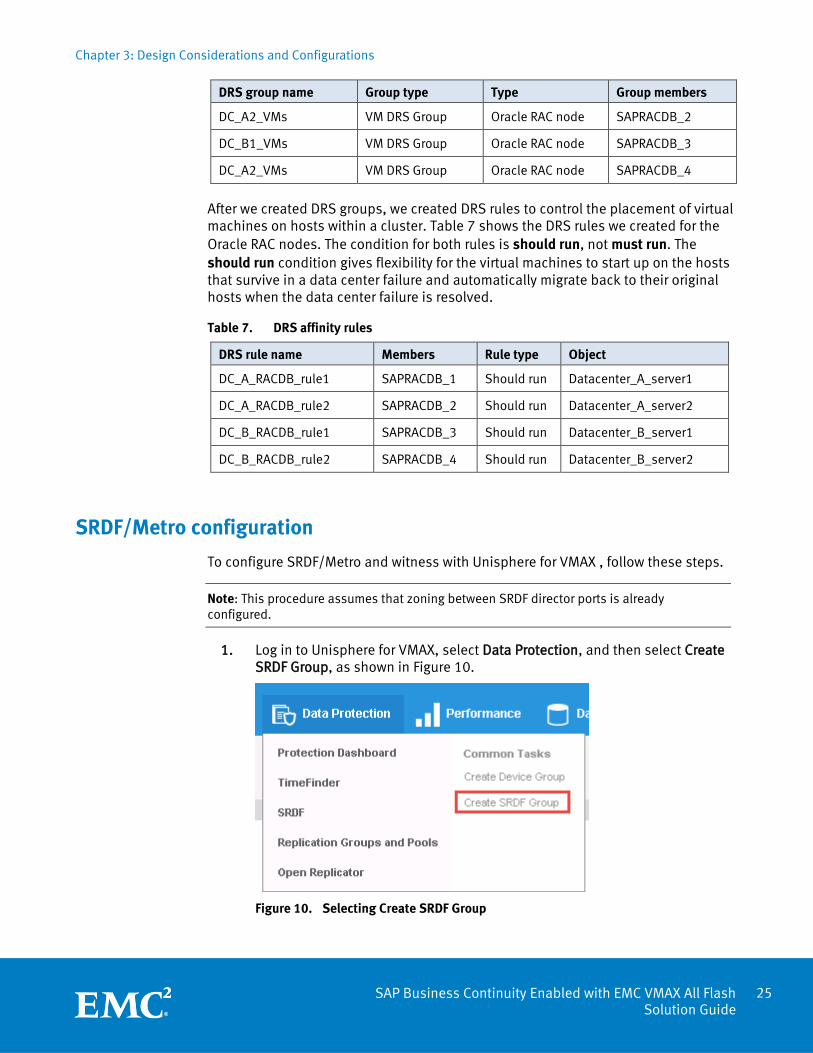
To configure SRDF/Metro and witness with Unisphere for VMAX , follow these steps.
Note: This procedure assumes that zoning between SRDF director ports is already configured.
1. Log in to Unisphere for VMAX, select Data Protection, and then select Create SRDF Group, as shown in Figure 10.
Figure 10. Selecting Create SRDF Group

Chapter 3: Design Considerations and Configurations
26 SAP Business Continuity Enabled with EMC VMAX All Flash Solution Guide
2. Create a witness SRDF group consisting of the R1 VMAX array and the witness array, as shown in Figure 11:
a. Select the SRDF director ports of the R1 array and the witness array.
b. Select SRDF/Metro Quorum Group.
Figure 11. Creating an SRDF/Metro witness group
3. Repeat the preceding step to create a witness SRDF group consisting of the R2 VMAX array and the witness array.
4. Create an SRDF group consisting of the R1 and R2 arrays, as shown in Figure 12.
Figure 12. Creating an SRDF group
Chapter 3: Design Considerations and Configurations
27 SAP Business Continuity Enabled with EMC VMAX All Flash Solution Guide
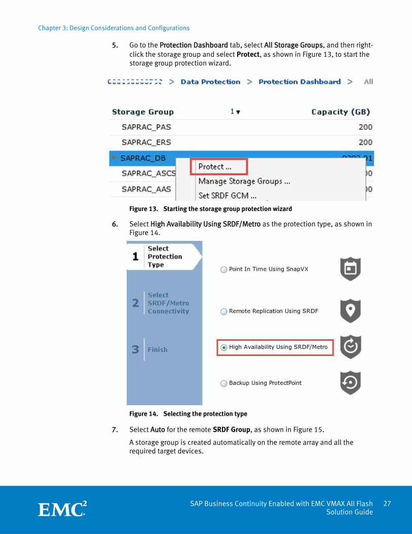
5. Go to the Protection Dashboard tab, select All Storage Groups, and then right-click the storage group and select Protect, as shown in Figure 13, to start the storage group protection wizard.
Figure 13. Starting the storage group protection wizard
6. Select High Availability Using SRDF/Metro as the protection type, as shown in Figure 14.
Figure 14. Selecting the protection type
7. Select Auto for the remote SRDF Group, as shown in Figure 15.
A storage group is created automatically on the remote array and all the required target devices.
Chapter 3: Design Considerations and Configurations
28 SAP Business Continuity Enabled with EMC VMAX All Flash Solution Guide
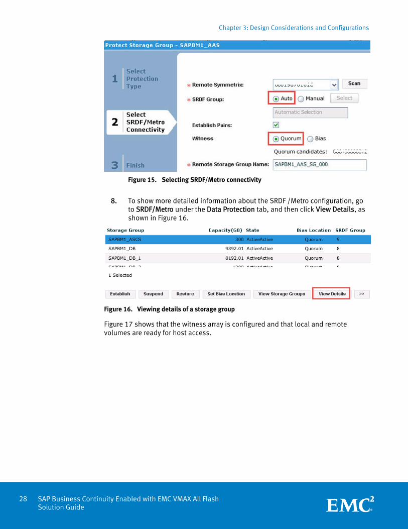
Figure 15. Selecting SRDF/Metro connectivity
8. To show more detailed information about the SRDF /Metro configuration, go to SRDF/Metro under the Data Protection tab, and then click View Details, as shown in Figure 16.
Figure 16. Viewing details of a storage group
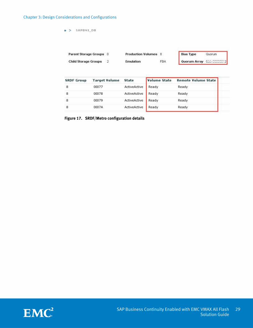
Figure 17 shows that the witness array is configured and that local and remote volumes are ready for host access.
Chapter 3: Design Considerations and Configurations
29 SAP Business Continuity Enabled with EMC VMAX All Flash Solution Guide
Figure 17. SRDF/Metro configuration details
Chapter 3: Design Considerations and Configurations
30 SAP Business Continuity Enabled with EMC VMAX All Flash Solution Guide
SAP on Oracle RAC configuration
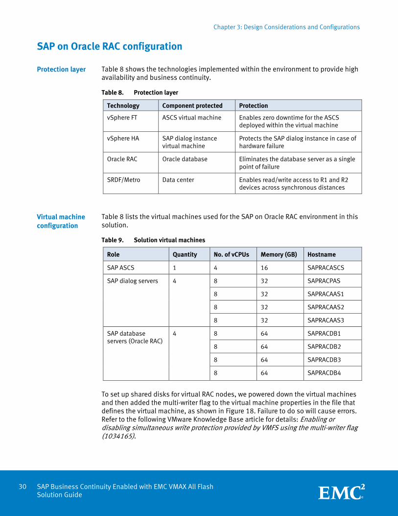
Table 8 shows the technologies implemented within the environment to provide high availability and business continuity.
Table 8. Protection layer
Technology Component protected Protection
vSphere FT ASCS virtual machine Enables zero downtime for the ASCS deployed within the virtual machine
vSphere HA SAP dialog instance virtual machine
Protects the SAP dialog instance in case of hardware failure
Oracle RAC Oracle database Eliminates the database server as a single point of failure
SRDF/Metro Data center Enables read/write access to R1 and R2 devices across synchronous distances
Table 8 lists the virtual machines used for the SAP on Oracle RAC environment in this solution.
Table 9. Solution virtual machines
Role Quantity No. of vCPUs Memory (GB) Hostname
SAP ASCS 1 4 16 SAPRACASCS
SAP dialog servers 4
8 32 SAPRACPAS
8 32 SAPRACAAS1
8 32 SAPRACAAS2
8 32 SAPRACAAS3
SAP database servers (Oracle RAC)
4 8 64 SAPRACDB1
8 64 SAPRACDB2
8 64 SAPRACDB3
8 64 SAPRACDB4
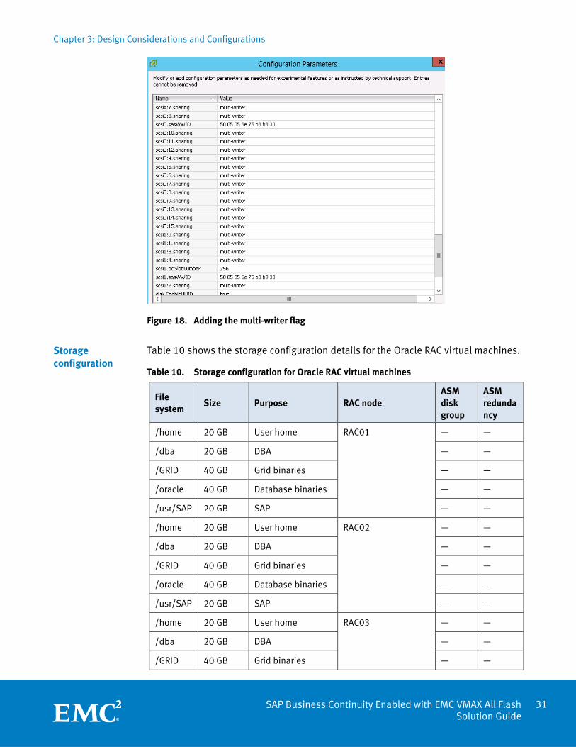
To set up shared disks for virtual RAC nodes, we powered down the virtual machines and then added the multi-writer flag to the virtual machine properties in the file that defines the virtual machine, as shown in Figure 18. Failure to do so will cause errors. Refer to the following VMware Knowledge Base article for details: Enabling or disabling simultaneous write protection provided by VMFS using the multi-writer flag (1034165).
Protection layer
Virtual machine configuration
Chapter 3: Design Considerations and Configurations
31 SAP Business Continuity Enabled with EMC VMAX All Flash Solution Guide
Figure 18. Adding the multi-writer flag
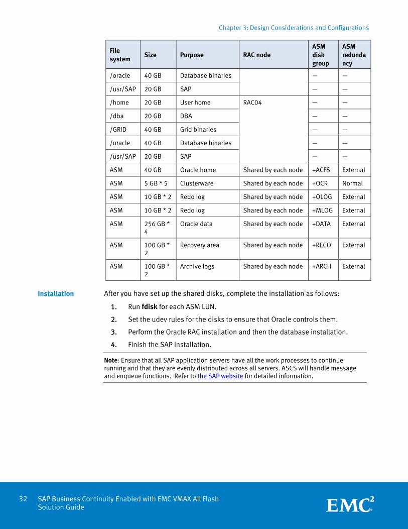
Table 10 shows the storage configuration details for the Oracle RAC virtual machines.
Table 10. Storage configuration for Oracle RAC virtual machines
File system
Size Purpose RAC node ASM disk group
ASM redundancy
/home 20 GB User home RAC01
— —
/dba 20 GB DBA — —
/GRID 40 GB Grid binaries — —
/oracle 40 GB Database binaries — —
/usr/SAP 20 GB SAP — —
/home 20 GB User home RAC02
— —
/dba 20 GB DBA — —
/GRID 40 GB Grid binaries — —
/oracle 40 GB Database binaries — —
/usr/SAP 20 GB SAP — —
/home 20 GB User home RAC03
— —
/dba 20 GB DBA — —
/GRID 40 GB Grid binaries — —
Storage configuration
Chapter 3: Design Considerations and Configurations
32 SAP Business Continuity Enabled with EMC VMAX All Flash Solution Guide
File system
Size Purpose RAC node ASM disk group
ASM redundancy
/oracle 40 GB Database binaries — —
/usr/SAP 20 GB SAP — —
/home 20 GB User home RAC04
— —
/dba 20 GB DBA — —
/GRID 40 GB Grid binaries — —
/oracle 40 GB Database binaries — —
/usr/SAP 20 GB SAP — —
ASM 40 GB Oracle home Shared by each node +ACFS External
ASM 5 GB * 5 Clusterware Shared by each node +OCR Normal
ASM 10 GB * 2 Redo log Shared by each node +OLOG External
ASM 10 GB * 2 Redo log Shared by each node +MLOG External
ASM 256 GB * 4
Oracle data Shared by each node +DATA External
ASM 100 GB * 2
Recovery area Shared by each node +RECO External
ASM 100 GB * 2
Archive logs Shared by each node +ARCH External
After you have set up the shared disks, complete the installation as follows:
1. Run fdisk for each ASM LUN.
2. Set the udev rules for the disks to ensure that Oracle controls them.
3. Perform the Oracle RAC installation and then the database installation.
4. Finish the SAP installation.
Note: Ensure that all SAP application servers have all the work processes to continue running and that they are evenly distributed across all servers. ASCS will handle message and enqueue functions. Refer to the SAP website for detailed information.
Installation
Chapter 4: Test and Validation
33 SAP Business Continuity Enabled with EMC VMAX All Flash Solution Guide
Chapter 4 Test and Validation
This chapter presents the following topics:
Overview ............................................................................................................... 34
Planned ESXi host maintenance ............................................................................. 34
Data center failure with a single-instance Oracle database..................................... 37
Data center failure in an Extended Oracle RAC environment .................................... 42
Chapter 4: Test and Validation
34 SAP Business Continuity Enabled with EMC VMAX All Flash Solution Guide
Overview
This chapter describes the tests we performed to validate SAP application live migration during planned maintenance across data centers, and SRDF/Metro protection of SAP applications with a single-instance Oracle database and Extended Oracle RAC. This chapter describes the following scenarios:
Planned ESXi host maintenance
Data center failure with a single-instance Oracle database
Data center failure in an Extended Oracle RAC environment
Planned ESXi host maintenance
Planned maintenance can include hardware maintenance, hypervisor maintenance, installation of patches, and upgrades of the server BIOS, drives, and the hypervisor itself. These activities could cause application downtime. This solution enables SAP or other workloads to be moved across data centers without downtime due to a planned event.
For this scenario, we ran the SAP workload described in SAP Power Benchmark. To test the scenario, we enabled maintenance mode of all ESXi hosts of Data Center A in vSphere Web Client. This test scenario demonstrates SAP application live migration across data centers, as shown in Figure 19.
Introduction
Chapter 4: Test and Validation
35 SAP Business Continuity Enabled with EMC VMAX All Flash Solution Guide
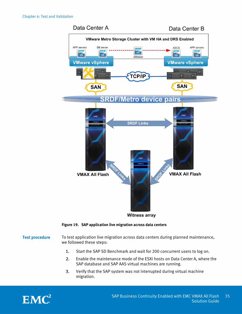
Figure 19. SAP application live migration across data centers
To test application live migration across data centers during planned maintenance, we followed these steps:
1. Start the SAP SD Benchmark and wait for 200 concurrent users to log on.
2. Enable the maintenance mode of the ESXi hosts on Data Center A, where the SAP database and SAP AAS virtual machines are running.
3. Verify that the SAP system was not interrupted during virtual machine migration.
Test procedure
Chapter 4: Test and Validation
36 SAP Business Continuity Enabled with EMC VMAX All Flash Solution Guide
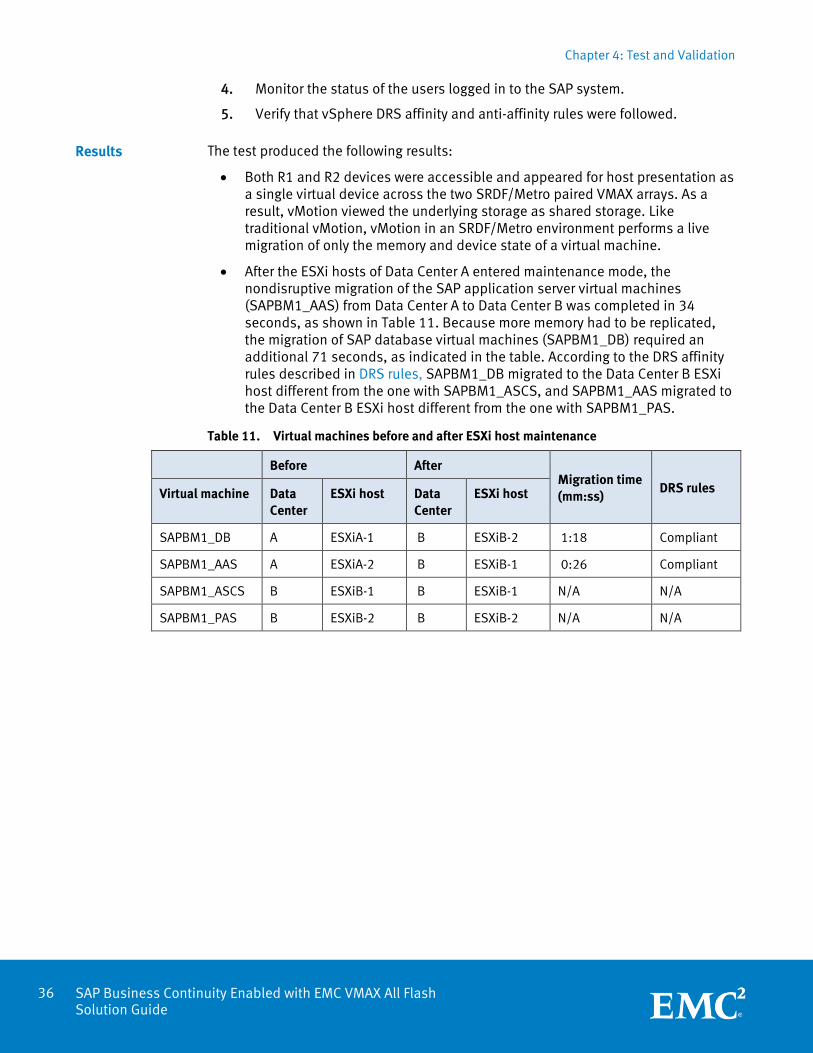
4. Monitor the status of the users logged in to the SAP system.
5. Verify that vSphere DRS affinity and anti-affinity rules were followed.
The test produced the following results:
Both R1 and R2 devices were accessible and appeared for host presentation as a single virtual device across the two SRDF/Metro paired VMAX arrays. As a result, vMotion viewed the underlying storage as shared storage. Like traditional vMotion, vMotion in an SRDF/Metro environment performs a live migration of only the memory and device state of a virtual machine.
After the ESXi hosts of Data Center A entered maintenance mode, the nondisruptive migration of the SAP application server virtual machines (SAPBM1_AAS) from Data Center A to Data Center B was completed in 34 seconds, as shown in Table 11. Because more memory had to be replicated, the migration of SAP database virtual machines (SAPBM1_DB) required an additional 71 seconds, as indicated in the table. According to the DRS affinity rules described in DRS rules, SAPBM1_DB migrated to the Data Center B ESXi host different from the one with SAPBM1_ASCS, and SAPBM1_AAS migrated to the Data Center B ESXi host different from the one with SAPBM1_PAS.
Table 11. Virtual machines before and after ESXi host maintenance
Before After Migration time (mm:ss)
DRS rules Virtual machine Data Center
ESXi host Data Center
ESXi host
SAPBM1_DB A ESXiA-1 B ESXiB-2 1:18 Compliant
SAPBM1_AAS A ESXiA-2 B ESXiB-1 0:26 Compliant
SAPBM1_ASCS B ESXiB-1 B ESXiB-1 N/A N/A
SAPBM1_PAS B ESXiB-2 B ESXiB-2 N/A N/A
Results
Chapter 4: Test and Validation
37 SAP Business Continuity Enabled with EMC VMAX All Flash Solution Guide
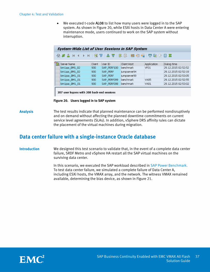
We executed t-code AL08 to list how many users were logged in to the SAP system. As shown in Figure 20, while ESXi hosts in Data Center A were entering maintenance mode, users continued to work on the SAP system without interruption.
Figure 20. Users logged in to SAP system
The test results indicate that planned maintenance can be performed nondisruptively and on demand without affecting the planned downtime commitments on current service level agreements (SLAs). In addition, vSphere DRS affinity rules can dictate the placement of the virtual machines during migration.
Data center failure with a single-instance Oracle database
We designed this test scenario to validate that, in the event of a complete data center failure, SRDF Metro and vSphere HA restart all the SAP virtual machines on the surviving data center.
In this scenario, we executed the SAP workload described in SAP Power Benchmark. To test data center failure, we simulated a complete failure of Data Center A, including ESXi hosts, the VMAX array, and the network. The witness VMAX remained available, determining the bias device, as shown in Figure 21.
Analysis
Introduction
Chapter 4: Test and Validation
38 SAP Business Continuity Enabled with EMC VMAX All Flash Solution Guide
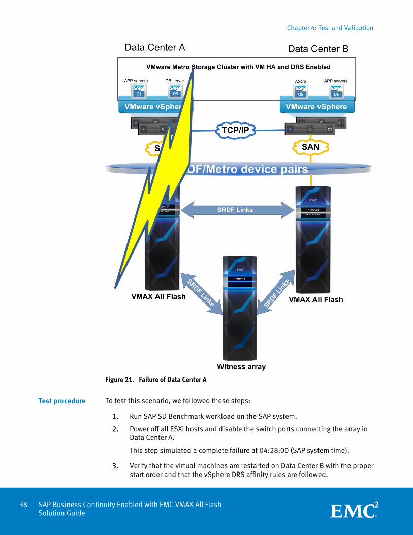
Figure 21. Failure of Data Center A
To test this scenario, we followed these steps:
1. Run SAP SD Benchmark workload on the SAP system.
2. Power off all ESXi hosts and disable the switch ports connecting the array in Data Center A.
This step simulated a complete failure at 04:28:00 (SAP system time).
3. Verify that the virtual machines are restarted on Data Center B with the proper start order and that the vSphere DRS affinity rules are followed.
Test procedure
Chapter 4: Test and Validation
39 SAP Business Continuity Enabled with EMC VMAX All Flash Solution Guide
4. Verify that the SAP system is started automatically on Data Center B, and record the duration of the SAP service downtime.
5. Verify that no data loss occurred by checking the VBAP table in the SAP system on Data Center B.
6. Re-run the SAP SD Benchmark with 600 concurrent users for 10 hours to simulate post-failover workload.
7. Power on all ESXi hosts and enable switch ports of Data Center A to simulate a restore of the data center.
8. Establish the suspended SRDF/Metro link.
The test showed the following:
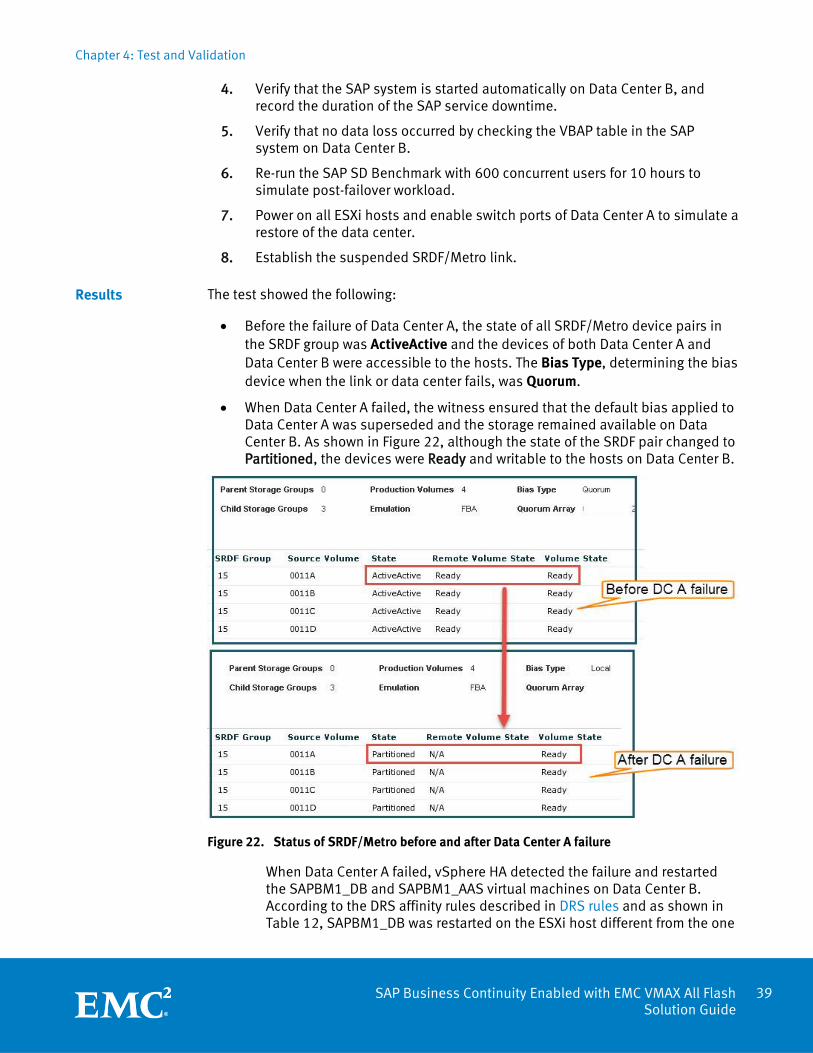
Before the failure of Data Center A, the state of all SRDF/Metro device pairs in the SRDF group was ActiveActive and the devices of both Data Center A and Data Center B were accessible to the hosts. The Bias Type, determining the bias device when the link or data center fails, was Quorum.
When Data Center A failed, the witness ensured that the default bias applied to Data Center A was superseded and the storage remained available on Data Center B. As shown in Figure 22, although the state of the SRDF pair changed to Partitioned, the devices were Ready and writable to the hosts on Data Center B.
Figure 22. Status of SRDF/Metro before and after Data Center A failure
When Data Center A failed, vSphere HA detected the failure and restarted the SAPBM1_DB and SAPBM1_AAS virtual machines on Data Center B. According to the DRS affinity rules described in DRS rules and as shown in Table 12, SAPBM1_DB was restarted on the ESXi host different from the one
Results
Chapter 4: Test and Validation
40 SAP Business Continuity Enabled with EMC VMAX All Flash Solution Guide
with SAPBM1_ASCS, and SAPBM1_AAS was restarted on the ESXi host different from the one with SAPBM1_PAS.
Table 12. Virtual machines before and after Data Center A failure
Before Data Center A failure
After Data Center A failure
DRS rules
vSphere HA restart duration (mm:ss)
Service outage duration (mm:ss)
Virtual machine Data Center
ESXi host Data Center
ESXi host
SAPBM1_DB A ESXiA-1 B ESXiB-2 Compliant 1:22 3:59
SAPBM1_AAS A ESXiA-2 B ESXiB-1 Compliant 0:47 4:21
SAPBM1_ASCS B ESXiB-1 B ESXiB-1 N/A N/A N/A
SAPBM1_PAS B ESXiB-2 B ESXiB-2 N/A N/A N/A
During the startup of the virtual machines, the SAP instance was started automatically by a script, as described in Auto-start of SAP instances. The SAP service outage duration was less than 5 minutes.
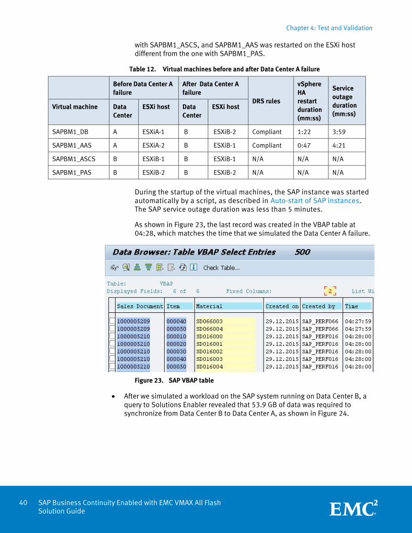
As shown in Figure 23, the last record was created in the VBAP table at 04:28, which matches the time that we simulated the Data Center A failure.
Figure 23. SAP VBAP table
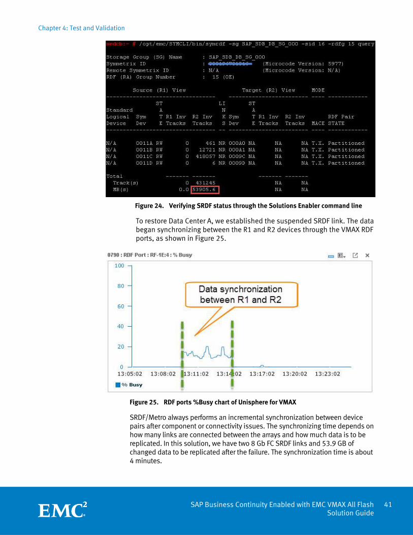
After we simulated a workload on the SAP system running on Data Center B, a query to Solutions Enabler revealed that 53.9 GB of data was required to synchronize from Data Center B to Data Center A, as shown in Figure 24.
Chapter 4: Test and Validation
41 SAP Business Continuity Enabled with EMC VMAX All Flash Solution Guide
Figure 24. Verifying SRDF status through the Solutions Enabler command line
To restore Data Center A, we established the suspended SRDF link. The data began synchronizing between the R1 and R2 devices through the VMAX RDF ports, as shown in Figure 25.
Figure 25. RDF ports %Busy chart of Unisphere for VMAX
SRDF/Metro always performs an incremental synchronization between device pairs after component or connectivity issues. The synchronizing time depends on how many links are connected between the arrays and how much data is to be replicated. In this solution, we have two 8 Gb FC SRDF links and 53.9 GB of changed data to be replicated after the failure. The synchronization time is about 4 minutes.
Chapter 4: Test and Validation
42 SAP Business Continuity Enabled with EMC VMAX All Flash Solution Guide
This test showed that the SAP instance restarted quickly and automatically on Data Center B without any data loss after the failure of Data Center A. vSphere DRS affinity rules controlled the placement of the virtual machines on the surviving data center. The SRDF/Metro performs an incremental synchronization after the data center failure.
Data center failure in an Extended Oracle RAC environment
A highly available SAP system requires:
Data availability across data centers using shared storage
Oracle RAC
SAP ASCS with vSphere FT
SAP dialog instances across data centers using vSphere HA
Data availability across data centers using shared storage
SRDF/Metro provides the data availability across the data centers to all the ESXi hosts. Storage in both data centers appear as shared storage across the two SRDF paired arrays for host presentation.
Oracle RAC
In an Extended Oracle RAC configuration, two or more RAC nodes reside in separate data centers. These RAC nodes access the same data that is present in each data center. An SAP node does not access any one node directly; instead, it connects via the Single Client Access Name (SCAN) reference provided during the time of installation.
SAP ASCS with vSphere FT
The purpose of the ASCS instance is to listen for new connections to the SAP instance and to ensure that consistent writes are made to the database via its enqueue process. The enqueue process administers the lock table in the shared memory. The lock table contains the logical database locks of the ABAP runtime environment of the SAP system. Each system requires only one enqueue work process.
The ASCS instance should be made highly available as well. The use of an ASCS virtual machine protected by vSphere FT enables the virtual machine to fail over to an available data center without interruption of service.
SAP dialog instances across data centers using vSphere HA
The SAP application servers, PAS and AAS, are spread across both data centers and can accept active workloads from either location. When an SAP dialog instance starts up, the work processes establish a connection to the database—sometimes referred to as a shadow work process. This is just a persistent Oracle session (1-to-1 relationship). The SAP application server will also use vSphere HA in case of a data center failure, but a failure will still have some impact on the end user. The SAP dialog server on the failed data center will break a connection between the dialog users and the database. You must restart the SAP application servers from the failed site on the surviving site to permit new user requests.
Analysis
Introduction
Chapter 4: Test and Validation
43 SAP Business Continuity Enabled with EMC VMAX All Flash Solution Guide
We carried out the following failure scenarios to demonstrate the elimination of single points of failure from the environment:
Failure of the RAC node
Failure of the RAC interconnect network
Failure of an ASCS virtual machine
Failure of a data center
This test scenario validates the following in the event of an unexpected RAC node failure:
The surviving node remains operational, maintaining all connections to the SAP instance.
The system remains functional in a business capacity.
Scenario
We performed an operating-system-level halt on one RAC node on a single ESXi host.
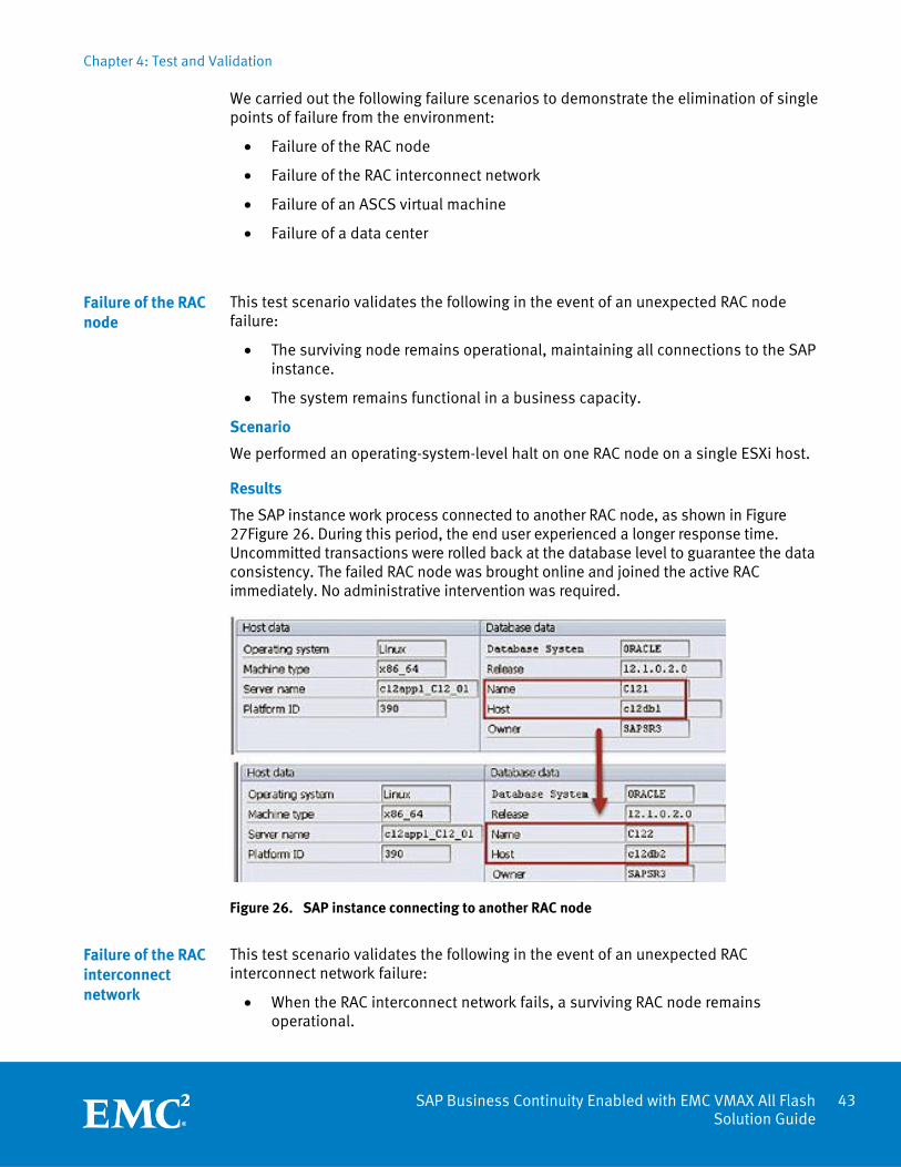
Results
The SAP instance work process connected to another RAC node, as shown in Figure 27Figure 26. During this period, the end user experienced a longer response time. Uncommitted transactions were rolled back at the database level to guarantee the data consistency. The failed RAC node was brought online and joined the active RAC immediately. No administrative intervention was required.
Figure 26. SAP instance connecting to another RAC node
This test scenario validates the following in the event of an unexpected RAC interconnect network failure:
When the RAC interconnect network fails, a surviving RAC node remains operational.
Failure of the RAC node
Failure of the RAC interconnect network
Chapter 4: Test and Validation
44 SAP Business Continuity Enabled with EMC VMAX All Flash Solution Guide
Scenario
We disabled ports used by the RAC interconnect on IP switches.
Results
The database continued operations on a single RAC node. During this period, the end user experienced a longer response time. Uncommitted transactions were rolled back at the database level to guarantee the data consistency. When the network was reconnected, the RAC node joined automatically. No administrative intervention was required.
This test scenario validates that vSphere FT enables zero downtime for the SAP application in the event of an unexpected ASCS virtual machine failure.
Scenario
We powered off the ESXi host on which the ASCS virtual machine was located.
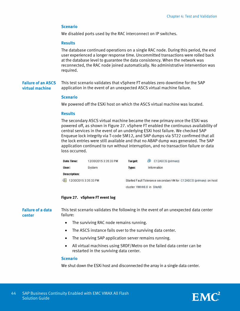
Results
The secondary ASCS virtual machine became the new primary once the ESXi was powered off, as shown in Figure 27. vSphere FT enabled the continuous availability of central services in the event of an underlying ESXi host failure. We checked SAP Enqueue lock integrity via T-code SM12, and SAP dumps via ST22 confirmed that all the lock entries were still available and that no ABAP dump was generated. The SAP application continued to run without interruption, and no transaction failure or data loss occurred.
Figure 27. vSphere FT event log
This test scenario validates the following in the event of an unexpected data center failure:
The surviving RAC node remains running.
The ASCS instance fails over to the surviving data center.
The surviving SAP application server remains running.
All virtual machines using SRDF/Metro on the failed data center can be restarted in the surviving data center.
Scenario
We shut down the ESXi host and disconnected the array in a single data center.
Failure of an ASCS virtual machine
Failure of a data center
Chapter 4: Test and Validation
45 SAP Business Continuity Enabled with EMC VMAX All Flash Solution Guide
Results
As expected, users connected to the SAP application server on the surviving node experienced no impact. The users connected to the SAP application server on the failed data center lost their session. As a result of using vSphere HA, the failed application server and Oracle RAC node restarted on the surviving data center. The application server started accepting connections after about 3 minutes and the database node restarted and joined the RAC automatically after 5 minutes.
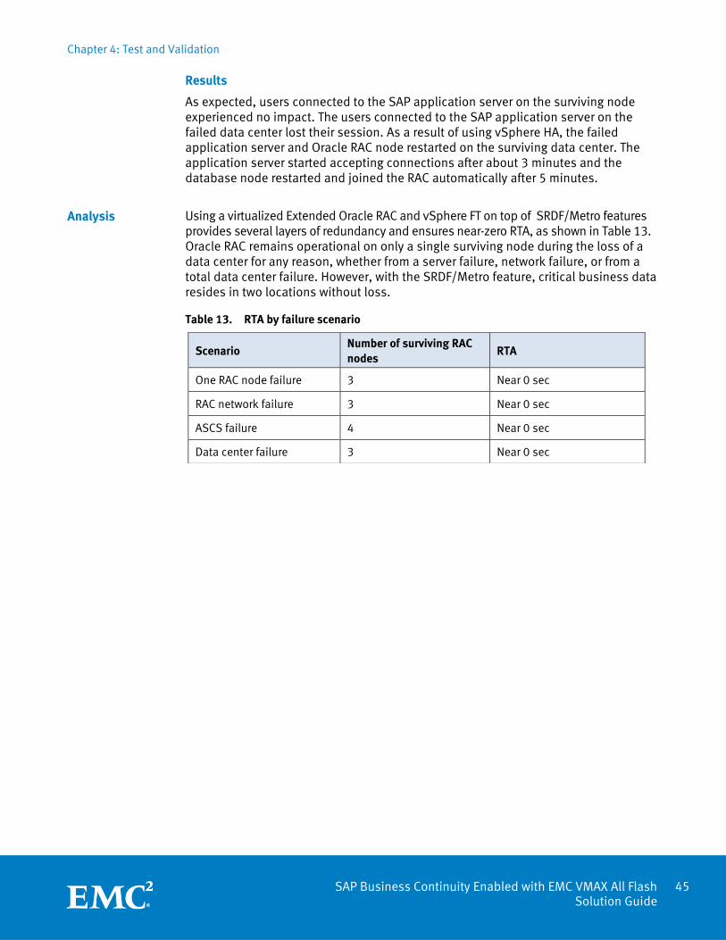
Using a virtualized Extended Oracle RAC and vSphere FT on top of SRDF/Metro features provides several layers of redundancy and ensures near-zero RTA, as shown in Table 13. Oracle RAC remains operational on only a single surviving node during the loss of a data center for any reason, whether from a server failure, network failure, or from a total data center failure. However, with the SRDF/Metro feature, critical business data resides in two locations without loss.
Table 13. RTA by failure scenario
Analysis
Scenario Number of surviving RAC nodes
RTA
One RAC node failure 3 Near 0 sec
RAC network failure 3 Near 0 sec
ASCS failure 4 Near 0 sec
Data center failure 3 Near 0 sec
Chapter 5: Conclusion
46 SAP Business Continuity Enabled with EMC VMAX All Flash Solution Guide
Chapter 5 Conclusion
This chapter presents the following topics:
Summary ............................................................................................................... 47
Chapter 5: Conclusion
47 SAP Business Continuity Enabled with EMC VMAX All Flash Solution Guide
Summary
With VMAX All Flash, SRDF/Metro, vSphere HA, and vSphere DRS in a vMSC configuration, this solution provides the following benefits for SAP applications:
Offers the best performance and scalability
Enables SAP system high availability across local and remote data centers
Minimizes downtime in the event of a data center failure
Enables SAP application live migration across data centers without interruption
vSphere HA can restart SAP instances within a few minutes of a complete data center failure. Business-critical SAP applications can be moved live and within seconds to a remote data center outside the area to be affected by a planned outage. System administrators can proactively avoid the impact of a planned outage to preserve the availability of the business-critical SAP applications.
In addition, Extended Oracle RAC over SRDF/Metro provides these benefits:
Enables flexibility for the RAC environment across datacenters
With shared virtual machine disks (VMDKs), RAC nodes can reside in either data center in a VMAX All Flash environment that is configured for SRDF/Metro. RAC nodes can be moved (via vMotion) to the other arrays or data centers to accommodate activities such as planned maintenance of the ESXi host, network, or storage array.
Enables database-layer high availability across local and remote data centers
Distributed workload across data centers enables a degree of fault tolerance during an outage. The surviving data center will still have an active RAC node.
Distributes user workloads across data centers
Users can connect to SAP application servers at one or both locations, which can alleviate uneven workload distributions across data centers.
Performs Oracle rolling upgrades to the database based on Oracle methodologies (for information, see http://docs.oracle.com/cd/B28359_01 /install.111/b28263/procstop.htm)
Upgrade operations can be completed on one RAC node at a time, minimizing planned downtime.
Eliminates ongoing Oracle licensing costs
Databases are used effectively, and RAC nodes can be moved from failed to surviving data centers to maintain the distributed workload. Multiple nodes for each data center and licensing commitments are not required.
Chapter 6: References
48 SAP Business Continuity Enabled with EMC VMAX All Flash Solution Guide
Chapter 6 References
This chapter presents the following topics:
EMC documentation ............................................................................................... 49
SAP documentation ............................................................................................... 49
VMware documentation ......................................................................................... 49
Oracle documentation ............................................................................................ 49
Chapter 6: References
49 SAP Business Continuity Enabled with EMC VMAX All Flash Solution Guide
EMC documentation
For additional information, see the following white papers, which are available on EMC.com:
Introduction to SRDF/Metro: EMC Engineering White Paper
EMC Mission-Critical Business Continuity for SAP White Paper
Frequently Asked Questions: VMAX All Flash
Announcing VMAX All Flash with Latest 3D NAND Technology
SAP documentation
For additional information, see the following SAP documents:
SAP Note 1122388—Linux: VMware vSphere configuration guidelines
SAP Note 1122387—Linux: SAP Support in virtualized environments
SAP Note 1122388—Linux: VMware vSphere configuration guidelines
SAP Note 1915323 - OS User Concept for Oracle Database 12c Release 1
SAP Note 1915299 - Troubleshooting Software Installation for 12.1.0.2
SAP Note 2229934 - Oracle 12c RAC with Oracle ASM in Stretched Clusters
VMware documentation
For additional information, see the following VMware documents:
SAP Solutions on VMware Best Practices Guide
SAP Solutions on VMware Business Continuance: Protecting Against Unplanned Downtime
Enabling or disabling simultaneous write protection provided by VMFS using the multi-writer flag (1034165)
Deploying a Metro Storage Cluster across two data centers using EMC VMAX SRDF/Metro and VMware vSphere (2134684)
VMware vSphere 6 Fault Tolerance Architecture and Performance
Oracle documentation
For additional information, see the following Oracle documents:
Configuring Storage for Oracle Grid Infrastructure for a Cluster and Oracle RAC
Oracle Real Application Clusters on Extended Distance Clusters