Embed Size (px)
Citation preview

Emerging Trends inIntegrated Motor Systems
Demand Side Energy Consultant Inc.Alex Fleming, P.Eng.– Principal
#psf11
Markus Zeller, P.Eng.– BC Hydro

Presentation Outline• Integrated Motor Systems and Energy Use• Trends and Opportunities
– Component Efficiency– Premium Control– Energy Engineering– Application Engineering
• System Energy Performance• Closing the Gap
Early Adopters Early/Late
Majority LaggardsInnovators

Electric Motor Energy Usage
50% of total electricity consumed in BC isconverted to shaft power in motor driven systems:
Large(>500 hp),
23%
Medium(1-500 hp),
68%
Small(< 1 hp),
9%
Medium(1-500 hp),
11%
Small(< 1 hp),
89%
0%
20%
40%
60%
80%
100%
%-Energy %-Units

Efficient conveyorcomponents can boostsystem efficiency, but not improve thebasis of design.
Component Efficiency has an Impact
ηConveyor system = ηMotor X ηBelt X ηReducer X ηChain X ηdragchain
Component 30% = 0.904 x 0.95 x 0.55 x 0.90 x 0.70
EE Component 54% = 0.942 x 0.97 x 0.94 x 0.90 x 0.70

Limits and Diminishing Returnsin Motor Component Efficiency
70
75
80
85
90
95
100
- 50 100 150 200 250 300 350 400 450 500Rating (hp)
Full
Load
Effi
cien
cy (%
)
Super Premium
2010
19971994

Premium Control
The ‘load’ is a process and the motor system boundary is now crossed
Allows equipment to follow the load and maintain the Best Efficiency Point (BEP)over an operating range

Premium Control
Chart courtesy of CEATI
Complicates component efficiency predictions
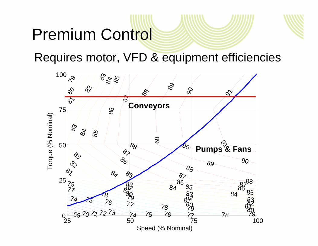
Premium Control
69 70 71 72 73 74
74
75
75
76
76
77
77
77
7878
78
79
7979
79
79
80
8080
80
81
8181
81
81
82
8282
82
82
83
83
8383
83
83
84
84
84
8484
85
85
85
8585
86
86
8686
87
87
8787
8888
88
88
8989
89
90
90
90
91
91
Speed (% Nominal)
Torq
ue (%
Nom
inal
)
25 50 75 1000
25
50
75
100
Conveyors
Pumps & Fans
Requires motor, VFD & equipment efficiencies

Premium ControlPlus any minimum pressure requirementneeds modified ‘Laws of Affinity’
3
1
min
1
2
1
min
1
2 1
H
HQQ
HH
PowerPower
2
1
min
1
2
1
min
1
2 1
H
HQQ
HH
HeadHead
1
min
1
2
1
min
1
2 1H
HQQ
HH
SpeedSpeed

Five Motor System Opportunities
ACTIVITY APPROACH MOTOR SYSTEM OBJECTIVE
Catalogue Engineering
Remove and replace (R&R) Low Distraction/TransactionLow Cost/Low Risk
Go to E.E. Catalogue
Install energy efficient components
Improve Component Efficiency
PremiumControl
Load match the supply side with process demands
Achieve Best Efficiency Points
EnergyEngineering
Optimize supply side efficiency with demand-side consideration
Optimize PerformanceReduce components
Application Engineering
Integrated Motor Systems –OEM Industrial Appliances
Re-visit the Basis of DesignIntegrated Energy Mgt System
Premium Control and EE Components comprise majority of present activity

Power Smart Pump Video

Five Motor System Opportunities
ACTIVITY APPROACH MOTOR SYSTEM OBJECTIVE
Catalogue Engineering
Remove and replace (R&R) Low Distraction/TransactionLow Cost/Low Risk
Go to E.E. Catalogue
Install energy efficient components
Improve Component Efficiency
PremiumControl
Load match the supply side with process demands
Achieve Best Efficiency Points
EnergyEngineering
Optimize supply side efficiency with demand-side consideration
Optimize PerformanceReduce components
Application Engineering
Integrated Motor Systems –OEM Industrial Appliances
Re-visit the Basis of DesignIntegrated Energy Mgt System

Energy/Application Engineering • Basis of Design – Packaged unit with lowest
risks and lowest total cost of ownership– High speed motor with magnetic bearings– Oil-free variable speed compressor– Off-load power lowest in industry– Half weight and size– Low maintenance– Low noise– But what’s in the box?

What is an Integrated Motor System?An electric motor driven system that serves theprocess application efficiently and effectivelyas well as addresses the design intent
Integrated Fan Motor All-electric LNG PlantSystem (30 Watts) (4 motors, 260 MW)

The Trend is Toward the‘On-Demand’ Appliances• OEM go back to basis of design. • Variable capacity and intelligent control. • Packaged ‘system knowledge’• ‘Other Benefits’ noise, footprint, reliability.
+ =

Application Engineering Commercial HVAC ApplianceVariable Refrigeration Volume (VRV) is more than variable frequency drives on chillers & fans.
• Variable System output - tracks load profile and demand
• Volume regulated by electronic expansion valve
• Simultaneous heating/cooling• Ductless heating and cooling• Intelligent and Proprietary Controls

Application EngineeringIndustrial Wastewater Appliance
• High-speed blower designed for wastewater
• High speed & variable speed motor
• Balanced design – low noise, small footprint
• Intelligent & Proprietary Controls
• Energy performance metric is kWh per kg of BOD removed
High Speed Turbo Blower …..Just add electricity and piping

Multi‐StageTurbo
Induction Motor Geared
Single Stage Turbo
Performance
Induction MotorMagnetic Bearing
Direct DriveSingle Stage
Turbo
PM MotorFoil BearingDirect Drive
Stainless Steel ImpellerSingle Stage Turbo
Bellows P.D.
Price
Photos courtesy of KTurbo Inc.
High Speed Turbo Blowers

Industrial Appliance DesignStarts with the process requirement and the basis of design, then considers the mostappropriate integrated motor system options.

How to ID Application Engineering• A renewed ‘basis-of-design’, fully integrated,
definite purpose, plug & play.• Re-engineered as an appliance package with
embedded specific algorithms and controls.• Energy performance is based upon its
process function - not just efficiency. – kWh per unit of process outcome

Examples: Integrated Motor Systems
• Energy Efficient Components• Premium Control• Energy Engineering• Application Engineering
Early Adopters
Early/Late Majority
LaggardsInnovators

Gearless Mill Drives
VSDHigh
Speed
VSDLow
SpeedVSDGMD
Transformer 99.1% 99.1% 99.1%Converter 98.6% 98.6% 99.2%Motor 97.2% 97.2% 96.8%Gear Reducer 98.5% n/a n/aRing-gear 98.0% 98.0% n/aOverallEfficiency 91.7% 93.1% 95.2%
Basis of Design:• very large (16MW), low-speed, variable speed

Motorized Pulleys• Basis of Design:
– Integrated design– Sealed unit– Low maintenance

Motor Shaft Load Shaft
Constant Speed Direct Drive Coupling• Basis of Design:
– Small speed reductions can result in large energy savings– Fixed speed tuning for centrifugal loads (similar to sheaves)– Reversed by removing shims (impeller trim is not reversible)– Isolate pump from motor (alignment & vibration)
Photos courtesy of MagnaDrive Inc.

Integrated Fan Motor Systems• Basis of Design:
– Greenhouse ventilation & control– Energy savings (60-80%)– Variable speed

Direct Drive Cooling Tower Fan ?

Dust Extraction Technology• Basis of Design:
– Eliminates baghouse filter system by encapsulating the dust particles into atomized water
– Removes abrasive dust particles out of air stream– No reduction in performance under high dust loads– High dust collection efficiencies– Compact high volume design– Low maintenance– Self cleaning
Photos courtesy of Engart Global .

Electro-Mechanical Actuators• Basis of Design:
– Eliminate pneumatic or hydraulic completely– Improved control & reliability

Same Fish Growth with 60% less waterWell pump energy reduced by 50%
Site energy consumption reduced by 25%
Fish Hatchery Raceway Recirc.

Performance
Application Engineering for Dry Kilns
ConventionalKiln
HighEfficiency Kiln
PremiumEfficiency Kiln
ProgressiveKiln
Electricity 0.16 kWh/kg 20-25% savings 30-50% savings >50% savings
Thermal 5.0 MJ/kg 10-15% savings 20-30% savings >30% savings

Next Steps: Closing the Gap -System versus Components
– Standardized system boundaries of unit process function
– Baseline and benchmarking protocols

Next Steps: Closing the Gap -System versus Components• Development of process specific energy
performance metrics are critical:• Ability of field measurement for energy
performance verification and diagnostic:

Impacts on Codes & StandardsShift from the energy efficient components to system energy performance requires:
– Definitions: Efficiency versus Effectiveness– Scope: System Boundaries and Load Profiles– M&V: Process Specific Energy Performance – EnMS: Energy Management System

Thank You!
Demand Side Energy Consultants1-800 [email protected]
Alex Fleming, P.Eng. – Principal
#psf11