Embed Size (px)
Citation preview
EMULATING THE DIRECT BLISTER FURNACE (DBF) PROCESS WITH COAL
COMBUSTION CAPABILITIES IN
STAR-CCM+ V4.06
joint development venture between
Bateman & Aerotherm
2010 STAR European Conference: 22 & 23 March, London, UK
2
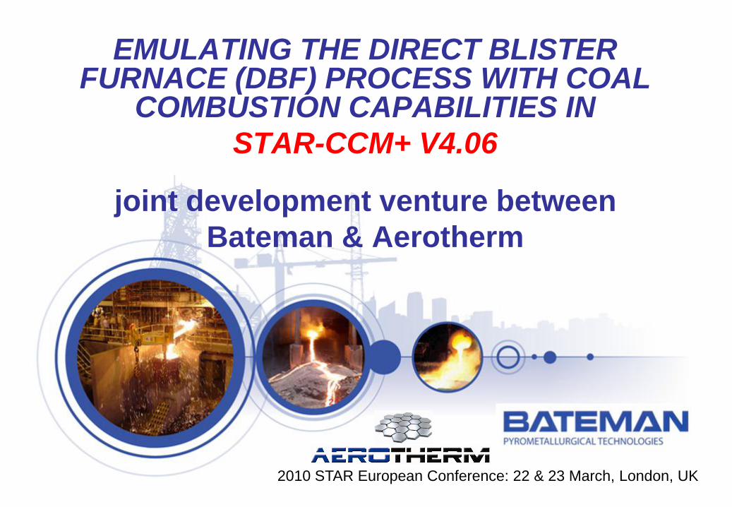
CONTENTS
• Numerical Model Details - DBF.
• Boundary Conditions - DBF.
• Direct Blister Furnace – Phase One.
• US / Throat / WHB – Phase Two.
• Way Forward.
• Conclusions.
• Questions.
3
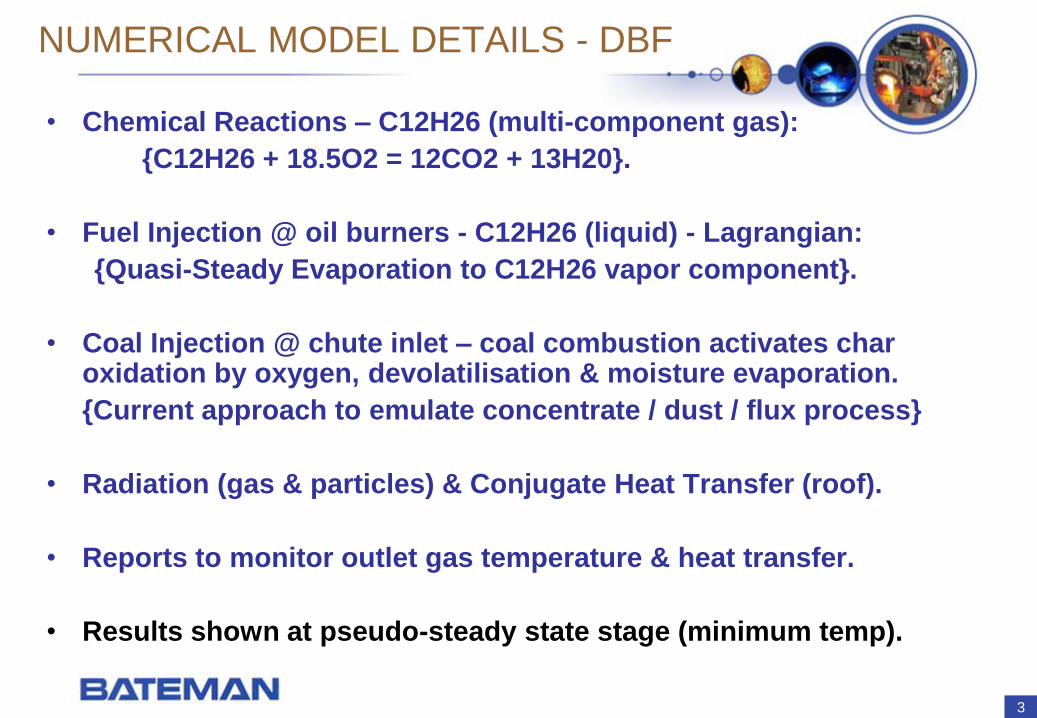
NUMERICAL MODEL DETAILS - DBF
• Chemical Reactions – C12H26 (multi-component gas):
{C12H26 + 18.5O2 = 12CO2 + 13H20}.
• Fuel Injection @ oil burners - C12H26 (liquid) - Lagrangian:
{Quasi-Steady Evaporation to C12H26 vapor component}.
• Coal Injection @ chute inlet – coal combustion activates char oxidation by oxygen, devolatilisation & moisture evaporation.
{Current approach to emulate concentrate / dust / flux process}
• Radiation (gas & particles) & Conjugate Heat Transfer (roof).
• Reports to monitor outlet gas temperature & heat transfer.
• Results shown at pseudo-steady state stage (minimum temp).
4
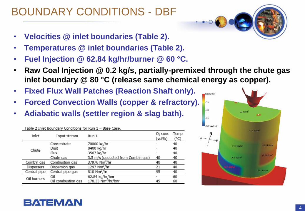
BOUNDARY CONDITIONS - DBF
• Velocities @ inlet boundaries (Table 2).
• Temperatures @ inlet boundaries (Table 2).
• Fuel Injection @ 62.84 kg/hr/burner @ 60 °C.
• Raw Coal Injection @ 0.2 kg/s, partially-premixed through the chute gas
inlet boundary @ 80 °C (release same chemical energy as copper).
• Fixed Flux Wall Patches (Reaction Shaft only).
• Forced Convection Walls (copper & refractory).
• Adiabatic walls (settler region & slag bath).
5
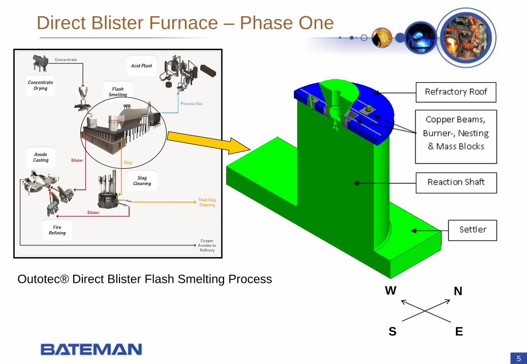
Direct Blister Furnace – Phase One
NW
S E
Outotec® Direct Blister Flash Smelting Process
6
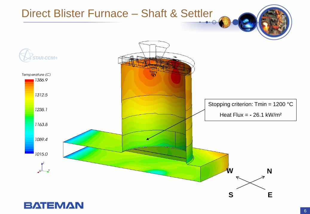
Direct Blister Furnace – Shaft & Settler
NW
S E
Stopping criterion: Tmin = 1200 °C
Heat Flux = - 26.1 kW/m²
7
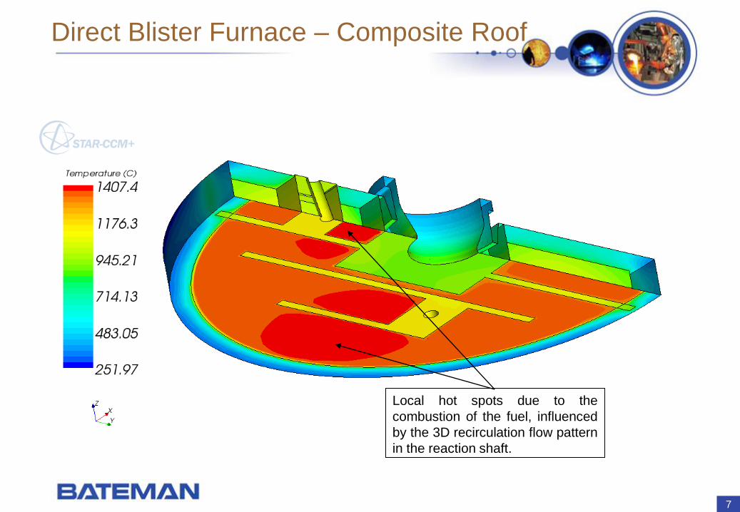
Direct Blister Furnace – Composite Roof
Local hot spots due to the
combustion of the fuel, influenced
by the 3D recirculation flow pattern
in the reaction shaft.
8
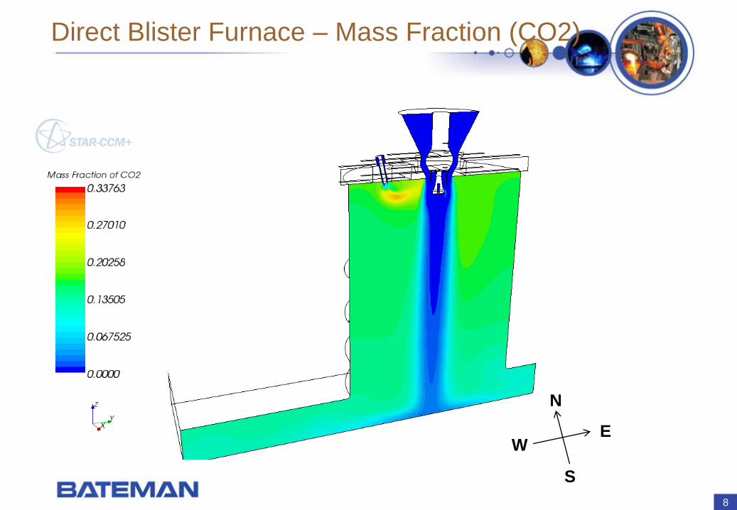
Direct Blister Furnace – Mass Fraction (CO2)
N
W
S
E
9
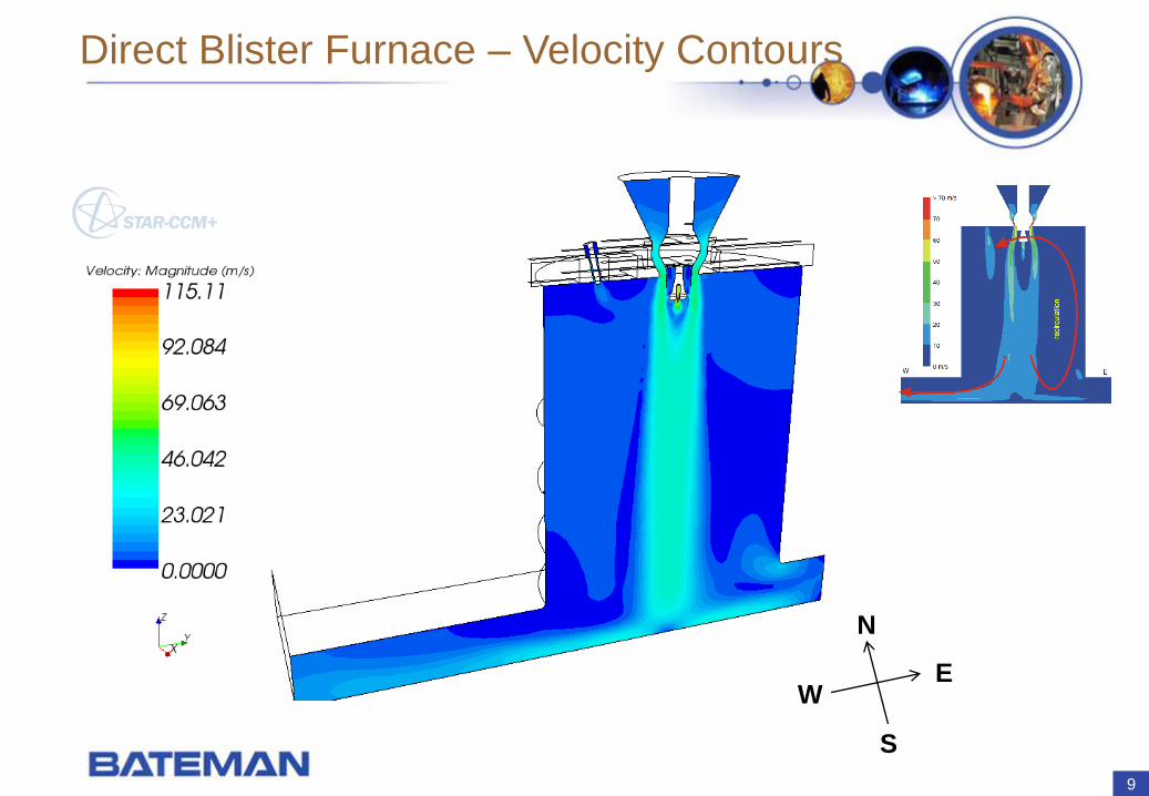
Direct Blister Furnace – Velocity Contours
N
W
S
E
10
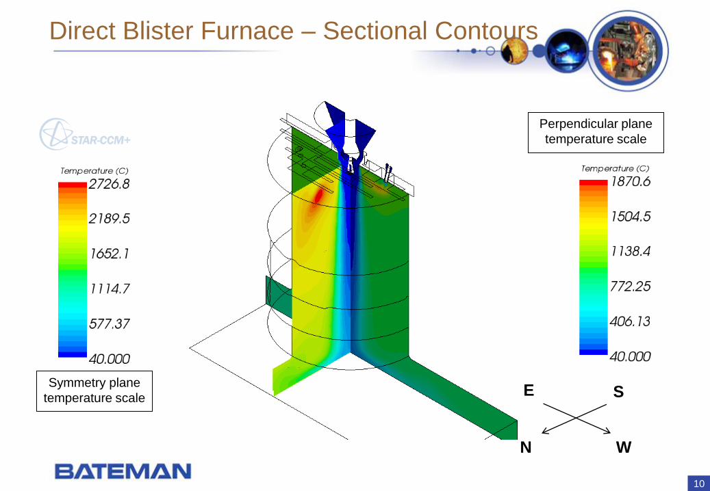
Direct Blister Furnace – Sectional Contours
W
S
N
ESymmetry plane
temperature scale
Perpendicular plane
temperature scale
11
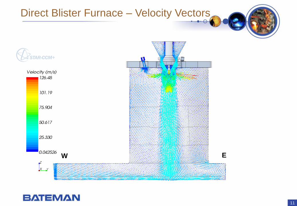
Direct Blister Furnace – Velocity Vectors
W E
12
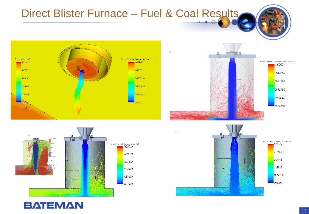
Direct Blister Furnace – Fuel & Coal Results
13
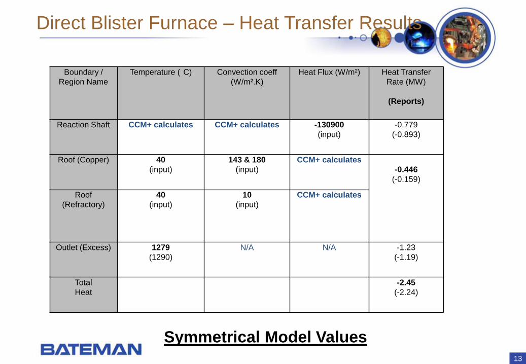
Direct Blister Furnace – Heat Transfer Results
Boundary /
Region Name
Temperature ( C) Convection coeff
(W/m².K)
Heat Flux (W/m²) Heat Transfer
Rate (MW)
(Reports)
Reaction Shaft CCM+ calculates CCM+ calculates -130900
(input)
-0.779
(-0.893)
Roof (Copper) 40
(input)
143 & 180
(input)
CCM+ calculates
-0.446
(-0.159)
Roof
(Refractory)
40
(input)
10
(input)
CCM+ calculates
Outlet (Excess) 1279
(1290)
N/A N/A -1.23
(-1.19)
Total
Heat
-2.45
(-2.24)
Symmetrical Model Values
14
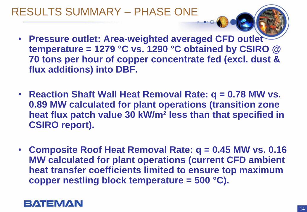
RESULTS SUMMARY – PHASE ONE
• Pressure outlet: Area-weighted averaged CFD outlet temperature = 1279 °C vs. 1290 °C obtained by CSIRO @ 70 tons per hour of copper concentrate fed (excl. dust & flux additions) into DBF.
• Reaction Shaft Wall Heat Removal Rate: q = 0.78 MW vs. 0.89 MW calculated for plant operations (transition zone heat flux patch value 30 kW/m² less than that specified in CSIRO report).
• Composite Roof Heat Removal Rate: q = 0.45 MW vs. 0.16 MW calculated for plant operations (current CFD ambient heat transfer coefficients limited to ensure top maximum copper nestling block temperature = 500 °C).
15
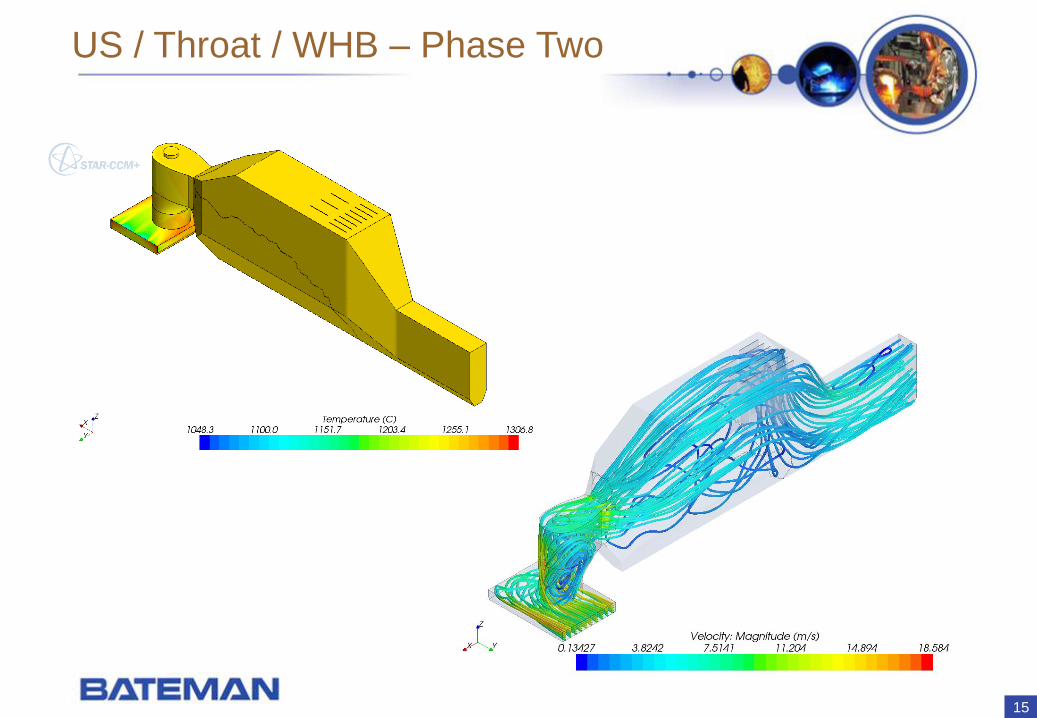
US / Throat / WHB – Phase Two
16
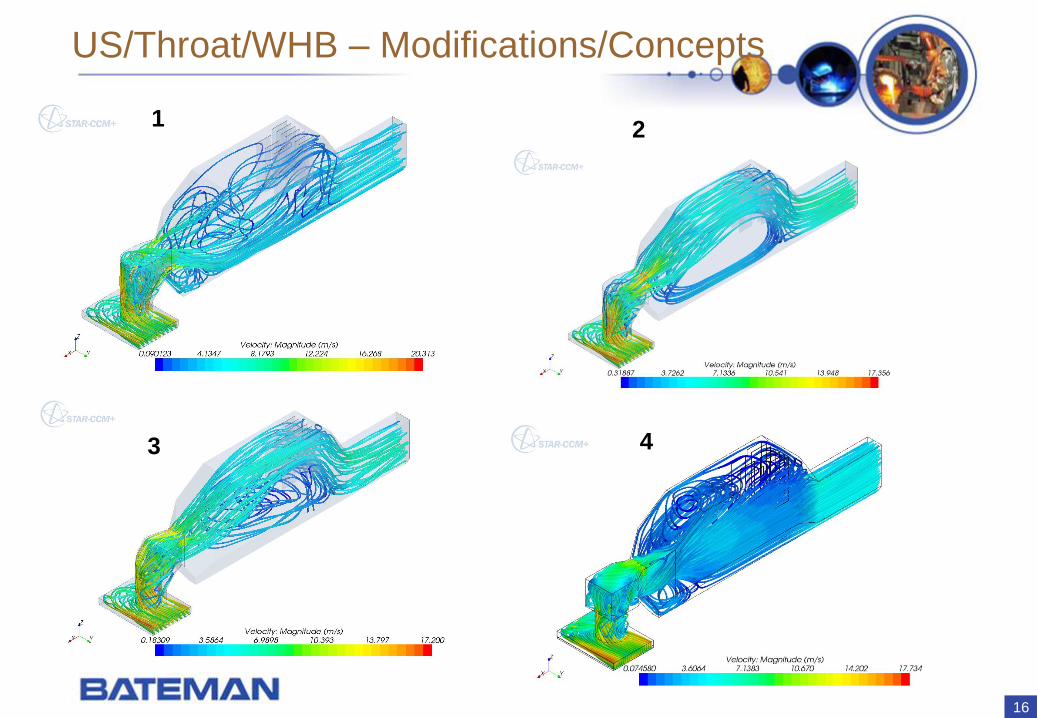
US/Throat/WHB – Modifications/Concepts
2
3 4
1
17
WAY FORWARD
• Incorporate copper sulphide concentrate / dust / flux reaction kinetics data & all properties for the DBF: obtaining necessary info from client (March 2010).
• Uptake Shaft, Throat & Waste Heat Boiler simulated separately - mapping CFD results obtained @ Reaction Shaft outlet onto inlet of 2nd CFD model (project started: February 2010 for coal combustion outlet results).
• STAR-CCM+ v4.06 enabled us to emulate the copper concentrate DBF process on the interim with pulverised coal combustion. Aim downstream: apply more accurate hot face temperatures and heat transfer coefficients to design better furnace containment equipment.
18
CONCLUSIONS
• Developed DBF numerical model for CFD purposes.
• Fluid Flow Initialised. Added Chemical Reactions, Fuel Injection & Radiation sequentially (numerical stability).
• COAL combustion capability applied to emulate copper concentrate / dust / flux energy release with calculated coal mass flow rate in DBF (fixed coal composition).
• STAR-CCM+ applied to emulate real process with latest pulverised coal combustion capability successfully.
• Transferred symmetrical DBF outlet data to full WHB model inlet to analyse fluid flow & improve possibly.
19
ACKNOWLEDGEMENTS
AEROTHERM (SA):
Martin van Staden, Julius Cloete & David Mentz.
CD-adapco (USA):
Piyush Thakre & Rajesh Rawat.
20
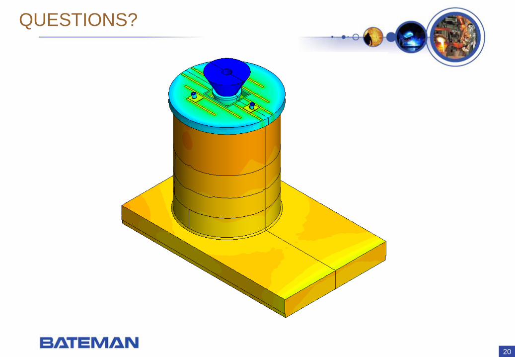
QUESTIONS?