Embed Size (px)
Citation preview
Technical Manual
EN
NLC60HZ. 17.05. 4037260_00
PUMP KIT WATER TANKCERTIFICATION 60Hz LOWNOISE VERSION
REFRIGERANT GAS
NETWORK OPERATION
COOLING ONLY MODBUS COMPATIBLE
SCROLL COMPRESSOR
PLUG FAN INTERNET CONNECTIONS
PLATE EXCHANGER
FOR TWO PIPES PLANTS
HEAT RECOVERY
• HIGH EFFICIENCY ALSO AT PARTIAL LOADS• COOLING CIRCUIT WITH CASING• COMPLETE AIR FLOW VERSATILITY• HIGH EFFICIENCY PLUG-FANS• NIGHT MODE
NLC

Dear Customer,Thank you for choosing an AERMEC product. This product is the result of many years of experience and in-depth engineering research, and it is built using top quality materials and advanced technologies.In addition, the applied mark guarantees that our appliances fully comply with the safety requirements defined by the applicable product’s rules. We constantly monitor the quality level, and as a result AERMEC products are synonymous with Safety, Quality, and Reliability.
Aermec reserves the right to make all modification deemed necessary for improving the product at any time with any modification of technical data.
Thank you again.AERMEC S.p.A

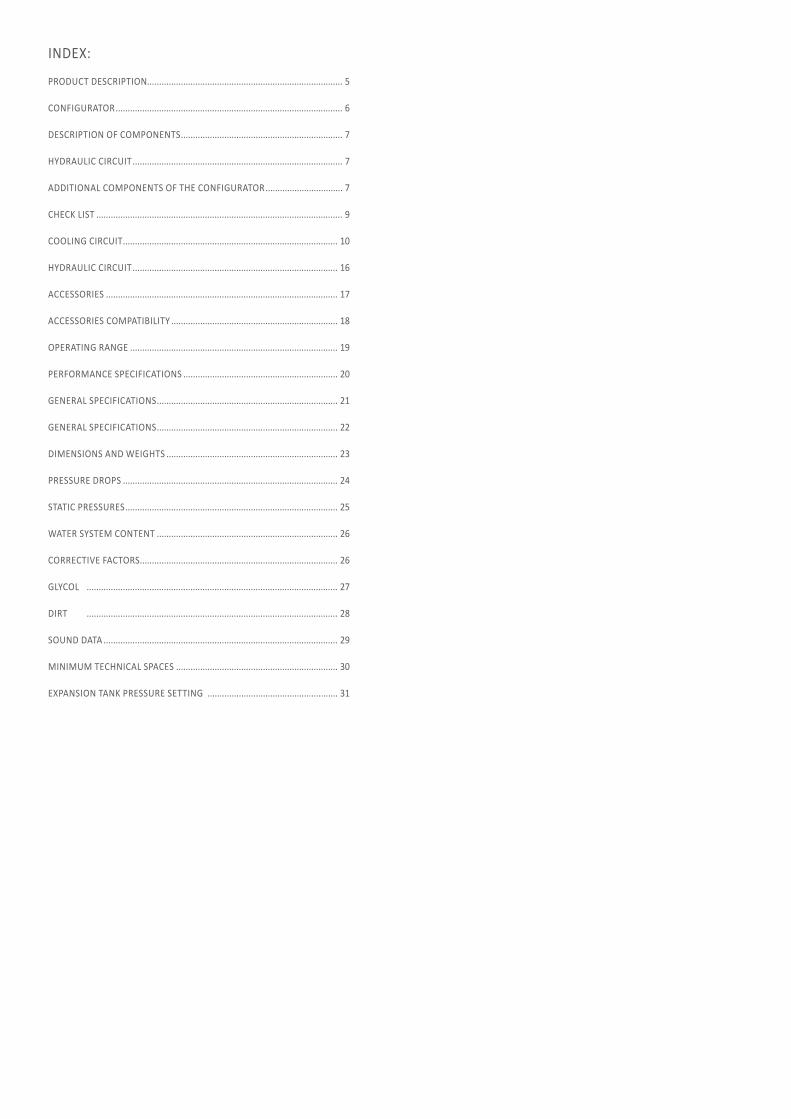
INDEX:
PRODUCT DESCRIPTION................................................................................. 5
CONFIGURATOR .............................................................................................. 6
DESCRIPTION OF COMPONENTS ................................................................... 7
HYDRAULIC CIRCUIT ....................................................................................... 7
ADDITIONAL COMPONENTS OF THE CONFIGURATOR ................................ 7
CHECK LIST ...................................................................................................... 9
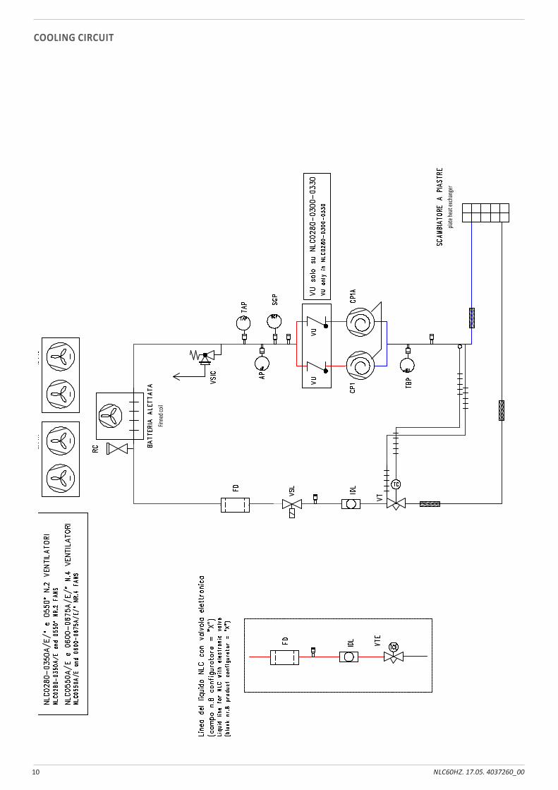
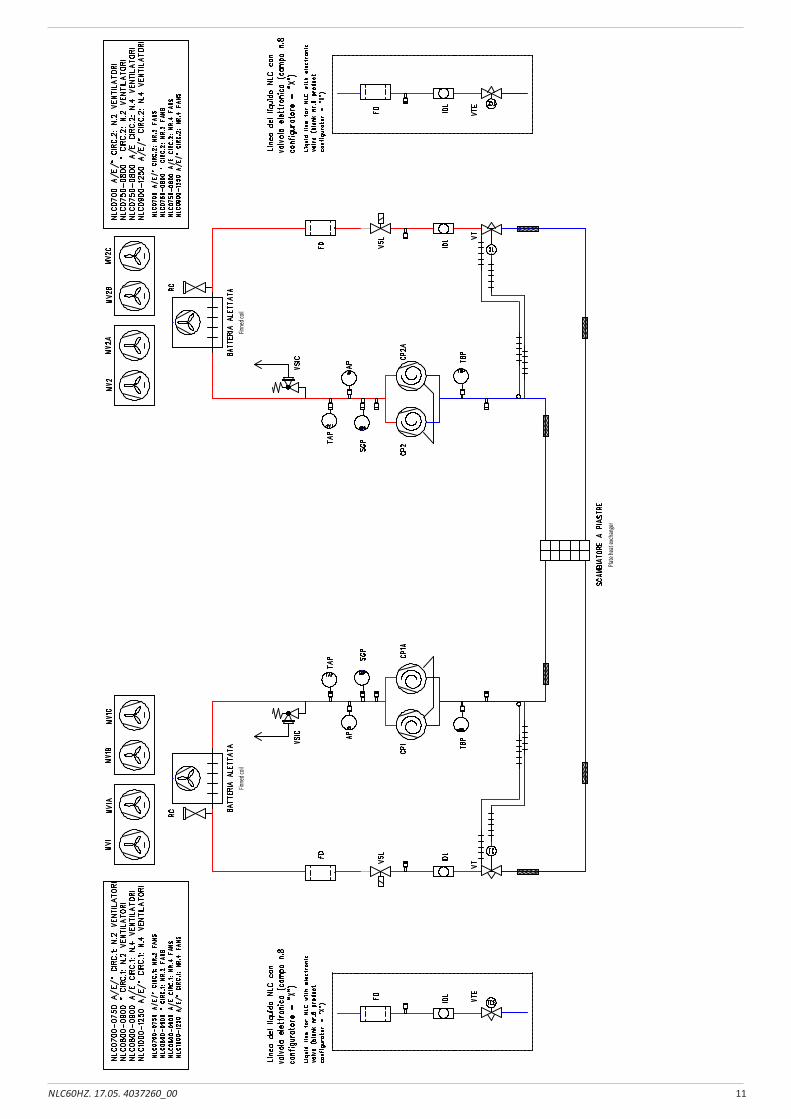
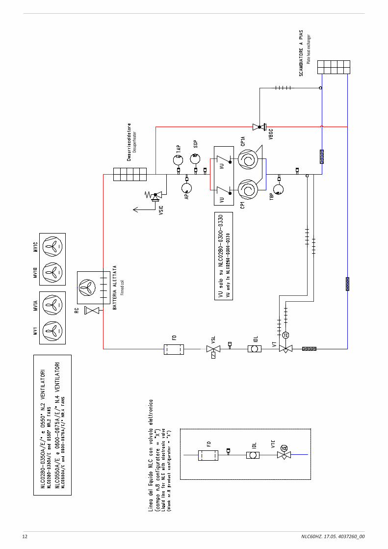
COOLING CIRCUIT ......................................................................................... 10
HYDRAULIC CIRCUIT ..................................................................................... 16
ACCESSORIES ................................................................................................ 17
ACCESSORIES COMPATIBILITY ..................................................................... 18
OPERATING RANGE ...................................................................................... 19
PERFORMANCE SPECIFICATIONS ................................................................ 20
GENERAL SPECIFICATIONS ........................................................................... 21
GENERAL SPECIFICATIONS ........................................................................... 22
DIMENSIONS AND WEIGHTS ....................................................................... 23
PRESSURE DROPS ......................................................................................... 24
STATIC PRESSURES ........................................................................................ 25
WATER SYSTEM CONTENT ........................................................................... 26
CORRECTIVE FACTORS.................................................................................. 26
GLYCOL ........................................................................................................ 27
DIRT ........................................................................................................ 28
SOUND DATA ................................................................................................. 29
MINIMUM TECHNICAL SPACES ................................................................... 30
EXPANSION TANK PRESSURE SETTING ...................................................... 31
5NLC60HZ. 17.05. 4037260_00
PRODUCT DESCRIPTION
NLC is a single or dual refrigerant circuit chiller charged with R410a gas. It has directly coupled plug fans with an EC inverter motor to ensure the quietest possible machine operation, scroll compressors with a high yield and low electricity absorption, a plate heat exchanger and a finned coil. The machine cools water to supply the distribution system that is usually connected to fan coil type terminals. In addition, NLC can also produce hot water if it is fitted with a desuperheater or total recovery system, so it’s ideal for residential and commercial contexts. It can be equipped with a hydronic kit including an expansion tank, safety valve (water side) and drain valve.
VersionsNLC_A High efficiency
The range includes units with two single circuit compressors and units with four compressors divided into two independent circuits.
The possibility of using the electronic thermostatic valve brings significant benefits, especially when the unit is working at partial loads to the benefit of the energy efficiency of the unit.
Possibility of integrated hydronic kit that encloses the main hydraulic components; it is available in different configurations with one or two pumps, with different static pressures available, with or without storage tank
The units are equipped with plug-fans and inverter motors coupled directly with the fan, with the electronic condensation control as standard, which adjusts the air flow according to the actual system requirements, with benefits in terms of consumption and noise reduction. In addition, compared to conventional centrifugal fans, they do not feature belt and pulley transmission, resulting in easy flow adjustment, compactness, versatility, easy maintenance and no vibrations
Horizontal or vertical air flow, is possible to change the direction of expulsion air flow directly in work sites.
Microprocessor adjustment, with keyboard and LCD display, for easy consultation and intervention on the unit via a menu available in several languages.
Adjustment includes complete management of the alarms and their log.
The presence of a programmable timer allows setting time bands of operation and a possible second set-point
The temperature control takes place with the integral proportional logic, based on the water output temperature.
Night Mode: it is possible to set a silenced operation profile. Perfect for night operation, since it guarantees greater acoustic comfort in the evenings, and a high efficiency in the time of greater load.
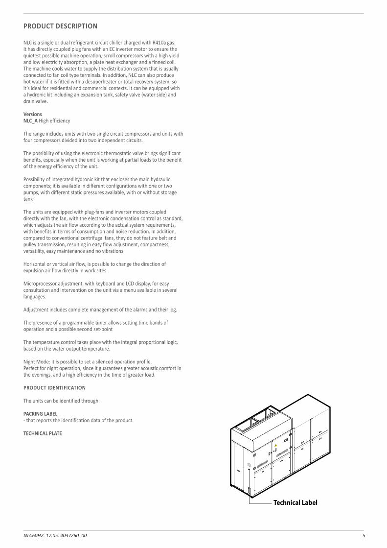
PRODUCT IDENTIFICATION
The units can be identified through:
PACKING LABEL - that reports the identification data of the product.
TECHNICAL PLATE
Technical Label
6 NLC60HZ. 17.05. 4037260_00
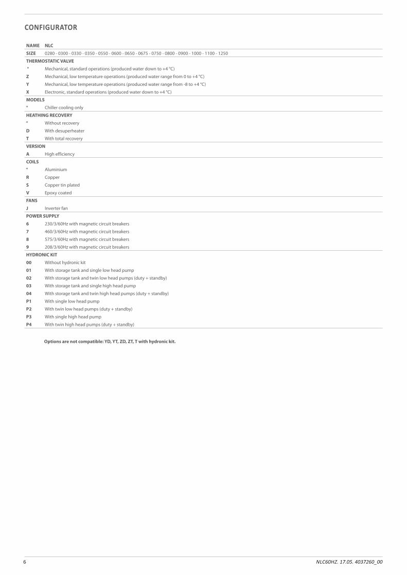
CONFIGURATOR
NAME NLC
SIZE 0280 - 0300 - 0330 - 0350 - 0550 - 0600 - 0650 - 0675 - 0750 - 0800 - 0900 - 1000 - 1100 - 1250
THERMOSTATIC VALVE
° Mechanical, standard operations (produced water down to +4 °C)
Z Mechanical, low temperature operations (produced water range from 0 to +4 °C)
Y Mechanical, low temperature operations (produced water range from -8 to +4 °C)
X Electronic, standard operations (produced water down to +4 °C)
MODELS
° Chiller cooling only
HEATHING RECOVERY
° Without recovery
D With desuperheater
T With total recovery
VERSION
A High efficiency
COILS
° Aluminium
R Copper
S Copper tin plated
V Epoxy coated
FANS
J Inverter fan
POWER SUPPLY
6 230/3/60Hz with magnetic circuit breakers
7 460/3/60Hz with magnetic circuit breakers
8 575/3/60Hz with magnetic circuit breakers
9 208/3/60Hz with magnetic circuit breakers
HYDRONIC KIT
00 Without hydronic kit
01 With storage tank and single low head pump
02 With storage tank and twin low head pumps (duty + standby)
03 With storage tank and single high head pump
04 With storage tank and twin high head pumps (duty + standby)
P1 With single low head pump
P2 With twin low head pumps (duty + standby)
P3 With single high head pump
P4 With twin high head pumps (duty + standby)
Options are not compatible: YD, YT, ZD, ZT, T with hydronic kit.
7NLC60HZ. 17.05. 4037260_00
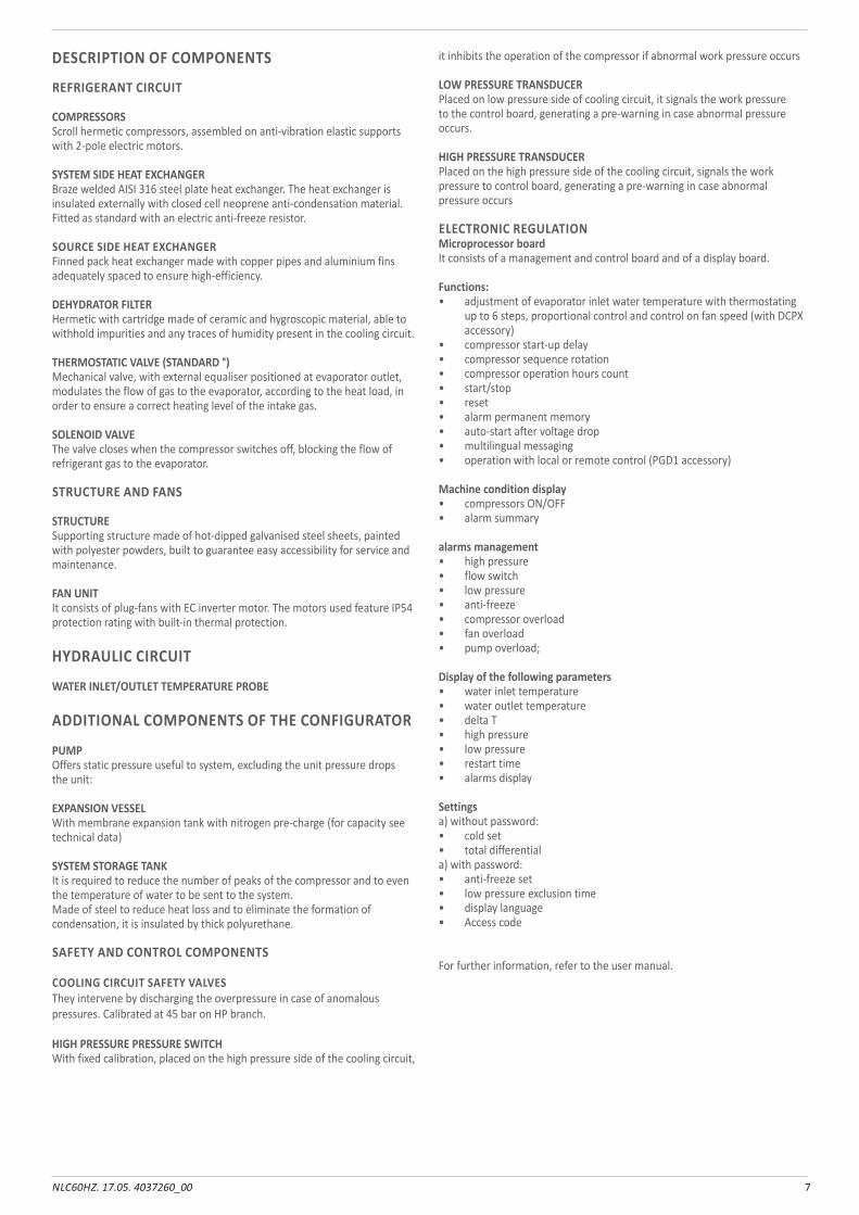
DESCRIPTION OF COMPONENTS
REFRIGERANT CIRCUIT
COMPRESSORSScroll hermetic compressors, assembled on anti-vibration elastic supports with 2-pole electric motors.
SYSTEM SIDE HEAT EXCHANGERBraze welded AISI 316 steel plate heat exchanger. The heat exchanger is insulated externally with closed cell neoprene anti-condensation material.Fitted as standard with an electric anti-freeze resistor.
SOURCE SIDE HEAT EXCHANGERFinned pack heat exchanger made with copper pipes and aluminium fins adequately spaced to ensure high-efficiency.
DEHYDRATOR FILTERHermetic with cartridge made of ceramic and hygroscopic material, able to withhold impurities and any traces of humidity present in the cooling circuit.
THERMOSTATIC VALVE (STANDARD °)Mechanical valve, with external equaliser positioned at evaporator outlet, modulates the flow of gas to the evaporator, according to the heat load, in order to ensure a correct heating level of the intake gas.
SOLENOID VALVEThe valve closes when the compressor switches off, blocking the flow of refrigerant gas to the evaporator.
STRUCTURE AND FANS
STRUCTURESupporting structure made of hot-dipped galvanised steel sheets, painted with polyester powders, built to guarantee easy accessibility for service and maintenance.
FAN UNITIt consists of plug-fans with EC inverter motor. The motors used feature IP54 protection rating with built-in thermal protection.
HYDRAULIC CIRCUIT
WATER INLET/OUTLET TEMPERATURE PROBE
ADDITIONAL COMPONENTS OF THE CONFIGURATOR
PUMPOffers static pressure useful to system, excluding the unit pressure drops the unit:
EXPANSION VESSELWith membrane expansion tank with nitrogen pre-charge (for capacity see technical data)
SYSTEM STORAGE TANK It is required to reduce the number of peaks of the compressor and to even the temperature of water to be sent to the system. Made of steel to reduce heat loss and to eliminate the formation of condensation, it is insulated by thick polyurethane.
SAFETY AND CONTROL COMPONENTS
COOLING CIRCUIT SAFETY VALVESThey intervene by discharging the overpressure in case of anomalous pressures. Calibrated at 45 bar on HP branch.
HIGH PRESSURE PRESSURE SWITCHWith fixed calibration, placed on the high pressure side of the cooling circuit,
it inhibits the operation of the compressor if abnormal work pressure occurs
LOW PRESSURE TRANSDUCERPlaced on low pressure side of cooling circuit, it signals the work pressure to the control board, generating a pre-warning in case abnormal pressure occurs.
HIGH PRESSURE TRANSDUCERPlaced on the high pressure side of the cooling circuit, signals the work pressure to control board, generating a pre-warning in case abnormal pressure occurs
ELECTRONIC REGULATIONMicroprocessor boardIt consists of a management and control board and of a display board.
Functions:• adjustment of evaporator inlet water temperature with thermostating
up to 6 steps, proportional control and control on fan speed (with DCPX accessory)
• compressor start-up delay• compressor sequence rotation• compressor operation hours count• start/stop• reset• alarm permanent memory• auto-start after voltage drop• multilingual messaging• operation with local or remote control (PGD1 accessory)
Machine condition display• compressors ON/OFF• alarm summary
alarms management• high pressure• flow switch• low pressure• anti-freeze • compressor overload• fan overload• pump overload;
Display of the following parameters• water inlet temperature• water outlet temperature• delta T• high pressure• low pressure• restart time• alarms display
Settingsa) without password:• cold set• total differentiala) with password:• anti-freeze set• low pressure exclusion time• display language• Access code
For further information, refer to the user manual.
8 NLC60HZ. 17.05. 4037260_00
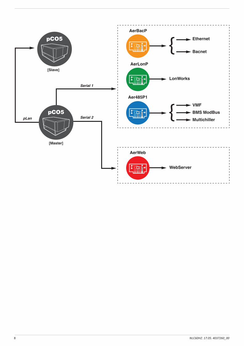
AerWeb
AerBacP
AerLonP
Aer485P1
[Master]
pCO5
[Slave]
pCO5 Ethernet
Bacnet
VMF
BMS ModBus
Multichiller
LonWorks
WebServer
pLan
Serial 1
Serial 2
9NLC60HZ. 17.05. 4037260_00
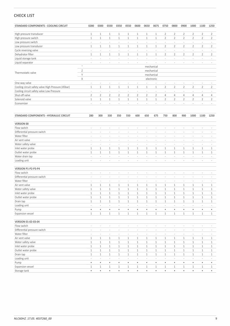
CHECK LIST
STANDARD COMPONENTS - COOLING CIRCUIT 0280 0300 0330 0350 0550 0600 0650 0675 0750 0800 0900 1000 1100 1250
High pressure transducer 1 1 1 1 1 1 1 1 2 2 2 2 2 2High pressure switch 1 1 1 1 1 1 1 1 2 2 2 2 2 2Low pressure switch - - - - - - - - - - - - - -Low pressure transducer 1 1 1 1 1 1 1 1 2 2 2 2 2 2Cycle reversing valve - - - - - - - - - - - - - -Dehydrator filter 1 1 1 1 1 1 1 1 2 2 2 2 2 2Liquid storage tank - - - - - - - - - - - - - -Liquid separator - - - - - - - - - - - - - -
Thermostatic valve
° mechanicalZ mechanicalY mechanicalX electronic
One-way valve - - - - - - - - - - - - - -Cooling circuit safety valve High Pressure (45bar) 1 1 1 1 1 1 1 1 2 2 2 2 2 2Cooling circuit safety valve Low Pressure - - - - - - - - - - - - - -Shut-off valve 2 2 2 2 2 2 2 2 4 4 4 4 4 4Solenoid valve 1 1 1 1 1 1 1 1 2 2 2 2 2 2Economizer - - - - - - - - - - - - - -
STANDARD COMPONENTS - HYDRAULIC CIRCUIT 280 300 330 350 550 600 650 675 750 800 900 1000 1100 1250
VERSION 00Flow switch - - - - - - - - - - - - - -Differential pressure switch - - - - - - - - - - - - - -Water filter - - - - - - - - - - - - - -Air vent valve - - - - - - - - - - - - - -Water safety valve - - - - - - - - - - - - - -Inlet water probe 1 1 1 1 1 1 1 1 1 1 1 1 1 1Outlet water probe 1 1 1 1 1 1 1 1 1 1 1 1 1 1Water drain tap - - - - - - - - - - - - - -Loading unit - - - - - - - - - - - - - -
VERSION P1-P2-P3-P4Flow switch - - - - - - - - - - - - - -Differential pressure switch - - - - - - - - - - - - - -Water filter - - - - - - - - - - - - - -Air vent valve 1 1 1 1 1 1 1 1 1 1 1 1 1 1Water safety valve 1 1 1 1 1 1 1 1 1 1 1 1 1 1Inlet water probe 1 1 1 1 1 1 1 1 1 1 1 1 1 1Outlet water probe 1 1 1 1 1 1 1 1 1 1 1 1 1 1Drain tap 1 1 1 1 1 1 1 1 1 1 1 1 1 1Loading unit - - - - - - - - - - - - - -Pump • • • • • • • • • • • • • •Expansion vessel 1 1 1 1 1 1 1 1 1 1 1 1 1 1
VERSION 01-02-03-04Flow switch - - - - - - - - - - - - - -Differential pressure switch - - - - - - - - - - - - - -Water filter - - - - - - - - - - - - - -Air vent valve 1 1 1 1 1 1 1 1 1 1 1 1 1 1Water safety valve 1 1 1 1 1 1 1 1 1 1 1 1 1 1Inlet water probe 1 1 1 1 1 1 1 1 1 1 1 1 1 1Outlet water probe 1 1 1 1 1 1 1 1 1 1 1 1 1 1Drain tap 1 1 1 1 1 1 1 1 1 1 1 1 1 1Loading unit - - - - - - - - - - - - - -Pump • • • • • • • • • • • • • •Expansion vessel 1 1 1 1 1 1 1 1 1 1 1 1 1 1Storage tank • • • • • • • • • • • • • •
10 NLC60HZ. 17.05. 4037260_00
NLC-
A/E/° v
ers.00
Finne
d coil
plate
heat
exch
ange
r
COOLING CIRCUIT
11NLC60HZ. 17.05. 4037260_00
NLC-
A/E/° v
ers.00
_funz
ionam
ento
RL
Finne
d coil
Finne
d coil
Plate
heat
exch
ange
r
12 NLC60HZ. 17.05. 4037260_00
NLC-
DA/D
E/D° v
ers.00
_funz
ionam
ento
RL
Finne
d coil
Desu
perhe
ater
Plate
heat
exch
ange
r
13NLC60HZ. 17.05. 4037260_00
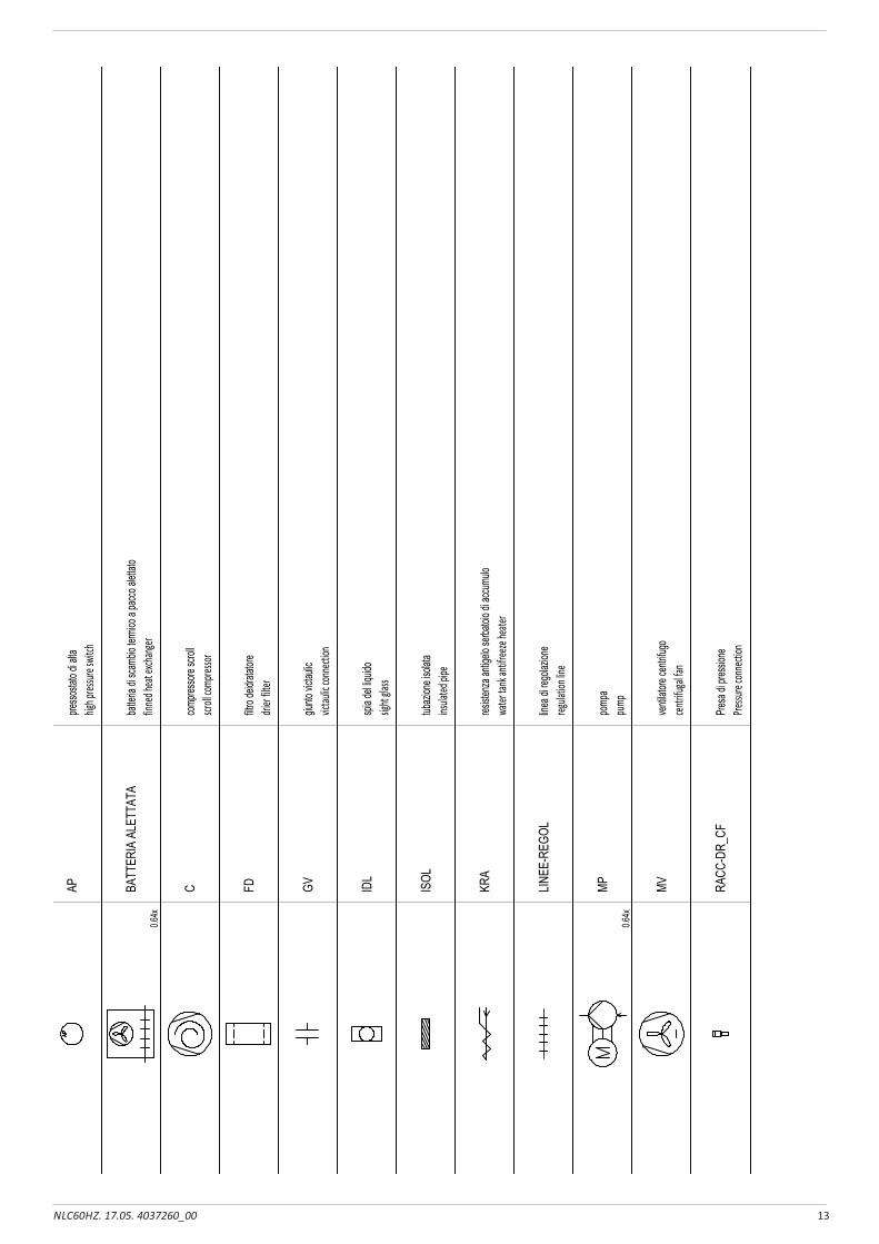
SYMB
OLS S
UMMA
RY
RIEP
ILOGO
SIMB
OLI S
CHEM
A
NOTE
:
Sym
bol
Sym
bol n
ame
FUN
ZIO
NE
NO
ME
SIM
BO
LOS
IMB
OLO
Note:
Func
tion
presso
stato
di alt
ahig
h pres
sure s
witch
AP
batte
ria di
scam
bio te
rmico
a pa
cco al
ettato
finne
d heat
excha
nger
BATT
ERIA
ALE
TTAT
A0.6
4x
comp
resso
re scr
ollscr
oll com
presso
rC
filtro d
eidrat
atore
drier
filter
FD
giunto
victau
licvic
taulic
conne
ction
GV
spia
del liq
uido
sight
glass
IDL
tubaz
ione i
solat
ains
ulated
pipe
ISOL
resiste
nza a
ntige
lo se
rbatoi
o di a
ccumu
lowa
ter ta
nk an
tifree
ze he
ater
KRA
linea d
i rego
lazion
ereg
ulatio
n line
LINEE
-REG
OL
pomp
apu
mpMP
0.64x
venti
latore
centr
ifugo
centrif
ugal f
anMV
Presa
di pr
essio
nePre
ssure
conne
ction
RACC
-DR_
CF
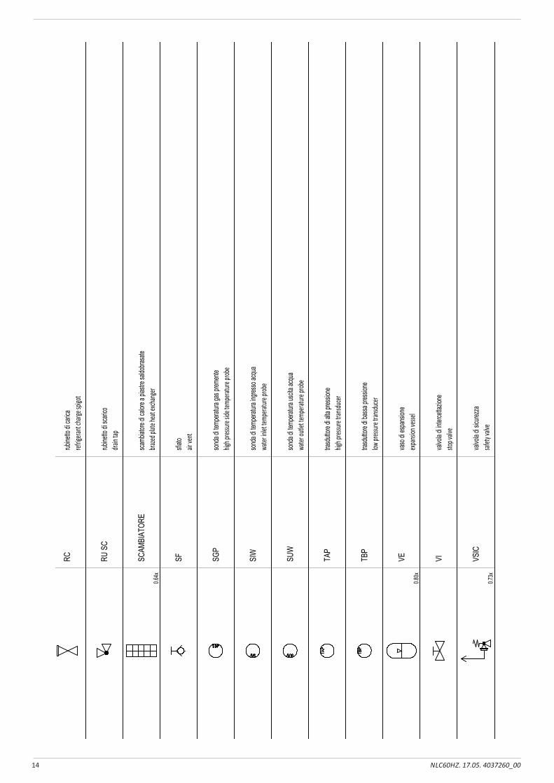
14 NLC60HZ. 17.05. 4037260_00
SYMB
OLS S
UMMA
RY
RIEP
ILOGO
SIMB
OLI S
CHEM
A
NOTE
:
Sym
bol
Sym
bol n
ame
FUN
ZIO
NE
NO
ME
SIM
BO
LOS
IMB
OLO
Note:
Func
tion
rubine
tto di
caric
aref
rigera
nt cha
rge sp
igot
RC
rubine
tto di
scari
codra
in tap
RU S
C
scamb
iatore
di ca
lore a
pias
tre sa
ldobra
sate
brazed
plate
heat
excha
nger
SCAM
BIAT
ORE
0.64x
sfiato
air ve
ntSF
sond
a di te
mpera
tura g
as pr
emen
tehig
h pres
sure s
ide te
mpera
ture p
robe
SGP
sond
a di te
mpera
tura i
ngres
so ac
qua
water
inlet
tempe
rature
prob
eSI
W
sond
a di te
mpera
tura u
scita
acqu
awa
ter ou
tlet te
mpera
ture p
robe
SUW
trasd
uttore
di al
ta pre
ssion
ehig
h pres
sure t
ransdu
cerTA
P
trasd
uttore
di ba
ssa pr
essio
nelow
press
ure tra
nsduce
rTB
P
vaso
di es
pans
ione
expan
sion v
essel
VE
0.80x
valvo
la di
interc
ettaz
ione
stop v
alve
VI
valvo
la di
sicure
zzasaf
ety va
lveVS
IC
0.73x
15NLC60HZ. 17.05. 4037260_00
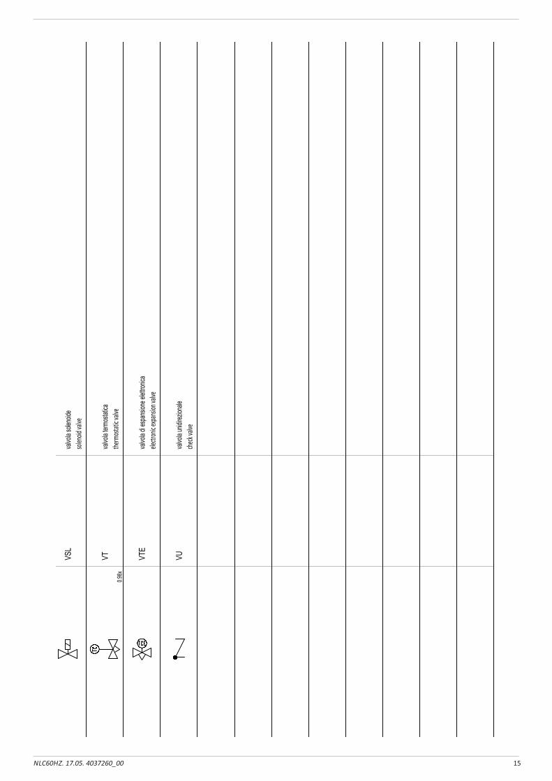
SYMB
OLS S
UMMA
RY
RIEP
ILOGO
SIMB
OLI S
CHEM
A
NOTE
:
Func
tion
Sym
bol n
ame
FUN
ZIO
NE
NO
ME
SIM
BO
LOS
IMB
OLO
Note:
Sym
bol
valvo
la so
lenoid
esol
enoid
valve
VSL
valvo
la ter
mosta
ticathe
rmost
atic v
alve
VT0.9
8x
valvo
la di
espa
nsion
e elet
tronic
aele
ctron
ic expa
nsion
valve
VTE
valvo
la un
idirez
ionale
check
valve
VU
16 NLC60HZ. 17.05. 4037260_00
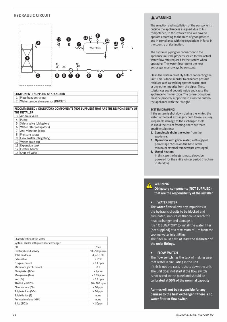
HYDRAULIC CIRCUIT WARNING
The selection and installation of the components outside the appliance is assigned, due to his competence, to the installer who will have to operate according to the rules of good practice and in compliance with the regulations in force in the country of destination. The hydraulic piping for connection to the appliance must be properly scaled for the actual water flow rate required by the system when operating. The water flow rate to the heat exchanger must always be constant. Clean the system carefully before connecting the unit. This is done in order to eliminate possible residues such as welding spatter, waste, rust or any other impurity from the pipes. These substances could deposit inside and cause the appliance to malfunction. The connection pipes must be properly supported so as not to burden the appliance with their weight. SYSTEM DRAININGIf the system is shut down during the winter, the water in the heat exchanger could freeze, causing irreparable damage to the exchanger itself.To avoid the risk of freezing, there are three possible solutions:1. Completely drain the water from the
appliance.2. Operation with glycol water, with a glycol
percentage chosen on the basis of the minimum external temperature envisaged.
3. Use of heaters. In this case the heaters must always be powered for the entire winter period (machine in standby).
COMPONENTS SUPPLIED AS STANDARD1 Plate heat exchanger2 Water temperature sensor (IN/OUT)
RECOMMENDED / OBLIGATORY COMPONENTS (NOT SUPPLIED) THAT ARE THE RESPONSIBILITY OF THE INSTALLER
3 Air drain valve4 Pump5 Safety valve (obligatory)6 Water filter (obligatory)7 Anti-vibration joints8 Pressure gauge9 Flow switch (obligatory)
10 Water drain tap11 Expansion tank12 Electric heater13 Shut-off valve
WARNINGObligatory components (NOT SUPPLIED) that are the responsibility of the installer
• WATER FILTERThe water filter allows any impurities in the hydraulic circuits to be blocked and eliminated; impurities that could reach the heat exchanger and damage it.It is ‘ OBLIGATORY to install the water filter (not supplied) at a maximum of 1 m from the cooling water inlet fitting.The filter must have at least the diameter of the units fittings.
• FLOW SWITCHThe flow switch has the task of making sure that water is circulating in the unit.If this is not the case, it shuts down the unit.The unit does not start if the flow switch is not wired to the panel and should be calibrated at 50% of the nominal capacity
Aermec will not be responsible for any damage to the heat exchanger if there is no water filter or flow switch
Characteristics of the waterSystem: Chiller with plate heat exchangerPH 7.5-9Electrical conductivity 100-500μS/cmTotal hardness 4.5-8.5 dHExternal air < 65°COxygen content < 0.1 ppmMaximum glycol content 0.5Phosphates (PO4) < 2ppmManganese (Mn) < 0.05 ppmIron (Fe) < 0.3 ppmAlkalinity (HCO3) 70 - 300 ppmChlorine ions (Cl-) < 50 ppmSulphate ions (SO4) < 50 ppmSulphide ion (S) noneAmmonium ions (NH4) noneSilica (SiO2) < 30ppm
1
2
2 55 6 7
7
8
8910 1112
13
3
3
4
Water Tank
17NLC60HZ. 17.05. 4037260_00
ACCESSORIES
AER 485P1RS-485 interface for supervising systems with MODBUS protocol.
AERWEB300AERWEB device allows the remote control of a chiller by means of a common PC through Ethernet connection, via a common browser; 4 models available:AERWEB300-6: Web server for monitoring and controlling maximum 6 RS485 network devices;AERWEB300-18: Web server for monitoring and controlling maximum 18 RS485 network devices;AERWEB300-6G: Web server for monitoring and controlling maximum 6 RS485 network devices with integrated GPRS modem;AERWEB300-18G: Web server for monitoring and controlling maximum 18 RS485 network devices with integrated GPRS modem;
PGD1Allows you to control the chiller at a distance.
MULTICHILLER_ULControl, switch-on and switch-off system of the single chillers where multiple units are installed in parallel, always ensuring constant flow rate to the evaporators.
AVXSpring anti-vibration mounts.
VTGroup of anti-vibration supports.
FLGFlanges for ducts.
FL_ULFlow switch.
FILTRO WWater filter.Attention, the flow switch and the water filter must be mounted; failure to do so will void the warranty.
ACCESSORIES MOUNTED IN THE FACTORY:DREPlate peak current reduction electronic device.
RIFNLCCurrent power factor correction. Connected in parallel to the motor, it allows a reduction of the input current (approx. 10%).
KRQAnti-condensate electric board resistance.
CRATESpecial wood cover for transport.
18 NLC60HZ. 17.05. 4037260_00
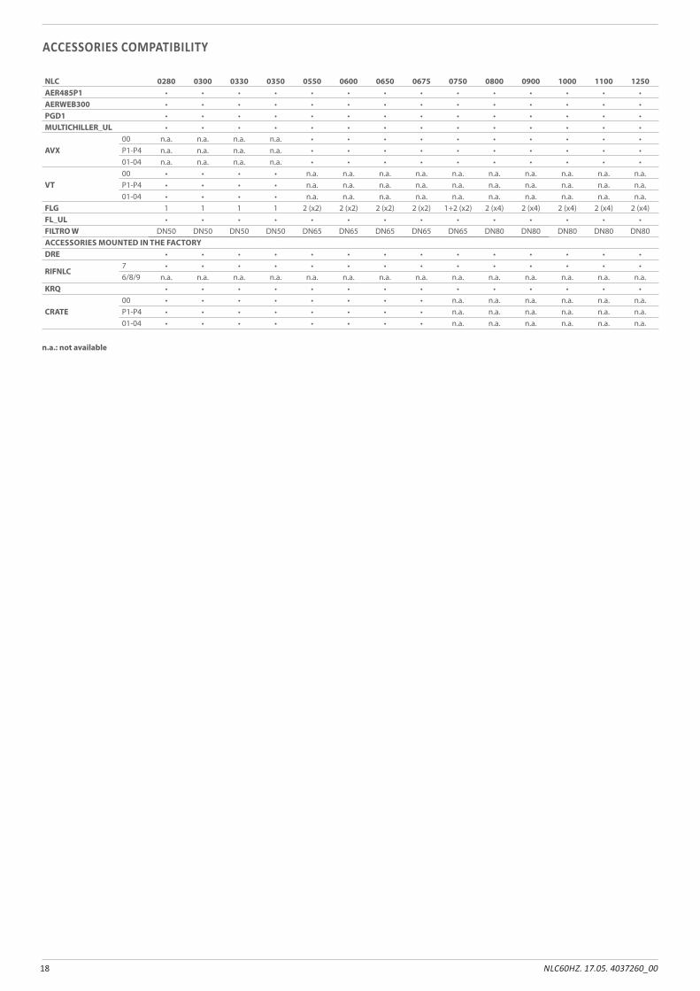
ACCESSORIES COMPATIBILITY
NLC 0280 0300 0330 0350 0550 0600 0650 0675 0750 0800 0900 1000 1100 1250AER485P1 • • • • • • • • • • • • • •AERWEB300 • • • • • • • • • • • • • •PGD1 • • • • • • • • • • • • • •MULTICHILLER_UL • • • • • • • • • • • • • •
AVX00 n.a. n.a. n.a. n.a. • • • • • • • • • •P1-P4 n.a. n.a. n.a. n.a. • • • • • • • • • •01-04 n.a. n.a. n.a. n.a. • • • • • • • • • •
VT00 • • • • n.a. n.a. n.a. n.a. n.a. n.a. n.a. n.a. n.a. n.a.P1-P4 • • • • n.a. n.a. n.a. n.a. n.a. n.a. n.a. n.a. n.a. n.a.01-04 • • • • n.a. n.a. n.a. n.a. n.a. n.a. n.a. n.a. n.a. n.a.
FLG 1 1 1 1 2 (x2) 2 (x2) 2 (x2) 2 (x2) 1+2 (x2) 2 (x4) 2 (x4) 2 (x4) 2 (x4) 2 (x4)FL_UL • • • • • • • • • • • • • •FILTRO W DN50 DN50 DN50 DN50 DN65 DN65 DN65 DN65 DN65 DN80 DN80 DN80 DN80 DN80ACCESSORIES MOUNTED IN THE FACTORYDRE • • • • • • • • • • • • • •
RIFNLC7 • • • • • • • • • • • • • •6/8/9 n.a. n.a. n.a. n.a. n.a. n.a. n.a. n.a. n.a. n.a. n.a. n.a. n.a. n.a.
KRQ • • • • • • • • • • • • • •
CRATE00 • • • • • • • • n.a. n.a. n.a. n.a. n.a. n.a.P1-P4 • • • • • • • • n.a. n.a. n.a. n.a. n.a. n.a.01-04 • • • • • • • • n.a. n.a. n.a. n.a. n.a. n.a.
n.a.: not available
19NLC60HZ. 17.05. 4037260_00
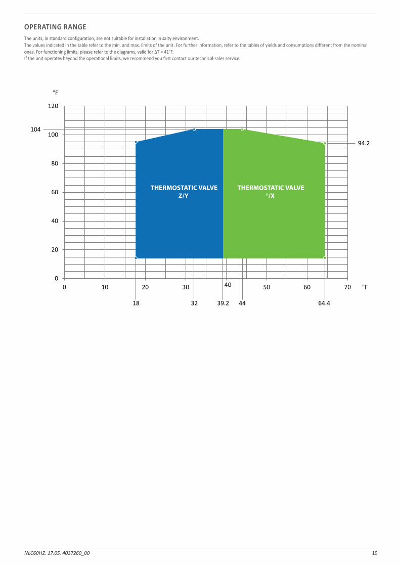
OPERATING RANGEThe units, in standard configuration, are not suitable for installation in salty environment. The values indicated in the table refer to the min. and max. limits of the unit. For further information, refer to the tables of yields and consumptions different from the nominal ones. For functioning limits, please refer to the diagrams, valid for ∆T = 41°F.If the unit operates beyond the operational limits, we recommend you first contact our technical-sales service.
0
20
40
60
80
100104
120
°F
0 10 20
18 32 39.2 44 64.4
94.2
30 40 50 60 70 °F
THERMOSTATIC VALVEZ/Y
THERMOSTATIC VALVE°/X
20 NLC60HZ. 17.05. 4037260_00
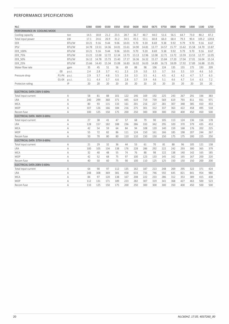
PERFORMANCE SPECIFICATIONS
NLC 0280 0300 0330 0350 0550 0600 0650 0675 0750 0800 0900 1000 1100 1250PERFORMANCE IN COOLING MODECooling capacity ton 14.5 18.8 21.2 23.5 28.7 36.7 40.7 44.0 51.6 56.5 64.7 73.0 80.2 87.2Total input power kW 17.1 24.6 26.9 31.2 34.5 45.5 53.1 60.8 66.0 68.4 79.3 90.4 105.2 120.8EER BTU/W 10.21 9.16 9.44 9.06 10.01 9.70 9.20 8.69 9.38 9.92 9.79 9.70 9.16 8.67IPLV BTU/W 14.78 13.51 14.36 14.01 15.61 14.90 14.81 13.77 14.57 15.77 15.62 15.58 14.70 13.87EER_100% BTU/W 10.21 9.16 9.44 9.06 10.01 9.70 9.20 8.69 9.38 9.92 9.79 9.70 9.16 8.67EER_75% BTU/W 13.21 12.00 12.72 12.34 13.73 13.13 12.96 12.08 12.71 13.72 13.59 13.53 12.77 12.05EER_50% BTU/W 16.12 14.78 15.73 15.40 17.17 16.36 16.32 15.17 15.84 17.20 17.04 17.01 16.04 15.14EER_25% BTU/W 15.66 14.43 15.34 15.08 16.83 16.02 16.03 14.89 16.73 18.09 17.92 17.89 16.88 15.95Water flow rate gpm 35 45 51 56 69 88 98 106 124 135 155 175 193 209
Pressure drop00 p.s.i. 2.4 2.8 3.7 4.1 2.3 2.9 3.0 3.5 3.7 3.6 3.5 3.9 4.6 5.0
P1-P4 p.s.i. 2.9 3.7 4.8 5.5 2.6 3.3 3.5 4.1 4.5 4.2 4.2 4.7 5.7 6.301-04 p.s.i. 3.1 4.4 5.7 6.6 2.8 3.7 3.9 4.6 5.1 4.6 4.7 5.4 6.5 7.2
Protecion rating IP 20 20 20 20 20 20 20 20 20 20 20 20 20 20
ELECTRICAL DATA 230V-3-60HzTotal input current A 58 81 88 101 122 146 169 192 225 243 267 291 336 383LRA A 240 299 360 371 445 619 719 739 569 619 793 811 931 971MCA A 80 93 115 133 161 201 216 227 281 307 348 385 410 433MOP A 107 126 166 184 216 275 301 312 337 363 422 458 495 518Recom fuse A 100 125 150 175 200 250 300 300 300 350 400 450 450 500ELECTRICAL DATA 460V-3-60HzTotal input current A 27 38 41 47 57 68 79 90 105 113 124 136 156 178LRA A 128 157 182 188 236 286 333 342 295 320 370 379 435 453MCA A 42 54 59 64 84 94 108 120 140 159 168 176 202 225MOP A 55 72 82 86 111 124 150 161 166 185 198 207 244 267Recom fuse A 50 70 80 80 110 110 150 150 150 175 175 200 225 250ELECTRICAL DATA 575V-3-60HzTotal input current A 21 29 32 36 44 53 61 70 81 88 96 105 121 138LRA A 100 105 134 138 176 228 286 292 222 242 293 300 365 379MCA A 32 40 48 55 74 76 88 98 122 138 140 142 165 185MOP A 42 52 68 75 97 100 123 133 145 162 165 167 200 220Recom fuse A 40 50 60 75 90 100 110 125 125 150 150 150 200 200ELECTRICAL DATA 208V-3-60HzTotal input current A 64 90 97 112 135 162 187 213 248 269 295 322 371 424LRA A 248 308 369 381 458 633 733 746 592 645 821 841 954 980MCA A 84 97 120 138 167 208 222 233 286 312 353 389 415 438MOP A 112 131 171 189 223 282 307 319 341 368 427 463 500 523Recom fuse A 110 125 150 175 200 250 300 300 300 350 400 450 500 500
21NLC60HZ. 17.05. 4037260_00
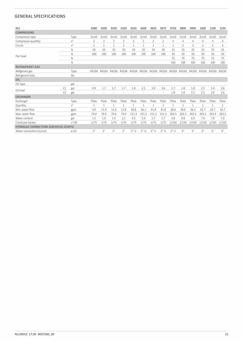
NLC 0280 0300 0330 0350 0550 0600 0650 0675 0750 0800 0900 1000 1100 1250COMPRESSORSCompressor type Type Scroll Scroll Scroll Scroll Scroll Scroll Scroll Scroll Scroll Scroll Scroll Scroll Scroll ScrollCompressor quantity n° 2 2 2 2 2 2 2 2 4 4 4 4 4 4Circuit n° 1 1 1 1 1 1 1 1 2 2 2 2 2 2
Part load
% 50 50 50 50 50 50 50 50 25 25 25 25 25 25% 100 100 100 100 100 100 100 100 50 50 50 50 50 50% 75 75 75 75 75 75% 100 100 100 100 100 100
REFRIGERANT GASRefigerant gas Type R410A R410A R410A R410A R410A R410A R410A R410A R410A R410A R410A R410A R410A R410ARefrigerant load lbsOILOil Type gal
Oil loadC1 gal 0.9 1.7 1.7 1.7 1.8 2.5 3.0 3.6 1.7 1.8 1.8 2.5 3.0 3.6C2 gal - - - - - - - - 1.8 1.8 2.5 2.5 3.0 3.6
EXCHANGERExchanger Type Plate Plate Plate Plate Plate Plate Plate Plate Plate Plate Plate Plate Plate PlateQuantity n° 1 1 1 1 1 1 1 1 1 1 1 1 1 1Min. water flow gpm 9.0 11.9 11.9 12.8 30.8 36.1 41.8 41.8 28.6 28.6 36.5 42.7 42.7 42.7Max. water flow gpm 74.0 74.0 74.0 74.0 211.3 211.3 211.3 211.3 263.3 263.3 263.3 263.3 263.3 263.3Water content gal 1.5 1.9 1.9 2.1 4.2 5.0 5.7 5.7 4.8 4.8 6.0 7.0 7.0 7.0Crankcase heater n°/W 1/75 1/75 1/75 1/75 1/75 1/75 1/75 1/75 1/150 1/150 1/150 1/150 1/150 1/150HYDRAULIC CONNECTIONS (GROOVED JOINTS)Water connection (in/out) ø US 2" 2" 2" 2" 2" 1/2 2” 1/2 2” 1/2 2” 1/2 2” 1/2 3" 3" 3" 3" 3"
GENERAL SPECIFICATIONS
22 NLC60HZ. 17.05. 4037260_00
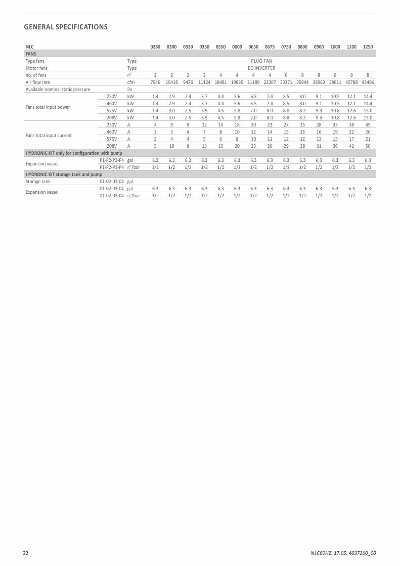
NLC 0280 0300 0330 0350 0550 0600 0650 0675 0750 0800 0900 1000 1100 1250FANSType fans Type PLUG-FANMotor fans Type EC-INVERTERno. of fans n° 2 2 2 2 4 4 4 4 6 8 8 8 8 8Air flow rate cfm 7946 10418 9476 11124 18481 19835 21189 22307 30371 35844 36963 38611 40788 43496Available nominal static pressure Pa
Fans total input power
230V kW 1.4 2.9 2.4 3.7 4.4 5.6 6.5 7.4 8.5 8.0 9.1 10.5 12.1 14.4460V kW 1.4 2.9 2.4 3.7 4.4 5.6 6.5 7.4 8.5 8.0 9.1 10.5 12.1 14.4575V kW 1.4 3.0 2.5 3.9 4.5 5.8 7.0 8.0 8.8 8.2 9.3 10.8 12.6 15.0208V kW 1.4 3.0 2.5 3.9 4.5 5.8 7.0 8.0 8.8 8.2 9.3 10.8 12.6 15.0
Fans total input current
230V A 4 9 8 12 14 18 20 23 27 25 28 33 38 45460V A 3 5 4 7 8 10 12 14 15 15 16 19 22 26575V A 2 4 4 5 6 8 10 11 12 12 13 15 17 21208V A 5 10 8 13 15 20 23 26 29 28 31 36 42 50
HYDRONIC KIT only for configuration with pump
Expansion vasselP1-P2-P3-P4 gal 6.3 6.3 6.3 6.3 6.3 6.3 6.3 6.3 6.3 6.3 6.3 6.3 6.3 6.3P1-P2-P3-P4 n°/bar 1/2 1/2 1/2 1/2 1/2 1/2 1/2 1/2 1/2 1/2 1/2 1/2 1/2 1/2
HYDRONIC KIT storage tank and pump Storage tank 01-02-03-04 gal
Expansion vassel01-02-03-04 gal 6.3 6.3 6.3 6.3 6.3 6.3 6.3 6.3 6.3 6.3 6.3 6.3 6.3 6.301-02-03-04 n°/bar 1/2 1/2 1/2 1/2 1/2 1/2 1/2 1/2 1/2 1/2 1/2 1/2 1/2 1/2
GENERAL SPECIFICATIONS
23NLC60HZ. 17.05. 4037260_00
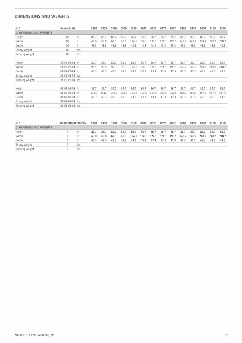
NLC Hydronic kit 0280 0300 0330 0350 0550 0600 0650 0675 0750 0800 0900 1000 1100 1250DIMENSIONS AND WEIGHTSHeight 00 in 86.7 86.7 86.7 86.7 86.7 86.7 86.7 86.7 86.7 86.7 86.7 86.7 86.7 86.7Width 00 in 69.0 69.0 69.0 69.0 124.1 124.1 124.1 124.1 193.1 248.2 248.2 248.2 248.2 248.2Depth 00 in 43.3 43.3 43.3 43.3 43.3 43.3 43.3 43.3 43.3 43.3 43.3 43.3 43.3 43.3Empty weight 00 lbsRunning weight 00 lbs
Height P1-P2-P3-P4 in 86.7 86.7 86.7 86.7 86.7 86.7 86.7 86.7 86.7 86.7 86.7 86.7 86.7 86.7Width P1-P2-P3-P4 in 98.5 98.5 98.5 98.5 124.1 124.1 124.1 124.1 193.1 248.2 248.2 248.2 248.2 248.2Depth P1-P2-P3-P4 in 43.3 43.3 43.3 43.3 43.3 43.3 43.3 43.3 43.3 43.3 43.3 43.3 43.3 43.3Empty weight P1-P2-P3-P4 lbsRunning weight P1-P2-P3-P4 lbs
Height 01-02-03-04 in 86.7 86.7 86.7 86.7 86.7 86.7 86.7 86.7 86.7 86.7 86.7 86.7 86.7 86.7Width 01-02-03-04 in 134.0 134.0 134.0 134.0 163.5 163.5 163.5 163.5 232.5 287.6 287.6 287.6 287.6 287.6Depth 01-02-03-04 in 43.3 43.3 43.3 43.3 43.3 43.3 43.3 43.3 43.3 43.3 43.3 43.3 43.3 43.3Empty weight 01-02-03-04 lbsRunning weight 01-02-03-04 lbs
NLC HEATHING RECOVERY 0280 0300 0330 0350 0550 0600 0650 0675 0750 0800 0900 1000 1100 1250DIMENSIONS AND WEIGHTSHeight T in 86.7 86.7 86.7 86.7 86.7 86.7 86.7 86.7 86.7 86.7 86.7 86.7 86.7 86.7Width T in 69.0 69.0 69.0 69.0 124.1 124.1 124.1 124.1 193.1 248.2 248.2 248.2 248.2 248.2Depth T in 43.3 43.3 43.3 43.3 43.3 43.3 43.3 43.3 43.3 43.3 43.3 43.3 43.3 43.3Empty weight T lbsRunning weight T lbs
DIMENSIONS AND WEIGHTS
24 NLC60HZ. 17.05. 4037260_00
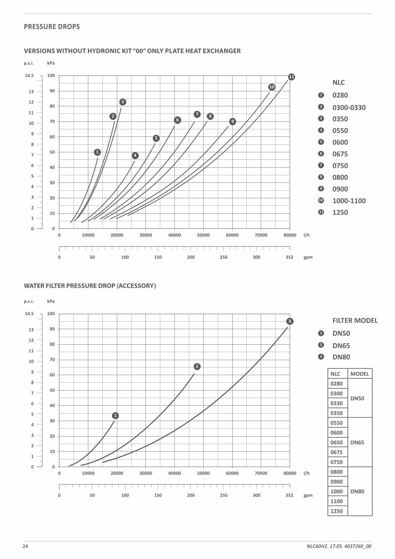
WATER FILTER PRESSURE DROP (ACCESSORY)
VERSIONS WITHOUT HYDRONIC KIT “00” ONLY PLATE HEAT EXCHANGER
PRESSURE DROPS
0
10
20
30
40
50
60
70
80
90
10014.5
kPa
0
1
2
3
4
5
6
7
8
9
10
11
12
13
p.s.i.
0
0 50 100 150 200 250 300 352 gpm
10000 20000 30000 40000 50000 60000 70000 80000 l/h
2
3
1 0280
NLC
0300-03300350
4 05505 06006 06757 07508 08009 0900
10 1000-110011 1250
1
2
3
4
5
67 8
9
10
11
0
10
20
30
40
50
60
70
80
90
10014.5
kPa
0
1
2
3
4
5
6
7
8
9
10
11
12
13
p.s.i.
0
0 50 100 150 200 250 300 352 gpm
10000 20000 30000 40000 50000 60000 70000 80000 l/h
2
3
1 DN50
FILTER MODEL
DN65DN80
1
2
3
NLC MODEL
0280
DN500300
0330
0350
0550
DN65
0600
0650
0675
0750
0800
DN80
0900
1000
1100
1250
25NLC60HZ. 17.05. 4037260_00
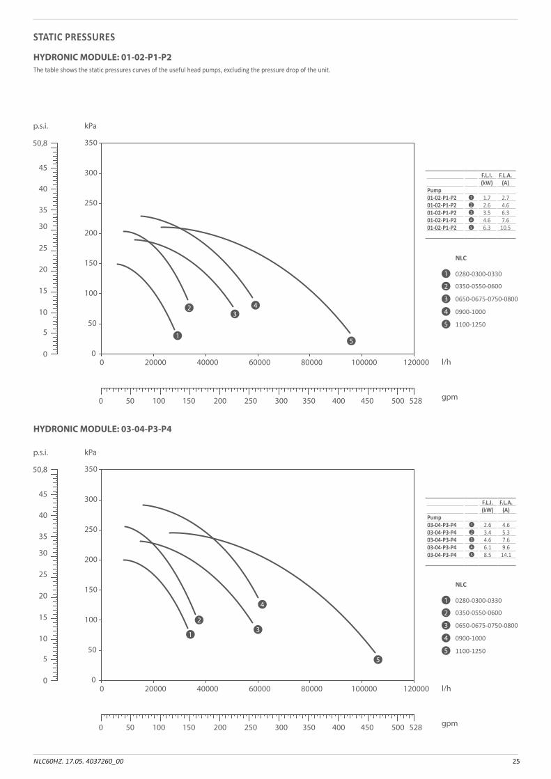
STATIC PRESSURES
HYDRONIC MODULE: 03-04-P3-P4
The table shows the static pressures curves of the useful head pumps, excluding the pressure drop of the unit.
HYDRONIC MODULE: 01-02-P1-P2
0
50
100
150
200
250
300
350
0 20000 40000 60000 80000 100000 120000 l/h
0280-0300-0330
NLC
0350-0550-0600
0650-0675-0750-0800
0900-1000
1100-1250
p.s.i. kPa
5
10
15
20
25
30
35
40
45
50,8
0
0 50 100 150 200 250 300 350 400 450 528500 gpm
1
2
3
4
5
1
23
4
5
F.L.I. F.L.A.(kW) (A)
Pump01-02-P1-P2 1 1.7 2.701-02-P1-P2 2 2.6 4.601-02-P1-P2 3 3.5 6.301-02-P1-P2 4 4.6 7.601-02-P1-P2 5 6.3 10.5
0
50
100
150
200
250
300
350
0 20000 40000 60000 80000 100000 120000 l/h
0280-0300-0330
NLC
0350-0550-0600
0650-0675-0750-0800
0900-1000
1100-1250
p.s.i. kPa
5
10
15
20
25
30
35
40
45
50,8
0
0 50 100 150 200 250 300 350 400 450 528500 gpm
1
2
3
4
5
2
13
4
5
F.L.I. F.L.A.(kW) (A)
Pump03-04-P3-P4 1 2.6 4.603-04-P3-P4 2 3.4 5.303-04-P3-P4 3 4.6 7.603-04-P3-P4 4 6.1 9.603-04-P3-P4 5 8.5 14.1
26 NLC60HZ. 17.05. 4037260_00
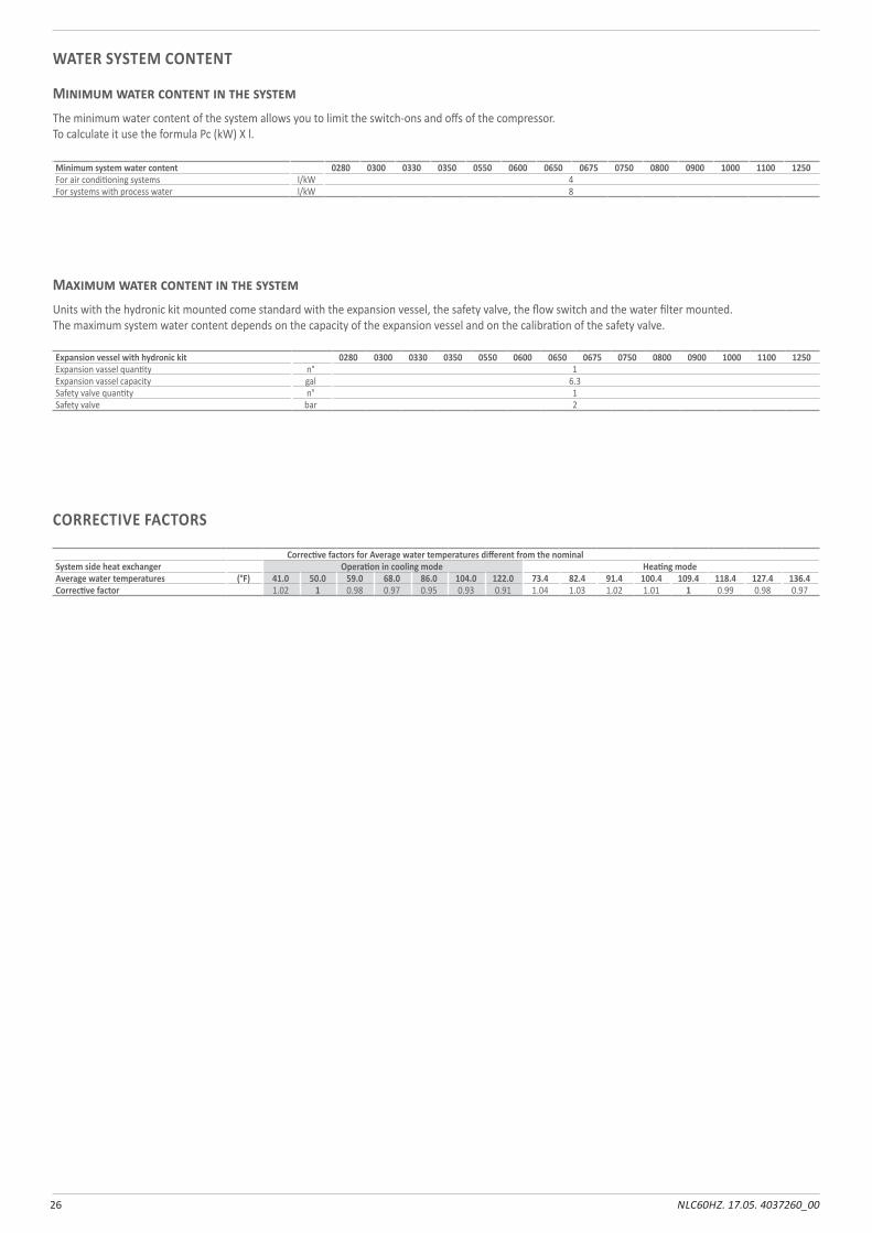
WATER SYSTEM CONTENT
CORRECTIVE FACTORS
Minimum water content in the systemThe minimum water content of the system allows you to limit the switch-ons and offs of the compressor.To calculate it use the formula Pc (kW) X l.
Maximum water content in the systemUnits with the hydronic kit mounted come standard with the expansion vessel, the safety valve, the flow switch and the water filter mounted.The maximum system water content depends on the capacity of the expansion vessel and on the calibration of the safety valve.
Minimum system water content 0280 0300 0330 0350 0550 0600 0650 0675 0750 0800 0900 1000 1100 1250For air conditioning systems l/kW 4For systems with process water l/kW 8
Expansion vessel with hydronic kit 0280 0300 0330 0350 0550 0600 0650 0675 0750 0800 0900 1000 1100 1250Expansion vassel quantity n° 1Expansion vassel capacity gal 6.3Safety valve quantity n° 1Safety valve bar 2
Corrective factors for Average water temperatures different from the nominalSystem side heat exchanger Operation in cooling mode Heating modeAverage water temperatures (°F) 41.0 50.0 59.0 68.0 86.0 104.0 122.0 73.4 82.4 91.4 100.4 109.4 118.4 127.4 136.4Corrective factor 1.02 1 0.98 0.97 0.95 0.93 0.91 1.04 1.03 1.02 1.01 1 0.99 0.98 0.97
27NLC60HZ. 17.05. 4037260_00
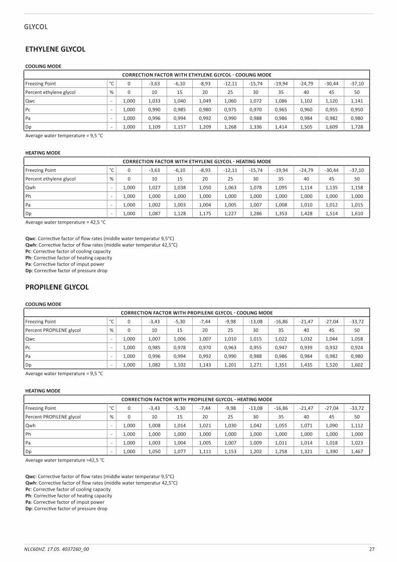
GLYCOL
ETHYLENE GLYCOL
COOLING MODE
CORRECTION FACTOR WITH ETHYLENE GLYCOL - COOLING MODE
Freezing Point °C 0 -3,63 -6,10 -8,93 -12,11 -15,74 -19,94 -24,79 -30,44 -37,10
Percent ethylene glycol % 0 10 15 20 25 30 35 40 45 50
Qwc - 1,000 1,033 1,040 1,049 1,060 1,072 1,086 1,102 1,120 1,141
Pc - 1,000 0,990 0,985 0,980 0,975 0,970 0,965 0,960 0,955 0,950
Pa - 1,000 0,996 0,994 0,992 0,990 0,988 0,986 0,984 0,982 0,980
Dp - 1,000 1,109 1,157 1,209 1,268 1,336 1,414 1,505 1,609 1,728
Average water temperature = 9,5 °C
HEATING MODE
CORRECTION FACTOR WITH ETHYLENE GLYCOL - HEATING MODE
Freezing Point °C 0 -3,63 -6,10 -8,93 -12,11 -15,74 -19,94 -24,79 -30,44 -37,10
Percent ethylene glycol % 0 10 15 20 25 30 35 40 45 50
Qwh - 1,000 1,027 1,038 1,050 1,063 1,078 1,095 1,114 1,135 1,158
Ph - 1,000 1,000 1,000 1,000 1,000 1,000 1,000 1,000 1,000 1,000
Pa - 1,000 1,002 1,003 1,004 1,005 1,007 1,008 1,010 1,012 1,015
Dp - 1,000 1,087 1,128 1,175 1,227 1,286 1,353 1,428 1,514 1,610
Average water temperature = 42,5 °C
Qwc: Correcti ve factor of fl ow rates (middle water temperatur 9,5°C)Qwh: Correcti ve factor of fl ow rates (middle water temperatur 42,5°C)Pc: Correcti ve factor of cooling capacityPh: Correcti ve factor of heati ng capacityPa: Correcti ve factor of imput powerDp: Correcti ve factor of pressure drop
PROPILENE GLYCOL
COOLING MODE
CORRECTION FACTOR WITH PROPILENE GLYCOL - COOLING MODE
Freezing Point °C 0 -3,43 -5,30 -7,44 -9,98 -13,08 -16,86 -21,47 -27,04 -33,72
Percent PROPILENE glycol % 0 10 15 20 25 30 35 40 45 50
Qwc - 1,000 1,007 1,006 1,007 1,010 1,015 1,022 1,032 1,044 1,058
Pc - 1,000 0,985 0,978 0,970 0,963 0,955 0,947 0,939 0,932 0,924
Pa - 1,000 0,996 0,994 0,992 0,990 0,988 0,986 0,984 0,982 0,980
Dp - 1,000 1,082 1,102 1,143 1,201 1,271 1,351 1,435 1,520 1,602
Average water temperature = 9,5 °C
HEATING MODE
CORRECTION FACTOR WITH PROPILENE GLYCOL - HEATING MODE
Freezing Point °C 0 -3,43 -5,30 -7,44 -9,98 -13,08 -16,86 -21,47 -27,04 -33,72
Percent PROPILENE glycol % 0 10 15 20 25 30 35 40 45 50
Qwh - 1,000 1,008 1,014 1,021 1,030 1,042 1,055 1,071 1,090 1,112
Ph - 1,000 1,000 1,000 1,000 1,000 1,000 1,000 1,000 1,000 1,000
Pa - 1,000 1,003 1,004 1,005 1,007 1,009 1,011 1,014 1,018 1,023
Dp - 1,000 1,050 1,077 1,111 1,153 1,202 1,258 1,321 1,390 1,467
Average water temperature =42,5 °C
Qwc: Correcti ve factor of fl ow rates (middle water temperatur 9,5°C)Qwh: Correcti ve factor of fl ow rates (middle water temperatur 42,5°C)Pc: Correcti ve factor of cooling capacityPh: Correcti ve factor of heati ng capacityPa: Correcti ve factor of imput powerDp: Correcti ve factor of pressure drop
28 NLC60HZ. 17.05. 4037260_00
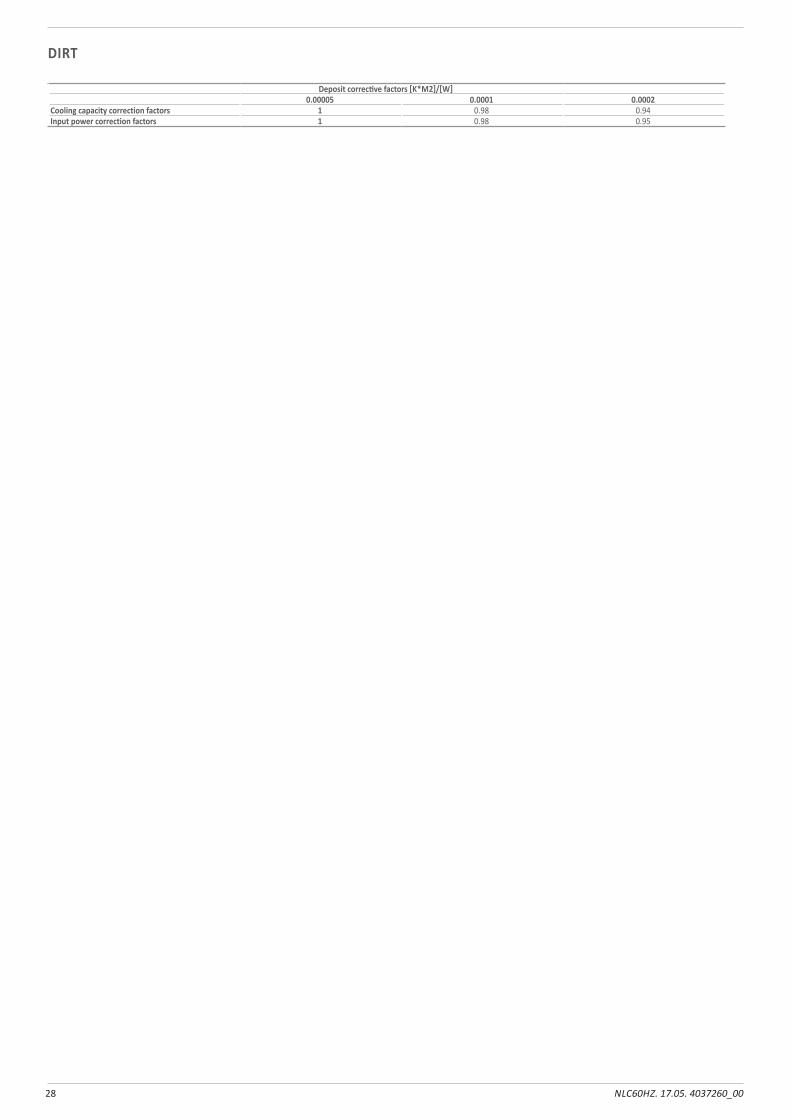
Deposit corrective factors [K*M2]/[W]0.00005 0.0001 0.0002
Cooling capacity correction factors 1 0.98 0.94Input power correction factors 1 0.98 0.95
DIRT
29NLC60HZ. 17.05. 4037260_00
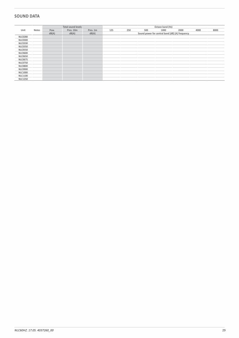
SOUND DATA
Unit NotesTotal sound levels Octave band (Hz)
Pow. Pres. 10m Pres. 1m 125 250 500 1000 2000 4000 8000dB(A) dB(A) dB(A) Sound power for central band [dB] (A) frequency
NLC0280NLC0300NLC0330NLC0350NLC0550NLC0600NLC0650NLC0675NLC0750NLC0800NLC0900NLC1000NLC1100NLC1250
30 NLC60HZ. 17.05. 4037260_00
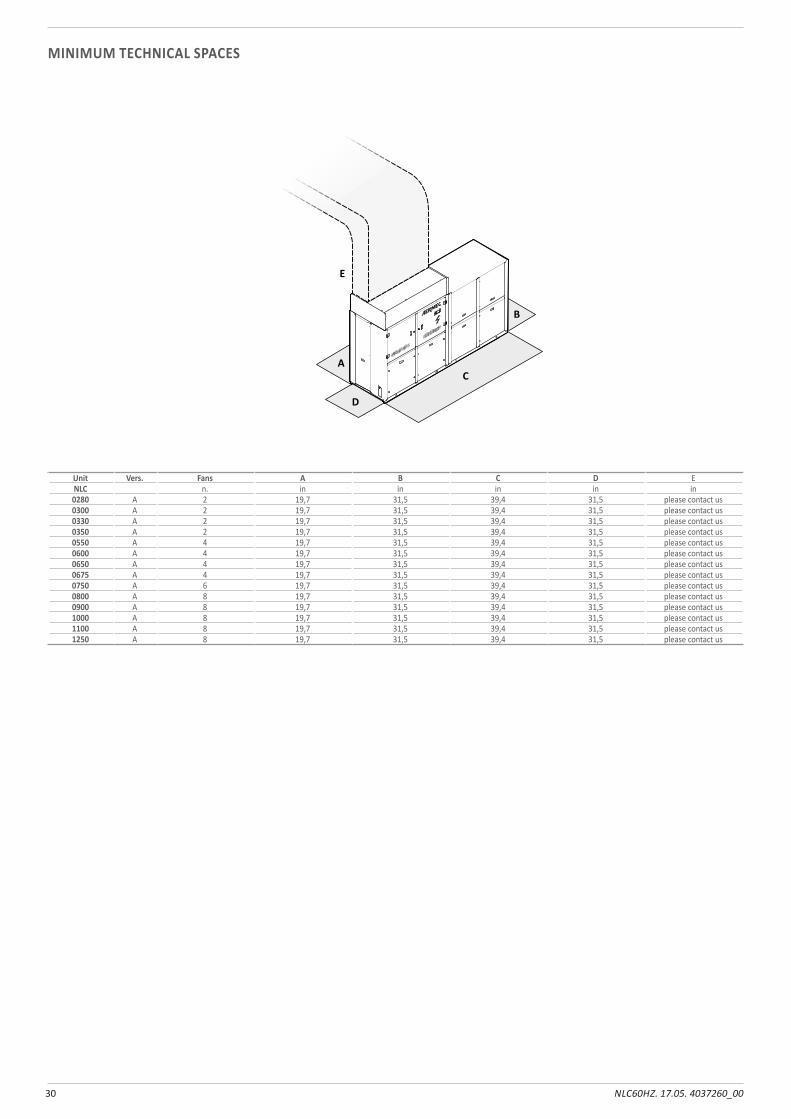
MINIMUM TECHNICAL SPACES
A
B
E
C
D
Unit Vers. Fans A B C D ENLC n. in in in in in0280 A 2 19,7 31,5 39,4 31,5 please contact us0300 A 2 19,7 31,5 39,4 31,5 please contact us0330 A 2 19,7 31,5 39,4 31,5 please contact us0350 A 2 19,7 31,5 39,4 31,5 please contact us0550 A 4 19,7 31,5 39,4 31,5 please contact us0600 A 4 19,7 31,5 39,4 31,5 please contact us0650 A 4 19,7 31,5 39,4 31,5 please contact us0675 A 4 19,7 31,5 39,4 31,5 please contact us0750 A 6 19,7 31,5 39,4 31,5 please contact us0800 A 8 19,7 31,5 39,4 31,5 please contact us0900 A 8 19,7 31,5 39,4 31,5 please contact us1000 A 8 19,7 31,5 39,4 31,5 please contact us1100 A 8 19,7 31,5 39,4 31,5 please contact us1250 A 8 19,7 31,5 39,4 31,5 please contact us
31NLC60HZ. 17.05. 4037260_00
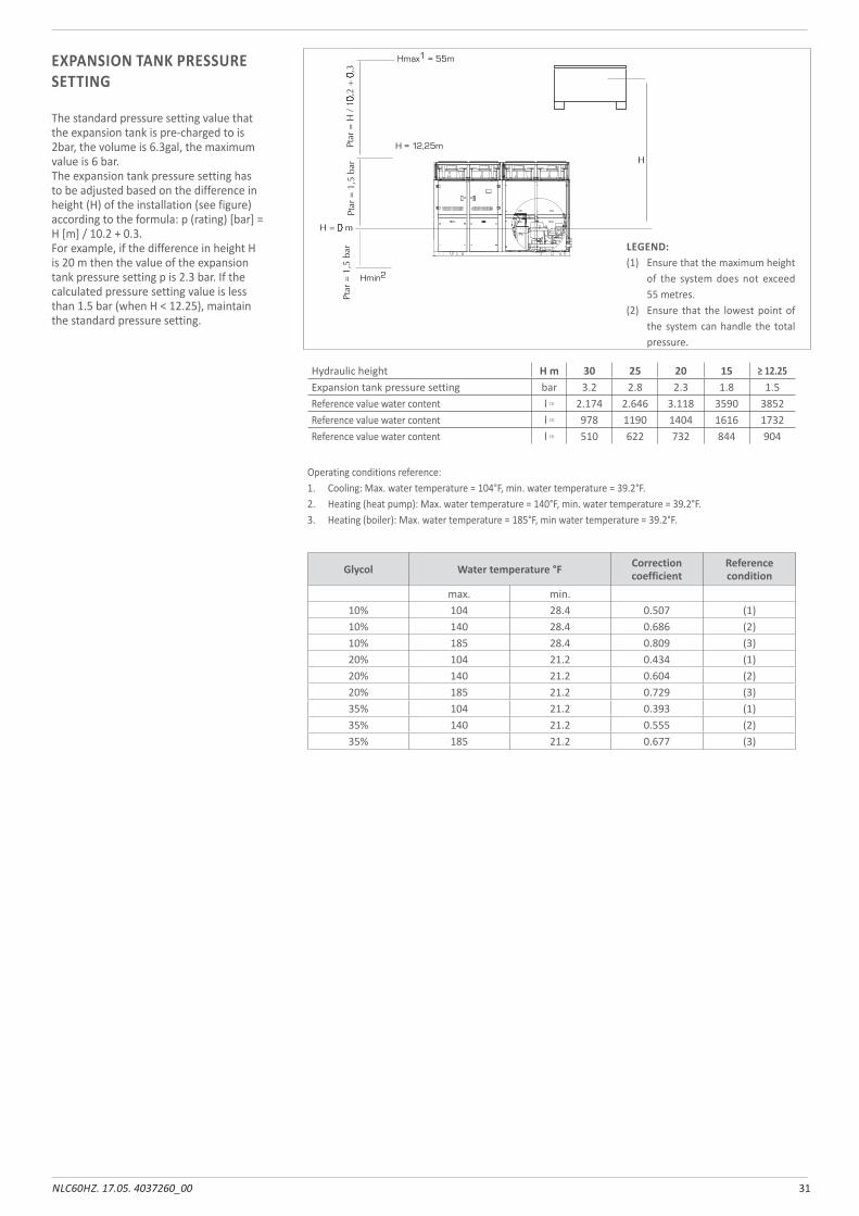
Hydraulic height H m 30 25 20 15 ≥ 12.25Expansion tank pressure setting bar 3.2 2.8 2.3 1.8 1.5Reference value water content l (1) 2.174 2.646 3.118 3590 3852Reference value water content l (2) 978 1190 1404 1616 1732Reference value water content l (3) 510 622 732 844 904
Operating conditions reference:1. Cooling: Max. water temperature = 104°F, min. water temperature = 39.2°F.2. Heating (heat pump): Max. water temperature = 140°F, min. water temperature = 39.2°F.3. Heating (boiler): Max. water temperature = 185°F, min water temperature = 39.2°F.
LEGEND:(1) Ensure that the maximum height
of the system does not exceed 55 metres.
(2) Ensure that the lowest point of the system can handle the total pressure.
Glycol Water temperature °F Correction coefficient
Reference condition
max. min.10% 104 28.4 0.507 (1)10% 140 28.4 0.686 (2)10% 185 28.4 0.809 (3)20% 104 21.2 0.434 (1)20% 140 21.2 0.604 (2)20% 185 21.2 0.729 (3)35% 104 21.2 0.393 (1)35% 140 21.2 0.555 (2)35% 185 21.2 0.677 (3)
EXPANSION TANK PRESSURE SETTING
The standard pressure setting value that the expansion tank is pre-charged to is 2bar, the volume is 6.3gal, the maximum value is 6 bar. The expansion tank pressure setting has to be adjusted based on the difference in height (H) of the installation (see figure) according to the formula: p (rating) [bar] = H [m] / 10.2 + 0.3.For example, if the difference in height H is 20 m then the value of the expansion tank pressure setting p is 2.3 bar. If the calculated pressure setting value is less than 1.5 bar (when H < 12.25), maintain the standard pressure setting.


carta riciclatarecycled paperpapier recyclérecycled Papier
AERMEC S.p.A.Via Roma, 99637040 Bevilacqua (VR) - ItalyTel. + 39 0442 633111Fax +39 0442 93577www.aermec.com
Aermec reserves the right to make all modification deemed necessary for improving the product at any time with any modification of technical data.