Embed Size (px)
Citation preview

ID 181/337: Version 1, February 6, 2015
en USER GUIDE ekey net 4.3

en|2
English Translation of the original instructions – ID181/337/0/251
Table of contents
1 General ....................................................................................................................... 5
1.1 Note ...................................................................................................................... 5 1.2 Product liability and limitation of liability ..................................................................... 5 1.3 Warranty and manufacturer's warranty ...................................................................... 5
2 Notices, symbols, and abbreviations ........................................................................... 5 3 Safety information ...................................................................................................... 6 4 Product description ..................................................................................................... 7
4.1 System overview ..................................................................................................... 7 4.2 Scope of delivery and system requirements ................................................................ 7 4.3 Proper use and areas of application ............................................................................ 7 4.4 ekey bit and ekey net finger scanners ........................................................................ 8
4.4.1 Function of the finger scanner ............................................................................. 8 4.4.2 Control for the ekey bit/ekey net finger scanner .................................................... 8 4.4.3 Correct operation of the finger scanner: ............................................................... 9
4.5 Control panel .......................................................................................................... 9
4.5.1 Function of the control panel ............................................................................... 9 4.5.2 Controls and optical signals of the control panel .................................................. 10
5 Technical specifications ............................................................................................ 10 6 Hardware installation ............................................................................................... 10 7 Commissioning of the finger scanners and control panels ........................................ 10 8 Software installation................................................................................................. 11
8.1 Preparatory steps .................................................................................................. 11 8.2 General installation procedure ................................................................................. 11 8.3 Initial installation ................................................................................................... 12 8.4 Updating older versions .......................................................................................... 15
8.4.1 Updating ekey TOCAnet .................................................................................... 15 8.4.2 Updating an older version of ekey net ................................................................ 16
8.5 Important tasks to be performed after installation or an update .................................. 16 8.6 Uninstalling the software ........................................................................................ 17
9 Configuration ............................................................................................................ 17
9.1 Managing licenses .................................................................................................. 18
9.1.1 Entering user data ........................................................................................... 19 9.1.2 Adding a license .............................................................................................. 19 9.1.3 Activating a license .......................................................................................... 20 9.1.4 Upgrading your license to ekey net business ....................................................... 20
9.2 Starting and stopping ekey net services ................................................................... 20 9.3 Configuring the ekey net converter LAN and updating the firmware ............................. 21
9.3.1 Using the MAC address to define the IP address .................................................. 22 9.3.2 Defining the IP address by selecting it from the list .............................................. 23 9.3.3 Updating the firmware...................................................................................... 23 9.3.4 Checking the function of ekey net converter LANs on the network ........................ 23 9.3.5 ekey net converter LAN not found ...................................................................... 24
9.4 Updating the firmware of the finger scanner, control panel, and ekey net converter
Wiegand devices ............................................................................................................ 25
10 Administration of ekey net ........................................................................................ 26
10.1 Login dialog .......................................................................................................... 26

en│3
10.2 Global menu ......................................................................................................... 27 10.3 START menu ......................................................................................................... 28 10.4 DATA menu........................................................................................................... 29 10.5 USER menu........................................................................................................... 30
10.5.1 Creating/editing users ...................................................................................... 30
10.6 TERMINALS menu .................................................................................................. 35
10.6.1 ekey net terminal server................................................................................... 36 10.6.2 Terminal group ................................................................................................ 38 10.6.3 ekey net converter LAN .................................................................................... 38 10.6.4 Control panel .................................................................................................. 41 10.6.5 Finger scanner ................................................................................................ 44 10.6.6 RFID reader .................................................................................................... 49 10.6.7 Calendar......................................................................................................... 52 10.6.8 Time zone....................................................................................................... 52
10.7 AUTHORIZATIONS menu ........................................................................................ 55 10.8 STATUS menu ....................................................................................................... 56 10.9 BASIC SETTINGS menu .......................................................................................... 58
10.9.1 BASIC SETTINGS – OPTIONS ............................................................................ 58 10.9.2 BASIC SETTINGS – ACTIONS ............................................................................ 59 10.9.3 BASIC SETTINGS – EVENTS .............................................................................. 62 10.9.4 BASIC SETTINGS – DEVICES ............................................................................ 64 10.9.5 BASIC SETTINGS – RIGHTS .............................................................................. 66 10.9.6 BASIC SETTINGS – USER DATA ......................................................................... 68 10.9.7 BASIC SETTINGS: LOGGING ............................................................................. 68
10.10 The wizard ............................................................................................................ 73 10.11 Log display ........................................................................................................... 75
11 Extended functions ................................................................................................... 75
11.1 Installing MS SQL Server 2008 R2 Express................................................................ 75 11.2 Logging operations ................................................................................................ 76
11.2.1 Configuring ODBC logging operations ................................................................. 76 11.2.2 Configuring web logging operations ................................................................... 77
11.3 Reporting ............................................................................................................. 77
11.3.1 Configuring the OBDC connection to SQL Server .................................................. 78 11.3.2 Configuring reporting in ekey net admin ............................................................. 80 11.3.3 Finger scanner report and User report ................................................................ 80
11.4 Consistency check ................................................................................................. 81 11.5 FAR problem report ................................................................................................ 82 11.6 Attendance list ...................................................................................................... 83
11.6.1 Defining an exit event and action ...................................................................... 83 11.6.2 Recording attendance with two different reference finger scans per user ................ 84 11.6.3 Recording attendance with one reference finger scan per user .............................. 84 11.6.4 Working with the attendance list ....................................................................... 84
11.7 Concierge mode .................................................................................................... 85 11.8 Accessing an ekey net terminal server via the Web .................................................... 86
11.8.1 Logging in with a single-use PIN ........................................................................ 86 11.8.2 Logging in with a user ID and password ............................................................. 87
11.9 Power-on reset special configuration ........................................................................ 88 11.10 Composite control panel ......................................................................................... 89 11.11 Automatic time-controlled operation for a control panel .............................................. 89 11.12 Action boundaries .................................................................................................. 90
11.12.1 Defining action boundaries ................................................................................ 90 11.12.2 Creating a customized action with zone switching ................................................ 90 11.12.3 Creating a customized event with zone switching ................................................. 90 11.12.4 Assigning a customized event to reference finger scans ........................................ 91
11.13 Keep-switched function .......................................................................................... 91 11.14 UDP transmission .................................................................................................. 91

en│4
11.14.1 Protocol formats for UDP transmission ................................................................ 92 11.14.2 UDP transmission by the ekey net terminal server ............................................... 94 11.14.3 UDP transmission by the ekey net converter LAN ................................................. 95
11.15 Wiegand ............................................................................................................... 95 11.16 ekey net SDK ........................................................................................................ 97
12 Details concerning INI files ...................................................................................... 97
12.1 INI entries for ekey net admin ................................................................................. 97 12.2 INI entries for ekey net master server ...................................................................... 98 12.3 INI entries for ekey net terminal server .................................................................... 99
13 Hardware maintenance ............................................................................................. 99 14 Dismantling and disposal .......................................................................................... 99 15 Declaration of conformity ....................................................................................... 100 16 Copyright ................................................................................................................ 100
en│5
1 General
ekey biometric systems GmbH operates a quality management system in compliance with EN ISO
9001:2008 and is certified accordingly.
1.1 Note
These instructions form a component of the product. Ensure that they are stored in a safe place.
Please contact your dealer for further information about the product.
1.2 Product liability and limitation of liability
Safe operation and function of the devices can be impaired in the following situations. Liability due
to malfunctioning is transferred to the operator/user in such cases:
□ The system devices are not installed, used, maintained, and cleaned in accordance with the
instructions
□ The system devices are not used within the scope of proper use
□ Unauthorized modifications are carried out on the system devices by the operator
These operating instructions are not subject to updating. We reserve the right to make technical
modifications and change the product's appearance; any liability for errors and misprints is
excluded.
1.3 Warranty and manufacturer's warranty
The version of our general terms and conditions in force on the date of purchase shall apply. See
http://www.ekey.net.
2 Notices, symbols, and abbreviations
NOTICE
Denotes additional information and useful tips.
ATTENTION
Denotes possible property damage which cannot result in injuries.
Symbols:
1. Step-by-step instructions
References to sections of these instructions
References to the mounting instructions
References to the wiring diagram
Displayed value Displayed values
ekey net FS OM Product names
MENU ITEM Menu items
Button Buttons
Function only available for ekey net light
Function only available for ekey net com
Function only available for ekey net business

en│6
Abbreviations and terminology
WM Wall-Mounted
CV WIEG ekey net converter Wiegand
DHCP Dynamic Host Configuration Protocol. This is a protocol for
administering IP addresses on a TCP/IP network and distributing them to the stations. DHCP enables each network station to configure itself fully automatically.
ESD ElectroStatic discharge
FAR False Acceptance Rate
FRR False Rejection Rate
FS Finger Scanner
IN integra
MAC address Media Access Control address. The MAC address provides each computer on the network with a unique ID.
NBNAME NetBIOS name
REL Relay
RFID Radio-Frequency IDentification. A technology for transmitter/receiver systems that allows objects (products, animate beings) to be identified and located automatically and contactlessly using radio waves.
CP Control Panel
UNC Universal Naming Convention. If the UNC path is specified, a path on the network can be accessed without having to include the
drive letter. Example: \\server\mailablage\
OM Outlet-Mounted
URI Uniform Resource Identifier
CCP Composite Control Panel
CursorFill A defined text (for example) is inserted at the cursor position in an application such as Excel. The system simulates entry via the keyboard.
Fingerprint image The biometric information extracted from the fingerprint.
RS-485 bus Totality of all devices networked serially with an ekey net converter LAN via a 2-core cable, including the ekey net converter LAN itself.
Time zone An object that defines the access authorization for user groups.
Period Smallest time interval within a time zone. Defines the time interval permitted for an access operation.
3 Safety information
DANGER
Risk of electrocution!
All ekey home devices are to be operated with safety extra-low voltage (SELV). Only use
power supplies rated protection class 2 according to VDE 0140-1 to supply ekey home
devices.
Failure to do so will create a risk of electrocution.
Only certified electricians are authorized to carry out the electrical installation work!

en│7
Tamper-proofing
Mount the control panel in a secure internal area. This prevents tampering from the outside.
4 Product description
4.1 System overview
Fig. 1: Overview of the system (example)
1 RS-485 bus line 1
2 Connecting cable from control panel to motorized lock
3 Server with ekey net software
4 ekey net converter LAN 2
5 Power supply 6 ekey net converter LAN 1
7 Control panels for RS-485 bus line 1
8 Connecting cable from ekey net converter LAN to server
9 Control panels for RS-485 bus line 2
10 Finger scanner
11 Motorized lock
12 RS-485 bus line 2
13 Cable transfer
4.2 Scope of delivery and system requirements
See ekey net specifications, chapter 3 "Architecture" and chapter 4 "System requirements".
4.3 Proper use and areas of application
This product is a networked access control system that relies on finger scans. The system is
comprised of hardware and software components. It is available in various hardware makeups and
component combinations. It detects the characteristics of the fingerprint contours, compares them
to the stored fingerprint image and opens the door in the event of a match.
The system is primarily designed for opening internal and external doors and garage doors on
business premises and – to some extent – in industrial areas.

en│8
4.4 ekey bit and ekey net finger scanners
4.4.1 Function of the finger scanner
1 Front phalanx 2 Fingerprint
Fig. 2: Fingerprint
The ekey bit detects the fingerprint by means of a line sensor and subsequently processes it. This
fingerprint is encrypted and stored centrally. The ekey net finger scanner compares the result with
the stored fingerprint image. The finger scanner only works correctly and reliably with the front
phalanx print. Swipe your finger steadily and evenly over the sensor in the correct position.
4.4.2 Control for the ekey bit/ekey net finger scanner
Control Function
Finger swipe area Take fingerprints by "swiping the finger" evenly downward over the sensor.
Table 1: Finger scanner control
1 Right guiding edge
2 Sensor
3 Left guiding edge
Fig. 3: Finger swipe area
There are two types of sensor that can be installed in ekey net finger scanners:
□ The Atmel sensor is grey
□ The Authentec sensor features gold edging
You need to be able to tell the two sensors apart before you can start creating users.

en│9
4.4.3 Correct operation of the finger scanner:
Incorrect operation will impair the function of the finger scanner.
Step Figure Description
1st
Hold your finger straight and place it centrally
between the guiding edges. Do not twist the
finger.
2nd
Place the joint of the front phalanx directly onto
the sensor. Place your finger flat onto the finger
swipe area.
3rd
Stretch out the neighboring fingers.
4th
Move your finger evenly downward over the
sensor. Move the whole hand simultaneously.
Swipe the front phalanx fully over the sensor in
order to achieve optimal results. The movement
takes approx. 1 second.
General hints for achieving a good-quality fingerprint image
□ The index, middle, and ring fingers work best. The thumb and little finger work marginally
or not at all.
□ In the case of fingers that are frequently wet, store the images with wet fingers.
□ Children's fingerprints work from approx. 5 years of age.
Optical signals on the finger scanner
There are 2 types of LED:
□ Status LED for operating status
□ Function LED for indicating the function of the overall system
1 Status LED
2 Function LEDs
Fig. 4: Optical signals on the finger scanner
4.5 Control panel
The control panel is available in different variants.
See ekey net specifications, "Architecture" and "Supported devices on the RS-485 bus".
NOTICE
The ekey net CV WIEG is also classed as a control panel.
Mounting type
See mounting instructions.
4.5.1 Function of the control panel
The control panel is the actuator of the system. It serves to switch one or more relays.

en│10
4.5.2 Controls and optical signals of the control panel
Product name Controls and status LEDs Function
ekey net CP WM 3 Two-digit seven-segment display, 4 buttons, 2 status LEDs
Relay status display, offline/online status display, restart
ekey net CP IN 2 Two-digit seven-segment display, 4 buttons, 2 status LEDs
Relay status display, offline/online status display, restart
ekey net CP mini 1 1 button, 3 status LEDs Restart, relay status (1 LED) and digital input (1 LED) display, offline/online status
display (1 LED)
ekey net CP mini 2 1 button, 3 status LEDs Restart, relay status display (2 LEDs), offline/online status display (1 LED)
ekey net EM mini 3 1 button, 4 status LEDs Restart, relay status display (3 LEDs), offline/online status display (1 LED)
ekey net CP DRM 4 4 buttons, 9 status LEDs Restart, status of relays (4 LEDs) and digital input (4 LEDs), offline/online status display (1 LED)
Table 2: Controls and optical signals of the control panel
5 Technical specifications
See the relevant data sheet for each device.
6 Hardware installation
ATTENTION
Mount and cable the product correctly before connecting power.
Possible property damage!
Mount the system in accordance with the supplied mounting instructions.
Cable the system in accordance with the supplied wiring diagram.
7 Commissioning of the finger scanners and control panels
The commissioning process couples the finger scanners and control panels with one another. These
settings cannot be changed subsequently apart from by resetting the system to the default
settings. The software outputs a message telling you to perform the coupling process. The
procedure varies according to the type of control panel used.
Product name Action
ekey net CP WM 3, ekey net
CP IN 2, ekey net CP DRM 4 Press or plus or in that order.
ekey net CP mini 1, ekey net
CP mini 2, ekey net EM mini
3
Press and hold the button with the operating rod for at least
4 seconds.
en│11
8 Software installation
8.1 Preparatory steps
Carefully read the ekey net specifications and the data sheets for the relevant devices. Make sure
that all the software requirements are met.
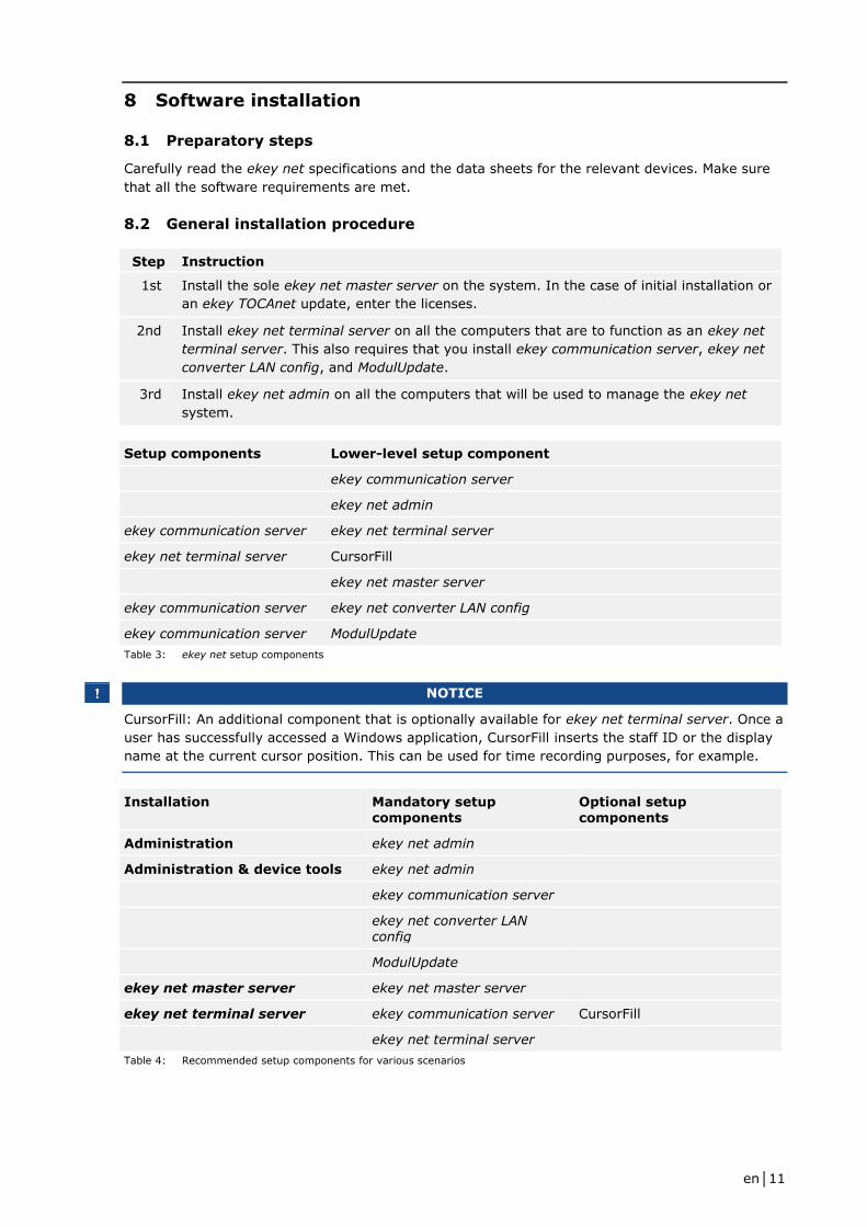
8.2 General installation procedure
Step Instruction
1st Install the sole ekey net master server on the system. In the case of initial installation or
an ekey TOCAnet update, enter the licenses.
2nd Install ekey net terminal server on all the computers that are to function as an ekey net
terminal server. This also requires that you install ekey communication server, ekey net
converter LAN config, and ModulUpdate.
3rd Install ekey net admin on all the computers that will be used to manage the ekey net
system.
Setup components Lower-level setup component
ekey communication server
ekey net admin
ekey communication server ekey net terminal server
ekey net terminal server CursorFill
ekey net master server
ekey communication server ekey net converter LAN config
ekey communication server ModulUpdate
Table 3: ekey net setup components
NOTICE
CursorFill: An additional component that is optionally available for ekey net terminal server. Once a
user has successfully accessed a Windows application, CursorFill inserts the staff ID or the display
name at the current cursor position. This can be used for time recording purposes, for example.
Installation Mandatory setup components
Optional setup components
Administration ekey net admin
Administration & device tools ekey net admin
ekey communication server
ekey net converter LAN config
ModulUpdate
ekey net master server ekey net master server
ekey net terminal server ekey communication server CursorFill
ekey net terminal server
Table 4: Recommended setup components for various scenarios
en│12
NOTICE
If you are installing an ekey net system on a single computer, select all the components apart from
CursorFill.
8.3 Initial installation
Step Instruction
1st Run the Setup.exe file.
2nd Select the language required for setup.
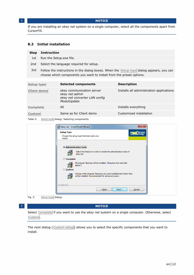
3rd Follow the instructions in the dialog boxes. When the Setup type dialog appears, you can
choose which components you want to install from the preset options.
Setup type Selected components Description
Client demo ekey communication server ekey net admin
ekey net converter LAN config ModulUpdate
Installs all administration applications
Complete All Installs everything
Custom Same as for Client demo Customized installation
Table 5: Setup type dialog: Selecting components
Fig. 5: Setup type dialog:
NOTICE
Select Complete if you want to use the ekey net system on a single computer. Otherwise, select
Custom.
The next dialog (Custom setup) allows you to select the specific components that you want to
install.
en│13
Fig. 6: Custom setup dialog
Step Instruction
1st Select the required components.
2nd In addition, use this dialog to define the database folder for the ekey net master server
and/or ekey net terminal server. C:\ekey netDB is used by default. Define which folder
the ekey net master server should use to store its data.
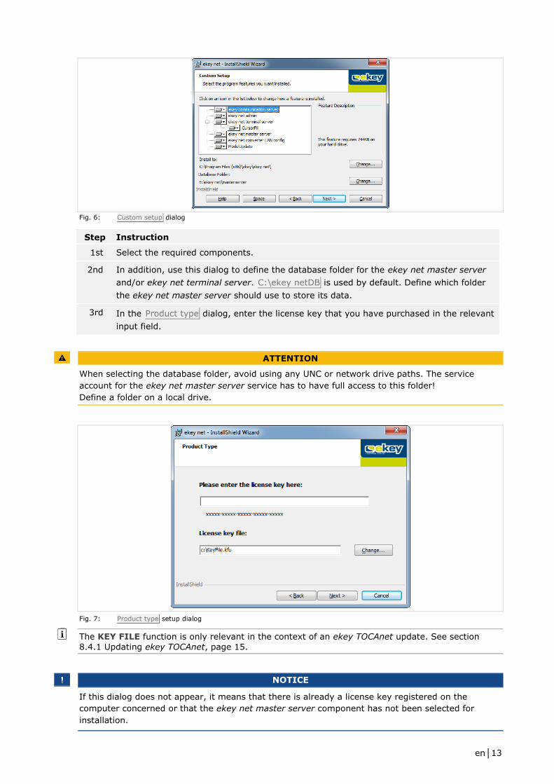
3rd In the Product type dialog, enter the license key that you have purchased in the relevant
input field.
ATTENTION
When selecting the database folder, avoid using any UNC or network drive paths. The service
account for the ekey net master server service has to have full access to this folder!
Define a folder on a local drive.
Fig. 7: Product type setup dialog
The KEY FILE function is only relevant in the context of an ekey TOCAnet update. See section
8.4.1 Updating ekey TOCAnet, page 15.
NOTICE
If this dialog does not appear, it means that there is already a license key registered on the
computer concerned or that the ekey net master server component has not been selected for
installation.
en│14
Step Instruction
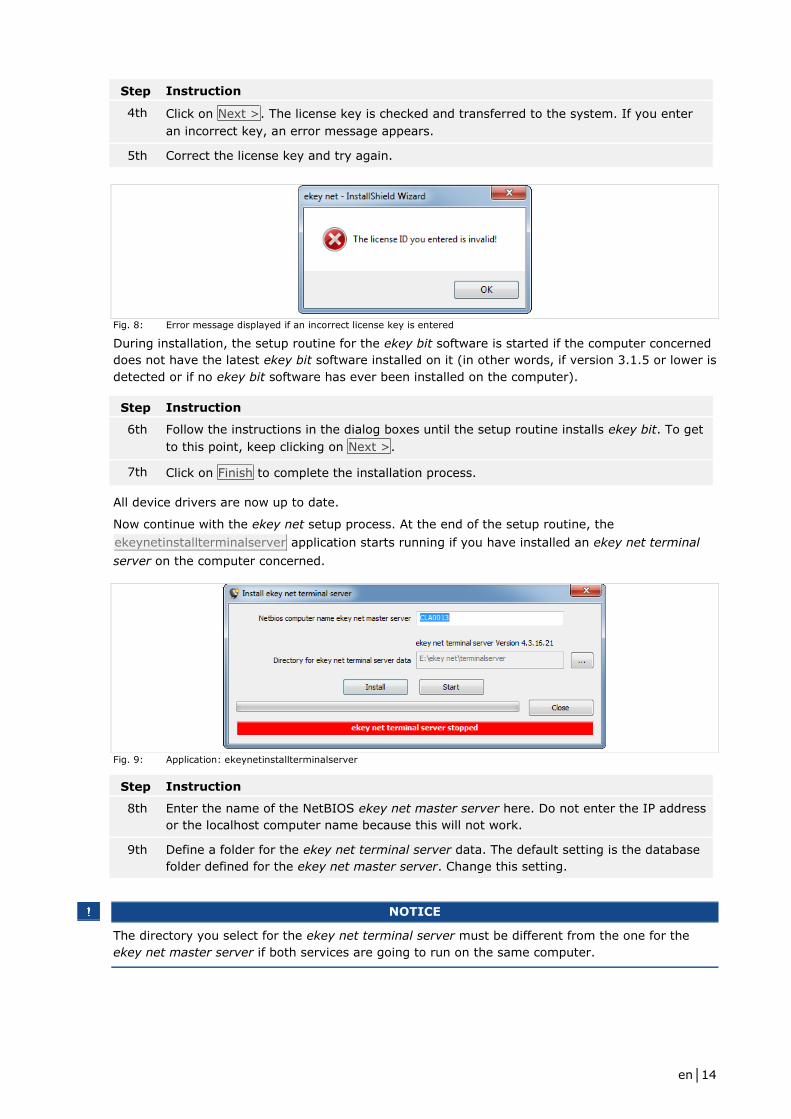
4th Click on Next >. The license key is checked and transferred to the system. If you enter
an incorrect key, an error message appears.
5th Correct the license key and try again.
Fig. 8: Error message displayed if an incorrect license key is entered
During installation, the setup routine for the ekey bit software is started if the computer concerned
does not have the latest ekey bit software installed on it (in other words, if version 3.1.5 or lower is
detected or if no ekey bit software has ever been installed on the computer).
Step Instruction
6th Follow the instructions in the dialog boxes until the setup routine installs ekey bit. To get
to this point, keep clicking on Next >.
7th Click on Finish to complete the installation process.
All device drivers are now up to date.
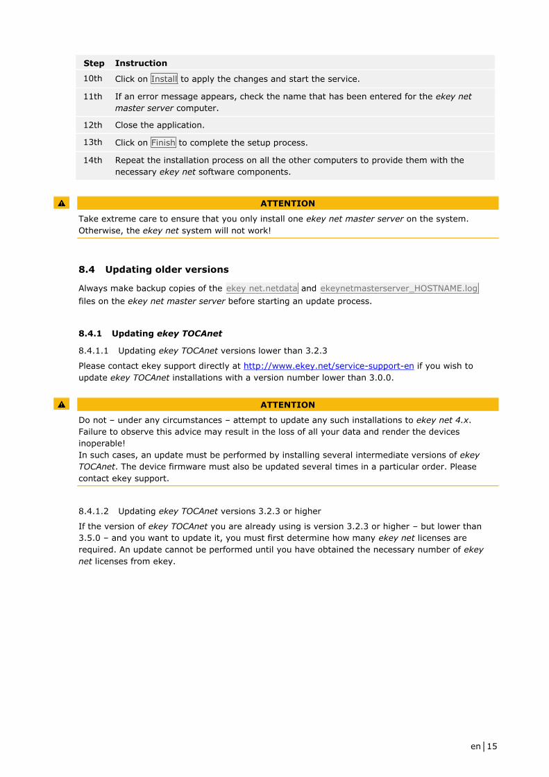
Now continue with the ekey net setup process. At the end of the setup routine, the
ekeynetinstallterminalserver application starts running if you have installed an ekey net terminal
server on the computer concerned.
Fig. 9: Application: ekeynetinstallterminalserver
Step Instruction
8th Enter the name of the NetBIOS ekey net master server here. Do not enter the IP address
or the localhost computer name because this will not work.
9th Define a folder for the ekey net terminal server data. The default setting is the database
folder defined for the ekey net master server. Change this setting.
NOTICE
The directory you select for the ekey net terminal server must be different from the one for the
ekey net master server if both services are going to run on the same computer.
en│15
Step Instruction
10th Click on Install to apply the changes and start the service.
11th If an error message appears, check the name that has been entered for the ekey net
master server computer.
12th Close the application.
13th Click on Finish to complete the setup process.
14th Repeat the installation process on all the other computers to provide them with the
necessary ekey net software components.
ATTENTION
Take extreme care to ensure that you only install one ekey net master server on the system.
Otherwise, the ekey net system will not work!
8.4 Updating older versions
Always make backup copies of the ekey net.netdata and ekeynetmasterserver_HOSTNAME.log
files on the ekey net master server before starting an update process.
8.4.1 Updating ekey TOCAnet
8.4.1.1 Updating ekey TOCAnet versions lower than 3.2.3
Please contact ekey support directly at http://www.ekey.net/service-support-en if you wish to
update ekey TOCAnet installations with a version number lower than 3.0.0.
ATTENTION
Do not – under any circumstances – attempt to update any such installations to ekey net 4.x.
Failure to observe this advice may result in the loss of all your data and render the devices
inoperable!
In such cases, an update must be performed by installing several intermediate versions of ekey
TOCAnet. The device firmware must also be updated several times in a particular order. Please
contact ekey support.
8.4.1.2 Updating ekey TOCAnet versions 3.2.3 or higher
If the version of ekey TOCAnet you are already using is version 3.2.3 or higher – but lower than
3.5.0 – and you want to update it, you must first determine how many ekey net licenses are
required. An update cannot be performed until you have obtained the necessary number of ekey
net licenses from ekey.
en│16
Step Instruction
1st To check how many licenses are required, use the ekeyNetUpdateCheck.exe program.
You will find this tool on the ekey net CD under checkUpdate.
2nd Copy the file into the ekey TOCAnet program directory on the computer that has the ekey
TOCAnet master server installed on it.
3rd Start the program. The tool determines how many licenses are required to run ekey net
on your system. It only detects those finger scanners that have been configured in the
current ekey TOCAnet database and have gone online at least once.
4th You will be prompted to save the ekeyLicenseRequest.txt file. Send this file to
[email protected]. You will then receive a KFU file from ekey. When you install the ekey
net master server, the Product type dialog will ask you for this file.
NOTICE
The update operation CANNOT be performed without this file. It is NOT possible to enter license
keys during an update. Instead, the KFU file has to be imported!
Step Instruction
5th Save the file from the e-mail.
6th Run the ekey net setup routine.
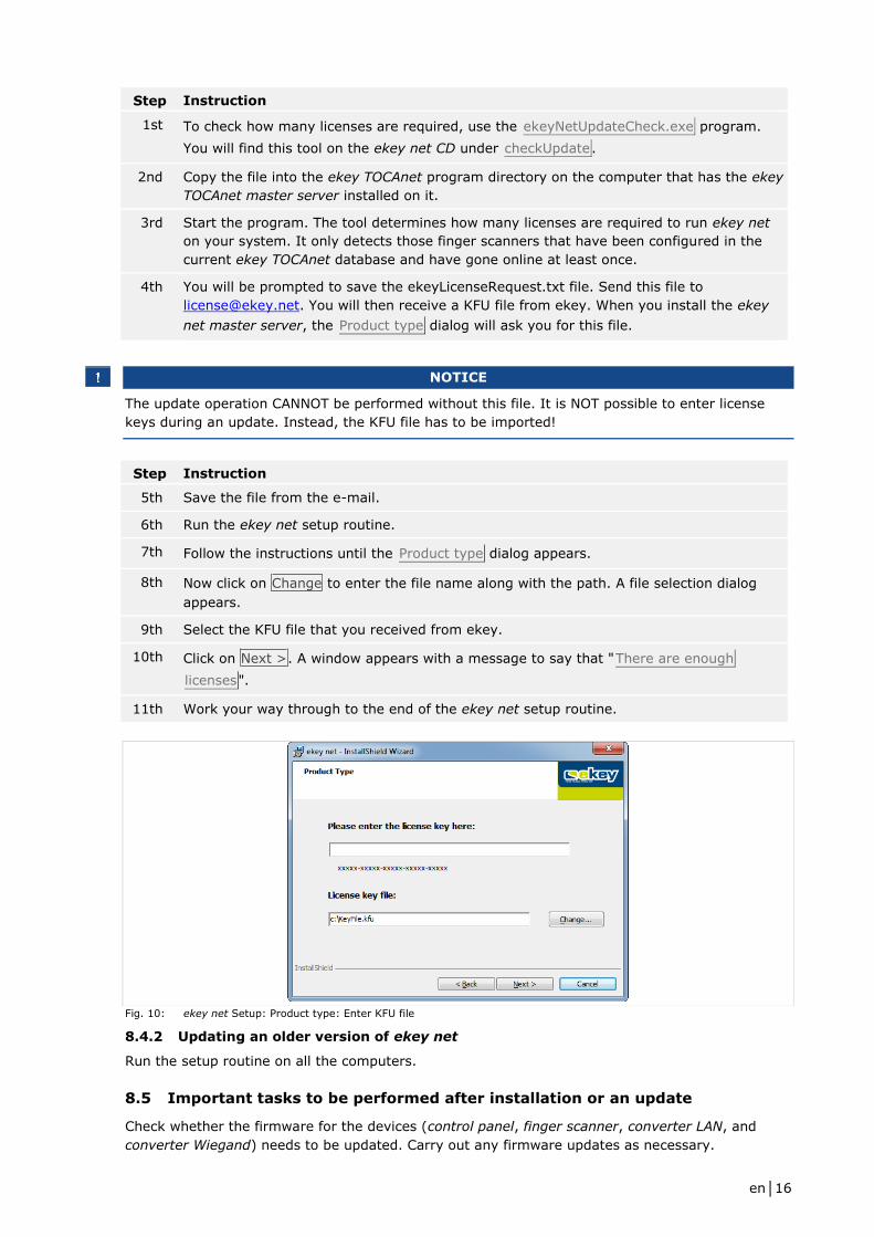
7th Follow the instructions until the Product type dialog appears.
8th Now click on Change to enter the file name along with the path. A file selection dialog
appears.
9th Select the KFU file that you received from ekey.
10th Click on Next >. A window appears with a message to say that "There are enough
licenses".
11th Work your way through to the end of the ekey net setup routine.
Fig. 10: ekey net Setup: Product type: Enter KFU file
8.4.2 Updating an older version of ekey net
Run the setup routine on all the computers.
8.5 Important tasks to be performed after installation or an update
Check whether the firmware for the devices (control panel, finger scanner, converter LAN, and
converter Wiegand) needs to be updated. Carry out any firmware updates as necessary.
en│17
8.6 Uninstalling the software
Step Instruction
1st Go to Control Panel – Add or Remove Programs (Windows XP) or Control Panel –
Uninstall a program (Windows Vista and higher) and start the ekey net setup routine.
2nd Select Uninstall.
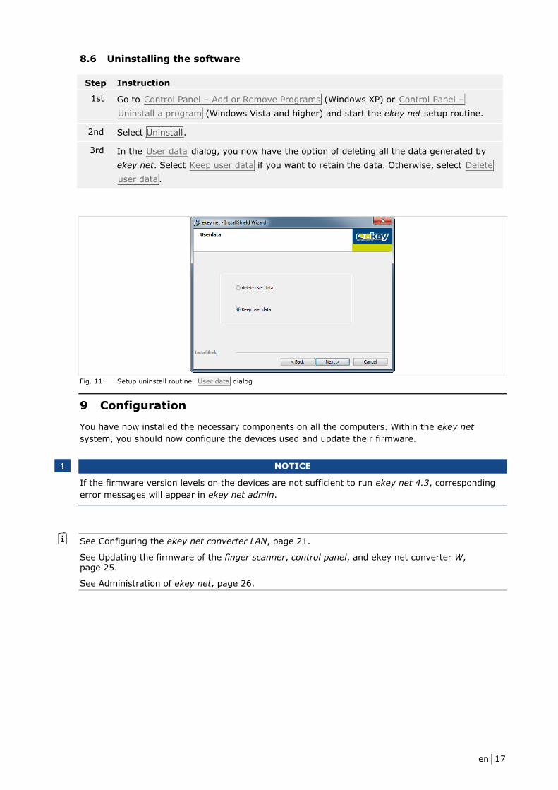
3rd In the User data dialog, you now have the option of deleting all the data generated by
ekey net. Select Keep user data if you want to retain the data. Otherwise, select Delete
user data.
Fig. 11: Setup uninstall routine. User data dialog
9 Configuration
You have now installed the necessary components on all the computers. Within the ekey net
system, you should now configure the devices used and update their firmware.
NOTICE
If the firmware version levels on the devices are not sufficient to run ekey net 4.3, corresponding
error messages will appear in ekey net admin.
See Configuring the ekey net converter LAN, page 21.
See Updating the firmware of the finger scanner, control panel, and ekey net converter W, page 25.
See Administration of ekey net, page 26.

en│18
9.1 Managing licenses
You will find the license management tool under Start – All Programs – ekey – ekey licensing –
License Manager. The license manager is used to administer the licenses for ekey products. You
need to obtain one or more license keys from ekey before you can activate a license. The process
of activating a license key links it to the specified user data and the particular computer concerned.
A license key consists of 25 alphanumeric characters (0-9 and A-Z), which are divided into blocks
of five separated by hyphens,
e.g., YJL2P-Z3Q2Q-S4S71-RJ4VK-VTU6G.
NOTICE
ekey net licenses can be activated up to a maximum of three times (online or offline). This may be
necessary if, for example, the software has to be reinstalled following relocation. Before attempting
to activate a license for the fourth time, you must contact ekey.
ATTENTION
Make a note of the e-mail address used for license activation.
Once activated, licenses cannot be reactivated using a different e-mail address.
E-mail addresses of specific people may not be available at a later date due to staff turnover.
Check whether you will still be able to access them. Ideally, you should use a general company
address.
When you add an ekey net license key (light, com, or business), a 30-day trial period is enabled for
the license key concerned. The first step is to set up the system completely. Do not activate the
license on the selected PC until you are sure that your system is functioning correctly. Exception: If
the license key was present on the system previously but has been deleted and added again, there
will be no trial period!
ATTENTION
If the trial period for the license keys has expired but the keys have not been activated, you will
not be able to make any changes to the ekey net database or forward changes to the ekey net
terminal server!
The license data that is stored on the computer cannot be transferred to another computer or
copied back after reinstalling the operating system. In this case, you must add the license key
again and then activate it.
ekey net licenses can only be managed on the computer that has the ekey net master server
installed on it. The ekey net system will not be able to use any license key that is added on a
different computer.
Changing the system time or host name will invalidate any license that has not yet been activated.
In the main License Manager dialog, you will see a list of licensed ekey products on the left
together with a summary. Whenever a product in the left-hand list is selected, the details of the
license appear in the list on the right.
en│19
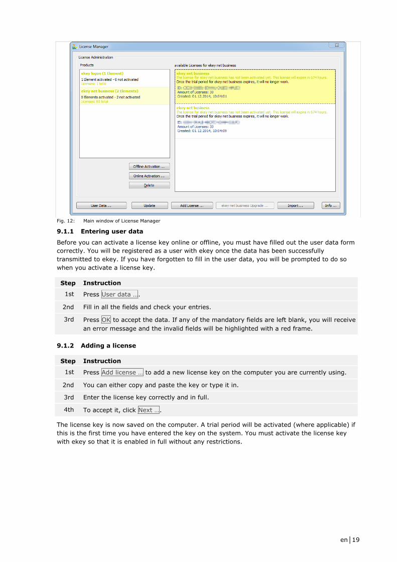
Fig. 12: Main window of License Manager
9.1.1 Entering user data
Before you can activate a license key online or offline, you must have filled out the user data form
correctly. You will be registered as a user with ekey once the data has been successfully
transmitted to ekey. If you have forgotten to fill in the user data, you will be prompted to do so
when you activate a license key.
Step Instruction
1st Press User data ….
2nd Fill in all the fields and check your entries.
3rd Press OK to accept the data. If any of the mandatory fields are left blank, you will receive
an error message and the invalid fields will be highlighted with a red frame.
9.1.2 Adding a license
Step Instruction
1st Press Add license … to add a new license key on the computer you are currently using.
2nd You can either copy and paste the key or type it in.
3rd Enter the license key correctly and in full.
4th To accept it, click Next ….
The license key is now saved on the computer. A trial period will be activated (where applicable) if
this is the first time you have entered the key on the system. You must activate the license key
with ekey so that it is enabled in full without any restrictions.

en│20
9.1.3 Activating a license
9.1.3.1 Online activation
If the computer running License Manager is connected to the Internet, you can easily activate the
license key online. If the computer does not have an Internet connection, the license key is
activated offline.
9.1.3.2 Offline activation
During offline activation, a file with the extension *.req is created.
Step Instruction
1st Save this file.
2nd Copy the file onto a computer from which you are able to send e-mails.
3rd Draft an e-mail with the subject license request V2, enter [email protected] as the
recipient e-mail address, and attach the "*.req" file to the e-mail.
4th Send the e-mail. You will receive a reply from ekey with an "*.act" file attachment.
5th Copy this file onto the computer where you started the activation process.
6th Press Import … in the main window of License Manager to complete the offline activation
process.
9.1.4 Upgrading your license to ekey net business
If you wish to upgrade an ekey net light or ekey net com installation to ekey net business you must
purchase the necessary ekey net business upgrade license keys. You cannot perform this operation
using an ekey net business license key.
Step Instruction
1st Select ekey net business upgrade … to start the process.
2nd Follow the instructions. The first information dialog will tell you how many finger scanners
need an upgrade license key.
3rd In the next dialog, enter all the necessary keys. During the next step, the software
attempts to upgrade the license online. If this is not possible, you must carry out the
activation process offline.
4th Once the license has been successfully upgraded to ekey net business, restart the ekey
net master server service to convert the ekey net database.
See Offline activation, page 20.
9.2 Starting and stopping ekey net services
Like all other Windows services, ekey net services are managed using services.msc. These are as
follows:
□ ekey communication server
□ ekey net master server
□ ekey net terminal server
ATTENTION
You must stop the ekey service guard service before stopping an ekey net service. Otherwise, the
services will not be terminated for good and will restart again after a short period.
en│21
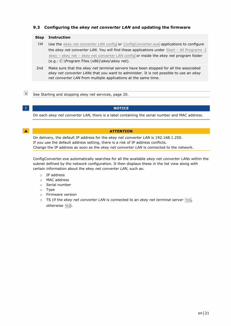
9.3 Configuring the ekey net converter LAN and updating the firmware
Step Instruction
1st Use the ekey net converter LAN config or ConfigConverter.exe applications to configure
the ekey net converter LAN. You will find these applications under Start – All Programs –
ekey – ekey net – ekey net converter LAN config or inside the ekey net program folder
(e.g.: C:\Program Files (x86)\ekey\ekey net).
2nd Make sure that the ekey net terminal servers have been stopped for all the associated
ekey net converter LANs that you want to administer. It is not possible to use an ekey
net converter LAN from multiple applications at the same time.
See Starting and stopping ekey net services, page 20.
NOTICE
On each ekey net converter LAN, there is a label containing the serial number and MAC address.
ATTENTION
On delivery, the default IP address for the ekey net converter LAN is 192.168.1.250.
If you use the default address setting, there is a risk of IP address conflicts.
Change the IP address as soon as the ekey net converter LAN is connected to the network.
ConfigConverter.exe automatically searches for all the available ekey net converter LANs within the
subnet defined by the network configuration. It then displays these in the list view along with
certain information about the ekey net converter LAN, such as:
□ IP address
□ MAC address
□ Serial number
□ Type
□ Firmware version
□ TS (if the ekey net converter LAN is connected to an ekey net terminal server Yes,
otherwise No).
en│22
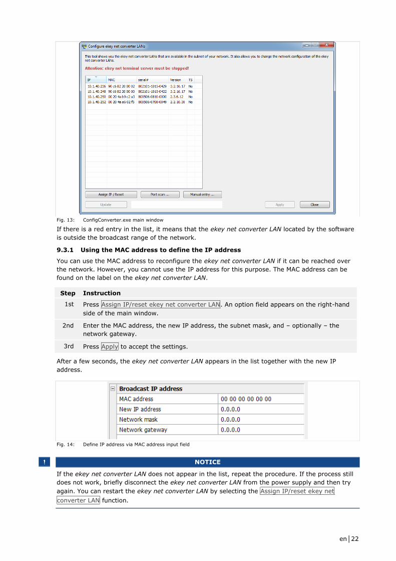
Fig. 13: ConfigConverter.exe main window
If there is a red entry in the list, it means that the ekey net converter LAN located by the software
is outside the broadcast range of the network.
9.3.1 Using the MAC address to define the IP address
You can use the MAC address to reconfigure the ekey net converter LAN if it can be reached over
the network. However, you cannot use the IP address for this purpose. The MAC address can be
found on the label on the ekey net converter LAN.
Step Instruction
1st Press Assign IP/reset ekey net converter LAN. An option field appears on the right-hand
side of the main window.
2nd Enter the MAC address, the new IP address, the subnet mask, and – optionally – the
network gateway.
3rd Press Apply to accept the settings.
After a few seconds, the ekey net converter LAN appears in the list together with the new IP
address.
Fig. 14: Define IP address via MAC address input field
NOTICE
If the ekey net converter LAN does not appear in the list, repeat the procedure. If the process still
does not work, briefly disconnect the ekey net converter LAN from the power supply and then try
again. You can restart the ekey net converter LAN by selecting the Assign IP/reset ekey net
converter LAN function.

en│23
9.3.2 Defining the IP address by selecting it from the list
Fig. 15: Define IP address by selecting it from the list
Step Instruction
1st If the ekey net converter LAN can be found in the list, click on it.
2nd You can change its configuration in the field on the right.
3rd Once you have finished making all the changes to the configuration, press Apply. The
settings are applied. The ekey net converter LAN disappears from the list and then
reappears after a few seconds with the new network configuration.
9.3.3 Updating the firmware
On delivery, the ekey net software includes the latest firmware for the ekey net converter LANs.
However, the ekey net converter LANs may have been delivered with an older firmware version.
If the firmware version displayed in the overview list is lower than the one shown on Update
2.2.5.21 (in the case of ekey net 4.3.0: version 2.2.1.11), you can update the firmware. Click on
the ekey net converter LAN in the list and then press Update 2.2.5.21. The button is only enabled
if:
□ The ekey net converter LAN has been configured correctly for the network and can be
reached
□ The firmware version of the ekey net converter LAN is lower than the one shown on the
button
□ The ekey net terminal server service has been stopped
ATTENTION
If an ekey net converter LAN has a firmware version lower than 2.0.0.0 (e.g., 1.6.1.16), you must
not attempt to update the firmware under any circumstances. For details of how to proceed, please
contact our support team.
ATTENTION
Never interrupt the power supply or data connection during the firmware update. In a worst-case
scenario, the device will have to be reprogrammed by ekey.
9.3.4 Checking the function of ekey net converter LANs on the network
Test whether the IP address of the ekey net converter LAN can be reached by sending a ping. The
ekey net converter LANs will only work properly as part of the ekey net installation if the relevant
UDP ports that link the ekey net terminal server to the ekey net converter LAN are free. You can
use the ekey net converter LAN config application to check whether your network supports this
type of communication.

en│24
Step Instruction
1st Press Port scan …. A dialog appears so that you can check the IP address of an ekey net
converter LAN.
2nd Enter the ekey net converter LAN IP address that you want to check.
3rd Press Check to start the checking process.
All the necessary UDP ports are checked. If all the port numbers reply with OK, the ekey net
converter LAN is ready for use.
9.3.5 ekey net converter LAN not found
Your network may use other IP addresses, e.g., if the subnet differs. In this case, you can enter
the ekey net converter LAN yourself by selecting Manual entry. However, it may still show up if it is
located using a MAC address broadcast.
Various routers or switches may block the ekey net converter LAN search:
Reason Action
The IP address of the ekey
net converter LAN must be
static.
Do not use DHCP.
The firewall or router does
not allow broadcasts.
Deactivate the firewall or change the router configuration.
No exceptions have been
added for the firewall or
router. Ports 58000-58018
have not been entered.
Deactivate the firewall and add your exceptions, or change the
router configuration.
The ports have been reserved
by another program.
Download a port scanner (e.g., TCPView from Sysinternals) to see
which UDP ports are required by which program.
Use an MS-DOS prompt to test whether the ekey net converter
LAN can be reached by sending a ping.
The PC is in the same subnet
as the ekey net converter
LAN and cannot be reached
by sending a ping.
Look at the two LEDs on the ekey net converter LAN. The power
LED is on the left and the activity LED is on the right. If neither
lights up, there is a problem with the power supply. If both flash
orange, there is a firmware fault.
Disconnect the ekey net converter LAN from the power supply
system.
Disconnect the switch from the power supply system.
Try assigning a different IP address to the ekey net converter LAN
by selecting Assign IP/reset ekey net converter LAN. Enter the
MAC address manually or click Manual selection….
Remove the check mark next to Only for analysis in
ConfigConverter.exe.
The device's own IP address
has been changed, e.g., on a
notebook.
Restart the ekey communication server service.
Check that all the ekey services are running as well as Message
Queuing.
en│25
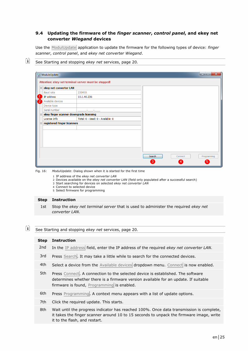
9.4 Updating the firmware of the finger scanner, control panel, and ekey net
converter Wiegand devices
Use the ModulUpdate application to update the firmware for the following types of device: finger
scanner, control panel, and ekey net converter Wiegand.
See Starting and stopping ekey net services, page 20.
Fig. 16: ModulUpdate: Dialog shown when it is started for the first time
1 IP address of the ekey net converter LAN 2 Devices available on the ekey net converter LAN (field only populated after a successful search)
3 Start searching for devices on selected ekey net converter LAN
4 Connect to selected device
5 Select firmware for programming
Step Instruction
1st Stop the ekey net terminal server that is used to administer the required ekey net
converter LAN.
See Starting and stopping ekey net services, page 20.
Step Instruction
2nd In the IP address field, enter the IP address of the required ekey net converter LAN.
3rd Press Search. It may take a little while to search for the connected devices.
4th Select a device from the Available devices dropdown menu. Connect is now enabled.
5th Press Connect. A connection to the selected device is established. The software
determines whether there is a firmware version available for an update. If suitable
firmware is found, Programming is enabled.
6th Press Programming. A context menu appears with a list of update options.
7th Click the required update. This starts.
8th Wait until the progress indicator has reached 100%. Once data transmission is complete,
it takes the finger scanner around 10 to 15 seconds to unpack the firmware image, write
it to the flash, and restart.
en│26
NOTICE
There are several different options for updating the firmware:
□ Update to a more recent version
□ Revert to an older version
□ Replace with an identical version
10 Administration of ekey net
ekey net is administered using the ekey net admin application. The Windows Start menu contains
two links for starting ekey net admin. The ekey net admin demo link starts ekey net admin in
demo mode. The ekey net admin link starts ekey net admin in normal mode.
NOTICE
Please remember that each object name attribute that you enter (first name, last name, display
name, passwords, etc.) in the ekey net system is case sensitive.
Any change that is made to the ekey net database in ekey net admin is immediately applied to the
ekey net master server. To send the changes to all the devices, press Send changes to devices.
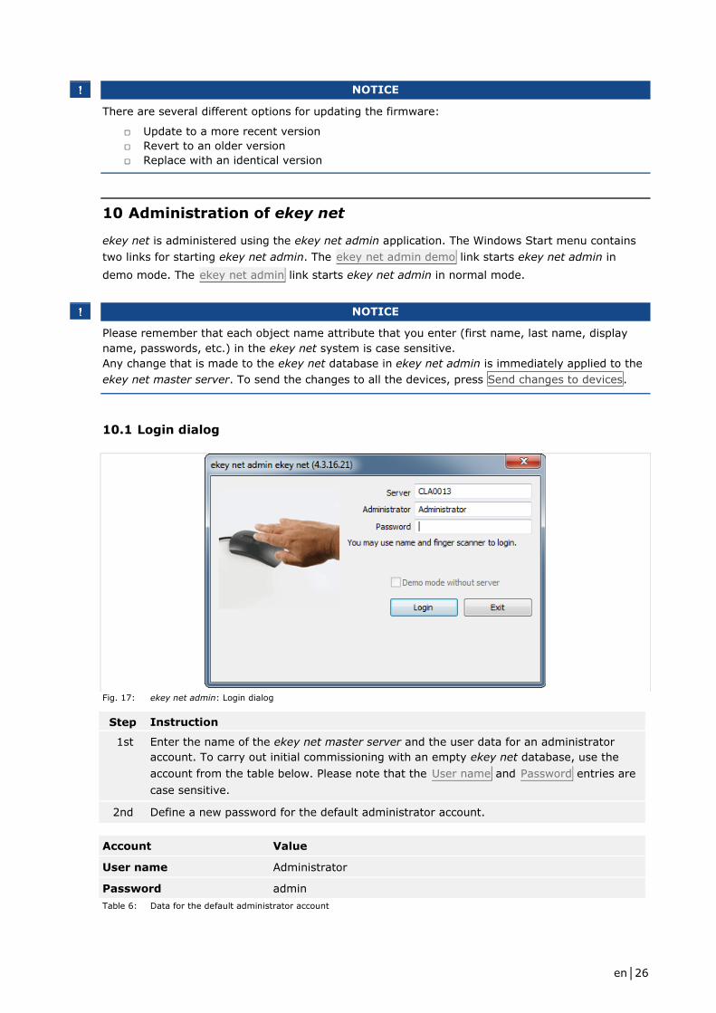
10.1 Login dialog
Fig. 17: ekey net admin: Login dialog
Step Instruction
1st Enter the name of the ekey net master server and the user data for an administrator
account. To carry out initial commissioning with an empty ekey net database, use the
account from the table below. Please note that the User name and Password entries are
case sensitive.
2nd Define a new password for the default administrator account.
Account Value
User name Administrator
Password admin
Table 6: Data for the default administrator account
en│27
If you are carrying out initial commissioning, a basic configuration wizard will appear once you
have successfully logged in. Otherwise, the start view will be displayed.
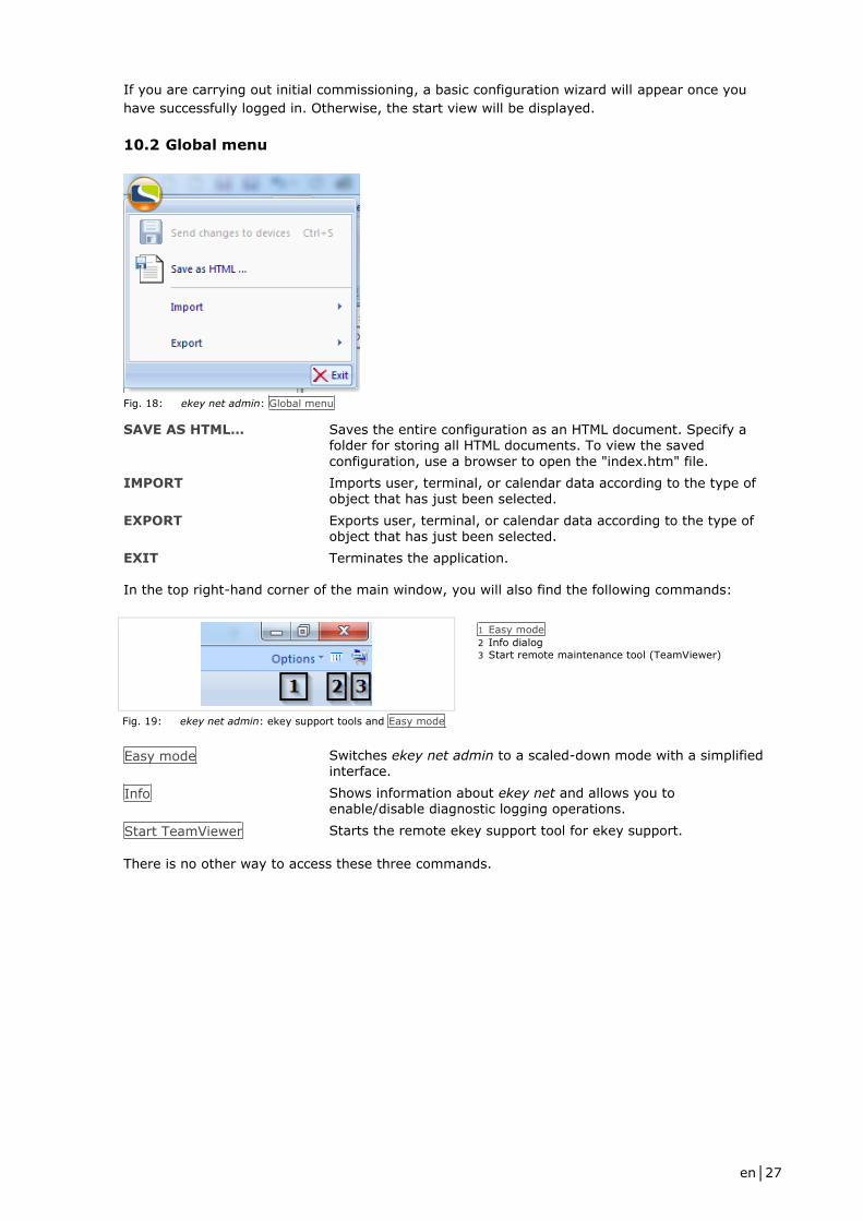
10.2 Global menu
Fig. 18: ekey net admin: Global menu
SAVE AS HTML… Saves the entire configuration as an HTML document. Specify a folder for storing all HTML documents. To view the saved
configuration, use a browser to open the "index.htm" file.
IMPORT Imports user, terminal, or calendar data according to the type of object that has just been selected.
EXPORT Exports user, terminal, or calendar data according to the type of object that has just been selected.
EXIT Terminates the application.
In the top right-hand corner of the main window, you will also find the following commands:
1 Easy mode
2 Info dialog
3 Start remote maintenance tool (TeamViewer)
Fig. 19: ekey net admin: ekey support tools and Easy mode
Easy mode Switches ekey net admin to a scaled-down mode with a simplified interface.
Info Shows information about ekey net and allows you to enable/disable diagnostic logging operations.
Start TeamViewer Starts the remote ekey support tool for ekey support.
There is no other way to access these three commands.

en│28
10.3 START menu
Fig. 20: ekey net admin: START menu
Start wizard Starts the wizard for configuring ekey net. The wizard will keep opening automatically whenever you start the application until
you have made all the minimum settings required.
Languages Allows you to change the language. After changing the language, you must restart the application to activate it.
Send changes to devices This button is enabled as soon as you make changes to the
system. Press this button to transmit the current database to all devices. Only the changes are updated. No update is performed on devices that are unaffected by data changes. Before the changes are forwarded, the ekey net master server carries out a consistency check to identify any errors in the settings. If problems are detected, a dialog appears with details of these.
Help Opens this document.
See The wizard, page 73.
See Consistency check, page 81.
NOTICE
You can press CTRL + Shift to enable Send changes to devices and force a full update. All data is
then updated on all finger scanners.
NOTICE
Send changes to devices and Help are available in the menus of all views.
en│29
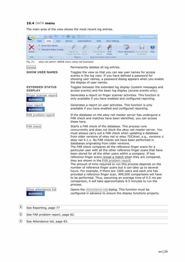
10.4 DATA menu
The main area of the view shows the most recent log entries.
Fig. 21: ekey net admin: DATA menu (ekey net business)
Delete Permanently deletes all log entries.
SHOW USER NAMES Toggles the view so that you can see user names for access events in the log view. If you have defined a password for
showing user names, a password dialog appears when you enable the display of user names.
EXTENDED STATUS DISPLAY
Toggles between the extended log display (system messages and access events) and the basic log display (access events only).
Finger scanner report
Generates a report on finger scanner activities. This function is only available if you have enabled and configured reporting.
User report
Generates a report on user activities. This function is only available if you have enabled and configured reporting.
FAR problem report If the database on the ekey net master server has undergone a FAR check and matches have been identified, you can access these here.
FAR check Starts a FAR check of the database. This process runs concurrently and does not block the ekey net master server. You
must always carry out a FAR check when updating a database from older versions of ekey net or ekey TOCAnet, e.g., versions ≤ ekey net 4.1.x. No FAR checks will have been performed in databases originating from older versions. The FAR check compares all the reference finger scans for a particular user with all the other reference finger scans that have been stored for all the other users within a company. If two
reference finger scans reveal a match when they are compared,
they are shown in the FAR problem report.
The amount of time required to run this process depends on the number of reference finger scans but it can take up to several
hours. For example, if there are 1000 users and each one has provided a reference finger scan, 999,000 comparisons will have to be performed. Thus, assuming an average time of 0.5 ms per comparison, it will take approximately 8.5 minutes to run the
process.
Show attendance list
Opens the Attendance list dialog. This function must be
configured in advance to ensure the display functions properly.
See Reporting, page 77
See FAR problem report, page 82.
See Attendance list, page 83.
en│30
ATTENTION
FAR problems are a source of access errors.
Therefore, you must resolve them immediately.
Delete the affected reference finger scans and register (enroll) them again.
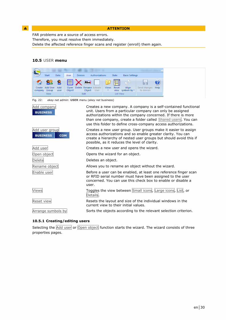
10.5 USER menu
Fig. 22: ekey net admin: USER menu (ekey net business)
Add company
Creates a new company. A company is a self-contained functional
unit. Users from a particular company can only be assigned authorizations within the company concerned. If there is more
than one company, create a folder called Shared users. You can
use this folder to define cross-company access authorizations.
Add user group
Creates a new user group. User groups make it easier to assign access authorizations and so enable greater clarity. You can create a hierarchy of nested user groups but should avoid this if
possible, as it reduces the level of clarity.
Add user Creates a new user and opens the wizard.
Open object Opens the wizard for an object.
Delete Deletes an object.
Rename object Allows you to rename an object without the wizard.
Enable user Before a user can be enabled, at least one reference finger scan
or RFID serial number must have been assigned to the user concerned. You can use this check box to enable or disable a user.
Views Toggles the view between Small icons, Large icons, List, or
Details.
Reset view Resets the layout and size of the individual windows in the current view to their initial values.
Arrange symbols by Sorts the objects according to the relevant selection criterion.
10.5.1 Creating/editing users
Selecting the Add user or Open object function starts the wizard. The wizard consists of three
properties pages.

en│31
10.5.1.1 Edit user properties page
Define the user properties here.
Fig. 23: ekey net admin: Edit user : Edit user
FIRST NAME Enter the user's forename.
LAST NAME Enter the user's surname.
DEFINE THIS USER TO BE AN ADMINISTRATOR OF THE ACCESS CONTROL SYSTEM
Specify whether or not this user should have administrator rights. If so, specify a password.
NAME Enter the display name for the user. This consists of the person's last name and first name separated by a comma (e.g., "Doe, John"). The display name is used as the login name for ekey net
admin. The entry is case sensitive. Whenever a change is made to the user's first name/last name, this field is modified automatically.
PASSWORD Define the password if the user has administration rights.
USER GROUPS Define the user groups to which this user is to belong.
10.5.1.2 Enroll finger properties page
This page allows you to enroll and delete reference finger scans, assign events to them, and specify
their level of importance.
NOTICE
It depends on how your system is configured as to whether the Atmel, the Authentec, or both
fingerprint types will be displayed:
□ If the system only features Atmel finger scanners and only contains Atmel reference finger
scans, only the Atmel fingerprint will be available for selection
□ If the system only features Authentec finger scanners and only contains Authentec
reference finger scans, only the Authentec fingerprint will be available for selection
□ In combined systems, both fingerprint types will be available
See Control for the ekey bit/ekey net finger scanner, page 8.
en│32
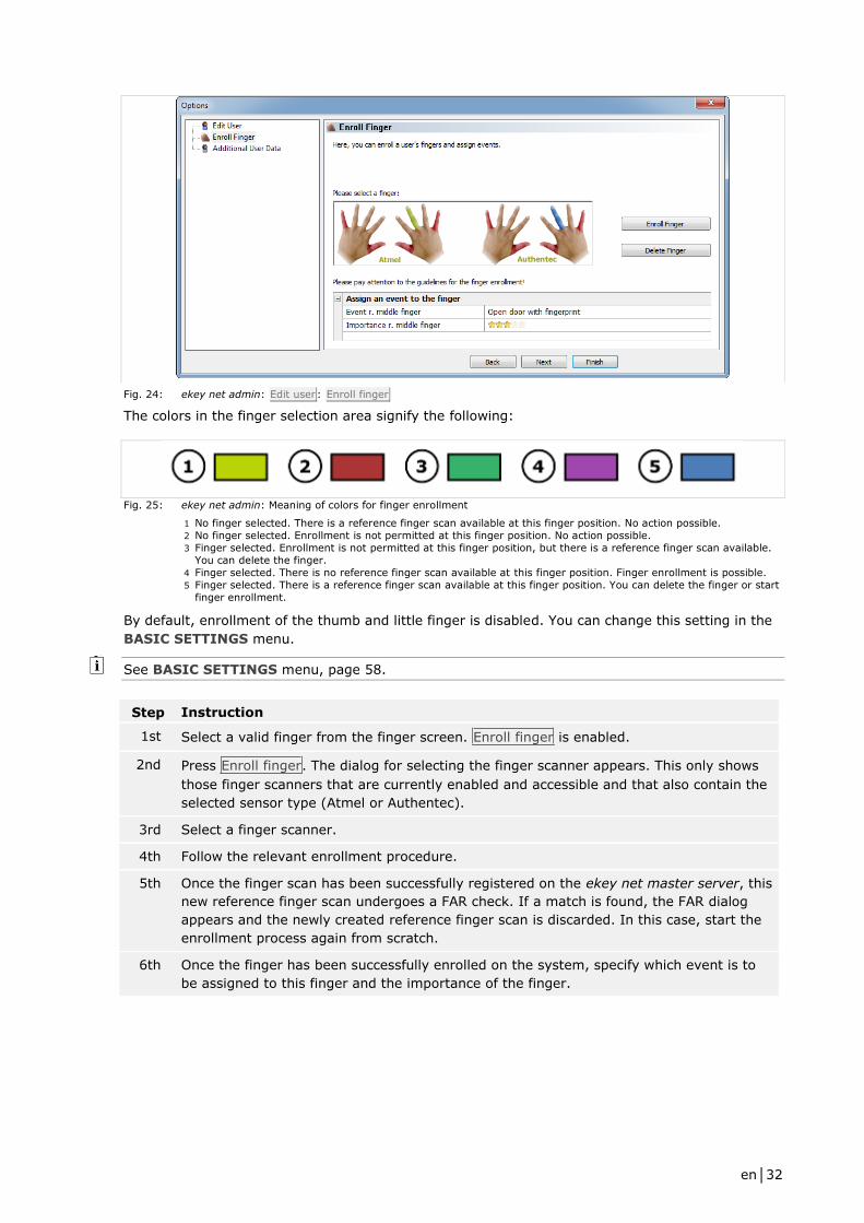
Fig. 24: ekey net admin: Edit user : Enroll finger
The colors in the finger selection area signify the following:
Fig. 25: ekey net admin: Meaning of colors for finger enrollment
1 No finger selected. There is a reference finger scan available at this finger position. No action possible.
2 No finger selected. Enrollment is not permitted at this finger position. No action possible.
3 Finger selected. Enrollment is not permitted at this finger position, but there is a reference finger scan available.
You can delete the finger.
4 Finger selected. There is no reference finger scan available at this finger position. Finger enrollment is possible.
5 Finger selected. There is a reference finger scan available at this finger position. You can delete the finger or start
finger enrollment.
By default, enrollment of the thumb and little finger is disabled. You can change this setting in the
BASIC SETTINGS menu.
See BASIC SETTINGS menu, page 58.
Step Instruction
1st Select a valid finger from the finger screen. Enroll finger is enabled.
2nd Press Enroll finger. The dialog for selecting the finger scanner appears. This only shows
those finger scanners that are currently enabled and accessible and that also contain the
selected sensor type (Atmel or Authentec).
3rd Select a finger scanner.
4th Follow the relevant enrollment procedure.
5th Once the finger scan has been successfully registered on the ekey net master server, this
new reference finger scan undergoes a FAR check. If a match is found, the FAR dialog
appears and the newly created reference finger scan is discarded. In this case, start the
enrollment process again from scratch.
6th Once the finger has been successfully enrolled on the system, specify which event is to
be assigned to this finger and the importance of the finger.

en│33
Fig. 26: ekey net admin: Edit user : Select finger scanner for finger enrollment
NOTICE
If you select an Atmel finger, only Atmel finger scanners will be made available for selection. If you
select an Authentec finger, only Authentec finger scanners will be made available for selection.
You must follow a specific enrollment procedure according to the type of finger scanner you have
selected:
Finger scanner Description
Atmel USB finger scanner Enrollment dialog with standard biometrics. The best result is taken from up to eight finger scans. You must exit the dialog manually.
Authentec USB finger
scanner
Enrollment dialog with improved biometrics. The best result is taken from at least three finger scans. As soon as an optimum quality result is detected, the dialog closes automatically.
Atmel RS-485 finger
scanner
Standard biometrics. As soon as a finger scan meets the minimum requirements, it is used.
Authentec RS-485 finger
scanner
Improved biometrics. The best result is taken from at least three finger scans. As soon as an optimum quality result is detected, the enrollment process is terminated.
Enrollment station Enrollment dialog with improved biometrics. The best result is taken from at least three finger scans. As soon as an optimum quality result is detected, the dialog closes automatically.
Table 7: Finger enrollment dialogs and finger scanner types
See FAR problem report, page 82.
en│34
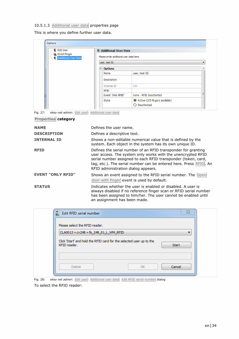
10.5.1.3 Additional user data properties page
This is where you define further user data.
Fig. 27: ekey net admin: Edit user : Additional user data
Properties category
NAME Defines the user name.
DESCRIPTION Defines a descriptive text.
INTERNAL ID Shows a non-editable numerical value that is defined by the system. Each object in the system has its own unique ID.
RFID Defines the serial number of an RFID transponder for granting
user access. The system only works with the unencrypted RFID serial number assigned to each RFID transponder (token, card,
tag, etc.). The serial number can be entered here. Press RFID. An
RFID administration dialog appears.
EVENT "ONLY RFID" Shows an event assigned to the RFID serial number. The Open
door with finger event is used by default.
STATUS Indicates whether the user is enabled or disabled. A user is always disabled if no reference finger scan or RFID serial number has been assigned to him/her. The user cannot be enabled until
an assignment has been made.
Fig. 28: ekey net admin: Edit user : Additional user data : Edit RFID serial number dialog
To select the RFID reader:

en│35
See BASIC SETTINGS – OPTIONS, page 58.
Follow the steps described below to define the RFID properties:
Step Instruction
1st Select an RFID reader.
2nd Press Start.
3rd Hold the RFID transponder in front of the reader until the serial number is detected.
Visual/acoustic feedback is provided as soon as the serial number has been read. The
serial number is shown as a hexadecimal string in the write-protected text field. If the
serial number is already in use on the system, you will get an error message.
4th Press OK to enter the serial number on the system. Press Delete to delete an existing
serial number from the system.
Validity period category
VALID FROM Specify the validity of this user object by defining the beginning of the access period.
VALID UNTIL Specify the validity of this user object by defining the end of the access period.
Additional user data category
These fields are only available if you have configured the user fields.
See BASIC SETTINGS – USER DATA, page 68.
10.6 TERMINALS menu
This view allows you to map the topography of the devices. Use it to define the following:
□ Which devices are connected to which ekey net converter LANs
□ Which devices are assigned to which access points
□ Which ekey net converter LAN is connected to which ekey net terminal server
□ Etc.
The best way to search for and configure the devices is to use the wizard.
Fig. 29: ekey net admin: TERMINALS menu (ekey net business)
Start wizard Starts the wizard for configuring ekey net. The wizard will keep opening automatically whenever you start the application until all
the minimum settings have been made.
See The wizard, page 73.
en│36
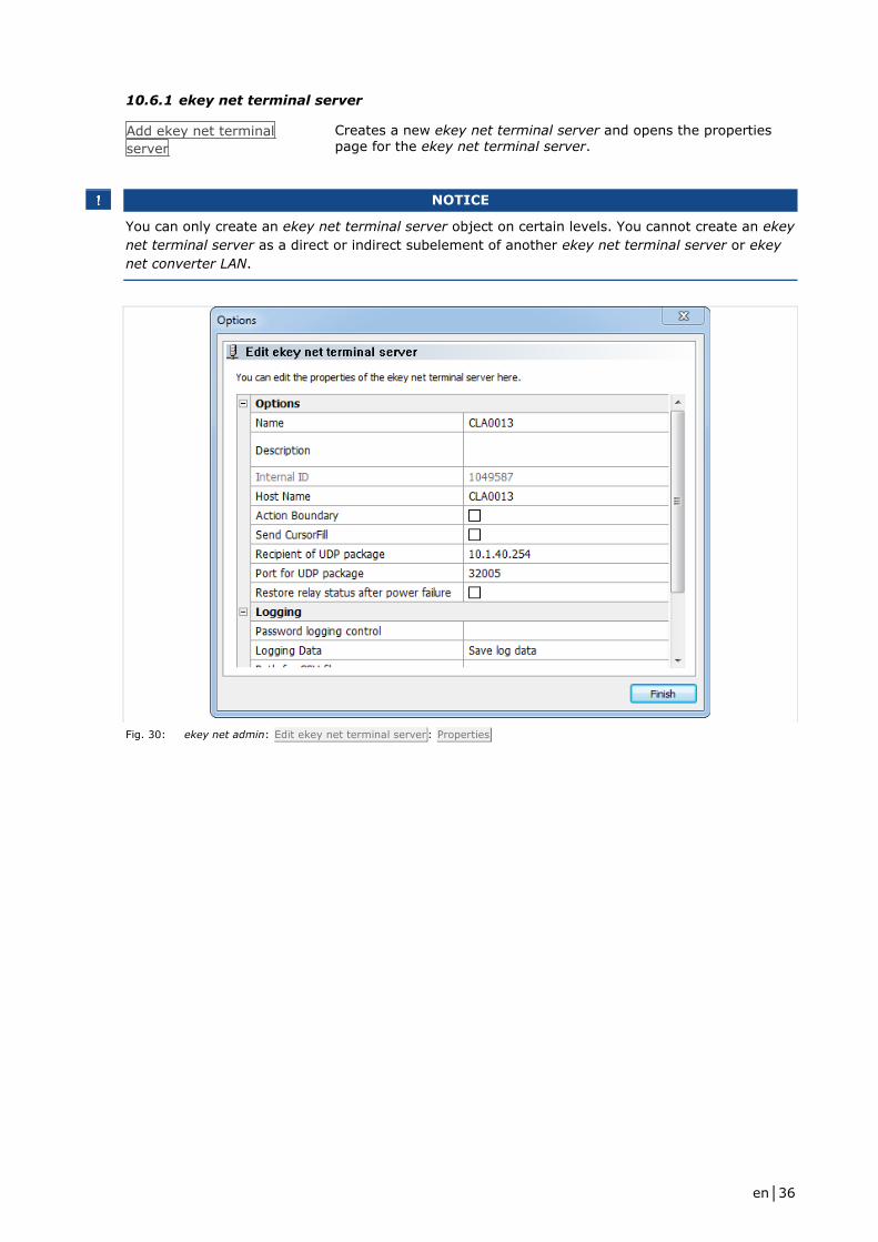
10.6.1 ekey net terminal server
Add ekey net terminal
server
Creates a new ekey net terminal server and opens the properties page for the ekey net terminal server.
NOTICE
You can only create an ekey net terminal server object on certain levels. You cannot create an ekey
net terminal server as a direct or indirect subelement of another ekey net terminal server or ekey
net converter LAN.
Fig. 30: ekey net admin: Edit ekey net terminal server : Properties

en│37
10.6.1.1 Editing an ekey net terminal server
Properties category
NAME Define the display name for the ekey net terminal server.
DESCRIPTION Define a description text.
INTERNAL ID Shows a non-editable numerical value that is defined by the system. Each object in the system has its own unique ID.
HOST NAME NetBIOS host name of the computer where the ekey net terminal server is installed. This must be resolvable in the network using the DNS and via NetBIOS. Do not enter an IP address here.
ACTION BOUNDARY Specify whether the boundary should extend to this ekey net terminal server.
SEND CURSORFILL Specify whether a CursorFill should be sent in the event of access. For this to happen, two conditions must be met:
1) The application in which the entry is to be made must be
running on the same computer as the selected ekey net terminal server. 2) The ekey CursorFill application must be installed on the same computer as the ekey net terminal server. You can install this application using the setup routine.
RECIPIENT OF UDP PACKET
Enter the IP address or the FQDN of the computer that is going to receive the UDP packets.
PORT FOR UDP PACKET Specify the UDP port that the computer will use to listen out for
incoming UDP packets. Values from 1 to 65535 are valid.
Entering a value of 0 disables packet sending.
RESTORE RELAY STATUS
AFTER POWER FAILURE
The relay voltage will drop if a power failure occurs on a device
featuring relays (ekey net CP or ekey net FS REL) and a relay has just picked up. If the relay was activated by means of continuous energization, enable this option to restore the relay to the correct
state after a power failure.
See Action boundaries, page 90.
See UDP transmission, page 91.
NOTICE
The RESTORE RELAY STATUS AFTER POWER FAILURE setting does not work with relays that
have been activated continuously up to a defined point in time using the keep-switched function. In
this case, the relay remains dropped out after the voltage is restored.
Logging category
Use this area to define logging options for this particular ekey net terminal server only.
Fig. 31: ekey net admin: Edit ekey net terminal server : Properties : Logging
en│38
See BASIC SETTINGS: LOGGING, page 68.
See Logging operations, page 76.
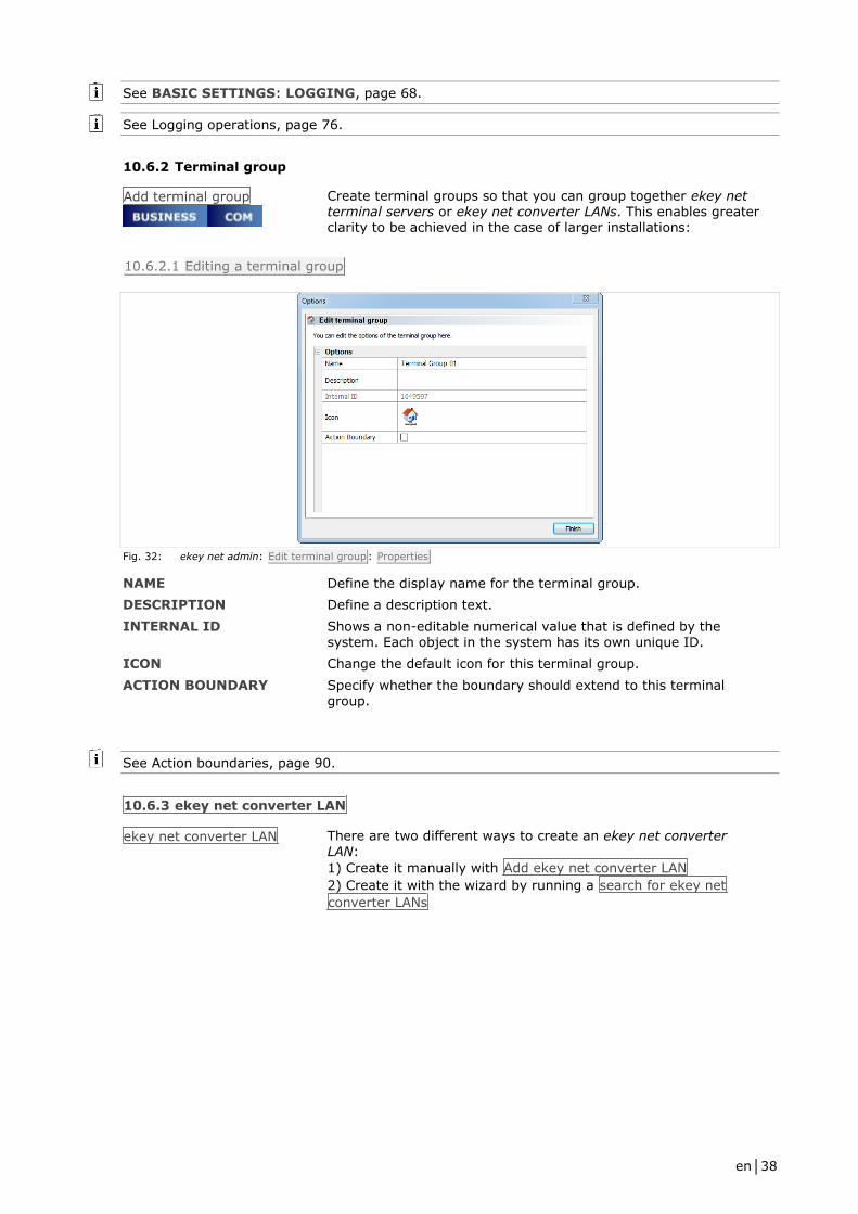
10.6.2 Terminal group
Add terminal group
Create terminal groups so that you can group together ekey net terminal servers or ekey net converter LANs. This enables greater clarity to be achieved in the case of larger installations:
10.6.2.1 Editing a terminal group
Fig. 32: ekey net admin: Edit terminal group: Properties
NAME Define the display name for the terminal group.
DESCRIPTION Define a description text.
INTERNAL ID Shows a non-editable numerical value that is defined by the system. Each object in the system has its own unique ID.
ICON Change the default icon for this terminal group.
ACTION BOUNDARY Specify whether the boundary should extend to this terminal group.
See Action boundaries, page 90.
10.6.3 ekey net converter LAN
ekey net converter LAN There are two different ways to create an ekey net converter
LAN:
1) Create it manually with Add ekey net converter LAN
2) Create it with the wizard by running a search for ekey net
converter LANs
en│39
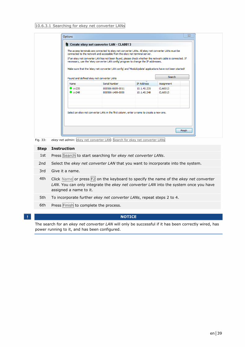
10.6.3.1 Searching for ekey net converter LANs
Fig. 33: ekey net admin: ekey net converter LAN: Search for ekey net converter LANs
Step Instruction
1st Press Search to start searching for ekey net converter LANs.
2nd Select the ekey net converter LAN that you want to incorporate into the system.
3rd Give it a name.
4th Click Name or press F2 on the keyboard to specify the name of the ekey net converter
LAN. You can only integrate the ekey net converter LAN into the system once you have
assigned a name to it.
5th To incorporate further ekey net converter LANs, repeat steps 2 to 4.
6th Press Finish to complete the process.
NOTICE
The search for an ekey net converter LAN will only be successful if it has been correctly wired, has
power running to it, and has been configured.
en│40
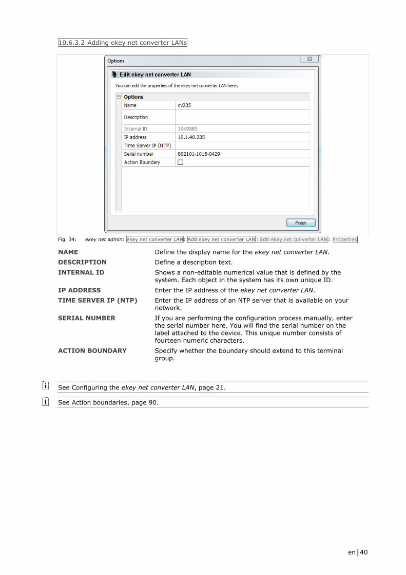
10.6.3.2 Adding ekey net converter LANs
Fig. 34: ekey net admin: ekey net converter LAN: Add ekey net converter LAN : Edit ekey net converter LAN: Properties
NAME Define the display name for the ekey net converter LAN.
DESCRIPTION Define a description text.
INTERNAL ID Shows a non-editable numerical value that is defined by the system. Each object in the system has its own unique ID.
IP ADDRESS Enter the IP address of the ekey net converter LAN.
TIME SERVER IP (NTP) Enter the IP address of an NTP server that is available on your network.
SERIAL NUMBER If you are performing the configuration process manually, enter the serial number here. You will find the serial number on the label attached to the device. This unique number consists of fourteen numeric characters.
ACTION BOUNDARY Specify whether the boundary should extend to this terminal group.
See Configuring the ekey net converter LAN, page 21.
See Action boundaries, page 90.

en│41
ATTENTION
All devices on the RS-485 bus get the current system time from the ekey net converter LAN. The
ekey net converter LAN is instructed to connect to the ekey net terminal server on a regular basis
so that it can synchronize its own system time.
If the ekey net converter LAN has not been able to establish a connection to the ekey net terminal
server for some time, the system time on the ekey net converter LAN may differ from the actual
time. This will impair the access functions.
Only users that have had the Always time zone assigned to them will definitely be able to gain
access. Specifying an NTP server on the ekey net converter LAN ensures that the time on the
devices will still be accurate even in an offline scenario (when there is no connection to the ekey
net terminal server). This means that access can take place offline without any restrictions,
provided that the ekey net converter LAN is able to reach the NTP server.
NOTICE
A device such as a finger scanner or a control panel cannot be located without a serial number.
Make sure that you have not made any typographical errors or transposed any digits while entering
the number.
10.6.4 Control panel
Control panel Specify a control panel by searching for it or entering the details manually.
NOTICE
You will only be able to locate a control panel successfully if it has been correctly wired and there is
power running to it.
10.6.4.1 Searching for a control panel
Fig. 35: ekey net admin: Control panel: Search for a control panel
en│42
NAME OF THE DEVICE Define the display name for the control panel.
DEVICE TYPE Specify whether this device is to be based on the default device
template or a customized one.
See Creating a customized device template, page 65.
Step Instruction
1st Assign a name to each of the devices found.
2nd If necessary, change the device type.
3rd Press Finish to complete the search process.
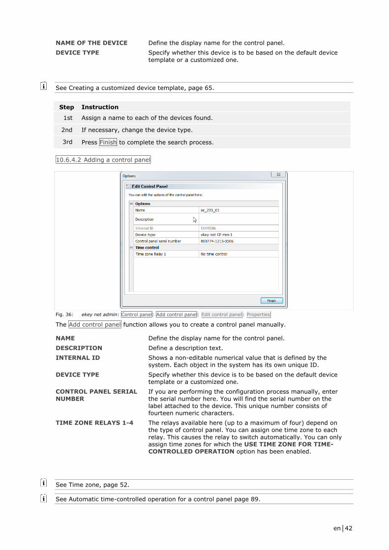
10.6.4.2 Adding a control panel
Fig. 36: ekey net admin: Control panel: Add control panel: Edit control panel : Properties
The Add control panel function allows you to create a control panel manually.
NAME Define the display name for the control panel.
DESCRIPTION Define a description text.
INTERNAL ID Shows a non-editable numerical value that is defined by the system. Each object in the system has its own unique ID.
DEVICE TYPE Specify whether this device is to be based on the default device template or a customized one.
CONTROL PANEL SERIAL
NUMBER
If you are performing the configuration process manually, enter
the serial number here. You will find the serial number on the label attached to the device. This unique number consists of fourteen numeric characters.
TIME ZONE RELAYS 1-4 The relays available here (up to a maximum of four) depend on the type of control panel. You can assign one time zone to each
relay. This causes the relay to switch automatically. You can only assign time zones for which the USE TIME ZONE FOR TIME-CONTROLLED OPERATION option has been enabled.
See Time zone, page 52.
See Automatic time-controlled operation for a control panel page 89.
en│43
NOTICE
A device such as a finger scanner or a control panel cannot be located without a serial number.
Make sure that you have not made any typographical errors or transposed any digits while entering
the number.
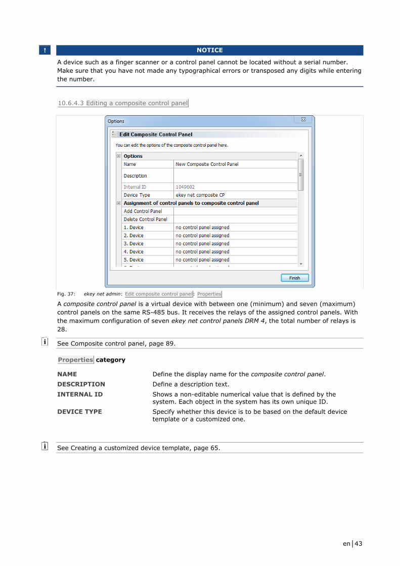
10.6.4.3 Editing a composite control panel
Fig. 37: ekey net admin: Edit composite control panel: Properties
A composite control panel is a virtual device with between one (minimum) and seven (maximum)
control panels on the same RS-485 bus. It receives the relays of the assigned control panels. With
the maximum configuration of seven ekey net control panels DRM 4, the total number of relays is
28.
See Composite control panel, page 89.
Properties category
NAME Define the display name for the composite control panel.
DESCRIPTION Define a description text.
INTERNAL ID Shows a non-editable numerical value that is defined by the system. Each object in the system has its own unique ID.
DEVICE TYPE Specify whether this device is to be based on the default device
template or a customized one.
See Creating a customized device template, page 65.
en│44
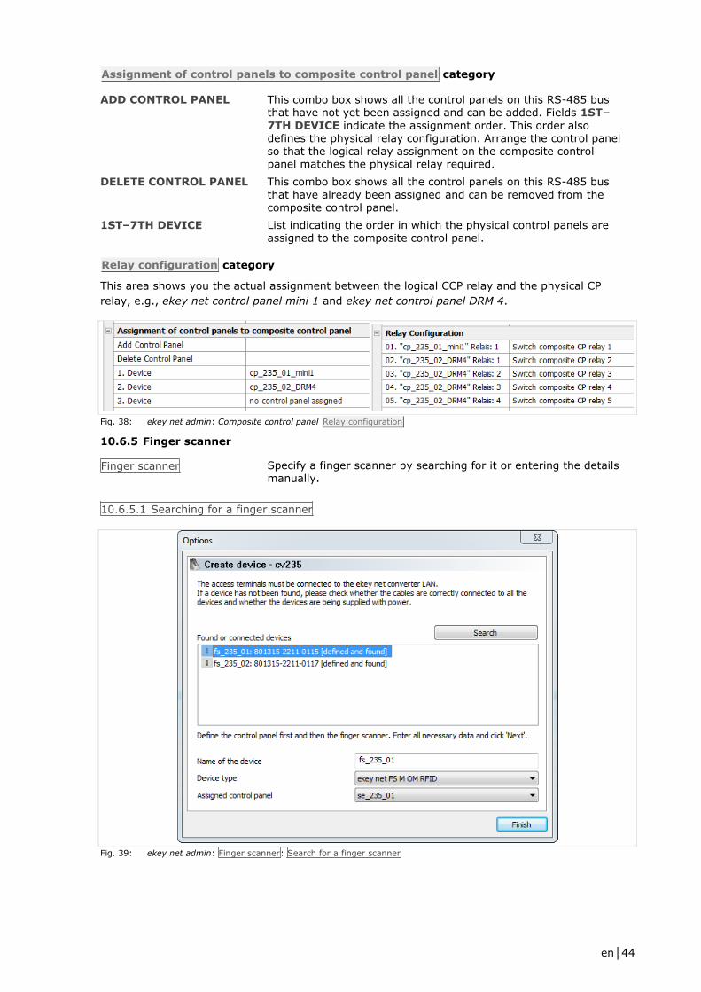
Assignment of control panels to composite control panel category
ADD CONTROL PANEL This combo box shows all the control panels on this RS-485 bus that have not yet been assigned and can be added. Fields 1ST–
7TH DEVICE indicate the assignment order. This order also defines the physical relay configuration. Arrange the control panel so that the logical relay assignment on the composite control panel matches the physical relay required.
DELETE CONTROL PANEL This combo box shows all the control panels on this RS-485 bus
that have already been assigned and can be removed from the composite control panel.
1ST–7TH DEVICE List indicating the order in which the physical control panels are assigned to the composite control panel.
Relay configuration category
This area shows you the actual assignment between the logical CCP relay and the physical CP
relay, e.g., ekey net control panel mini 1 and ekey net control panel DRM 4.
Fig. 38: ekey net admin: Composite control panel Relay configuration
10.6.5 Finger scanner
Finger scanner Specify a finger scanner by searching for it or entering the details manually.
10.6.5.1 Searching for a finger scanner
Fig. 39: ekey net admin: Finger scanner: Search for a finger scanner

en│45
NAME OF THE DEVICE Define the display name for the finger scanner.
DEVICE TYPE Specify whether this device is to be based on the default device
template or a customized one.
ASSIGNED CONTROL PANEL
Define which control panel is assigned to the finger scanner. This will then be switched by the finger scanner.
See Creating a customized device template, page 65.
ATTENTION
The control panels listed below the dividing line in this combo box are not located on the same RS-
485 bus as the finger scanner.
Any assignments that exceed the ekey net converter LAN or ekey net terminal server boundaries
will be subject to restrictions.
It is preferable to make all assignments on the same RS-485 bus.
Fig. 40: Select assigned control panel in combo box showing the boundary of the RS-485 bus
Step Instruction
1st Assign a name to each of the devices found.
2nd If necessary, change the device type.
3rd Assign a control panel to the finger scanner.
4th Press Finish to complete the search process.
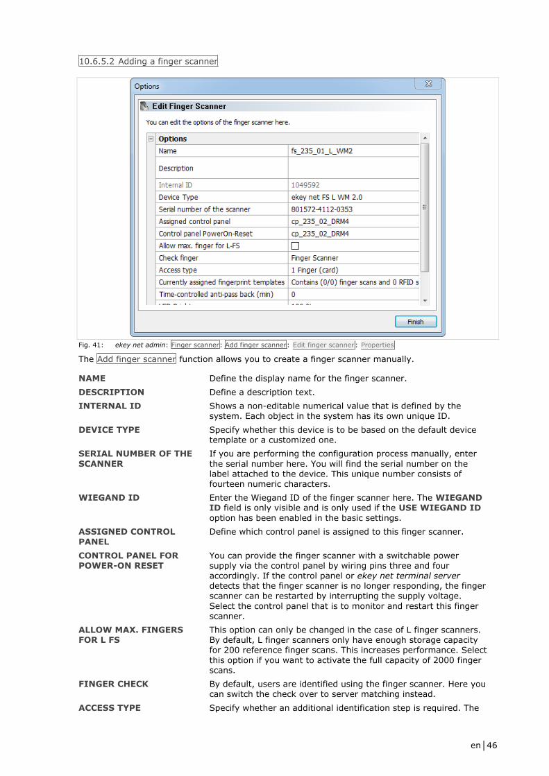
en│46
10.6.5.2 Adding a finger scanner
Fig. 41: ekey net admin: Finger scanner: Add finger scanner: Edit finger scanner : Properties
The Add finger scanner function allows you to create a finger scanner manually.
NAME Define the display name for the finger scanner.
DESCRIPTION Define a description text.
INTERNAL ID Shows a non-editable numerical value that is defined by the system. Each object in the system has its own unique ID.
DEVICE TYPE Specify whether this device is to be based on the default device template or a customized one.
SERIAL NUMBER OF THE
SCANNER
If you are performing the configuration process manually, enter
the serial number here. You will find the serial number on the label attached to the device. This unique number consists of fourteen numeric characters.
WIEGAND ID Enter the Wiegand ID of the finger scanner here. The WIEGAND ID field is only visible and is only used if the USE WIEGAND ID
option has been enabled in the basic settings.
ASSIGNED CONTROL
PANEL
Define which control panel is assigned to this finger scanner.
CONTROL PANEL FOR POWER-ON RESET
You can provide the finger scanner with a switchable power supply via the control panel by wiring pins three and four accordingly. If the control panel or ekey net terminal server detects that the finger scanner is no longer responding, the finger scanner can be restarted by interrupting the supply voltage.
Select the control panel that is to monitor and restart this finger scanner.
ALLOW MAX. FINGERS FOR L FS
This option can only be changed in the case of L finger scanners. By default, L finger scanners only have enough storage capacity for 200 reference finger scans. This increases performance. Select
this option if you want to activate the full capacity of 2000 finger scans.
FINGER CHECK By default, users are identified using the finger scanner. Here you can switch the check over to server matching instead.
ACCESS TYPE Specify whether an additional identification step is required. The

en│47
default setting is always 1 finger (card). The available values are
listed later on in this section.
RFID USE This option is only shown in the case of RFID finger scanners. Specify how RFID is to be used for this RFID finger scanner. The value defined for DEFAULT SETTING FOR USING RFID under Options is used by default.
CURRENTLY ASSIGNED FINGER SCANS
Shows the reference finger scans, RFID serial numbers, and how many users are currently assigned to this finger scanner.
TIME-CONTROLLED ANTI-
PASSBACK (MIN)
Once successfully identified via this finger scanner, a user is
blocked from gaining further access for the period of time defined here. Only once this time has expired is the user granted access
again. Permitted value range: 0–60 min. When set to 0, the
anti-passback function is disabled. 0 is the default setting.
LED BRIGHTNESS This option is only available for RS-485 finger scanners with an Authentec sensor. Define the brightness of the function LED. The
following values are possible: Off; 50%; 100%. 100% is the
default setting.
ENABLE FOR TIME
RECORDING
This option is disabled by default. Specify whether access
operations granted by this finger scanner should be recorded in the TIME RECORDING LOG.
WEB LOGGING This option is disabled by default. Specify whether events at this finger scanner should be used for web logging. All ekey net versions lower than 4 will have generated a web logging event for
each finger scanner. As a result, you can determine exactly which finger scanners require the use of web logging.
WEB LOGGING ACCOUNT This optional and freely definable value is assigned to Account.
You can, for example, use this field to create groups of several finger scanners for web logging operations.
ACCESS TYPE Description
1 finger (card) One user with one authorized finger or RFID transponder for triggering the event at the finger scanner. Default setting.
2 different users Two users, each with one authorized finger for the finger scanner. The event is triggered by the first finger swiped. The second finger (that of the second user) provides confirmation.
2 different fingers One user with two different authorized fingers. The event is
triggered by the first finger swiped. The second finger provides confirmation.
Table 8: ekey net admin: Finger scanner: Add finger scanner: Edit finger scanner : Properties : ACCESS TYPE
RFID USE Description
Use RFID only (no finger) The finger scanner makes exclusive use of RFID serial numbers for
the purpose of identifying users.
Use RFID + finger An RFID serial number and a registered user finger are both required for identification.
Use RFID or finger An RFID serial number or a registered user finger is required for identification.
Table 9: ekey net admin: Finger scanner: Add finger scanner: Edit finger scanner : Properties : RFID USE

en│48
See Creating a customized device template, page 65.
See BASIC SETTINGS – OPTIONS, page 58.
See Wiegand, page 95.
Cable the system in accordance with the supplied wiring diagram.
See Power-on reset special configuration, page 88.
See BASIC SETTINGS – OPTIONS, page 58.
See ekey net master server logging category, page 70.
See Configuring web logging operations, page 77.
NOTICE
A device such as a finger scanner or a control panel cannot be located without a serial number.
Make sure that you have not made any typographical errors or transposed any digits while entering
the number.
ATTENTION
You can assign a control panel on an external RS-485 bus to a finger scanner. The two RS-485
buses are either located on one ekey net terminal server or on different ekey net terminal servers.
The switching operations will only work if the ekey net terminal server is online – or if there are
several – if they are online and connected to one another.
NOTICE
If you assign a control panel to an ekey net FS REL, pay attention to the type of device assignment
that has been defined in the action for this finger scanner: local device or assigned device.
ATTENTION
ESD problems occasionally occur.
If you are unable to contain these (e.g., if earthing is not possible, shag pile floor covering, etc.),
the control panel on the same RS-485 bus may no longer be capable of performing a shutdown.
To accommodate this rare situation, there is a special ESD configuration involving additional
hardware.
NOTICE
If you enable ALLOW MAX. FINGERS FOR L FS, the FINGER CHECK option also switches over
from Finger scanner to Server.
ATTENTION
Never use more than 200 finger scans on one finger scanner without enabling server matching.
Otherwise, you will increase the risk of a false acceptance.
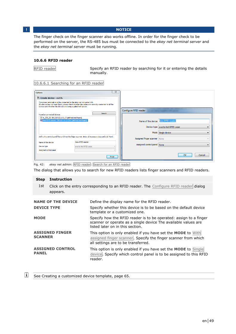
en│49
NOTICE
The finger check on the finger scanner also works offline. In order for the finger check to be
performed on the server, the RS-485 bus must be connected to the ekey net terminal server and
the ekey net terminal server must be running.
10.6.6 RFID reader
RFID reader Specify an RFID reader by searching for it or entering the details manually.
10.6.6.1 Searching for an RFID reader
Fig. 42: ekey net admin: RFID reader: Search for an RFID reader
The dialog that allows you to search for new RFID readers lists finger scanners and RFID readers.
Step Instruction
1st Click on the entry corresponding to an RFID reader. The Configure RFID reader dialog
appears.
NAME OF THE DEVICE Define the display name for the RFID reader.
DEVICE TYPE Specify whether this device is to be based on the default device template or a customized one.
MODE Specify how the RFID reader is to be operated: assign to a finger scanner or operate as a single device The available values are listed later on in this section.
ASSIGNED FINGER
SCANNER This option is only enabled if you have set the MODE to With
assigned finger scanner. Specify the finger scanner from which
all settings are to be transferred.
ASSIGNED CONTROL PANEL
This option is only enabled if you have set the MODE to Single
device. Specify which control panel is to be assigned to this RFID
reader.
See Creating a customized device template, page 65.
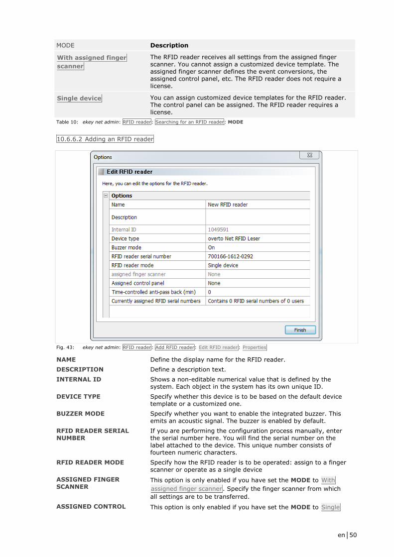
en│50
MODE Description
With assigned finger
scanner
The RFID reader receives all settings from the assigned finger scanner. You cannot assign a customized device template. The assigned finger scanner defines the event conversions, the assigned control panel, etc. The RFID reader does not require a license.
Single device You can assign customized device templates for the RFID reader. The control panel can be assigned. The RFID reader requires a
license.
Table 10: ekey net admin: RFID reader: Searching for an RFID reader: MODE
10.6.6.2 Adding an RFID reader
Fig. 43: ekey net admin: RFID reader: Add RFID reader: Edit RFID reader : Properties
NAME Define the display name for the RFID reader.
DESCRIPTION Define a description text.
INTERNAL ID Shows a non-editable numerical value that is defined by the system. Each object in the system has its own unique ID.
DEVICE TYPE Specify whether this device is to be based on the default device template or a customized one.
BUZZER MODE Specify whether you want to enable the integrated buzzer. This emits an acoustic signal. The buzzer is enabled by default.
RFID READER SERIAL NUMBER
If you are performing the configuration process manually, enter the serial number here. You will find the serial number on the label attached to the device. This unique number consists of fourteen numeric characters.
RFID READER MODE Specify how the RFID reader is to be operated: assign to a finger scanner or operate as a single device
ASSIGNED FINGER SCANNER
This option is only enabled if you have set the MODE to With
assigned finger scanner. Specify the finger scanner from which
all settings are to be transferred.
ASSIGNED CONTROL This option is only enabled if you have set the MODE to Single

en│51
PANEL device. Specify which control panel is to be assigned to this RFID
reader.
TIME-CONTROLLED ANTI-PASSBACK (MIN)
Once successfully identified via this finger scanner, a user is blocked from gaining further access for the period of time defined here. Only once this time has expired is the user granted access
again. Permitted value range: 0–60 min. When set to 0, the
anti-passback function is disabled. 0 is the default setting.
CURRENTLY ASSIGNED RFID IDS
Shows which RFID serial numbers and how many users are currently assigned to this RFID reader.
ENABLE FOR TIME RECORDING
This option is disabled by default. Specify whether access operations granted by this finger scanner should be recorded in the TIME RECORDING LOG.
WEB LOGGING This option is disabled by default. Specify whether events at this RFID reader should be used for web logging.
WEB LOGGING ACCOUNT This optional and freely definable value is assigned to Account.
You can, for example, use this field to create groups of several RFID readers for web logging operations.
See Creating a customized device template, page 65.
See ekey net master server logging category, page 70.
See Configuring web logging operations, page 77.
NOTICE
A device such as a finger scanner or a control panel cannot be located without a serial number.
Make sure that you have not made any typographical errors or transposed any digits while entering
the number.
ATTENTION
The control panels listed below the dividing line in this combo box are not located on the same RS-
485 bus as the finger scanner.
Any assignments that exceed the ekey net converter LAN or ekey net terminal server boundaries
will be subject to restrictions.
It is preferable to make all assignments on the same RS-485 bus.
ATTENTION
You can assign a control panel on an external RS-485 bus to a finger scanner. The two RS-485
buses are either located on one ekey net terminal server or on different ekey net terminal servers.
The switching operations will only work if the ekey net terminal server is online – or if there are
several – if they are online and connected to one another.
NOTICE
If you assign a control panel to an ekey net FS REL, pay attention to the type of device assignment
that has been defined in the action for this finger scanner: local device or assigned device.
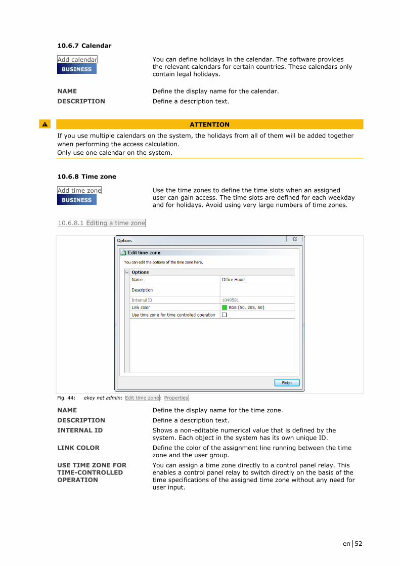
en│52
10.6.7 Calendar
Add calendar
You can define holidays in the calendar. The software provides the relevant calendars for certain countries. These calendars only contain legal holidays.
NAME Define the display name for the calendar.
DESCRIPTION Define a description text.
ATTENTION
If you use multiple calendars on the system, the holidays from all of them will be added together
when performing the access calculation.
Only use one calendar on the system.
10.6.8 Time zone
Add time zone
Use the time zones to define the time slots when an assigned user can gain access. The time slots are defined for each weekday and for holidays. Avoid using very large numbers of time zones.
10.6.8.1 Editing a time zone
Fig. 44: ekey net admin: Edit time zone: Properties
NAME Define the display name for the time zone.
DESCRIPTION Define a description text.
INTERNAL ID Shows a non-editable numerical value that is defined by the
system. Each object in the system has its own unique ID.
LINK COLOR Define the color of the assignment line running between the time zone and the user group.
USE TIME ZONE FOR TIME-CONTROLLED OPERATION
You can assign a time zone directly to a control panel relay. This enables a control panel relay to switch directly on the basis of the time specifications of the assigned time zone without any need for user input.

en│53
ATTENTION
It is not just in conjunction with the control panel that time zones for time-controlled operation
may be used. They are not visible in the Authorizations view.
If a normal time zone is converted into one for time-controlled operation, all the assigned access
authorizations will be lost.
10.6.8.2 Defining time slots
You can define the time slots for weekdays, holidays, and the keep-switched function on the Times
tab. Please note the following:
□ Each time zone is made up of multiple time slots
□ A time slot defines the start and end times
□ Unless a time zone contains at least one time slot, no access will be granted
□ The minimum length for each time slot is one minute
Step Instruction
1st Drag a time slot with the mouse.
2nd Click on the time slot.
3rd Use the From and Until input fields to define the times.
Fig. 45: ekey net admin: Edit time zone: Time slots
1 Selected time slot: Start time
2 Selected time slot: End time
3 Check box for enabling/disabling the keep-switched function
4 Deletes the selected time slot or, if none have been selected, all of them 5 Fills all time bars with the period 00:00 to 24:00
6 Copies a time slot into the required days
7 Undo function
8 Applies the changes
Fig. 46: ekey net admin: Edit time zone: Time slots: Color legend
1 Time zone without keep-switched function
2 Selected time zone without keep-switched function
3 Time zone with keep-switched function
4 Selected time zone with keep-switched function
10.6.8.3 Time zone keep-switched function
You can keep a relay continuously open for a definable period. It is switched on as soon as an
authorized user with an authorized finger or RFID transponder gains access.

en│54
ATTENTION
Some locks are not suitable for continuous opening.
A constant power supply would damage the locking system.
If you want to use the keep-switched function, you must check whether your locking system (door
strike, motorized lock, etc.) is suitable for continuous opening.
If you have selected the keep-switched function and swipe an authorized finger over the finger
scanner, the associated relay switches permanently. The keep-switched function will switch itself
off in response to either of the following events:
□ If the defined time slot has expired
□ If an action that relies on the Off SWITCHING MODE occurs, e.g., the Relay 1 off action
ATTENTION
If you have defined a time slot that ends at 24:00 and another one is due to begin the next day at
00:00, the relay will drop out when the time slot for the next day finishes instead of dropping out
at 24:00. E.g.: Monday 21:00–24:00 and Tuesday 00:00–09:00, switch-on time: Monday 21:00,
switch-off time: Tuesday 09:00
Time slots are only allowed to span midnight once without a break. E.g.: Start Monday 12:30 and
run until Wednesday 2:00. The relay drops out at 24:00 on Tuesday.
ATTENTION
If you:
□ change a time zone time slot that includes the keep-switched function,
□ only use Send changes to devices to activate these changes,
□ and the old end time comes after the new end time,
the keep-switched function may not switch off at the end time, leaving the door open.
In order for the new keep-switched function end time to be applied, you must swipe an authorized
finger once at all the doors for which the keep-switched function is enabled.
ATTENTION
If you delete a time zone time slot that includes the keep-switched function and only use Send
changes to devices to activate these changes, the keep-switched function may not switch off at the
end time, leaving the door open.
You must switch the relay off manually for all the doors that have the keep-switched function
enabled or wait until the end time for the keep-switched function is reached.
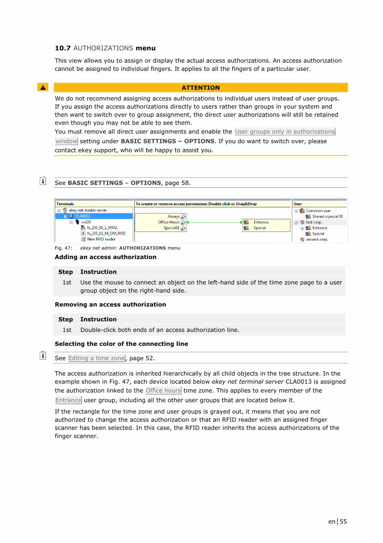
en│55
10.7 AUTHORIZATIONS menu
This view allows you to assign or display the actual access authorizations. An access authorization
cannot be assigned to individual fingers. It applies to all the fingers of a particular user.
ATTENTION
We do not recommend assigning access authorizations to individual users instead of user groups.
If you assign the access authorizations directly to users rather than groups in your system and
then want to switch over to group assignment, the direct user authorizations will still be retained
even though you may not be able to see them.
You must remove all direct user assignments and enable the User groups only in authorizations
window setting under BASIC SETTINGS – OPTIONS. If you do want to switch over, please
contact ekey support, who will be happy to assist you.
See BASIC SETTINGS – OPTIONS, page 58.
Fig. 47: ekey net admin: AUTHORIZATIONS menu
Adding an access authorization
Step Instruction
1st Use the mouse to connect an object on the left-hand side of the time zone page to a user
group object on the right-hand side.
Removing an access authorization
Step Instruction
1st Double-click both ends of an access authorization line.
Selecting the color of the connecting line
See Editing a time zone, page 52.
The access authorization is inherited hierarchically by all child objects in the tree structure. In the
example shown in Fig. 47, each device located below ekey net terminal server CLA0013 is assigned
the authorization linked to the Office hours time zone. This applies to every member of the
Entrance user group, including all the other user groups that are located below it.
If the rectangle for the time zone and user groups is grayed out, it means that you are not
authorized to change the access authorization or that an RFID reader with an assigned finger
scanner has been selected. In this case, the RFID reader inherits the access authorizations of the
finger scanner.

en│56
ATTENTION
If multiple times zones are assigned to a user group or to a single user on each finger scanner, this
results in undefined behavior for the user.
The system is not capable of deciding which time zone to use.
In this case, the system will use the time zone with the lowest internal ID to determine whether
access is permitted.
10.8 STATUS menu
This view shows the status of all the devices in the system.
Fig. 48: ekey net admin: STATUS menu
The list of devices and log view will vary according to which device is selected.
Fig. 49: ekey net admin: STATUS: Device status
Status All devices associated with the ekey net master server and ekey
net terminal servers are shown in the Status column. If the
devices feature relays (ekey net FS REL and ekey net CP), the relays are shown as LEDs on the right. If a color has been applied to highlight a device, it means there is a problem. The switching statuses of the relays are indicated in color.
Name Name of the device.
Last action Time when the last action was performed on device.
Version Firmware version of the device or file version of the ekey net terminal server or ekey net master server. If 0.0.0.0 is shown, it
means the version is unknown.
User Number of users with reference finger scans/an RFID serial number currently stored on this finger scanner. This is only shown in the case of finger scanners.
Fingers Number of reference finger scans currently stored on this finger scanner and the maximum permissible number of reference finger scans that can be stored (dependent on finger scanner type: S, M, or L). This is only shown in the case of finger scanners.
Inputs Shows the status of the digital inputs on devices with one or more digital inputs. The inputs are shown as LEDs.

en│57
Color Description
Device - red The device is offline.
Device - yellow The device is not ready for operation. You must perform an action manually on the device, e.g., trigger a restart by pressing the button on the control panel.
Device - gray The device is online. The device firmware is out of date and must be updated.
Device - no color The device is online.
Relay - gray Relay status = not switched.
Relay - green Relay status = switched.
Relay - yellow Relay status = unknown.
Input - gray Input status = off.
Input - green Input status = on.
Input - yellow Input status = unknown.
Table 11: Device status : Color codes
ATTENTION
If a device is highlighted in gray, you must update its firmware as a matter of urgency.
Until you update the firmware, there is no assurance that it will operate properly.
Update the device firmware.

en│58
10.9 BASIC SETTINGS menu
10.9.1 BASIC SETTINGS – OPTIONS
USER GROUPS ONLY IN AUTHORIZATIONS WINDOW
This option is enabled by default in the case of new installations. When this option is enabled, you can only assign an access authorization to a user group and not to an individual user.
USE WIEGAND ID
This option activates Wiegand support and makes the Wiegand
ID field available under the user and finger scanner properties. It
is disabled by default.
USE PKE
This option activates support for the PKE access control system. It requires special ekey net FS, the PKE net FS, and an access
control system from PKE.
STANDARD SYMBOL USED FOR TERMINAL
GROUPS
If you add a new terminal group, this symbol is assigned to it. Regardless of the setting made here, you can still change the
symbol under the properties for the terminal group.
ONLY ALLOW RELIABLE FINGERS FOR ENROLLMENT
The thumb and little finger are only suitable for creating reference finger scans to a limited extent. Therefore, these fingers are locked by default in the finger selection area.
SWITCHING TIME FOR
RELAYS 1 TO 4
Individually define the default relay impulse switching time in
milliseconds. The default setting for all four relays is 3,000 ms. Minimum value: 500 ms Maximum value: 60,000 ms Increment: 100 ms
RFID READER Define which RFID reader you want to use for the purpose of
assigning RFID serial numbers to users. The default setting is Do
not use or not available.
DEFAULT SETTING FOR USING RFID
Define how each newly integrated finger scanner featuring the RFID function should use RFID serial numbers and reference
finger scans for authorizing access. The default setting is Use
RFID or finger.
RFID READER Description
Finger scanner with RFID
function
A finger scanner featuring the RFID function is used to detect the RFID serial number.
TRH-SR-100 The TRH-SR-100 RFID reader is used to detect the RFID serial number.
RFID reader with
keyboard emulator
function
A USB RFID reader with special drivers is used to detect the RFID serial number.
Table 12: ekey net admin: BASIC SETTINGS menu: OPTIONS: RFID: RFID READER
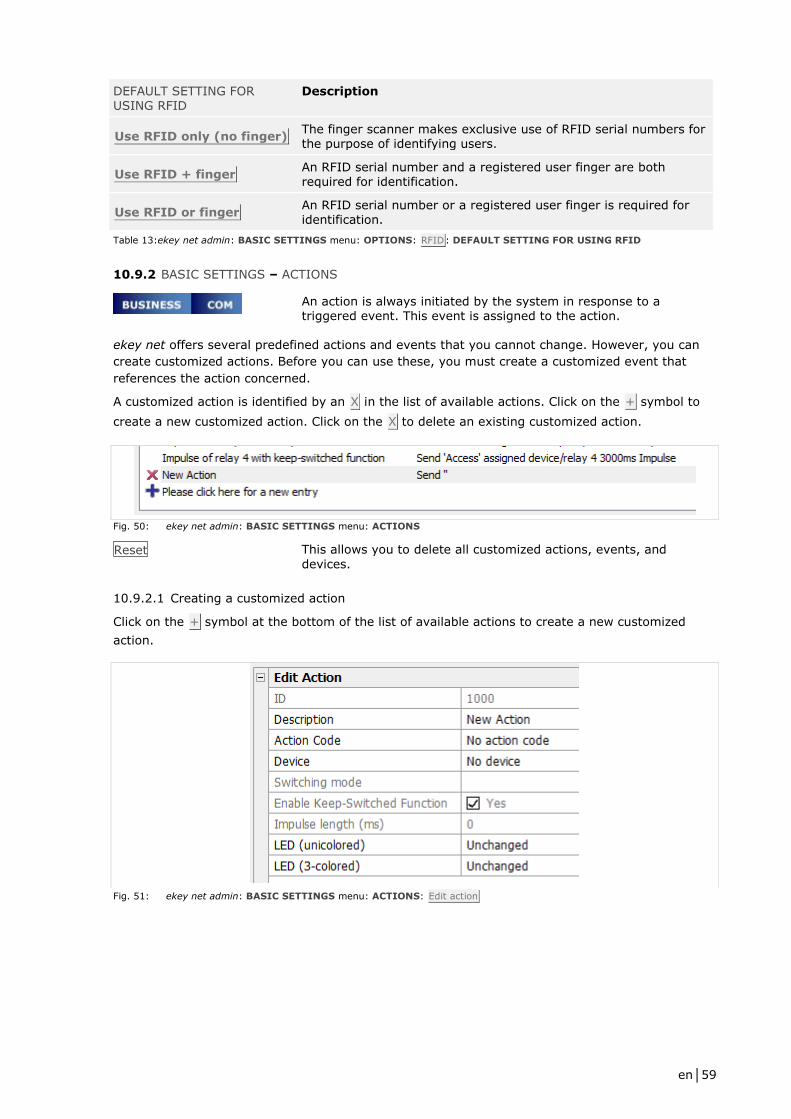
en│59
DEFAULT SETTING FOR USING RFID
Description
Use RFID only (no finger) The finger scanner makes exclusive use of RFID serial numbers for the purpose of identifying users.
Use RFID + finger An RFID serial number and a registered user finger are both required for identification.
Use RFID or finger An RFID serial number or a registered user finger is required for identification.
Table 13:ekey net admin: BASIC SETTINGS menu: OPTIONS: RFID: DEFAULT SETTING FOR USING RFID
10.9.2 BASIC SETTINGS – ACTIONS
An action is always initiated by the system in response to a triggered event. This event is assigned to the action.
ekey net offers several predefined actions and events that you cannot change. However, you can
create customized actions. Before you can use these, you must create a customized event that
references the action concerned.
A customized action is identified by an X in the list of available actions. Click on the + symbol to
create a new customized action. Click on the X to delete an existing customized action.
Fig. 50: ekey net admin: BASIC SETTINGS menu: ACTIONS
Reset This allows you to delete all customized actions, events, and
devices.
10.9.2.1 Creating a customized action
Click on the + symbol at the bottom of the list of available actions to create a new customized
action.
Fig. 51: ekey net admin: BASIC SETTINGS menu: ACTIONS: Edit action
en│60
DESCRIPTION Define a description text.
ACTION CODE The action code is used for logging purposes. The system will not
create a log entry unless you have defined a code.
DEVICE Specify which relay is to perform the action on which device.
SWITCHING MODE Specify how the relay is to be controlled. If you have selected No
device, this button is disabled.
ENABLE KEEP-SWITCHED
FUNCTION
Specify here whether the keep-switched function should be used.
The main difference compared with the ON or Impulse
SWITCHING MODE is that switch-off is performed in accordance
with the time zone settings. If you have selected No device, this
button is disabled.
IMPULSE LENGTH Define the default impulse switching time for the action in
milliseconds. The default setting is 3,000 ms. If No device has
been specified or if Impulse has not been set for the switching
mode, this button is disabled. Minimum value: 500 ms Maximum value: 60,000 ms Increment: 100 ms
LED (UNICOLORED) For Atmel sensors. Specify whether the right-hand status LED should be controlled differently with the ekey net FS WM.
LED (3-COLORED) For Authentec sensors. Specify whether the right-hand status LED should be controlled differently with the ekey net FS IN.
See Control for the ekey bit/ekey net finger scanner, page 8.
ACTION CODE Description
No action code The action does not generate a log entry.
Access Identification successful, the user has the necessary access authorization.
Exit Identification successful, the user has the necessary access authorization.
Refused Identification successful, but the user does not currently have the necessary access authorization (not granted by time zone, calendar, or validity period).
Unrecognized finger Identification unsuccessful.
Intrusion alarm system
on Activates the intrusion alarm system.
Intrusion alarm system
off Deactivates the intrusion alarm system.
Restart device The finger scanner is restarted.
Switch Changes the switching status from ON to OFF, or vice versa.
Table 14: ekey net admin: BASIC SETTINGS menu: ACTIONS: Edit action: ACTION CODE
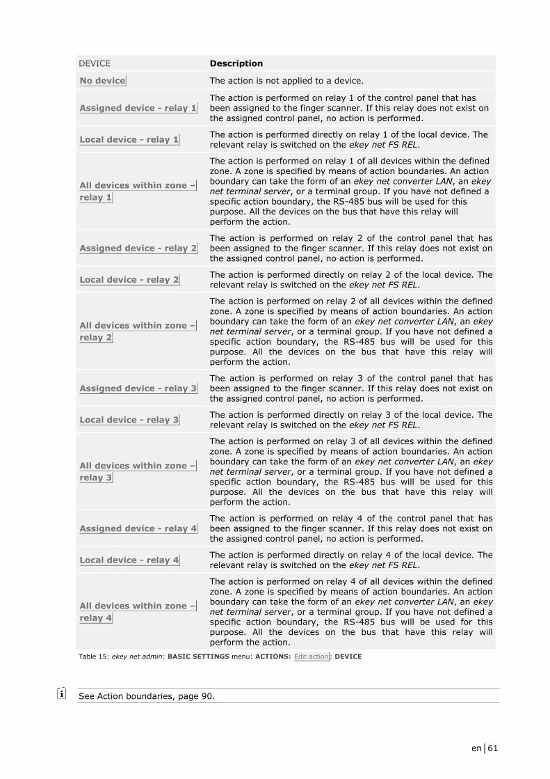
en│61
DEVICE Description
No device The action is not applied to a device.
Assigned device - relay 1 The action is performed on relay 1 of the control panel that has been assigned to the finger scanner. If this relay does not exist on
the assigned control panel, no action is performed.
Local device - relay 1 The action is performed directly on relay 1 of the local device. The relevant relay is switched on the ekey net FS REL.
All devices within zone –
relay 1
The action is performed on relay 1 of all devices within the defined zone. A zone is specified by means of action boundaries. An action boundary can take the form of an ekey net converter LAN, an ekey net terminal server, or a terminal group. If you have not defined a specific action boundary, the RS-485 bus will be used for this purpose. All the devices on the bus that have this relay will
perform the action.
Assigned device - relay 2 The action is performed on relay 2 of the control panel that has been assigned to the finger scanner. If this relay does not exist on the assigned control panel, no action is performed.
Local device - relay 2 The action is performed directly on relay 2 of the local device. The relevant relay is switched on the ekey net FS REL.
All devices within zone –
relay 2
The action is performed on relay 2 of all devices within the defined zone. A zone is specified by means of action boundaries. An action boundary can take the form of an ekey net converter LAN, an ekey net terminal server, or a terminal group. If you have not defined a
specific action boundary, the RS-485 bus will be used for this purpose. All the devices on the bus that have this relay will perform the action.
Assigned device - relay 3
The action is performed on relay 3 of the control panel that has
been assigned to the finger scanner. If this relay does not exist on the assigned control panel, no action is performed.
Local device - relay 3 The action is performed directly on relay 3 of the local device. The relevant relay is switched on the ekey net FS REL.
All devices within zone –
relay 3
The action is performed on relay 3 of all devices within the defined zone. A zone is specified by means of action boundaries. An action
boundary can take the form of an ekey net converter LAN, an ekey net terminal server, or a terminal group. If you have not defined a specific action boundary, the RS-485 bus will be used for this purpose. All the devices on the bus that have this relay will perform the action.
Assigned device - relay 4 The action is performed on relay 4 of the control panel that has been assigned to the finger scanner. If this relay does not exist on the assigned control panel, no action is performed.
Local device - relay 4 The action is performed directly on relay 4 of the local device. The
relevant relay is switched on the ekey net FS REL.
All devices within zone –
relay 4
The action is performed on relay 4 of all devices within the defined zone. A zone is specified by means of action boundaries. An action boundary can take the form of an ekey net converter LAN, an ekey net terminal server, or a terminal group. If you have not defined a specific action boundary, the RS-485 bus will be used for this purpose. All the devices on the bus that have this relay will
perform the action.
Table 15: ekey net admin: BASIC SETTINGS menu: ACTIONS: Edit action : DEVICE
See Action boundaries, page 90.
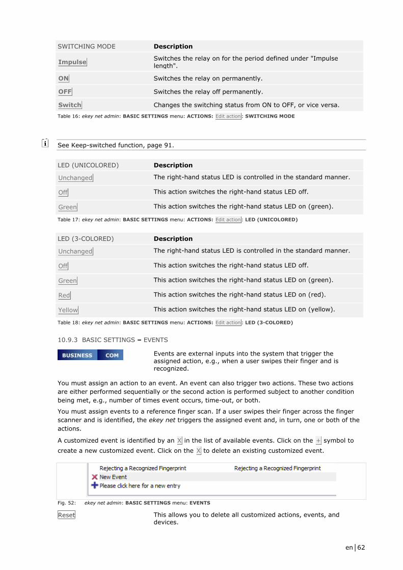
en│62
SWITCHING MODE Description
Impulse Switches the relay on for the period defined under "Impulse length".
ON Switches the relay on permanently.
OFF Switches the relay off permanently.
Switch Changes the switching status from ON to OFF, or vice versa.
Table 16: ekey net admin: BASIC SETTINGS menu: ACTIONS: Edit action : SWITCHING MODE
See Keep-switched function, page 91.
LED (UNICOLORED) Description
Unchanged The right-hand status LED is controlled in the standard manner.
Off This action switches the right-hand status LED off.
Green This action switches the right-hand status LED on (green).
Table 17: ekey net admin: BASIC SETTINGS menu: ACTIONS: Edit action : LED (UNICOLORED)
LED (3-COLORED) Description
Unchanged The right-hand status LED is controlled in the standard manner.
Off This action switches the right-hand status LED off.
Green This action switches the right-hand status LED on (green).
Red This action switches the right-hand status LED on (red).
Yellow This action switches the right-hand status LED on (yellow).
Table 18: ekey net admin: BASIC SETTINGS menu: ACTIONS: Edit action : LED (3-COLORED)
10.9.3 BASIC SETTINGS – EVENTS
Events are external inputs into the system that trigger the assigned action, e.g., when a user swipes their finger and is
recognized.
You must assign an action to an event. An event can also trigger two actions. These two actions
are either performed sequentially or the second action is performed subject to another condition
being met, e.g., number of times event occurs, time-out, or both.
You must assign events to a reference finger scan. If a user swipes their finger across the finger
scanner and is identified, the ekey net triggers the assigned event and, in turn, one or both of the
actions.
A customized event is identified by an X in the list of available events. Click on the + symbol to
create a new customized event. Click on the X to delete an existing customized event.
Fig. 52: ekey net admin: BASIC SETTINGS menu: EVENTS
Reset This allows you to delete all customized actions, events, and devices.

en│63
10.9.3.1 Creating a customized event
Click on the + symbol at the bottom of the list of available events to create a new customized
event.
Fig. 53: ekey net admin: BASIC SETTINGS menu: EVENTS: Edit event
DESCRIPTION Define a description text.
ACTION From the dropdown menu, select the primary action that is to be triggered if this event occurs. If you require a second action
(ACTION WHEN COUNTER ENDS) for this event, use the following three optional settings to specify whether the second action should be triggered subject to certain conditions or always: COUNTER, RESET, and TIMEOUT IN SECONDS. If you do not apply any of the three settings, the second action will always be performed.
COUNTER Specify how many times this event must occur in order for the action defined under ACTION WHEN COUNTER ENDS to be
triggered. Value range: 1–100. If you specify 1 or 0, the action
defined under ACTION will be triggered first and then the one defined under ACTION WHEN COUNTER ENDS.
RESET Specify what condition must be met in order for the counter to be reset.
TIMEOUT IN SECONDS This field is only enabled if you have selected Timeout or By an
event or timeout under RESET. Value range: 1–3,600 s.
ACTION WHEN COUNTER ENDS
Optional second action that is controlled by the COUNTER, RESET, and TIMEOUT IN SECONDS conditions. Select the appropriate action from the dropdown menu.
EVENT CODE Optional text that you can freely define. Maximum length is 15 characters. This field is sent to external programs by the ekey net terminal server using UDP transmission.
See Creating a customized action, page 59.
RESET Description
Never The counter is reset automatically when the defined value is reached.
By a different event The counter is reset if an event of any other kind occurs.
Timeout The event must be triggered repeatedly for the number of times set under COUNTER in order for the action defined under ACTION WHEN COUNTER ENDS to be triggered. However, if this number is not reached within the specified period, the counter is reset.
By an event or timeout Both methods combined.
Table 19: ekey net admin: BASIC SETTINGS menu: EVENTS: Edit customized event : RESET

en│64
NOTICE
You are not allowed to use any actions that affect a zone, even though they can be assigned. The
action is performed locally or not at all.
10.9.4 BASIC SETTINGS – DEVICES
Devices are finger scanners, control panels, and the ekey net converter Wiegand (i.e., the special control panel) connected to the RS-485 bus.
Every device that you incorporate into the system, receives its specific properties from the
assigned device type. Whenever you incorporate a new device into the system, the predefined
device type is always used by default.
You cannot change the device templates that have been predefined by ekey. If you want to change
the properties of a device, create a customized device template and assign it to the specific device
concerned.
The following devices may not be available, depending on the license type:
Device
All control panels Available Not available Available
ekey net CV WIEG Not available Available Available
PKE net L FS OM Verify Not available Available Not available
PKE net M FS OM Identify Not available Available Not available
All remaining finger scanners
Available
L finger scanners are only available with a restricted finger scan
capacity of 200.
Available Available
Table 20: Devices available in ekey net according to license type
A customized device template is identified by an X in the list of available device templates. Click on
the + symbol to create a new customized device template. Click on the X to delete an existing
customized device template.
Fig. 54: ekey net admin: BASIC SETTINGS menu: DEVICES
Reset This allows you to delete all customized actions, events, and devices.
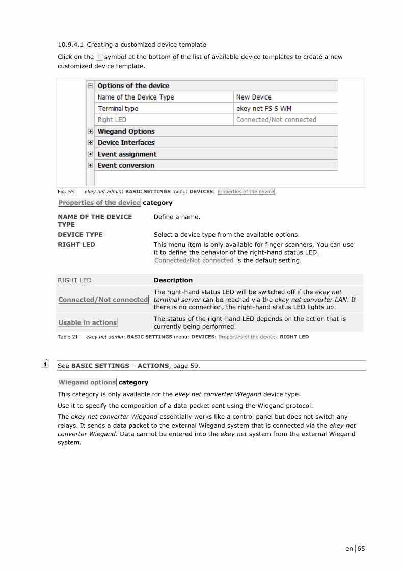
en│65
10.9.4.1 Creating a customized device template
Click on the + symbol at the bottom of the list of available device templates to create a new
customized device template.
Fig. 55: ekey net admin: BASIC SETTINGS menu: DEVICES: Properties of the device
Properties of the device category
NAME OF THE DEVICE
TYPE
Define a name.
DEVICE TYPE Select a device type from the available options.
RIGHT LED This menu item is only available for finger scanners. You can use it to define the behavior of the right-hand status LED.
Connected/Not connected is the default setting.
RIGHT LED Description
Connected/Not connected The right-hand status LED will be switched off if the ekey net
terminal server can be reached via the ekey net converter LAN. If there is no connection, the right-hand status LED lights up.
Usable in actions The status of the right-hand LED depends on the action that is currently being performed.
Table 21: ekey net admin: BASIC SETTINGS menu: DEVICES: Properties of the device: RIGHT LED
See BASIC SETTINGS – ACTIONS, page 59.
Wiegand options category
This category is only available for the ekey net converter Wiegand device type.
Use it to specify the composition of a data packet sent using the Wiegand protocol.
The ekey net converter Wiegand essentially works like a control panel but does not switch any
relays. It sends a data packet to the external Wiegand system that is connected via the ekey net
converter Wiegand. Data cannot be entered into the ekey net system from the external Wiegand
system.

en│66
PROTOCOL Wiegand protocols are available in various versions, which differ in terms of their data content and bit length.
TOTAL BIT LENGTH The value is calculated from the other values. You cannot define it directly.
OEM BIT LENGTH Length of the OEM identifier in bits. Value range: 0–8 bits.
FINGER SCANNER ID BIT LENGTH
Length of the finger scanner ID in bits. Value range: 8–64 bits.
USER ID BIT LENGTH Value range: 16–64 bits.
OEM IDENTIFIER Identifier for a particular company. This is used to distinguish between the individual companies in the case of cross-company installations. The value range is dependent on the OEM bit length.
PROTOCOL Total bit length
OEM bit length
Finger scanner ID bit length
User ID bit length
OEM identifier
Standard 26 0 8 16 0
Pyramid 39 0 17 20 0
Customized All values are freely selectable within the defined limits.
Table 22: ekey net admin: BASIC SETTINGS menu: DEVICES: Wiegand options: PROTOCOL
Device interfaces category
This category is only available for control panels and finger scanners with relays and/or a status
input.
Define the following here:
□ Assignment between interfaces and input/output
□ Names of relays and inputs
Event assignment category
This category is only available for finger scanners.
Specify here which event is to be triggered in the following scenarios:
□ If finger is not recognized
□ If finger is recognized but it is rejected on the basis of a particular time or calendar
restriction
The following are set by default:
□ EVENT FOR REFUSING UNRECOGNIZED FINGER: Refuse unrecognized finger
□ EVENT FOR REFUSING RECOGNIZED FINGER: Refuse recognized finger
Event conversion category
This category is only available for finger scanners.
Use this area to specify that an event assigned to a recognized finger should not be performed. The
event that you define here will be performed instead. In this way, you can trigger different events
on various finger scanners with just one reference finger scan.
10.9.5 BASIC SETTINGS – RIGHTS
Here, you can convert existing user accounts into administrator accounts, delete administrator
accounts, edit an administrator account, or generate web access keys for an administrator account.
Add Assigns administrator rights to a normal user account.
Delete Removes the administrator rights from a user account.
New keys Creates a set of single-use keys for web access under a particular administrator account.
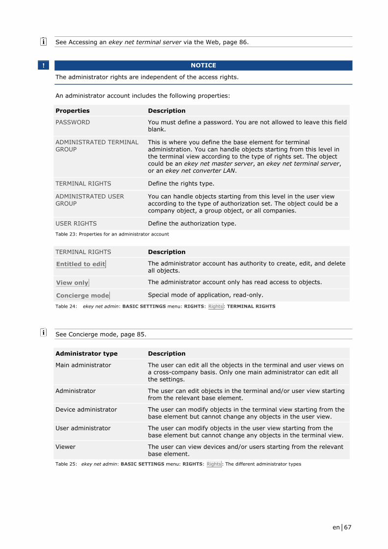
en│67
See Accessing an ekey net terminal server via the Web, page 86.
NOTICE
The administrator rights are independent of the access rights.
An administrator account includes the following properties:
Properties Description
PASSWORD You must define a password. You are not allowed to leave this field blank.
ADMINISTRATED TERMINAL GROUP
This is where you define the base element for terminal administration. You can handle objects starting from this level in the terminal view according to the type of rights set. The object
could be an ekey net master server, an ekey net terminal server, or an ekey net converter LAN.
TERMINAL RIGHTS Define the rights type.
ADMINISTRATED USER GROUP
You can handle objects starting from this level in the user view according to the type of authorization set. The object could be a company object, a group object, or all companies.
USER RIGHTS Define the authorization type.
Table 23: Properties for an administrator account
TERMINAL RIGHTS Description
Entitled to edit The administrator account has authority to create, edit, and delete all objects.
View only The administrator account only has read access to objects.
Concierge mode Special mode of application, read-only.
Table 24: ekey net admin: BASIC SETTINGS menu: RIGHTS: Rights: TERMINAL RIGHTS
See Concierge mode, page 85.
Administrator type Description
Main administrator The user can edit all the objects in the terminal and user views on a cross-company basis. Only one main administrator can edit all the settings.
Administrator The user can edit objects in the terminal and/or user view starting from the relevant base element.
Device administrator The user can modify objects in the terminal view starting from the base element but cannot change any objects in the user view.
User administrator The user can modify objects in the user view starting from the base element but cannot change any objects in the terminal view.
Viewer The user can view devices and/or users starting from the relevant base element.
Table 25: ekey net admin: BASIC SETTINGS menu: RIGHTS: Rights : The different administrator types

en│68
10.9.6 BASIC SETTINGS – USER DATA
Use this area to select the additional fields that you want to
appear in the user properties under Additional user data.
The Fixed additional fields are a set of frequently used property fields that have been
preconfigured by ekey. There are ten Free additional fields that you can define yourself.
10.9.7 BASIC SETTINGS: LOGGING
You can create logs in various formats:
□ Internal log format that cannot be read by other applications
□ CSV file (ASCII or Unicode)
□ Logging via ODBC (MS SQL Server or MS Access database)
□ Time recording log
□ Web logging
□ Reporting
NOTICE
The three logging formats "internal log format", "CSV file", and "logging via ODBC" are mutually
exclusive. In other words, you can only use one of these formats at a time.
Logging category
These settings apply to all forms of logging.
LOGGING CONTROL PASSWORD
If you have defined a password for logging control, please enter it
here. You will not be able to edit the Logging and Web logging
categories until you do.
DATE FORMAT Define what format should be used for the date/time stamp
during logging.
HEADER OF THE CSV FILE Specify whether the name of the individual columns should be written to the CSV output file as a header.
POSITIVE MESSAGES Specify whether events triggered by successful identification should be logged. Access refusals on the basis of a time zone or calendar are classed as negative messages.
NEGATIVE MESSAGES Specify whether events triggered by unsuccessful identification should be logged. These include access refusals on the basis of a time zone or calendar, unrecognized fingers, or unrecognized RFID serial numbers.
SYSTEM MESSAGES Specify whether system messages should be logged. System
messages include, for example, ekey net admin login, user/finger update, and device status change messages, etc.
Edit fields Click Edit fields to define the columns for the CSV or ODBC log.
The default setting is no columns. Add the required fields. If necessary, specify the order of the fields. The fields selected in this dialog will be used for the CSV and ODBC logs.
See Defining/changing the logging control password, page 73.
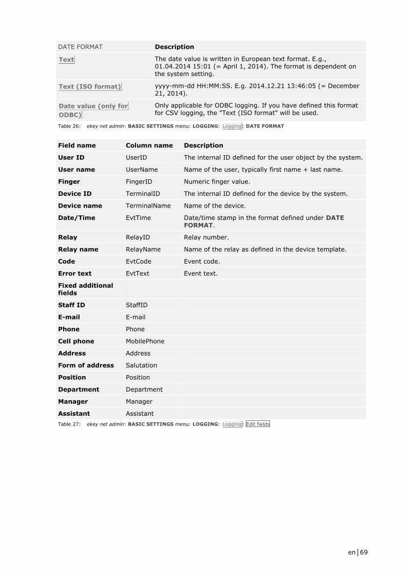
en│69
DATE FORMAT Description
Text The date value is written in European text format. E.g., 01.04.2014 15:01 (= April 1, 2014). The format is dependent on the system setting.
Text (ISO format) yyyy-mm-dd HH:MM:SS. E.g. 2014.12.21 13:46:05 (= December 21, 2014).
Date value (only for
ODBC)
Only applicable for ODBC logging. If you have defined this format for CSV logging, the "Text (ISO format" will be used.
Table 26: ekey net admin: BASIC SETTINGS menu: LOGGING: Logging: DATE FORMAT
Field name Column name Description
User ID UserID The internal ID defined for the user object by the system.
User name UserName Name of the user, typically first name + last name.
Finger FingerID Numeric finger value.
Device ID TerminalID The internal ID defined for the device by the system.
Device name TerminalName Name of the device.
Date/Time EvtTime Date/time stamp in the format defined under DATE FORMAT.
Relay RelayID Relay number.
Relay name RelayName Name of the relay as defined in the device template.
Code EvtCode Event code.
Error text EvtText Event text.
Fixed additional fields
Staff ID StaffID
E-mail E-mail
Phone Phone
Cell phone MobilePhone
Address Address
Form of address Salutation
Position Position
Department Department
Manager Manager
Assistant Assistant
Table 27: ekey net admin: BASIC SETTINGS menu: LOGGING: Logging: Edit fields

en│70
FingerID Finger Description
0 - Non-defined finger, e.g., event without FingerID.
1 F00 Left little finger
2 F01 Left ring finger
3 F02 Left middle finger
4 F03 Left index finger
5 F04 Left thumb
6 F05 Right thumb
7 F06 Right index finger
8 F07 Right middle finger
9 F08 Right ring finger
10 F09 Right little finger
Table 28: ekey net admin: BASIC SETTINGS menu: LOGGING: Logging: Edit fields: Finger/FingerID
Relay/RelayID Description
-1 Relay not defined, e.g., event without relay.
1 First relay
2 Second relay
3 Third relay
4 Fourth relay
Table 29: ekey net admin: BASIC SETTINGS menu: LOGGING: Logging: Edit fields: Relay/RelayID
NOTICE
Under Edit fields, you also have the option of using all the Fixed additional fields that are enabled
at the time.
ATTENTION
Each CSV file has its own individual fields, which are arranged in a specific order.
If you change the fields or the order without creating a new log file or renaming the old one, your
CSV file will have a different number of fields or the meaning of the fields will change.
You must create a new CSV file or rename the old one.
ekey net master server logging category
The ekey net master server collects the log entries for all the ekey net terminal servers defined in
the system and keeps them in one central location.
NOTICE
If the ekey net master server logging category is not enabled, you must enable it by entering the
password under LOGGING CONTROL PASSWORD in the Logging category.

en│71
LOG DATA Select the logging method that you want the ekey net master
server to use here.
PATH FOR CSV FILE If you have selected either of the two CSV logging methods, enter a file name with a valid path as the log destination here, e.g.,
C:\ekey net\logging\ekeynet.csv. The log file is renamed
automatically as soon as it reaches a size of 8 MB.
DSN FOR DATABASE ACCESS (ODBC)
If you are using ODBC logging, specify the system DSN name for the ODBC connection here.
USER If you are using ODBC logging, specify the user name for the ODBC connection here if you have defined one.
PASSWORD If you are using ODBC logging, specify the password for the
ODBC connection here if you have defined one.
TIME RECORDING LOG If you specify a file name with a valid path in this field, a CSV file will be created purely for the purpose of recording accesses. This CSV file has no header. In order for this type of logging to work,
you must check ENABLE FOR TIME RECORDING under the
finger scanner settings for all the finger scanners involved in this logging process.
LOG DATA Description
Do not save log data The ekey net master server does not performing any logging activities. The most recent events can be viewed in ekey net admin.
Save log data The ekey net master server saves the log data using the internal format. File: "ekeynetmasterserver_NBNAME.log".
Save log data in CSV file
(Unicode)
The log data is saved as a CSV file in Unicode format.
Save log data in CSV file
(ANSI)
The log data is saved as a CSV file in ASCII format.
Save log data in ODBC The log data is recorded using ODBC (MS SQL Server or MS Access database).
Table 30: ekey net admin: BASIC SETTINGS menu: LOGGING: ekey net master server logging: LOG DATA
TIME RECORDING LOG Description
UserID The internal ID defined for the user object by the system.
UserName Name of the user, typically first name + last name. If you have
assigned a staff ID number to the user, this is used instead of the name.
FingerID Numeric finger value in the following form: F00 to F09.
DeviceName Name of the device.
DateTime Date/time stamp in the format defined under DATE FORMAT.
Relay Relay number.
Table 31: ekey net admin: BASIC SETTINGS menu: LOGGING: ekey net master server logging: TIME RECORDING LOG
Web logging category
You can send the log data via HTTP.

en│72
ATTENTION
The log data is sent unencrypted.
There is a risk of others misusing your log data.
Therefore, you should not send the log data over the Internet for security reasons.
NOTICE
If the Web logging category is not enabled, you must enable it by entering the password under
LOGGING CONTROL PASSWORD in the Logging category.
See Configuring web logging operations, page 77.
WEB LOGGING Enable/disable web logging here.
ONLY USE ACTION CODES CONTAINING TEXT
The web log command is only sent if the action code contains actual text. You can use the next eight options to change the text. This only applies to web logging operations.
ACTION CODE "ACCESS" Define the name of the "Access" action code. Access is the
default setting.
ACTION CODE "EXIT" Define the name of the "Exit" action code. Exit is the default
setting.
ACTION CODE "REFUSED" Define the name of the "Refused" action code. Refused is the
default setting.
ACTION CODE
"UNRECOGNIZED FINGER"
Define the name of the "Unrecognized finger" action code.
Unrecognized finger is the default setting.
ACTION CODE "INTRUSION ALARM
SYSTEM ON"
Define the name of the "Intrusion alarm system on" action code.
Intrusion alarm system on is the default setting.
ACTION CODE " INTRUSION ALARM SYSTEM OFF"
Define the name of the "Intrusion alarm system off" action code.
Intrusion alarm system off is the default setting.
ACTION CODE "RESTART DEVICE"
Define the name of the "Restart device" action code. Restart
device is the default setting.
ACTION CODE "SWITCH" Define the name of the "Switch" action code. Switch is the
default setting.
Reporting category
Define the reporting settings here.
ENABLE REPORTING Enable/disable reporting here.
DSN Specify the system DSN for reporting here.
USER NAME Specify the name of the MS SQL Server user account for the DSN.
PASSWORD Specify the password for the MS SQL Server user account.
See Configuring reporting in ekey net admin , page 80.

en│73
10.9.7.1 Defining/changing the logging control password
Fig. 56: ekey net admin: LOGGING menu: Logging control : Password: Logging control
Follow the steps described below to change the logging control password:
Step Instruction
1st Go to BASIC SETTINGS – LOGGING.
2nd On the top right-hand side, click on Password under Logging control . The Logging
control dialog appears.
3rd Enter the currently valid password under Old password. The Change password check box
is enabled as soon as the password is entered correctly.
4th Click on the check box.
5th Enter a new password. If you leave the password blank, it will be removed altogether.
6th Enter the new password again.
7th Press OK.
The new password has been saved.
10.10 The wizard
The wizard makes it easier to configure the system. It will guide you step by step through the
configuration process.
The wizard starts automatically when you first log into the system and keeps on appearing until the
basic configuration steps have been completed.
NOTICE
If you attempt to use more finger scanners than are licensed, the wizard will only start up with the
Company or Calendar page.
To open the wizard manually, access it via the START menu. You can skip individual configuration
pages.

en│74
WIZARD Starts the wizard.
COMPANY
Define the company name.
Define the office hours for the default time zone Office hours. You
can only do this once. After that, you will have to edit the time zone manually.
Specify a calendar for the system.
CALENDAR
Specify a calendar for the system.
CREATE USER GROUP
Create or delete some user groups.
CREATE USERS Add users and assign them to user groups.
ENROLL FINGER Add reference finger scans and assign events to them.
ADDITIONAL USER DATA Enter additional user data.
ASSIGN EKEY NET
TERMINAL SERVER
Create an ekey net terminal server.
ADD EKEY NET CONVERTER LAN
Search for the ekey net converter LAN and incorporate it into the system.
ADD DEVICE Search for the finger scanners and control panels, and
incorporate them into the system.
EXIT WIZARD Terminates the wizard.
See USER menu, page 30.
See ekey net terminal server, page 36.
See Adding ekey net converter LANs, page 40.
See Adding a , page 42.
See Adding , page 46.
See Adding an RFID reader, page 50.
NOTICE
Once all the licenses are in use, you will not be able to create any more devices in the ekey net
using the wizard. A search for devices will not return any new devices. Create any additional
control panels manually.
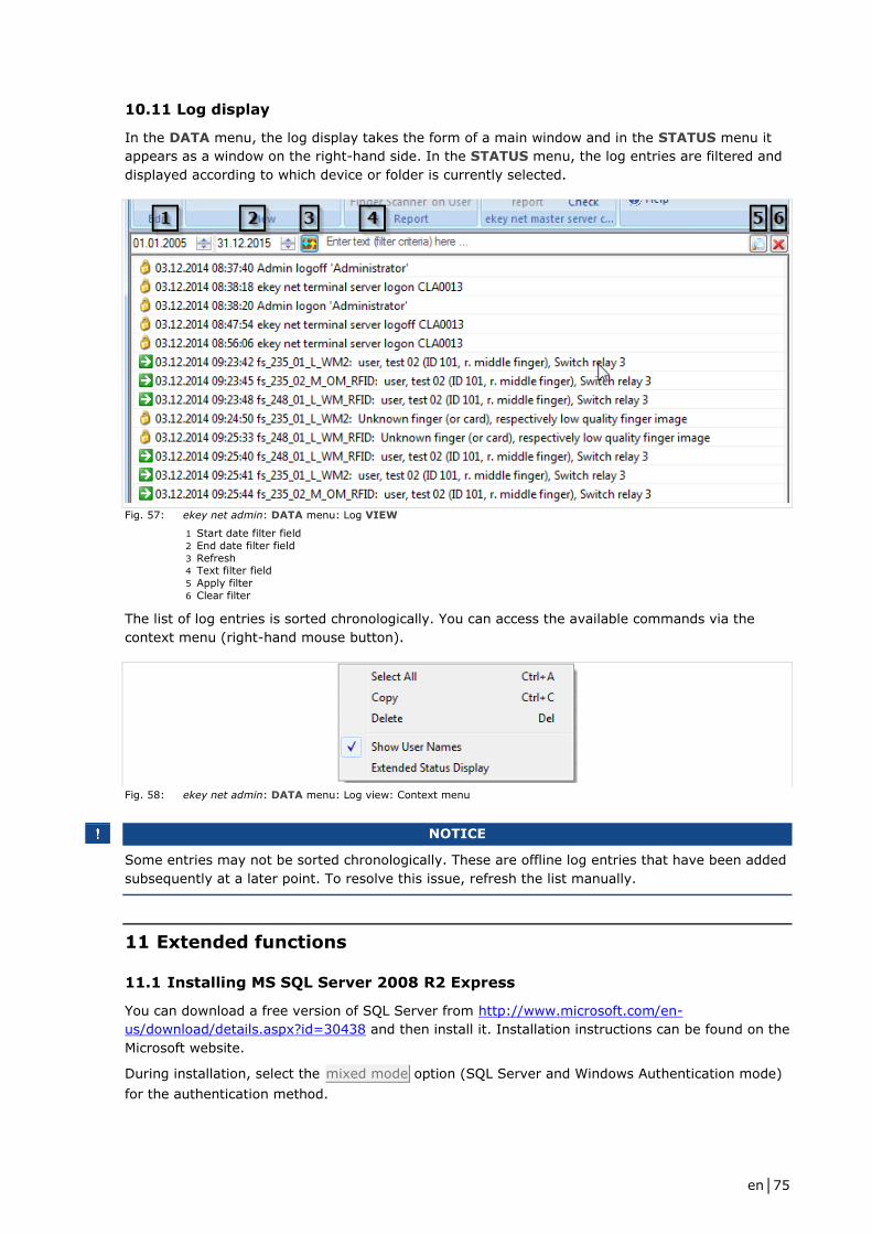
en│75
10.11 Log display
In the DATA menu, the log display takes the form of a main window and in the STATUS menu it
appears as a window on the right-hand side. In the STATUS menu, the log entries are filtered and
displayed according to which device or folder is currently selected.
Fig. 57: ekey net admin: DATA menu: Log VIEW
1 Start date filter field
2 End date filter field
3 Refresh 4 Text filter field
5 Apply filter
6 Clear filter
The list of log entries is sorted chronologically. You can access the available commands via the
context menu (right-hand mouse button).
Fig. 58: ekey net admin: DATA menu: Log view: Context menu
NOTICE
Some entries may not be sorted chronologically. These are offline log entries that have been added
subsequently at a later point. To resolve this issue, refresh the list manually.
11 Extended functions
11.1 Installing MS SQL Server 2008 R2 Express
You can download a free version of SQL Server from http://www.microsoft.com/en-
us/download/details.aspx?id=30438 and then install it. Installation instructions can be found on the
Microsoft website.
During installation, select the mixed mode option (SQL Server and Windows Authentication mode)
for the authentication method.
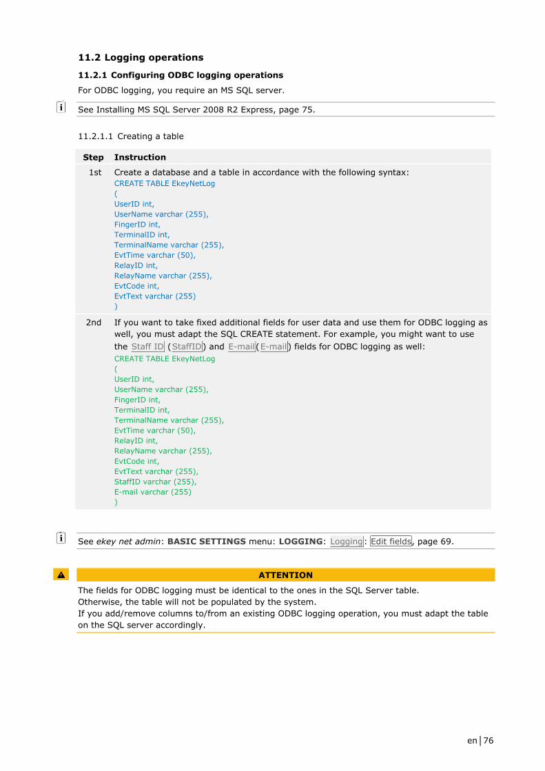
en│76
11.2 Logging operations
11.2.1 Configuring ODBC logging operations
For ODBC logging, you require an MS SQL server.
See Installing MS SQL Server 2008 R2 Express, page 75.
11.2.1.1 Creating a table
Step Instruction
1st Create a database and a table in accordance with the following syntax:
CREATE TABLE EkeyNetLog
(
UserID int,
UserName varchar (255),
FingerID int,
TerminalID int,
TerminalName varchar (255),
EvtTime varchar (50),
RelayID int,
RelayName varchar (255),
EvtCode int,
EvtText varchar (255)
)
2nd If you want to take fixed additional fields for user data and use them for ODBC logging as
well, you must adapt the SQL CREATE statement. For example, you might want to use
the Staff ID (StaffID) and E-mail(E-mail) fields for ODBC logging as well:
CREATE TABLE EkeyNetLog
(
UserID int,
UserName varchar (255),
FingerID int,
TerminalID int,
TerminalName varchar (255),
EvtTime varchar (50),
RelayID int,
RelayName varchar (255),
EvtCode int,
EvtText varchar (255),
StaffID varchar (255),
E-mail varchar (255)
)
See ekey net admin: BASIC SETTINGS menu: LOGGING: Logging: Edit fields, page 69.
ATTENTION
The fields for ODBC logging must be identical to the ones in the SQL Server table.
Otherwise, the table will not be populated by the system.
If you add/remove columns to/from an existing ODBC logging operation, you must adapt the table
on the SQL server accordingly.
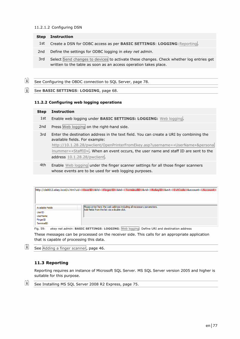
en│77
11.2.1.2 Configuring DSN
Step Instruction
1st Create a DSN for ODBC access as per BASIC SETTINGS: LOGGING:Reporting.
2nd Define the settings for ODBC logging in ekey net admin.
3rd Select Send changes to devices to activate these changes. Check whether log entries get
written to the table as soon as an access operation takes place.
See Configuring the OBDC connection to SQL Server, page 78.
See BASIC SETTINGS: LOGGING, page 68.
11.2.2 Configuring web logging operations
Step Instruction
1st Enable web logging under BASIC SETTINGS: LOGGING: Web logging.
2nd Press Web logging on the right-hand side.
3rd Enter the destination address in the text field. You can create a URI by combining the
available fields. For example:
http://10.1.28.28/pwclient/OpenPrinterFromEkey.asp?username=«UserName»&persona
lnummer=«StaffID». When an event occurs, the user name and staff ID are sent to the
address 10.1.28.28/pwclient.
4th Enable Web logging under the finger scanner settings for all those finger scanners
whose events are to be used for web logging purposes.
Fig. 59: ekey net admin: BASIC SETTINGS: LOGGING: Web logging: Define URI and destination address
These messages can be processed on the receiver side. This calls for an appropriate application
that is capable of processing this data.
See Adding a finger scanner, page 46.
11.3 Reporting
Reporting requires an instance of Microsoft SQL Server. MS SQL Server version 2005 and higher is
suitable for this purpose.
See Installing MS SQL Server 2008 R2 Express, page 75.
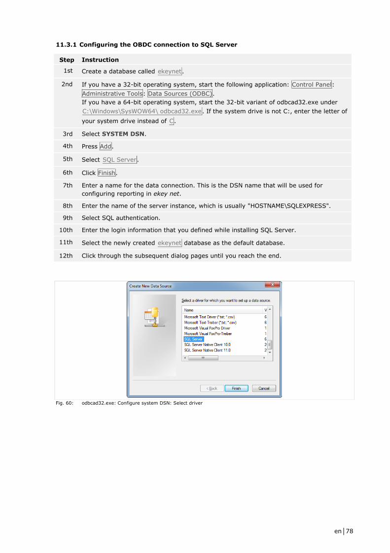
en│78
11.3.1 Configuring the OBDC connection to SQL Server
Step Instruction
1st Create a database called ekeynet.
2nd If you have a 32-bit operating system, start the following application: Control Panel:
Administrative Tools: Data Sources (ODBC).
If you have a 64-bit operating system, start the 32-bit variant of odbcad32.exe under
C:\Windows\SysWOW64\ odbcad32.exe. If the system drive is not C:, enter the letter of
your system drive instead of C.
3rd Select SYSTEM DSN.
4th Press Add.
5th Select SQL Server.
6th Click Finish.
7th Enter a name for the data connection. This is the DSN name that will be used for
configuring reporting in ekey net.
8th Enter the name of the server instance, which is usually "HOSTNAME\SQLEXPRESS".
9th Select SQL authentication.
10th Enter the login information that you defined while installing SQL Server.
11th Select the newly created ekeynet database as the default database.
12th Click through the subsequent dialog pages until you reach the end.
Fig. 60: odbcad32.exe: Configure system DSN: Select driver
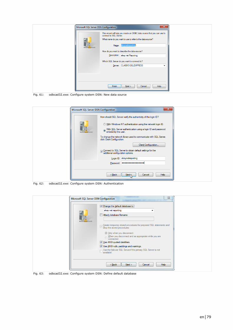
en│79
Fig. 61: odbcad32.exe: Configure system DSN: New data source
Fig. 62: odbcad32.exe: Configure system DSN: Authentication
Fig. 63: odbcad32.exe: Configure system DSN: Define default database
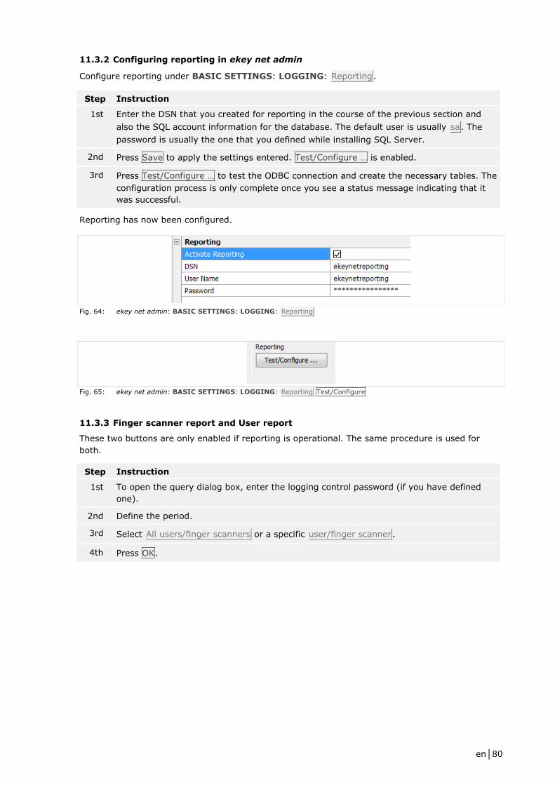
en│80
11.3.2 Configuring reporting in ekey net admin
Configure reporting under BASIC SETTINGS: LOGGING: Reporting.
Step Instruction
1st Enter the DSN that you created for reporting in the course of the previous section and
also the SQL account information for the database. The default user is usually sa. The
password is usually the one that you defined while installing SQL Server.
2nd Press Save to apply the settings entered. Test/Configure … is enabled.
3rd Press Test/Configure … to test the ODBC connection and create the necessary tables. The
configuration process is only complete once you see a status message indicating that it
was successful.
Reporting has now been configured.
Fig. 64: ekey net admin: BASIC SETTINGS: LOGGING: Reporting
Fig. 65: ekey net admin: BASIC SETTINGS: LOGGING: Reporting Test/Configure
11.3.3 Finger scanner report and User report
These two buttons are only enabled if reporting is operational. The same procedure is used for
both.
Step Instruction
1st To open the query dialog box, enter the logging control password (if you have defined
one).
2nd Define the period.
3rd Select All users/finger scanners or a specific user/finger scanner.
4th Press OK.
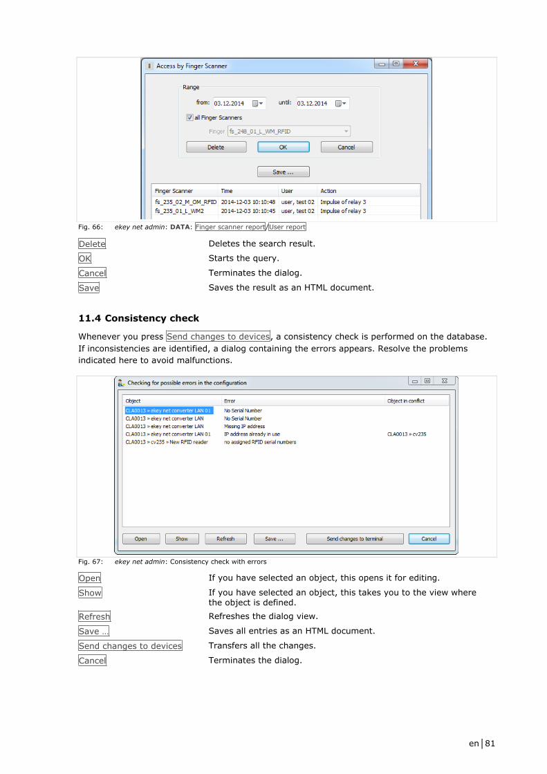
en│81
Fig. 66: ekey net admin: DATA: Finger scanner report/User report
Delete Deletes the search result.
OK Starts the query.
Cancel Terminates the dialog.
Save Saves the result as an HTML document.
11.4 Consistency check
Whenever you press Send changes to devices, a consistency check is performed on the database.
If inconsistencies are identified, a dialog containing the errors appears. Resolve the problems
indicated here to avoid malfunctions.
Fig. 67: ekey net admin: Consistency check with errors
Open If you have selected an object, this opens it for editing.
Show If you have selected an object, this takes you to the view where the object is defined.
Refresh Refreshes the dialog view.
Save … Saves all entries as an HTML document.
Send changes to devices Transfers all the changes.
Cancel Terminates the dialog.
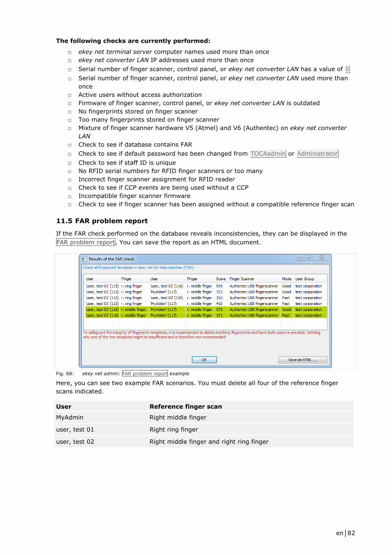
en│82
The following checks are currently performed:
□ ekey net terminal server computer names used more than once
□ ekey net converter LAN IP addresses used more than once
□ Serial number of finger scanner, control panel, or ekey net converter LAN has a value of 0
□ Serial number of finger scanner, control panel, or ekey net converter LAN used more than
once
□ Active users without access authorization
□ Firmware of finger scanner, control panel, or ekey net converter LAN is outdated
□ No fingerprints stored on finger scanner
□ Too many fingerprints stored on finger scanner
□ Mixture of finger scanner hardware V5 (Atmel) and V6 (Authentec) on ekey net converter
LAN
□ Check to see if database contains FAR
□ Check to see if default password has been changed from TOCAadmin or Administrator
□ Check to see if staff ID is unique
□ No RFID serial numbers for RFID finger scanners or too many
□ Incorrect finger scanner assignment for RFID reader
□ Check to see if CCP events are being used without a CCP
□ Incompatible finger scanner firmware
□ Check to see if finger scanner has been assigned without a compatible reference finger scan
11.5 FAR problem report
If the FAR check performed on the database reveals inconsistencies, they can be displayed in the
FAR problem report. You can save the report as an HTML document.
Fig. 68: ekey net admin: FAR problem report example
Here, you can see two example FAR scenarios. You must delete all four of the reference finger
scans indicated.
User Reference finger scan
MyAdmin Right middle finger
user, test 01 Right ring finger
user, test 02 Right middle finger and right ring finger

en│83
11.6 Attendance list
To ensure that the attendance list is displayed correctly, you must record whenever a user obtains
access or exits. There are two different ways of doing this.
NOTICE
Given that organizational (rather than technical) measures are normally used to record when a
user gains access and exits, the attendance list is not guaranteed to work 100% reliably. It would,
for example, be necessary to install a turnstile for accessing and exiting a building so that people
could only enter and leave via this route.
Recording attendance with two different reference finger scans per user
Assign an access event to one reference finger scan and an exit event to the other. The user
swipes their first finger when they enter the building and their second finger when they exit it.
Advantage Easy to configure No additional finger scanner required
Can be performed on any finger scanner for which the user is authorized
Disadvantage Usage
Recording attendance with two finger scanners
The user relies on one finger scanner to access the building and uses the other one to exit it.
Advantage Easier to use
Disadvantage Second finger scanner required Users may forget to "check out"
Before you can record when a user accesses and exits the building, you must first define an exit
action and an exit event. Default events and actions already exist for the access scenario.
11.6.1 Defining an exit event and action
Step Instruction
1st Create an action with the Exit ACTION CODE but no other settings.
2nd Create an event that relies on the Exit action.
Fig. 69: Customized exit action and event
See Creating a customized action, page 59.
See Creating a customized event, page 63.

en│84
11.6.2 Recording attendance with two different reference finger scans per user
Step Instruction
1st Register (enroll) two reference finger scans for each user.
2nd Assign an event to the finger that is to be used for access. This event must rely on the
Access ACTION CODE, e.g., Open door with finger. In this way, the user can signal that
they are present.
3rd Assign the previously defined exit event to the finger that is to be used for exiting the
building. In this way, the user can signal that they are absent.
11.6.3 Recording attendance with one reference finger scan per user
Provide a finger scanner for the sole purpose of recording attendance/absence based on one
reference finger scan. This finger scanner is not responsible for any other task.
Each user can use any finger scanner within the system for which they are authorized to signal that
they are present. The only exception in this regard is the finger scanner they use to signal their
absence.
Step Instruction
1st Create a customized device template. This converts the Open door with finger event into
the exit event that you created previously.
2nd Assign the device template that you have just created to the finger scanner that is
responsible for recording when a user exits. This finger scanner will then perform the exit
event for all those assigned reference scans that have the Open door with finger event
assigned to them.
See Creating a customized device template, page 65.
11.6.4 Working with the attendance list
The attendance list shows which system users are present. It can be accessed in the DATA menu
and in the STATUS menu via Show attendance list. If you have defined a password for logging
control, the dialog for entering it appears.
See Defining/changing the logging control password, page 73.
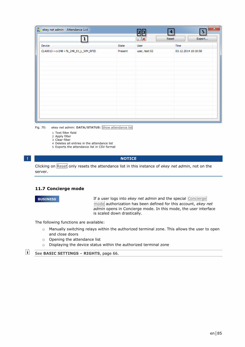
en│85
Fig. 70: ekey net admin: DATA/STATUS: Show attendance list
1 Text filter field
2 Apply filter
3 Clear filter
4 Deletes all entries in the attendance list
5 Exports the attendance list in CSV format
NOTICE
Clicking on Reset only resets the attendance list in this instance of ekey net admin, not on the
server.
11.7 Concierge mode
If a user logs into ekey net admin and the special Concierge
mode authorization has been defined for this account, ekey net
admin opens in Concierge mode. In this mode, the user interface is scaled down drastically.
The following functions are available:
□ Manually switching relays within the authorized terminal zone. This allows the user to open
and close doors
□ Opening the attendance list
□ Displaying the device status within the authorized terminal zone
See BASIC SETTINGS – RIGHTS, page 66.
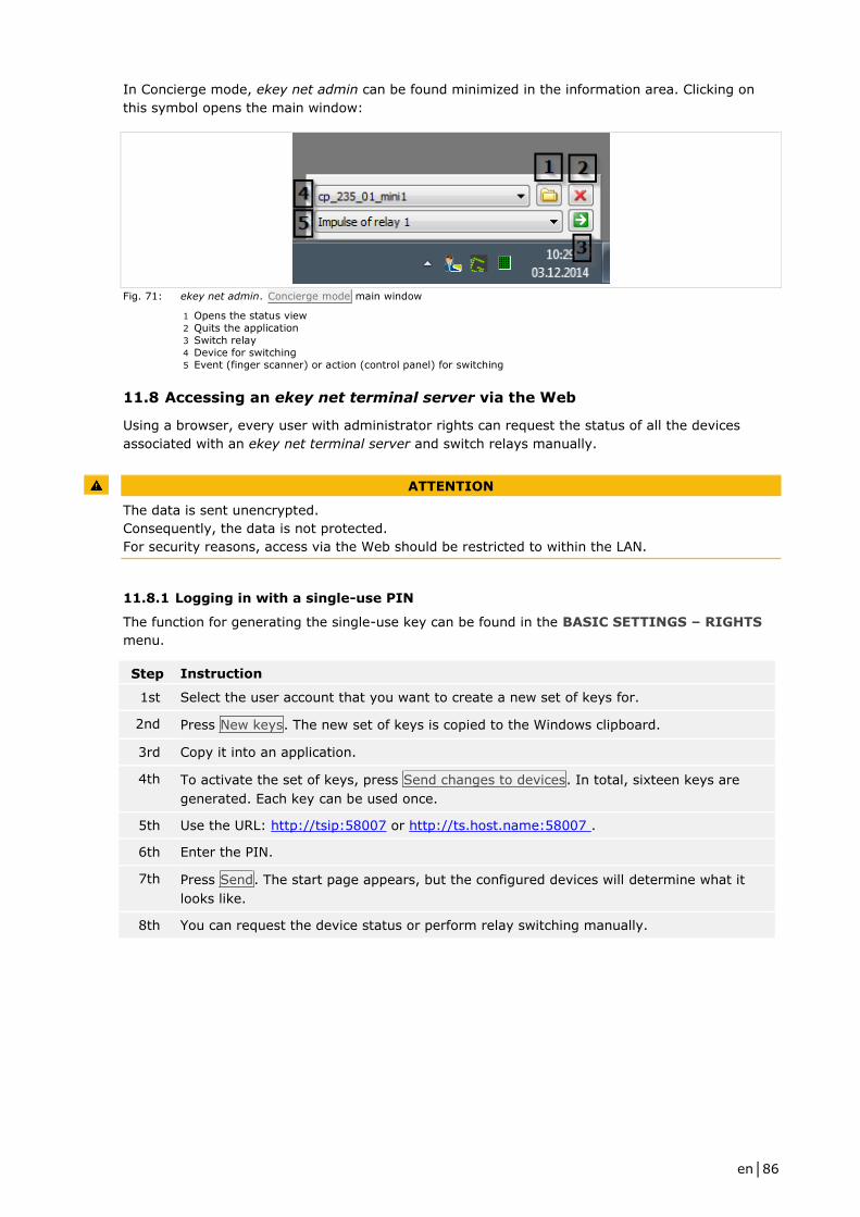
en│86
In Concierge mode, ekey net admin can be found minimized in the information area. Clicking on
this symbol opens the main window:
Fig. 71: ekey net admin. Concierge mode main window
1 Opens the status view
2 Quits the application
3 Switch relay
4 Device for switching 5 Event (finger scanner) or action (control panel) for switching
11.8 Accessing an ekey net terminal server via the Web
Using a browser, every user with administrator rights can request the status of all the devices
associated with an ekey net terminal server and switch relays manually.
ATTENTION
The data is sent unencrypted.
Consequently, the data is not protected.
For security reasons, access via the Web should be restricted to within the LAN.
11.8.1 Logging in with a single-use PIN
The function for generating the single-use key can be found in the BASIC SETTINGS – RIGHTS
menu.
Step Instruction
1st Select the user account that you want to create a new set of keys for.
2nd Press New keys. The new set of keys is copied to the Windows clipboard.
3rd Copy it into an application.
4th To activate the set of keys, press Send changes to devices. In total, sixteen keys are
generated. Each key can be used once.
5th Use the URL: http://tsip:58007 or http://ts.host.name:58007 .
6th Enter the PIN.
7th Press Send. The start page appears, but the configured devices will determine what it
looks like.
8th You can request the device status or perform relay switching manually.
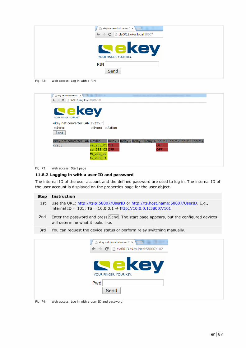
en│87
Fig. 72: Web access: Log in with a PIN
Fig. 73: Web access: Start page
11.8.2 Logging in with a user ID and password
The internal ID of the user account and the defined password are used to log in. The internal ID of
the user account is displayed on the properties page for the user object.
Step Instruction
1st Use the URL: http://tsip:58007/UserID or http://ts.host.name:58007/UserID. E.g.,
internal ID = 101; TS = 10.0.0.1 http://10.0.0.1:58007/101
2nd Enter the password and press Send. The start page appears, but the configured devices
will determine what it looks like.
3rd You can request the device status or perform relay switching manually.
Fig. 74: Web access: Log in with a user ID and password

en│88
11.9 Power-on reset special configuration
If the entire RS-485 bus is detrimentally affected by an ESD impulse, the power-on reset control
panel on this RS-485 bus may no longer be able to restart the finger scanner. So that the finger
scanner can be restarted in such cases, you must install additional hardware (an ekey net
converter LAN and an ekey net control panel) plus special cabling.
The control panel on the second RS-485 bus must be assigned as a power-on reset control panel to
the finger scanner you want to monitor.
Fig. 75: Power-on reset special configuration
1 The finger scanner blocks the RS-485 with an ESD impulse.
2 The ekey net terminal server monitors the status of the RS-485 bus via the ekey net converter LAN and detects a
fault.
3 The ekey net terminal server switches the power-on reset via the control panel on the second RS-485 bus.
4 The second control panel on the second RS-485 bus ensures that the finger scanner restarts.

en│89
11.10 Composite control panel
NOTICE
If you are using a CCP, you can connect up to seven control panels and one finger scanner on the
RS-485 bus.
All the control panels that belong to a single CCP must be connected on the same RS-485 bus.
Follow the steps described below if you want to use a CCP:
Step Instruction
1st Create and configure the control panel and the CCP.
2nd Create and configure a finger scanner.
3rd Assign a finger scanner to the CCP.
4th Assign some reference finger scans for the relevant user to a CCP event.
5th Press Send changes to devices to complete the configuration process.
6th Test the settings.
See Editing a composite control panel, page 43.
See Adding a finger scanner, page 46.
See Creating/editing users, page 30.
NOTICE
The CCP is subject to the following restrictions:
□ Do not use any customized device templates for the finger scanner to which the CCP has
been assigned
□ Do not use any customized events that trigger a second action (Action when counter ends)
11.11 Automatic time-controlled operation for a control panel
Step Instruction
1st Create a time zone with all the necessary time slots.
2nd Check USE TIME ZONE FOR TIME-CONTROLLED OPERATION for this time zone.
3rd Assign the time zone to a control panel and to the relay that is to be responsible for
automatic time-controlled switching.
NOTICE
If you remove an automatic time-controlled operation setting from a control panel, you must
switch off the relay of this control panel manually.

en│90
11.12 Action boundaries
You can configure a customized action so that it is effective within a device zone right up to the
action boundary. You can define the action boundary for the following types of object: ekey net
converter LAN, terminal group, or ekey net terminal server.
The ekey net converter LAN is always implicitly defined as the action boundary by default if you
have not specified an action boundary in relation to this object or a higher-level one.
NOTICE
If you have not defined an action boundary for any of the relevant objects in the system, the ekey
net converter LAN always serves as the action boundary. When an action with an action boundary
is triggered, it is performed by all devices on the RS-485 bus of the ekey net converter LAN.
NOTICE
Without exception, none of the default actions within the system use zone switching.
11.12.1 Defining action boundaries
Follow the steps described below to enable the action boundary for the following types of object:
ekey net converter LAN, terminal group, or ekey net terminal server:
Step Instruction
1st Open the object.
2nd Enable Action boundary.
See Editing an ekey net terminal server, page 37
See Editing a terminal group, page 38.
See Adding ekey net converter LANs, page 40.
11.12.2 Creating a customized action with zone switching
Step Instruction
1st Create a customized action. The Device option of the customized action is the only one
that plays a definitive role in zone switching.
2nd Select one of the zone properties under All devices within zone – relay n.
See Creating a customized action, page 59.
11.12.3 Creating a customized event with zone switching
Step Instruction
1st Create a customized event.
2nd Under Action, assign a customized zone switching action to the event.
See Creating a customized event, page 63.

en│91
ATTENTION
An event cannot trigger two actions with zone switching.
In this case, the zone switching will not work.
Do not use the Action when counter ends property.
11.12.4 Assigning a customized event to reference finger scans
Step Instruction
1st Assign the customized event to the required reference finger scans.
2nd Press Send changes to devices to complete the configuration process.
See Enroll finger properties page, page 31.
11.13 Keep-switched function
Step Instruction
1st Create a time zone with time slots that will activate the keep-switched function.
2nd Assign an event to some reference finger scans of the relevant users. This event must be
one already assigned to an action with the keep-switched function enabled.
3rd Create an access authorization assignment between the time zone and the user group.
4th Select Send changes to devices to complete the configuration process.
5th Test the settings.
See Time zone, page 52.
See BASIC SETTINGS – ACTIONS, page 59.
See BASIC SETTINGS – EVENTS, page 62.
See Creating/editing users, page 30.
See AUTHORIZATIONS menu, page 55.
11.14 UDP transmission
The system can send defined data packets via UDP based on events at the finger scanner. You can
use the ekey net terminal server or the ekey net converter LAN as the sender.
NOTICE
Do not use them both. Otherwise, you will receive the packets from the ekey net terminal server as
well as the ekey net converter LAN.
To debug UDP transmission, use a suitable network protocol analysis program such as Wireshark.
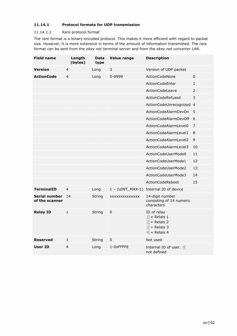
en│92
11.14.1 Protocol formats for UDP transmission
11.14.1.1 Rare protocol format
The rare format is a binary-encoded protocol. This makes it more efficient with regard to packet
size. However, it is more extensive in terms of the amount of information transmitted. The rare
format can be sent from the ekey net terminal server and from the ekey net converter LAN.
Field name Length
(bytes)
Data
type
Value range Description
Version 4 Long 3 Version of UDP packet
ActionCode 4 Long 0-9999 ActionCodeNone 0
ActionCodeEnter 1
ActionCodeLeave 2
ActionCodeRefused 3
ActionCodeUnrecognized 4
ActionCodeAlarmDevOn 5
ActionCodeAlarmDevOff 6
ActionCodeAlarmLevel0 7
ActionCodeAlarmLevel1 8
ActionCodeAlarmLevel2 9
ActionCodeAlarmLevel3 10
ActionCodeUserMode0 11
ActionCodeUserMode1 12
ActionCodeUserMode2 13
ActionCodeUserMode3 14
ActionCodeReboot 15
TerminalID 4 Long 1 – (UINT_MAX-1) Internal ID of device
Serial number of the scanner
14 String xxxxxxxxxxxxxx 14-digit number consisting of 14 numeric
characters
Relay ID 1 String 0 ID of relay
1 = Relais 1
2 = Relais 2
3 = Relais 3
4 = Relais 4
Reserved 1 String 0 Not used
User ID 4 Long 1-0xFFFFE Internal ID of user. 0
not defined

en│93
Field name Length (bytes)
Data type
Value range Description
Finger ID 4 Long 0-10, 16 ID of finger
1 = left little finger
2 = left ring finger
3 = left middle finger
4 = left index finger
5 = left thumb
6 = right thumb
7 = right index finger
8 = right middle finger
9 = right ring finger
10 = right little finger
16 = RFID
Event 16 String xxxxxxxxxxxxxxxx
Time 16 String yyyymmdd hhmmss
yyyymmdd hhmmss
Name 2 Short 0 Name of the user as a
Unicode string (if available; otherwise: empty)
Staff ID 2 Short 0 StaffID (if available; otherwise: empty)
Table 32: UDP transmission: Rare protocol format
NOTICE
□ ActionCode sent from ekey net terminal server as specified in the description. The ekey net
converter LAN sends the EventID that is assigned to each event.
□ For Event, the first 16 characters of the event name are sent from the ekey net terminal
server. The ekey net converter LAN sends an empty string.
□ For Name, the user name is sent from the ekey net terminal server as a Unicode string.
The ekey net converter LAN sends an empty string.
□ For Staff ID, the staff ID is sent from the ekey net terminal server. The ekey net converter
LAN sends an empty string.
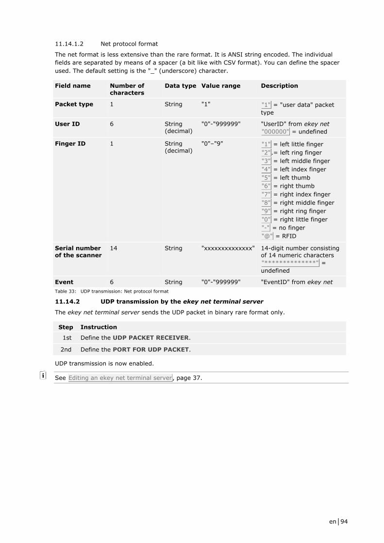
en│94
11.14.1.2 Net protocol format
The net format is less extensive than the rare format. It is ANSI string encoded. The individual
fields are separated by means of a spacer (a bit like with CSV format). You can define the spacer
used. The default setting is the "_" (underscore) character.
Field name Number of characters
Data type Value range Description
Packet type 1 String "1" "1" = "user data" packet
type
User ID 6 String (decimal)
"0"-"999999" "UserID" from ekey net
"000000" = undefined
Finger ID 1 String (decimal)
"0"–"9" "1" = left little finger
"2".= left ring finger
"3" = left middle finger
"4" = left index finger
"5" = left thumb
"6" = right thumb
"7" = right index finger
"8" = right middle finger
"9" = right ring finger
"0" = right little finger
"-" = no finger
"@" = RFID
Serial number of the scanner
14 String "xxxxxxxxxxxxxx" 14-digit number consisting of 14 numeric characters
"**************" =
undefined
Event 6 String "0"-"999999" "EventID" from ekey net
Table 33: UDP transmission: Net protocol format
11.14.2 UDP transmission by the ekey net terminal server
The ekey net terminal server sends the UDP packet in binary rare format only.
Step Instruction
1st Define the UDP PACKET RECEIVER.
2nd Define the PORT FOR UDP PACKET.
UDP transmission is now enabled.
See Editing an ekey net terminal server, page 37.
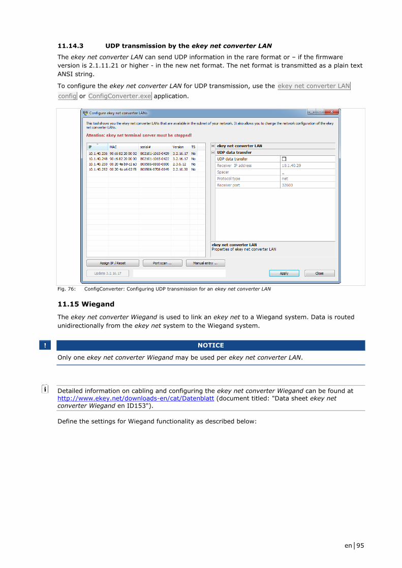
en│95
11.14.3 UDP transmission by the ekey net converter LAN
The ekey net converter LAN can send UDP information in the rare format or – if the firmware
version is 2.1.11.21 or higher - in the new net format. The net format is transmitted as a plain text
ANSI string.
To configure the ekey net converter LAN for UDP transmission, use the ekey net converter LAN
config or ConfigConverter.exe application.
Fig. 76: ConfigConverter: Configuring UDP transmission for an ekey net converter LAN
11.15 Wiegand
The ekey net converter Wiegand is used to link an ekey net to a Wiegand system. Data is routed
unidirectionally from the ekey net system to the Wiegand system.
NOTICE
Only one ekey net converter Wiegand may be used per ekey net converter LAN.
Detailed information on cabling and configuring the ekey net converter Wiegand can be found at
http://www.ekey.net/downloads-en/cat/Datenblatt (document titled: "Data sheet ekey net converter Wiegand en ID153").
Define the settings for Wiegand functionality as described below:

en│96
Step Instruction
1st Under BASIC SETTINGS – OPTIONS, check Use Wiegand ID.
2nd Create a customized device template for an ekey net converter Wiegand. This template
must contain the necessary settings for the Wiegand protocol. If you require the standard
26-bit protocol, you do not need to create a customized device template. The default
device template for an ekey net converter Wiegand is already configured with this in
mind.
3rd In the user properties, enter the Wiegand user ID under Additional user data for all
users.
4th In the finger scanner properties, enter the Wiegand ID for all the finger scanners that
you want to forward data to the Wiegand system.
5th Press Send changes to devices to complete the configuration process.
6th Test the settings.
Example of the Wiegand standard protocol (26 bits)
Total bit length 26
OEM bit length 0
FS ID bit length 8
UID bit length 16
OEM identifier 0
ID PE FS ID USER ID PO
Bit # 1 2 3 4 5 6 7 8 9 10 11 12 13 14 15 16 17 18 19 20 21 22 23 24 25 26
Relative bit #
1 1 2 3 4 5 6 7 8 1 2 3 4 5 6 7 8 9 10 11 12 13 14 15 16 1
Binary content
Table 34: Wiegand standard protocol (26 bits)
Example of the Wiegand Pyramid protocol (39 bits)
Total bit length 39
OEM bit length 0
FS ID bit length 17
UID bit length 20
OEM identifier 0
ID PE FS ID USER ID PO
Bit # 1 2 3 4 5 6 7 8 9 10 11 12 13 14 15 16 17 18 19 20 21 22 23 24 25 26 27 28 29 30 31 32 33 34 35 36 37 38 39
Relative bit
#
1 1 2 3 4 5 6 7 8 9 10 11 12 13 14 15 16 17 1 2 3 4 5 6 7 8 9 10 11 12 13 14 15 16 17 18 19 20 1
Binary
content
Table 35: Wiegand Pyramid protocol (39 bits)

en│97
Example of the Wiegand customized protocol (42 bits with OEM identifier)
Total bit length 42
OEM bit length 8
FS ID bit length 16
UID bit length 16
OEM identifier 7
ID PE OEM identifier FS ID USER ID PO
Bit # 1 2 3 4 5 6 7 8 9 10 11 12 13 14 15 16 17 18 19 20 21 22 23 24 25 26 27 28 29 30 31 32 33 34 35 36 37 38 39 40 41 42
Relative bit #
1 1 2 3 4 5 6 7 8 1 2 3 4 5 6 7 8 9 10 11 12 13 14 15 16 1 2 3 4 5 6 7 8 9 10 11 12 13 14 15 16 1
Binary
content
0 0 0 0 0 1 1 1
Table 36: Wiegand customized protocol (42 bits with OEM identifier)
ATTENTION
No validity check is performed on the Wiegand user ID of a user or the Wiegand ID of a finger
scanner.
If the numeric values exceed the bit length defined for the respective ID, the value is shortened to
this bit length and sent truncated.
Carefully check the bit length of the respective IDs.
11.16 ekey net SDK
The ekey net master server features a software interface that allows you to access the database
and logging system with external systems. If you wish to use this interface, please contact ekey.
12 Details concerning INI files
ekey net admin, ekey net master server, and ekey net terminal server are configured by means of
the following INI files: "ekeynetadmin.ini", "ekeynetmasterserver.ini", and
"ekeynetterminalserver.ini". The files are stored in folder C:\ProgramData\ekey\ekey net
(Windows Vista and higher) or C:\Documents and Settings\All Users\Application Data\ekey\ekey
net (Windows XP).
Example "ekeynetadmin.ini" file:
[Settings]
Path=E:\ekey net\admin
DiagnosticsPath=E:\ekey net\admin\diag
12.1 INI entries for ekey net admin
Make the entries within [Settings].
Value Description
Path Absolute path leading to the data folder for ekey net admin.
E.g., Path=c:\temp\admin
DiagnosticsPath Absolute path leading to the diagnostics folder for ekey net admin.
E.g., DiagnosticsPath=c:\temp\admim\diag
Table 37: INI entries for ekey net admin "ekeynetadmin.ini"
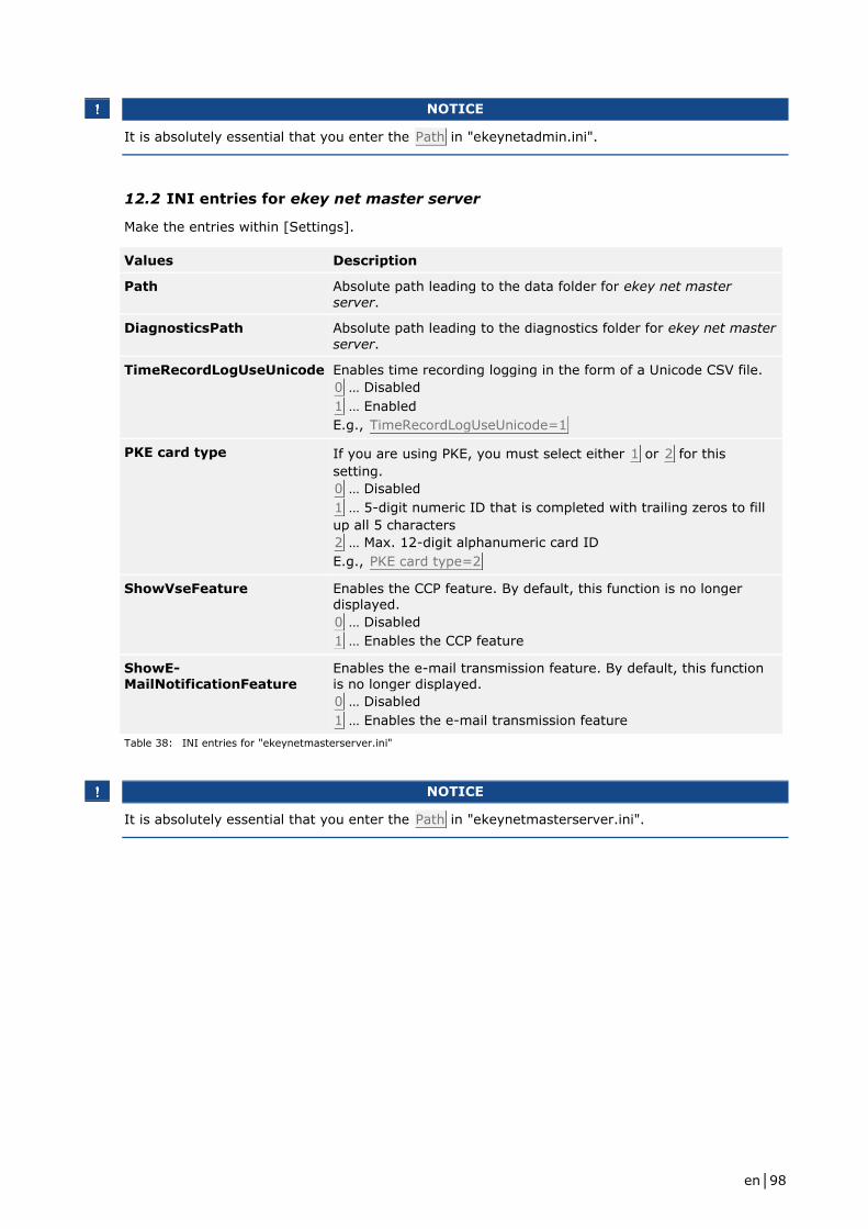
en│98
NOTICE
It is absolutely essential that you enter the Path in "ekeynetadmin.ini".
12.2 INI entries for ekey net master server
Make the entries within [Settings].
Values Description
Path Absolute path leading to the data folder for ekey net master
server.
DiagnosticsPath Absolute path leading to the diagnostics folder for ekey net master
server.
TimeRecordLogUseUnicode Enables time recording logging in the form of a Unicode CSV file.
0 … Disabled
1 … Enabled
E.g., TimeRecordLogUseUnicode=1
PKE card type If you are using PKE, you must select either 1 or 2 for this
setting.
0 … Disabled
1 … 5-digit numeric ID that is completed with trailing zeros to fill
up all 5 characters
2 … Max. 12-digit alphanumeric card ID
E.g., PKE card type=2
ShowVseFeature Enables the CCP feature. By default, this function is no longer displayed.
0 … Disabled
1 … Enables the CCP feature
ShowE-MailNotificationFeature
Enables the e-mail transmission feature. By default, this function is no longer displayed.
0 … Disabled
1 … Enables the e-mail transmission feature
Table 38: INI entries for "ekeynetmasterserver.ini"
NOTICE
It is absolutely essential that you enter the Path in "ekeynetmasterserver.ini".
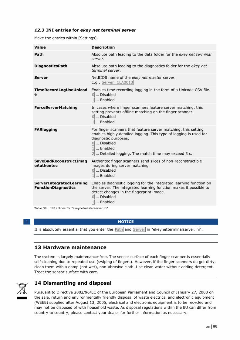
en│99
12.3 INI entries for ekey net terminal server
Make the entries within [Settings].
Value Description
Path Absolute path leading to the data folder for the ekey net terminal server.
DiagnosticsPath Absolute path leading to the diagnostics folder for the ekey net
terminal server.
Server NetBIOS name of the ekey net master server.
E.g., Server=CLA0013
TimeRecordLogUseUnicode
Enables time recording logging in the form of a Unicode CSV file.
0 … Disabled
1 … Enabled
ForceServerMatching In cases where finger scanners feature server matching, this setting prevents offline matching on the finger scanner.
0 … Disabled
1 … Enabled
FARlogging For finger scanners that feature server matching, this setting enables highly detailed logging. This type of logging is used for diagnostic purposes.
0 … Disabled
1 … Enabled
2 … Detailed logging. The match time may exceed 3 s.
SaveBadReconstructImag
eAuthentec
Authentec finger scanners send slices of non-reconstructible
images during server matching.
0 … Disabled
1 … Enabled
ServerIntegratedLearningFunctionDiagnostics
Enables diagnostic logging for the integrated learning function on the server. The integrated learning function makes it possible to
detect changes in the fingerprint image.
0 … Disabled
1 … Enabled
Table 39: INI entries for "ekeynetmasterserver.ini"
NOTICE
It is absolutely essential that you enter the Path and Server in "ekeynetterminalserver.ini".
13 Hardware maintenance
The system is largely maintenance-free. The sensor surface of each finger scanner is essentially
self-cleaning due to repeated use (swiping of fingers). However, if the finger scanners do get dirty,
clean them with a damp (not wet), non-abrasive cloth. Use clean water without adding detergent.
Treat the sensor surface with care.
14 Dismantling and disposal
Pursuant to Directive 2002/96/EC of the European Parliament and Council of January 27, 2003 on
the sale, return and environmentally friendly disposal of waste electrical and electronic equipment
(WEEE) supplied after August 13, 2005, electrical and electronic equipment is to be recycled and
may not be disposed of with household waste. As disposal regulations within the EU can differ from
country to country, please contact your dealer for further information as necessary.

en│100
15 Declaration of conformity
ekey biometric systems GmbH hereby declares that the product conforms to the relevant
provisions of the Electromagnetic Compatibility Directive 2004/108/EC of the European Union. The
complete text of the declaration of conformity can be downloaded from
http://www.ekey.net/downloads.
16 Copyright
Copyright © 2015 ekey biometric systems GmbH.
All content, artwork, and any ideas contained in these operating instructions are subject to
applicable copyright laws. Any transmission, relinquishment, or transfer of this content or parts
thereof to any third party requires the prior written consent of ekey biometric systems GmbH.
Translation of the original documentation.

www.ekey.net Made in Austria
Austria
ekey biometric systems GmbH
Lunzerstraße 89, A-4030 Linz
Phone: +43 732 890 500 2500
Regija vzhodni Jadran ekey biometric systems d.o.o.
Vodovodna cesta 99, SLO-1000 Ljublijana
Phone: +386 1 5309 489
Germany
ekey biometric systems Deutschland GmbH
Liebigstraße 18, D-61130 Nidderau
Phone: +49 6187 906 960
Italia ekey biometric systems Srl.
Via del Vigneto, 35/A, I-39100 Bolzano
Phone: +39 0471 922 712
Switzerland & Liechtenstein
ekey biometric systems Est.
Landstrasse 79, FL-9490 Vaduz
Phone: +41 71 560 54 80