Embed Size (px)
Citation preview

Digital drive systems and feedback loops with position encoders for measured value acquisition require fast data transfer with high
transmission reliability from the encoders. Further data, such as drive-specifi c parameters, compensation tables, etc. must also be made available. For high system reliability, the encoders must be integrated in routines for error detection and have diagnostic
capabilities.
The EnDat interface from HEIDENHAIN is a digital, bidirectional interface for encoders. It is capable both of transmitting position values from incremental and absolute encoders as well as transmitting or updating information stored in the encoder, or saving new information. Thanks to the serial transmission method, only four signal lines are required. The data is transmitted in synchronism with the clock signal from the subsequent electronics. The type of transmission (position values, parameters, diagnostics, etc.) is selected by mode commands that the subsequent electronics send to the encoder. The EnDat 2.2 interface, a pure serial interface, is also suited for safety-related applications.
Technical Information
EnDat 2.2 – Bidirectional Interface
for Position Encoders
Power supply
CLOCK 16 MHz
DATA Position values, parameters, datum shift, electronic ID label, diagnostics, warning, ...
����
����
�����
�����
�
�
����
� ��
2
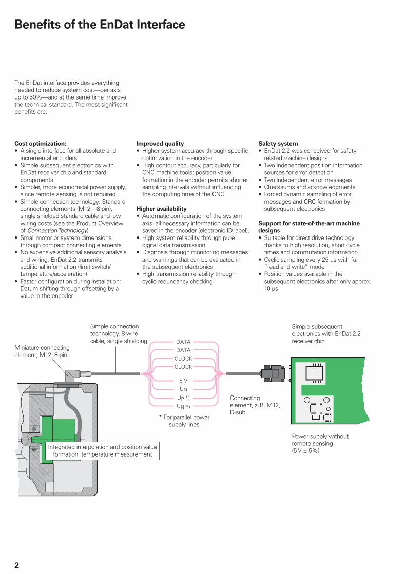
The EnDat interface provides everything needed to reduce system cost—per axis up to 50%—and at the same time improve the technical standard. The most signifi cant benefi ts are:
Cost optimization:
A single interface for all absolute and incremental encodersSimple subsequent electronics with EnDat receiver chip and standard componentsSimpler, more economical power supply, since remote sensing is not requiredSimple connection technology: Standard connecting elements (M12 – 8-pin), single shielded standard cable and low wiring costs (see the Product Overview of Connection Technology)Small motor or system dimensions through compact connecting elementsNo expensive additional sensory analysis and wiring: EnDat 2.2 transmits additional information (limit switch/temperature/acceleration)Faster confi guration during installation: Datum shifting through offsetting by a value in the encoder
•
•
•
•
•
•
•
Improved quality
Higher system accuracy through specifi c optimization in the encoderHigh contour accuracy, particularly for CNC machine tools: position value formation in the encoder permits shorter sampling intervals without infl uencing the computing time of the CNC
Higher availability
Automatic confi guration of the system axis: all necessary information can be saved in the encoder (electronic ID label).High system reliability through pure digital data transmissionDiagnosis through monitoring messages and warnings that can be evaluated in the subsequent electronicsHigh transmission reliability through cyclic redundancy checking
•
•
•
•
•
•
Safety system
EnDat 2.2 was conceived for safety-related machine designsTwo independent position information sources for error detectionTwo independent error messagesChecksums and acknowledgmentsForced dynamic sampling of error messages and CRC formation by subsequent electronics
Support for state-of-the-art machine
designs
Suitable for direct drive technology thanks to high resolution, short cycle times and commutation informationCyclic sampling every 25 µs with full “read and write” modePosition values available in the subsequent electronics after only approx. 10 µs
•
•
•••
•
•
•
Miniature connecting element, M12, 8-pin
Simple connection technology, 8-wire cable, single shielding
Integrated interpolation and position value formation, temperature measurement
Connecting element, z.B. M12, D-sub
Power supply without remote sensing (5 V ± 5%)
Simple subsequent electronics with EnDat 2.2 receiver chip
* For parallel power supply lines
Benefi ts of the EnDat Interface

3
The extended EnDat interface version 2.2 is compatible in its communication, command set and time conditions with the previous version 2.1, but also offers signifi cant advantages. It makes it possible, for example, to transfer additional information with the position value without sending a separate request for it. The interface protocol was expanded and the time conditions were optimized as follows:
Increased clock frequency (CLOCK) (16 MHz)Optimized calculating time (position value acquisition within 5 µs)Minimized dead time (recovery time) (1.25 to 3.75 µs)Expanded power supply range (3.6 V to 5.25 V or 14 V at the encoder)
•
•
•
•
EnDat 2.2 command set (includes EnDat 2.1 command set)
• Position values for incremental and absolute encoders • Additional information on position value ’ Diagnostics, test values ’ Absolute position values after reference run of incremental encoders ’ Send and receive parameters ’ Commutation ’ Acceleration ’ Limit position signal
EnDat 2.1 command set
• Absolute position values • Send and receive parameters • Reset • Test command • Test values
The EnDat interface transmits position values or additional physical quantities in an unambiguous time sequence and serves to read out from and write to the encoder’s internal memory.
1. Position values can be transmitted with or without additional information. The additional information types are selectable via the Memory Range Select (MRS) code. Other functions such as parameter reading and writing can also be called after the memory area has been selected. Through simultaneous transmission with the position value, additional information can also be requested of axes in the feedback loop, and functions executed with them.
2. Parameter reading and writing is possible both as a separate function and in connection with the position value. Parameters can be read or written after the memory area is selected.
3. Reset functions serve to reset the encoder in case of malfunction. Reset is possible instead of or during position value transmission.
4. Test commands and values are used for forced dynamic sampling in safety-related controls. The signifi cance of the error message is inverted in order to monitor its generation.
Compatibility of EnDat 2.2 > 2.1
Description of Function

������������������� ���� ������
��� � �
� ����� � � � � ��� ��� ��� ���
�� ��
� � ���� � � � �
� � � � � �
�� �
�
� � � ��� ��� ��� ���
4
A clock pulse (CLOCK) is transmitted by the subsequent electronics to synchronize data transmission. When not transmitting, the clock signal is on high level.
Clock frequency and cable length
Without propagation-delay compensation, the clock frequency—depending on the cable length—is variable between 100 kHz and 2 MHz. Because large cable lengths and high clock frequencies increase the signal run time to the point that they can disturb the unambiguous assignment of data, the delay can be measured in a test run and then compensated. With this propagation-delay compensation in the subsequent electronics, clock frequencies up to 16 MHz at cable lengths up to a maximum of 100 m (fCLK † 8 MHz) are possible. The maximum clock frequency is mainly determined by the cables and connecting elements used. To ensure proper function at clock frequencies above 2 MHz, use only original HEIDENHAIN cables.
The permissible clock frequencies shown in the diagrams apply for a clock on-off
ratio of 1:1. This means that the HIGH and LOW levels of the clock are equally long.For other on-off ratios, the theoretical clock frequency is calculated as fc = .
Determining the propagation time
After every change in the transmission line hardware, the propagation time must be ascertained—preferably automatically after every power interruption.
The subsequent electronics transmit the mode command Encoder transmit position values without additional information to the encoder. After the encoder has switched to transmission, i.e. after in total 10 clock periods, a counter in the subsequent electronics starts with every rising edge. The subsequent electronics measure the propagation time as the difference
Clock frequency
Clock frequency [kHz]
Cab
le len
gth
[m
]
Without delay compensationWith delay compensation
Clock on-off ratio
Clock
between the last rising clock pulse edge and the edge of the start bit. The process should be repeated at least three times in order to rule out any disturbances during the calculation of the propagation time and to test the value for consistency. The signal propagation time is measured at a reduced clock frequency (100 kHz to 200 kHz). To attain suffi cient accuracy, however, the
value must be sampled at an internal frequency that is at least eight times higher than the clock frequency to be used later for data transmission.
12tmin
Clock pulse transmitted to the encoder
Clock pulse at encoder
Data at encoder
Start counter
Data at subs. electronics
Mode
Mode command
Clock frequency 100 kHz to 200 kHz
S = start, F1 = error, D = data
Data Transfer

5
Transmitted data are identifi ed as either position values, position values with additional information, or parameters. The type of information to be transmitted is selected by mode commands. Mode
commands defi ne the content of the transmitted information. Every mode command consists of three bits. To ensure reliable transmission, every bit is transmitted redundantly (inverted or redundant). If the encoder detects an incorrect mode transmission, it transmits an error message. The EnDat 2.2 interface can also transfer parameter values in the additional information together with the position value. This makes the current position values constantly available for the control loop, even during a parameter request.
Mode bit
No. Mode command M2 M1 M0 (M2) (M1) (M0)
1 Encoder transmit position values
En
Dat
2.1
co
mm
an
d s
et
En
Dat
2.2
co
mm
an
d s
et
0 0 0 1 1 1
2 Selection of memory area 0 0 1 1 1 0
3 Encoder receive parameters 0 1 1 1 0 0
4 Encoder transmit parameters 1 0 0 0 1 1
5 Encoder receive reset1) 1 0 1 0 1 0
6 Encoder transmit test values 0 1 0 1 0 1
7 Encoder receive test command 1 1 0 0 0 1
8 Encoder transmit position value with addi-tional information
1 1 1 0 0 0
9 Encoder transmit position value and receive selection of memory area2)
0 0 1 0 0 1
10 Encoder transmit position value and receive parameters2)
0 1 1 0 1 1
11 Encoder transmit position value and transmit parameters2)
1 0 0 1 0 0
12 Encoder transmit position value and receive error reset2)
1 0 1 1 0 1
13 Encoder transmit position value and receive test command2)
1 1 0 1 1 0
14 Encoder receive communication command3) 0 1 0 0 1 0
1) Same reaction as switching the power supply off and on2) Selected additional information is also transmitted3) Reserved for encoders that do not support the safety system
The time absolute linear encoders need for calculating the position values tcal differs depending on whether EnDat 2.1 or EnDat 2.2 mode commands are transmitted (see Specifi cations in the Linear Encoders for Numerically Controlled Machine Tools brochure). If the incremental signals are evaluated for axis control, then the EnDat 2.1 mode commands should be used. Only in this manner can an active error message be transmitted synchronously with the currently requested position value. EnDat 2.1 mode commands should not be used for pure serial position value transfer for axis control.
Selecting the transmission type

���
� �
��
� �� ��
� �
6
One data packet is sent in synchronism per data transmission. The transmission cycle begins with the fi rst falling clock edge. The measured values are saved and the position value is calculated.
After two clock pulses (2T), the subsequent electronics transmits the mode command Encoder transmit position value (with/without additional information).After successful calculation of the absolute position value (tcal—see table), the start
bit begins the data transmission from the encoder to the subsequent electronics.The subsequent error bits, error 1 and
error 2 (only with EnDat 2.2 commands), are group signals for all monitored functions and serve for failure monitoring. They are generated separately from each other and indicate when a malfunction of the encoder can result in incorrect position values. The exact cause of the disturbance is saved in the “operating status” memory and can be interrogated in detail.
The encoder then transmits the absolute
position value, beginning with the LSB. Its length varies depending on which encoder is being used. The number of required clock pulses for transmission of a position value is saved in the parameters of the encoder manufacturer.
The data transmission of the position value is completed with the Cyclic Redundancy
Check (CRC). This is followed in EnDat 2.2 by the additional information 1 and 2, each also concluded with a CRC. The content of the additional information is determined by the selection of the memory area and is transmitted in the next sampling cycle for additional information. This information is then transmitted with every sampling until a selection of a new memory area changes the content.
With the end of the data word, the clock must be set to HIGH. After 10 to 30 µs or 1.25 to 3.75 µs (with EnDat 2.2 parameterizable recovery time tm) the data line falls back to LOW. Then a new data transmission can begin by starting the clock.
Position value packet without additional information
Encoder saves position value
Subsequent electronics transmit mode command
Mode command Position value CRC
S = start, F1 = error 1, F2 = error 2, L = LSB, M = MSBDiagram does not depict the propagation-delay compensation
Without delay compensation With delay compensation
Clock frequency fc 100 kHz ... 2 MHz 100 kHz ... 16 MHz
Calculation time for
Position value
Parameters
tcaltac Typical of EnDat 2.2 encoders: † 5 µs
Max. 12 ms
Recovery time tm EnDat 2.1: 10 to 30 µsEnDat 2.2: 10 to 30 µs or 1.25 to 3.75 µs (fc ‡ 1 MHz) (parameterizable)
tR Max. 500 ns
tST – 2 to 10 µs
Data delay time tD (0.2 + 0.01 x cable length in m) µs
Pulse width tHI
tLO
0.2 to 10 µs
0.2 to 50 msto 30 µs (with LC)
Pulse width fl uctuation HIGH to LOW max. 10%
Position Values

��� �
� �
��
�
� �� ��
���������
7
Data packet with position value and additional information 1 and 2
Encoder saves position value
Subsequent electronics transmit mode command
Mode command Position value CRC Additional information 2
Additional information 1
CRC CRC
S = start, F1 = error 1, F2 = error 2, L = LSB, M = MSB
Diagram does not depict the propagation-delay compensation
Typical command sequence when transmitting a position value with additional information:
Content of the data packet
Error messages 1 and 2
The EnDat interface enables comprehensive monitoring of the encoder without requiring an additional transmission line. An error message becomes active if a malfunction of the encoder might result in incorrect position values. At the same time, the cause of error is saved in the encoder. Errors include:
Light unit failureSignal amplitude too lowError in calculation of position valuePower supply too high/lowCurrent consumption is excessive
For reasons of security it is necessary to generate a second, independently acquired error message. This is transmitted with inverted level as error message 2.
Position value
The position value is transmitted as a complete data word whose length depends on the resolution of the encoder. Transmission begins with the LSB (LSB fi rst).
•••••
Additional information
One or two additional data can be appended to the position value, depending on the type of transmission (selection via MRS code). The additional data are each 30 bits in length, with LOW as fi rst bit. Each additional data is concluded with a CRC that is formed from the respective
additional information without the fi rst bit or the CRC.The additional information supported by the respective encoder is saved in the encoder parameters. The additional information includes status information, addresses, and data.
30 bits
Additional information 5 bitsCRC
Information (content)
8 bits address or data+ 8 bits data
Subsequent
electronics
transmit
Encoder
transmits
Subsequent
electronics
transmit
Encoder transmit position value and receive selection of memory area (selection of the desired additional information)
Mode command 001 001
▲ Position value ▲ MRS Random content
Encoder transmit position value and receive selection of memory area (acknowledgment of the MRS code)
Mode command 001 001 ▲
Position value
▲
01000111Acknowledg-ment request for MRS code
Random content
Encoder transmit position value with additional information (acknowledgment)
Mode command 111 000
▲ Position value Additional information 1MRS acknowledgment

8
Status data
WRN – Warnings
This collective bit indicates whether certain tolerance limits of the encoder have been reached or exceeded, for example rotational speed or light source control reserve, without necessarily indicating an incorrect position value. This function makes it possible to issue preventive warnings in order to minimize idle time. The cause of the warning is stored in the encoder memory. The alarms and warnings supported by the respective encoder are saved in the "parameters of the encoder manufacturer" memory area.
RM – Reference mark
The RM bit indicates whether the reference run has been completed. In incremental systems, this is required in order to establish the absolute reference to the machine reference system. The absolute position value can then be read from the additional information 1. On absolute encoders the RM bit is always on HIGH.
Busy – Parameter request
When LOW, the busy bit indicates that a parameter request (read/write) is possible. If a request is being processed (HIGH), the encoder memory must not be accessed.
Content of the additional information
The content of the additional information is defi ned by the mode command for selection of a memory area. This content, updated with each clock pulse, is transmitted until there is a new request. The following contents are possible:
Additional information 1
Diagnosis
Cyclic information on encoder function and additional diagnostic values.Position value 2
For incremental encoders: Relative position information (counter starts from zero at switch-on). Absolute position value is only available after the reference marks have been traversed (RM bit HIGH).For absolute encoders: Second absolute position value for safety-related applications.Memory parameters
Parameters saved in the encoder can also be transmitted along with the position values. The request is defi ned via memory range selection, followed by the output of the parameters with the associated address.MRS code – Acknowledgment
Acknowledgment of the requested memory range selection
•
•
•
•
Test values
Test values serve for inspection purposes, in service diagnostics, for example.Temperature
Transmission of temperature in encoders with integrated evaluation of temperature sensors.Additional sensors
The EnDat 2.2 protocol enables the connection of 16 additional sensors (4-bit address). The sensor values increase by x+1 for each request. The associated sensor is identifi ed by the address supplied.
Additional information 2
Commutation
Incremental encoders provide "rough" position information for commutation in electric motors.Acceleration
If the encoder has additional sensor systems for acceleration measurement, it can transmit the results.Limit position signals
Limit position signals and homing information.Asynchronous position value
Position formed by oversampling between two "regular" requests.Operating status error sources
Detailed information about the cause of the present error message
•
•
•
•
•
•
•
•
MRS code for selecting the additional information
C7 C6 C5 C4 C3 C2 C1 C0 Additional
information 1
0 1 0 0 0 0 0 0 Transmit additional information 1 without data content (NOP)0 1 0 0 0 0 0 1 Transmit diagnosis0 1 0 0 0 0 1 0 Transmit position values 2 word 1 LSB0 1 0 0 0 0 1 1 Transmit position values 2 word 20 1 0 0 0 1 0 0 Transmit position values 2 word 3 MSB0 1 0 0 0 1 0 1 Acknowledge memory content LSB0 1 0 0 0 1 1 0 Acknowledge memory content MSB0 1 0 0 0 1 1 1 Acknowledge MRS code0 1 0 0 1 0 0 0 Acknowledge test command0 1 0 0 1 0 0 1 Transmit test values word 1 LSB0 1 0 0 1 0 1 0 Transmit test values word 2 0 1 0 0 1 0 1 1 Transmit test values word 3 MSB0 1 0 0 1 1 0 0 Transmit temperature 10 1 0 0 1 1 0 1 Transmit temperature 20 1 0 0 1 1 1 0 Additional sensors0 1 0 0 1 1 1 1 Transmit no more additional information 1
Additional
information 2
0 1 0 1 0 0 0 0 Transmit additional information 2 without data content (NOP)0 1 0 1 0 0 0 1 Transmit commutation0 1 0 1 0 0 1 0 Transmit acceleration0 1 0 1 0 0 1 1 Transmit commutation and acceleration0 1 0 1 0 1 0 0 Transmit limit position signal0 1 0 1 0 1 0 1 Transmit limit position signal and acceleration0 1 0 1 0 1 1 0 Asynchronous position value word 1 LSB0 1 0 1 0 1 1 1 Asynchronous position value word 20 1 0 1 1 0 0 0 Asynchronous position value word 3 MSB0 1 0 1 1 0 0 1 Operating status error sources. . . . . . . . (Not used at present). . . . . . . .0 1 0 1 1 1 1 1 Transmit no more additional information 2

9
The encoder provides several memory areas for parameters. These can be read from by the subsequent electronics, and some can be written to by the encoder manufacturer, the OEM, or even the end user. Certain memory areas can be write-protected.
The parameters, which in most cases are set by the OEM, largely defi ne the function of the encoder and the EnDat interface. When the encoder is exchanged, it is therefore essential that its parameter settings are correct. Attempts to confi gure machines without including OEM data can result in malfunctions. If there is any doubt as to the correct parameter settings, the OEM should be consulted.
Absolute encoder Subsequent
electronics
Absolute posi-tion value
Operating parameters
Operating status
Parameters of the OEM
Parameters of the encoder manufacturer for
EnDat 2.1 EnDat 2.2
EnD
at in
terf
ace
Incremental signals *)
*) Depends on encoder
» 1 VPP A*)
» 1 VPP B*)
Block diagram of absolute encoder with EnDat 2.2 interface
Parameters of the encoder manufacturer
This write-protected memory area contains all information specifi c to the encoder, such as encoder type (linear/angular, singleturn/multiturn, etc.), signal periods, number of position values per revolution, transmission format of absolute position values, direction of rotation, maximum permissible speed, accuracy dependent on shaft speeds, support from warnings and alarms, ID number, and serial number. This information forms the basis for automatic
confi guration.
A separate memory area contains the parameters typical for EnDat 2.2: Status of additional information, temperature, acceleration, support of diagnostic and error messages, etc.
Parameters of the OEM
In this freely defi nable memory area, the OEM can store his information, e.g. the “electronic ID label” of the motor in which the encoder is integrated, indicating the motor model, maximum current rating, etc.
Operating parameters
This area is available to the customer for a datum shift and the confi guration of diagnostics. Furthermore, a warning threshold can be defi ned for the temperature sensor integrated in the encoder. Other functions (cycle time, I/0) are reserved for future applications. The operating parameter area can be protected against overwriting.
Operating status
This memory area provides detailed alarms or warnings for diagnostic purposes. Here it is also possible to initialize certain encoder functions, to activate write protection for the OEM parameter and operating parameter memory areas, and to interrogate their status.Once activated, the write protection
cannot be reversed.
Parameters
Memory areas

10
The meaning of the information contained in the parameters of the encoder manufacturer depends on the encoder.
HEIDENHAIN encoders can be divided into six groups. They are differentiated by the type of encoder (word 14 of the EnDat 2.1 parameters).
Encoder types:
L Linear encodersW Angle encoders (rotational)D Rotary encoders (rotational)E EIB external interface box for
conversion of 1 VPP to pure serial EnDat 2.2
iL Incremental linear encoder with integral conversion of 1 VPP to pure serial EnDat 2.2
iR Incremental rotational encoder with integral conversion of 1 VPP to pure serial EnDat 2.2
The meanings of parameters are divided into evaluation categories. On the basis of these categories, the user can make clear decisions on the use of parameters and their integration in the application software.
Evaluation categories:
Required:
It is essential for operation of the encoder that these parameters be considered.Depends on application:
Whether these parameters are to be considered depends on the customer's application. If, for example, no OEM range is used, then the parameter regarding memory allocation for parameters of the OEM need not be considered.Informative:
These parameters are not required for encoder operation, but they give the user additional information such as the model number.Not relevant:
If no encoder types were assigned to any of the three other evaluation categories, then the parameter is not required for encoder operation and can be ignored.
•
•
•
•
The additional information for EnDat 2.2 contained in the parameters of the encoder manufacturer depends in part on the respective encoder.
EnDat 2.2 parameters can be read out only with EnDat 2.2 mode commands.
The types of additional information, additional functions, diagnostic values, and specifi cations that the respective encoder supports are saved in the assigned status words of these memory areas. Before interrogation of the additional information, HEIDENHAIN recommends reading out the supported information and functions (typically for every initialization of encoders). They are also shown in the encoders' specifi cations.
Parameters of the encoder manufacturer
Parameters of the encoder manufacturer for EnDat 2.1
Unit for
Req
uir
ed
Dep
en
ds o
n
ap
plicati
on
Info
rmati
ve
Word Content Linear
encoder
Rotary/
Angle
encoder
Remark
4 Mask 0 – – – – – –
5 Mask 1 – – – – – –
6 Mask 2 – – – – – –
7 Mask 3 – – – – – –
8 Version of the EnDat interface – – – – All “2” saved with EnDat 2.1 or 2.2
9 Memory allocation for parameters of the OEM
– –All
– – Depends on encoder; program fl exibly. Memory pointer to fi rst free address10
11 Memory allocation for compensation values
– – – – – Reserved for encoder manufacturer
12
13 Number of clock pulses for transfer of position value (transmission format)
– – All – – Setting the correct clock number for po-sition transmission
14 Type of encoder – – All – – Defi nes the units of the parameters
15 Signal period(s) per revolution for incremental output signals
nm – All – – E, iL, iR: for calculating the smallest display step (LSB) or the correct display value for negative traverse directionAll: for EnDat-compliant datum shift
16
17 Distinguishable revolutions (only for multiturn encoders)
– – W D – – Required for correct calculation of the position
18 (Nominal) increment of reference marks
mm Signal periods – – E iL iR –
19 Position of fi rst reference mark mm – – – iL Not supported by EIB

11
Parameters of the encoder manufacturer for EnDat 2.1 (continued)
Unit for
Req
uir
ed
Dep
en
ds o
n
ap
plicati
on
Info
rmati
ve
Word Content Linear
encoder
Rotary/
Angle
encoder
Remark
20 Measuring step or steps per revolution with serial data transmission
nm Measuring steps per revolution
All – – –
21
22 Datum shift of the encoder manufacturer
Signal periods Signal periods All – – To be accounted for by the user for da-tum shift23
24 ID number – – – – All Safety technology
25
26
27 Serial number – – – All – Encoder exchange can be detected (may affect application—safety related)28
29
30 Direction of rotation or traverse – – All – – –
31 Status of commissioning diagnosis – – – – – No longer supported since 1999
32 Maximum mechanically permissible linear velocity or shaft speed
m/min min–1 – W L D iL iR
– Required for cross checking of absolute position incremental position
33 Accuracy depending on linear velocity or shaft speed, Area I
LSB 1) LSB 1) – W L D – Comparison of absolute and incremental position not possible with E iL iR, because these encoders have only incremental information
34 Accuracy depending on linear velocity or shaft speed Area II
LSB 1) LSB 1) – W L D –
35 Support of error messages 1 – – All – – For defi nition of an “error mask” (safety related)
36 Support of warnings – – – – All For preventive maintenance
37 EnDat command set – – All – – Information whether EnDat 2.2 mode commands are supported
38 Reserved for measuring length 2) – – – – L iL Not supported by EIB.
39 Maximum processing time – – All – – For monitoring (time out)
40 EnDat ordering designation – – – All – Distinguishes between with/without incremental signals
41 HEIDENHAIN specifi cations – – – – – –
42
43
44
45
46
47 CHECKSUM – – – – – –1) The higher-valued byte contains the divisor with respect to the maximum permissible linear velocity or rotational shaft speed up to which this accuracy is valid.2) Not supported by all linear encoder models; initialized with default value 0.

12
Parameters of the encoder manufacturer for EnDat 2.2
Unit for
Word Content Linear
encoder
Rotary/
Angle
encoder
Req
uir
ed
Dep
en
ds o
n
ap
plicati
on
Info
rmati
ve
Remark
0 Status of additional information 1 – – – All – Can be safety related.Cross checking of “what is required” and “what does the encoder support”
1 Status of additional information 2 – – – All –
2 Status of additional functions – – – All –
3 Acceleration m/s2 1/s2 – All – Consider the scaling factor
4 Temperature K K – All – Consider the scaling factor
5 Diagnostic status – – – – All –
6 Support of error message 2 – – All – – For defi nition of an “error mask” (safety related)
7 Dynamic sampling status – – – All – Safety technology
8
9 Measuring step or measuring steps per revolution for position value 2
nm – – All – Safety technology or EIB, iL, iR
10
11 Accuracy of position value 2 depending on linear velocity or shaft speed, Area I
LSB1) LSB1) – All – Safety technology or EIB, iL, iR
12 LSB1) LSB1) – All – Safety technology or EIB, iL, iR
13 Accuracy of position value 2 depending on linear velocity or shaft speed, Area II
LSB 1) LSB 1) – All – Safety technology or EIB, iL, iR
14 LSB 1) LSB 1) – All – Safety technology or EIB, iL, iR
15 Distinguishable revolutions Position value 2 (only for multiturn encoders)
– – W D – – Required for correct calculation of the position
16 Direction of rotation of position value 2 – – All – – –
17 to 20
Encoder designation – – – – All –
21 Support of instructions – – – – – Not yet supported.Not for safety technology
22 Max. permissible encoder temperature at measuring point
K K – W L D iL iR
– Not supported by EIB
23 Max. permissible acceleration m/s2 1/s2 – W L D iL iR
– Not supported by EIB
24 Number of blocks for memory area Section 2
– – All – – Depends on encoder; program fl exibly
25 Maximum clock frequency kHz kHz All – – Depends on connector, cable lengths
26 Number of bits for position comparison – – – All – Safety technology
27 Scaling factor for resolution – – All – – For calculation of the smallest display step (LSB).28 Measuring step, or measuring steps
per revolution or subdivision values of a grating period
– –All
– –
29
30 Max. velocity or rotational shaft speed for constant code value
m/min min–1 – W L D iL iR
– Specifi c to application. Applies for encoders that permit higher mechanical than electrical speed. Not supported by the EIB
31 Offset between position value and position value 2
– – – All – Safety technology
32
33
34 “Number of distinguishable revolutions” with scaling factor
– – W D – – Required for correct calculation of the position
35 Support of operating status error sources
– – – All – Expanded EnDat error message, particularly for battery-buffered encoders
63 CHECKSUM – – – – – –
1) The higher-valued byte contains the divisor with respect to the maximum permissible linear velocity or rotational shaft speed up to which this accuracy is valid.

�������
!�"�� "
�������
��
13
Control cycles for transfer of parameters
(EnDat 2.1 mode command 001110)
Before parameter transfer, the memory area is specifi ed with the selection of memory area mode command. The possible memory areas are stored in the parameters of the encoder manufacturer. Due to internal access times to the individual memory areas, the time tac may reach 12 ms.
Reading parameters from the encoder
(EnDat 2.1 mode command 100011)
After selecting the memory area, the subsequent electronics transmit a complete communications protocol beginning with the mode command Encoder transmit parameters, followed by an 8-bit address and 16 bits with random content. The encoder responds with the repetition of the address and 16 bits with the contents of the parameter. The transmission cycle is concluded with a CRC check.
Writing parameters to the encoder
(EnDat 2.1 mode command 011100)
After selecting the memory area, the subsequent electronics transmit a complete communications protocol beginning with the mode command Encoder receive parameters, followed by an 8-bit address and a 16-bit parameter value. The encoder answers by repeating the address and the contents of the parameter. The CRC check concludes the cycle.
Transmitter in encoder inactive
Receiver in encoder active
Transmitter in encoder active
Address
Address
Address
Address
8 bits 16 bits 8 bits 16 bits
x = random y = parameter Acknowledgment
Typical EnDat 2.2 command sequence for transmitting a position value with parameter values in the additional information
(max. 12 ms access time by interrogating the integrated EEPROM)
Subsequent elec-
tronics transmit
Encoder
transmits
Subsequent electronics
transmit
Encoder transmit position value and receive selection of memory area (selection of the desired additional information)
Mode command 001 001
▲ Position value
▲ MRS Random content
Encoder transmit position value and receive selection of memory area (acknowledgment of the MRS code)
Mode command 001 001 ▲
Position value
▲
01000111Acknowledg-ment request for MRS code
Random content
Encoder transmit position value with additional information (acknowledgment)
Mode command 111 000
▲ Position value
Additional information 1MRS acknowledgment
▲
Encoder transmit position value and transmit parameters
Mode command 100 100
▲ Position value
▲ Address Random content
Encoder transmit position value with additional information
Mode command 111 000
▲ Position value
Additional information 1Busy = 1/no data
▲
Parameter value is not yet available, therefore the busy bit is at 1.
Encoder transmit position value with additional information
Mode command 111 000
▲ Position value
Additional information 1Busy = 1/no data
▲
Encoder transmit position value with additional information
Mode command 111 000
Position value
Additional information 1Busy = 1/no data
▲
Max. 12 ms
Encoder transmit position value with additional information
Mode command 111 000
Position value
Additional information 1Busy = 0/parameter
▲
This concludes the request. A new parameter value can be requested from a new address.
Transmission of parameters

���������
14
Diagnosis
The EnDat interface makes extensive monitoring and diagnosis of an encoder possible without an additional line. The diagnostic system generates error messages and warnings (see Position values), and is a signifi cant prerequisite for the high level of availability of the complete system.
Online diagnostics are growing in signifi cance. Decisive points of emphasis are:
Machine usage planning Support for the service technician on-siteSimple evaluation of encoder function reservesSimplifi cation of trouble-shooting for repairGeneration of meaningful quality statistics
On encoders with incremental signals, it is possible to use Lissajous fi gures to analyze signal errors and what they mean for encoder function.
Encoders with pure serial interfaces do not provide incremental signals. Encoders with EnDat 2.2 can cyclically output the valuation numbers in order to evaluate the functions of the encoder. The valuation numbers provide the current state of the encoder and ascertain the encoder’s “functional reserves.” Their scaling is identical for all HEIDENHAIN encoders. This makes integrated evaluation possible. The valuation numbers supported by the respective encoder are saved in the EnDat 2.2 parameters.
Composition and interrogation of the transmitted diagnostics data:
The desired valuation numbers must be activated.The value (8 bits) is transmitted over the additional information 1.The values are output in a cyclic process; address and value.The information as to which valuation numbers are supported is saved in the EnDat 2.2 parameters.The diagnostics information can be transmitted in the closed-loop mode.The “border areas” should be suppressed in the display (defi nition of reserve areas is required).“Unknown addresses” (system data) must be ignored in the subsequent electronics.
•••
•
•
•
•
•
•
•
•
•
30 bits
Additional information 5 bitsCRC
Information (content)
8 bits for address + 8 bits for data
The valuation numbers in EnDat 2.2 are provided in the additional information.
Screen showing the valuation numbers as functional reserves (e.g. with IK 215)
Activation of diagnosis
Interrogation of diagnostics data “Encoder transmit position val-ue with additional information”
Adaptation of synchronism to a valid packet header. (non-supported addresses ƒ system data
must be suppressed)
Determination and display of valid valuation numbers
Flow chart for interrogation of diagnostics data

15
Function initialization
In word 3 of the operating status, the customer can defi ne the functions of data transmission or special function modes of the encoder.
In the default setting, all additional information data are deactivated and the recovery time is programmed at 10 µs † tm † 30 µs. Recovery time can be changed to 1.25 µs † tm † 3.75 µs only for the mode commands 8 to 14.
For clock pulse frequencies † 1 MHz, recovery time must remain set to 10 µs † tm † 30 µs.
The oversampling, diagnostics reset and EnDat-2.2 cyclic operation can be deactivated functions are reserved for future applications, and cannot yet be activated.
In the future, the multiturn functions will enable connection of battery-buffered encoders.
Information Condition upon delivery
Recovery time tm 10 µs † tm † 30 µsAdjustable to 1.25 µs † tm † 3.75 µs1)
Reference pulse initialization Deactivated
Oversampling Deactivated
EnDat 2.2 cyclic operation can be deactivated
Activated
Multiturn overfl ow alarm Deactivated
Multiturn overfl ow latch Deactivated
Multiturn position alarm Deactivated
Multiturn counter reset Deactivated
Diagnostics reset Deactivated
1) Valid only for the mode commands 8 to 14 of the EnDat 2.2 command set
Confi guration of diagnosis
In word 3 of the operating status, the customer can defi ne the confi guration of the diagnosis for the “Encoder transmit position values with additional information mode” command.
Recommendation: All available valuation numbers should be activated to ensure the maximum depth of information on the encoder's function reserves.
= 0 = 1
Valuation number 1 Deactivated Activated
Valuation number 2 Deactivated Activated
Valuation number 3 Deactivated Activated
Valuation number 4 Deactivated Activated
System-specifi c data Deactivated Activated
The confi guration is not activated until the encoder receive reset mode
command has been transmitted.
Confi guration

��
���������
�� �� ��
��#
16
Power supply
The encoders require a stabilized dc
voltage UP as power supply. The required power supply and the current consumption are given in the respective specifi cations. The values apply as measured at the encoder.
EnDat 2.2 encoders feature an expanded power supply range from 3.6 to 5.25 V or from 3.6 to 14 V. This makes it possible to design the power supply of the subsequent electronics so that the resulting voltage after attenuation through cable length, cable cross section and current consumption can be processed without correction (applies only for cable assemblies from HEIDENHAIN). This means that monitoring the voltage at the encoder with the encoder's sensor lines and adjusting the supply voltage through a controllable power supply (remote sense) are no longer necessary.
The permissible ripple content of the dc voltage is:
High frequency interferenceUPP < 250 mV with dU/dt > 5 V/µsLow frequency fundamental rippleUPP < 100 mV
Starting behavior at the encoder
The integrated electronics require an initialization time of approx. 1.3 s, whereby the initialization phase should be taken into account (see “Clock pulse sequence from the subsequent electronics” at right).
After conclusion of the initialization phase, a certain switch-on routine is necessary. Only EnDat 2.1 mode commands can be used for this purpose.
•
•
Power supply
from subsequent
electronics
(supply point)
see the Specifi cations of the encoder
Reaction of the
encoder
Clock pulse
sequence from
the subsequent
electronics
UP max.
UP min.
Start
ƒ undefi ned
Valid HIGH or LOW level
‡ 1 ms
At least one pulse (>125 ns) or one request cycle
† 50 ms
*) high-impedance
Interface
Power supply and switch-on
Encoder's initialization phase is concluded
Encoder reset“Encoder receive reset” mode command
Wait for 50 ms
Read out and buffering of alarms and warnings
Deletion of alarms
Deletion of warnings
Readout of “Number of pulses for transfer of position value.” (Parameters of the encoder manufacturer, word 13)
Inquiry whether the encoder supports EnDat 2.2 commands(Parameters of the encoder manufacturer, word 37)
Data
800 ms † t1 † any 80 ms † t2 † 120 ms380 ms † t3 † 420 ms
Clock

17
Data (measured values or parameters) can be transferred bidirectionally between position encoders and subsequent electronics with transceiver components in accordance with RS-485 (differential signals), in synchronism with the clock signal produced by the subsequent electronics.
Dimensioning
IC1 = RS 485 differential line receiver and driver
C3 = 330 pFZ0 = 120 −
Encoder Subsequent electronics
Input circuitry of the subsequent electronics
Data transfer
Incremental signals
Depends on encoder

18
Safety System
Complete safe servo drive system
Safety-related position measuring system
EnDat 2.2
EnDat master
Encoder
Power cable
Safe controlServo drive
Power stage
Basic principle
EnDat 2.2 supports the use of encoders in safety-related applications. The ISO 13 849-1 (previously EN 954-1) and IEC 61 508 standards serve as the foundation for this. These standards describe the assessment of safety-related systems, for example based on the failure probabilities of integrated components and subsystems.
The modular approach helps manufacturers of safety-related systems to implement their complete systems, because they can begin with prequalifi ed subsystems. Safety-related position encoders with pure serial data transmission via EnDat 2.2 accommodate this technique. The defi ned data interface to the subsequent electronics makes implementation in safety systems easier for the user.
In a safe drive, the safety-related position measuring system presents such a subsystem. The safety-related position
measuring system consists of:
Encoder with EnDat 2.2 transmission componentData transfer line with EnDat 2.2 communication and HEIDENHAIN cableEnDat 2.2 receiver component with monitoring function (EnDat master)
Integration of the position measuring
system
The position measuring system is integrated via a physical and an electrical interface into the complete system. The physical coupling of the encoder to the drive is determined by the encoder’s geometry. Including the EnDat master with its monitoring functions in the safe control ensures its electrical integration. The necessary measures have already been defi ned. The control manufacturer must only implement them. With regard to a safe complete system, the remaining components of the complete system must also be designed for safe technology.
•
•
•
Area of application
Safety-related position measuring systems from HEIDENHAIN are designed so that they can be used as single-encoder systems in applications with control category SIL-2 (in accordance with IEC 61 508). This corresponds to performance level “d” of ISO 13 849 or category 3 according to EN 954-1. Also, the functions of the safety-related position measuring system can be used for the following safety functions in the complete system (also see IEC 61 800-5-2):
Safe switch-offSafe stopSafe controlled stopSafe reduced linear velocitySafe reduced rotational speedSafe limited jog incrementSafe limited absolute position
•••••••
Function
The safety system of the position encoder is based on two mutually independent position values and additional error bits produced in the encoder and transmitted over the EnDat 2.2 protocol to the EnDat master. The EnDat master assumes various monitoring functions with which errors in the encoder and during transmission can be revealed. The two position values are then compared. The EnDat master then provides the two position values and mutually independent error bits to the safe control over two processor interfaces. The control monitors the correct operation of the safety-related position measuring system with periodic tests.
The architecture of the EnDat 2.2 protocol makes it possible to conduct all safety-oriented information or control mechanisms during unconstrained controller operation. The safety-related information is therefore saved in the additional information. According to IEC 61 508, the architecture of the position measuring system is regarded as a single-channel tested system.

19
Safety-related position measuring system
Measured value
acquisition
Data transmission line
Position values and error bits via two processor interfaces
Monitoring functions
Effi ciency test
Reception of measured values
Position 1
Position 2
(protocol and cable)
EnDat 2.2
Serial data transferTwo independent position values
Internal monitoring
Protocol formation
EnD
at in
terf
ace
EnDat master
Interface 1
Interface 2
Safe control
Catalog of measures
The EnDat 2.2 interface supports the following individual safety-relevant functions:
Two mutually independent position
values for error detection
In addition to the position value, the additional information includes a separately generated position value to be used for comparison in the subsequent electronics.
Two mutually independent error
messages
The error messages are generated independently of each other and are transmitted at different active levels.
Independent individual CRC generation
for position values and additional
information
Separate CRC values are generated for the individual data packets of a transmission (position value, additional information 1 and 2).
Highly dynamic data acquisition and
transmission
Short cycle times for data acquisition including transmission make the necessary position-value comparisons and monitoring of transmission functions possible.
Reliable position value acquisition requires that the subsequent electronics initiate these functions and evaluate the data correctly. More detailed information can be found in the "Safety-Related Position Measuring Systems" Technical Information and the package of measures for the safe control.

383 942-24 · 5 · 11/2008 · F&W · Printed in Germany
For more information:HEIDENHAIN encoder brochuresDescription of the master component (www.mazet.de)Detailed interface specifi cation (upon request)Product Overview: Connection Technology
••
•
•
EnDat is available in two versions, EnDat 2.1 and EnDat 2.2. Only EnDat 2.2 devices support functions such as short recovery time and additional information.
Absolute encoders Resolution
Linear encoders LC 183/LC 483 ± 5 µm ± 3 µmLIC 4000 ± 5 µm
0.01 µm0.005 µm0.01 µm
Angle encoders RCN 226RCN 228RCN 729/RCN 829
26 bits28 bits29 bits
Rotary encoders Optical, singleturnROC/ECN 425, ECN 1325, ECN 125ROC/ECN 10xx/11xxOptical, multiturnROQ/EQN 437, EQN 1337,ROQ/EQN 10xx/11xxInductive, singleturnECI 13xxECI 11xxInductive, multiturnEQI 13xxEQI 11xx
25 bits23 bits
37 bits35 bits
19 bits1)
18 bits1)
31 bits1)
30 bits1)
Incremental encoders Resolution
Encoders with 1-VPP output signals over EIB(External Interface Box)
Integrated 14-bit interpolation
1) EnDat 2.1 available, EnDat 2.2 planned.
Overview of Encoders
333 E. State ParkwaySchaumburg, IL 60173-5337877-920-2703www.heidenhain.us


![2.13 Servo control - gregbotos.comgregbotos.com/publicfiles/siemens_data/Sinamics... · the position sensing, encoder n [4704.8] [4704.5] Position value 2 from encoder n The contents](https://img.pdfslide.net/doc/110x75/5f1da6eb6648ad757961c989/213-servo-control-the-position-sensing-encoder-n-47048-47045-position.jpg)