Embed Size (px)
Citation preview
® Specif icat ion Submittal page
Job Name:
Job Number:
Model Numbers:
Energi Savr NodeT QSNE Switching / 0-10 V Fixture Controller
369-261d 1 02.09.12
Energi Savr NodeT
The Energi Savr NodeT family is a group of modular products for the control of lighting loads. This document describes the following products:
•EnergiSavrNodeT for 0-10 V/Switching (model QSNE-4T10-D)
•EnergiSavrNodeT for Switching only (model QSNE-4S10-D)
Features•Defaultconfigurationrequiresnocommissioning.•Systemprogrammingaccomplishedmanuallyattheunit.•Twooccupancysensorinputsforautomatedcontrolof
lights in areas.•Twodaylightsensorinputsautomaticallyadjustlightlevels
based on the amount of natural light entering through the windows.
•TwoIRreceiverinputsforpersonalcontrol.•IncludesQSlinkforseamlessintegrationoflights, motorizedwindowtreatments,andcontrolstations.
•EnergiSavrNodeT units can be used in a QuantumR system to control and manage light in an entire building.
N1771Z096
QSNE-4T10-D
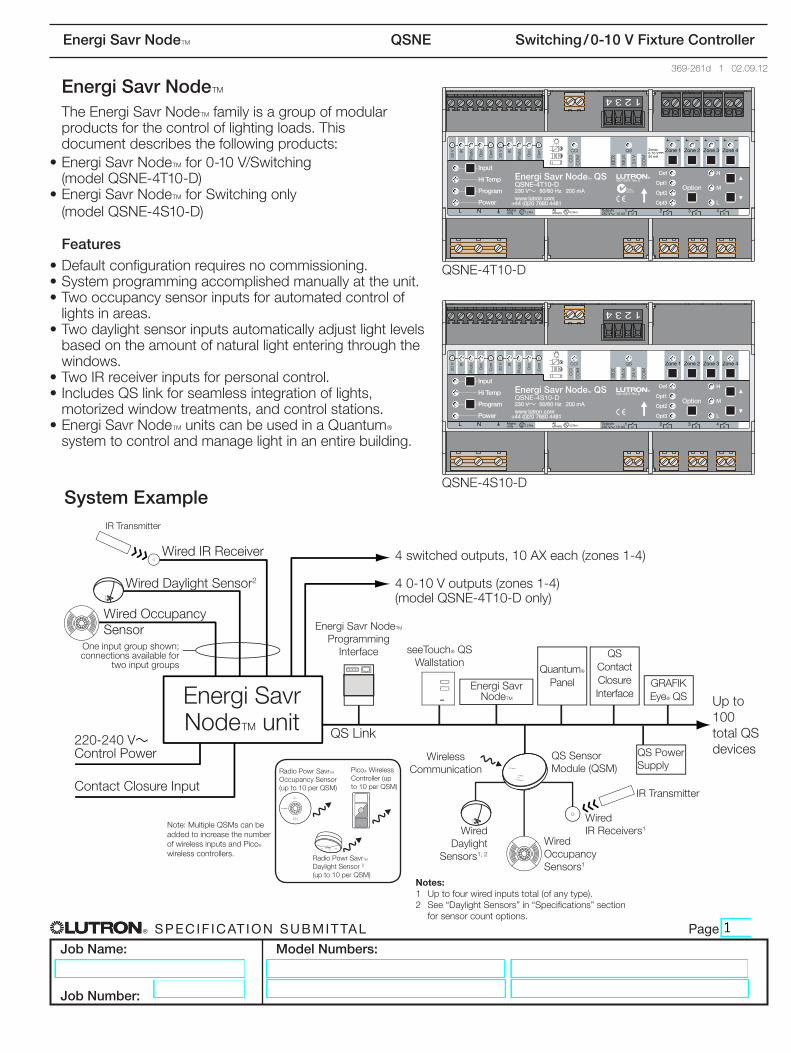
QSNE-4S10-DSystem Example
LUTRON
LUTR
ON
R
LUTRON
LUTR
ON
R
QSLink
Energi Savr NodeTEnergi Savr
NodeT unit
GRAFIKEyeR QS
QS Contact Closure Interface
QuantumR Panel
Energi Savr NodeT Programming
Interface seeTouchR QS Wallstation
WiredIRReceiver
IRTransmitter
Wired Daylight Sensor2
Wired Occupancy Sensor
ContactClosureInput
Up to 100 total QS devices
220-240 V~ Control Power
One input group shown; connections available for
two input groups
Wireless Communication
QS Sensor Module (QSM)
QS Power Supply
RadioPowrSavrT Occupancy Sensor (up to 10 per QSM)
RadioPowrSavrT Daylight Sensor 2 (up to 10 per QSM)
PicoR Wireless Controller (up to 10 per QSM)
Wired Daylight
Sensors1,2
Wired Occupancy Sensors1
Wired IRReceivers1Note: Multiple QSMs can be
added to increase the number of wireless inputs and PicoR wireless controllers.
4switchedoutputs,10AXeach(zones1-4)
4 0-10 V outputs (zones 1-4) (model QSNE-4T10-D only)
Notes: 1 Up to four wired inputs total (of any type).2 See“DaylightSensors”in“Specifications”section
for sensor count options.
IRTransmitter
® Specif icat ion Submittal page
Job Name:
Job Number:
Model Numbers:
Energi Savr NodeT QSNE Switching / 0-10 V Fixture Controller
369-261d 2 02.09.12
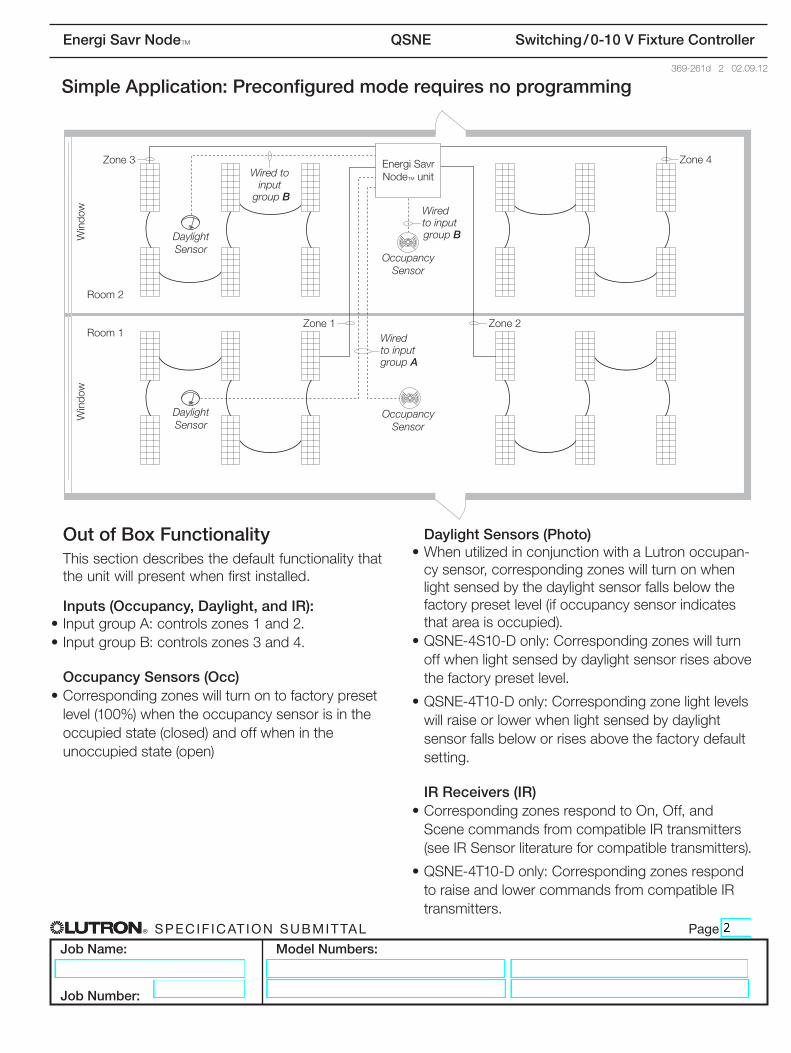
Simple Application: Preconfigured mode requires no programming
Out of Box FunctionalityThis section describes the default functionality that the unit will present when first installed.
Inputs (Occupancy, Daylight, and IR):•InputgroupA:controlszones1and2.•InputgroupB:controlszones3and4.
Occupancy Sensors (Occ)•Correspondingzoneswillturnontofactorypreset
level (100%) when the occupancy sensor is in the occupied state (closed) and off when in the unoccupied state (open)
Daylight Sensors (Photo)•WhenutilizedinconjunctionwithaLutronoccupan-cysensor,correspondingzoneswillturnonwhenlight sensed by the daylight sensor falls below the factory preset level (if occupancy sensor indicates that area is occupied).
•QSNE-4S10-Donly:Correspondingzoneswillturnoff when light sensed by daylight sensor rises above the factory preset level.
•QSNE-4T10-Donly:Correspondingzonelightlevelswill raise or lower when light sensed by daylight sensor falls below or rises above the factory default setting.
IR Receivers (IR)•CorrespondingzonesrespondtoOn,Off,andScenecommandsfromcompatibleIRtransmitters(seeIRSensorliteratureforcompatibletransmitters).
•QSNE-4T10-Donly:CorrespondingzonesrespondtoraiseandlowercommandsfromcompatibleIRtransmitters.
OccupancySensor
Zone 1Wired to sensor group A
Zone 3
Room 2
Room 1
Win
dow
Win
dow
Zone 2
OccupancySensor
Wired to sensor group B
Wired to sensor group BDaylight
Sensor
LUTRON
DaylightSensor
LUTRON
Zone 4 Energi Savr Node QS
Energi Savr NodeT unit
Occupancy Sensor
Daylight Sensor
Daylight Sensor
Zone3
Zone 1Room1
Room2
Win
dow
Win
dow
Zone 2
Zone 4
Occupancy Sensor
Wired to input
group BWired to input group B
Wired to input group A
® Specif icat ion Submittal page
Job Name:
Job Number:
Model Numbers:
Energi Savr NodeT QSNE Switching / 0-10 V Fixture Controller
369-261d 3 02.09.12
Out of Box Functionality (continued)
seeTouchR QS Wallstations•AllseeTouchR QS lighting wallstations are Scene keypadsbydefault.
•QSNE-4S10-Donly:Scenes1-16willturnallthelights On.
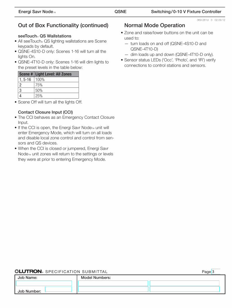
•QSNE-4T10-Donly:Scenes1-16willdim lights to the preset levels in the table below:
Scene # Light Level: All Zones1, 5-16 100%2 75%3 50%4 25%
•SceneOffwillturnallthelightsOff.
Contact Closure Input (CCI)•TheCCIbehavesasanEmergencyContactClosureInput.
•IftheCCIisopen,theEnergiSavrNodeT unit will enterEmergencyMode,whichwillturnonallloadsand disable local zone control and control from sen-sors and QS devices.
•WhentheCCIisclosedorjumpered,EnergiSavrNodeT unit zones will return to the settings or levels they were at prior to entering Emergency Mode.
Normal Mode Operation•Zoneandraise/lowerbuttonsontheunitcanbe
used to: — turn loads on and off (QSNE-4S10-D and
QSNE-4T10-D) — dim loads up and down (QSNE-4T10-D only).•SensorstatusLEDs(‘Occ’,‘Photo’,and‘IR’)verify
connections to control stations and sensors.
® Specif icat ion Submittal page
Job Name:
Job Number:
Model Numbers:
Energi Savr NodeT QSNE Switching / 0-10 V Fixture Controller
369-261d 4 02.09.12
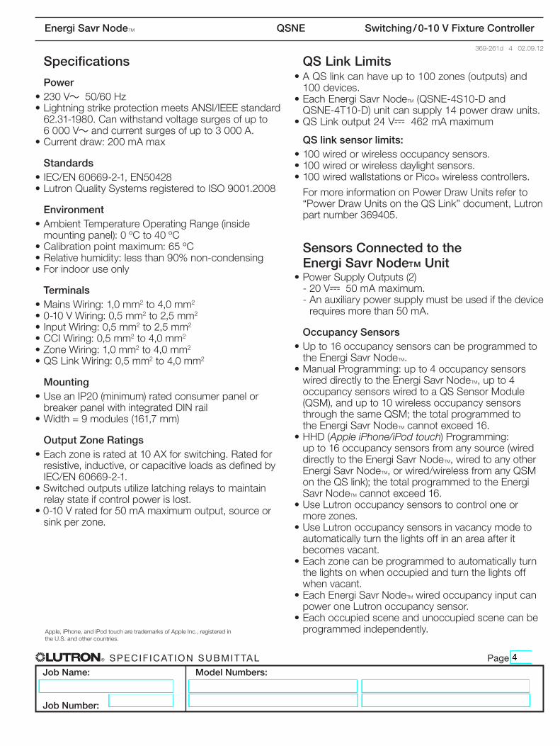
Specifications
Power•230V~50/60Hz•LightningstrikeprotectionmeetsANSI/IEEEstandard62.31-1980.Canwithstandvoltagesurgesofupto 6000V~andcurrentsurgesofupto3000A.
•Currentdraw:200mAmax
Standards•IEC/EN60669-2-1,EN50428•LutronQualitySystemsregisteredtoISO9001.2008
Environment•AmbientTemperatureOperatingRange(inside
mounting panel): 0 ºC to 40 ºC•Calibrationpointmaximum:65ºC•Relativehumidity:lessthan90%non-condensing•Forindooruseonly
Terminals•MainsWiring:1,0mm2to4,0mm2
•0-10VWiring:0,5mm2to2,5mm2
•InputWiring:0,5mm2to2,5mm2
•CCIWiring:0,5mm2to4,0mm2
•ZoneWiring:1,0mm2to4,0mm2
•QSLinkWiring:0,5mm2to4,0mm2
Mounting•UseanIP20(minimum)ratedconsumerpanelorbreakerpanelwithintegratedDINrail
•Width=9modules(161,7mm)
Output Zone Ratings•Eachzoneisratedat10AXforswitching.Ratedforresistive,inductive,orcapacitiveloadsasdefinedbyIEC/EN60669-2-1.
•Switchedoutputsutilizelatchingrelaystomaintainrelay state if control power is lost.
•0-10Vratedfor50mAmaximumoutput,sourceorsinkperzone.
QS Link Limits•AQSlinkcanhaveupto100zones(outputs)and
100 devices. •Each Energi Savr NodeT (QSNE-4S10-D and
QSNE-4T10-D) unit can supply 14 power draw units.•QSLinkoutput24V-462mAmaximum
QS link sensor limits:•100wiredorwirelessoccupancysensors.•100wiredorwirelessdaylightsensors.•100wiredwallstationsorPicoR wireless controllers.
FormoreinformationonPowerDrawUnitsreferto“PowerDrawUnitsontheQSLink”document,Lutronpartnumber369405.
Sensors Connected to the Energi Savr Node™ Unit
•PowerSupplyOutputs(2) - 20 V-50mAmaximum. -Anauxiliarypowersupplymustbeusedifthedevice
requiresmorethan50mA.
Occupancy Sensors•Upto16occupancysensorscanbeprogrammedto
the Energi Savr NodeT.•ManualProgramming:upto4occupancysensors
wired directly to the Energi Savr NodeT,upto4 occupancy sensors wired to a QS Sensor Module (QSM),andupto10wirelessoccupancysensorsthrough the same QSM; the total programmed to the Energi Savr NodeTcannotexceed16.
•HHD(Apple iPhone/iPod touch) Programming: upto16occupancysensorsfromanysource(wireddirectly to the Energi Savr NodeT,wiredtoanyotherEnergi Savr NodeT,orwired/wirelessfromanyQSMontheQSlink);thetotalprogrammedtotheEnergiSavr NodeTcannotexceed16.
•UseLutronoccupancysensorstocontroloneor more zones.
•UseLutronoccupancysensorsinvacancymodetoautomatically turn the lights off in an area after it becomes vacant.
•Eachzonecanbeprogrammedtoautomaticallyturnthe lights on when occupied and turn the lights off when vacant.
•EachEnergiSavrNodeT wired occupancy input can power one Lutron occupancy sensor.
•Eachoccupiedsceneandunoccupiedscenecanbeprogrammed independently.Apple,iPhone,andiPodtoucharetrademarksofAppleInc.,registeredin
the U.S. and other countries.
® Specif icat ion Submittal page
Job Name:
Job Number:
Model Numbers:
Energi Savr NodeT QSNE Switching / 0-10 V Fixture Controller
369-261d 5 02.09.12
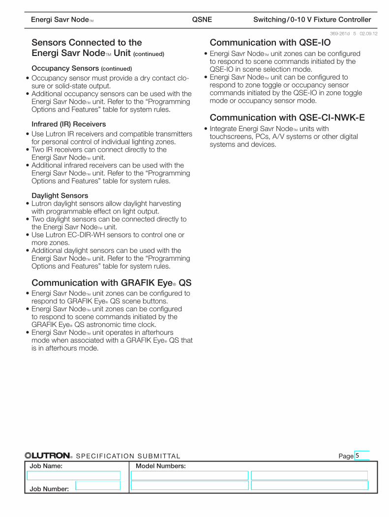
Sensors Connected to the Energi Savr NodeT Unit (continued)
Occupancy Sensors (continued)
•Occupancysensormustprovideadrycontactclo-sure or solid-state output.
•AdditionaloccupancysensorscanbeusedwiththeEnergi Savr NodeT unit.Refertothe“Programming OptionsandFeatures” table for system rules.
Infrared (IR) Receivers•UseLutronIRreceiversandcompatibletransmitters
for personal control of individual lighting zones.•TwoIRreceiverscanconnectdirectlytothe
Energi Savr NodeT unit.•Additionalinfraredreceiverscanbeusedwiththe
Energi Savr NodeTunit.Refertothe“Programming OptionsandFeatures” table for system rules.
Daylight Sensors•Lutrondaylightsensorsallowdaylightharvesting
with programmable effect on light output.•Twodaylightsensorscanbeconnecteddirectlyto
the Energi Savr NodeT unit.•UseLutronEC-DIR-WHsensorstocontroloneor
more zones.•Additionaldaylightsensorscanbeusedwiththe
Energi Savr NodeTunit.Refertothe“ProgrammingOptionsandFeatures”tableforsystemrules.
Communication with GRAFIK EyeR QS•EnergiSavrNodeTunitzonescanbeconfiguredtorespondtoGRAFIKEyeR QS scene buttons.
•EnergiSavrNodeT unitzonescanbeconfiguredto respond to scene commands initiated by the GRAFIKEyeR QSastronomictimeclock.
•EnergiSavrNodeT unit operates in afterhours modewhenassociatedwithaGRAFIKEyeR QS that is in afterhours mode.
Communication with QSE-IO•EnergiSavrNodeTunitzonescanbeconfigured
to respond to scene commands initiated by the QSE-IOinsceneselectionmode.
•EnergiSavrNodeTunitcanbeconfiguredtorespond to zone toggle or occupancy sensor commandsinitiatedbytheQSE-IOinzonetogglemode or occupancy sensor mode.
Communication with QSE-CI-NWK-E•IntegrateEnergiSavrNodeT units with touchscreens,PCs,A/Vsystemsorotherdigitalsystems and devices.
® Specif icat ion Submittal page
Job Name:
Job Number:
Model Numbers:
Energi Savr NodeT QSNE Switching / 0-10 V Fixture Controller
369-261d 6 02.09.12
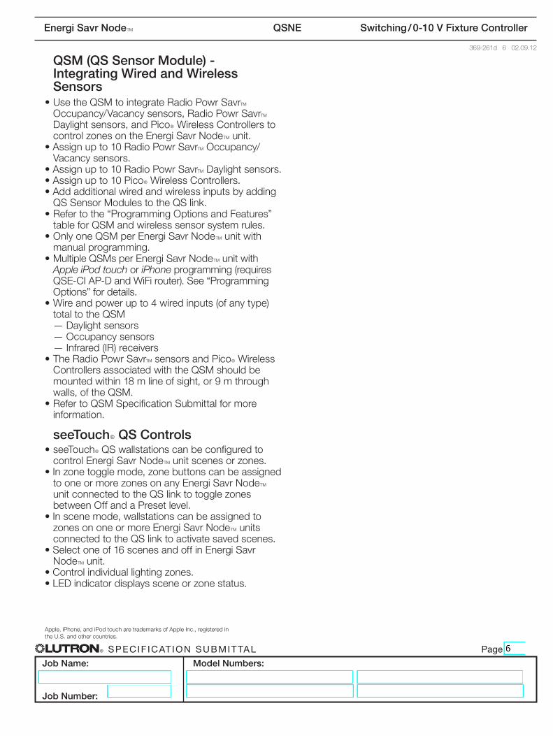
QSM (QS Sensor Module) - Integrating Wired and Wireless Sensors
•UsetheQSMtointegrateRadioPowrSavrT Occupancy/Vacancysensors,RadioPowrSavrT Daylightsensors,andPicoR Wireless Controllers to control zones on the Energi Savr NodeT unit.
•Assignupto10RadioPowrSavrT Occupancy/Vacancy sensors.
•Assignupto10RadioPowrSavrT Daylight sensors.•Assignupto10PicoR Wireless Controllers.•AddadditionalwiredandwirelessinputsbyaddingQSSensorModulestotheQSlink.
•Refertothe“ProgrammingOptionsandFeatures” table for QSM and wireless sensor system rules.
•OnlyoneQSMperEnergiSavrNodeT unit with manual programming.
•MultipleQSMsperEnergiSavrNodeT unit with Apple iPod touch or iPhoneprogramming(requiresQSE-CIAP-DandWiFirouter).See“ProgrammingOptions” for details.
• Wire and power up to 4 wired inputs (of any type) total to the QSM — Daylight sensors — Occupancy sensors —Infrared(IR)receivers
•TheRadioPowrSavrT sensors and PicoR Wireless Controllers associated with the QSM should be mountedwithin18mlineofsight,or9mthroughwalls,oftheQSM.
•RefertoQSMSpecificationSubmittalformoreinformation.
seeTouchR QS Controls•seeTouchRQSwallstationscanbeconfiguredto
control Energi Savr NodeT unit scenes or zones.•Inzonetogglemode,zonebuttonscanbeassigned
to one or more zones on any Energi Savr NodeT unitconnectedtotheQSlinktotogglezonesbetween Off and a Preset level.
•Inscenemode,wallstationscanbeassignedtozones on one or more Energi Savr NodeT units connectedtotheQSlinktoactivatesavedscenes.
•Selectoneof16scenesandoffinEnergiSavrNodeT unit.
•Controlindividuallightingzones.•LEDindicatordisplayssceneorzonestatus.
Apple,iPhone,andiPodtoucharetrademarksofAppleInc.,registeredinthe U.S. and other countries.
® Specif icat ion Submittal page
Job Name:
Job Number:
Model Numbers:
Energi Savr NodeT QSNE Switching / 0-10 V Fixture Controller
369-261d 7 02.09.12
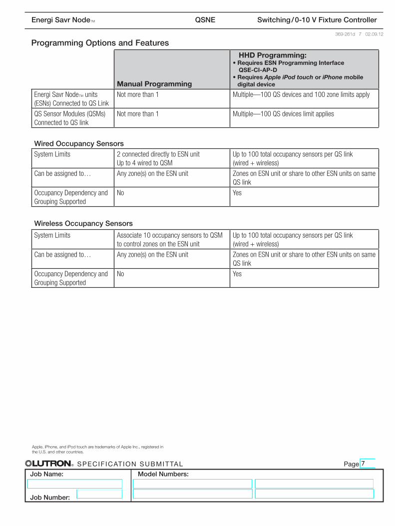
Programming Options and Features
Manual Programming
HHD Programming:• Requires ESN Programming Interface
QSE-CI-AP-D• Requires Apple iPod touch or iPhone mobile
digital device
Energi Savr NodeT units (ESNs) Connected to QS Link
Not more than 1 Multiple—100 QS devices and 100 zone limits apply
QS Sensor Modules (QSMs) Connected to QS link
Not more than 1 Multiple—100 QS devices limit applies
Wired Occupancy SensorsSystem Limits 2 connected directly to ESN unit
Up to 4 wired to QSMUp to 100 total occupancy sensors per QS link (wired + wireless)
Can be assigned to… Any zone(s) on the ESN unit Zones on ESN unit or share to other ESN units on same QS link
Occupancy Dependency and Grouping Supported
No Yes
Wireless Occupancy Sensors
System Limits Associate 10 occupancy sensors to QSM to control zones on the ESN unit
Up to 100 total occupancy sensors per QS link (wired + wireless)
Can be assigned to… Any zone(s) on the ESN unit Zones on ESN unit or share to other ESN units on same QS link
Occupancy Dependency and Grouping Supported
No Yes
Apple,iPhone,andiPodtoucharetrademarksofAppleInc.,registeredinthe U.S. and other countries.
® Specif icat ion Submittal page
Job Name:
Job Number:
Model Numbers:
Energi Savr NodeT QSNE Switching / 0-10 V Fixture Controller
369-261d 8 02.09.12
Programming Options and Features (continued)
Manual Programming
HHD Programming:• Requires ESN Programming Interface
QSE-CI-AP-D• Requires Apple iPod touch or iPhone mobile
digital device
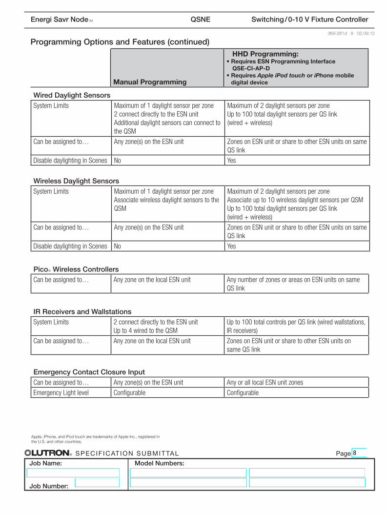
Wired Daylight SensorsSystem Limits Maximum of 1 daylight sensor per zone
2 connect directly to the ESN unit Additional daylight sensors can connect to the QSM
Maximum of 2 daylight sensors per zone Up to 100 total daylight sensors per QS link (wired + wireless)
Can be assigned to… Any zone(s) on the ESN unit Zones on ESN unit or share to other ESN units on same QS link
Disable daylighting in Scenes No Yes
Wireless Daylight SensorsSystem Limits Maximum of 1 daylight sensor per zone
Associate wireless daylight sensors to the QSM
Maximum of 2 daylight sensors per zone Associate up to 10 wireless daylight sensors per QSM Up to 100 total daylight sensors per QS link (wired + wireless)
Can be assigned to… Any zone(s) on the ESN unit Zones on ESN unit or share to other ESN units on same QS link
Disable daylighting in Scenes No Yes
PicoR Wireless ControllersCan be assigned to… Any zone on the local ESN unit Any number of zones or areas on ESN units on same
QS link
IR Receivers and WallstationsSystem Limits 2 connect directly to the ESN unit
Up to 4 wired to the QSMUp to 100 total controls per QS link (wired wallstations, IR receivers)
Can be assigned to… Any zone on the local ESN unit Zones on ESN unit or share to other ESN units on same QS link
Emergency Contact Closure InputCan be assigned to… Any zone(s) on the ESN unit Any or all local ESN unit zones
Emergency Light level Configurable Configurable
Apple,iPhone,andiPodtoucharetrademarksofAppleInc.,registeredinthe U.S. and other countries.
® Specif icat ion Submittal page
Job Name:
Job Number:
Model Numbers:
Energi Savr NodeT QSNE Switching / 0-10 V Fixture Controller
369-261d 9 02.09.12
Programming Options and Features (continued)
Manual Programming
HHD Programming:• Requires ESN Programming Interface
QSE-CI-AP-D• Requires Apple iPod touch or iPhone mobile
digital device
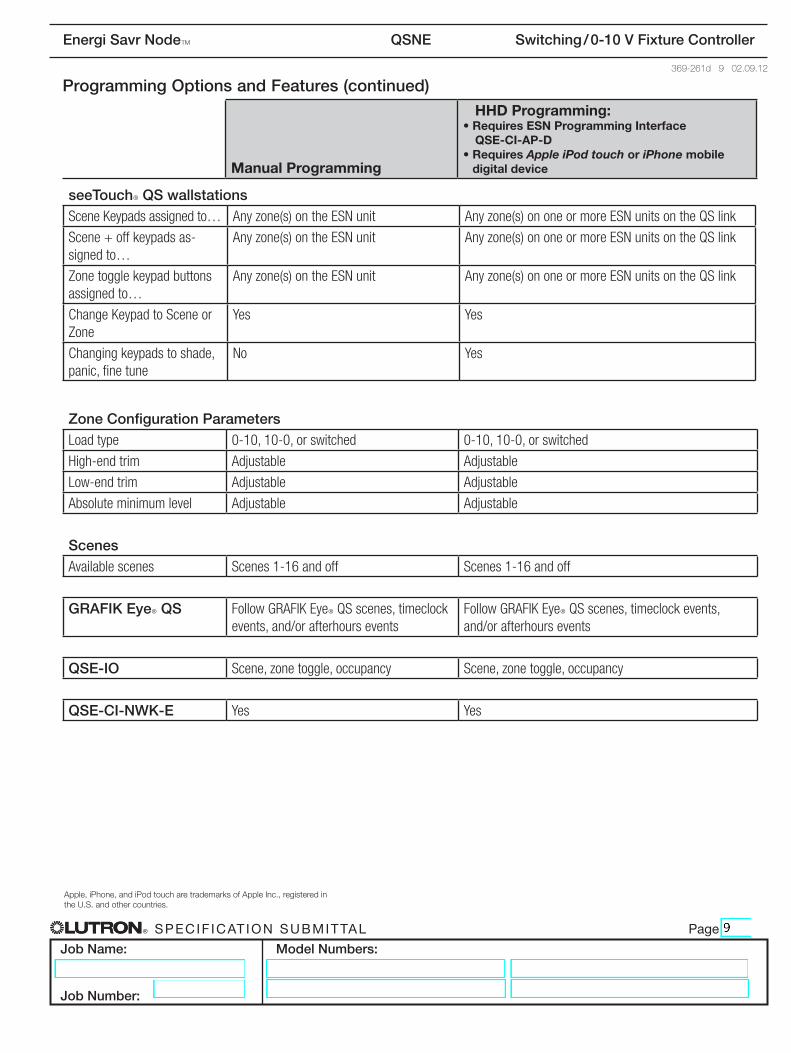
seeTouchR QS wallstationsScene Keypads assigned to… Any zone(s) on the ESN unit Any zone(s) on one or more ESN units on the QS link
Scene + off keypads as-signed to…
Any zone(s) on the ESN unit Any zone(s) on one or more ESN units on the QS link
Zone toggle keypad buttons assigned to…
Any zone(s) on the ESN unit Any zone(s) on one or more ESN units on the QS link
Change Keypad to Scene or Zone
Yes Yes
Changing keypads to shade, panic, fine tune
No Yes
Zone Configuration ParametersLoad type 0-10, 10-0, or switched 0-10, 10-0, or switched
High-end trim Adjustable Adjustable
Low-end trim Adjustable Adjustable
Absolute minimum level Adjustable Adjustable
ScenesAvailable scenes Scenes 1-16 and off Scenes 1-16 and off
GRAFIK EyeR QS Follow GRAFIK EyeR QS scenes, timeclock events, and/or afterhours events
Follow GRAFIK EyeR QS scenes, timeclock events, and/or afterhours events
QSE-IO Scene, zone toggle, occupancy Scene, zone toggle, occupancy
QSE-CI-NWK-E Yes Yes
Apple,iPhone,andiPodtoucharetrademarksofAppleInc.,registeredinthe U.S. and other countries.
® Specif icat ion Submittal page
Job Name:
Job Number:
Model Numbers:
Energi Savr NodeT QSNE Switching / 0-10 V Fixture Controller
369-261d 10 02.09.12
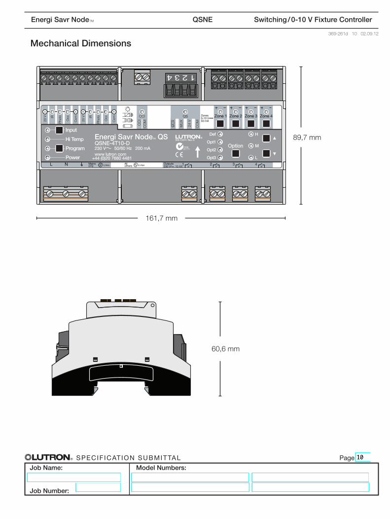
Mechanical Dimensions
N1771Z096
89,7mm
161,7mm
60,6mm
® Specif icat ion Submittal page
Job Name:
Job Number:
Model Numbers:
Energi Savr NodeT QSNE Switching / 0-10 V Fixture Controller
369-261d 11 02.09.12
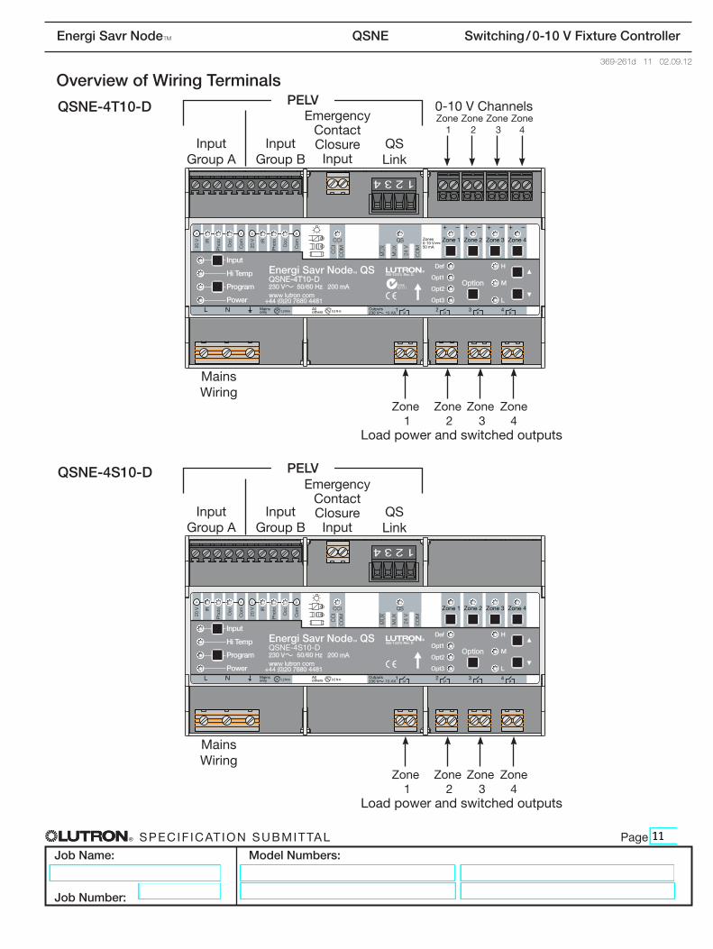
Overview of Wiring Terminals
N1771Z096
Mains Wiring
Mains Wiring
QS Link
QS Link
Input
Group A
Input
Group A
Input
Group B
Input
Group B
Zone 1
Zone 1
Zone 1
Zone 2
Zone 2
Zone 2
Zone 3
Zone 3
Zone 3
Zone 4
Zone 4
Zone 4
0-10 V ChannelsQSNE-4T10-D
QSNE-4S10-D
Load power and switched outputs
Load power and switched outputs
PELV
PELV
Emergency Contact Closure
Input
Emergency Contact Closure
Input
® Specif icat ion Submittal page
Job Name:
Job Number:
Model Numbers:
Energi Savr NodeT QSNE Switching / 0-10 V Fixture Controller
369-261d 12 02.09.12
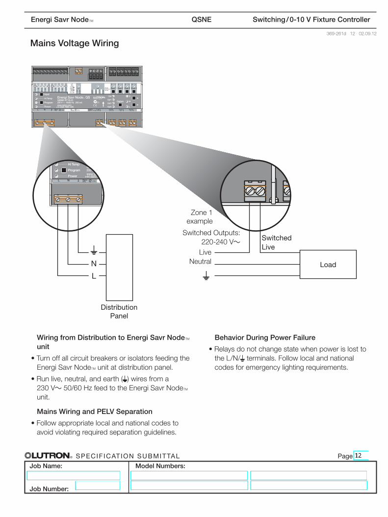
Mains Voltage Wiring
Wiring from Distribution to Energi Savr NodeT unit
•TurnoffallcircuitbreakersorisolatorsfeedingtheEnergi Savr NodeT unit at distribution panel.
•Runlive,neutral,andearth( ) wires from a 230V~50/60HzfeedtotheEnergi Savr NodeT unit.
Mains Wiring and PELV Separation
•Followappropriatelocalandnationalcodestoavoidviolatingrequiredseparationguidelines.
Behavior During Power Failure
•Relaysdonotchangestatewhenpowerislosttothe L/N/ terminals.Followlocalandnationalcodesforemergencylightingrequirements.
N1771Z096
Distribution Panel
N1771Z096
N1771Z096
N
L
LiveNeutral
Switched Live
Zone 1 example
Switched Outputs: 220-240 V~
Load
® Specif icat ion Submittal page
Job Name:
Job Number:
Model Numbers:
Energi Savr NodeT QSNE Switching / 0-10 V Fixture Controller
369-261d 13 02.09.12
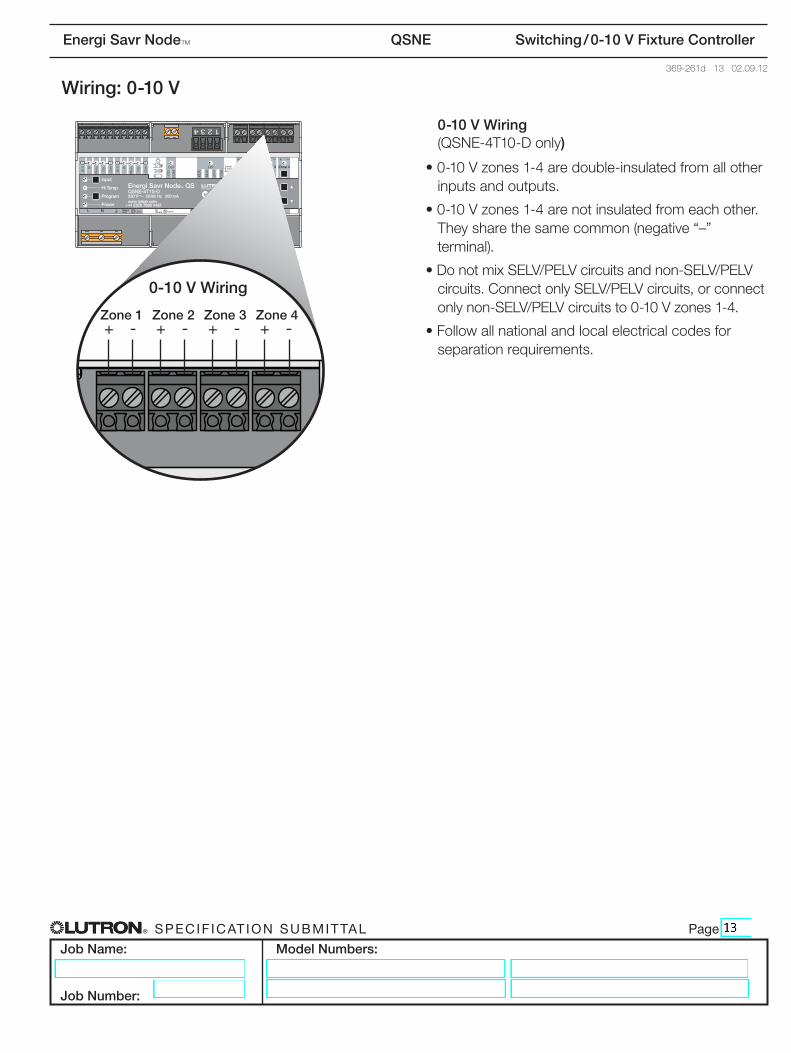
Wiring: 0-10 V
0-10 V Wiring (QSNE-4T10-D only)
•0-10 Vzones1-4aredouble-insulatedfromallotherinputs and outputs.
•0-10 Vzones1-4arenotinsulatedfromeachother.They share the same common (negative “–” terminal).
•DonotmixSELV/PELVcircuitsandnon-SELV/PELVcircuits.ConnectonlySELV/PELVcircuits,orconnectonlynon-SELV/PELVcircuitsto0-10 Vzones1-4.
•Followallnationalandlocalelectricalcodesforseparationrequirements.
N1771Z096
N1771Z096
Zone 1 Zone 2 Zone 3 Zone 4+ - + - + - + -
0-10 V Wiring
® Specif icat ion Submittal page
Job Name:
Job Number:
Model Numbers:
Energi Savr NodeT QSNE Switching / 0-10 V Fixture Controller
369-261d 14 02.09.12
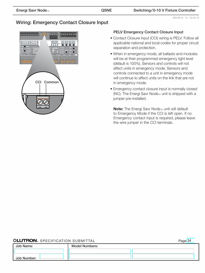
Wiring: Emergency Contact Closure Input
PELV Emergency Contact Closure Input
•ContactClosureInput(CCI)wiringisPELV.Followallapplicable national and local codes for proper circuit separation and protection.
•Wheninemergencymode,allballastsandmoduleswill be at their programmed emergency light level (default is 100%). Sensors and controls will not affect units in emergency mode. Sensors and controls connected to a unit in emergency mode willcontinuetoaffectunitsonthelinkthatarenot in emergency mode.
•Emergencycontactclosureinputisnormallyclosed(NC). The Energi Savr NodeT unit is shipped with a jumperpre-installed.
Note: The Energi Savr NodeT unit will default toEmergencyModeiftheCCIisleftopen.IfnoEmergencycontactinputisrequired,pleaseleavethewirejumperintheCCIterminals.
N1771Z096
N1771Z096
CCI Common
® Specif icat ion Submittal page
Job Name:
Job Number:
Model Numbers:
Energi Savr NodeT QSNE Switching / 0-10 V Fixture Controller
369-261d 15 02.09.12
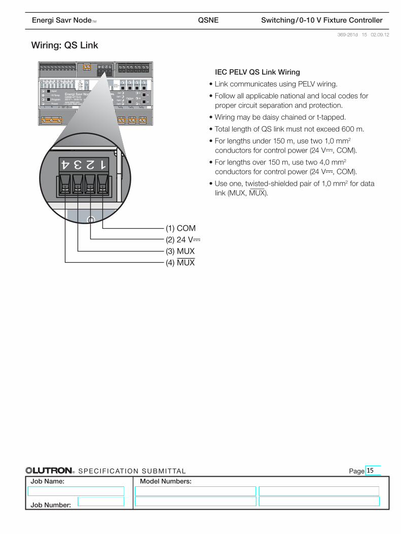
Wiring: QS Link
IEC PELV QS Link Wiring
•LinkcommunicatesusingPELVwiring.
•Followallapplicablenationalandlocalcodesforproper circuit separation and protection.
•Wiringmaybedaisychainedort-tapped.
•TotallengthofQSlinkmustnotexceed600m.
•Forlengthsunder150m,usetwo1,0mm2 conductors for control power (24 V-,COM).
•Forlengthsover150m,usetwo4,0mm2 conductors for control power (24 V-,COM).
•Useone,twisted-shieldedpairof1,0mm2 for data link(MUX,MUX).
N1771Z096
N1771Z096
(1) COM(2) 24 V-
(3) MUX(4) MUX
® Specif icat ion Submittal page
Job Name:
Job Number:
Model Numbers:
Energi Savr NodeT QSNE Switching / 0-10 V Fixture Controller
369-261d 16 02.09.12
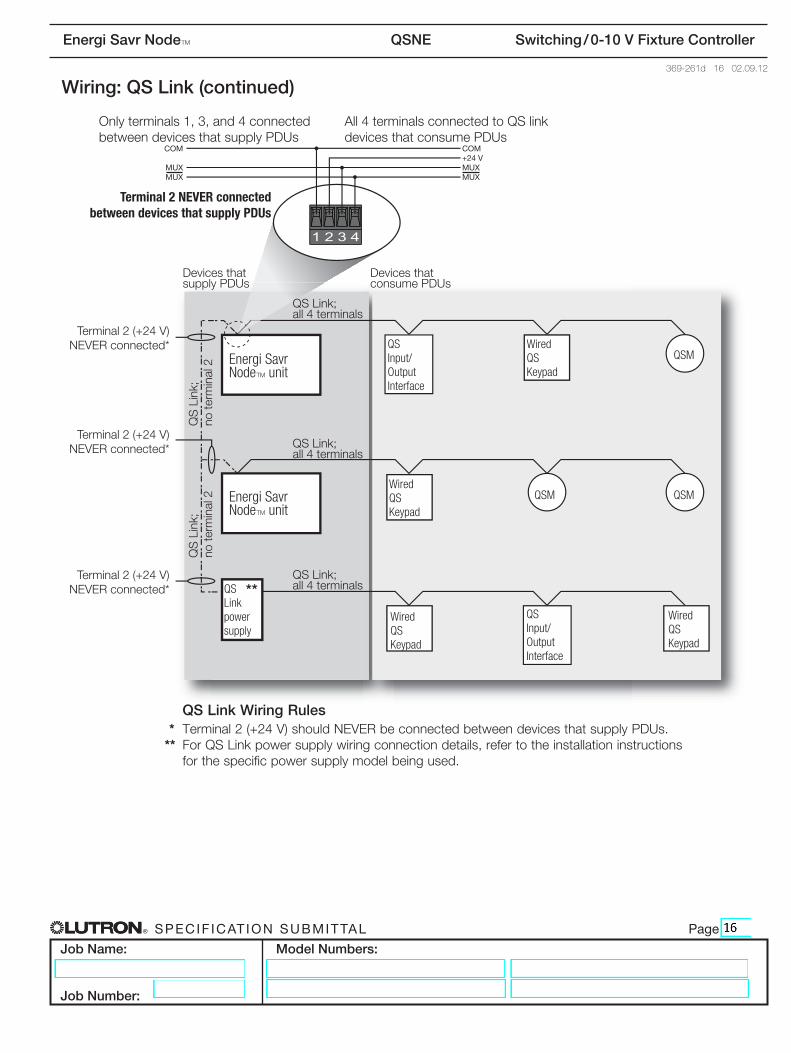
Wiring: QS Link (continued)
Onlyterminals1,3,and4connected between devices that supply PDUs
Terminal 2 NEVER connected between devices that supply PDUs
Terminal 2 (+24 V) NEVERconnected*
Devices that supply PDUs
Devices that consume PDUs
COM+24 VMUXMUX
COM
MUXMUX
Energi Savr NodeT unit
Energi Savr NodeT unit
QS Input/ Output Interface
Wired QS Keypad
QSM
QSMQSMWired QS Keypad
Wired QS Keypad
Wired QS Keypad
QS Input/ Output Interface
QS Link power supply
QSLink;all 4 terminals
QSLink;
no te
rmin
al 2
QSLink;
no te
rmin
al 2
QSLink;all 4 terminals
QSLink;all 4 terminals
Terminal 2 (+24 V) NEVERconnected*
Terminal 2 (+24 V) NEVERconnected* **
All4terminalsconnectedtoQSlink devices that consume PDUs
QS Link Wiring Rules * Terminal2(+24V)shouldNEVERbeconnectedbetweendevicesthatsupplyPDUs.** ForQSLinkpowersupplywiringconnectiondetails,refertotheinstallationinstructions
for the specific power supply model being used.
® Specif icat ion Submittal page
Job Name:
Job Number:
Model Numbers:
Energi Savr NodeT QSNE Switching / 0-10 V Fixture Controller
369-261d 17 02.09.12
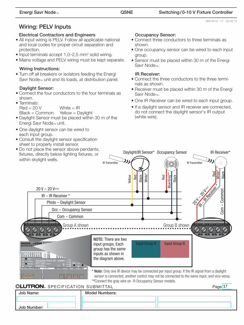
Wiring: PELV InputsElectrical Contractors and Engineers
•AllinputwiringisPELV.Followallapplicablenationaland local codes for proper circuit separation and protection.
•Inputterminalsaccept1,0–2,5mm2 solid wiring.•MainsvoltageandPELVwiringmustbekeptseparate.
Wiring Instructions:•TurnoffallbreakersorisolatorsfeedingtheEnergi
Savr NodeTunitanditsloads,atdistributionpanel.
Daylight Sensor:•Connectthefourconductorstothefourterminalsas
shown.•Terminals:Red=20V White=IRBlack=Common Yellow=Daylight
•DaylightSensormustbeplacedwithin30moftheEnergi Savr NodeT unit.
•Onedaylightsensorcanbewiredtoeach input group.
•Consultthedaylightsensorspecificationsheet to properly install sensor.
•Donotplacethesensorabovependants,fixtures,directlybelowlightingfixtures,orwithinskylightwells.
Occupancy Sensor:•Connectthreeconductorstothreeterminalsas
shown.•Oneoccupancysensorcanbewiredtoeachinput
group.•Sensormustbeplacedwithin30moftheEnergi
Savr NodeT.
IR Receiver:•Connectthethreeconductorstothethreetermi-
nals as shown.•Receivermustbeplacedwithin30moftheEnergi
Savr NodeT.•OneIRReceivercanbewiredtoeachinputgroup.•IfadaylightsensorandIRreceiverareconnected,donotconnectthedaylightsensor'sIRoutput(white wire).
* Note: Only one IR device may be connected per input group. If the IR signal from a daylight sensor is connected, another control may not be connected to the same input, and vice-versa.
** Connect the gray wire on -R Occupancy Sensor models.
IR Transmitter
20 V – 20 V-
IR – IR Receiver *
Photo – Daylight Sensor
Occ – Occupancy Sensor
Com – Common
20 V
– 20 V
-
IR – I
R Re
ceive
r *Co
m –
Com
mon
NOTE: There are two input groups. Each group has the same inputs as shown in the diagram above.
Input Group A Input Group B
Occupancy SensorDaylight/IR Sensor*
Red
Red
Blac
k
Blac
k
Blue
/Gra
y**
Yello
w Red
Blac
kW
hite
*
Whi
te*
IR Receiver*LUTRONR
LUTRONR
LUTRON
IR Transmitter
Group A shown Group B shown

® Specif icat ion Submittal page
Job Name:
Job Number:
Model Numbers:
Energi Savr NodeT QSNE Switching / 0-10 V Fixture Controller
369-261d 18 02.09.12
Programming Options
Detailsforeachoptioncanbefoundinthe“ProgrammingOptionsandFeatures”tableonthenextpage.
Manual Programming: •Use buttons on the front of the Energi Savr NodeT unit.•Use manual programming in installations with only one Energi Savr NodeT unit and with one QS Sensor Module(QSM)orfewerontheQSlink.
HHD Programming
•RequiresESNProgrammingInterface(QSE-CI-AP-D).•RequiresApple iPod touch or iPhone mobile digital device.•Use the intuitive programming application for the Apple iPod touch or iPhone to program systems with
multiple Energi Savr NodeTunitsandQSMsontheQSlink.
•WirelessrouteronlyrequiredforprogrammingwithanApple iPod touch or iPhone.•Wirelessroutermayberemovedfornormaloperation.•EthernetconnectionmaybemadeviaananEnergiSavrNodeTProgrammingInterface(QSE-CI-AP-D)oran
Energi Savr NodeTunitwithintegralEthernetjack.•LutronrecommendsthatanEnergi Savr NodeTProgrammingInterface(orEnergi Savr NodeT unit with Ether-netjack)bewiredtoanEthernetjackinthespaceforeaseofaccessandproximitytopowerforthewirelessrouter.
•Workswithanystandardwirelessrouterthatsupportsmulticastpackets.•Apple iPod touch or iPhone can program all Energi Savr NodeT units connected to an Energi Savr NodeT ProgrammingInterfaceviatheQSLink(exceptwhenpartofaQuantumR system).
•EnergiSavrappisrequiredandisavailablefromtheApple AppStoreonlinemarketplace.
Apple,iPhone,andiPodtoucharetrademarksofAppleInc.,registeredintheU.S.andothercountries.AppStoreisaservicemarkofAppleInc.
*Note:EnergiSavrNodeTunitsarenotdesignedtoexistonanopennetwork. Connectiontoanopennetworkcouldresultinreducedperformanceand Ethernet connectivity issues.
QSLink
Energi Savr NodeT unit
QSM
Dedicated Ethernet Connection for
Energi Savr NodeT units*
Apple iPod touch or iPhone
mobile digital deviceWireless
Router (by others)
Energi Savr NodeT Programming
InterfaceQSE-CI-AP-D
Wire types:1 Lessthan153m:Lutroncable
GRX-CBL-346S 153mto610m:Lutroncable GRX-CBL-46L
2 StandardCAT5/CAT5Ecable:Totallengthnottoexceed100m
1 1
22