Embed Size (px)
Citation preview

ENERGY 400Four Steps Chiller Heat Pump Controller
<IMG INFO>339,95195,850289,3514,15-1

1 CONTENTS
1 Contents .................................................................................................................................................................22 How to use this manual ......................................................................................................................................43 Introduction...........................................................................................................................................................5
3.1 Components .......................................................................................................................................................................................53.1.1 Basic Module ..................................................................................................................................................................................................................................53.1.2 Expansion ........................................................................................................................................................................................................................................53.1.3 Keyboards ........................................................................................................................................................................................................................................53.1.4 CF (Control Fan) Modules ...........................................................................................................................................................................................................53.1.5 Copy Card........................................................................................................................................................................................................................................53.1.6 Serial Interface (EWTK) ................................................................................................................................................................................................................53.1.7 Param Manager.............................................................................................................................................................................................................................5
4 Installation.............................................................................................................................................................64.1 Connection diagrams.......................................................................................................................................................................64.2 Dimensions .........................................................................................................................................................................................94.3 Configuration of analogue inputs.................................................................................................................................................94.4 Configuration of digital inputs ....................................................................................................................................................114.5 Configuration of outputs...............................................................................................................................................................12
4.5.1 Power outputs ..............................................................................................................................................................................................................................124.5.2 Low voltage outputs ...................................................................................................................................................................................................................124.5.3 Serial outputs ...............................................................................................................................................................................................................................12
4.6 Physical quantities and units of measurement ........................................................................................................................125 User Interface ..................................................................................................................................................... 13
5.1 Keys.....................................................................................................................................................................................................135.2 Display ...............................................................................................................................................................................................13
5.2.1 Display............................................................................................................................................................................................................................................135.2.2 Led ...................................................................................................................................................................................................................................................13
5.3 Wall-mounted keyboard ...............................................................................................................................................................145.4 Programming parameters – Menu levels ..................................................................................................................................145.5 Visibility of parameters and submenus ......................................................................................................................................16
5.5.1 Copy Card......................................................................................................................................................................................................................................16
6 System configuration........................................................................................................................................ 176.1 Compressors .....................................................................................................................................................................................176.2 Compressor configuration ............................................................................................................................................................17
6.2.1 Compressor (or power step) on/off sequences.....................................................................................................................................................................186.2.2 Compressor timing......................................................................................................................................................................................................................19
6.3 Condensation fan............................................................................................................................................................................206.3.1 Fan configuration........................................................................................................................................................................................................................206.3.2 Fan control configuration .........................................................................................................................................................................................................21
6.4 Reversing valves...............................................................................................................................................................................216.5 Hydraulic pump...............................................................................................................................................................................216.6 Anti-freeze/supplementary electrical heaters ..........................................................................................................................216.7 Internal fan.......................................................................................................................................................................................226.8 Condensation-Defrost probes ......................................................................................................................................................22
7 Temperature control functions ...................................................................................................................... 237.1 Setting set points.............................................................................................................................................................................237.2 Dynamic Set point ..........................................................................................................................................................................237.3 Load control .....................................................................................................................................................................................25
7.3.1 Compressor control – regulation algorithm ........................................................................................................................................................................257.3.2 Condensation fan control .........................................................................................................................................................................................................267.3.3 Combined or Separate Condensation ....................................................................................................................................................................................287.3.4 Hydraulic pump control ............................................................................................................................................................................................................287.3.5 Anti-freeze/supplementary electrical heater control .........................................................................................................................................................297.3.6 Reversing valve control ..............................................................................................................................................................................................................297.3.7.......................................................................................................................................................................................................................................................................29
8 Functions ............................................................................................................................................................. 308.1 Recording hours of operation ......................................................................................................................................................308.2 Defrost ...............................................................................................................................................................................................30

ENERGY 4003/58
8.2.1 Defrost start ..................................................................................................................................................................................................................................308.2.2 Control during defrost................................................................................................................................................................................................................318.2.3 Defrost end....................................................................................................................................................................................................................................31
9 Parameters.......................................................................................................................................................... 339.1 Description of Parameters.............................................................................................................................................................339.2 Parameters table .............................................................................................................................................................................38
10 Diagnostics ......................................................................................................................................................... 4210.1 List of alarms....................................................................................................................................................................................42
11 Technical features ............................................................................................................................................. 4911.1 Technical data .................................................................................................................................................................................4911.2 Electromechanical features ..........................................................................................................................................................4911.3 Regulations.......................................................................................................................................................................................49
12 Use of the device ................................................................................................................................................ 5012.1 Permitted use ...................................................................................................................................................................................5012.2 Forbidden use...................................................................................................................................................................................50
13 Responsibility and residual risks..................................................................................................................... 5114 Glossary ............................................................................................................................................................... 52

ENERGY 4004/58
2 HOW TO USE THIS MANUALx
This manual is designed to permit quick, easy reference with the following features:
References column:A column to the left of the text contains references to subjects discussed in the text to help you locate the information youneed quickly and easily.
Cross references:All words written in italics are referenced in the subject index to help you find the page containing details on this subject;supposing you read the following text:”when the alarm is triggered, the compressors will be shut down”The italics mean that you will find a reference to the page on the topic of compressors listed under the item compressorsin the index.If you are consulting the manual “on-line” (using a computer), words which appear in italics are hyperlinks: just click on aword in italics with the mouse to go directly to the part of the manual that discusses this topic.
Some segments of text are marked by icons appearing in the references column with the meanings specified below:
Take note: information on the topic under discussion which the user ought to keep in mind
Tip: a recommendation which may help the user to understand and make use of the information supplied onthe topic under discussion.
Warning! : information which is essential for preventing negative consequences for the system or a hazard topersonnel, instruments, data, etc., and which users MUST read with care.
References
Cross references
Icons for emphasis
IMG INFO
ENERGY 4005/58
3 INTRODUCTIONx
Energy 400 is a compact device that permits control of air conditioning units and heat pump of the following types:• air-air• air-water• water-water• water-air• motor-condensing
The controller can manage machines with up to four power steps distributed in a maximum of 2 cooling circuits (forexample, 2 circuits, with 2 compressors per circuit).Main characteristics:• Outflowing water temperature control• Condensation control• 2 inputs which may be configured for NTC or 4-20mA (through parameters)• 11 configurable digital inputs + (4 four optional)• Dynamic set point• Setting of parameters from the keyboard, with a personal computer or with a memory card• Remote keyboard (100 m) which may be connected up directly without serial interfaces.• 3 4-20 mA outputs• Control of 1, 2, 3, or 4 compressors.
3.1 Components
We will now look at the basic components and accessories in the system and how they are connected.
3.1.1 Basic ModuleThe basic module is an electronic card for connection with I/O resources and a CPU as described in the section onconnection diagrams.
3.1.2 ExpansionThe expansion module is an electronic card for connection as described in the section on connection diagrams.
3.1.3 KeyboardsTwo types of keyboard are available:• TS-P: Panel keyboard (32x74)• TS-W: Wall-mounted keyboard
3.1.4 CF (Control Fan) ModulesUsed to connect fans with Energy 400 low voltage outputs.
3.1.5 Copy CardCan be used to upload and download the Energy 400 parameter map.
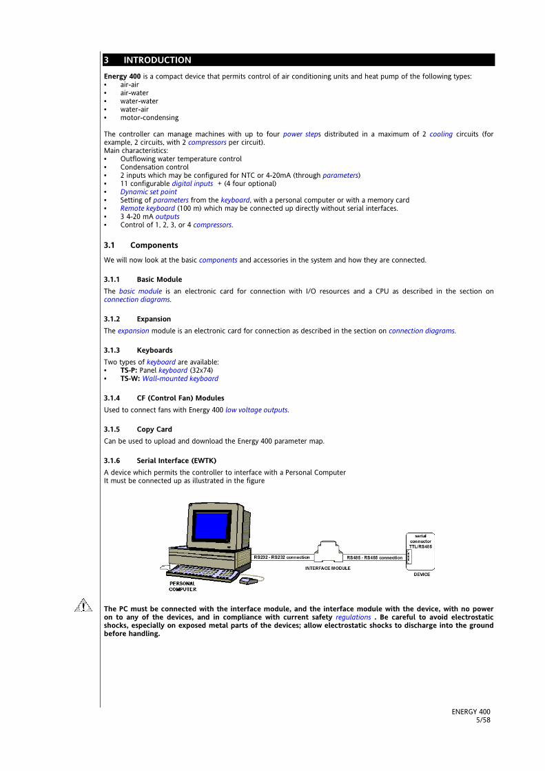
3.1.6 Serial Interface (EWTK)A device which permits the controller to interface with a Personal ComputerIt must be connected up as illustrated in the figure
The PC must be connected with the interface module, and the interface module with the device, with no poweron to any of the devices, and in compliance with current safety regulations . Be careful to avoid electrostaticshocks, especially on exposed metal parts of the devices; allow electrostatic shocks to discharge into the groundbefore handling.

ENERGY 4006/58
3.1.7 Param ManagerIf you have an adequate Personal Computer with Windows 95 or a more recent operating system, the Param Managersoftware, an adequate interface module and proper wiring, you can have full control over all Energy 400 parameters viaPersonal Computer.The instrument can be programmed easily and quickly using a series of interfaces which permit a logical, guided approach.

ENERGY 4007/58
<IMG INFO>42,4534,0512
4 INSTALLATIONx
Warning! Never work on electrical connections when the machine is switched on.Only qualified personnel should work on the equipmentBefore proceeding with any operation, first make sure that you have connected up the power supply to thedevice through an appropriate external current trransformer.Always follow these rules when connecting boards to one another and to the application:Never apply loads which exceed the limits set forth in these specifications to outputs;Always comply with connection diagrams when connecting up loads;To prevent electrical couplings, always wire low voltage loads separately from high voltage loads;
4.1 Connection diagrams
Basic module
Detail of connectors
Basic Module
Connections withNTC sensors
ALAR
M R
ELAY
RELA
Y CO
MM
ON
RELA
Y 1
RELA
Y 2
RELA
Y 3
RELA
Y 4
RELA
Y 5
RELA
Y 6
RELA
Y 7
CONN A CONN B
EXPA
NSI
ON
KBD
SERI
AL
- S +
12 AC ST1
ID1
GNDAN1 GND ST4 ST3 ST2
ID212AC 12DC TK1 ID5 ID4 ID3
NC ST5
ID6
GNDAN2 GND NC ID11 ST6
ID7NC 12DC TK2 ID10 ID9 ID8
CFCONTROL
CFCONTROL
Line
EMIFILTER

ENERGY 4008/58
Expansion Connectors
Connections withpressure sensor
ExpansionConnectors
diagram
12 AC ST1
ID1
GNDAN1 GND ST4 ST3 ST2
ID212AC 12DC TK1 ID5 ID4 ID3
CFCONTROL
Line
CONN A
NC ST5
ID6
GNDAN2 GND NC ID11 ST6
ID7NC 12DC TK2 ID10 ID9 ID8
CFCONTROL
CONN B
EMIFILTER
REL
AY
9
REL
AY
10
EXPA
NSI
ON
CONN C
CONN C
ID 1
5
ID 1
4
ID 1
3
ID 1
2
Com
mon
ENERGY 4009/58
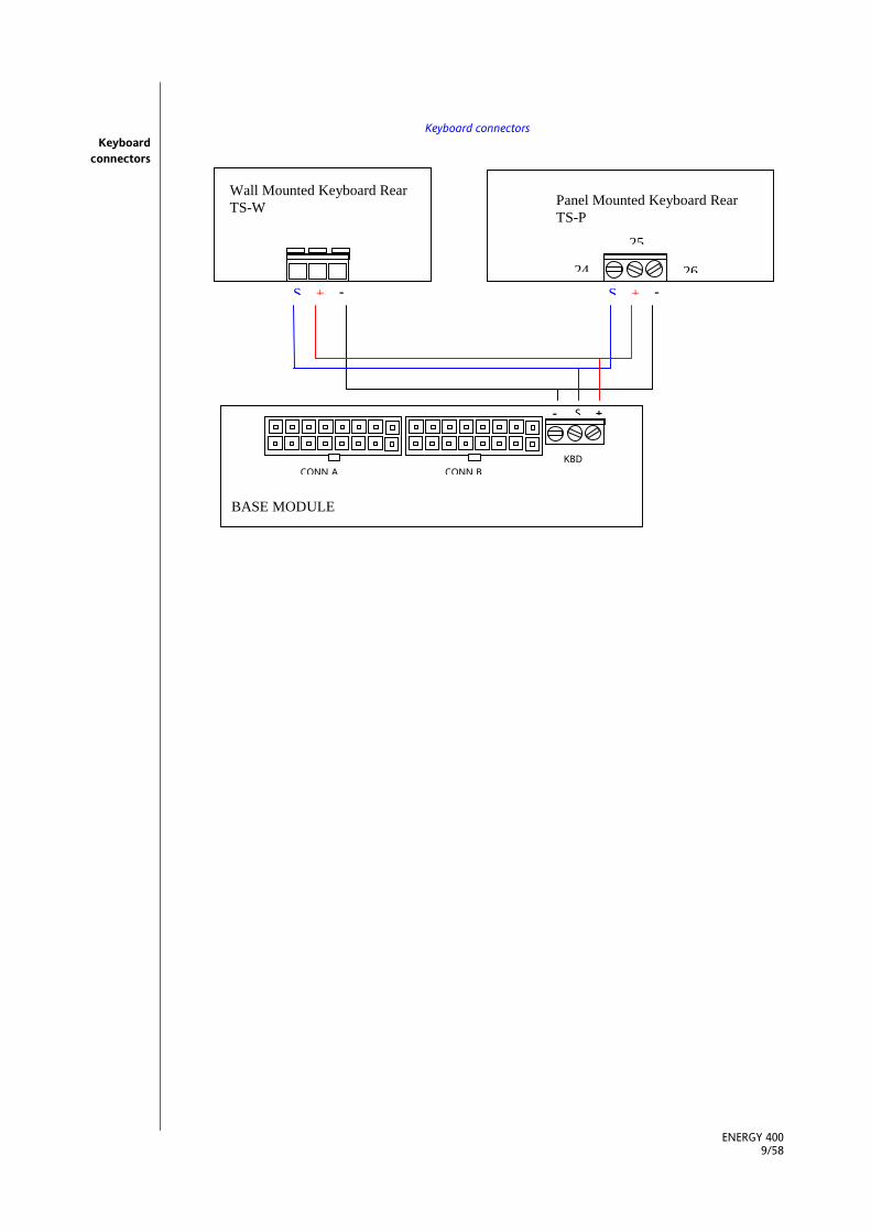
Keyboard connectorsKeyboard
connectors
Panel Mounted Keyboard RearTS-P
S + -24
25
26
Wall Mounted Keyboard RearTS-W
S + -
BASE MODULE
CONN A CONN BKBD
- S +

ENERGY 40010/58
4.2 Dimensions
4.3 Configuration of analogue inputs
There are 6 analogue inputs:• 4 NTC transducers,• 2 configurable NTC/4-20mA transducers.The following devices shall henceforth be referred to by the codes ST1….ST6:ST1 – Temperature control probe: inflowing water or air, reading range : -30°C ÷ 90°C;ST2 – Configurable probe, reading range: -30°C ÷ 90°C;ST3 - Configurable NTC probe, 4-20mAST4 - Configurable probe, reading range : -30°C ÷ 90°C;ST5 - Configurable NTC probe, 4-20mAST6 - Configurable probe, reading range: -30°C ÷ 90°C;
Basic ModuleDimension
Expansion moduledimension
Analogue inputs

ENERGY 40011/58
4 analogue inputs are available on the extension.The resolution of NTC analogue inputs is one tenth of a Kelvin degree;They are precise to within 0.8°C within the range of 0÷35°C and to within 0.8°C ÷ 3°C in the remainder of the scale.The 4-20mA input is precise to within 1% FS, with a resolution of one tenth of a Kelvin degree, if the input is configured asa dynamic set point, or Kpa*10 if the input is configured as a pressure probe.
ST1-ST6 probes can be configured according to the following table:
Value Pa. Description 0 1 2 3 4 5
H11 Configuration ofanalogue inputST1
Probeabsent
NTC input inflowingwater or air
Digital inputrequest forheating
Digital inputrequest fortemperaturecontrol
DifferentialNTC input
Not permitted
H12 Configuration ofanalogue inputST2
Probeabsent
NTC inputoutflowingwater/air,anti-freeze
Digital inputrequest forcooling
Not permitted Not permitted Not permitted
H13 Configuration ofanalogue inputST3
Probeabsent
NTC inputcondensation
4...20 mAcondensationinput
4...20 mAinput fordynamic setpoint
NTCantifreeze forwater-watergas reversalmachines
NTC heatingcontrol forwater-waterwater reversalmachines
H14 Configuration ofanalogue inputST4
Probeabsent
NTC inputcondensation
Multifunctional digital input
NTC input foroutdoortemperature
Not permitted Not permitted
H15 Configuration ofanalogue inputST5
Probeabsent
NTC inputoutflowingwater/air
Not permitted Not permitted Not permitted Not permitted
H16 Configuration ofanalogue inputST6
Probeabsent
NTC inputcondensationcircuit 2
4-20mA inputcondensation
Not permitted Antifreezeinput forwater-watergas reversalmachines
Not permitted
If inputs ST3 and ST6 are defined as 4-20mA inputs under pressure, the scale bottom value of the pressure input is alsosignificant:Pa H17= Maximum input value; set the corresponding value to a current of 20 mA
Analogue inputs:resolution and
precision
Analogue inputs:configuration
table

ENERGY 40012/58
<IMG INFO>28,329,31
4.4 Configuration of digital inputs
There are 11 voltage-free digital inputs, which will henceforth be identified as ID1….ID11.ST1, ST2, and ST4 may be added to these if they are configured as digital inputs (through parameters Pa H11, Pa H12, PaH14). 4 more digital inputs are available on the expansion.
The polarity of digital inputs is determined by the parameters listed below:ID1, ID2, ID3, ID4 defined by parameter Pa H18,ID5, ID6, ID7, ID8 defined by parameter Pa H19ID9, ID10, ID11, ST4 (if configured as digital) defined by parameter Pa H20ID12,ID13,ID14,ID15 on extension defined by parameter Pa N01
ID1 ID2 ID3 ID4ID5 ID6 ID7 ID8ID9 ID10 ID11 ST4
Pa H18Pa H19Pa H20Pa H21 ID12 ID13 ID14 ID15
0 Closed Closed Closed Closed1 Open Closed Closed Closed2 Closed Open Closed Closed3 Open Open Closed Closed4 Closed Closed Open Closed5 Open Closed Open Closed6 Closed Open Open Closed7 Open Open Open Closed8 Closed Closed Closed Open9 Open Closed Closed Open10 Closed Open Closed Open11 Open Open Closed Open12 Closed Closed Open Open13 Open Closed Open Open14 Closed Open Open Open15 Open Open Open Open
Example: A value of “10” for parameter Pa H18 indicates that digital inputs ID1 and ID3 are active when their contacts areclosed and digital inputs ID2 and ID4 are active when their contacts are open:
Pa H18 ID1 ID2 ID3 ID410 Closed Open Closed Open
If ST1 is configured as digital, its polarity is defined by parameter Pa H21If ST2 is configured as digital, its polarity is defined by parameter Pa H22
Parameter Value Description0 Active if closed1 Active if open
All digital inputs are configurable and may be given the meanings listed below by setting parameters Pa H23 through PaH34 and Pa N02 through Pa N05
Parameter Value Description
0 Input disabled1 Flow switch2 Remote OFF3 Remote Heat/Cool4 Thermal switch compressor 15 Thermal switch compressor 26 Thermal switch compressor 37 Thermal switch compressor 48 Thermal switch fan circuit 19 Thermal switch fan circuit 210 High pressure circuit 111 High pressure circuit 212 Low pressure circuit 113 Low pressure circuit 214 High pressure compressor 115 High pressure compressor 216 High pressure compressor 317 High pressure compressor 418 End of defrost circuit 119 End of defrost circuit 220 2° power step request21 3° power step request
Digital inputs
Digital inputs:polarity
Digital inputs:Polarity table
Digital inputs:Configuration
Table

ENERGY 40013/58
22 4° power step request
In the case of multiple inputs configured with the same value, the function associated with the input will carry out aLogical OR among the inputs.
4.5 Configuration of outputs
There are two basic types of outputs: power outputs, and low voltage outputs.
4.5.1 Power outputsThere are 8 power outputs, which shall henceforth be referred to as RL1…RL8 (relays).RL1 - compressor 1, 5 A 125VAC/230VAC Res; ¼ HP 230VAC, 1/8 HP 125VAC;RL2 - configurable, 5 A 125VAC/230VAC Res; ¼ HP 230VAC, 1/8 HP 125VAC;RL3 - configurable, 5 A 125VAC/230VAC Res; ¼ HP 230VAC, 1/8 HP 125VAC;RL4 - configurable, 5 A 125VAC/230VAC Res; ¼ HP 230VAC, 1/8 HP 125VAC;RL5 - configurable, 5 A 125VAC/230VAC Res; ¼ HP 230VAC, 1/8 HP 125VAC;RL6 - configurable, 5 A 125VAC/230VAC Res; ¼ HP 230VAC, 1/8 HP 125VAC;RL7 - configurable, 5 A 125VAC/230VAC Res; ¼ HP 230VAC, 1/8 HP 125VAC;RL8 – cumulative alarm, 5 A 125VAC/230VAC Res; ¼ HP 230VAC, 1/8 HP 125VAC;There are 2 additional digital outputs in the extension module:RL9 - configurable, 5 A 125VAC/230VAC Res; ¼ HP 230VAC, 1/8 HP 125VAC;RL10 - configurable, 5 A 125VAC/230VAC Res; ¼ HP 230VAC, 1/8 HP 125VAC;
Configurable outputs may be given the following meanings by setting parameters Pa H35 through Pa H40 and Pa N06through Pa N07
Value Description0 Disabled1 Reversal valve circuit 12 Reversal valve circuit 23 Condenser fan circuit 14 Condenser fan circuit 25 Electrical heater 16 Electrical heater 27 Pump8 Evaporator fan9 Power Step 210 Power Step 311 Power Step 4
Polarity of RL2,RL3,RL4,RL5,RL8 may be selected using Pa H41-Pa H45
Parameter Value Description
0 Relay closed if output active1 Relay open if output not active
If multiple outputs are configured with the same resource, the outputs will be activated in parallel.
4.5.2 Low voltage outputsThere are a total of 4 low voltage outputs available: 2 phase cut outputs and 2 4-20 mA outputs:TK1 – Output for piloting external fan control modules in circuit 1.TK2 – Output for piloting external fan control modules in circuit 2.AN1 - 4-20mA output for control of fans in circuit 1AN2 - 4-20mA output for control of fans in circuit 2
Outputs AN1 and AN2, though their connections are physically separate, are alternatives to outputs TK1 and TK2 which areselected by parameters Pa H45 and Pa H46Fan config. parameter Index Value 0 Value 1
Fan 1 output H45 Fan 1 output in phase cut Fan 1 output in 4-20 mAFan 2 output H46 Fan 2 output in phase cut Fan 2 output in 4-20 mA
4.5.3 Serial outputsThere are 2 asynchronous serials on the control:• channel for serial communication with a personal computer through a Microtech interface module (966,e,8,1)• channel for serial communication with a standard Microtech keyboard. Power supply 12 VDC (2400,e,8,1).
4.6 Physical quantities and units of measurement
Parameter Pa H64 may be used to set temperature display in either degrees °C or degrees °F:
Outputs
Configurationtable
Polarity Table
Configuration offan outputs

ENERGY 40014/58
Pa H64 Unit ofmeasurement
0 Degrees °C1 Degrees °F
Unit ofmeasurement:
selection

ENERGY 40015/58
IMG INFO
<IMG INFO>
<IMG INFO>36,75
<IMG INFO>
5 USER INTERFACEx
The interface on the front panel of the instrument can be used to carry out all the operations connected to the use of theinstrument, and in particular to:• Set operating mode• Respond to alarm situations• Check the state of resources
Front panel of the instrument
The instrument can function without the aid of a keyboard
5.1 Keys
Selects operating mode:
If the heating mode is enabled, each time the key is pressed the following sequence occurs:Stand-by -!!!! cooling !!!! heating !!!! stand-by
if heating mode is not enabled:Stand-by !!!! cooling !!!! stand-by
In menu mode, this key acts as a SCROLL UP or UP key (increasing value).
Resets alarms, and turns the instrument on and off.
Press once to reset all manually reset alarms not currently active; all the alarm events per hour will also be reset even if thealarms are not active.Hold down the key for 2 seconds to turn the instrument from on to off or vice versa. When it is off, only the decimal pointremains on the display. In menu mode this key acts as a SCROLL DOWN or DOWN key (decreasing value).
Pressing the “mode” and “on-off” keys at the same time:
If you press both keys at the same time and then release within 2 seconds, you will move one level deeper in the displaymenu.If you press both keys for more than 2 seconds you will move one level up.If you are currently viewing the lowest level in the menu and you press both keys and release within 2 seconds, you will goup one level.
5.2 Display
The device can communicate information of all kinds on its status, configuration, and alarms through a display and anumber of leds on its front panel.
5.2.1 DisplayNormal display shows:• regulation temperature in tenths of degrees celsius or fahrenheit• the alarm code, if at least one alarm is active. If multiple alarms are active, the one with greater priority will be
displayed, according to the Table of Alarms.• If temperature control is not analogue and depends on the status of a digital input (ST1 or ST2 configured as digital
inputs), the “On” or “Off” label will be displayed, depending on whenther temperature control is active or not.• When in menu mode, the display depends on the current position; labels and codes are used to help the user identify
the current function.
5.2.2 LedLed 1 compressore 1.ON if compressor 1 is active• OFF if compressor 1 if off• Rapid BLINK if safety timing is in progress• Slow BLINK if compressor is currently set to defrost
Power step 2 ledON if power step 2 is active
Keyboard
Mode
On-off – Alarmsreset
Combination mode– onoff keys

ENERGY 40016/58
<IMG INFO>
• OFF if power step 2 is not active• Rapid BLINK if safety timing is in progress• Slow BLINK if step 2 is currently defrosting
Led step 3 di potenzaON se lo step 3 di potenza è attivo• OFF se lo step 3 di potenza non è attivo• BLINK veloce se sono in corso temporizzazioni di sicurezza• BLINK lento se step 3 in sbrinamento
Power step 4 led• ON if power step 4 is active• OFF if power step 4 is not active• Rapid BLINK if safety timing is in progress• Slow BLINK if step 4 is defrosting
Electrical heater/boiler led• ON if at least one internal anti-freeze electrical heater or boiler is enabled• OFF if both are off
Heating Led• ON if the device is in heating mode.
Cooling Led• ON if the controller is in cooling mode
If neither the HEATING led nor the COOLING led are in, the controller is in STAND-BY mode.When it is off, only the decimal point appears on the display.
5.3 Wall-mounted keyboard
The remote keyboard a on the display is an exact copy of the information displayed on the instrument, with the same leds;Remote keyboard
It performs exactly the same functions as those described in the display section.The only difference is in use of the UP and DOWN keys (to increase and decrease value), which are separate from theMODE and ON/OFF keys.
5.4 Programming parameters – Menu levels
Device parameters may be modified using a Personal Computer (with the required software, interface key and cables), orusing the keyboard;If using the keyboard, access to parameters is arranged in a hierarchy of levels which may be accessed by pressing the“mode and “on-off” keys at the same time (as described above).Each menu level is identified by a mnemonic code which appears on the display.The structure is set up as shown in the diagram below:
Remote keyboard

ENERGY 40017/58
Menu structure
Control probeCurrent alarm
Set point:
Analogue Inp.:
Alarms:
Digital input:
Op. hours:
Password:
Parameters:
Label cooling set:
Label heating set:
Input code.: -
Current alarms Code:
Input code: -
Value heating set
Value cooling set
Configuration par.:
Compressor par.:
Fan control par.:
Alarms par.:
Pump par.:
Antifreeze par.:
Defrost par.:
Par. index -
Parameter value
Number of hours par.
Parameter value
Parameter value
Parameter value
Parameter value
Parameter value
Parameter value
Comp. hours: -
Password value
Status of digital input
Val. analogue input
Par. index -
Par. index -
Par. index -
Par. index -
Par. index -
Par. index -
Pump hours: Number of hours par.
Expansion par.: Par. index. .. Parameter value

ENERGY 40018/58
5.5 Visibility of parameters and submenus
With a personal computer, interface key, suitable cables and the “Param Manager” software, it is possible to restrict thevisibility and modification of parameters and entire submenus.A “visibility value” may be assigned to each parameter, as described below:
Value Meaning0003 Parameter or label visible at all times0258 Parameter or label visible if user password entered correctly (password = Pa
H67)0770 Parameter or label visible if user password entered correctly (password = Pa
H67). Parameter cannot be modified.0768 Parameter visible from PC only.
Some visibility settings are factory set.For more information, please refer to the “Param Manager” instructions.
5.5.1 Copy Card
The copy card can store the whole map of Energy 400 parameters;To download the map present in the copy card, proceed as follows:1. Connect the key to the appropriate Energy 400 output (refer to connection diagrams) while the device is off.2. Turn on the Energy 400: the parameters map in the copy card will be copied to the Energy 400.
To store the Energy 400 parameters map in memory, proceed as follows:1. Connect the copy card to the appropriate Energy 400 output (refer to connection diagrams) while the device is on.2. From the keyboard, access the “password” submenu (refer to menu structure) and set the value contained in
parameter Pa H46: The instrument’s map will be downloaded to the copy card.3. Disconnect the copy card when finished.
label

ENERGY 40019/58
6 SYSTEM CONFIGURATIONx
In this section we will look at how to configure parameters for various loads on the basis of the type of installation to becontrolled.
6.1 Compressors
Energy 400 can control systems consisting of up to two cooling circuits with 1 to 4 compressors.If there is a capacity step, it will be considered as a compressor.Each compressor is piloted by a device relay (power outputs) (each capacity step requires an additional output).The first compressor must be connected to output RL1; the remaining outputs (RL2…RL7) (RL9…RL10 on extension) may beassigned at will, setting the value of the parameters Pa H35 …. PaH40 (Pa N06 … Pa N07 if there is no extension).The compressors will be turned on or off depending on the temperatures detected and the temperature control functionsthat have been set (refer to the section on Compressor controls – Regulation algorithml )
6.2 Compressor configuration
The turning on of an additional compressor (or capacity step) will henceforth be referred to as a Power step (power level).
It’s of main importance to identify the right compressor indexes to be assigned to the related diagnostic digitalinputs. In a 2 circuit with 1 compressor each machine, for example (see next table), compressors 1 and 3 areenabled. The compressor n° 3 stops if an alarm occurs on digital input 3: the related alarm code appears on thediusplay. If an alarm occurs on digital input 2, an alarm code appears on the display, but no compresssor will bestopped for that, since there is no compressor number 2.Partializations belonging to a compressor in alarm condition are shut down. The leds of working compressors refer topower step indexes
The following configurations are available for compressors without capacity steps (Pa H07=0):
Number of compressors per circuit1 (Pa H06=1) 2 (Pa H06=2)
1(Pa
H05=1)
RL1=comp. 1 circ.1 (alarm index 1) RL1=comp. 1 circ. 1 (alarm index 1)Step2 = comp 2 circ.1 (alarm index 2)
Num
ber
of c
ircu
its
2(Pa
H05=2)
RL1=Comp. 1 circ.1 (alarm index 1)Step3 = comp. 1 circ.2 (alarm index 3)
RL1=comp. 1 circ. 1 (alarm index 1)Step2 = comp 2 circ.1 (alarm index 2)Step3 = comp 1 circ.2 (alarm index 3)Step4 = comp 2 circ.2 (alarm index 4)
Number of compressors per circuit3 (Pa H06=1) 4 (Pa H06=2)
1(Pa
H05=1)
RL1=comp. 1 circ.1 (alarm index 1)Step2 = comp 2 circ.1 (alarm index 2)Step3 = comp. 3 circ.1 (alarm index 3)
RL1=comp. 1 circ. 1 (alarm index 1)Step2 = comp 2 circ.1 (alarm index 2)Step3 = comp 3 circ.1 (alarm index 3)Step4 = comp 2 circ.1 (alarm index 4)
Num
ber
of c
ircu
its
2(Pa
H05=2)
Configuration error Configuration error
The following configurations are available for compressors with 1 capacity step (Pa H07=1):
Number of compressors per circuit1 (Pa H06=1) 2 (Pa H06=2)
Num
ber
ofci
rcui
ts
1(Pa
H05=1)
RL1=comp. 1 circ. 1 (alarm index 1)Step2 = cap. step1 Comp.1 circ.1
RL1=comp. 1 circ. 1 (alarm index 1)Step2 = cap. step1 Comp.1 circ.1Step3 = comp.2 circ.1 (alarm index 2)Step4 = cap. step1 Comp.2 circ.1
Power step
Simplecompressors
with 1 capacitystep

ENERGY 40020/58
2(Pa
H05=2)
RL1=comp. 1 circ. 1 (alarm index 1)Step2 = cap. step1 comp.1 circ.1Step3 = comp.1 circ.2 (alarm index 3)Step4 = cap. step1 comp.1 circ.2
Configuration error
The following configurations are available for compressors with 2 or 3 capacity steps (Pa H07=2 or Pa H07=3):
Number of compressors per circuit1 (Pa H06=1 and Pa H07=2) 2 (Pa H06=2 and Pa H07=3)
1(Pa
H05=1)
RL1=comp. 1 circ. 1 (alarm index 1)Step2 = cap. step1 comp.1 circ.1Step4 = cap. step2 comp.1 circ.1
RL1=comp. 1 circ. 1 (alarm index 1)Step2 = cap. step1 comp.1 circ.1Step3 = cap. step2 comp.1 circ.1Step4 = cap. step3 comp.1 circ.1
Num
bero
of c
ircui
ts
2(pa
H05=2)
Configuration error Configuration error
6.2.1 Compressor (or power step) on/off sequencesDepending on the temperature conditions detected by the probes, the temperature control functions of the “Energy 400”may request turning on and off of compressors/capacity steps (power steps).The sequence in which compressors/capacity steps (steps) are turned on and off may be determined by adjusting thevalues of parameters Pa H08 and Pa H09 as described below:
Parameter valuePar Description 0 1
Pa H08 Power step on sequence Depends on number of hours ofoperation
Unvaried on sequence
Pa H09 Circuit balacing Circuit saturation Circuit balancing
When on sequences depend on the number of hours of operation, of 2 available compressors, the one which has beenoperated for less hours will come on first, and the one which has been operated for more hours will always go off first. Inan unvaried on sequence, the compressor with the lower number will always come on first (compressor 1 beforecompressor 2) and the compressor with the higher number will always go off first.
The circuit balancing parameter is significant only if there are 2 circuits and 2 steps per circuit. If we select H09=0, allpower steps in one circuit will come on before those in the other circuit. If H09=1 (balancing), power steps will come on insuch a way that both circuits are delivering the same power, or the difference is no more than one step.
Let us take a closer look at the various combinations:
Pa H08=0 Pa H09=0CASE OF 1 COMPRESSOR WITH CAPACITY STEP PER
CIRCUIT:CASE OF 2 COMPRESSORS PER CIRCUIT:
The compressor with the least hours of operation comes onfirst, then the capacity step for the same circuit, thecompressor on the other circuit, and, lastly, its capacity step.When turning off, the capacity step of the compressor withthe most hours of operation goes off first, then thecorresponding compressor, then the other capacity step andfinally the other compressor.
Example:Supposing the system has been configured as follows:RL1=Compressor 1 circuit 1Step2 = capacity step compressor 2Step3 = compressor 2 circuit 2Step4 = capacity step compressor 2Ifhours comp.1 > hours comp.2they will come on in this orderStep3!!!!Step4!!!!RL1!!!!Step2and go off in this orderStep2!!!!RL1!!!!Step4!!!!Step3
If all compressors are off to start with, the circuit which hasthe lower average number of hours for all its compressorswill come on first. In this circuit the compressor with theleast hours of operation will come on first, followed by theother compressor in the same circuit: thus the circuit issaturated. The next step is chosen between the twocompressors in the other circuit with fewer hours.
Example:Supposing the system has been configured as follows:RL1=Compressor 1 circuit 1Step2 = compressor 2 circuit 1Step3 = compressor 3 circuit 2Step4 = compressor 4 circuit 2Ifhours comp.1 > hours comp.2hours comp.4 > hours comp.3(hours comp.1 + hours comp.2)/2>(hours comp.4 +hours comp.3)/2 they will come on in this orderStep3!!!!Step4!!!!Step2!!!!RL1and go off in this order
with 2 or 3capacity steps
Compressors:coming on on thebasis of hours of
operation andcircuit saturation

ENERGY 40021/58
RL1!!!!Step2!!!!Step4!!!!Step3
Pa H08=0 and Pa H09=1CASE OF 1 COMPRESSOR WITH CAPACITY STEP PER
CIRCUIT:CASE OF 2 COMPRESSORS PER CIRCUIT
The compressor with the least hours of operation comes onfirst, followed by the compressor in the other circuit, thecapacity step of the first circuit to come on, and, lastly, theother capacity step. When going off, the capacity step of thecompressor with the most hours goes off first, followed bythe capacity step of the other compressor, the compressorwith the most hours and, lastly, the remaining compressor.
Example:Supposing the system has been configured as follows:RL1=Compressor 1 circuit 1Step2 = capacity step compressor 2Step3 = compressor 3 circuit 2Step4 = capacity step compressor 3ifhours comp.1 > hours comp.3they will come on in this orderStep3!!!!RL1!!!!Step4!!!!Step2and go off in this orderStep2!!!!Step4!!!!RL1!!!!Step3
If all compressors are off to start with, the circuit with thelower average number of hours for its compressors will comeon first. The average is calculated as the ratio between thetotal number of hours of the compressors available and thenumber of compressors in the circuit. In this circuit, thecompressor with the least hours will come on first, then thecompressor in the other circuit with the least hours, theother compressor in the first circuit and, lastly, theremaining compressor.
Example:Supposing the system has been configured as followsRL1=Compressor 1 circuit 1Step2 = compressor 2 circuit 1Step3 = compressor 3 circuit 2Step4 = compressor 4 circuit 2ifhours comp.1 > hours comp.2hours comp.4 > hours comp.3(hours comp.1 + hours comp.2)/2>(hours comp.4 +hours comp.3)/2 they will come on in this orderStep3!!!!Step2!!!!Step4!!!!RL1and go off in this orderRL1!!!!Step4!!!!Step2!!!!Step3
Pa H08=1 and Pa H09=0CASE OF 1 COMPRESSOR WITH CAPACITY STEP PER CIRCUIT CASE OF 2 COMPRESSORS PER CIRCUITThe compressor con with the lower number comes on first,then its capacity step, then the compressor in the othercircuit and, lastly, its capacity step. The capacity step for thecompressor with the highest number is the first to go off,followed by the capacity step of the other compressor, andfinally the compressor.
Example:Supposing the system has been configured as follows:RL1=Compressor 1 circuit 1Step2 = capacity step compressor 2Step3 = compressor 3 circuit 2Step4 = capacity step compressor 3they will come on in this orderRL1!!!!Step2!!!!Step3!!!!Step4and go off in this orderStep4!!!!Step3!!!!Step2!!!!RL1
Exactly the same as the first case.
Pa H08=1 e Pa H09=1CASE OF 1 COMPRESSOR WITH CAPACITY STEP PER CIRCUIT CASE OF 2 COMPRESSORS PER CIRCUITThe compressor with the lowest number comes on first,then the compressor in the other circuit, the capacity stepof the first compressor and then the capacity step of thesecond compressor. They go off in reverse order.
Example:Supposing the system has been configured as follows:RL1=Compressor 1 circuit 1Step2 = capacity step compressor 2Step3 = compressor 3 circuit 2Step4 = capacity step compressor 3they will come on in this orderRL1!!!!Step3!!!!Step2!!!!Step4and go off in this orderStep4!!!!Step2!!!!Step3!!!!RL1
Exactly the same as the first case.
In the unvaried sequence, if the compressor with the lower number is unavailable, the compressor with the higher numbercomes on.If the compressor comes available and the amount of power required is equal to the amount of power being delivered,the machine will continue to function in its current state: it will not turn off a compressor with a higher number to turn ona compressor with a lower number.
A compressor is unavailable when it is shut down due to an alarm or is currently counting safety timing.
Compressors:coming on on thebasis of hours of
operation andcircuit balancing
Compressors:unvaried on
sequence withcircuit saturation
Compressors:unvaried on
sequence withcircuit balancing

ENERGY 40022/58
6.2.2 Compressor timingThe turning on and off of compressors must comply with safety times which may be set by the user using the parametersspecified below:
There is a safety interval between the time a compressor goes off and the time the same compressor comes back on(compressor on…off safety time, controlled by parameter Pa C01);This interval of time must elapse when the “Energy 400” is turned on.
There is a safety interval between the time a compressor is turned on and the time it is turned on again (compressoron...on safety time, controlled by parameter Pa C02) .
If the machine has multiple power steps, there are intervals of time which must pass between turning on of 2 compressors(Pa C06) and turning off of 2 compressors (Pa C07). An amount of time determined by parameter Pa C08 (capacity step ondelay) must elapse between the turning on of one compressor or capacity step and the turning on of any othercompressor or capacity step on the machine. The greatest of the currently active safety times must be applied to eachcompressor.The off time interval between compressors is not applied in the event of a compressor shutdown alarm, in which casethey stop immediately.
6.3 Condensation fan
“Energy 400” may be connected with two types of fan piloting unit:
• Triak• 4-20 mA
6.3.1 Fan configurationFirst of all, correctly configure the type of analogue output (low voltage outputs) to which the fan control module(s) areconnected;the relevant parameters are Pa H46 for the first circuit and Pa H47 for the second circuit, as shown in the table below:
Parameter value Circuit 1 – Pa H46 Circuit 2 – Pa H47
Safety timing
Off-on timing
On-on timing
Off-on and on-ondiagram for 1
compressor
On-on off-offtimes for 2 comp.
on-on and off-offdiagram 2 comp
Compressor
ON
OFF
OFF – ON safety timePa C01
Seconds*10
ON – ON safety timePa C02
Comp.1
ON
OFF
Interval betweenturning offcompressors Pa C07
Seconds
Interval between turning oncompressors Pa C05
Comp.2ON
OFF
Seconds

ENERGY 40023/58
<IMG INFO>36,75
<IMG INFO>36,6
0 TK output enabled for phasecut
TK output enabled for phasecut
1 Enable 4-20 mA output AN1 Enable 4-20 mA output AN2
If the output is configured as a proportional triac, the parameters PICK-UP, PHASE SHIFT, and IMPULSE DURATION are alsosignificant.
Every time the external fan is started up, power is supplied to the exchanger fan at maximum voltage, and the fan operatesat maximum speed, for an amount of time equal to Pa F02 seconds/10; after this time the fan operates at the speed set bythe regulator.Pa F02 = Fan pick-up time (seconds/10)
Determines a delay during which it is possible to compensate the different electrical characteristics of the fan drivemotors:Pa F03 = duration of fan phase shift expressed in microseconds*200 (1 unit = 200 microseconds).
Determines the duration of the TK output piloting impulse in microseconds*200 (1 unit = 200 microseconds).Pa F04= triak piloting impulse duration
6.3.2 Fan control configurationThe fan control may be configured to supply a proportionate output (0-100%) or to function as “ON OFF” by setting thevalue of the parameter Pa F01:
Pa F01 = Selection of control output typePa F01 = 0 proportionate fan output (from 0 to 100% depending on
parameters)Pa F01 = 1 fan “on-off” output; in this mode the control performs the same
calculations as in proportionate output, but if the outcome isgreater than 0, the control output will be 100.
Pa F01 = 2 on-off operation as called by compressor. In this mode output is 0if no compressor is on in the circuit, or 100% if at least onecompressor in the circuit is on
If some of the relays are configured as condensation fan outputs (Pa H35- Pa H40 and Pa N06- Pa N07=3 or 4), they willbe on if the control output for each fan is greater than 0; otherwise, they will be off.
6.4 Reversing valves
The reversing valve is used only when operating in “heat pump” mode.“Energy 400” can control up to 2 reversing valves in a dual circuit system.
The reversing valve in circuit 1 is active only if:• a relay (power output) is configured as reversing valve for circuit 1 (Pa H35-Pa H40 or Pa N06 and Pa N07= 1).
The reversing valve in circuit 2 is active only if:• a relay (power output) is configured as reversing valve for circuit 2 (Pa H35-Pa H40 or Pa N06 and Pa N07= 2)• there are 2 circuits
Both of them will be active only ifthe heat pump is in operation (Pa H10=1 )
If the relay (power outputs) configured as inversion valve is one of RL1 - RL5, it is possible to invert the polarity using theparameters Pa H41 – Pa H44.
6.5 Hydraulic pump
The hydraulic pump is active only if at least one relay (power output) is configured as pump output (Pa H35-Pa H40 or PaN06-Pa N07= 7 ) .
The pump may be configured to function independently of the compressor or whenever called up using parameter Pa P01:
Pa P01 = Pump operating mode0=continuous operation1=operation when called up by regulation algorithm
with a flow switch alarm (table of alarms) which is active with automatic reset, the pump will be on even if the compressisoff.
6.6 Anti-freeze/supplementary electrical heaters
“Energy 400” can control up to 2 anti-freeze/supplementary electrical heaters.
The electrical heater output is active only if the relays (power outputs) are configured as electrical heaters 1 or 2 (Pa H35-Pa H40 or Pa N06-Pa N07= 5 or 6) .If configured in this way, the outputs will command the electrical heater to come on or go off, depending on theparameters of configuration of electrical heaters Pa R01 … Pa R06, as described below:
Pick-up
Phase shift
Impulse duration
Fan configuration:selection ofoutput type
Reversing valve

ENERGY 40024/58
ValueParameter Description0 1
Pa R01 Defrost configuration comes on only when requested bycontrol
always on during defrost
Pa R02 Cooling modeconfiguration
off during cooling on during cooling (depending on anti-freeze electrical heater control)
Pa R03 Heating modeconfiguration
off during heating on during heating (depending on anti-freeze electrical heater control)
Pa R06 OFF or STAND-BYconfiguration
off when OFF or on STAND-BY Electrical heaters on when OFF or onSTAND-BY
Parameters r04 and r05 determine which probe the electrical heaters will control.Each of the two electrical heaters may be set to any one of probes ST1, ST2 or ST5.If the is absent or configured as a digital input, the electrical heaters will always be off.
Pa r04 configuration probe set to electrical heater 1Pa r05 configuration probe set to electrical heater 2
ValueParameters
Description
0 Electrical heater off1 Set to ST12 Set to ST23 Set to ST5
6.7 Internal fan
The fan output will be active only if one relay is configured as evaporator fan output.The output is ON if at least one compressor is ON; otherwise it is off. During defrost the output is always off.
6.8 Condensation-Defrost probes
“Energy 400” can control defrosting of one or more circuits depending on system configuration.
Defrost is enabled if:• stated by the “Enable defrost” parameter (Pa d01 = 1)• the condensation probe for circuit 1 is present (connected to analogue input ST3) and the relative parameter Pa H13
= 1 (in the case of an NTC probe) or Pa H13 = 2 (in the case of a 4-20mA probe) and ST4 = 1• the reversing valve is present
In the case of a dual circuit system, defrost may be separate or combined (this will be the case of a system with a singlecondenser) depending on the setting of the parameterPa F22 : condensation type
0 1Pa F22: condensation type Separate condensers Combined condensation
Defrost end and start depends on the values of the condensation probes, which may be configured as follows:
Let SCC1 be the condensation probe of circuit 1; it may be connected to analogue input ST3 or ST4;depending on the type of probe, the configuration will be as shown in the table below:
Probe connectionProbe type Probe connected to
ST3Probe connected toST4
SCC1 NTC type Pa H13 = 1 Pa H14 = 1SCC1 4-20mA type Pa H13 = 2 -
The following table applies to a dual circuit system:
1 circuit 2 circuits, separatedefrost
2 circuits, combineddefrost (*)
Defrost circuit 1 SCC1 SCC1 MIN(SCC1;ST6)Defrost circuit 2 --- ST6 MIN(SCC1;ST6)
(*) If A and B are control probes, MIN(A;B) representsthe smaller of A and B, if A and B are declared present.It will be value A if B is not declared present.It is impossible for A not to be declared present.
configuration
probeconfiguration
separate orcombined
condensation
probeconfiguration

ENERGY 40025/58
<IMG INFO>28,329,31
7 TEMPERATURE CONTROL FUNCTIONSx
Once ”Energy 400” has been configured, loads may be controlled on the basis of temperature and pressure conditionsdetected by probes and temperature control functions which may be defined using the appropriate parameters.
There are 4 possible operating modes:• cooling• heating• stand-by• off
Cooling: this is the “summer” operating mode; the machine is configured for cooling.
Heating: this is the “winter” operating mode; the machine is configured for heating.
Stand-by: the machine does not govern any temperature control function; it continues to signal alarms
Off: machine is turned off.
The operating mode is determined by settings entered on the keyboard and by the following
Parameters:Configuration parameter ST1 (Pa H11) ( refer to Analogue inputs: configuration table)Configuration parameter ST2 (Pa H12) ( refer to Analogue inputs: configuration table)Operating mode selection parameter (Pa H49)Heat pump parameter (Pa H10 )
Operating mode selection parameter (Pa H49)0= Selection from keyboard1= Selection from digital input (refer to digital inputs)
Heat pump parameter (Pa H10)0 = Heat pump not present1 = Heat pump present
Combinations of these parameters will generate the following rules:
Operating mode Mode selectionparameterPa H49
Configurationparameter ST1Pa H11
Configurationparameter ST2Pa H12
Mode selection from keyboard 0 Other than 2 Other than 2Mode selection from digital input. 1 Other than 2 Other than 2If input ST1 is on, operating mode is heating; ifnot, stand-by
Any 2 Other than 2
If input ST2 is on, operating mode is cooling; ifnot, stand-by
Any Other than 2 2
If input ST1 is on, operating mode is heating; ifinput ST2 is on, operating mode is cooling; if ST1and ST2 are both on, there is a control error; ifneither is on, operating mode is stand-by
Any 2 2
7.1 Setting set points
Unless the machine is configured as a motor condenser, loads will come on and go off dynamically depending on thetemperature control functions set, the temperature/pressure values detected by the probes, and the set points that havebeen set:
There are two set point values:Cooling Set point: this is the set point used as a reference when the device is in cooling modeHeating Set point: this is the set point used as a reference when the device is in heating mode
The set points may be modified from the keyboard by accessing the “SET” submenu (refer to menu structure).
Their values must fall within a range determined by parameters Pa H02 – Pa H01 (Heating) and Pa H04 – Pa H03 (Cooling).
7.2 Dynamic Set point
The regulation algorithm may be used to modify the set point automatically on the basis of outdoor conditions.This modification is achieved by adding a positive or negative offset value to the set point, depending on:• 4-20 mA analogue input (proportionate to a signal set by the user)or• temperature of outdoor probe
This function has two purposes: to save energy, or to operate the machine under particularly harsh outdoor temperatureconditions.
Operating modes
Cooling
Heating
Stand-by
Device off
Operating modes:configuration
table

ENERGY 40026/58
The dynamic set point is active if:• Activation parameter Pa H50 = 1• Probe ST3 (analogue inputs) is configured as a dynamic set point input (Pa H13 = 3) or probe ST4 (analogue inputs) is
configured as an outdoor probe (Pa H14 = 3)
Parameters for control of the dynamic set point:• Pa H51= max. offset during cooling.• Pa H52= max. offset during heating• Pa H53= Outdoor temperature set point during cooling• Pa H54= Outdoor temperature set point during heating• Pa H55= Delta of cooling temperature• Pa H56= Delta of heating temperature
The interaction of these parameters is illustrated in the graphs below:
Positive Offset (H51>0 or H52>0)
Negative Offset (H51<0 or H52<0)
Positive Offset
Controlparameters
Modificationdepending on
current input withpositive offset
Modificationdepending on
current input withnegative offset
Modificationdepending on
outdoortemperature with
positive offset
OffsetSet point
Current20 mA4 mA
Maxoffset
Current
20 mA4 mA
Maxoffset
Temp.
Delta <0
Outdoor temp. setpoint (H53 or H54)
Delta >0

ENERGY 40027/58
Negative Offset
7.3 Load control
We will now look at how to set parameters for load control on the basis of temperature/pressure conditions detected byprobes.
7.3.1 Compressor control – regulation algorithmThe regulation algorithm calculates the load to be supplied through the compressors for both heating and cooling.
REGULATION ALGORITHM IN COOL MODEIf probe ST2 (analogue inputs) is not configured as a digital input for requests for cooling (Pa H11=2) or probeST1(analogue inputs) as a digital input for regulation algorithm requests (Pa H12=3), compressor management willdepend on ambient temperature and a SET POINT.
ST1 = temperature of inflowing water or inlet airSET COOL= cooling set point set from keyboard.Pa C03 = hysteresis of cooling thermostatPa C05 = delta of power step intervention
If Pa H011 = 3, the power step requested will depend on the status of input ST1 (analogue inputs).If Pa H012 = 2, the power step requested will depend on the status of input ST2 (analogue inputs).If probe ST5 (analogue inputs) is configured as a second step request (Pa H15 =2), the second step (power step) will berequested on the basis of this input. This function will be active only if either Pa H11=3 or Pa H12=2.Only motor condensers may be controlled, up to 2 steps only.
REGULATION ALGORITHM IN HEAT MODEIf probe ST1(analogue inputs) is not configured as a digital input for requests for heat (Pa H05=2) or digital input forrequests for regulation algorithm (Pa H05=3), compressor management will depend on• temperature ST3 (analogue inputs), if configuration parameter ST3 = 5 (for water/water manual reversal machines)• otherwise, temperature ST1(analogue inputs)• a HEATING set point which may be set from the keyboard
Modificationdepending on
outdoortemperature with
negative offset
Regulationalgorithm in cool
mode
Cooling diagram
Regulationalgorithm in heat
mode
Temp.
Delta <0
Outdoor temp. setpoint. (H53 or H54)
Delta >0
Power
1st step
ST1Pa C03 Pa C03
2nd step
Pa C05 Pa C05 Pa C05
Pa C03 Pa C03
3rd step
4th step

ENERGY 40028/58
<IMG INFO>36,75
ST1/ST3 =Temperature of inflowing water or inlet airHEATING SET = Heating set point that has been setPa C04 = Heating thermostat hysteresisPa C05 = Delta of step intervention
If Pa H11 = 2-3, the compressors will be turned off and on depending on the status of input ST1.If probe ST5 (analogue inputs) is configured as a second step request (Pa H15 =2), the second step (power step) will berequested depending on this input. This function will be active only if Pa H11=2,3 or Pa H12=2.
DIFFERENTIAL TEMPERATURE CONTROLThis function may be used to control temperature according to both ST1(analogue inputs) and ST4 (analogue inputs). Thefunction will be active• if ST1 is configured as differential NTC input (Pa H11 = 4)• if ST4 is configured as outdoor temperature input (Pa H14 = 3)
In this case, the controller will not control on the basis of ST1, but on the basis of the difference between ST1-ST4; ifconfiguration parameter ST3 is equal to 5 (for water/water machines with manual reversal) in heating mode the controllerwill always control on the basis of ST3.Differential temperature control can be used, for instance, to maintain a constant difference in temperature between theoutdoor environment and a liquid being heated or cooled.
A compressor will always be off if:• It is not associated with a relay (power output)• The compressor has been shut down (refer to table of alarms)• Safety timing is in progress• The time lapse between pump on and compressor on is in progress (safety timing)• Preventilation is in progress in cooling mode• Energy 400 is in stand-by or off mode• The parameter for configuration of probe ST1 Pa H11 = 0 (probe absent)
7.3.2 Condensation fan controlCondensation control is dependent on the condensation temperature or pressure for the circuit.Fan control will be on if:• at least one probe per circuit is configured as a condensation probe (pressure or temperature); if not, the fan for the
circuit will come ON and go OFF in response to the circuit compressors.
Fan control may be independent of the compressor, or it may be carried out in response to requests from compressors;Operating mode is determined by parameter Pa F05:
Value0 1
Pa F05:fan output mode
if all compressors in the circuit are off,the fan is off
condensation control is independentof the compressor
The cut-off is bypassed for an amount of time equal to Pa F12 after the compressor is turned on. If the control requestscut-off during this time period, the fan will run at minimum speed.
If parameter Pa F05 is set to 1, condensation control will be dependent on condensation temperature or pressure,depending on how the following parameters are set:
CONDENSATION FAN CONTROL IN COOL MODE
Heating diagram
Differentialtemperature control
Cool mode
Power
1st step
Pa C03 Pa C03
2nd step
Pa C05 Pa C05
Pa C03 Pa C03
3rd step
4th step
ST1/ST3

ENERGY 40029/58
<IMG INFO>28,329,31
Pa F06 = Minimum fan speed in COOL mode;Pa F07 = Maximum silent fan speed in COOL modePa F08 = Minimum fan speed temperature/pressure set point in COOL modePa F09 = Fan prop. band in COOL modePa F10 = Fan cut-off deltaPa F11 = Cut-off hysteresis.Pa F13 = Maximum fan speed in COOL modePa F14 = Maximum fan speed temperature/pressure set point in COOL modeAn example of interaction of these parameters is shown in the figure below:
Fan control in cool mode
In cooling mode only, if Pa F05= 0 (if the compressor is turned off the fan is off), parameter Pa F21 (preventilation timefor outdoor fan) is active.Before turning on the compressors in the circuit the fan must be turned on for an amount of time equal to Pa F21; fanspeed is proportionate to condensation temperature, but if the control requests cut-off during this time period the fan willrun at the minimum speed setting.
This parameter prevents the compressor from starting up with a condensation temperature that is too high.
CONDENSATION FAN CONTROL IN HEAT MODEPa F15 = Minimum fan speed in HEAT mode;Pa F16 = Maximum silent fan speed in HEAT mode;Pa F17 = Minimum fan speed temperature/pressure set point in HEAT mode;Pa F18 = Fan prop. band in HEAT mode;Pa F10 = Fan cut-off delta;Pa F11 = Cut-off hysteresis;Pa F19 = Maximum fan speed in HEAT mode;Pa F20 = Maximum fan speed temperature/pressure set point in HEAT mode.An example of interaction of these parameters is shown in the figure below:
Fan control in heat mode
Fan control in coolmode: diagram
Heat mode
Fan control inheat mode:
diagram
<IMG INFO>
<IMG INFO>

ENERGY 40030/58
<IMG INFO>36,75
<IMG INFO>36,75
<IMG INFO>36,75
If circuit is in defrost mode and the condensing pressure is less then (Pa F23-Pa F24), the fan is off, otherwise if thecondensing pressure is greater then Pa F23 the fan is OFF. During drip time, if Pa d07 <> 0 the fans run at maximunmspeed for allowing fast battery water dispersion.
The cut-off is bypassed for an amount of time equal to Pa F12 after the compressor is turned on. If the control requests cut-off during this time period, the fan will run at minimum speed.
The fan will always be off if: there is an alarm indicating that a condensation fan has shut down (refer to table of alarms).Energy 400 is on stand-by or off.
7.3.3 Combined or Separate CondensationParameter Pa F22 may be used to configure a dual circuit machine with a combined condenser.
Value0 1
Pa F22:condensation type
separate condensers combined condenser
If Pa F22 = 0 the two fans are independent and are controlled by condensation pressure/temperature and the status of thecompressors in the circuits.If Pa F22= 1 the outputs of the 2 fans are in parallel and will be controlled as follows:by the greater of the condensation probes in the circuits in cooling modeby the smaller of the condensation probes in the circuits in heating mode
7.3.4 Hydraulic pump controlIf the pump is configured for continuous operation (Pa P01 = 0) it will stay on at all times; if not (Pa P01 = 1) it will beturned on in response to a request from the regulation algorithm.
Interaction between the pump, the compressors and the regulation algorithm status is determined by the followingparameters:
• Pa P02: Delay between pump on and compressors on.• Pa P03: Delay between regulation algorithm off and pump off.
An example is provided in the diagram below:
During a defrost, when the compressor is off, the pump will stay on.
The pump will go off if:• There is a pump shut-down alarm, such as a flow switch alarm requiring manual reset (refer to table of alarms)
diagram
Temperature
CompressorON
OFF
PumpON
OFFTime
ON
OFF
Statu
Compressor off –pump off delay Pa P03
Pump on –compressor on delayPa P02

ENERGY 40031/58
<IMG INFO>36,75
<IMG INFO>28,329,31
• The instrument is on stand-by or off (it goes off after the delay determined by Pa P03)
7.3.5 Anti-freeze/supplementary electrical heater controlEnergy 400 can control 2 anti-freeze electrical heaters;Each electrical heater is controlled with its own set point, which is different for heating and cooling modes, by means ofthe following parameters :• Pa r07: set point of electrical heater 1 in heating mode• Pa r08: set point of electrical heater 1 in cooling mode• Pa r13: set point of electrical heater 2 in heating mode• Pa r14: set point of electrical heater 2 in cooling mode
The two set points of the anti-freeze electrical heaters fall within a maximum and a minimum value which the user may setin the form of the following parameters:• Pa r09: maximum set point for anti-freeze electrical heater• Pa r10: minimum set point for anti-freeze electrical heater
When off or on stand-by. control is based on the cooling set point and the control probe used in heating mode.
Parameter Pa R11 determines hysteresis around the set points for the anti-freeze/supplementary electrical heaters.
An example of operation is shown in the diagram below
Diagram illustrating anti-freeze/supplementary electrical heaters control
PARALLEL ELECTRICAL HEATERSParameter r12 enables the parallel electrical heaters function..
This function is useful if the system incorporates 2 hydraulic circuits, each with its own anti-freeze probe, and there is onlyone anti-freeze electrical heater.
The following conditions must apply for the function to be active:
• Pa r12 = 1• Pa r05 other than 0• Pa r06 other than 0.
Control is based on the minimum value detected by the 2 probes, using the set points of electrical heaters 1 (Pa r07 andPa r08)
If Pa r15 = 1 and the system is in heating mode, electrical heater 1 will start up under the command of its own control orif ST1 <(SET HEATING-Pa r16-Pa C04) and will go off when ST1 >= (SET HEATING-Pa r16); heater 2 will start up if ST1<(SET HEATING-Pa r17 – Pa C04) and will go off when ST1 >= (SET HEATING – Pa r17) . The control hysteresis is Pa C04(heating control hysteresis).
7.3.6 Reversing valve controlThe reversing valves are turned off if Energy 400 is off or on stand-by;The valves are ON in cooling mode and OFF in heating and defrost modes.
7.3.7
diagram
Parallel electricalheaters
Supplementaryelectrical heaters
Electric. Heater
ON
OFFTemperature
Hysteresys
Set point

ENERGY 40032/58
<IMG INFO>36,75
<IMG INFO>36,75
<IMG INFO>36,75
8 FUNCTIONSx
8.1 Recording hours of operation
The devices stores the number of hours of operation of the following in permanent memory:• hydraulic pump• compressors.
It is precise to within one minute.Hours of operation may be displayed by entering the appropriate menu with the label Ohr (refer to menu structure).The whole value is displayed if it is less than 999 hours; if it exceeds this value, the hundreds of hours will be shown andthe decimal point will appear:For example, 1234 hours will be displayed as follows:
To set the number of hours to zero, hold the DOWN key (refer to keys) down for two seconds while displaying the numberof hours of operation.
In the event of a power failure, the latest fraction of an hour recorded is set to 0, so that duration is rounded down:
8.2 Defrost
The defrost function is active in heating mode only.It is used to prevent ice formation on the surface of the external exchanger, which can occur in locations with lowtemperatures and high humidity and will considerably reduce the machine’s thermodynamic performance, creating a riskof damage to the machine.
Defrost start and end depends on the condensation probe values (refer to condensation probes–defrost) and the settingsof the parameters listed below:
8.2.1 Defrost startThe defrost starts as a result of three parameters:• Pa d02 : temperature/pressure at which defrost starts• Pa d03 : defrost interval
When the probe detects temperature/pressure values below the value of parameter Pa d02 it starts the timer, and whenthe number of minutes determined by parameter Pa d03 has expired the defrost will start;
The timer will stop if:• Temperature/pressure rises above the value of parameter Pa d02• The compressor is turned offThe timer will be set to zero if:• a defrost cycle is completed• “Energy 400” is turned off• operating mode is changed (refer to operating modes)• temperature rises above the value of parameter Pa d04 (defrost end temperature/pressure)
During the defrost the compressors are handled as follows:• combined defrost: all compressors are turned on at full power;• separate defrost: all compressors in the circuit being defrosted are turned on at full power;there may be a delay between compressor coming on and Defrost start imposed by parameter Pa d11
Defrost will take place only if the following conditions are met: :• The safety timing of compressors in the circuit must be 0• The delay between circuit defrosts must have expired since the last circuit defrost (Pa d08)
On a dual circuit machine with combined defrost, the following condition must apply:• in the circuit for which defrost start is not requested, compressor safety time = 0 (refer to safety timing) so that the
two circuits may both start a defrost at the same time.
If at the time of defrost start the compressor-4-way valve delay time Pa d06 = 0, the compressor will stay on; if not, theadjustment shown in the diagram below will be carried out.
Stopping timer
Setting timer tozero
Defrost:compressor
management
MEMORY
35.48
MEMORY
35
Power failure

ENERGY 40033/58
<IMG INFO>36,75
<IMG INFO>36,75
8.2.2 Control during defrostDuring the defrost cycle loads are controlled as described below:
compressors in the circuit for which defrost is underway will be turned on to full power, if not already on at full power
The reversing valve in the circuit for which defrost is underway will behave the way it does in the summer cycle.When the valve is reversed, a timer begins counting the minimum by-pass time for the circuit involved, equal to “minimumby-pass time during cooling” (Pa A01).
If the condensation pressure detected falls below (Pa F23 - Pa F24), the fan will be OFF; if it exceeds Pa F23, the fan will beON. At the end of the drip stage, if parameter Pa D07 is not 0 the fans will operate at full speed for an amount of timeequal to Pa F25 in order to remove water from the batteries as quickly as possible.
8.2.3 Defrost endDefrost end may be determined by temperature/pressure values read by analogue probes ST3, ST2, ST6 (analogue inputs)or by digital input (digital inputs).
The configuration parameters are:• Pa d09 : Circuit 1 defrost end probe• Pa d10: Circuit 2 defrost end probe
Possible values and meanings of these parameters are shown below:
ValueParameters
Description
0 defrost end in response to digital input1 defrost end in response to ST32 defrost end in response to ST43 defrost end in response to ST6
If Pa d09=0 (defrost end in response to digital input) the digital input configured as “End of defrost circuit 1” (digitalinputs) will be taken into consideration; if Pa d10=0 input “circuit 2 defrost end”(digital inputs) .In this configuration, as soon as the input becomes active the circuit will have a defrost end.
If an analogue input is selected for defrost end, the defrost will end will pressure/temperature rises above the value ofparameter Pa d04 (defrost end temperature/pressure).
If the input is not configured, defrost will end only when pressure/temperature rises above the maximum duration set byparameter Pa d05
Defrost will always end if duration exceeds the maximum duration set by parameter Pa D05.
After defrost end, if drip time Pa d07= 0 the compressors will stay on; if not, the adjustment shown in the figure below willtake place:
diagram
Compressors
Reversing valve
Fans
Parameterconfiguration
Drip time

ENERGY 40034/58
diagram
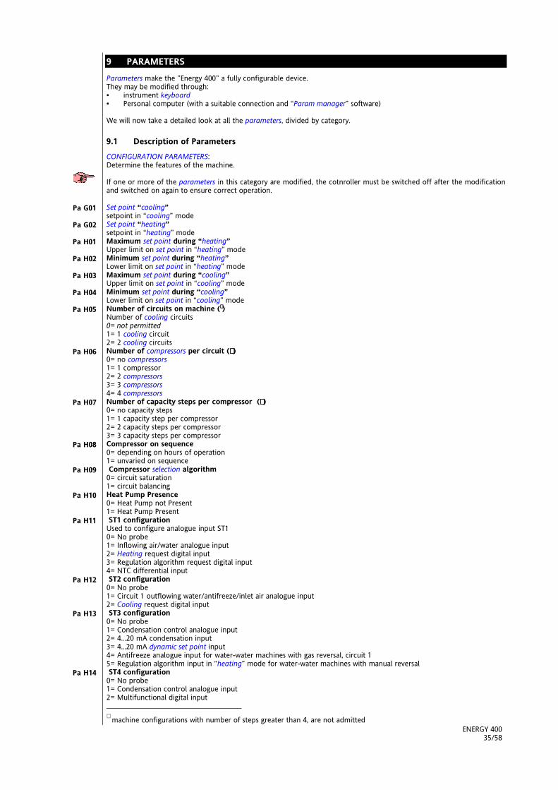
ENERGY 40035/58
9 PARAMETERSx
Parameters make the ”Energy 400” a fully configurable device.They may be modified through:• instrument keyboard• Personal computer (with a suitable connection and “Param manager” software)
We will now take a detailed look at all the parameters, divided by category.
9.1 Description of Parameters
CONFIGURATION PARAMETERS:Determine the features of the machine.
If one or more of the parameters in this category are modified, the cotnroller must be switched off after the modificationand switched on again to ensure correct operation.
Set point “cooling”setpoint in “cooling” modeSet point “heating”setpoint in “heating” modeMaximum set point during “heating”Upper limit on set point in “heating” modeMinimum set point during “heating”Lower limit on set point in “heating” modeMaximum set point during “cooling”Upper limit on set point in “cooling” modeMinimum set point during “cooling”Lower limit on set point in “cooling” modeNumber of circuits on machine (∗∗∗∗ )Number of cooling circuits0= not permitted1= 1 cooling circuit2= 2 cooling circuitsNumber of compressors per circuit (∗∗∗∗ )0= no compressors1= 1 compressor2= 2 compressors3= 3 compressors4= 4 compressorsNumber of capacity steps per compressor (∗∗∗∗ )0= no capacity steps1= 1 capacity step per compressor2= 2 capacity steps per compressor3= 3 capacity steps per compressorCompressor on sequence0= depending on hours of operation1= unvaried on sequence Compressor selection algorithm0= circuit saturation1= circuit balancingHeat Pump Presence0= Heat Pump not Present1= Heat Pump Present ST1 configurationUsed to configure analogue input ST10= No probe1= Inflowing air/water analogue input2= Heating request digital input3= Regulation algorithm request digital input4= NTC differential input ST2 configuration0= No probe1= Circuit 1 outflowing water/antifreeze/inlet air analogue input2= Cooling request digital input ST3 configuration0= No probe1= Condensation control analogue input2= 4...20 mA condensation input3= 4...20 mA dynamic set point input4= Antifreeze analogue input for water-water machines with gas reversal, circuit 15= Regulation algorithm input in “heating” mode for water-water machines with manual reversal ST4 configuration0= No probe1= Condensation control analogue input2= Multifunctional digital input ∗ machine configurations with number of steps greater than 4, are not admitted
Pa G01
Pa G02
Pa H01
Pa H02
Pa H03
Pa H04
Pa H05
Pa H06
Pa H07
Pa H08
Pa H09
Pa H10
Pa H11
Pa H12
Pa H13
Pa H14
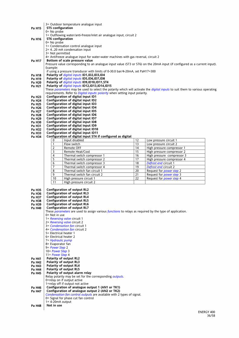
ENERGY 40036/58
3= Outdoor temperature analogue input ST5 configuration0= No probe1= Outflowing water/anti-freeze/inlet air analogue input, circuit 2 ST6 configuration0= No probe1= Condensation control analogue input2= 4...20 mA condensation input3= Not permitted4= Antifreeze analogue input for water-water machines with gas reversal, circuit 2 Bottom of scale pressure valuePressure value corresponding to an analogue input value (ST3 or ST6) on the 20mA input (if configured as a current input).Example: if using a pressure transducer with limits of 0-30.0 bar/4-20mA, set PaH17=300 Polarity of digital inputs ID1,ID2,ID3,ID4 Polarity of digital inputs ID5,ID6,ID7,ID8 Polarity of digital inputs ID9,ID10,ID11,ST4 Polarity of digital inputs ID12,ID13,ID14,ID15These parameters may be used to select the polarity which will activate the digital inputs to suit them to various operatingrequirements. Refer to Digital inputs: polarity when setting input polarity. Configuration of digital input ID1 Configuration of digital input ID2 Configuration of digital input ID3 Configuration of digital input ID4 Configuration of digital input ID5 Configuration of digital input ID6 Configuration of digital input ID7 Configuration of digital input ID8 Configuration of digital input ID9 Configuration of digital input ID10 Configuration of digital input ID11 Configuration of digital input ST4 if configured as digital
0 Input disabled 12 Low pressure circuit 11 Flow switch 13 Low pressure circuit 22 Remote OFF 14 High pressure compressor 13 Remote Heat/Cool 15 High pressure compressor 24 Thermal switch compressor 1 16 High pressure compressor 35 Thermal switch compressor 2 17 High pressure compressor 46 Thermal switch compressor 3 18 Defrost end circuit 17 Thermal switch compressor 4 19 Defrost end circuit 28 Thermal switch fan circuit 1 20 Request for power step 29 Thermal switch fan circuit 2 21 Request for power step 310 High pressure circuit 1 22 Request for power step 411 High pressure circuit 2
Configuration of output RL2 Configuration of output RL3 Configuration of output RL4 Configuration of output RL5 Configuration of output RL6 Configuration of output RL7These parameters are used to assign various functions to relays as required by the type of application.0= Not in use1= Reversing valve circuit 12= Reversing valve circuit 23= Condensation fan circuit 14= Condensation fan circuit 25= Electrical heater 16= Electrical heater 27= Hydraulic pump8= Evaporator fan9= Power Step 210= Power Step 311= Power Step 4 Polarity of output RL2 Polarity of output RL3 Polarity of output RL4 Polarity of output RL5 Polarity of output alarm relayRelay polarity may be set for the corresponding outputs.0=relay on if output active1=relay off if output not active Configuration of analogue output 1 (AN1 or TK1) Configuration of analogue output 2 (AN2 or TK2)Condensation fan control outputs are available with 2 types of signal.0= Signal for phase cut fan control1= 4-20mA output Not in use
Pa H15
Pa H16
Pa H17
Pa H18Pa H19Pa H20Pa H21
Pa H23Pa H24Pa H25Pa H26Pa H27Pa H28Pa H29Pa H30Pa H31Pa H32Pa H33Pa H34
Pa H35Pa H36Pa H37Pa H38Pa H39Pa H40
Pa H41Pa H42Pa H43Pa H44Pa H45
Pa H46Pa H47
Pa H48

ENERGY 40037/58
Selection of operating mode0= Selection from keyboard1= Selection from digital input Enable dynamic set pointIf enabled, this function permits automatic variation of the working set point depending on outdoor temperature or on a4-20mA analogue input. The parameter has no meaning if Pa H13≠3 or Pa H14≠3.0= Function disabled1= Function enabled Maximum dynamic set point offset in cooling modeThe maximum value that may be added to the set point in cooling mode (COO) when the DYNAMIC SET POINT function isenabled. Maximum dynamic set point offset in heating modeThe maximum value that may be added to the set point in heating mode (HEA) when the DYNAMIC SET POINT function isenabled. Outdoor temperature set point in cooling modeThe parameter is significant only if the dynamic set point function is enabled and probe ST4 is configured as an outdoortemperature probe. Outdoor temperature set point in heating modeThe parameter is significant only if the dynamic set point function is enabled and probe ST4 is configured as an outdoortemperature probe. Outdoor temperature differential in cooling modeThe parameter is significant only if the dynamic set point function is enabled and probe ST4 is configured as an outdoortemperature probe. Outdoor temperature differential in heating modeThe parameter is significant only if the set point function is enabled and probe ST4 is configured as an outdoortemperature probe. Offset ST1, Offset ST2, Offset ST3These parameters may be used to compensate the error that may occur between the temperature or pressure reading andthe actual temperature or pressure. Offset ST4 Offset ST5These parameters may be used to compensate the error that may occur between the temperature reading and the actualtemperature. Offset ST6This parameter may be used to compensate the error that may occur between the temperature (or pressure) reading andthe actual temperture or pressure. Mains frequencyMains frequency 50 HzMains frequency 60 Hz Selection °C or °F0= degrees °C1= degrees °F Family serial address, Device serial addressThese parameters may be used to address the device when connected to a personal computer or supervision system.Normally both are 0. User passwordMay be used to enter a password for access to level two parameters, and to copy parameters from the instrument to thecopy card. Copy card write passwordThe password that must be entered to copy parameters to the copy card. Presence of keyboard
ALARM PARAMETERS:
Low pressure pressure switch by-pass time.Determines the delay between starting up the compressor and starting up the low pressure digital alarm diagnostics.Expressed in seconds. Low pressure alarm events per hourUsed to set the number of low pressure digital alarm events per hour beyond which the system will switch from automaticreset to manual reset. Bypass pump activation flow switchDetermines the delay between activation of the hydraulic pump and activation of the flow switch alarm diagnostics.Expressed in seconds. Duration of active flow switch inputMay be used to set the amount of time for which the flow switch digital input must remain active to generate a flowswitch alarm. The timer starts after the flow switch by-pass time. Expressed in seconds. Duration of inactive flow switch inputMay be used to set the time for which the flow switch digital input must remain inactive to be included in thecorresponding alarm. Expressed in seconds. Number of flow switch alarms/hourMay be used to set the number of flow switch digital alarms per hour after which the alarm is switched from automatic tomanual reset. When this occurs, the hydraulic pump is deactivated. By-pass compressor thermal switch following compressor onDetermines the delay between compressor activation and activation of the compressor thermal switch digital diagnosticsalarm. Expressed in seconds.Compressor thermal switch alarm events per hour
Pa H49
Pa H50
Pa H51
Pa H52
Pa H53
Pa H54
Pa H55
Pa H56
Pa H57Pa H58Pa H59
Pa H60Pa H61
Pa H62
Pa H63
Pa H64
Pa H65Pa H66
Pa H67
Pa H68
Pa H68
Pa A01
Pa A02
Pa A03
Pa A04
Pa A05
Pa A06
Pa A07
Pa A08

ENERGY 40038/58
May be used to set a number of compressor thermal switch alarm events per hour beyond which the alarm is switchedfrom automatic to manual reset.Number of fan thermal switch events per hourMay be used to set a number of fan thermal events per hour beyond which the alarm is switched from automatic tomanual reset.Anti-freeze alarm by-passDetermines the delay between turning on the machine (selection of an operating mode or switch from OFF->ON) andactivation of the compressor thermal switch digital alarm diagnostics. Expressed in seconds. Active only in heating mode.Anti-freeze alarm set pointMay be used to set the temperature below which the anti-freeze alarm is triggered.Anti-freeze alarm hysteresisMay be used to set the differential value of the anti-freeze alarm.Anti-freeze alarm events per hourMay be used to set a number of anti-freeze alarm events per hour beyond which the alarm is switched from automatic tomanual reset.Analogue input high pressure/temperature activation set pointMay be used to set a condensation pressure/temperature value beyond which the high pressure alarm will be triggered.Analogue input high pressure/temperature hysteresisMay be used to set the differential for the analogue high pressure alarm.Analogue input high pressure/temperature activation bypassDetermines the delay after turning on of the first compressor in the cooling circuit and activation of the correspondinganalogue input low pressure/temperature analogue alarm diagnostics. Expressed in seconds.Analogue input low pressure/temperature activation set pointMay be used to set a temperature/pressure value below which the low pressure alarm will be triggered.Analogue input low pressure/temperature hysteresisMay be used to set the differential for the analogue low pressure/temperature alarm.Number of analogue input low pressure alarm events per hourMay be used to set a number of low pressure analogue alarm events per hour beyond which the alarm will be switchedfrom automatic to manual reset.Machine out of coolant differentialIf the difference between the absolute value of the set point and of the control probe exceeds this parameter, the machineout of coolant timer will start.Bypass machine out of coolantDetermines the delay between the turning on of the first compressor in the corresponding cooling circuit and activation ofthe machine out of coolant alarm diagnostics. Expressed in minutes.Duration of machine out of coolantDetermines the duration of the condition described under parameter Pa A20 beyond which the machine out of coolantalarm will be triggered.Machine out of coolant alarm triggeredEnables machine out of coolant alarm diagnostics0= diagnostics disabled1= diagnostics enabled Enable low pressure alarm during defrostingEnables the minimum alarm during defrosting.0= Low pressure alarm diagnostics disabled during defrosting1= Low pressure alarm diagnostics enabled during defrosting Input over-temperature set pointTemperature value ST1 above which the high temperature alarm E46 is triggered. Input over-temperature durationDetermines the duration of the condition described for parameter Pa A25 beyond which the input over-temperature alarmis triggered.
COMPRESSOR PARAMETERS
OFF-ON safety timeThe minimum amount of time that must pass between turning off the compressor and turning it on again. Expressed intens of seconds.ON-ON safety timeThe minimum amount of time that must pass between turning the compressor on and turning it on again. Expressed intens of seconds.Hysteresis regulation algorithm during coolingMay be used to select intervention differential in cooling mode.Hysteresis regulation algorithm during heatingMay be used to select intervention differential in heating mode. Regulation algorithm step intervention differentialMay be used to set a temperature differential in relation to the set point beyond which the second step is activated. Compressor on intervalMay be used to set a delay between turning on of two compressors. Compressor off intervalMay be used to set a delay between turning off of two compressors. Capacity step on intervalMay be used to set a delay between turning on of compressor and of capacity steps.
FAN CONTROL PARAMETERS:
Fan output configuration0 = proportional fan output (from 0 to 100% depending on parameters)1 = fan output “on-off”; in this mode the regulation algorithm performs the same calculation as in proportional fanoutput, but if the result is greater than 0, regulation algorithmoutput will be 100.
Pa A09
Pa A10
Pa A11
Pa A12
Pa A13
Pa A14
Pa A15
Pa A16
Pa A17
Pa A18
Pa A19
Pa A20
Pa A21
Pa A22
Pa A23
Pa A24
Pa A25
Pa A26
Pa C01
Pa C02
Pa C03
Pa C04
Pa C05
Pa C06
Pa C07
Pa C08
Pa F01

ENERGY 40039/58
2 = on-off operation in response to request from compressor. In this mode output is 0 if no compressor in the circuit ison, or 100% if at least one compressor in the circuit is on.Fan pick-up timeTime for which fan runs at maximum speed after starting up. Expressed in seconds/10.Fan phase shiftThis parameter may be used to calibrate fan control output in proportion to the type of fan in use, adjusting it to suit thefan’s typical current/voltage phase shift.Impulse duration of triac onMay be used to vary the length of the impulse from the triac command.Functioning in resposne to compressor request0= if compressor is off, fan is off1= condensation control independent of compressorMinimum speed during coolingMinimum value of proportional fan control during cooling. Expressed as a percentage of the power supply voltage, from 0to 100%,.Maximum silent speed during coolingMaximum value of proportional fan control during cooling. Expressed as a percentage of the power supply voltage, from 0to 100%,.Minimum fan speed temperature/pressure set point during coolingCondensation pressure/temperature value below which the fan runs at minimum cooling speed.Proportional band during coolingTemperature/pressure differential corresponding to change from minimum to silent maximum fan speed during cooling(Pa F07).Fan cut-off differentialCondensation temperature/pressure differential in relation to temperature/pressure set point (Pa F08 or pa F14) beyondwhich fan is cut off.Cut-off hysteresis.Condensation temperature/pressure differential for cut-off.Cut-off bypass timeDetermines the amount of time after fan start-up during which fan cut-off is excluded. Expressed in seconds.Maximum speed during coolingMay be used to set a speed step corresponding to a given temperature/pressure value in cooling mode.Maximum fan speed temperature/pressure during coolingCondensation pressure/temperature value corresponding to the fan speed set for par. Pa F13.Minimum speed during heatingMinimum proportional fan control value in heating mode. Expressed as a percentage of the power supply voltage, from 0to 100%,.Maximum silent speed during heatingMaximum value of proportional fan control during heating. Expressed as a percentage of the power supply voltage, from 0to 100%,.Minimum fan speed temperature/pressure set point during heatingCondensation temperature/pressure value above which the fan operates at minimum heating speed.Proportional band during heatingTemperature/pressure differential corresponding to a change from minimum to maximum silent fan speed during heating(Pa F16).Maximum speed during heatingMay be used to set a speed step corresponding to a given temperature/pressure value during heating.Maximum fan speed temperature/pressure set point during heatingCondensation temperature/pressure value corresponding to the fan speed set for Pa F19.Preventilation in cooling modeMay be used to set a preventilation time in cooling mode before compressor on.Combined or separate fan controlParameter F22 may be used to configure dual circuit machines with a single condenser.Parameter F22 condensation type0= separate condensers1= combined condenser.If Pa F22 = 0 the fans are independent and depend on condensation pressure/temperature and the status of thecompressors in the circuits. If Pa F22= 1 the outputs of the 2 fans are parallel and they are controlled:on the basis of the greater of the two circuit condensation probes in cooling modeon the basis of the smaller of the two circuit condensation probes in heating modeIf there is no condensation probe in one of the 2 circuits, a configuration alarm will be generated. Fan activation temperature/pressure set point during defrostingDuring defrosting, if temperature/pressure exceeds the “fan activation during defrosting” threshold (Pa F23) the fans willcome on at full power.Fan activation hysteresis during defrostingCondensation temperature/pressure differential for fan control during defrosting.Fan running time after defrost endIt’s the time the fans go on running after defrost time in order to quickly disperse the water in the battery.
PUMP PARAMETERS
Pump operating modeMay be used to determine pump operating mode:0=continuous operation1=operation in response to a request from the regulation algorithmDelay between pump ON and compressor ONMay be used to set a delay between starting a pump and starting a compressor, expressed in seconds.Delay between compressor OFF and pump OFFMay be used to set a delay between turning off a compressor and turning off a pump, expressed in seconds.
Pa F02
Pa F03
Pa F04
Pa F05
Pa F06
Pa F07
Pa F08
Pa F09
Pa F10
Pa F11
Pa F12
Pa F13
Pa F14
Pa F15
Pa F16
Pa F17
Pa F18
Pa F19
Pa F20
Pa F21
Pa F22
Pa F23
Pa F24
Pa F25
Pa P01
Pa P02
Pa P03

ENERGY 40040/58
ANTI-FREEZE/BOILER PARAMETERS
Configuration of electrical heaters in defrost modeDetermines electrical heater operation during defrosting0=come on only in response to a request from the regulation algorithm1=always on during defrostingConfiguration of electrical heaters on in cooling modeDetermines electrical heater operation in cooling mode0=off during cooling1=on during cooling (in response to anti-freeze electrical heater regulation algorithm)Configuration of electrical heaters on in heating modeDetermines electrical heater operation in heating mode0=off during heating1= on during cooling (in response to anti-freeze electrical heater regulation algorithm)Configuration of electrical heater 1 control probeConfiguration of electrical heater 2 control probeDetermines the control probes belonging to electrical heaters in heating mode0= Not present1=Control probe ST12=Control probe ST23= Control probe ST5Configuration of electrical heaters when OFF or on stand-byDetermines the status of electrical heaters when the instrument is OFF or on stand-by0=Always off when OFF or on stand-by1=On when OFF or on stand-by (in response to anti-freeze electrical heater control algorithm)Set point of anti-freeze electrial heater 1 in heating modeTemperature value below which anti-freeze electrical heater 1 comes on in heating mode.Set point of anti-freeze electrical heater 1 in cooling modeTemperature value below which anti-freeze electrical heater 1 comes on in cooling mode.Maximum set point of anti-freeze electrical heatersDetermines the maximum setting of the anti-freeze electrical heater set points.Minimum set point of anti-freeze electrical heatersDetermines the minimumsetting of the anti-freeze electrcial heater set points.Anti-freeze heater hysteresisAnti-freeze electrical heater control algorithm hysteresis.Set point of external anti-freeze electrical heatersTemperature below which anti-freeze electrical heaters in the secondary circuit come on in gas-inversion machine.Set point of electrical heater 2 in heating modeTemperature below which anti-freeze electrical heaters 2 come on in heating mode.Set point of electrical heater 2 in cooling modeTemperature below which anti-freeze electrical heaters 2 come on in cooling mode.Enable supplementary electrical heaters
DEFROST PARAMETERS::
Defrost enabled0= defrost function disabled1= defrost function enabledDefrost start temperature / pressureTemperature/pressure below which the defrost cycle is started.Defrost interval (response time)Duration for which probe remains below defrost start temperature/pressure, expressed in minutes.Defrost end temperature/pressureTemperature/pressure above which defrost ends.Maximum defrost time (time-out)Maximum duration of defrost in minutes.Compressor-reversing valve wait time (anti-bleeding)Wait time between compressor going off and reversal of the 4-way valve at the beginning of the defrost cycle.Drip timeWait time at the end of the defrost cycle between the compressor going off and the reversal of the 4-way valve.Delay between defrosting of circuits.Wait time between defrost end and next defrost start (independent by defrosting circuit)Output probe defrost circuit 1See table belowOutput probe defrost circuit 2See table below
Parameters value Description0 Defrost output on digital input1 Defrost output on ST32 Defrost output on ST43 Defrost output on ST6
Delay between defrost start and compressors on.It is the only safety time which regulates both compressors and capacity steps.
Pa r01
Pa r02
Pa r03
Pa r04Pa r05
Pa r06
Pa r07
Pa r08
Pa r09
Pa r10
Pa r11
Pa r12
Pa r13
Pa r14
Pa r15
Pa d01
Pa d02
Pa d03
Pa d04
Pa d05
Pa d06
Pa d07
Pa d08
Pa d09
Pa d10
Pa d11

ENERGY 40041/58
9.2 Parameters table
All ”Energy 400” parameters are listed in the table below.
CONFIGURATION PARAMETERS *Par. Description Value Limits Unit of meas.
Pa G01 Set Point “Cooling”Pa G02 Set Point “Heating”Pa H01 Maximum set point during heating Pa H02 ÷ 90.0 °CPa H02 Minimum set point during heating -40.0 ÷ Pa H01 °CPa H03 Maximum set point during cooling Pa H04 ÷ 90.0 °CPa H04 Minimum set point during cooling -40.0 ÷ Pa H03 °CPa H05 Number of circuits on machine 0 ÷ 2 NumPa H06 Number of compressors per circuit 0 ÷ 4 NumPa H07 Number of capacity steps per compressor 0 ÷ 3 NumPa H08 Compressors on sequence 0÷1 FlagPa H09 Circuit balancing 0÷1 FlagPa H10 Heat Pump presence 0 ÷ 1 FlagPa H11 Configuration ST1 0 ÷ 4 NumPa H12 Configuration ST2 0 ÷ 2 NumPa H13 Configuration ST3 0 ÷ 5 NumPa H14 Configuration ST4 0 ÷ 3 NumPa H15 Configuration ST5 0 ÷ 1 NumPa H16 Configuration ST6 0 ÷ 4 NumPa H17 Bottom of scale pressure value 0-350 KPa*10Pa H18 Polarity ID1 ID2 ID3 ID4 0 ÷ 15 NumPa H19 Polarity ID5 ID6 ID7 ID8 0 ÷ 15 NumPa H20 Polarity ID9 ID10 ID11 ST4 0 ÷ 15 NumPa H21 Polarity ST1 0 ÷ 1 FlagPa H22 Polarity ST2 0 ÷ 1 FlagPa H23 Configuration ID1 0 ÷ 22 NumPa H24 Configuration ID2 0 ÷ 22 NumPa H25 Configuration ID3 0 ÷ 22 NumPa H26 Configuration ID4 0 ÷ 22 NumPa H27 Configuration ID5 0 ÷ 22 NumPa H28 Configuration ID6 0 ÷ 22 NumPa H29 Configuration ID7 0 ÷ 22 NumPa H30 Configuration ID8 0 ÷ 22 NumPa H31 Configuration ID9 0 ÷ 22 NumPa H32 Configuration ID10 0 ÷ 22 NumPa H33 Configuration ID11 0 ÷ 22 NumPa H34 Configuration ST4 if digital input 0 ÷ 22 NumPa H35 Configuration relay 2 0 ÷ 11 NumPa H36 Configuration relay 3 0 ÷ 11 NumPa H37 Configuration relay 4 0 ÷ 11 NumPa H38 Configuration relay 5 0 ÷ 11 NumPa H39 Configuration relay 6 0 ÷ 11 NumPa H40 Configuration relay 7 0 ÷ 11 NumPa H41 Polarity RL2 0 ÷ 1 FlagPa H42 Polarity RL3 0 ÷ 1 FlagPa H43 Polarity RL4 0 ÷ 1 FlagPa H44 Polarity RL5 0 ÷ 1 FlagPa H45 Alarm relay polarity 0 ÷ 1 FlagPa H46 Configuration fan 1 output 0 ÷ 1 FlagPa H47 Configuration fan 2 output 0 ÷ 1 FlagPa H48 Free 0 ÷ 1 FlagPa H49 Selection of operating mode 0 ÷ 1 FlagPa H50 Enable dynamic set point 0 ÷ 1 FlagPa H51 Offset of dynamic set point during cooling -50.0 ÷ 80.0 °CPa H52 Offset of dynamic set point during heating -50.0 ÷ 80.0 °CPa H53 Dynamic outdoor temp. set point during cooling -127 ÷ 127 °CPa H54 Dynamic outdoor temp. set point during heating -127 ÷ 127 °CPa H55 Delta dynamic outdoor temp. set point during cooling -50.0 ÷ 80.0 °CPa H56 Delta dynamic outdoor temp. set point during heating -50.0 ÷ 80.0 °CPa H57 Offset ST1 -12.7 ÷ 12.7 °CPa H58 Offset ST2 -12.7 ÷ 12.7 °CPa H59 Offset ST3 -127 ÷ 127 °C/10-Kpa*10Pa H60 Offset ST4 -12.7 ÷ 12.7 °CPa H61 Offset ST5 -12.7 ÷ 12.7 °CPa H62 Offset ST6 -127 ÷ 127 °C/10-Kpa*10Pa H63 0=50 Hz 1=60 Hz 0 ÷ 1 FlagPa H64 0= °C 1=°F 0 ÷ 1 FlagPa H65 Family serial address 0 ÷ 14 Num.
Configurationparameters

ENERGY 40042/58
Pa H66 Device serial address 0 ÷ 14 Num.Pa H67 User password 0 ÷ 255 Num.Pa H68 Copy card password 0 ÷ 255 Num.Pa H69 Keyboard Presence 0/1 Flag
* If parameters in this category are modified, the controller must be turned off and on again to ensure correctfunctioning.
ALARM PARAMETERSPar. Description Value Limits Unit of
measurementPa A01 Low pressure switch bypass time after compressor on 0 ÷ 255 SecondsPa A02 Low pressure alarm events per hour 0 ÷ 255 NumPa A03 Flow switch bypass time after pump on 0 ÷ 255 SecondsPa A04 Duration of active flow switch input 0 ÷ 255 SecondsPa A05 Duration of inactive flow switch input 0 ÷ 255 SecondsPa A06 Number of flow switch alarm events per hour 0 ÷ 255 NumPa A07 Bypass compressor thermal switch from compressor on 0 ÷ 255 SecondsPa A08 Number of compressors 1 + 2 thermal switch
alarms/hour0 ÷ 255 Num
Pa A09 Number of fan thermal switch alarm events/hour 0 ÷ 255 NumPa A10 Anti-freeze alarm bypass after ON-OFF 0 ÷ 255 MinutesPa A11 Anti-freeze alarm activation set point -127 ÷ 127 °CPa A12 Hysteresis of anti-freeze alarm 0 ÷ 25.5 °CPa A13 Anti-freeze alarm events/hour 0 ÷ 255 NumPa A14 Analogue input high pressure/temperature activation set
point0 ÷ 900 °C/10 – Kpa*10
Pa A15 Analogue input high pressure hysteresis 0 ÷ 255 °C/10 – Kpa*10Pa A16 Analogue input low pressure activation bypass 0 ÷ 255 SecondsPa A17 Analogue input low pressure activation set point -500 ÷ 800 °C/10 – Kpa*10Pa A18 Analogue input low pressure hysteresis 0 ÷ 255 °C/10 – Kpa*10Pa A19 Analogue input low pressure alarm events per hour 0 ÷ 255 NumPa A20 Machine out of coolant differential 0 ÷ 255 °CPa A21 Machine out of coolant bypass 0 ÷ 255 MinutesPa A22 Machine out of coolant duration 0 ÷ 255 MinutesPa A23 Machine out of coolant alarm triggered 0 ÷ 1 FlagPa A24 Enable low pressure alarm during defrost 0 ÷ 1 FlagPa A25 Input over-temperature set point 0 ÷ 255 °CPa A26 Input over-temperature duration 0 ÷ 255 S*10
COMPRESSOR PARAMETERSPar. Description Value Limits Unit of
measurementPa C01 ON-OFF safety time 0 ÷ 255 Seconds*10Pa C02 ON-ON safety time 0 ÷ 255 Seconds*10Pa C03 Hysteresis regulation algorithm during cooling 0 ÷ 25.5 °CPa C04 Hysteresis regulation algorithm during heating 0 ÷ 25.5 °CPa C05 Regulation algorithm step intervention delta 0 ÷ 25.5 °CPa C06 Compressor – compressor on interval 0 ÷ 255 SecondsPa C07 Compressor – compressor off interval 0 ÷ 255 SecondsPa C08 Capacity step on interval 0 ÷ 255 Seconds
FAN CONTROL PARAMETERSPar. Description Value Limits Unit of
measurementPa F01 Fan output mode 0 ÷ 2 Num.Pa F02 Fan pick-up time 0 ÷ 255 Seconds/10Pa F03 Fan phase shift 0 ÷ 100 µSeconds*200Pa F04 Impulse duration of triak on 0 ÷ 255 µSeconds*200Pa F05 Functioning in response to compressor request 0 ÷ 1 FlagPa F06 Minimum speed during cooling 0 ÷ 100 %Pa F07 Maximum silent speed during cooling 0 ÷ 100 %Pa F08 Minimum fan speed temperature/pressure set point
during cooling-500 ÷ 800 °C/10 - Kpa*10
Pa F09 Prop. band during cooling 0 ÷ 255 °C/10 - Kpa*10Pa F10 Delta cut-off 0 ÷ 255 °C/10 - Kpa*10Pa F11 Cut-off hysteresis. 0 ÷ 255 °C/10 - Kpa*10Pa F12 Bypass time cut-off 0 ÷ 255 SecondsPa F13 Max speed during cooling 0 ÷ 100 %Pa F14 Maximum fan speed temperature/pressure set point
during cooling-500 ÷ 800 °C/10 - Kpa*10
Pa F15 Minimum speed during heating 0 ÷ 100 %Pa F16 Maximum silent speed during heating 0 ÷ 100 %Pa F17 Minimum fan speed temperature/pressure set point
during heating-500 ÷ 800 °C/10 - Kpa*10
Pa F18 Prop. band during heating 0 ÷ 255 °C/10 - Kpa*10Pa F19 Maximum fan speed during heating 0 ÷ 100 %
Alarm parameters
Compressorparameters
Fan controlparameters

ENERGY 40043/58
Pa F20 Maximum fan speed temperature/pressure set pointduring heating
-500 ÷ 800 °C/10 - Kpa*10
Pa F21 Preventilation in cooling mode 0 ÷ 255 SecondsPa F22 Combined or separate fan control 0 ÷ 1 FlagPa F23 Fan activation temperature/pressure set point during
defrosting-500 ÷ 800 °C/10 - Kpa*10
Pa F24 Fan activation hysteresis during defrosting 0 ÷ 255 °C/10 - Kpa*10Pa F25 Fan running time after defrost end 0 ÷ 255 Seconds
PUMP PARAMETERSPar. Description Value Limits Unit of
measurementPa P01 Pump operating mode 0 ÷ 1 FlagPa P02 Delay between pump ON and compressor ON 0 ÷ 255 SecondsPa P03 Delay between compressor OFF and pump OFF 0 ÷ 255 Seconds
ELECTRICAL HEATER PARAMETERSPar. Description Value Limits Unit of
measurementPa r01 Configuration of electrical heaters in defrost mode 0 ÷ 1 FlagPa r02 Configuration of electrical heaters on in cooling mode 0 ÷ 1 FlagPa r03 Configuration of electrical heaters on in heating mode 0 ÷ 1 FlagPa r04 Configuration of electrical heater 1 control probe 0 ÷ 3 NumPa r05 Configuration of electrical heater 2 control probe 0 ÷ 3 NumPa r06 Configuration of electrical heaters when OFF or on
STAND-BY0 ÷ 1 Flag
Pa r07 Set point of electrical heater 1 in heating mode Pa 10 ÷ Pa 09 °CPa r08 Set point of electrical heater 1 in cooling mode Pa 10 ÷ Pa 09 °CPa r09 Max. set point electrical heaters Pa 10 ÷ 127 °CPa r10 Min. set point electrical heaters -127 ÷ Pa 09 °CPa r11 hysteresis of anti-freeze heaters 0 ÷ 25.5 °CPa R12 Set point of external anti-freeze electrical heaters Pa 10 ÷ Pa 09 °CPa r13 Set point of electrical heater 2 in heating mode Pa 10 ÷ Pa 09 °CPa r14 Set point of electrical heater 2 in cooling mode Pa 10 ÷ Pa 09 °CPa r15 Enable supplementary electrical heaters 0 ÷ 1 FlagPa r16 Delta of activation of supplementary heater 1 0 ÷ 25.5 °CPa r17 Delta of activation of supplementary heater 2 0 ÷ 25.5 °C
DEFROST PARAMETERSPar. Description Value Limits Unit of
measurementPa d01 Defrost enabled 0 ÷ 1 FlagPa d02 Defrost start temperature/pressure -500 ÷ 800 °C/10 - Kpa*10Pa d03 Defrost interval 0 ÷ 255 MinutesPa d04 Defrost end temperature/pressure -500 ÷ 800 °C/10 – Kpa*10Pa d05 Maximum defrost time 0 ÷ 255 MinutesPa d06 Compressor-reversing valve wait time 0 ÷ 255 SecondsPa d07 Drip time 0 ÷ 255 SecondsPa d08 Delay between defrosting of circuits 0 ÷ 255 Seconds * 10Pa d09 Output probe defrost circuit 1 0 ÷ 3 NumPa d10 Output probe defrost circuit 2 0 ÷ 3 NumPa d11 Delay in compressors on in defrost mode 0 ÷ 255 Seconds
EXTENSION PARAMETERSPar. Description Value Limits Unit of
measurementPa N01 Polarity of ID12 ID13 ID14 ID15 0 ÷ 5 FlagPa N02 Configuration ID12 0 ÷ 22 NumPa N03 Configuration ID13 0 ÷ 22 NumPa N04 Configuration ID14 0 ÷ 22 NumPa N05 Configuration ID15 0 ÷ 22 NumPa N06 Configuration relay 9 0 ÷ 11 NumPa N07 Configuration relay 10 0 ÷ 11 Num
Pump parameters
Electrical heaterparameters
Defrostparameters
Extensionparameters

ENERGY 40044/58
<IMG INFO>36,75
<IMG INFO>28,329,31
10 DIAGNOSTICSx
“Energy 400” can perform full systems diagnostics and signal a series of alarms.Alarm trigger and reset modes are set using parameters Pa A01 – Pa A26.For some alarms the signal will not be given for a certain amount of time, determined by a parameter.For some alarms the number of alarm events is counted; if the number of alarm events in the past hour exceeds a certainthreshold set by a parameter, the alarm will switch from automatic to manual reset.Alarms are sampled every 226 seconds;Example: if the number of events/hour is set to 3, the duration of an alarm must fall between 2*226 seconds and 3*226seconds for the alarm to be switched from automatic to manual reset.
If an alarm is triggered more than once within one sampling period (226 seconds), only one alarm will be counted.
Alarms with manual reset are reset by pressing the ON-OFF button and releasing
Manual reset shuts down corresponding loads and requires an operator to intervene (reset the alarm using the ON-OFFcontrol).Manual reset alarms are used mainly to identify problems which could result in damage to the system
10.1 List of alarms
When an alarm is triggered, two things occur:• The corresponding loads are shut down• The alarm appears on the keyboard display
The alarm message consists of a code with the format “Enn” (where nn is a 2-digit number identifying the type of alarm,such as: E00, E25, E39….).All possible alarms are listed in the table below, along with their codes and the corresponding loads that will be shutdown:
Alarms
Alarm events perhour
Time225 s 225 s 225 s 225 s
1 2 3Counter
Alarm
Automatic reset Manual reset
Alarm sampling

ENERGY 40045/58
LOADS SHUT DOWNCODE MESSAGE DESCRIPTIONCOMP.1 COMP.2 COMP.3 COMP.4 FAN1 FAN2 PUMP RES.1 RES.2
E00 Remote off • All loads will be shut down;• Triggered by the digital input configured as “Remote OFF”
(refer to digital inputs)
YES YES YES YES YES YES YES YES YES
E01 High pressure circuit 1 • Compressors in circuit 1 will be shut down;• Triggered by the digital input configured as “High pressure
circuit 1” (refer to digital inputs)
YES YES1 YES1 YES1
E02 Low pressure circuit 1 • Compressors in circuit 1 will be shut down; also condenserfans if condensation is separate for the 2 circuits (refer tocombined or separate condensation);
• Triggered by the digital input configured as “Low pressurecircuit 1” (refer to digital inputs);
• Automatically reset unless alarm events per hour reaches thevalue of parameter Pa A02, after which manually reset;
• Inactive during timer Pa A01 after compressor on or reversalof 4-way valve (reversing valve) in circuit 1
YES YES1 YES1 YES1 YES4
E03 Thermal switchprotection compressor 1
• Compressor 1 will be shut down;• Triggered by the digital input configured as “Thermal switch
compressor 1” (refer to digital inputs);• Automatically reset until alarm events per hour reaches the
value of parameter Pa A07, after which manually reset;• Inactive during timer Pa A08 after compressor on.
YES
E04 Thermal switchprotection condenserfan circuit 1
• Fans and compressors in circuit 1 will be shut down; if the 2circuits are set up for combined condensation, (refer tocombined or separate condensation) compressors in circuit 2will also be shut down;
• Triggered by the digital input configured as “Thermal switchfan circuit 1” (refer to digital inputs);
• Automatically reset until alarm events per hour reaches thevalue of parameter Pa A09, after which manually reset;
YES YES1 YES1 -
YES2YES1 -
YES2YES YES2
E05 Anti-freeze circuit 1 • Fans and compressors in circuit 1 will be shut down;• Active if analogue probe ST2 (refer to analogue inputs) is
configured as anti-freeze probe (Pa H12 = 1);• Triggered when probe ST2 detects a value lower than Pa A11;• Turned off if probe ST2 detects a value greater than Pa A11 +
Pa A12;• Automatically reset until alarm events per hour reaches the
value of parameter Pa A13,after which manually reset;• Inactive during timer Pa A10 after Energy 400 is turned on
with the On-OFF key (refer to keyboard) or from the digitalinput ON-OFF (refer to digital inputs) or when heating modeis started.
YES YES YES YES1 YES YES
E06 Probe ST2 fault • All loads will be shut down;• Triggered if probe ST2, configured as an analogue input,
shorts or is cut off or probe limits are exceeded (-50°C..100°C).
YES YES YES YES YES YES YES YES YES
E07 Probe ST3 fault • All loads will be shut down;• Triggered if probe ST3, configured as an analogue input,
shorts or is cut off or probe limits are exceeded (-50°C..100°C).
YES YES YES YES YES YES YES YES YES
Tabella Allarmi

ENERGY 40046/58
LOADS SHUT DOWNCODE MESSAGE DESCRIPTIONCOMP.1 COMP.2 COMP.3 COMP.4 FAN1 FAN2 PUMP RES.1 RES.2
E09 High pressurecompressor 1
• Compressor 1 will be shut down;• Triggered by the digital input configured as “High pressure
compressor 1” (refer to digital inputs);• Always manually reset
YES
E11 High pressure circuit 1on analog input
• Compressors in circuit 1 will be shut down;• Active if analog probe ST3 or ST4 (refer to analog inputs) is
configured as pressure probe;• Active when the pressure probe (ST3/ST4) detects a value
greater then Pa A14;• Inactive if the probe detects a value lower then Pa A14 – Pa
A15;
YES YES1 YES1 YES1
E12 Low pressure circuit 1on analog input
• Compressors in circuit 1 will be shut down, as well ascondenser fans if the 2 circuits have separate condensation(refer to combined or separate condensation);
• Active if the analog probe ST6 (refer to analog inputs) isconfigured as pressure probe;
• Active when the pressure probe ST6 detects a value lowerthen Pa A17;
• Inactive if the probe detects a value greater then Pa A17 – PaA18;
• Automatically reset until alarm events per hour reaches thevalue of parameter Pa A19, after which manually reset;
• Inactive during timer Pa A16 after compressor on or reversalof 4-way valve (reversing valve) of circuit 1
YES YES1 YES1 YES1 YES4
E13 Thermal switchprotection compressor 2
• Compressor 2 will be shut down;• Triggered by the digital input configured as “Thermal switch
compressor 2” (refer to digital inputs);• Automatically reset until alarm events per hour reach the value
of parameter Pa A07, after which manually reset;• Inactive during timer Pa A08 after compressor is turned on.
YES
E19 High pressurecompressor 2
• Compressor 2 will be shut down;• Triggered by the digital input configured as “High pressure
compressor 1” (refer to digital inputs);• Always manually reset
YES
E21 High pressure circuit 2 • Compressors in circuit 2 will be shut down;• Triggered by the digital input configured as “High pressure
circuit 2” (refer to digital inputs)
YES5 YES5
E22 Low pressure circuit 2 • Compressors in circuit 2 will be shut down, as well ascondenser fans if the 2 circuits have separate condensation(refer to combined or separate condensation);
• Triggered by the digital input configured as “Low pressurecircuit 2” (refer to digital inputs);
• Automatically reset until alarm events per hour reaches thevalue of parameter Pa A02, after which manually reset;
• Inactive during timer Pa A01 after compressor on or reversalof 4-way valve (reversing valve) of circuit 1
YES YES YES4
E23 Thermal switchprotection compressor 3
• Compressor 3 will be shut down;• Triggered by the digital input configured as “Thermal switch
compressor 3” (refer to digital inputs);• Automatically reset until alarm events per hour reach value of
YES

ENERGY 40047/58
LOADS SHUT DOWNCODE MESSAGE DESCRIPTIONCOMP.1 COMP.2 COMP.3 COMP.4 FAN1 FAN2 PUMP RES.1 RES.2
parameter Pa A07, after which manually reset;• Inactive during timer Pa A08 after compressor on.
E24 Thermal switchprotection condenserfan circuit 2
• Fans and compressors in circuit 2 will be shut down; if the 2circuits have combined condensation (refer to combined orseparate condensation) the compressors in circuit 1 will alsobe shut down;
• Triggered by the digital input configured as “Thermal switchcircuit 2 fan” (refer to digital inputs);
• Automatically reset until alarm events per hour reaches valueof parameter Pa A09, after which manually reset;
YES2 YES2 YES YES YES2 YES
E25 Anti-freeze circuit 2 • Fans and compressors will be shut down;• Active if analogue probe ST5 (refer to analogue inputs) is
configured as anti-freeze probe (Pa H15 = 1);• Triggered when probe ST5 detects a value below Pa A11;• Turns off when probe ST5 detects a value above Pa A11 + Pa
A12;• Automatically reset until alarm events per hour reaches value
of parameter Pa A13, after which manually reset;• Inactive during timer Pa A10 after turning on Energy 400 using
On-OFF key (refer to keyboard) or digital input ON-OFF (referto digital inputs) or start of heating mode.
YES YES YES YES YES YES
E26 Probe ST5 fault • All loads will be shut down;• Triggered if probe ST5, configured as an analogue input,
shorts or is cut off or probe limits are exceeded (-50°C..100°C).
YES YES YES YES YES YES YES YES YES
E27 Probe ST6 fault • All loads will be shut down;• Triggered if probe ST6, configured as an analogue input,
shorts or is cut off or probe limits are exceeded (-50°C..100°C).
YES YES YES YES YES YES YES YES YES
E29 High pressurecompressor 3
• Compressor 3 will be shut down;• Triggered by the digital input configured as “High pressure
compressor 3” (refer to digital inputs);• Always manually reset
YES
E31 High pressure circuit 2on analog input
• Compressors in circuit 2 will be shut down;• Active if analog probe ST3/ST4 (refer to analog inputs) is
configured as pressure probe;• Active when the pressure probe (ST3/ST4) detects a value
greater then Pa A14;• Inactive if the probe detects a value lower then Pa A14 – Pa
A15;
YES5 YES5
E32 Low pressure circuit 2on analog input
• Compressors in circuit 2 will be shut down, as well ascondenser fans if the 2 circuits have separate condensation(refer to combined or separate condensation);
• Active if the analog probe ST6 (refer to analog inputs) isconfigured as pressure probe;
• Active when the pressure probe ST6 detects a value lowerthen Pa A17;
• Inactive if the probe detects a value greater then Pa A17 – PaA18;
• Automatically reset until alarm events per hour reaches the
YES YES YES4

ENERGY 40048/58
LOADS SHUT DOWNCODE MESSAGE DESCRIPTIONCOMP.1 COMP.2 COMP.3 COMP.4 FAN1 FAN2 PUMP RES.1 RES.2
value of parameter Pa A19, after which manually reset;• Inactive during timer Pa A16 after compressor on or reversal
of 4-way valve (reversing valve) of circuit 2E33 Thermal switch
protection compressor 4• Compressor 4 will be shut down;• Triggered by the digital input configured as “Thermal switch
compressor 4” (refer to digital inputs);• Automatically reset until alarm events per hour reaches the
value of parameter Pa A07, after which manually reset;• Inactive during timer Pa A08 after compressor on.
YES
E39 High pressurecompressor 4
• Compressor 4 will be shut down;• Triggered by the digital input configured as “High pressure
compressor 4” (refer to digital inputs);• Always manually reset
YES
E40 Probe ST1 fault • All loads will be shut down;• Triggered if probe ST1, configured as an analogue input,
shorts or is cut off or probe limits are exceeded (-50°C..100°C).
YES YES YES YES YES YES YES YES YES
E41 Flow switch • All compressors, fans and pump will be cut off if manuallyreset;
• Triggered if the digital input configured as “Flow switch”(refer to digital inputs) remains active for an amount of timeequal to Pa A04;
• Goes off if the digital input configured as “Flow switch” (referto digital inputs) remains inactive for an amount of time equalto Pa A05;
• Automatically reset until alarm events per hour reaches thevalue of parameter Pa A06 , after which manually reset;
• Inactive during timer Pa A03 following pump on.
YES YES YES YES YES YES YES3
E42 Probe ST4 fault • All loads will be shut down;• Triggered if probe ST4, configured as an analogue input,
shorts, is cut off, or probe limits are exceeded (-50°C.. 100°C).
YES YES YES YES YES YES YES YES YES
E43 Anti-freeze externalcircuit 1,2
• Fans and compressors will be shut down;• Active if analogue probe ST6 and/or ST3 (refer to analogue
inputs) is configured as external anti-freeze probe (Pa H13 =4, Pa H16=4);
• Triggered when probe ST3 and/or ST6 detects a value belowPa A11;
• Turns off when probe ST3 and/or ST6 detects a value abovePa A11 + Pa A12;
• Automatically reset until alarm events per hour reaches valueof parameter Pa A13, after which manually reset;
• Inactive during timer Pa A10 after turning on Energy 400 usingOn-OFF key (refer to keyboard) or digital input ON-OFF (referto digital inputs) or start of heating mode.
YES YES YES YES YES YES
E44 Machine out of coolant • In all working modes, except if the boiler is active and duringdefrost, the machine is checked to identify circuit failures. Forexample: gas flooding, broken inversion valve in heat pumpmachines, compressor power phases exchange.
• The regulator is active if Pa A23=1 and ST2 is configured aswater output probe. An alarm arises if one of the following
YES YES YES YES YES YES

ENERGY 40049/58
<IMG INFO>36,75
LOADS SHUT DOWNCODE MESSAGE DESCRIPTIONCOMP.1 COMP.2 COMP.3 COMP.4 FAN1 FAN2 PUMP RES.1 RES.2
conditions lasts for a minimum time of Pa A22:• ST2-ST1(or ST3)<Pa A20 in heat pump configuration,• ST1(or ST3)-ST2<Pa A20 in cooling configuration.• The gas flooding alarm always needs a manual reset.• Time count resets with each mode change or if all the
compressors are off. After a compressor start, the alarm isignored for a time of Pa A21.
E45 Configuration error • All loads will be shut down;• Triggered if at least one of the following conditions apply:• H11= 2 (ST1 configured as request for heating), H12= 2 (ST2
configured as request for cooling) and both inputs are active.• Sum of compressors and capacity steps on machine exceeds 4• The keyboard is declared present (Pa H69=1) and there is no
communication between the keyboard and the basic unit.
YES YES YES YES YES YES YES YES YES
E46 High temperatureregulation algorithm
• All loads will be shut down except the pump;• Triggered if probe ST1 (refer to analogue inputs) has a value
exceeding Pa A25 for an amount of time exceeding Pa 26 incooling mode;
• Goes off if probe ST1 (refer to analogue inputs) has a valuelower than Pa A25 – Pa A12;
• Automatically reset.
YES YES YES YES YES YES YES YES
1 If it belongs to circuit 12 If combined condensation system3 Only if manual reset4 With separate ventilation5 If it belongs to circuit 2
outputs defined as capacity steps will go off if there is an alarm for the compressor to which they belong

ENERGY 40050/58
The tables below list alarms by type (digital or analogue).
TABLE OF DIGITAL ALARMS:
Alarm name Bypass trigger event Bypass time Triggerduration
Deactivationduration
N. alarmevents/hour
Compressor 1,2,3,4 highpressure alarm
None absent absent absent Manual reset
High pressure circuitalarm
None absent absent absent Manual reset
Low pressure alarm A compressor comingon in the circuit orreversal of 4-wayvalve
Pa A01 absent absent Pa A02
Flow switch alarm Pump coming on Pa A03 Pa A04 Pa A05 Pa A06Compressor 1,2,3,4thermal switch alarm
Compressor comingon
Pa A07 absent absent Pa A08
Fan 1,2 thermal switchalarm
None absent absent absent Pa A09
TABLE OF ANALOGUE ALARMS:
Alarm name Event Bypasstime
Triggerset point
Hysteresis N. alarmevents/hour
Regulation probe
Anti-freezealarm circuit 1
On Off, inputin heatingmode, remoteon off
Pa A10 Pa A11 Pa A12positive
Pa A13 ST2 if configuration parameter PaH12 = 1, otherwise alarm isinactive
Anti-freezealarm circuit 2
On Off, inputin heatingmode, remoteon off
Pa A10 Pa A11 Pa A12positive
Pa A13 ST5 if configuration parameter PaH15 = 1, otherwise alarm isinactive
External anti-freeze alarmcircuit 1/2
On Off, inputin heatingmode, remoteon off
Pa A10 Pa A11 Pa A12positive
Pa A13 ST3/ST6 if configurationparameter Pa H13/H16 = 4,otherwise alarm is inactive
Low pressure/lowtemperaturecondensationalarm circuit 1
Compressorturned on orreversal of 4-way valve
Par A16 Pa A17 Pa A18positive
Pa A19 ST3 se Pa H13=1 or 2 or else ST4if Pa H14 = 1, otherwise alarm isinactive
Low pressure/lowtemperaturecondensationalarm circuit 2
Compressorturned on orreversal of 4-3way valve
Par A16 Pa A17 Pa A18positive
Pa A19 ST6 if Pa H16=1, otherwise alarmis inactive
High pressure/hightemperaturecondensationalarm circuit 1
None absent Pa A14 Pa A15negative
Manual reset ST3 if Pa H13=1 or 2, or ST4 if PaH14 = 1; otherwise alarm isinactive
High pressure/hightemperaturecondensationalarm circuit 2
None absent Pa A14 Pa A15negative
Manual reset ST6 if Pa H16=1 or 2, otherwisealarm is inactive
Hightemperatureregulationalgorithm alarm
None absent Pa A25 Pa A12negative
Automaticreset
ST1
Digital alarms
Analogue alarms

ENERGY 40051/58
11 TECHNICAL FEATURESx
11.1 Technical data
Typical Min. Max.Power supply voltage 12V~ 10V~ 14V~Power supply frequency 50Hz/60Hz --- ---Power 5VA --- ---Insulation class 1 --- ---Protection grade Front panel
IP0--- ---
Operating temperature 25°C 0°C 60°COperating humidity (non-condensing) 30% 10% 90%
Storage temperature 25°C -20°C 85°CStorage humidity (non-condensing) 30% 10% 90%
11.2 Electromechanical features
110/230 V digital outputs n° 8 5 A resistive relays; ¼ hp 230VAC; 1/8 hp 125VAC (on base module)the total amout of relays current must be lower than 10An° 2 5 A resistive relays; ¼ hp 230VAC; 1/8 hp 125VAC (on expansion module)
Analogue outputs n° 2 triac piloting outputs or configurable 4-20 mA outputsAnalogue inputs n° 4 NTC R25 10KΩ
n° 2 configurable input or 4-20mA o r NTC R25 10KΩDigital inputs N° 11 voltage-free digital inputs (on base module)
N° 4 voltage-free digital inputs (on expansion module)Terminals and connectors N° 1 10-way high voltage connectors, step 7.5
N° 2 16-way rapid clamp connectors for low voltage, step 4.2, AWG 16-28N° 1 p2.5 5–way connector for remote control and programming withexternal copy card, AWG 24-30n° 1 20-way connector for connection of expansionn° 1 3-way screw terminal for remote keyboard
Serial ports n° 1 9600 serial portn° 1 2400 serial port
The instrument must be powered with a suitable current transformer with the following features:
• Primary voltage: 230V~±10%; 110V~±10%• Secondary voltage: 12V~• Power supply frequency: 50Hz; 60Hz• Power: 11VA;
11.3 Regulations
The product complies with the following European Community Directives:• Council Directive 73/23/CEE and subsequent modifications• Council directive 89/336/CEE and subsequent modifications
and complies with the following harmonised regulations:• LOW VOLTAGE: EN60335 as far as applicable• EMISSION: EN50081-1 (EN55022)• IMMUNITY: EN50082-1 (IEC 1000-4-2/3/4/5)
currenttransformer

ENERGY 40052/58
12 USE OF THE DEVICEx
12.1 Permitted use
This product is used to control single and dual circuit chillers and heat pumps.
To ensure safety, the controller must be installed and operated in accordance with the instructions supplied, and access tohigh voltage components must be prevented under regular operating conditions. The device shall be properly protectedagainst water and dust and shall be accessible by using a tool only. The device is suitable for incorporation in a householdappliance and/or similar air conditioning device.According to the reference regulations, it is classified:• In terms of construction, as an automatic electronic control device to be incorporated with independent assembly or
integrated;• In terms of automatic operating features, as a type 1 action control device, with reference to manufacturing
tolerances and drifts;• As a class 2 device in relation to protection against electrical shock;• As a class A device in relation to software structure and class.
12.2 Forbidden use
Any use other than the permitted use is forbidden.Please note that relay contacts supplied are functional and are subject to fault (in that they are controlled by an electroniccomponent and be shorted or remain open); protection devices recommended by product standards or suggested bycommon sense in response to evident safety requirements shall be implemented outside of the instrument.

ENERGY 40053/58
13 RESPONSIBILITY AND RESIDUAL RISKSx
Microtech shall not be held liable for any damage incurred as a result of:• installation/use other than those intended, and, in particular, failure to comply with the safety instructions specified
by applicable regulations and/or provided in this document;• use with equipment which does not provide adequate protection against electric shocks, water and dust under the
effective conditions of installation;• use with equipment which permits access to hazardous parts without the use of tools;• installation/use with equipment which does not comply with current regulations and legislation.

ENERGY 40054/58
14 GLOSSARYx
Multiple inputs with an OR relationship to one another are equivalent to a single input with the following status:• Active if at least one input is active• Inactive if no input is active
To “Scroll up” a menu means listing the various parameters from the bottom up (Pa10 -> Pa 09 -> Pa 08 ….)
Indicates that the instrument is waiting, in stand-by mode; all functions are suspended.
Set to zero.
Resetting an alarm means reactivating it ready for a new signal.
A manual reset alarm must be reset using the keyboard.
To “Scroll down” in a menu is to list parameters from the top down (Pa08 -> Pa 09 -> Pa 10 ….)
Means flashing; normally refers to leds
Average number of hours is the ratio between the total number of hours for which the compressors are available and thenumber of compressors in the circuit
Devices in the system, including compressors, fans, hydraulic pump, electrical anti-freeze heaters…
A reference value (set by the user) defining the system’s operating status, such as the thermostat that controlstemperature in the home: if we want to maintain a temperature of 20 °C we set the set point to 20°C (the heating systemwill come on if the temperature in the house falls below 20°C, and go off if it exceeds this value).
Values falling within a given interval; Range 1…100 indicates all values between 1 and 100
A hysteresis is normally defined around a set point to prevent frequent oscillation of the change of status of the load beingcontrolled;Example: suppose we have a set point of 20 °C on a probe for measurement of room temperature, above which acompressor will be started up;When room temperature nears the set point (20 °C) there will be an unstable phase during which the relay which starts upthe compressor will frequently switch from ON to OFF and vice versa, which could result in serious damage to the system.To prevent this problem a hysteresis is defined: an interval of tolerance within which there will be no change in status; inour example, we could set a hysteresis of 1 °C, in which case the compressor would be started up at 21 °C (set point +hysteresis) and turned off at 19 °C (set point – hysteresis)
Memory in which data is maintained even when the device is turned off (as distinct from temporary memory, the data inwhich is lost when the device is turned off.)
Temperature/pressure below or above which proportional output is cut off.
OR logico
Scroll up
Stand-by
Reset
Reset alarm
Manual reset
Scroll down
BLINK
Average numberof hours
Loads
Set Point
Range
Hysteresis
Permanentmemory
Cut-off


15 ANALITIC INDEX
AAlarm events per hour ...................................................42Alarm parameters ..........................................................39Alarms ...............................................................................42Analogue alarms ............................................................48Analogue inputs................................................................9
configuration table.................................................10resolution and precision ..........................................10
Anti-freeze/supplementary electrical heater control........................................................................................29diagram.........................................................................29
Anti-freeze/supplementary electrical heaters ..........21configuration ............................................................21probe configuration ..................................................22
Average number of hours .............................................52BBasic Module ................................................................ 5; 6Basic Module Dimension ................................................9BLINK .................................................................................52CCF (Control Fan) Modules ..............................................5Combination mode – onoff keys .................................13Combined or Separate Condensation........................28Components....................................................................... 5Compressor (or power step) on/off sequences.........18Compressor configuration ............................................17
Simple compressors ...............................................17with 1 capacity step ..................................................17with 2 or 3 capacity steps........................................18
Compressor control – regulation algorithm ............25Cooling diagram ......................................................25Heating diagram.........................................................26
Compressor parameters ................................................40Compressor timing .........................................................19
Off-on and on-on diagram for 1 compressor ....20Off-on timing ..............................................................20on-on and off-off diagram 2 comp ......................20On-on off-off times for 2 comp. ...........................20On-on timing...............................................................20
Compressor timing: ........................................................20Compressors.....................................................................17
coming on on the basis of hours of operationand circuit balancing ........................................19
coming on on the basis of hours of operationand circuit saturation .......................................18
unvaried on sequence with circuit balancing...................................................................................19
unvaried on sequence with circuit saturation...................................................................................19
Condensation fan ...........................................................20Condensation fan control.............................................26
Cool mode .................................................................. 26Heat mode .................................................................. 27
Condensation-Defrost probes ......................................22probe configuration .............................................. 22separate or combined condensation .............. 22
Configuration of analogue inputs ................................9Configuration of digital inputs ....................................11Configuration of fan outputs ...................................... 12Configuration of outputs ..............................................12Configuration parameters ........................................... 38Connection diagrams.......................................................6Connections with NTC sensors.......................................6Connections with pressure sensor .................................7CONTENTS..........................................................................2Control during defrost .................................................. 31
Compressors ............................................................... 31Fans............................................................................... 31Reversing valve .......................................................... 31
Cooling ............................................................................. 23Copy Card ....................................................................5; 16Cross references .................................................................4current transformer ....................................................... 49Cut-off............................................................................... 52DDefrost ...............................................................................30
compressor management ....................................... 30Defrost end ...................................................................... 31
diagram........................................................................ 32Parameter configuration ......................................... 31
Defrost parameters ........................................................ 41Defrost start .................................................................... 30
diagram........................................................................ 31Setting timer to zero ................................................ 30Stopping timer ........................................................... 30
Description of Parameters ............................................33Device off ......................................................................... 23DIAGNOSTICS ..................................................................42Differential temperature control ................................ 26Digital alarms ................................................................. 48Digital inputs .................................................................. 11
Configuration Table............................................... 11polarity......................................................................... 11Polarity table .............................................................. 11
Dimensions .........................................................................9Display ...............................................................................13Drip time .......................................................................... 31Dynamic Set point ..........................................................23
Control parameters .................................................. 24Modification depending on current input with
negative offset....................................................... 24

Modification depending on current input withpositive offset.........................................................24
Modification depending on outdoor temperaturewith negative offset ..............................................25
Modification depending on outdoor temperaturewith positive offset ...............................................24
EElectrical heater parameters........................................41Electromechanical features..........................................49Expansion ...........................................................................5Expansion Connectors diagram ....................................7Expansion module dimension........................................9Extension parameters ....................................................41FFan configuration ...........................................................20
selection of output type ..........................................21Fan control configuration ............................................21Fan control in cool mode
diagram.........................................................................27Fan control in heat mode
diagram.........................................................................27Fan control parameters ................................................40Forbidden use ..................................................................50FUNCTIONS......................................................................30GGLOSSARY ........................................................................52HHeating .............................................................................23HOW TO USE THIS MANUAL ......................................... 4Hydraulic pump ..............................................................21Hydraulic pump control................................................28
diagram.........................................................................28Hysteresis ..........................................................................52IIcons for emphasis............................................................4Impulse duration ............................................................21INSTALLATION .................................................................. 6Internal fan ......................................................................22INTRODUCTION................................................................ 5KKeyboard...........................................................................13Keyboard connectors .......................................................8Keyboards ...........................................................................5Keys ....................................................................................13
Mode.............................................................................13Llabel ...................................................................................16Led......................................................................................13List of alarms ...................................................................42Load control ....................................................................25Loads .................................................................................52Low voltage outputs ......................................................12MManual reset....................................................................52
Menu structure ............................................................... 15OOn-off – Alarms reset .................................................... 13Operating modes ........................................................... 23
configuration table ................................................... 23OR logico ......................................................................... 52Outputs............................................................................. 12PPa H10 .............................................................................. 33Parallel electrical heaters............................................. 29Param Manager ................................................................5PARAMETERS ...................................................................33Parameters table.............................................................38Permanent memory....................................................... 52Permitted use ...................................................................50Phase shift........................................................................ 21Physical quantities and units of measurement ........12Pick-up.............................................................................. 21Power outputs................................................................. 12
Configuration table................................................... 12Polarity Table ........................................................... 12
Power step ....................................................................... 17Programming parameters – Menu levels ..................14Pump parameters .......................................................... 41RRange ................................................................................ 52Recording hours of operation ......................................30References ...........................................................................4Regulation algorithm in cool mode .......................... 25Regulation algorithm in heat mode.......................... 25Regulations.......................................................................49Remote keyboard ........................................................... 14Reset.................................................................................. 52Reset alarm...................................................................... 52RESPONSIBILITY AND RESIDUAL RISKS......................51Reversing valve ............................................................... 21Reversing valve control................................................. 29Reversing valves...............................................................21SSafety timing ................................................................... 19Scroll down...................................................................... 52Scroll up ........................................................................... 52selection ........................................................................... 12Serial Interface (EWTK)....................................................5Serial outputs.................................................................. 12Set Point ........................................................................... 52Setting set points ............................................................23Stand-by.................................................................... 23; 52Supplementary electrical heaters............................... 29SYSTEM CONFIGURATION ............................................17TTabella Allarmi............................................................... 43Technical data .................................................................49TECHNICAL FEATURES ...................................................49

TEMPERATURE CONTROL FUNCTIONS .....................23UUnit of measurement: ....................................................12USE OF THE DEVICE........................................................50USER INTERFACE.............................................................13
VVisibility of parameters and submenus......................16WWall-mounted keyboard ...............................................14
ENERGY 4002001/10/
Cod: 8MA10102