Embed Size (px)
Citation preview

Order Example: Complete Energy Chain®
Please indicate chain length or number of links. Example:
6.56 ft (2 m) 332-50-100/100-0 Energy Chain®
With 2 separators 351 assembled every 2nd link Interior Separation
1 Set 338-50-12 Mounting Bracket
Features & BenefitsKMA, flanged and angled mounting brackets available
Combinations of varying bending radii and moving axes
Completely enclosed
Combination of Series 353 and Series 333 possible
Series 352 and 353 snap-open
Protection against dirt and chips
High tensile strength
Cost-effective design for complex move ments
Assembling and separating at any given point
Triflex®®
8.49
.63 1.26 1.97 2.95 1.97
Price Index
Special Options Available
Assembly Tips
Usage Guidelines
• For applications that move withintwo or three axes (combinedrotary and circular movements)
• If chip protection is required
• If every link must open on bothsides
‰ TwisterChain® system,
Chapter 8• For gliding applications
‰ System E4, Chapter 6• For rotary movements only
‰ TwisterChain® system,Chapter 8
Series 332/333 Series 352/353
Release side link, twist and separate
Torsion motion possible
Flammability ClassVDE 0304 IIC UL94 V2
iF-Design Award Winner
To open Series 352 and Series 353 only- Insert screwdriver into slot on top oflid and push down
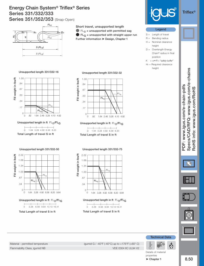
Energy Chain System® Triflex® SeriesSeries 331/332/333Series 351/352/353 (Snap-Open)
Energy Chain System® Triflex® SeriesSeries 331/332/333Series 351/352/353 (Snap-Open)
®Triflex®
Legend
PD
F:
ww
w.ig
us.
com
/e-c
hai
n-p
dfs
Sp
ecs/
CA
D/R
FQ
: w
ww
.igu
s.co
m/e
-ch
ain
sR
oH
S in
fo:
ww
w.ig
us.
com
/Ro
HS
8.50
Details of materialproperties
‰ Chapter 1
S = Length of travel
R = Bending radius
H = Nominal clearance
height
D = Overlength Energy
Chain® radius in final
position
K = π • R + “safety buffer”
HF = Required clearance
height
F °
Technical Data
Material - permitted temperature igumid G / -40°F (-40°C) up to +176°F (+80° C)
Flammability Class, igumid NB VDE 0304 IIC UL94 V2
FLG
FLB
H
HF
S (FLG)
S (FLB)
Short travel, unsupported lengthl FLB = unsupported with permitted sag
l FLG = unsupported with straight upper run
Further information ‰ Design, Chapter 1
.17
00
FLB
0 1.64 3.28 6.564.92 8.20
.34
.50
.84
1.00
.67
FLG
.82 1.64 3.282.46 4.10 4.92
Fill
wei
ght
in lb
s/ft
Unsupported length in ft FLB/FLG
Total Length of travel S in ft
Unsupported length 331/332-16 Unsupported length 331/332-32
.17
00
FLB
0 1.64 3.28 6.564.92 8.20
.34
.50
.84
1.00
.67
FLG
.82 1.64 3.282.46 4.10 4.92
Fill
wei
ght
in lb
s/ft
Unsupported length in ft FLB/FLG
Total Length of travel S in ft
Unsupported length 331/332-50
.34
00 1.64 3.28 6.564.92 8.20
FLB
0 3.28 6.56 13.139.84 16.41
.67
1.00
1.68
9.84
2.02
1.34
FLG
Fill
wei
ght
in lb
s/ft
Unsupported length in ft FLB/FLG
Total Length of travel S in ft
Unsupported length 331/332-75
.34
00
FLB
0 3.28 6.56 13.139.84 16.41
.67
1.00
1.68
2.02
1.34
FLG
1.64 3.28 6.564.92 8.20 9.84
Fill
wei
ght
in lb
s/ft
Unsupported length in ft FLB/FLG
Total Length of travel S in ft

®331351
8.51
Inte
rnet
: h
ttp
://w
ww
.igu
s.co
mem
ail:
sale
s@ig
us.
com
Qu
ickS
pec
/RF
Q:
htt
p:/
/ww
w.ig
us.
com
/qu
icks
pec
Tele
ph
on
e1-
800-
521-
2747
Fax
1-
401-
438-
7270
igu
s®E
ner
gy
Ch
ain
Sys
tem
®
Energy Chain System® Triflex® SeriesSingle Axis Movement
Single Axis Movement, Series 331/351B
a Bi
331-16 max. .55” (14 mm)
331/351-50 max. 1.77” (45 mm)331-75 max. 2.64” (67 mm)
331-32 max. 1.10” (28 mm)
Part No. Bi Ba Weight
in. (mm) in. (mm) lbs/ft (kg/m)
331-16- .63 (16) 1.02 (26) ≈ 0.22 (.33)
331-32- 1.26 (32) 1.97 (50) ≈ 0.60 (.90)
331-50- 1.97 (50) 2.68 (68) ≈ 0.94 (1.40)
331-75- 2.95 (75) 3.78 (96) ≈ 1.58 (2.35)
Snap-open
351-50- 1.97 (50) 2.68 (68) ≈ 0.94 (1.40)
Supplement part number with required radius from below.for example 331-50-100-0
Pitch = .98 (25 mm)Links/ft (m) = 12.19 (40)Dimensions E = .79 (20 mm)Ba = 1.97 (50 mm)
S/2
T E
DS
H
H -
R
Ba
Ba
For center mount applications:
Tube length = s/2 + K
Pitch = .52 (13.3 mm)Links/ft (m) = 23.17 (76)Dimensions E = .39 (10 mm)Ba = 1.02 (26 mm)
R 2.95 (075) 3.94 (100) 4.92 (125) 5.91 (150) 7.87 (200) 9.84 (250)
H 7.87 (200) 9.84 (250) 11.81 (300) 13.78 (350) 17.72 (450) 21.65 (550)
D 5.12 (130) 6.10 (155) 7.09 (180) 8.07 (205) 10.04 (255) 12.01 (305)
K 12.01 (305) 15.15 (385) 18.30 (465) 21.46 (545) 27.56 (700) 34.06 (865)
R 1.50 (038) 1.89 (048) 2.95 (075) 3.94 (100)
H 4.13 (105) 4.92 (125) 7.09 (180) 9.06 (230)
D 2.76 (70) 3.15 (80) 4.13 (105) 5.12 (130)
K 7.87 (200) 9.06 (230) 12.40 (315) 15.75 (400)
Pitch = 1.18 (30 mm)Links/ft (m) = 10.36 (34)Dimensions E = .98 (25 mm)Ba = 2.68 (68 mm)
R 3.94 (100) 4.92 (125) 5.91 (150) 7.87 (200) 9.84 (250)
H 10.63 (270) 12.60 (320) 14.76 (375) 18.50 (470) 22.44 (570)
D 7.68 (195) 8.66 (220) 9.65 (245) 11.61 (295) 13.58 (345)
K 17.13 (435) 20.47 (520) 23.23 (590) 29.53 (750) 35.83 (910)
Installation dimensions for single-axis movement
Series 331-16
Series 331-32
Series 331-50
Pitch = 1.42 (36 mm)Links/ft (m) = 8.53 (28)Dimensions E = .98 (25 mm)Ba = 3.78 (96 mm)
R 5.51 (140) 6.89 (175) 7.87 (200) 9.84 (250) 11.81 (300)
H 14.96 (380) 17.71 (450) 19.69 (500) 23.62 (600) 27.56 (700)
D 9.45 (240) 10.83 (275) 11.81 (300) 13.78 (350) 15.75 (400)
K 21.65 (550) 25.98 (660) 29.13 (740) 35.43 (900) 41.73 (1060)
Series 331-75
Pitch = 1.18 (30 mm)Links/ft (m) = 10.36 (34)Dimensions E = .98 (25 mm)Ba = 2.68 (68 mm)
R 3.94 (100) 4.92 (125) 5.91 (150) 7.87 (200) 9.84 (250)
H 10.63 (270) 12.60 (320) 14.76 (375) 18.50 (470) 22.44 (570)
D 7.68 (195) 8.66 (220) 9.65 (245) 11.61 (295) 13.58 (345)
K 17.13 (435) 20.47 (520) 23.23 (590) 29.53 (750) 35.83 (910)
Series 351-50 (Snap-Open)
332- 50- 0100-
Width
Part No. structure
Colorblack
Bendingradius
series

332352
®
8.52
PD
F:
ww
w.ig
us.
com
/e-c
hai
n-p
dfs
Sp
ecs/
CA
D/R
FQ
: w
ww
.igu
s.co
m/e
-ch
ain
sR
oH
S in
fo:
ww
w.ig
us.
com
/Ro
HS
Energy Chain System® Triflex® SeriesDouble Axis Movement
Double Axis Movement, Series 332/352
Ba Bi
332-16 max. .55” (14 mm)
332/352-50 max. 1.77” (45 mm)332-75 max. 2.64” (67 mm)
332-32 max. 1.10” (28 mm)
Supplement part number with required radius from belowfor example, 332-75-2-200-0
Part No. Bi Ba Weightin. (mm) in. (mm) lbs/ft (kg/m)
332-16- .63 (16) 1.02 (26) ≈ 0.22 (.33)
332-32- 1.26 (32) 1.97 (50) ≈ 0.60 (.90)
332-50- 1.97 (50) 2.68 (68) ≈ 0.94 (1.40)
332-75- 2.95 (75) 3.78 (96) ≈ 1.58 (2.35)
Snap-open
352-50- 1.97 (50) 2.68 (68) ≈ 0.94 (1.40)
Pitch = .98 (25 mm)Links/ft (m) = 12.19 (40)Dimensions E = .79 (20 mm)Ba = 1.97 (50 mm)
S/2
T E
DS
H
H -
R
Ba
Ba
For center mount applications:
Tube length = s/2 + K
Pitch = .52 (13.3 mm)Links/ft (m) = 23.17 (76)Dimensions E = .39 (10 mm)Ba = 1.02 (26 mm)
R 2.95 (075) 3.94 (100) 4.92 (125) 5.91 (150) 7.87 (200) 9.84 (250)
H 7.87 (200) 9.84 (250) 11.81 (300) 13.78 (350) 17.72 (450) 21.65 (550)
D 5.12 (130) 6.10 (155) 7.09 (180) 8.07 (205) 10.04 (255) 12.01 (305)
K 12.01 (305) 15.15 (385) 18.30 (465) 21.46 (545) 27.56 (700) 34.06 (865)
R 1.50 (038) 1.89 (048) 2.95 (075) 3.94 (100)
H 4.13 (105) 4.92 (125) 7.09 (180) 9.06 (230)
D 2.76 (70) 3.15 (80) 4.13 (105) 5.12 (130)
K 7.87 (200) 9.06 (230) 12.40 (315) 15.75 (400)
Pitch = 1.18 (30 mm)Links/ft (m) = 10.36 (34)Dimensions E = .98 (25 mm)Ba = 2.68 (68 mm)
R 3.94 (100) 4.92 (125) 5.91 (150) 7.87 (200) 9.84 (250)
H 10.63 (270) 12.60 (320) 14.76 (375) 18.50 (470) 22.44 (570)
D 7.68 (195) 8.66 (220) 9.65 (245) 11.61 (295) 13.58 (345)
K 17.13 (435) 20.47 (520) 23.23 (590) 29.53 (750) 35.83 (910)
Installation dimensions for double-axis movement
Series 332-16
Series 332-32
Series 332-50
Pitch = 1.42 (36 mm)Links/ft (m) = 8.53 (28)Dimensions E = .98 (25 mm)Ba = 3.78 (96 mm)
R 5.51 (140) 6.89 (175) 7.87 (200) 9.84 (250) 11.81 (300)
H 14.96 (380) 17.71 (450) 19.69 (500) 23.62 (600) 27.56 (700)
D 9.45 (240) 10.83 (275) 11.81 (300) 13.78 (350) 15.75 (400)
K 21.65 (550) 25.98 (660) 29.13 (740) 35.43 (900) 41.73 (1060)
Series 332-75
Pitch = 1.18 (30 mm)Links/ft (m) = 10.36 (34)Dimensions E = .98 (25 mm)Ba = 2.68 (68 mm)
R 3.94 (100) 4.92 (125) 5.91 (150) 7.87 (200) 9.84 (250)
H 14.96 (380) 12.60 (320) 14.76 (375) 18.50 (470) 22.44 (570)
D 9.45 (240) 8.66 (220) 9.65 (245) 11.61 (295) 13.58 (345)
K 21.65 (550) 20.47 (520) 23.23 (590) 29.53 (750) 35.83 (910)
Series 352-50 (Snap-Open)
332- 50- 0200-200/
RBR
Bendingradius
Part No. structure
Colorblack
Bendingradius
Width
Series

®333353
8.53
Inte
rnet
: h
ttp
://w
ww
.igu
s.co
mem
ail:
sale
s@ig
us.
com
Qu
ickS
pec
/RF
Q:
htt
p:/
/ww
w.ig
us.
com
/qu
icks
pec
Tele
ph
on
e1-
800-
521-
2747
Fax
1-
401-
438-
7270
igu
s®E
ner
gy
Ch
ain
Sys
tem
®
Energy Chain System® Triflex® SeriesTriple Axis Movement
Triple Axis Movement, Series 333/353 (Snap-Open)B
a Bi
333-16 max. .55” (14 mm)
333/353-50 max. 1.77” (45 mm)333-75 max. 2.64” (67 mm)
333-32 max. 1.10” (28 mm)
Supplement part number with required radius from abovefor example, 333-32-100-0
Part No. Bi Ba Weightin. (mm) in. (mm) lbs/ft (kg/m)
333-16- .63 (16) 1.02 (26) ≈ 0.22 (.33)
333-32- 1.26 (32) 1.97 (50) ≈ 0.60 (.90)
333-50- 1.97 (50) 2.68 (68) ≈ 0.94 (1.40)
333-75- 2.95 (75) 3.78 (96) ≈ 1.58 (2.35)
Snap-open
353-50- 1.97 (50) 2.68 (68) ≈ 0.94 (1.40)
Pitch = .98 (25 mm)Links/ft (m) = 12.19 (40)Dimensions E = .79 (20 mm)Ba = 1.97 (50 mm)
T E
D S/2
S
H
H -
Ba
Ba
R*
For center mount applications:
Tube length = s/2 + K
Pitch = .52 (13.3 mm)Links/ft (m) = 23.08 (76)Dimensions E = .39 (10 mm)Ba = 1.02 (26 mm)
R (076) 3.78 (096) 5.91 (150) 7.87 (200)
H 7.09 (180) 8.66 (220) 12.99 (330) 16.93 (430)
D 4.13 (105) 4.92 (125) 7.09 (180) 9.06 (230)
K 12.60 (320) 14.96 (380) 21.65 (550) 27.95 (710)
Pitch = 1.18 (30 mm)Links/ft (m) = 10.16 (34)Dimensions E = .98 (25 mm)Ba = 2.68 (68 mm)
R 7.87 (200) 9.84 (250) 11.81 (300) 15.75 (400) 19.69 (500)
H 18.50 (470) 22.44 (570) 26.38 (670) 34.25 (870) 42.13 (1070)
D 11.61 (295) 13.58 (345) 15.55 (395) 19.49 (495) 23.43 (595)
K 29.53 (750) 35.83 (910) 42.13 (1070) 54.33 (1380) 66.54 (1690)
Installation dimensions for triple-axis movement
Series 333-16
Series 333-32
Series 333-50
Pitch = 1.42 (36 mm)Links/ft (m) = 8.47 (28)Dimensions E = .98 (25 mm)Ba = 3.78 (96 mm)
Series 333-75
R 5.91 (150) 7.87 (200) 9.84 (250) 11.81 (300) 15.75 (400) 19.69 (500)
H 13.78 (350) 17.72 (450) 21.65 (550) 25.59 (650) 33.46 (850) 41.33 (1050)
D 8.07 (205) 10.04 (255) 12.01 (305) 13.98 (355) 17.91 (455) 21.85 (555)
K 21.46 (545) 27.56 (700) 33.86 (860) 40.16 (1020) 51.18 (1300) 63.19 (1605)
R 11.02 (280) 13.78 (350) 15.75 (400) 19.69 (500) 23.62 (600)
H 25.98 (660) 31.50 (800) 35.43 (900) 43.31 (1100) 51.18 (1300)
D 14.96 (380) 17.72 (450) 19.69 (500) 23.62 (600) 27.56 (700)
K 38.98 (990) 47.64 (1210) 55.12 (1400) 66.93 (1700) 78.74 (2000)
Pitch = 1.18 (30 mm)Links/ft (m) = 10.16 (34)Dimensions E = .98 (25 mm)Ba = 2.68 (68 mm)
Series 353-50 (Snap-Open)
R 7.87 (200) 9.84 (250) 11.81 (300) 15.75 (400) 19.69 (500)
H 18.50 (470) 22.44 (570) 26.38 (670) 34.25 (870) 42.13 (1070)
D 11.61 (295) 13.58 (345) 15.55 (395) 19.49 (495) 23.43 (595)
K 29.53 (750) 35.83 (910) 42.13 (1070) 54.33 (1380) 66.54 (1690)
* The bending radii are doubledin the case of the Series 333Energy Chain®
333- 50- 0100-
Part No. structure
ColorblackBendingradius
Width
Series
RBR

Triflex®
®
8.54
PD
F:
ww
w.ig
us.
com
/e-c
hai
n-p
dfs
Sp
ecs/
CA
D/R
FQ
: w
ww
.igu
s.co
m/e
-ch
ain
sR
oH
S in
fo:
ww
w.ig
us.
com
/Ro
HS
Energy Chain System® Triflex® SeriesInterior Separation
Interior SeparationModular separators are available as interior shelving for the igus® Triflex® System. They can be used for both vertical and horizon-tal sub-division. If the separators are assembled every other link and turned 90°, the tube can be sub-divided into four segments.We recommend ordering the tube pre-assembled, as subsequent assembly of separators is only possible after dismantling the tube.Please note that assembled separators have a different part number than unassembled separators.
Horizontal sub-division
331/332/333-75
331/332/333-50351/352/353-50
331/332/333-32
Vertical sub-division
333, 351, 376
333, 351, 376
1.45
(36.
8)
1.26
(32)
.08 (2)
.31(8)
.08 (2)
.31(8)
2.11
(53.
6)
1.97
(50)
3.10
(78.
8)
2.95
(75)
.71(18)
.12 (3)Separator
Unassembled Part No. 375
Assembled Part No. 376
Separator
Unassembled Part No. 350
Assembled Part No. 351
Separator
Unassembled Part No. 332
Assembled Part No. 333

®Triflex®
8.55
Inte
rnet
: h
ttp
://w
ww
.igu
s.co
mem
ail:
sale
s@ig
us.
com
Qu
ickS
pec
/RF
Q:
htt
p:/
/ww
w.ig
us.
com
/qu
icks
pec
Tele
ph
on
e1-
800-
521-
2747
Fax
1-
401-
438-
7270
igu
s®E
ner
gy
Ch
ain
Sys
tem
®
Energy Chain System® Triflex® SeriesMounting Brackets
CB
E
D A
C
B
.39
(10)
A
.31
(8)
D
K
E
333...1PZ(B) 333...2PZ(B)
For high loads we recommend screwing themounting brackets to the chain. If you haveany questions, please give us a call.
Series Part No. Part No. A B C D E K NFull Set with Full Set withouttiewrap plate tiewrap plate in. (mm) in. (mm) in. (mm) in. (mm) in. (mm) in. (mm) No. of Teeth
331/332/333-32 333-32-12PZB 333-32-12-PZ 2.60 (66) .59 (15) 1.81 (46) 3.23 (82) .26 (6.5) .59 (15) 3
331/332/333-50 333-50-12PZB 333-50-12-PZ 3.31 (84) .59 (15) 1.97 (50) 3.94 (100) .26 (6.5) .59 (15) 5
331/332/333-75 333-75-12PZB 333-75-12-PZ 4.29 (109) .59 (15) 2.17 (55) 4.92 (125) .26 (6.5) .59 (15) 7
Snap-open series
351/352/353-50 333-50-12PZB 333-50-12-PZ 3.31 (84) .59 (15) 1.97 (50) 3.94 (100) .26 (6.5) .59 (15) 5
333-32- 12- PZB
Part No. structure
Mounting brackets forselected chain type
With assembled strainrelief tiewrap plates
Full set = 12
Full set, for both ends:
+tiewrap plate
Single-part order:
+tiewrap plate
Mounting bracket with bore
+tiewrap plate
Mounting bracket with pin
PZB
PZB
333- 32- 12
333- 32- 1 PZB
333- 32- 2
Part No. Width Number For Series
Tiewrap plate in. (mm) of teeth
333-32-ZB 1.57 (40) 3 331/332/333-32
333-50-ZB 2.28 (58) 5 331/332/333-50 351/352/353-50
333-75-ZB 3.27 (83) 7 331/332/333-75
Tiewrap plate as individual part
Special tiewrap plates for Triflex® Energy Chains®
l Single-piece for installation inside switch cabinets or machine assembly
l Accessory for igus® Energy Chain Systems®
l Easy to assemble, no need for screws
Possible installationconfigurations -
Option 1: KMA
• Corrosion resistant• Strain relief with tiewrap
plate
19°19°
333-50-1PZMoving end
333-50-2PZBFixed end
(with tiewrap plate 333-50-ZB)
Standard

Triflex®
®
8.56
PD
F:
ww
w.ig
us.
com
/e-c
hai
n-p
dfs
Sp
ecs/
CA
D/R
FQ
: w
ww
.igu
s.co
m/e
-ch
ain
sR
oH
S in
fo:
ww
w.ig
us.
com
/Ro
HS
Energy Chain System® Triflex® SeriesMounting Brackets
Series Part No. A M C L T E F G
331/332/333-16 330-16-12 1.38 (35) 2.09 (53) .83 (21) 2.24 (57) .04 (1) .39 (10) .18 (4.5) .24 (6)
331/332/333-32 330-32-12 2.60 (66) 3.31 (84) 1.73 (44) 3.46 (88) .08 (2) .79 (20) .28 (7) .35 (9)
331/332/333-50 330-50-12 3.31 (84) 4.02 (102) 2.44 (62) 4.17 (106) .08 (2) .98 (25) .28 (7) .35 (9)
331/332/333-75 330-75-12 4.29 (109) 5.00 (127) 3.54 (90) 5.16(131) .08 (2) .98 (25) .28 (7) .35 (9)
E
T
E
A
F
LM
C
G330-26-2 / 330-75-2 330-16-1 / 330-75-1
DB E
I A
J
A H
F
G
C
338-16-2 / 338-75-2 338-16-1 / 338-75-1
Series Part No. A B C D E F G H I J
331/332/333-16 338-16-12 .47 (12) .12 (3) .98 (25) .20 (5) .39 (10) .43 (11) .18 (4,5) .98 (25) .91 (23) .24 (6)
331/332/333-32 338-32-12 .94 (24) .22 (5.5) 1.85 (47) .31 (8) .94 (24) .79 (20) .28 (7) 1.93 (49) 1.77 (45) .43 (11)
331/332/333-50 338-50-12 1.65 (42) .22 (5.5) 3.03 (77) .47 (12) 1.38 (35) .94 (24) .35 (9) 2.64 (67) 2.44 (62) .59 (15)
331/332/333-75 338-75-12 2.56 (65) .22 (5.5) 3.03 (77) .47 (12) 1.38 (35) .94 (24) .35 (9) 3.74 (95) 3.54 (90) .59 (15)
Snap-open
351/352/353-50 338-50-12 1.65 (42) .22 (5.5) 3.03 (77) .47 (12) 1.38 (35) .94 (24) .35 (9) 2.64 (67) 2.44 (62) .59 (15)
330- 32- 12
Part No. structure
Mounting bracketsfor selected chaintype
Full set = 12
Width
Full set, 4 parts
2 with pin / 2 with bore:
Single-part order:
Mounting bracket with bore
Mounting bracket with pin
330- 32- 12
330- 32- 1
330- 32- 2
338- 32- 12
Part No. structure
Mounting bracketsfor selected chaintype
Full set = 12
Width
Full set, 4 parts
2 with pin / 2 with bore:
Single-part order:
Mounting bracket with bore
Mounting bracket with pin
338- 32- 12
338- 32- 1
338- 32- 2
Possible installationconfigurations -
Option 2: pivotingsteel flange
• Galvanized steel• Electrically conductive• Flush mounting
30°30°
10°10°
330-16-1 / 330-75-1Moving end
330-16-2 / 330-75-2Fixed end
Option 3: angle
• Galvanized steel• Electrically conductive• Can be attached to top or
bottom of the machine
90°
70°
5°
338-16-1 / 338-75-1Moving end
338-16-2 / 338-75-2Fixed end
Possible installationconfigurations -


![Download [2.95 MB]](https://img.pdfslide.net/doc/110x75/587752971a28ab206f8bba51/download-295-mb.jpg)