Embed Size (px)
Citation preview

1
Energy Harvesting by means of Flow-Induced Vibrations on
Aerospace Vehicles
Daochun Li1, Yining Wu1, Andrea Da Ronch2*, Jinwu Xiang1†
1School of Aeronautic Science and Engineering, Beihang University, Beijing, China
2Engineering and the Environment, University of Southampton, Southampton, UK
Abstract
This paper reviews the design, implementation, and demonstration of energy
harvesting devices that exploit flow-induced vibrations as the main source of energy.
Starting with a presentation of various concepts of energy harvesters that are designed
to benefit from a general class of flow-induced vibrations, specific attention is then
given at those technologies that may offer, today or in the near future, a potential
benefit to extend the operational capabilities and to monitor critical parameters of
unmanned aerial vehicles. Various phenomena characterized by flow-induced
vibrations are discussed, including limit cycle oscillations of plates and wing sections,
vortex-induced and galloping oscillations of bluff bodies, vortex-induced vibrations of
downstream structures, and atmospheric turbulence and gusts. It was found that linear
* First Corresponding Author. Email: [email protected]; Tel: +44(0)23-8059-4787; Postal Address:
Building 13 (Tizard), room 5043, University of Southampton, Southampton, SO17 1BJ, UK.
† Second Corresponding Author. Email: [email protected]; Tel: +86(0)10-8233-8786; Postal Address: New
Main Building, room D503, Beihang University, Beijing, 100083, China

2
or linearized modelling approaches are commonly employed to support the design
phase of energy harvesters. As a result, highly nonlinear and coupled phenomena that
characterize flow-induced vibrations are neglected in the design process. The Authors
encourage a shift in the current design paradigm: considering coupled nonlinear
phenomena, and adequate modelling tools to support their analysis, from a design
limitation to a design opportunity. Special emphasis is placed on identifying designs
and implementations applicable to aircraft configurations. Application fields of flow-
induced vibrations-based energy harvesters are discussed including power supply for
wireless sensor networks and simultaneous energy harvest and control. A large body
of work on energy harvesters is included in this review journal. Whereas most of the
references claim direct applications to unmanned aerial vehicles, it is apparent that, in
most of the cases presented, the working principles and characteristics of the energy
harvesters are incompatible with any aerospace applications. Finally, the challenges
that hold back the integration of energy harvesting technologies in the aerospace field
are discussed.
Keywords: flow-induced vibration; energy harvesting; piezoelectric; limit cycle
oscillation; vortex-induced vibration; galloping

3
Table of contents
Abstract .......................................................................................................................... 1
1. Introduction .......................................................................................................... 12
2. Flow-induced vibrations ...................................................................................... 17
2.1 Limit cycle oscillations of plates ................................................................... 18
2.2 Galloping and vortex-induced vibrations of bluff bodies .............................. 19
2.3 Limit cycle oscillations of wing sections ....................................................... 21
2.4 Vortex-induced vibrations generated in wake vortices .................................. 23
2.5 Turbulence and other variable flow-based vibrations .................................... 24
3 Modelling and experiments .................................................................................. 25
3.1 Modelling approaches .................................................................................... 26
3.1.1 Aerodynamics ......................................................................................... 26
3.1.2 Transduction mechanism ........................................................................ 34
3.1.3 Systems used for energy harvesting ........................................................ 37
3.2 Experimental investigations ........................................................................... 44
3.2.1 Wind tunnel experiment .............................................................................. 45
3.2.2 Water tunnel experiment ............................................................................. 50
3.3 Indicators of harvested energy ....................................................................... 52
4 Energy harvesting designs and implementations ................................................. 54

4
4.1 Limit cycle oscillations of plates ................................................................... 54
4.2 Galloping and vortex-induced vibrations of bluff bodies .............................. 56
4.3 Limit cycle oscillations of wing sections ....................................................... 61
4.4 Vortex-induced vibrations generated in wake vortices .................................. 64
4.5 Turbulence and other variable flow-based vibrations .................................... 67
4.6 In-aircraft energy harvesting implementations .............................................. 68
5 Applications of energy harvesting ....................................................................... 72
5.1 Power supply for wireless sensor networks ................................................... 72
5.2 Simultaneous energy harvest and control ...................................................... 76
6 Summary and Challenges .................................................................................... 80
6.1 Modelling of nonlinear coupled aero-electro-elastic model .......................... 81
6.2 Experimental testing ...................................................................................... 82
6.3 Enhancing harvested energy and performance .............................................. 83
6.4 Scaling effects on the energy harvesting performance .................................. 83
6.5 Design and power management of host systems ........................................... 84
6.6 Balance between advantages and disadvantages of energy harvesting .......... 84
Acknowledgement ....................................................................................................... 86
References .................................................................................................................... 86
Figure Captions .......................................................................................................... 112

5
Tables ......................................................................................................................... 118

6
Nomenclature
Symbols
a1, a3 coefficients to calculate the fluid force on bluff bodies
a dimensionless location of the elastic axis
A1, A2 coefficients of Wagner function
Af frontal area of the harvester in operation
b characteristic length
B flux density at each coil segment
Bl electromagnetic coupling coefficient
Bl electromagnetic coupling matrix
b1, b2 coefficients of Wagner function
c damping coefficient
cl sectional lift coefficient
cd sectional drag coefficient
cm sectional moment coefficient
cs nonlinear parameter due to stall
c elastic stiffness matrix of piezoelectric materials
CP capacitance of the piezoelectric materials
Cp equivalent piezoelectric capacitance matrix
C damping matrix
dlcoil vector of each segment of the coil
D aerodynamic drag

7
D electric displacement vector
e total flow energy
e piezoelectric stress matrix
E harvested energy
E0 total energy
E electric field vector
f external force vector
Fema electromagnetic force
Femo electromotive force
F vector of generalized aerodynamics
GIt torsional stiffness per length
h plunge displacement
i induced current in the coil
I induced electric current flowing
Iα moment of inertia per length
I vector of induced electric current flowing
k stiffness
K stiffness matrix
l span length
L aerodynamic lift
Lc internal coil inductance
Lc inherent coil inductance matrix

8
m mass per length
mT total mass
M aerodynamic moment
Mb bending moment along the length
Mp bending moment generated due to the transducers
M mass matrix
O zero vector
p flow pressure
P power output
P0 power that the structure received form the flow
Pf bulk mechanical power available in flow
q thermal flux vector
r1z, r2z, r3z coefficients of ONERA model
R applied load resistance
Rc internal resistance of the inductor coil
sz1, sz2, sz3 coefficients of ONERA model
S characteristic area
S strain vector of piezoelectric materials
T stress vector of piezoelectric materials
u modal time coordinate
U flow velocity
U global vector of coordinate

9
v flow velocity vector
V generated voltage
V piezoelectric voltage output vector
xα dimensionless eccentricity
YI bending stiffness per length
α pitch displacement
αeff effective angle of attack
δ semi-free-play
ε ratio of the stiffness coefficients
ε matrix of permittivity components
modal function
λ1, λ2 coefficients of ONERA model
μ energy conversion efficiency
ρ air density
Θ electromechanical coupling coefficient
Θ piezoelectric coefficient matrix
τ stress tensor
τv viscous stress tensor
Superscripts
b bending motions
E measured at a constant electric field
i in the inductive EH circuit

10
S measured at a constant strain
t torsional motions
T transposition
. differential with respect to the time
‘ differential with respect to the length
Subscripts
av average value
h plunge displacement
i orders of bending modes
j orders of torsional modes
α pitch displacement
Acronyms
CFD Computational fluid dynamics
DAQ data acquisition
DOF degree of freedom
DNS Direct Numerical Simulation
EH energy harvesting
FEM finite element method
FIV flow-induced vibration
HALE high-altitude long-endurance
HAWT horizontal axis wind turbine
HB harmonic balance

11
IB immersed boundary
IPMC ionic polymer metal composites
LB Lattice Boltzmann
LFD linear frequency domain
LCO limit cycle oscillation
LDV laser Doppler velocimetry
MAV micro aerial vehicle
MPPT maximum power point tracker
NI National Instruments
ODE ordinary differential equation
PIV particle image velocimetry
RANS Reynolds-averaged Navier-Stokes
RMS root mean square
ROM reduced order model
UAV unmanned aerial vehicle
UVLM unsteady vortex-lattice methods
VAACT vertical axis autorotation current turbine
VIV vortex-induced vibration
VIVACE vortex-induced vibration aquatic clean energy
WSN wireless sensor network

12
1. Introduction
One of the greatest challenges in aerospace engineering is the limited energy
available during flight. This problem affects aircraft endurance and operational flight
missions. Of particular interest are unmanned aerial vehicles (UAVs) and micro aerial
vehicles (MAVs) which are designed to conduct intelligence, surveillance, and
reconnaissance missions [1]. The availability of more energy could contribute to higher
performance and extended mission profiles.
Generally, batteries are used as storage of electricity, offer a high energy density at
low cost, have a low self-discharge, and provide potentially long lifetime cycles.
However, there are critical aspects related with the use of batteries which hold back
their use [2]. The first practical and economical penalty is the need to replace the
batteries when they achieve the end of the operating life. Thereby, they are likely to be
deployed in large numbers in remote areas. A second problem is linked to safety,
because modern batteries may suffer from thermal runaway, ignite, and explode due to
short-circuit, extreme temperatures, or inappropriate charge or discharge, not to forget
poor design.
A potential technology that may replace batteries in the near future is energy
harvesting (EH). EH takes advantage of ambient energy sources to generate usable
electric energy based on various transduction approaches. The harvested energy, through

13
appropriate transducers specific to each application, can be stored and used to recharge
on-board batteries and to operate low power consumption devices, making these self-
sufficient in energy supply. Various potential energy sources for EH are shown in Fig. 1
[3]. Benefits of EH are that: a) there is no need to replace batteries; b) there is no need
of cabling; c) they are easy to retrofit infrastructures; and d) they represent a “truly fit-
and-forget” approach that allows reducing physical installation, replacement and
maintenance costs, and time [4]. For these properties, EH are commonly used for
systems that are designed to operate in remote areas with limited power supply and
maintenance, and the requirement of long service time, such as electronic sensors used
for structural health monitoring. Of specific interest herein is the application of EH in
aerospace problems, generally targeting UAVs. With EH technology, future UAVs may
achieve better performance: enhanced cruise range and duration time, better
maintainability and viability, and larger mission payload.
Potential energy sources for aerospace applications include wind, solar radiation,
and mechanical vibration, see Fig. 1. Among these EH approaches, the study on aircraft
solar EH is quite mature. Table 1 summarises the power density of different EH
methods [5], and it is found that solar EH through photo-voltaic conversion provides
high power output density. Solar cells have been practically implemented in high-
altitude long-endurance (HALE) aircraft, and being currently demonstrated on the Solar

14
Impulse3 set to travel around the world using solar energy. Developing a solar EH
system to harvest sufficient energy for a sustained flight throughout the day and night is
still a challenging task. This becomes more critical for smaller scale aircraft because of
the lower aerodynamic performance compared to HALE configurations. Furthermore,
the design of a solar EH module involves complicated trade-offs, and the expense of
solar EH systems is still relatively large. Therefore, it is worthwhile to explore EH from
other applicable energy sources such as piezoelectric or vibrational EH.
Turbines using one or more flapping foils can be used as an alternative to rotary
wind turbines and river, oceanic and tidal current water turbines, although industrial
development is at very early stages. Such flapping foil turbines have some key potential
advantages, including lower foil velocities (and hence lower noise and wildlife impact),
and more effective small-scale and shallow water operation. Reference [6] presented an
extensive review on the progress in flapping foil power generation in the last few
decades. The effects of a number of parameters were investigated, including foil
kinematics (modes, frequencies, amplitudes and time histories of motion), foil and
system geometry (shape, configuration and structural flexibility), and flow physics
effects (Reynolds number and turbulence, shear flows and ground effect).
Flow-induced vibrations (FIVs) are generally considered as negative phenomena
since in many cases these unwanted vibrations may cause a reduction of the life span
3 The Solar Impulse project: http://www.solarimpulse.com/

15
and structural damage. For example, in the aerospace field, aeroelastic vibrations can
jeopardize the aircraft structural integrity (e.g. flutter, limit cycle oscillations, and
dynamic response to atmospheric turbulence) and their performance (e.g. decreased
control effectiveness and manoeuvrability, increased drag) [7-12]. A large body of work
on flutter control of aeroelastic systems is available [13-19]. With structural and
aerodynamic nonlinearities, aeroelastic systems may exhibit a variety of stable and
unstable vibrations (e.g. chaotic motions), and efforts have been made to reduce and
suppress aeroelastic vibrations. Limit cycle oscillations (LCOs) limit the amplitude of
the structure into a certain range and hence avoid the structure from being destroyed by
aeroelastic instability, but LCOs affect the performance of the structure and contribute
to structural fatigue damage.
Flow-induced vibrations are now considered as one of the most promising potential
sources of energy. The main reason is that these vibrations can be obtained from the
fluid-structure interaction by utilizing energy harvesters in various natural flow
conditions. In addition, fluid-induced vibrations present advantages compared to normal
vibrations. For example, vibrations due to the instability phenomenon of the structures
in the flow are self-excited, which makes the corresponding energy harvesters more
feasible and scalable. So far, a large body of work on EH based on flow-induced
vibrations is available in the open literature. Reference [20] reviewed piezoelectric wind
EH designs based on galloping and vortex-induced vibrations (VIVs) of bluff bodies

16
and LCOs of wing sections. The potential of active EH was emphasised, adapting the
EH system to changes in the surrounding environment to maintain optimal performance
and the highest outputs. Since 2013, a growing number of studies on EH from bluff
bodies and wing sections has been reported. Apart from these EH designs based on the
galloping, VIVs or aerofoil-based vibrations, there are still a large number of potential
flow-induced vibration-based designs such as using the LCOs of cantilevered plates or
wake galloping phenomena, which were not included in Ref. [20]. Despite the initial
intentions, most studies fail to investigate EH devices for realistic aerospace
applications. From the open literature, it is apparent that a feasibility study of EH
technology, whereby the performance of a flying prototype equipped with an EH device
is compared with the baseline configuration (without EH), has never been reported to
date. This is surprising given the ever increasing popularity of EH in the aerospace and
related disciplines.
The current review paper aims at filling that gap in documenting the methods,
applications, and challenges of EH from flow-induced vibrations based on the latest
open literatures. The objectives are to: (1) review flow-induced vibrations that have
been exploited for specific EH designs, and determine key aspects which benefit EH
applications; (2) overview EH designs based on different types of flow-induced
vibrations including LCOs of plates and wing sections, galloping and VIVs of bluff
bodies, VIVs of downstream structures and variable flow or turbulence-based

17
vibrations, and illustrate the key factors of parameters of each EH design to improve EH
performance; and (3) review current EH applications and address the potential
applications of flow-induced vibration-based EH in the aerospace field, particularly EH
for UAVs.
Different types of flow-induced vibrations being exploited for EH are summarized
in Section 2. Section 3 provides the fundamental modelling and experimental
approaches of flow-induced vibration-based EH systems. In Section 4, various EH
concepts and implementations are reviewed. The EH applications are introduced in
Section 5, and the potential methods for aerospace applications are also identified.
Finally, the challenges and future applications of flow-induced vibration-based EH are
discussed in Section 6.
2. Flow-induced vibrations
This Section introduces several flow-induced vibrations which have been exploited
for specific EH designs and applications. Based on different structures and vibrational
mechanisms, flow-induced vibrations are overviewed including self-excited oscillations
of plates, bluff bodies, and wing sections in steady flow, vibrations due to wake vortices
or turbulence. The corresponding features of each flow-induced vibration are discussed
from a quantitative point of view. Starting from a general treatment of the problem as
experienced in several engineering fields, the most relevant phenomena in the aerospace
field are discussed to provide background information for the remainder of the paper.

18
2.1 Limit cycle oscillations of plates
Generally, for vibrations in steady flow, the mutual interaction between fluid and
structure is the most commonly observed scenario where structures become unstable as
the flow velocity exceeds a critical value and undergo self-excited oscillations. A typical
example of flow-induced instability is the flutter of a flexible plate that is fixed at the
leading edge and free at the trailing edge in an axial flow, see Fig. 2. This configuration
has been extensively investigated for its rich and complex dynamics [21-25]. Plates of
this kind are also known as “flapping flags” because the motion of the waving motion of
flags in the wind has the same mechanism. The origin of this instability lies in a
competition between the destabilizing fluid forces and the stabilizing elastic forces
(related to structural stiffness). The instability of the equilibrium position occurs as the
flow velocity exceeds a critical value, resulting in self-sustained LCOs. It has been
demonstrated that even with only a single stream-wise edge of the plate restrained,
bending tension or geometrical nonlinearities could produce LCO amplitudes of the
order of the plate thickness.
For a plate that is clamped at its leading edge and free at its trailing edge, the
numerical results of root mean square (RMS) dimensionless transverse amplitude and
corresponding frequency of the plate LCO for increasing flow velocity are shown in
Fig. 3 [25]. For increasing flow velocity, the LCO amplitude increases and the
frequency decreases. This is caused by a change of the equivalent aerodynamic stiffness

19
with freestream speed. As the flow velocity increases, so does the equivalent
aerodynamic stiffness. Being on the right hand side of the governing equations, an
increase of the equivalent aerodynamic stiffness reduces the total stiffness of the
aeroelastic system. The predicted increase in the LCO amplitude and the decrease in the
frequency are therefore expected.
Apart from axial flow-based designs [26], plates subject to a cross flow may also
undergo LCOs. Flexible cantilevered beams or wing-like structures are sometimes
referred to as “flapping leaves”, see Fig. 4. The instability and LCOs of flapping leaves
are due to the interaction of the flow forces with the structure’s inertia and rigidity,
which is the same as plates in axial flow or the LCOs of aircraft wings [27-28]. The
experimental results in [29] showed that the variations of the LCO amplitude and
frequency of a flapping leaf with the flow velocity have the same tendencies as those of
a flapping flag.
2.2 Galloping and vortex-induced vibrations of bluff bodies
Generally, bluff bodies in steady flow can undergo two different types of flow-
induced vibrations: VIVs and galloping oscillations. In steady flow, a bluff body
generates von Kármán vortices in the wake which, in turn, create unbalanced forces on
the bluff body. In one or more narrowly limited ranges of wind speed, the exciting
frequency may be close enough to one of the natural frequencies of the body causing
resonance. Consequently, cross-wind oscillations may occur if the body is supported by

20
bending springs allowing for plunge motions. In [30], a new type of Vertical Axis
Autorotation Current Turbine (VAACT) which exploits the autorotation phenomenon
being the principle of operation was investigated. The turbine, which is a hinged flat
plate with one degree of freedom, rotates about its vertical axis in uniform water
current. The phenomenon of autorotation is a continuous rotation of a freely rotatable
body in uniform flow without external sources of supplied power, produced by the
vortices forming behind the blade. In a rotating plate, a large vortex is shed from the
retreating (downstream) face of the rotor, whereas no similar vortex is visible from the
advancing face. Consequently, such a vortex creates a hydrodynamic moment in
direction of rotation which tends to continue autorotation. Therefore, an object with
autorotation motion has a good potential to be considered as an energy harvester. It was
found experimentally that utilizing the extra mass moment of inertia on the VAACT
causes to extract the energy as an efficient turbine in very low head current.
Numerical results of transverse amplitude of the VIV of cylinder with flow velocity
under different load resistances in the EH circuit are shown in Fig. 5 [31]. For each test
case, resonance is obtained at a specific flow velocity, e.g., as the load resistance is
103 Ω, the resonance speed is about 1.5 m s−1.
Galloping oscillations refer to another dynamic instability of a bluff body in a
uniform flow. Unlike VIVs, galloping oscillations are somewhat similar to flutter
instead of resonance. The mechanism leading to galloping oscillations is shown in Fig.

21
6. This dynamic instability is activated by the formation of inner circulation flow under
the two shear layers that form as the fluid moves past an oscillator’s bluff body [32].
The circulation produces a negative surface pressure which causes a net lift on the body.
The net lift breaks the symmetry between the shear layers on the top and bottom
surfaces of the body which produces more lift. The process continues until the energy
fed to the structure by the fluid balances the energy dissipated by the structure as it
displaces the adjacent fluid. This results in a steady-state fixed amplitude periodic
motion known as LCO. For such steady-state self-sustained oscillations to occur, the
velocity of the fluid past the oscillator must exceed a certain threshold known as the cut-
in flow speed which represents a Hopf bifurcation in the amplitude versus flow velocity
parameter’s space.
The results of analytical and numerical analysis on the transverse displacement of
galloping oscillations of an isosceles triangle section bluff body with flow velocity are
shown in Fig. 7 [33]. The curves show a nearly quadratic increase of the amplitude with
increasing flow velocity.
2.3 Limit cycle oscillations of wing sections
Aeroelastic flutter of aircraft wings has been observed since the early days of flight.
Flutter is a self-excited destructive oscillation due to the interaction of inertial, elastic,
and aerodynamic forces. Approaching the onset of flutter in an elastically supported
wing, energy from a fluid flow is transferred to the aeroelastic structure, leading to

22
coupled bending and torsional vibrations of the structure [34]. Below the critical flutter
wind speed, a disturbance will produce structural vibrations that decay to the initial
equilibrium position. Above the flutter speed, however, these oscillations will grow,
leading to large deformations of the structure and flow separation until a catastrophic
structural failure will occur. For the appearance of nonlinearities in the fluid or
structure, stable nonlinear LCOs will emerge [14, 35-38]. Thus, the flutter speed
represents a stability boundary problem where the air flow transitions from providing a
positive to negative damping effect on the structure as flow speed increases, shifting the
system eigenvalues into the right side of the complex plane (instability). A typical
section model with plunge and pitch degrees of freedom (DOFs) is shown in Fig. 8.
This model, which provides useful insights for the wing design despite its simplicity,
has been used extensively in the past when the computing power was very limited [39].
The numerical results of the variations of dimensionless plunge and pitch
amplitudes of the LCO of a typical wing section with flow velocity are shown in Fig. 9.
The aerofoil was supported by plunge and torsional springs with hardening cubic
stiffness (the coefficient of the nonlinear term was 3). As the flow velocity exceeds the
flutter speed where the dimensionless flow velocity reaches 1.00, bifurcation is
observed and the amplitudes of pitch and plunge increase with the velocity, as shown in
Fig. 9. It is worth noting that in Fig. 9 (b) the pitch rotation exceeds 10 degrees, and that
the analytical and numerical results are well beyond their range of validity limited to

23
small rotations. Without a physical mechanism to simulate dynamic stall, results
presented may provide erroneous information. The LCO frequency for increasing flow
velocity is shown in Fig. 10, and it is found to decrease linearly with the flow velocity
[37, 38].
2.4 Vortex-induced vibrations generated in wake vortices
Other than vibrations induced in steady flow, forces due to variable flow conditions
are the most dominant source of structural vibrations. Those variable flow conditions
may appear as vortices in the wake of a bluff body.
The wake behind a cylinder in a uniform flow, in the form of von Kármán vortices
shown in Fig. 11, can induce structural vibrations of a structure located downstream of
the cylinder. A schematic of this is shown in Fig. 12. The mechanisms that contribute to
the driving forcing were illustrated in [40]. The first mechanism is the impingement of
induced flow by the passing vortices on one side of the beam, and the second is the low
pressure core region of the vortices which is present at the opposite side of the beam.
Note that the VIV discussed here is different from that in Section 2.2 where a bluff body
undergoes VIV due to its own shedding vortices. The current Section aims at the VIV of
the downstream structures behind the bluff body generating vortices. An experimental
measurement of the relationship between the amplitude and frequency of a downstream
beam VIV is shown in Fig. 13 for Re = 14,800 and for a distance between the cylinder
and the downstream structure equal to two times the diameter of the cylinder. It was

24
found that the amplitude exhibited a dominant frequency of 48.8 Hz, with higher
frequencies multiple of the dominant frequency [40].
Wake galloping is caused by the flow interference between bluff bodies in a flow,
as shown in Fig. 14. The windward cylinder is fixed in its position and sheds vortices
which are then transported downstream. The vibratory motion of the downstream
cylinder depends upon the particular arrangement of the two cylinders. The appearance
of vibration is limited to a particular spatial range between the cylinders. It was
demonstrated that if the distance between the two cylinders is larger than approximately
six times the diameter of the cylinder, then the vibration does not appear [41]. The
variations of the amplitude and flow velocity for different flow-induced vibrations
including wake galloping are compared in Fig. 15. It can be seen that the wake
galloping phenomenon appears above a critical flow speed. By comparison, this
phenomenon appears for a relative wide range of flow velocity and its amplitude
undergoes slow and stable change with flow velocity [41]. Unlike flutter, the amplitude
is limited to a certain upper bound.
2.5 Turbulence and other variable flow-based vibrations
In flight, aircraft regularly encounter atmospheric turbulence. The disturbance is
regarded for linear analysis as a set of component velocities superimposed on the
background steady flow. The aircraft experiences rapid changes in lift and moment
forces, which cause rigid and flexible dynamic responses of the entire aircraft. The

25
models used for the prediction of the aircraft response have to accommodate those
events that are perceived as discrete, and usually described as gusts, as well as the
phenomena described as continuous turbulence. A comprehensive treatment of this
problem may be found in Ref. [42].
The atmospheric turbulence signal generated numerically and filtered by von
Kármán and Dryden’s spectrum in the frequency domain is shown in Fig. 16 (a) [43].
The turbulence scale is 350 m while the RMS turbulence velocity is 0.5 m s−1. The
magnitude of turbulence is relatively large at a low frequency. As the frequency
increases, the magnitude decreases rapidly. Particularly, it becomes only a hundredth of
the highest velocity as the frequency exceeds 102 Hz. The numerical response of a plate-
like wing induced by the atmospheric turbulence above is shown in Fig. 16 (b) for a low
flow velocity of 0.1 m s−1 [43]. Several test cases with respect to the piezoelectric
actuators installed onto the plate-like wing are considered, including the open-circuit,
short-circuit, and several controlling conditions. The tip displacement decreases with
increasing frequency. Three peak values are observed at 2, 10, and 16 Hz, corresponding
to the first three order modes of the plate-like wing.
3 Modelling and experiments
Having first reviewed the fundamental mechanisms of flow-induced vibrations, this
Section summarises the methods and tests that have been performed. The first part of
the Section presents the most common numerical models used, while the remainder is

26
on experimental testing. The indicators used to evaluate energy output are also
introduced.
3.1 Modelling approaches
Modelling and simulation of EH systems involve a number of physical phenomena
from a variety of disciplines. Whereas these disciplines are generally not
interconnected, avoiding the complications that would otherwise arise from the
(nonlinear) couplings, it is apparent that this approach is inadequate to design and
optimize the performance of EH systems. To build a coupled aero-electro-elastic energy
harvester model, there are two main couplings needed in the modelling: the aero-elastic
and the electro-elastic coupling. Several aerodynamic models are given in Section 3.1.1,
including unsteady and quasi-steady methods which are used to form the aero-elastic
equations. The electro-elastic coupling including the piezoelectric effect and the
electromagnetic induction is introduced in Section 3.1.2. The coupled models involving
the structural models are then summarised in Section 3.1.3.
3.1.1 Aerodynamics
Various aerodynamic models are available and these are briefly reviewed here.
a. Computational fluid dynamics
The governing equations of the fluid flow are derived from the laws of conservation
of the mass, momentum, and energy. These equations are referred to as the Navier-
Stokes equations. The resulting equations can be written as [44]:

27
0t
t
ee
t
v
vvv τ f
v fv q τv
(1)
where ρ is the air density; v is the flow velocity vector; τ is the stress tensor and equal to
–pI+τv, where τv is the viscous stress tensor and p is the flow pressure; f is the external
force vector; e is the total energy of the flow; q is the thermal flux vector. Direct
Numerical Simulation (DNS) solves directly the governing equations, but this approach
has a prohibitive cost when applied to realistic geometries. On the other hand, the
Reynolds-averaged Navier-Stokes (RANS) equations find their application in several
industrial problems. Various turbulence models of increasing complexity (and cost)
exist to close the RANS equations. The discretisation of the governing equations often
is based on a finite difference, finite element, finite volume, or Lattice Boltzmann (LB)
approach. To analyse flow-induced vibrations where the boundary conditions change as
the structure moves, the immersed boundary (IB) method [45], body fitted grids with
mesh deformation, source terms and overset grids can be employed. Computational
fluid dynamics (CFD) is capable to realistically model the flow features for complex
problems, but this comes at the price of high computational cost and analysis setup. To
overcome these limitations, reduced order models (ROMs) have been generated to
provide a compromise between accuracy of the solution and low computational costs
[46-50].

28
The use of CFD has been reported in several EH designs, such as the analyses
performed in [51, 52]. These examples remain isolate, and a routine use of CFD for
design and optimization of EH devices has not been reported to date. According to the
literature, a “trial-and-error” approach has been a common methodology in this area.
b. Unsteady potential aerodynamics
Using an engineering approach, it is desirable for an aerodynamic model being as
simple as possible yet accurate enough. Linear aerodynamics is often used in the context
of aeroelastic stability analysis because small perturbations around an equilibrium state
are considered. Because of the low speed characteristics, the flow can be assumed
incompressible. Further, at a reasonably high Reynolds number, the viscous effects are
confined to the boundary layer and wake. Finally, the primary interest in aeroelasticity
is on the lifting forces. As the motion of the structure is small enough and the angle of
attack remains small without the occurrence of any flow separation, it is reasonable to
safely neglect viscous effects and assume an incompressible, inviscid and irrotational
flow throughout the entire flow field. For these reasons, a linear unsteady potential flow
model is generally sufficient in the context on flow-induced vibration-based EH
systems.
Strip aerodynamics
Based on the assumptions made, the aerodynamics can be obtained in analytic forms
based on Theodorsen’s theory. An extension of this approach, called strip theory, adapts

29
the same two–dimensional unsteady flow model for a three–dimensional system by
combining section aerodynamics with a lifting line model. Limitations of strip
aerodynamics include the inability to: (a) accurately describe 3D effects that strongly
affect the flow features, these being included in the analysis through simple corrections;
(b) account for the influence of non-slender bodies, such as the fuselage and the
nacelles, although some empirical relations have been developed over the years within
an industrial environment; and (c) the lack to model flow quantities in the chord-wise
direction, the lifting surface being reduced to a representative 1D line running along the
wing span. For an incompressible flow, the unsteady lift and moment about the elastic
axis are [53]
. .. ..
2 3/43/4
0
d ( )2 (0) ( ) ( )d
d
tQ
L t b U t h t ba t Ub Q t t
(2)
and
. ..
2 2 2
2 3/43/4
0
1 1
2 8
d ( )1 2 (0) ( ) ( )d
2 d
t
M t b bah t Ub a t a b t
QUb a Q t t
(3)
where α is the pitch displacement, positive nose up; h refers to the plunge displacement,
positive downward; b is a characteristic length, generally taken to be the semi-chord; U
is the flow velocity; a is the dimensionless offset from the half-chord axis of an aerofoil
to its elastic axis, positive backward; 3/4 ( ) ( ) 1 2Q U t h t b x a t ; and
φ(t) is the Wagner function. Jones' approximation of the Wagner function is given as

30
1 2
1 2( ) 1 e eU U
b t b tb bt A A
(4)
where the coefficients are A1=0.165, A2=0.335, b1=0.0445, and b2=0.3, respectively.
Since the assumption is of linear aerodynamics, the effects of the various influences on
the aerodynamic forces and moments are added together to find the variation of the
forces and moments in time for a given motion. Considering Eq. (2), it can be observed
that the lift coefficient is composed of three contributions [42]. The first contribution,
which includes three acceleration terms, represents the non-circulatory part of the lift
coefficient. This is generally referred to as the apparent mass effect, and relates to the
mass of air being accelerated by the motion of the aerofoil, perpendicular to its chord. It
is worth noting that the non-circulatory part of the lift coefficient exists even when the
freestream speed is zero, a fundamental mechanism behind the ability of insects to
hover. The second contribution includes the effects of initial conditions on the time
evolution of the lift coefficient modulated through the Wagner function. Finally, the last
contribution conveys that the lift build-up for a continuous motion is synthetized as a
Fourier series of simple harmonic motions at different frequencies. This integral
contribution includes unsteady effects of the flow and is referred to as the circulatory
part of the lift coefficient. Similar considerations are valid for the pitch moment
coefficient.
Unsteady vortex lattice
The application of the unsteady vortex-lattice methods (UVLM) has also been

31
reported in the design of flow-induced vibration-based EH [54-57]. The VLM solves a
set of linear equations for the unknown circulation of each aerodynamic panel
discretising the lifting surfaces. For cases with geometry deformations (aeroelasticity),
the matrix of influence coefficients changes and must be reformed (and resolved) at
every time step. Methods based on the fast multipole are generally used to speed up
calculating the velocity at every point of the lattice, which includes the influence of
every other wake ring plus the influence of the wing rings. The VLM captures 3D flow
features attributed to geometric parameters, such as wing sweep and dihedral, but it is
limited to modelling lifting surfaces. Although attempts to model the fuselage and
nacelle with aerodynamic panels exist, these are widely unorthodox and require fine-
tuning. The VLM is often corrected with the Prandtl-Glauert compressibility correction
to extend the range of predictions for compressible flows.
Dynamic stall model
For wings undergoing large amplitude motions, the aerodynamic forces and
moments must be calculated using a model that accounts for the nonlinear behaviour of
the aerodynamics at high angles of attack. One such model, which has been extensively
applied to aeroelastic flutter analysis in the literature, is the ONERA dynamic stall
model [27]. This semi-empirical model describes the aerodynamic loads in pre- and
post-stall conditions as [58]

32
2
1 2 3
2
1 1 2
2
1 2 2 3
z za zb
za z eff z z z
z z oz eff oz eff
zzb z zb z zb z z z eff
eff
c t c t c t
c t t s t t s t t s t c
t c t c t a t t t a t t t t
ct c t t r c t r c t r c t r t
(5)
where the subscripts z can be l, m and d (refer to lift, moment, and drag, respectively);
the coefficients sz1, sz2, sz3, r1z, r2z, r3z, λ1, and λ2 are empirically determined constants;
tτ=b/U, and the over dot indicates differentiation with respect to time.
The nonlinearities of unsteady aerodynamics can also be represented in the form of
nonlinear functions for structures different from wing sections. For example, during the
calculation of EH based on an H-shape structure, the self-excited lift and moment were
nonlinear functions of the vertical and torsional displacements and their derivatives
[59].
Unsteady flow problems may involve periodic oscillations, allowing the use of
Fourier-based methods. Typical Fourier-based methods such as linear frequency domain
(LFD) and (nonlinear) harmonic balance (HB) can reduce the computational time
significantly due to direct calculation of the periodic state rather than computing the
transient response [60, 61].
c. Quasi-steady aerodynamics
For particular flow-induced vibration problems, e.g. galloping, the oscillations of
the body are characterised by a timescale much larger than the characteristic timescale
of the flow, and a quasi-steady hypothesis for the aerodynamics is often justified. With

33
this assumption, the aerodynamics can be further simplified neglecting unsteady terms.
The linear quasi-steady lift force L and drag force D per unit length on a wing section
are given by [62]
2
2
1
2
1
2
l
d
L U bc t
D U bc t
(6)
where cl, cd are the sectional lift and drag coefficients, respectively. The quasi-steady
aerodynamic loads with a stall model are written as [63]
2 3
2 3
1
2
1
2
l eff s eff
d eff s eff
L U bc t c t
D U bc t c t
(7)
where cs is a nonlinear parameter associated with stall. The effective angle of attack αeff
due to the instantaneous motion of the aerofoil is expressed as
3/4
=eff
Q tt
U (8)
For transverse galloping oscillations, a cubic polynomial form was employed to
approximate the vertical fluid force coefficient [32, 64]
3
2
1 3
1
2
h t h tL U S a a
U U
(9)
where S is characteristic area, e.g. the cross-section area of the bluff body, and a1, a3 are
coefficients.

34
3.1.2 Transduction mechanism
a. Piezoelectricity
The direct piezoelectric effect makes piezoelectric materials capable of being used
as harvesters [65-68]. This effect is an electromechanical phenomenon that occurs in
piezoelectric materials when a coupling of electrical and mechanical states occurs due to
an applied mechanical stress. On the other hand, if an electrical differential is supplied
to the piezoelectric, then the system will respond with a mechanical stress in the form of
a material deflection. Two practical coupling modes exist in piezoelectric materials: 31-
mode, and 33-mode. In the 33-mode, the electronic voltage and mechanical stress act in
the same direction as shown in Fig. 17 (a), while in the 31-mode the voltage acts in
direction 3 and the mechanical stress acts in direction 1 as shown in Fig. 17 (b). In the
31-mode, a force is applied in the direction perpendicular to the poling direction, an
example of which is a bending beam that is poled on its top and bottom surfaces. In the
33-mode, a force is applied in the same direction as the poling direction, such as the
compression of a piezoelectric block that is poled on its top and bottom surfaces.
Conventionally, the 31-mode has been the most commonly used coupling mode though
the 31-mode yields a lower coupling coefficient than the 33-mode [68]. For a very low
pressure source and limited device size, the 31-mode conversion may be more suitable
for EH, since larger strains can be produced with smaller input forces [66].
The advantages of piezoelectric EH are the high energy output density, low cost,

35
long service lifetime, and compact electromechanical structure. Common piezoelectric
transducers are shown in Fig. 18.
The constitutive relations of piezoelectric materials can be represented by [53]
E T
S
=
= +
T c S e E
D eS Eε (10)
where T, D, E, and S are, respectively, the stress vector, electric displacement vector,
electric field vector, and strain vector; c, e, and ε are, respectively, the elastic stiffness
matrix, piezoelectric stress matrix, and matrix of permittivity components. The
superscripts “E” and “S” are used to indicate that the corresponding parameter is
measured at a constant electric field or at a constant strain, respectively; the superscript
“T” indicates transposition. Note that this paper focuses on EH analysis based on linear
piezoelectric constitutive relations, although piezoelectric nonlinearities need to be
considered in specific cases [69].
The general principle for conversion of mechanical low frequency AC stress into
electrical energy using a piezoelectric transducer is shown schematically in Fig. 19.
There are three primary steps in power generation: (a) trapping the mechanical AC
stress from available source; (b) converting the mechanical energy into electrical energy
with the piezoelectric transducer; and (c) processing and storing the generated electrical
energy using a rectifier and DC-DC converter circuit [67].
b. Electromagnetic induction
While piezoelectric transduction is a convenient method to extract energy from

36
structural deformations, electromagnetic induction has particular advantages in EH from
flow-induced vibrations, and has the ability to extract kinetic energy from relative
motions via coil-magnet arrangements based on Faraday’s law. As an example, the
schematic of EH based on a bluff body which is linked to an electromagnetic generator
in cross-flow [70] is shown in Fig. 20 (a). The magnet is attached onto the plunge DOF
while the coil and external circuit are fixed on the base. An experimental setup of an
electromagnetic inductor energy harvester device is shown in Fig. 20 (b) [71].
More efficient designs of the electromagnetic EH may employ multiple magnets and
coils. A representative 2 DOF magneto-mechanical EH is shown in Fig. 21 (a). As the
harvester is attached to a host structure which is undergoing vibrations in the direction
of the longitudinal axis of the harvester, the repulsive forces generated by the two
magnets act as excitation forces in combination with the elastic forces of the two
springs. Compared to single DOF system that has only one resonance frequency, this
arrangement allows extending the frequency bandwidth of the system when the
excitation is not deterministic such as turbulence and hence improves the applicability
[72]. The prototypes for this concept are shown in Fig. 21 (b).
The electromotive force Femo which is produced on the terminals of the coil with
time constant electromagnetic field equals to
𝐹𝑒𝑚𝑜 = ∮(ℎ̇ × 𝐵)d𝑙𝑐𝑜𝑖𝑙 (11)
where ℎ̇ refers to the relative velocity of the coil and the magnet. The vector of each

37
segment of the coil is denoted by dlcoil and B is the flux density at each coil segment. It
is also assumed that the coil does not experience large changes in the magnetic field
during the motion due to the small displacement of the magnet. Therefore, the
relationship between the amplitude of the velocity and the electromotive force can be
considered linear
emo av coil lF B l h B h (12)
and the electromagnetic force Fema acting on the bluff body can be given by:
ema av coil lF B l i B i (13)
where i is the induced current in the coil, the proportionality constant Bl is called the
electromagnetic coupling coefficient, and the subscript “av” indicates average value.
Consequently, the equations of motion that couple the aeroelastic system and the
electromagnetic transducer with consideration of an electrical load resistance in the
electrical circuit can be obtained [70]. The electromagnetic generator can be modelled
by an equivalent electrical circuit where power is dissipated at an electrical load
resistance [73]. The modelling can be generalized when there are multiple magnets and
coils, such as the energy harvester in [74] that consisted of three magnets in which one
magnet floated between two fixed magnets.
3.1.3 Systems used for energy harvesting
This Section reviews common structural components that have been used for EH. It
will be shown that the structural models range from a single DOF system to a
continuous representation for beams and plates. The Galerkin method and the finite

38
element method (FEM) are widely used to create a mathematical model of a continuous
structural system. The former uses the modal functions of the structure as base functions
to obtain the equations in terms of generalized coordinates. The latter involves: (1)
dividing the structure into a number of discrete elements, with each element represented
by a set of equations of motion with respect to the displacements of each node; and (2)
systematically assembling the element equations into a global system of equations for
the final analysis. The FEM has virtually no limitations about the complexity of the
geometry and the corresponding boundary conditions.
A generalized form of the coupled aero-electro-elastic flow-induced vibration-based
EH model (incorporating both piezoelectricity and electromagnetic induction) is
T
T
+ ,
i
c
R
R R
n l
p
c l
MU CU KU F U U ΘV B I F
VC V Θ U O
L I I B U O
(14)
where M, K and C are the mass matrix, stiffness matrix, and damping matrix,
respectively; Fn refers to the nonlinear terms; F is the vector of generalized
aerodynamics, which is obtained using the methods summarised in Section 3.1.1; U is
the vector describing the structural states; Θ is the piezoelectric coefficient matrix; V is
the piezoelectric voltage output vector; Cp is the equivalent piezoelectric capacitance
matrix; R is the applied load resistance; Bl is the electromagnetic coupling matrix, I is
the vector of induced electric current flowing to Ri, where Ri is the load resistance in the
inductive circuit; Lc is the inherent coil inductance matrix; Rc is the internal resistance

39
of the inductor coil; and O represents the zero vector. The first equation in Eq. (14)
describes the dynamics of the system. The second and third equations are for the
piezoelectric and magnetic transducers, respectively. The three sets of equations are
coupled through the electromechanical terms.
a. Beams and plates
Beams and plates are widely used in flow-induced vibration-based EH because they
are scalable in size and can easily accommodate various types of transducers. Typically,
linear models are used. Under some conditions of high aspect ratio and similar width-to-
height ratio, plates can be modelled as beams. For example, for the flexible plate shown
in Fig. 22, the span of the flexible plate is assumed to be much larger than its typical
chord-wise length scale, and the thickness smaller than the length and width.
Deformations are expected to be similar to a beam-like model [75]. As the structure is
inextensible and clamped at its leading edge, based on the Euler-Bernoulli beam theory,
the equation of bending motion can be represented as [53]
''bmw M L (15)
where m is the mass per unit length; the prime symbol (`) is used to denote a spatial
differentiation; and Mb is the bending moment along the span including the contribution
of the piezoelectric materials, and can be further expressed as
''b pM YIw M (16)
where YI is the bending stiffness per unit length; Mp is the bending moment generated
from the transducers. Once the structure is exposed to cross flow, the torsional motion

40
must be taken into account. Considering the existence of an eccentricity, the equations
of motion become
+ '''' ''
''
p
t
mw mx b YIw M L
mx bw I GI M
(17)
where Iα is the moment of inertia per unit length; GIt is the torsional stiffness per unit
length; xα is the dimensionless eccentricity, i.e. the offset from the elastic axis to the
centre of gravity axis; and M refers to the aerodynamic moment along the elastic axis.
Using Galerkin procedure to discretise the system, the deflection and torsional
deformation are assumed to be
b b
i i
i
t t
j j
j
w u
u
(18)
where denotes the modal function of the beam, and the superscripts b and t indicate,
respectively, bending and torsional motions; subscripts i and j indicate the orders of
bending and torsional modes, respectively; and u refers to the modal time coordinate
corresponding to . Substituting Eq. (18) into Eq. (17) gives the equations in
discretized form
+
b b b t b b b
i i ij j i i ik i i
j k
t b t t t t t
ji i j j j j j
i
M u M u K u V F
M u M u K u F
(19)
where the subscript k refers to the sequence of the transducers; V is the generated
voltage; and Θ is the electromechanical coupling coefficient. The coefficients, which
constitute the matrices of Eq. (14), are obtained from 2
b b
i iM m dx ,

41
b b t
ij i jM mx b dx , 2
''b b
i iK YI dx , b b
i iF L dx , t b t
ji i jM mx b dx ,
22t t
j jM I x b dx , 2
't t
j t jK GI dx , ( )t t
aj jF t M dx .
For large deformations, the nonlinear Euler-Bernoulli beam model is needed.
Although the beam can undergo large deformations, the strains are assumed small, so
that the linear Hooke’s law is used to relate the strains to the stresses [52].
The classic plate theory is generally employed to form the linear plate-based EH
system. Reference [76] presented an electromechanical FEM plate model for predicting
the electrical power output of piezoelectric EH plates. The FEM model was derived
based on the Kirchhoff plate assumptions because typical piezoelectric energy
harvesters are thin components.
b. Bluff bodies
For the VIV or galloping oscillation-based energy harvesters shown in Fig. 23, the
single DOF coupled model can be developed to simulate the electro-fluid-structural
coupling behaviour. The governing equations are written as [77, 78]
T
p
m h ch kh V L
VC V h 0
R
(20)
where mT accounts for both the structure and the fixture mass in the experiments
connecting the plunge springs, c and k are the damping coefficient and the stiffness of
the harvester, respectively; CP is the total capacitance of the piezoelectric sheets in
parallel connection. The aerodynamic force L can be calculated based on quasi-steady

42
assumption shown in Eq. (9).
When the deformation of the beams that support the bluff bodies are taken into
account, the galloping-based harvesters could be modelled as one or two Euler-
Bernoulli beams attached to a tip mass and discretized using the Galerkin procedure
[79-81]. The discretization of the piezo-aero-elastic EH model carried out in Ref. [82]
used the exact mode shapes of the structure. In [59], the governing equations of motion
for an H-shape beam were obtained for a rigid body motion with only two modes of
vertical and torsional vibrations.
Zhao et al [83, 84] proposed a modelling approach to evaluate the performance of
galloping-based energy harvester based on equivalent circuit representation, which
could tackle various interface circuits and nonlinear aerodynamic forces. The
mechanical parameters and piezoelectric coupling in the system were represented by
standard linear electronic components and an ideal transformer, respectively. The
aerodynamic force was represented by a user-defined electronic component with a
nonlinear transfer function. Based on the equivalent circuit representation, the entire
energy harvester system was modelled in a circuit simulator for system-level simulation
[83].
c. Wings and wing sections
A typical schematic of a 2 DOF aerofoil is shown in Fig. 8. The piezo-aero-elastic
equations including a piezoelectric patch operating on the plunge DOF and with a

43
resistive load in the electrical domain are [85]
T h h
p
Vm h mx b c h k h L
l
mx bh I c k M
VC V h 0
R
(21)
where l is the span of the wing section. When both piezoelectric transduction and
electromagnetic induction are considered in the plunge DOF of an aerofoil [86, 87], the
aero-electro-elastic coupled equations governing the dynamics of the hybrid
piezoelectric-inductive flow energy harvester (shown in Fig. 24) become
lT h h
p
i
c c l
B IVm h mx b c h k h L
l l
mx bh I c k M
VC V h 0
R
L I R R I B h 0
(22)
where Bl is the electromagnetic coupling, I is the induced electric current flowing to Ri,
Ri is the load resistance in the inductive EH circuit, Lc is the internal (or inherent) coil
inductance, Rc is the internal resistance of the inductor coil. In [87], the dynamics of the
control surface was taken into account so that an additional equation was introduced to
Eq. (22).
When structural nonlinearity exists in the pitch or plunge DOF, a specific expression
for the elastic terms will be used. If a free-play nonlinearity exists in the pitch, the
nonlinear restoring term can be written as [88]

44
k
k 0
k
(23)
where δ is semi-free-play. If the nonlinearity is of a cubic hardening type, then [88]
3k k (24)
where ε is the ratio of the stiffness coefficients. A number of time integration schemes
exist to solve efficiently nonlinear equations that are formulated as a set of first order
ordinary differential equations (ODEs). For this reason, it is common practice to recast
the governing equations as first order ODEs and employ off-the-shelf numerical
algorithms for the time integration.
A conclusive remark is on the limitative prediction capabilities of the numerical
models employed for the EH design. The choice of the numerical models is driven by
two contrasting requirements: being fast enough for design purposes, and being accurate
enough for realistic predictions. The former requirement is generally dominant, with the
latter accounted for using various semi-empirical corrections. The types of flow features
exploited for EH are extremely challenging from a numerical point of view, and
aerodynamic modelling is one of the largest sources of uncertainties.
3.2 Experimental investigations
Whereas the generality of numerical models is restricted from the underlying
assumptions, experimental testing can provide physical insights on the system being
tested. Experimental testing, however, is not suited for the preliminary design phases, as

45
the testing requires the experimental model to be designed and manufactured. The type
of testing, carried out either in a wind or water tunnel, is affected by kinematical
constraints, and interference effects which may be difficult or impossible to remove or
separate from the measurements. Rather than keeping numerical modelling and
experimental testing separate, it is the authors’ experience that better designs with
improved performances may be achieved by an adequate combination of the two
approaches.
3.2.1 Wind tunnel experiment
For a T-shaped piezoelectric EH device shown in Fig. 25 (a), it is relatively difficult
to build a representative aeroelastic model. In order to investigate the aeroelastic
response and power output of the device, an experimental setup in a wind tunnel was
used in [89], see Fig. 25 (b). The dimensions of the cantilever beam are 100 mm ×
60 mm × 30 mm (length, width, height). The thickness of the aluminium substrate was
0.2 mm. A mass of 15.5 g was positioned at the beam tip. A total of six flexible PZT-5A
piezoceramics M-2814-P2 were attached at the roots of both sides of the cantilever
beam. The length and width of each piezoceramic were 28 mm and 14 mm, respectively.
During wind tunnel tests, the wind speed was measured using a Pitot tube and a
pressure transducer. The images acquired from the CCD camera were used to measure
the tip displacement from the image processing technique. The output voltage was
monitored on a digital multimeter, and was converted to power from the measured

46
voltage and the applied external electrical resistance. The device was found to provide
power for a wind speed larger than 4 m s−1 and a continuous peak electrical power
output of 4.0 mW.
A galloping-based energy harvester is shown in Fig. 26 (a). The device consists of a
metal beam, two surface bonded piezoelectric layers, and a tip bluff body with a square
cross section [90]. Specifically, macro-fibre composite piezoelectric sheets M8528-P2
were bonded to a steel cantilever beam using the M-bond 200 adhesive kit2. The tip
bluff body made from polyurethane foam was firmly held at the tip section of the
piezoelectric beam. Shown in Fig. 26 (b), the experiment was performed in a low-speed
wind tunnel with the lowest wind speed of 1.9 m s−1. The test section was 0.3048 m ×
0.3048 m × 0.61 m (height, width, length). The piezoelectric sheets were connected in
parallel to form a bimorph configuration across electrical load resistances. Wind
velocity was measured using a Pitot tube and an anemometer. Turbulence screens
smoothen out any swirls in the incoming flow. A Keyence laser sensor was used to
measure the displacement response at the location of 170 mm away from the clamped
end. This location was selected for the best measurement without causing interference
with the tip bluff body motion. To record the displacement and harvested voltage under
different wind velocities and different resistive loads, a National Instruments (NI) data
acquisition (DAQ) system was used. An in-house resistive voltage divider circuit was
built to collect harvested voltage signals in order to meet the DAQ input voltage range

47
±10 V. The NI DAQ input impedance was larger than 16 MΩ (>100 GΩ in parallel with
10 pF) to avoid altering the effective impedance of the signal circuit. Signal post-
processing was conducted in order to extract the frequency components from time
domain signals. The NI DIADEM software was used to determine the LCO amplitudes
and harvested peak voltage values under different wind velocities and resistive loads.
The harvester was tested under different electrical loads ranging from 10 kΩ to 1 MΩ
and different wind velocities ranging from 2 m s−1 to 8 m s−1. The self-excited nature of
the galloping phenomenon requires initial perturbations to grow until a steady-state
response is obtained. The result showed that the voltage output and vibrational
amplitude increased with increasing wind velocity if the electrical load was fixed. The
maximum in the power output and in the amplitude of the dynamic response were
obtained with increasing load resistance.
The interaction between an upstream aerofoil-based energy harvester and a
downstream harvester is another complex problem. The difficulty arises from
determining the flow features impacting on the harvester located downstream. Wind
tunnel experiments were conducted in an open circuit, suction-type wind tunnel. The
tunnel had a test section with 1.2 m × 1.35 m × 3.2 m (width, height, length) and
turbulence intensity up to 2% [91]. Six axial fans at the tunnel outlet control the airflow
in the test section while a Pitot static tube and an Omega HHF42 probe hotwire
anemometer were used to monitor the wind tunnel flow velocity. A camera was

48
mounted above the wind tunnel test section and was remotely operated by a tethered
laptop computer. The two energy harvesters were positioned at the mid-height of the
wind tunnel by a streamlined aluminium stings. The photograph of the harvesters in the
wind tunnel test section is shown in Fig. 27 (a). An overhead schematic view of the
smoke wire flow visualization setup was used to image the wake of the energy
harvesters, as shown in Fig. 27 (b). The results showed that the wake of the windward
harvester had significant effects on the vibration amplitude, frequency, and power
output of the trailing devices. The wake interaction effects varied with the stream-wise
and cross-stream separation distance between the harvesters. Over a defined range of
separations, the trailing harvesters could extract additional energy from the wake of the
upstream harvesters, causing larger oscillation amplitudes and higher power output in
the trailing devices.
A rectangular wing-based EH system with a piezoelectric generator attached were
designed and experimentally tested in [92]. The system was placed in a wind tunnel,
shown in Fig. 28 (a), and consisted of a rectangular wing anchored on a shaft, which
was attached in a test section of 2000 mm × 780 mm × 720 mm (length, width, height).
The oncoming flow speed was varied from 0 to 35 m s−1. To reduce the mechanical
friction, an air bearing was used. This was achieved by injecting compressed air with a
uniform pressure of 689 kPa to form a thin film for lubrication. In order to harvest the
kinetic energy from the oncoming air flow via self-sustained rolling LCOs, a

49
rectangular-shaped piezeoelectric generator was attached to the wings. Two different
configurations for the placement of the generator were studied, Fig. 28 (b). One
configuration was perpendicular to the oncoming flow streamline, while the second was
parallel. To maximize the electrical power output from the piezoelectric generator, a tip
mass was added. It was shown that the aeroelastic rolling frequency increased with the
generator attached, whereas the rolling amplitude decreased. In addition, the wing with
the smallest aspect ratio was found to be easiest to trigger the LCOs. The EH
performance was maximized as the generator is attached in parallel with the oncoming
flow streamline.
To study the effects of the free-play nonlinearity on the performance of an aerofoil-
based energy harvester, an experimental setup was used [93], see Fig. 29 (a). The
experiments were conducted in an open-circuit wind tunnel having a 520 mm × 515 mm
test section and with a minimum wind speed of 8.5 m s−1. The rigid aerofoil consisted of
an aluminium rigid wing mounted vertically at the 1/4 chord point from the leading
edge. The shaft was connected with bearings to the support of the plunge mechanism,
which was a bi-cantilever beam made of two steel leaf springs. A steel leaf torsional
spring was inserted into a slot in the main shaft at the bottom of the wing section. The
free end of the leaf spring was placed into a support, as in Fig. 29 (b), that allowed for
free-play variations. An encoder and an accelerometer were used to measure the
rotational and plunge motions, respectively. It was demonstrated that by increasing the

50
free-play nonlinearity gap, the cut-in speed was reduced through a subcritical instability
and energy could be harvested at low wind speeds.
3.2.2 Water tunnel experiment
Based on the literature, a number of EH systems have been designed for underwater
operations. Water tunnels can be used in place of wind tunnels to perform measurements
because techniques such as particle image velocimetry (PIV) are easier to implement in
water. Also, as the flow characteristic parameters such as Reynolds number are set the
same, experiments in a wind tunnel also can be conducted in water tunnel.
A water tunnel was used in [94] to study EH from an underwater flapping flag. The
water tunnel had nominal dimensions 250 cm × 15 cm × 15 cm, allowing the flow speed
to be regulated up to about 1.2 m s−1. The water speed was measured with a laser
Doppler velocimetry (LDV) system located 25 cm upstream of the flag. A schematic of
the experimental setup is shown in Fig. 30 (a). The performance of the energy harvester
was investigated for a number of fluid velocities and resistive loads. The device was
immersed in the test section of a water tunnel filled with tap water and the onset and
development of the flutter instability was studied for increasing velocities. The post-
flutter vibrations of the structure were tracked by means of image analysis, while the
time trace of the voltage across the load was simultaneously acquired. A schematic of
this is given in Fig. 30 (b). The results showed that matching the load resistance with the
ionic polymer metal composites (IPMC) electrical characteristics maximised the

51
scavenged power. The harvested power with optimal load was close to 10−10 W and was
reasonably steady for mean flow speeds between 0.6 and 1.1 m s−1.
The experiments presented in [95], studying the flow over a cylinder with a hinged-
splitter plate shown in Fig. 31 , were conducted in a 1 m × 1 m cross-section water
tunnel which had a maximum speed of 1 m s−1. The cylinder diameter used was 1.78 cm
and the flow velocity was varied between 0.04 and 0.60 m s−1, resulting in a Reynolds
number range Re≈800-10,000. A downstream plate, with a stream-wise length six
times the diameter of the cylinder, was used to force the development of 2D vortex
shedding. The hinged-rigid splitter plates were made using two plastic sheets of
thickness 100 mm with a highly flexible plastic sheet of thickness 30 mm between
them. A small part of the flexible sheet was left exposed between the rigid sheets on one
side and the cylinder model on the other, and acted as the hinge. The effective stiffness
of these composite plates was found to be sufficient to withstand the bending of the
plates, and the observed motions were purely due to the bending at the hinge. The
cylinder was mounted vertically so that gravity played no role in the motion. The
splitter plate motions were visualized at rates up to 40 Hz using a CCD camera in
conjunction with a halogen lamp or a PIV laser. Time traces of the displacement of the
trailing edge of the splitter plate were obtained from image processing of the acquired
images. The experiments showed that the splitter plate oscillations increased with
Reynolds numbers at low values of Re, and were found to reach a saturation amplitude

52
level at higher Re, Re>4000. The saturation tip amplitude level could be up to 0.45
times of the diameter of the cylinder.
3.3 Indicators of harvested energy
To enhance and optimize the energy output of a harvester, it is crucial to evaluate the
harvested energy. If the harvesters are based on the same mechanism and in similar size,
they can be evaluated by the magnitude of maximum or average power output. As there
are different dimensions and mechanisms among various harvesters, it is unwise to
assess the harvester simply based on those values. Instead, specific indicators shall be
used. Two indicators are introduced herein to provide a unified evaluation of the
performance of EH devices, regardless of the physical mechanisms of the transducer:
energy output density and energy conversion efficiency.
The energy output density is defined as energy output per volume of a transducer,
which indicates the efficiency in the use of the functional material. In a specific case,
the output density can also be defined as the ratio of the energy output to the area/length
of the transducer. The energy conversion efficiency is more complicated and several
methods can be applied. The main idea is to calculate the ratio of energy output to the
total available energy. Thus, the conversion efficiency refers to the degree that a
harvester exploits the ambient flow. In [53], the mechanical energy that the flow
transfers to the host structure is regarded as the total energy input E0, which is
calculated by

53
0 di i
it
E F q t . (25)
where qi and Fi indicate, respectively, the generalized coordinate of the EH system and
the corresponding generalized force. The total energy conversion efficiency μ is
0
=E
E . (26)
where E is the harvested energy. The parameter μ can be used to design the
configuration of the transducers to enhance EH performance. Based on [96], the total
mechanical power available in uniform and steady fluid flow Pf was proportional to the
cube of the flow speed
3
2
f
f
AP U (27)
where Af is the frontal area of the harvester in operation. Let P0 and P be the power that
the structure received form the flow (corresponding to the energy in Eq. (25)) and the
electric power output, respectively. The total efficiency is
0
0
= =f f
PP P
P P P (28)
where the second ratio, on the right, is called “aeroelastic efficiency” and the first one is
the “electromechanical efficiency” [96]. As expected, μ receives values 0≤μ<1.
A good practice, encouraged for future studies, is to use the energy output density
and/or the conversion efficiency in the analysis of EH systems. In this work, due to the
lack of information in the literature, it was found impossible to employ any of the two
suggested indicators to classify the flow-induced vibration-based EH designs. Instead,

54
the average power output is used as a complementary indication in this paper.
4 Energy harvesting designs and implementations
In this Section, the designs and implementations to generate electric energy from
different flow-induced vibrations are reviewed. This Section is structured in a similar
fashion to Section 2.
4.1 Limit cycle oscillations of plates
The idea to generate power from the flapping flags is shown in Fig. 32, where
transducers are attached on the surface of the plates. Tang et al. [55] studied the energy
transfer between the fluid flow and a plate in terms of various locations along the length
of the plate and various vibration modes of the system, based on which they introduced
the concept of “flutter mill” to represent EH from the plate, and compared it to a real
horizontal axis wind turbine (HAWT). It was demonstrated that the flutter-mill can be
designed to achieve higher performance with a more compact size. Dunnmon et al. [57]
attached piezoelectric materials to the root of a cantilever flag to achieve EH.
Simulations and experimental results of their study indicated that the system tested in
Fig. 32 was able to obtain over 17% of the flow energy to which it was exposed. Doare
et al. [97] studied the impact of the piezoelectric materials on the motion of the plate. It
was observed that piezoelectric EH added rigidity and damping on the motion of the
flexible plate. It was finally demonstrated that the modes of the plate, destabilized by
the piezoelectric coupling, maximize the energy conversion efficiency. The response of

55
the plate was also investigated by Akcabay et al. [52]. The effects of large beam
deformations, membrane tension, coupled electromechanical responses, and base
vibrations were considered. For a plate undergoing LCOs, high fluid loading, which is
classically associated with destabilisation by damping, leads to a greater EH but with a
weaker robustness to flow velocity fluctuations due to the sensitivity of the flapping
mode selection [75]. Piñeirua et al. [98] and Xia et al. [26] investigated the influence of
the arrangement of the piezoelectric electrodes along the plate surface and the inductive
circuits on the dynamics of this fluid-solid-electric system and the EH efficiency,
respectively. It was demonstrated that by optimizing the configuration of the electrodes
along the length of the plate and carefully designing the circuits, the performance could
be further enhanced. Apart from implementing piezoelectric effect and electromagnetic
induction, Giacomello et al. [94] used IPMC to realize EH from the flapping flag. A
schematic of the configuration of the flexible heavy flag and IPMC strip is shown in
Fig. 33.
Li et al. [99] explored energy harvesting from a piezo-leaf consisting of a flexible
beam subjected to cross flow. The piezo-leaf architecture amplified the vibration by an
order of magnitude, making it appropriate for low-cost piezoelectric materials. Zhao et
al. [92] investigated the LCOs of a wing-like structure subject to the cross flow and
connected to a piezoelectric beam. Different aspect ratios of the structure were taken
into account. Li et al. [29] compared the three configurations of the cantilevered plates

56
shown in Fig. 34. The largest output power was still found in cross flow-induced
configuration (Mode 1). This was caused by large bending and torsion. Hobeck et al.
[100] further explored the interaction of two EH cantilevers to further amplify the
power output. Specifically, two identical cantilever beams positioned side-by-side and
oriented perpendicular to air flow were used as shown in Fig. 35. It was found that
vibrations began when the two beams were placed in low velocity air flow at a
particular orientation relative to each other and relative to the flow direction. Such
configuration provided a robust type of flow-induced excitation over a large range of
flow velocities.
4.2 Galloping and vortex-induced vibrations of bluff bodies
VIVs and galloping oscillations were investigated to generate energy due to their
large in-plane amplitudes normal to the flow. The lock-in phenomenon, in which the
vortex shedding frequency is entrained to the fundamental structural frequency, can be
exploited to achieve resonance over a range of flow velocities. Such energy harvesters
consist of bluff bodies with different cross sections, and transducers are coupled to the
transverse DOF. EH could be achieved as the flow exceeds the threshold of the
instability.
This EH design was introduced through the concept VIVACE (vortex-induced
vibration aquatic clean energy), shown in Fig. 36, by Bernitsas and Raghavan [101]. It
consists of a rigid circular cylinder mounted on linear springs. The harvester has been

57
proved to be unobtrusive and robust, having high energy density, low maintenance, low
life cycle cost and an expected 10 to 20-year life.
One of the most important factors of VIVs and galloping oscillations is the cross-
section geometry of the bluff body [33, 102]. Several cross sections including square,
pentagonal, cylindrical, triangular, and D-section exist, as summarized in Fig. 37. Kwon
et al. [89] experimentally implemented a T-shape cantilevered structure to reduce the
cut-in speed. An H-shape structure was numerically analyzed by Zhu et al. [59] for the
same purpose. The effects of triangular and D-section were numerically studied in [64].
Compared to a cylindrical and pentagonal bluff body at Re=121-125 [103], it was found
that a D-shaped bluff body experienced a wider lock-in and a higher efficiency of about
15.9%. The reason for this is that the D-shaped cross section resulted in an increase of
the drag force with resonant vibration amplitude. In turn, this caused a stronger
vorticity, a larger beam deflection, and ultimately a higher power output. Similar results
were numerically and experimentally obtained for galloping vibrations using D-shaped,
square and triangular cross sections at a higher Reynolds number of 10800 (at flow
velocity 3.25 m s−1) in [104]. Based on the findings of an experimental and numerical
activity carried out in [77], a recommendation was also given to use a square cross-
section for wind galloping energy harvesters in laminar flow (at flow velocity 2.5 m
s−1). The superiority of square cross section was attributed to the large lift curve slope.
As opposed to a square cross section, in laminar flow the D-shape cross section had

58
negative lift curve slope which is unable to generate the galloping phenomenon. The
analysis carried by Meseguer et al. [105] showed that the more promising bodies were
those with isosceles or approximate isosceles cross sections. Based on a rhombic body,
Ibarra et al. [106] numerically explored the dependency of the instability on a
geometrical parameter such as the relative thickness, and the reasons that this cross-
section shape, that is generally unstable, shows a small range of relative thickness
values where it is stable.
Sirohi et al. [80] numerically studied a triangular bluff body-based energy harvester
with quasi-steady aerodynamics and implemented experiments to verify the results. It
was concluded that a refined aerodynamic model was needed to include apparent mass
effects for more accurate predictions. A similar analysis was done on a D-shape bluff
body-based EH system [62]. It was observed that the geometry and the mass
parameters, which determine the natural frequency of the system, play a significant role
in the maximum power generated. Also, quasi-steady aerodynamics was sufficient to
model the forcing during galloping. Abdelkefi et al. [31, 51, 70, 79, 82] studied the
effects of the freestream velocity and electrical load resistance. It was found that the
load resistance shifted the onset of synchronization to higher freestream velocities and
the nonlinearities resulted in a hardening behaviour for some values of the load
resistance. Bibo et al. [32] investigated the nonlinear force of the springs and showed
advantages of soft and bi-stable restoring forces under specific cases compared to

59
hardening ones.
Zhao et al. [107] compared the modelling methods including single DOF model,
the Euler-Bernoulli distributed parameter model using single mode and the Euler-
Bernoulli distributed parameter model using multi-modes and investigated the effects of
wind exposure area of the bluff body, mass of the bluff body and length of the
piezoelectric sheets. Comparison of the modelling methods was also conducted by
Abdelkefi et al. [78]. Tang et al. [84] aimed at the modelling of the circuit and proposed
an equivalent circuit representation approach capable of incorporating various interface
circuits to predict the EH performance. Bibo et al. [108] established a universal
relationship between a dimensionless version of the output power and the flow speed for
galloping energy harvesters.
The effect of non-rigid bonding of the piezoelectric transducer to the host structure
on strain transfer was investigated by Akaydin et al. [96]. The schematic of the EH
system and the electrode configuration are shown in Fig. 38. While the rigid bonding
assumption, whereby the adhesive layer has zero thickness and infinite shear strength,
caused a significant overestimation of the measured power, a non-rigid bonding model
gave a better agreement. Abdelkefi et al. [109] studied the influence of ambient
temperature on the onset speed of galloping and the level of the harvested power. The
temperature was found to influence the properties of piezoelectric materials including
the piezoelectric and dielectric constants and the Young’s modulus. It was shown that at
60
lower wind speeds, more energy was harvested at higher temperature values, while at
relatively higher wind speeds, more energy was generated at lower temperatures. Yan et
al. [110] took base vibration into account and studied its effects. The numerical results
showed that the existence of the galloping phenomenon decreased the tip displacement
and power output at the resonance region while increasing the displacement and output
off-resonance region. The former was unfavourable for decreasing the maximum power
output, while the latter was beneficial for enlarging the applicable flow velocity range of
the harvester.
Zhao et al. [111] proposed a two DOF piezo-aero-elastic energy harvester with a
cut-out cantilever and two magnets to reduce the cut-in wind speed and enhance power
output, as shown in Fig. 39 (a). Ewere et al. [90] introduced an impact stop to reduce
bending stresses and improve the fatigue life of traditional EH systems based on
galloping oscillations. Vicente-Ludlam et al. [112] introduced a dual mass to a
galloping-based EH system (Fig. 39 (b)). The results showed an improvement in the
efficiency of energy extraction and a broadening of the values of the incident flow
velocities with respect to that of the single mass configuration.
Rostami et al. [113] modified the concept of the VAACT introduced in [30] with a
flapped profile shape. The profile is a flat plate with two end flaps, which are tilted in
the opposite direction. This shape not only causes an increase of the lift and drag forces,
but also changes the centre of pressure which moves outward. Consequently, more

61
yawing moment is generated. The effects of the harvester moment of inertia and the flap
were experimentally studied to improve the autorotation characteristics. It was found
that the VAACT has an efficiency of 33% in very low head current, and that the flap
increases the power coefficient significantly, by a factor of up to 5, compared to flat
plate type of [30].
4.3 Limit cycle oscillations of wing sections
EH from aeroelastic LCOs of a wing typical section is illustrated in Fig. 40. The
aerofoil with two DOFs in pitch and plunge is supported by elastic springs with
nonlinear stiffnesses. The transducers, either piezoelectric or electromagnetic, are
attached to the plunge DOF. Depending on whether there are motors to drive the wing
section, the aerofoil-based EH system may be classified into fully prescribed, semi-
passive and fully passive [6]. The focus in this work is on the passive designs where the
oscillations of the wing section are determined by the fluid-structure interaction. In
addition, those EH designs were developed exploiting either the flapping motion of the
aerofoil based on various mechanisms [114] or the deformation of the supporting
devices due to the aerofoils vibrations [115].
Bryant et al. [34, 116] implemented an aerofoil-based EH which consists of a wing
section supported by a piezoelectric beam and a pin joint via ball bearings. The
mechanism ensures that the aerofoil undergoes pitch and plunge motions, as shown in
Fig. 41. The comparison between aerofoil-based and plate-based EH systems from wind

62
tunnel tests was assessed in [116]. The equations of motion of the EH system were used
to calculate the linear flutter speed and the effects of flow velocity on flutter frequency
and power output [58]. Methods for expanding the operating envelope of the power
harvester and reducing the linear flutter speed were proposed [34, 117, 118].
Nonlinearities are significant factors for the design of an aerofoil-based EH system.
Erturk et al. [85, 119] stressed the importance of the nonlinearities of such EH system
based on a linear model. Hardening cubic stiffness is usually considered or assumed in
the aerofoil-based energy harvesters [54, 56, 63, 120-122], the influence of which was
studied in [56, 121]. The effects of free-play on the pitch DOF were investigated by De
Marqui Jr et al. [123] and Abdelkefi et al. [93]. Particularly, Sousa et al. [124] and
Anicézio et al. [125] studied the EH system with the combination of the two
nonlinearities via piezoelectric and magnetic transduction, respectively. This
combination of two nonlinearities was also studied by Bae et al. [88] and Wu et al.
[115]. It was demonstrated that the free-play nonlinearity reduced the cut-in speed while
the hardening stiffness helped in obtaining persistent oscillations of acceptable
amplitude over a wider range of airflow speeds. The aerodynamic nonlinearities were
also considered in the study of aerofoil-based energy harvesters [74]. Apart from the
structural and aerodynamic nonlinearities, the nonlinearity of transducers was studied in
[72]. Results showed that although the limited stroke of the magnets and the undesired
mechanical friction reduced the harvested energy, the nonlinearities of the magnetic

63
forces and fluxes could represent an effective advantage, in particular, in a multi DOF
system subject to a large frequency bandwidth input or random excitations.
The aerofoil-based energy harvesters can be arranged into arrays to further improve
the power output. The configuration with two harvesters was proposed by Mahtani et al.
[126] and Bryant et al. [91]. It was proved that the power output of a second, trailing
harvester can be increased by up to 27% of its original output due to the presence of a
first, leading harvester oscillating at a particular location upstream.
The base of the EH system influences the performance. Bryant et al. [127] studied
the effects of the base flexibility on the linear flutter speed, frequency and power output.
It was found that the harvester mounted on a compliant host structure had a cut-in speed
that was approximately 12% less than that for the stiff structure, and a cut-in frequency
that was about 5% lower. Also, the stiff structure case showed 24% more power output
than that of the compliant case. Bibo et al. considered the excitation of the base and
corresponding effects on the performance [128]. Below the flutter speed, the response of
the harvester was periodic and the flow contributed to amplifying the influence of the
base excitation. Beyond the flutter speed, as the base excitation was small and/or as the
excitation frequency was not close to the flutter frequency, the response was quasi-
periodic and the output power was hence reduced. As the excitation amplitude is large
enough, the response became periodic and the output power increased exhibiting little
dependence on the amplitude of the base excitation.

64
Most of the designs were based on the piezoelectric effect. The use of
electromagnetic induction followed [71, 72]. De Marqui Jr et al. compared aerofoil-
based EH using those two transduction mechanisms [129]. The piezoelectric effect
offers a convenient way to harvest energy from structural deformations. The mechanism
depends solely on the magnitude of deformation and is independent from the vibration
frequency. On the other hand, the electromagnetic induction is strongly related to the
kinetic energy from relative motions, and is strongly dependent upon the excitation
frequency. An EH design with both approaches was proposed [86]. Specifically, the
piezoelectric patches were attached at the root of the cantilevered beam while the coil-
magnet arrangements were placed at the tip of the beam.
To further improve the energy output, some studies looked into modifying the EH
device. Dias et al. [87] studied EH of an aerofoil with a free control surface (Fig. 42
(a)). Zhao et al. [130] enhanced the power output via using a beam stiffener (Fig. 42
(b)). The principle was to amplify the electromechanical coupling by magnifying the
slope of the mode shape of the harvester at the edge of the transducer, which was
achieved by stiffening the substrate to the right of the transducer.
4.4 Vortex-induced vibrations generated in wake vortices
EH from VIVs can be traced back to the concept of the EH eel [131], which consists
of a piezoelectric membrane behind a bluff body, Fig. 43. The following designs are
concerned with connecting the beam or plate structures to the bluff body to generate

65
vibrations due to the von Kármán’s vortex street [95, 132-134]. Sivadas et al. [135]
investigated different characteristic dimensions and shapes for the bluff body to seek a
higher synchronized region of frequencies for the oscillation amplitudes. Numerical
results showed a wider lock-in bandwidth and higher average power for the cylindrical
bluff body compared to the triangular and pentagonal ones.
Akaydın et al. [40] placed a piezoelectric beam as the downstream structure to
harvest energy from VIVs. The periodic force generated by the vortices shed off the
cylinder was tuned at the resonance of the vibration modes of the piezoelectric beam.
Therefore, the energy harvester underwent large amplitude forced vibrations and
generated periodic energy output. Goushcha et al. [136] experimentally studied the
interaction of individual and multiple vortices with a similar structure except that an
audio speaker was used to generated controlled vortices.
The idea to exploit wake galloping phenomena was proposed by Jung et al. [41].
The wake galloping phenomenon has advantages for occurring at relatively low wind
speeds and having a wide range of wind speeds with large but finite amplitudes, as
already observed in the typical velocity-amplitude curve of different aerodynamic
instability phenomena [41] (Fig. 15). The schematic of Fig. 44 shows the installation of
transducers along the transverse DOF of the second cylinder to harvest energy from
wake galloping. The applicability was demonstrated by Jung et al. [41]. Abdelkefi et al.
[137, 138] used a square section downstream bluff body to study EH from wake effects.

66
It was shown that the range of speeds over which energy was harvested could be
significantly widened. The level of enhancement was dependent on the wake effects as
determined by the size of the upstream cylinder and the spacing distance between the
two cylinders. Depending on the placement of the harvester, an enhanced piezo-aero-
elastic system could be further designed with an appropriate selection of the diameter of
the cylinder and the electrical load resistance.
Table 2 compares several EH designs and implementations introduced in
Section 4.1 to 4.4, in which several aspects of the EH systems are compared, including
the sizes of the harvesters, power outputs and corresponding flow velocity. It can be
seen that the design of all energy harvesting systems vary in dimensions from several
millimetres to hundreds of centimetres. Generally, the power outputs, which increase
with the flow velocity and dimensions, are in the order of mill-watt or microwatt.
Harvesters may therefore find potential applications in micro-electronics. In most cases,
the harvesters based on the galloping or flutter phenomena work at a wider flow
velocity range and generate higher power outputs compared with VIV-based designs.
However, the design of VIV-based harvesters is more flexible in its applications than
that based on the mechanism of flutter or galloping. Moreover, the EH systems with
PZTs or PDVFs generate more power compared to those based on electromagnetic
induction-based harvesters. This may be the reason that the piezoelectric effect is more
widely used for flow-induced vibration-based EH than the electromagnetic induction.

67
4.5 Turbulence and other variable flow-based vibrations
Harvesting energy from atmospheric turbulence has the advantage that turbulence is
a natural phenomenon commonly encountered in flight. Unlike other mechanisms
overviewed in the previous paragraphs, turbulent-induced vibration-based harvesters do
not require any upstream bluff body to generate wake vortices. The authors’ opinion is
that atmospheric turbulence offers a virtually unlimited source for structural vibrations,
similarly to the availability of solar power.
Litak et al. [139] numerically studied EH from a turbulent wind source. The
turbulent airflow was considered as a bounded Gaussian white noise. It was found that
increasing the noise level led to the stochastic resonance, i.e. frequent hopping between
the potential barrier (corresponding to the stable states of the system). It was observed
that the response amplitude and power output were enhanced. Goushcha et al. [140]
investigated EH of a piezoelectric beam from turbulence. The orientation of the beam
relative to the incoming flow and the wall was found to be a critical parameter affecting
the energy output. Abdelkefi et al. [138] used an upstream mesh to generate turbulence
exciting a uni-morph piezoelectric cantilever beam with a square cross-section tip mass.
Sohn et al. [141] and Wang et al. [142, 143] studied EH of piezofilms under a
fluctuating pressure source. In Fig. 45 a pressure chamber is shown with a flexible
diaphragm connected to a flow source by a glass tube. By connecting the energy
harvester to an ambient flow source, which was capable of providing the pressure

68
variation in the pressure chamber, the oscillating movement of the diaphragm in upward
direction with an attached transducer made EH possible. Vatansever et al. [144] focused
on the various wind speeds and water droplets. It was proved that piezoelectric polymer
materials could generate higher voltage/power than ceramic based piezoelectric
materials when aiming at variable flow conditions. Fei et al. [145] implemented a
flexible belt instead of membranes to harvest energy from random flow. An EH device
inspired by music-playing harmonicas is shown in Fig. 46, where a piezoelectric beam
is activated by the blown airflow within a cavity [146, 147]. The intermittent airflow
creates a periodic pressure variation in the chamber which in turn generates LCOs of the
cantilevered beam.
4.6 In-aircraft energy harvesting implementations
As to aircraft, aeroelastic vibrations are commonly generated during flight. Apart
from flutter and LCOs discussed in Section 4.3, aeroelastic responses to various
dynamic loadings are generally experienced and may be potential energy sources during
flight. Primary attention is devoted to external aerodynamic loadings such as
atmospheric turbulence or gusts. These loadings are essentially random in nature and
must be treated accordingly. Erturk et al. [148] exploited EH of a uni-morph cantilever
with macro-fibre composites and presented a distributed-parameter electromechanical
model. Wind tunnel experiments were also performed for EH from a flow-excited
morphing aerofoil. De Marqui Jr et al. [149] built an EH model for a wing-like plate

69
with embedded piezoceramics to study the unsteady aeroelastic responses and electric
energy output. While harvesting energy from wing flutter via piezoelectric transducers,
it was observed that the time history of the tip displacement of the wing showed a
decaying behaviour. This was attributed to the shunt damping effect, i.e. the structural
vibration was damped through dissipating Joule heat over the resistances in the EH
circuit. Then, the authors investigated the use of segmented electrodes to avoid
cancellation of the electrical outputs of the torsional modes [150, 151]. An optimization
problem was solved in [76] where the aluminium wing spar of a UAV, shown in Fig. 47,
was modified to obtain a generator spar by embedding piezoceramics for the maximum
electrical power without exceeding a prescribed mass addition limit. The frequency
domain model was developed by De Marqui Jr et al. [152]. Vieira et al. [153] performed
nonlinear modelling and analysis of an electromechanically coupled cantilevered
helicopter blade. Abdelkefi1 et al. [154] generated a model to study EH from wing
morphing. It was demonstrated that there was enough power to operate a camera. Xiang
et al. [53, 155] built a model which considered a wing spar with piezoelectric patches
and discrete gust loads, as shown in Fig. 48. Based on the model, the effects of the
geometric parameters of the transducers and the wing were studied. Results showed that
high energy could be harvested as the piezoelectric materials were placed at the wing
root. For a specific gust disturbance, an optimal thickness and length of the transducers
was found.

70
Pozzi et al. [156] studied EH from gust loads by implementing piezoelectric
patches onto the skin instead of the wing spar. A strain map was elaborated, which
details the distribution of strain on the wing skin in response to gust loading, indicating
the optimal locations for the harvesters. The effects of harvester thickness, size and
adhesive thickness were investigated. Experiments were also performed in a tensile
testing machine [157]. It was found that macro-fibre composites had a lower power
density and were more resilient than monolithic transducers.
Magoteaux et al. [158] used the entropy generation analysis to study a small UAV
with and without EH from solar and vibrational energy. This method was used to
evaluate the amount of dissipation in the heat and mass transfer processes within the
thermodynamic cycle. The UAV subsystems including the battery, motor, voltage
regulator, speed controller, receiver and servo systems were considered. The entropy of
these subsystems was related to the heat generated by the subsystem, ambient sink
temperature, the masses of the subsystem components, the flight condition,
aerodynamic lift, aspect ratio of the wing and the efficiency of the motor and propeller.
The analysis showed that with a predefined reconnaissance mission (including a dash to
the target, loitering, perching and recharging, and a dash back to the starting location),
the UAV with EH generated less entropy, i.e. the UAV consumed less energy, whereas
the UAV without EH outperformed the former in total flight time at the target. It was
demonstrated by several tests that in the future the addition of the solar and piezoelectric

71
devices would be advantageous for a small UAV. Anton et al. [159] investigated the
possibility of harvesting vibration and solar energy in an UAV. Experimentation was
carried out on a remote controlled glider aircraft with a 1.8 m wing span. The aircraft
was modified to include two piezoelectric patches placed at the roots of the wings and a
cantilevered piezoelectric beam installed in the fuselage to harvest energy from wing
vibrations and rigid body motions of the aircraft, as well as two thin film photovoltaic
panels attached at the top of the wings to harvest energy from sunlight, as shown in Fig.
49. Then, the concept of multifunctional wing spar shown in Fig. 50 was introduced
[160, 161]. The proposed self-charging structures contained piezoelectric layers for
power generation, thin-film battery layers for energy storage, and a central metallic
substrate layer, arranged in a bimorph configuration. The modelling and analysis was
performed together with experiments [162, 163].
Implementing EH into an UAV leads to additional mass and increased drag which
may adversely affect the flight performance of the aircraft. To study the influence of
EH, Anton et al. [164] applied a formulation to describe the changes to the flight
endurance of a UAV based on the power available from added harvesters and the mass
of the harvesters. Theoretical and experimental results showed that using thin-film solar
panels in a multifunctional manner, where some structure mass is removed to
compensate for the addition of the harvesting system, could lead to an increase in flight
endurance. As the mass of both solar panels and piezoelectric transducers was removed

72
in the structural mass, a loss in flight endurance occurred unless a fully multifunctional
design was performed. These results demonstrated the necessity of fully multifunctional
designs for the integration of piezoelectric vibration harvesting into UAVs.
Other loadings of interest in flight for EH may be impulsive or discrete loadings
such as the sudden loading due to manoeuvring of a flight vehicle as a result of control
surface rotation, or the impact onto the landing gears. Erturk et al. [165] studied EH
from the vibrations of an L-shape beam aiming at the application to landing gear. Note
that EH discussed here is beyond the scope of that exploiting flow-induced vibrations,
but having potential for EH on UAVs.
5 Applications of energy harvesting
5.1 Power supply for wireless sensor networks
In the last few decades, there has been an increasing interest on micro wireless
electronic devices. Wireless sensor networks (WSNs) are formed from a collection of
sensing nodes which communicate with one another, typically through wireless
channels, in order to collect spatially distributed data about the environment. Such
networks have the potential to provide better quality data than single or small numbers
of individual sensors in applications such as natural monitoring, process monitoring,
security and surveillance [166]. There are widespread needs for the use of WSNs for
structural health monitoring, especially in areas like oil and gas pipeline monitoring,
bridge maintenance companies, as well as railway, automotive, aircraft, marine and

73
military industry [4]. An example of photograph and schematic of wireless sensor
module is shown in Fig. 51 [167].
In order to be cost effective in many applications, WSNs must be low cost and low
maintenance. This presents challenges in terms of sensor calibration, packaging for
survival in harsh environments and, particularly, the efficient supply and use of power.
WSNs research has predominantly assumed the use of a portable and limited energy
source, i.e. batteries, to power sensors. Without energy, a sensor has essentially no use
and cannot contribute to the utility of the network as a whole. Consequently, substantial
research efforts have been spent on designing energy-efficient networking protocols to
maximize the lifetime of WSNs. However, there are emerging WSN applications where
sensors are required to operate for much longer durations like years or even decades
after they are deployed. Examples include in-situ environmental/habitat monitoring and
structural health monitoring of critical infrastructures and buildings, where batteries are
difficult or impossible to replace/recharge [168].
Up-to-date technologies allow WSNs to reduce power requirements to the range of
tens to hundreds of microwatts [170]. Such low power consumption leads to the
possibility of powering WSNs by converting ambient energy from the environment and
hence eliminates the need for batteries and extend the lifetime indefinitely [116, 145,
168-169, 171, 172].
A generic WSN node with EH technology is illustrated in Fig. 52 [166]. The power

74
requirement of each element depends on the particular application. So it is difficult to
generalize about which parts of the node consume the most. For instance, it is
commonly the case that actuators, if present, consume a large proportion of the total
power. In addition, consumption depends on the operating mode of a device such as
whether it uses sleep mode to reduce consumption and how frequently it transmits and
receives data [166].
A strain EH system for powering an embedded wireless sensor network without
batteries was demonstrated in [173]. A composite material specimen laminated with
unidirectional aligned piezoelectric fibres is shown in Fig. 53. The specimen was loaded
in three-point cyclic bending using an electrodynamic actuator operating at different
frequencies. Strain energy was stored by rectifying piezoelectric fibre output into a
capacitor bank. When the capacitor voltage reached a pre-set threshold, charge was
transferred to an integrated, embeddable WSN. The times required to accumulate
sufficient charge to accomplish data transmission was evaluated. For peak strains of
150 µε, the time to transmit was 30 to 160 seconds (for 180 to 60 Hz tests).
WSNs need to be designed to be compatible with EH and achieve better
performance. A distributed framework was presented in [174] for the sensor network to
adaptively learn its energy environment and give localized algorithms to use this
information for task sharing among nodes. The framework allowed the system to exploit
its energy resources more efficiently, thus increasing its lifetime. These gains were in

75
addition to those from utilizing sleep modes and residual energy based scheduling
mechanisms. Similarly, reference [175] focused on making WSNs adaptive to the
changing environment. Results showed that better performance could be achieved on a
broader class of energy source data sets by implementing adaptive control theory. A
low-power maximum power point tracker (MPPT) circuit specifically designed for
WSNs was proposed in [176] which was specifically a power transferring circuit for
optimally conveying solar energy into rechargeable batteries even in not optimal
weather conditions. MPPT was also used in the circuit of [177] together with a super
capacitor based energy storage system for WSNs. This design was modular and enabled
composition of multiple energy harvesting sources including solar, wind, thermal, and
vibration, each with a different optimal size. Reference [178] presented an optimal
energy management policy for the solar-powered sensor node that used a sleep and
wakeup strategy for energy conservation. The problem of determining the sleep and
wakeup probabilities was formulated as a bargaining game. The Nash equilibrium was
used as the solution of this game.
Nowadays many energy harvesters that are small enough for use in wireless sensors
are most likely able to provide only enough energy to power sensors sporadically and
not continuously [168]. Thus, the challenge of sensor nodes is the need to exploit the
sporadic availability of energy to quickly sense and transmit the data. Also, another
challenge is the optimization for power consumption minimization [179] and power
76
output maximization which ensures the system’s energy autonomous capability by
implementing EH technology. Flow-induced vibration-based EH systems have the
potential to tackle the aforementioned challenges.
5.2 Simultaneous energy harvest and control
Some energy harvesters themselves, e.g. piezoelectric ceramics due to the
piezoelectric effects, can be implemented onto the structure and serve as both energy
harvester and actuator. Therefore, attention has been given to the control aspects via EH
system. Di Monaco et al. [180] implemented semi-active control to optimize the power
harvested by an electro-mechanical energy harvester. The results showed that a time-
varying damper was more effective than a passive one and an on–off semi-active model
in absorbing power at any non-resonant frequency. It was also demonstrated that the
optimized periodic time-varying damper could harvest more power at off-resonance
compared to an arbitrary periodic time-varying damper, which was chosen to have the
same transmissibility at resonance. Afsharfard et al. [181] used piezoelectric elements
as single unit impact dampers, which was capable of vibration control while EH. An
analytical approach was presented to formulate the voltage generation and the vibrations
suppression.
Furthermore, the harvested energy can be stored and used to provide necessary
power for discrete control to the host structure. As the power generated by EH
approaches is relatively low, the control methods should be properly selected. Wang et

77
al. [182] presented a summary of passive, semi-passive, semi-active, and active control
methods for schemes using harvested energy as the main source of energy to suppress
vibrations via piezoelectric materials. The key point of such research lies in developing
minimum energy control laws while maximizing the amount of energy harvested.
Based on the concept of multifunctional composite wing spar, Wang et al. [183]
proposed simultaneous EH and vibration control. The intention was to design a
composite wing spar for a small UAV which was able to harvest energy itself from
ambient vibrations during normal flight along with available sunlight. If the wing
experienced any strong wind gust, it would sense the increased vibration levels and
provide vibration control to maintain its stability. The proposed multifunctional
composite wing spar integrates a flexible solar cell array, piezoelectric wafers, a thin
film battery, and an electronic module into a composite sandwich structure, as shown in
Fig. 54. The piezoelectric wafers act as sensors, actuators, and harvesters. Special
attention was given to the self-contained gust alleviation with the goal of using available
energy harvested from ambient vibrations. A reduced energy control law was
implemented to reduce the actuation energy and the dissipated heat. This law integrated
saturation control with a positive strain feedback controller and was represented by a
positive feedback operation amplifier and a voltage buffer operation amplifier for each
mode. Theoretical analysis and numerical modelling also showed that the tip
displacement due to a wind gust disturbance could be reduced by 28 and 37 dB for the

78
first and the second modes, respectively, using energy harvested from ambient wing
vibrations. In order to control a 1 second time span wind gust, 40 seconds of harvesting
were needed.
The multifunctional wing spar is a promising concept on wing-based EH and its
corresponding application, but it is still not capable of EH from normal atmospheric
disturbance effectively. The dimensionless tip displacement of the multifunctional
composite wing spar with frequency and harvested power spectrum at one optimal load
resistance are shown in Fig. 55. As it can be seen, within the frequency range from 5 Hz
to 400 Hz, two maximum power outputs close to 1 mW can be obtained near the two
resonance regions. When the excitation frequency slightly deviates from the resonance
frequencies, the power output will greatly decrease (down to 10-5 mW according to Fig.
55 (b)). By comparing the PSD spectrum of atmospheric turbulence shown in Fig. 16
(a), it is obvious that it is difficult for such EH system to fully exploit the atmospheric
disturbance in flight.
Other than wing-based EH, Bryant et al. [184] attached aerofoil-based piezoelectric
EH as devices onto the control surface of a wing, aiming at creating self-powered
actuation of aero-structure surfaces such as tabs, flaps, spoilers, or morphing devices.
Two configurations for such a system had been investigated experimentally. The first,
shown in Fig. 56, demonstrates that the EH device and the aero-structure control surface
to be actuated were configured as separate and independent subsystems. The second

79
concept shown in Fig. 57 integrates the two functions into a single device to
simultaneously use the oscillating piezoelectric structure itself as both an energy
harvester and a tab-like control surface. Actuation tests on the first configuration
showed that the system could produce more than 55 degrees of tab deflection over
approximately 0.7 second after the energy harvester had charged the storage capacitor
for 235 seconds in a 32.2 m s-1 flow. As the EH device experienced a nonzero net angle
of attack to the flow, it showed that the harvester continued to operate even when its
host control surface was rotated to very large angles of attack over 50 degrees, though
its power output was reduced by 56% compared to the zero angle of attack case. Upon
the second configuration, the deflected control surface with the oscillating harvester
produced similar variations in lift and pitch moment with deflection angle when
compared to a static device. The drag generated by the oscillating energy harvester was
shown to depend highly on the LCO amplitude excited by the flow. Large amplitude
LCO in the energy harvester generated maximum power, but resulted in significant
increases in drag on the wing section. At lower wind speeds the wind tunnel tests
demonstrated that up to 4.5 mW of power could be extracted from the flow by smaller
oscillation amplitudes that produced no measurable increase in drag on the wing
section. This highly efficient energy harvesting regime persisted even when the energy
harvester was rotated with the host control surface to large angles of attack up to 50
degrees.

80
By attaching the EH harvesters onto the wing, EH can be achieved in flight even
when no atmospheric disturbance exists. The demonstration of tab actuation powered by
EH from ambient flow makes this design a potential application of wing-based EH.
However, the design does not fully meet stringent requirements for aerospace
applications. The additional EH devices are likely to affect the whole aerodynamic
configuration of the wing if they are exposed directly to the airflow, not to mention the
effects on the wing such as the additional mass, the changes in the centre of gravity and
aerodynamic centre, and the structural complexity. Furthermore, the installation of EH
devices results in the coupling between the host structure and harvesters, which may
need revision or redesign on both the harvesters and host structure. Also, the EH device
works as LCOs are generated, which is commonly a situation avoided in any aircraft
operation. Although the increase of drag is small as the operating amplitude is relatively
low, it is likely to bring negative effects on the performance of the aircraft. This can be
unacceptable especially for new generation UAVs that pursue great performance during
flight.
6 Summary and Challenges
A review of EH designs and implementations based on several flow-induced
vibration phenomena has been performed. A number of applications of the EH systems
was discussed, with a particular emphasis on EH from aeroelastic vibrations and the
exploration of using on-board harvested energy to provide control or actuation. Of all

81
the references reviewed in this journal, only the works presented in Refs. [53, 76, 148,
151-153, 155, 156, 159, 162-165, 183, 184] addressed flow-induced vibration-based EH
for aircraft or UAV/MAV applications. In these references, concepts and experimental
prototypes have been introduced to harvest energy from base excitation, gust and other
sources of vibrational energy by equipping the wing with a number of transducers. The
discussion in Section 5.2 has shown promising results from EH simulation and
experiments, but it is recognized to date that this technology has not achieved full
testing, demonstration, and verification on realistic aerospace applications. Several
challenges that hinder the future development and application of flow-induced
vibration-based EH in the aerospace are discussed in the following sections.
6.1 Modelling of nonlinear coupled aero-electro-elastic model
The design and analysis of EH systems rely on the coupled model that describes the
interactions between structural dynamics, transducers, aerodynamics and atmospheric
disturbance. A large part of the work in the literature is limited to the electromechanical
coupling and EH from base excitations. However, a fully coupled model is needed to
accurately predict the nonlinear couplings, and the influence of nonlinearities on the
overall system performance. The widespread use of linear (or linearized) models is due
to the fast turnaround time of the calculations and the availability of semi-empirical
corrections to account for nonlinear effects. To design, analyse, and optimize the
performance of the EH, accurate numerical models that include nonlinearities and
82
couplings between disciplines should be employed. In subsonic flow, the aerodynamic
nonlinearities are from flow separation and vortex shedding, and dynamic stall needs to
be considered for the harvesters undergoing large amplitude flow-induced vibrations.
The structural nonlinearities may result from geometrically-large deformations, free-
play, hardening and softening springs. Beam and plates are common structural models
for wing structures, but have a limited prediction capability if deformations of the wing
skin are significant, as in the case of membrane wings. The nonlinearities of the
transducers may also need to be considered during the design process, enhancing the
physical insights on the coupled mechanisms driving the generation of energy. Physics-
based coupled models introduce numerical difficulties to seek for a solution and come at
the cost of high computing times. Acceleration techniques are highly needed to fully
exploit the physical insights provided by these simulation tools in the design process to
optimize the harvester design for better performance than available today.
6.2 Experimental testing
Flow-induced vibration-based EH is a cross-disciplinary problem involving several
disciplinary fields: structures, fluids, electromechanical phenomena, and power
management, among others. As discussed in Section 5.2, the use of EH may influence
the normal operating capability of the host structure, and introduce a strong coupling
between the host structure and the EH device. Despite practical challenges,
experimental testing provides valuable insights that may be used as a design opportunity

83
to corroborate numerical activities. It is recommended that experiments should be
implemented in parallel with simulations during the design process.
6.3 Enhancing harvested energy and performance
There is a requirement to increase the energy outputs of EH systems. The harvested
vibrational energy is low compared to the energy needed to operate sensors and
electronics installed on-board aerial platforms. In addition, various aspects of the
performance of the harvester must be considered in the design phase according to the
operating environment and mission requirements, including reducing the cut-in speed,
extending the operating bandwidth, enhancing output density/conversion efficiency,
improving robustness and increasing the life time. It is worth noting that a trade-off
must be made between those indicators, generally. To achieve higher energy output and
better performance, the systematic and parametric analysis of the EH system is needed
to obtain optimal designs.
6.4 Scaling effects on the energy harvesting performance
The flow-induced vibration-based EH designs have been demonstrated practically
on small scale prototypes, which makes them promising to be embedded in small scale
systems to supply power for micro devices or MAVs. However, as the harvesters are
scaled up to be used for larger host structures, e.g. an unmanned aerial platform of few
meters wing span for long mission profiles, the scaling effects on both dynamic
responses and EH performance have to be analysed fully. A second consideration of a

84
scaled-up harvester is the added weight and complexity resulting from its installation on
the airframe structure compared to the amount of harvested energy.
6.5 Design and power management of host systems
Apart from the development aiming at the energy harvesters themselves, the host
systems may also need optimization on power management or energy saving, in order to
fit EH application. WSNs give an example to be compatible with EH methods when
strategies are used to make every single node capable of reducing power consumption
and adjusting working cycle according to the amount of energy harvested. Power
arrangement can also be implemented onto mission payload on aircraft including small
electronic devices. However, as to an aircraft, it is unrealistic to change the design of a
structural component to accommodate a EH device. Thus, it may be important to take
EH design into consideration at the design phase of the host systems.
6.6 Balance between advantages and disadvantages of energy harvesting
Several EH solutions reviewed in this work, despite the claims of the corresponding
references, are found inadequate for use in any aerospace application. General
requirements, which shall be considered as design constraints, are: a) the added weight
penalty of the EH device shall be minimum, and the amount of energy harvested per
unit weight shall be maximum; b) the integration of the EH device on the airframe shall
be seamless, requiring no extra complexity or design changes to the baseline airframe;
c) the installation of the EH device shall not degrade the overall aerodynamic

85
performance of the airframe. External applications of the EH that interfere with the flow
around the airframe are questionable, as drag will ultimately increase; and d) the EH
device shall operate during the entire mission profile of the airframe, and shall be
optimized accordingly.
The design of EH technologies for aerospace applications is driven by multiple
constraints. It is suggested to utilize a comprehensive model that includes the EH
system itself together with other constraints such as the weight and a performance
target. Also, as flow-induced vibrations are the main energy source considered,
harvesting more energy requires larger vibrational amplitudes, in turn, causing potential
fatigue damage to the host structure.
In conclusion, further improvements in flow-induced vibration-based EH depends
on the ability to: a) employ better designs that exploit nonlinear couplings as a design
opportunity rather than an operating limitation; b) conduct concurrent theoretical and
experimental analysis to leverage on the physical insights obtained by the various
investigations; and c) evaluate and assess various harvester concepts based on their
added weight penalty and complexity of integration. Finally, it is recognized that the
development of functional materials, high-performance batteries, and high-efficiency
structural configurations are likely to benefit the introduction of flow-induced vibration-
based EH for unmanned aerial operations.

86
Acknowledgement
The financial support from the Royal Academy of Engineering for the project "Fast
Nonlinear Aeroelastic Search for Loads Assessment" (NCRP/1415/51) is gratefully
acknowledged. The authors also gratefully acknowledge the support from the National
Natural Science Foundation of China under grant Nos. 11402014 and 11572023.
References
[1] Pines DJ, Bohorquez F. Challenges facing future micro-air-vehicle development. J
Aircraft 2006; 2 (43): 290-305.
[2] Bafleur M, Dilhac J. Towards energy autonomy of wireless sensors in aeronautics
applications: smarter collaborative project. In: IEEE International Conference on
Green Computing and Communications and IEEE Internet of Things and IEEE
Cyber, Physical and Social Computing, Beijing, China, 2013.
[3] Thomas JP, Qidwai MA, Kellogg JC. Energy scavenging for small-scale unmanned
systems. J Power Sources 2006; 2 (159): 1494-1509.
[4] Marsic V, Zhu M, Williams S. Wireless sensor communication system with low
power consumption for integration with energy harvesting technology. Telfor
Journal 2012; 2 (4): 89-94.
[5] Raghunathan V, Kansal A, Hsu J, Friedman J, Srivastava M. Design considerations
for solar energy harvesting wireless embedded systems. In: 4th international
symposium on Information processing in sensor networks, Los Angeles, California,
87
2005.
[6] Young J, Lai JCS, Platzer MF. A review of progress and challenges in flapping foil
power generation. Prog Aerosp Sci 2014; (67): 2-28.
[7] Xiang J, Yan Y, Li D. Recent advance in nonlinear aeroelastic analysis and control
of the aircraft. Chinese J Aeronaut 2014; 1 (27): 12-22.
[8] Li D, Guo S, Xiang J. Study of the conditions that cause chaotic motion in a two-
dimensional airfoil with structural nonlinearities in subsonic flow. J Fluid Struct
2012; (33): 109-126.
[9] Li D, Xiang J. Chaotic motions of an airfoil with cubic nonlinearity in subsonic
flow. J Aircraft 2008; 4 (45): 1457-1460.
[10] Li D, Guo S, Xiang J. Modeling and nonlinear aeroelastic analysis of a wing with
morphing trailing edge. Proceedings of the Institution of Mechanical Engineers,
Part G: Journal of Aerospace Engineering 2013; 4 (227): 619-631.
[11] Badcock KJ, Timme S, Marques S, Khodaparast H, Prandina M, Mottershead JE,
Swift A, Da Ronch A, Woodgate MA. Transonic aeroelastic simulation for
instability searches and uncertainty analysis. Prog Aerosp Sci 2011; 5 (47): 392-
423.
[12] Fichera S, Jiffri S, Wei X, Da Ronch A, Tantaroudas N, Mottershead JE.
Experimental and numerical study of nonlinear dynamic behaviour of an airfoil. In:
ISMA International Conference on Noise and Vibration Engineering, Leuven,

88
Belgium, 2014.
[13] Li D, Xiang J, Guo S. Adaptive control of a nonlinear aeroelastic system. Aerosp
Sci Technol 2011; 5 (15): 343-352.
[14] Li D, Guo S, Xiang J. Aeroelastic dynamic response and control of an airfoil
section with control surface nonlinearities. J Sound Vib 2010; 22 (329): 4756-
4771.
[15] Wang Y, Li F, Da Ronch A. Adaptive feedforward control design for gust loads
alleviation of highly flexible aircraft. In: AIAA Atmospheric Flight Mechanics
Conference, Dallas, Texas, 2015.
[16] Wang Y, Da Ronch A, Ghandchi-Tehrani M, Li E. Adaptive feedforward control
design for gust loads alleviation and lco suppression. In: 29th Congress of the
International Council of the Aeronautical Sciences, St. Petersburg, Russia, 2014.
[17] Ghandchi Tehrani M, Da Ronch A. Gust load alleviation using nonlinear
feedforward control. In: EURODYN IX International Conference on Structural
Dynamics, Porto, Portugal, 2014.
[18] Da Ronch A, Tantaroudas ND, Jiffri S, Mottershead JE. A nonlinear controller for
flutter suppression: from simulation to wind tunnel testing. In: 55th
AIAA/ASMe/ASCE/AHS/SC Structures, Structural Dynamics, and Materials
Conference, National Harbor, Maryland, 2014.
[19] Papatheou E, Tantaroudas ND, Da Ronch A, Cooper JE, Mottershead JE. Active

89
control for flutter suppression: an experimental investigation. In: International
Forum on Aeroelasticity and Structural Dynamics, Bristol, UK, 2013.
[20] Truitt A, Mahmoodi SN. A review on active wind energy harvesting designs. Int J
Precis Eng Man 2013; 9 (14): 1667-1675.
[21] Zhao W, Païdoussis MP, Tang L, Liu M, Jiang J. Theoretical and experimental
investigations of the dynamics of cantilevered flexible plates subjected to axial
flow. J Sound Vib 2012; 3 (331): 575-587.
[22] Chad Gibbs S, Wang I, Dowell E. Theory and experiment for flutter of a
rectangular plate with a fixed leading edge in three-dimensional axial flow. J Fluid
Struct 2012; (34): 68-83.
[23] Tang L, Paı Doussis MP. On the instability and the post-critical behaviour of two-
dimensional cantilevered flexible plates in axial flow. J Sound Vib 2007; (305): 97-
115.
[24] Tang DM, Yamamoto H, H. Dowell E. Flutter and limit cycle oscillations of two-
dimensional panels in three-dimensional axial flow. J Fluid Struct 2003; 2 (17):
225-242.
[25] Tang D, Dowell EH. Limit cycle oscillations of two-dimensional panels in low
subsonic flow. Int J Nonlin Mech 2002; 7 (37): 1199-1209.
[26] Xia Y, Michelin S, Doare O. Fluid-solid-electric lock-in of energy-harvesting
piezoelectric flags. Physical Review Applied 2015; (3): 14009.

90
[27] Dunn P, John D. Nonlinear stall flutter and divergence analysis of cantilevered
graphite/epoxy wings. AIAA J 1992; 1 (30): 153-162.
[28] Tang D, Dowell EH, Hall KC. Limit cycle oscillations of a cantilevered wing in
low subsonic flow. AIAA J 1999; 3 (37): 364-371.
[29] Li J, Hong S, Gu S, Choi Y, Nakhmanson S, Heinonen O, Karpeev D, No K.
Polymer piezoelectric energy harvesters for low wind speed. Appl Phys Lett 2014;
1 (104): 12902.
[30] Fernandes AC, Rostami AB. Hydrokinetic energy harvesting by an innovative
vertical axis current turbine. Renew Energy 2015; (81):694-706.
[31] Abdelkefi A, Hajj MR, Nayfeh AH. Phenomena and modeling of piezoelectric
energy harvesting from freely oscillating cylinders. Nonlinear Dynam 2012; 2 (70):
1377-1388.
[32] Bibo A, Alhadidi AH, Daqaq MF. Exploiting a nonlinear restoring force to
improve the performance of flow energy harvesters. J Appl Phys 2015; 4 (117):
45103.
[33] Abdelkefi A, Hajj MR, Nayfeh AH. Piezoelectric energy harvesting from
transverse galloping of bluff bodies. Smart Mater Struct 2013; 1 (22): 15014.
[34] Bryant M, Garcia E. Development of an aeroelastic vibration power harvester. In:
Proceedings of SPIE Active and Passive Smart Structures and Integrated Systems,
San Diego, California, 2009.

91
[35] Zhao YH, Hu HY. Aeroelastic analysis of a non-linear airfoil based on unsteady
vortex lattice model. J Sound Vib 2004; (276): 491-510.
[36] Dowell EH, Thomas JP, Hall KC. Transonic limit cycle oscillation analysis using
reduced order aerodynamic models. J Fluid Struct 2004; 1 (19): 17-27.
[37] Lee BHK, Jiang LY, Wong YS. Flutter of an airfoil with a cubic restoring force. J
Fluid Struct 1999; 1 (13): 75-101.
[38] Lee BHK, Price SJ, Wong YS. Nonlinear aeroelastic analysis of airfoils:
bifurcation and chaos. Prog Aerosp Sci 1999; 3 (35): 205-334.
[39] Platzer M, Carta FO. AGARD manual on aeroelasticity in axial-flow
turbomachines: structural dynamics and aeroelasticity. North Atlantic Treaty
Organization, Advisory Group for Aerospace Research and Development, 1988.
[40] Akaydın HD, Elvin N, Andreopoulos Y. Wake of a cylinder: a paradigm for energy
harvesting with piezoelectric materials. Exp Fluids 2010; 1 (49): 291-304.
[41] Jung H, Seung-Woo L. The experimental validation of a new energy harvesting
system based on the wake galloping phenomenon. Smart Mater Struct 2011; (20):
55022.
[42] Tantaroudas ND, Da Ronch A, Nonlinear Reduced Order Aeroservoelastic
Analysis of Very Flexible Aircraft, In Marques P and Da Ronch A (Eds.), Novel
Concepts in Unmanned Aircraft Aerodynamics, Flight Stability, and Control. John
Wiley & Sons Inc, Dec 2016. ISBN: 1118928687.

92
[43] Silva TMP, De Marqui Jr. C. Passive and hybrid piezoelectric circuits to reduce
induced-atmospheric turbulence vibration of a plate-like wing. In: Proceedings of
SPIE Active and Passive Smart Structures and Integrated Systems, San Diego,
California, 2013.
[44] Shang JS. Three decades of accomplishments in computational fluid dynamics.
Prog Aerosp Sci 2004; 3 (40): 173-197.
[45] Mittal R, Iaccarino G. Immersed boundary methods. Annu Rev Fluid Mech 2005;
(37): 239-261.
[46] Ghoreyshi M, Cummings RM, Da Ronch A, Badcock KJ. Transonic aerodynamic
load modeling of X-31 aircraft pitching motions. AIAA J 2013; 10 (51): 2447-
2464.
[47] Vallespin D, Badcock KJ, Da Ronch A, White MD, Perfect P, Ghoreyshi M.
Computational fluid dynamics framework for aerodynamic model assessment. Prog
Aerosp Sci 2012; (52): 2-18.
[48] Da Ronch A, Vallespin D, Ghoreyshi M, Badcock KJ. Evaluation of dynamic
derivatives using computational fluid dynamics. AIAA J 2012; 2 (50): 470-484.
[49] Da Ronch A, Ghoreyshi M, Badcock KJ. On the generation of flight dynamics
aerodynamic tables by computational fluid dynamics. Prog Aerosp Sci 2011; 8
(47): 597-620.
[50] Ghoreyshi M, Badcock KJ, Da Ronch A, Marques S, Swift A, Ames N.

93
Framework for establishing limits of tabular aerodynamic models for flight
dynamics analysis. J Aircraft 2011; 1 (48): 42-55.
[51] Mehmood A, Abdelkefi A, Hajj MR, Nayfeh AH, Akhtar I, Nuhait AO.
Piezoelectric energy harvesting from vortex-induced vibrations of circular cylinder.
J Sound Vib 2013; 19 (332): 4656-4667.
[52] Akcabay DT, Young YL. Hydroelastic response and energy harvesting potential of
flexible piezoelectric beams in viscous flow. Phys Fluids 2012; 5 (24): 54106.
[53] Xiang J, Wu Y, Li D. Energy harvesting from the discrete gust response of a
piezoaeroelastic wing: modeling and performance evaluation. J Sound Vib 2015;
(343): 176-193.
[54] Abdelkefi A, Nuhait AO. Modeling and performance analysis of cambered wing-
based piezoaeroelastic energy harvesters. Smart Mater Struct 2013; 9 (22): 95029.
[55] Tang L, Païdoussis MP, Jiang J. Cantilevered flexible plates in axial flow: energy
transfer and the concept of flutter-mill. J Sound Vib 2009; (326): 263-276.
[56] Abdelkefi A, Ghommem M, Nuhait AO, Hajj MR. Nonlinear analysis and
enhancement of wing-based piezoaeroelastic energy harvesters. J Sound Vib 2014;
1 (333): 166-177.
[57] Dunnmon JA, Stanton SC, Mann BP, Dowell EH. Power extraction from
aeroelastic limit cycle oscillations. J Fluid Struct 2011; 8 (27): 1182-1198.
[58] Bryant M, Garcia E. Modeling and testing of a novel aeroelastic flutter energy

94
harvester. J Vib Acoust 2011; 1 (133): 11010.
[59] Zhu J, Zhang W. Coupled analysis of multi-impact energy harvesting from low-
frequency wind induced vibrations. Smart Mater Struct 2015; 4 (24): 45007.
[60] Mccracken A, Da Ronch A, Timme S, Badcock KJ. Solution of linear systems in
fourier-based methods for aircraft applications. Int J Comput Fluid D 2013; 2 (27):
79-87.
[61] Da Ronch A, Mccracken AJ, Badcock KJ, Widhalm M, Campobasso MS. Linear
frequency domain and harmonic balance predictions of dynamic derivatives. J
Aircraft 2013; 3 (50): 694-707.
[62] Sirohi J, Mahadik R. Harvesting wind energy using a galloping piezoelectric beam.
J Vib Acoust 2012; (134): 110091.
[63] Abdelkefi A, Nayfeh AH, Hajj MR. Design of piezoaeroelastic energy harvesters.
Nonlinear Dynam 2012; 4 (68): 519-530.
[64] Barrero-Gil A, Alonso G, Sanz-Andres A. Energy harvesting from transverse
galloping. J Sound Vib 2010; 14 (329): 2873-2883.
[65] Caliò R, Rongala U, Camboni D, Milazzo M, Stefanini C, de Petris G, Oddo C.
Piezoelectric energy harvesting solutions. Sensors-Basel 2014; 3 (14): 4755-4790.
[66] Cook-Chennault KA, Thambi N, Sastry AM. Powering mems portable devices-a
review of non-regenerative and regenerative power supply systems with special
emphasis on piezoelectric energy harvesting systems. Smart Mater Struct 2008; 4

95
(17): 43001.
[67] Priya S. Advances in energy harvesting using low profile piezoelectric transducers.
J Electroceram 2007; 1 (19): 167-184.
[68] Anton SR, Sodano HA. A review of power harvesting using piezoelectric materials
(2003-2006). Smart Mater Struct 2007; 3 (16): R1-R21.
[69] Stanton SC, Erturk A, Mann BP, Dowell EH, Inman DJ. Nonlinear
nonconservative behavior and modeling of piezoelectric energy harvesters
including proof mass effects. J Intel Mat Syst Str 2012; 2 (23): 183-199.
[70] Dai HL, Abdelkefi A, Javed U, Wang L. Modeling and performance of
electromagnetic energy harvesting from galloping oscillations. Smart Mater Struct
2015; 4 (24): 45012.
[71] Bender K, Muturi N, Spies A, Lee CL. Aeroelastic energy harvesting using a
nonlinear electromagnetic oscillator. In: 54th AIAA/ASME/ASCE/AHS/ASC
Structures, Structural Dynamics, and Materials Conference, Boston, Massachusetts,
2013.
[72] Bonisoli E, Manca N, Ghandchi-Tehrani M, Da Ronch A, Gianfrancesco M.
Extended frequency bandwidth through multi-degree-of-freedom nonlinear
magneto-mechanical energy harvesting. In: International Conference on Structural
Engineering Dynamics, Lagos, Portugal, 2015.
[73] Vicente-Ludlam D, Barrero-Gil A, Velazquez A. Optimal electromagnetic energy

96
extraction from transverse galloping. J Fluid Struct 2014; (51): 281-291.
[74] Chen J, Dhanushkodi A, Lee CL. Energy harvesting measurements from stall
flutter limit cycle oscillations. In: Proceedings of SPIE Active and Passive Smart
Structures and Integrated Systems, San Diego, California, 2014.
[75] Michelin S, Doare O. Energy harvesting efficiency of piezoelectric flags in axial
flows. J Fluid Mech 2013; (714): 489-504.
[76] De Marqui Jr C, Erturk A, Inman DJ. An electromechanical finite element model
for piezoelectric energy harvester plates. J Sound Vib 2009; (327): 9-25.
[77] Yang Y, Zhao L, Tang L. Comparative study of tip cross-sections for efficient
galloping energy harvesting. Appl Phys Lett 2013; 6 (102): 64105.
[78] Abdelkefi A, Barsallo N. Comparative modeling of low-frequency
piezomagnetoelastic energy harvesters. J Intel Mat Syst Str 2014; 1045389X-
14523860X.
[79] Abdelkefi A, Yan Z, Hajj MR. Modeling and nonlinear analysis of piezoelectric
energy harvesting from transverse galloping. Smart Mater Struct 2013; 2 (22):
25016.
[80] Sirohi J, Mahadik R. Piezoelectric wind energy harvester for low-power sensors. J
Intel Mat Syst Str 2011; 1045389X-11428366X.
[81] Xie J, Yang J, Hu H, Hu Y, Chen X. A piezoelectric energy harvester based on
flow-induced flexural vibration of a circular cylinder. J Intel Mat Syst Str 2012; 2

97
(23): 135-139.
[82] Dai H, Abdelkefi A, Wang L. Theoretical modeling and nonlinear analysis of
piezoelectric energy harvesting from vortex-induced vibrations. J Intel Mat Syst Str
2014; 14 (25): 1861-1874.
[83] Zhao L, Tang L, Yang Y. Synchronized charge extraction in galloping
piezoelectric energy harvesting. J Intel Mat Syst Str 2015; (in press).
[84] Tang L, Zhao L, Yang Y, Lefeuvre E. Equivalent circuit representation and
analysis of galloping-based wind energy harvesting. IEEE/ASME Transactions on
Mechatronics 2015; 2 (20): 834-844.
[85] Erturk A, Vieira W, De Marqui Jr C, Inman DJ. On the energy harvesting potential
of piezoaeroelastic systems. Appl Phys Lett 2010; 18 (96): 184103.
[86] Dias JAC, De Marqui Jr C, Erturk A. Hybrid piezoelectric-inductive flow energy
harvesting and dimensionless electroaeroelastic analysis for scaling. Appl Phys
Lett 2013; 4 (102): 44101.
[87] Dias JAC, De Marqui Jr C, Erturk A. Three-degree-of-freedom hybrid
piezoelectric-inductive aeroelastic energy harvester exploiting a control surface.
AIAA J 2014; 2 (53): 394-404.
[88] Bae J, Inman DJ. Aeroelastic characteristics of linear and nonlinear piezo-
aeroelastic energy harvester. J Intel Mat Syst Str 2014; 25 (4): 401-416.
[89] Kwon S. A T-shaped piezoelectric cantilever for fluid energy harvesting. Appl
98
Phys Lett 2010; 97 (16): 16410216.
[90] Ewere F, Wang G, Cain B. Experimental investigation of galloping piezoelectric
energy harvesters with square bluff bodies. Smart Mater Struct 2014; 10 (23):
104012.
[91] Bryant M, Mahtani RL, Garcia E. Wake synergies enhance performance in
aeroelastic vibration energy harvesting. J Intel Mat Syst Str 2012; 10 (23): 1131-
1141.
[92] Zhao D, Ega E. Energy harvesting from self-sustained aeroelastic limit cycle
oscillations of rectangular wings. Appl Phys Lett 2014; 10 (105): 103903.
[93] Abdelkefi A, Hajj MR. Performance enhancement of wing-based piezoaeroelastic
energy harvesting through free-play nonlinearity. Theor Appl Mech Lett 2013; 4
(3): 41001.
[94] Giacomello A, Porfiri M. Underwater energy harvesting from a heavy flag hosting
ionic polymer metal composites. J Appl Phys 2011; 8 (109): 84903.
[95] Shukla S, Govardhan RN, Arakeri JH. Flow over a cylinder with a hinged-splitter
plate. J Fluid Struct 2009; 4 (25): 713-720.
[96] Akaydin HD, Elvin N, Andreopoulos Y. The performance of a self-excited fluidic
energy harvester. Smart Mater Struct 2012; 2 (21): 25007.
[97] Doaré O, Michelin S. Piezoelectric coupling in energy-harvesting fluttering flexible
plates: linear stability analysis and conversion efficiency. J Fluid Struct 2011; 8
99
(27): 1357-1375.
[98] Piñeirua M, Doaré O, Michelin S. Influence and optimization of the electrodes
position in a piezoelectric energy harvesting flag. J Sound Vib 2015; (346): 200-
215.
[99] Li S, Yuan J, Lipson H. Ambient wind energy harvesting using cross-flow
fluttering. J Appl Phys 2011; 2 (109): 26104.
[100] Hobeck JD, Inman DJ. Dual cantilever flutter: Experimentally validated lumped
parameter modeling and numerical characterization. J Fluids Struct 2016, 61: 324-
338.
[101] Bernitsas MM, Raghavan K, Ben-Simon Y, Garcia EM. VIVACE (vortex induced
vibration aquatic clean energy): a new concept in generation of clean and
renewable energy from fluid flow. J Offshore Mech Arct 2008; 4 (130): 41101.
[102] Abdelkefi A, Yan Z, Hajj MR. Power generation from galloping-based
piezoaeroelastic energy harvesters for different cross-section geometries. In: 54th
AIAA/ASME/ASCE/AHS/ASC Structures, Structural Dynamics, and Materials
Conference, Boston, Massachusetts, 2013.
[103] Sivadas V, Wickenheiser AM. Small-scale wind energy harvesting from flow-
induced vibrations. In: ASME 2011 Conference on Smart Materials, Adaptive
Structures and Intelligent Systems, Scottsdale, Arizona, 2011.
[104] Ali M, Arafa M, Elaraby M. Harvesting energy from galloping oscillations. In:

100
World Congress on Engineering, London, UK, 2013.
[105] Meseguer J, Sanz-Andrés A, Alonso G. Determination of maximum mechanical
energy efficiency in energy galloping systems. J Eng Mech 2014; 4014101.
[106] Ibarra D, Sorribes F, Alonso G, Meseguer J. Transverse galloping of two-
dimensional bodies having a rhombic cross-section. J Sound Vib 2014; 13 (333):
2855-2865.
[107] Zhao L, Tang L, Yang Y. Comparison of modeling methods and parametric study
for a piezoelectric wind energy harvester. Smart Mater Struct 2013; 12 (22):
125003.
[108] Bibo A, Daqaq MF. On the optimal performance and universal design curves of
galloping energy harvesters. Appl Phys Lett 2014; 2 (104): 23901.
[109] Abdelkefi A, Yan Z, Hajj MR. Temperature impact on the performance of
galloping-based piezoaeroelastic energy harvesters. Smart Mater Struct 2013; 5
(22): 55026.
[110] Yan Z, Abdelkefi A, Hajj MR. Piezoelectric energy harvesting from hybrid
vibrations. Smart Mater Struct 2014; 2 (23): 25026.
[111] Zhao L, Tang L, Yang Y. Enhanced piezoelectric galloping energy harvesting
using 2 degree-of- freedom cut-out cantilever with magnetic interaction. Jpn J Appl
Phys 2014; (53): 60302.
[112] Vicente-Ludlam D, Barrero-Gil A, Velazquez A. Enhanced mechanical energy
101
extraction from transverse galloping using a dual mass system. J Sound Vib 2015;
(339): 290-303.
[113] Rostami AB, Fernandes AC. The effect of inertia and flap on autorotation applied
for hydrokinetic energy harvesting. Appl Energy 2015; (143):312-323.
[114] Xiao Q, Zhu Q. A review on flow energy harvesters based on flapping foils. J
Fluid Struct 2014; (46): 174-191.
[115] Wu Y, Li D, Xiang J. Performance analysis and parametric design of an airfoil-
based piezoaeroelastic energy harvester. In: 56th AIAA/ASCE/AHS/ASC
Structures, Structural Dynamics, and Materials Conference, Kissimmee, Florida,
2015.
[116] Bryant M, Garcia E. Energy harvesting: a key to wireless sensor nodes. In: 2nd
International Conference on Smart Materials and Nanotechnology in Engineering,
Weihai, China, 2009.
[117] Bryant M, Wolff E, Garcia E. Aeroelastic flutter energy harvester design: the
sensitivity of the driving instability to system parameters. Smart Mater Struct 2011;
(20): 125017.
[118] Bryant M, Schlichting AD, Garcia E. Toward efficient aeroelastic energy
harvesting: device performance comparisons and improvements through
synchronized switching. In: Proceedings of SPIE Active and Passive Smart
Structures and Integrated Systems, San Diego, California, 2013.

102
[119] Erturk A, Inman DJ. Piezoelectric power generation for civil infrastructure
systems. In: Nondestructive Characterization for Composite Materials, Aerospace
Engineering, Civil Infrastructure, and Homeland Security, San Diego, California,
2011.
[120] Abdelkefi A, Nayfeh AH, Hajj MR. Enhancement of power harvesting from
piezoaeroelastic systems. Nonlinear Dynam 2012; 4 (68): 531-541.
[121] Abdelkefi A, Nayfeh AH, Hajj MR. Modeling and analysis of piezoaeroelastic
energy harvesters. Nonlinear Dynam 2012; 2 (67): 925-939.
[122] Abdelkefi A, Hajj MR, Nayfeh AH. Uncertainty quantification of piezoelectric
energy harvesters from aeroelastic vibrations. In: MATEC Web of Conferences,
Marrakech, Morocco, 2012.
[123] De Marqui Jr C, Anicezio MDM, Vieira WGR, Tristao SF. Linear and nonlinear
modeling and experiments of a piezoaeroelastic energy harvester. In: 3rd Annual
Meeting of the ASME/AIAA Smart Materials, Adaptive Structures, and Intelligent
Systems Conference, Philadelphia, Pennsylvania, 2010.
[124] Sousa VC, de M Anicézio M, De Marqui Jr C, Erturk A. Enhanced aeroelastic
energy harvesting by exploiting combined nonlinearities: theory and experiment.
Smart Mater Struct 2011; 9 (20): 94007.
[125] Anicezio MDM, Erturk A, De Marqui Jr C, Inman DJ. Linear and nonlinear
aeroelastic energy harvesting using electromagnetic induction. In: ASME

103
Conference on Smart Materials, Adaptive Structures and Intelligent Systems,
Scottsdale, Arizona, 2011.
[126] Mahtani RL, Garcia E. Wake effects and synergies in aeroelastic wind power
harvesting systems. In: 50th AIAA Aerospace Sciences Meeting including the New
Horizons Forum and Aerospace Exposition, Nashville, Tennessee, 2012.
[127] Bryant M, Tse R, Garcia E. Investigation of host structure compliance in
aeroelastic energy harvesting. In: ASME Conference on Smart Materials, Adaptive
Structures and Intelligent Systems, Stone Mountain, Georgia, 2012.
[128] Bibo A, Daqaq MF. Energy harvesting under combined aerodynamic and base
excitations. J Sound Vib 2013; 20 (332): 5086-5102.
[129] De Marqui Jr C, Erturk A. Electroaeroelastic analysis of airfoil-based wind energy
harvesting using piezoelectric transduction and electromagnetic induction. J Intel
Mat Syst Str 2013; 7SI (24): 846-854.
[130] Zhao L, Yang Y. Enhanced aeroelastic energy harvesting with a beam stiffener.
Smart Mater Struct 2015; 3 (24): 32001.
[131] Allen JJ, Smits AJ. Energy harvesting eel. J Fluid Struct 2001; 3 (15): 629-640.
[132] Pobering S, Ebermeyer S, Schwesinger N. Generation of electrical energy using
short piezoelectric cantilevers in flowing media. In: Proceedings of SPIE Active
and Passive Smart Structures and Integrated Systems, San Diego, California, 2009.
[133] Pobering S, Schwesinger N. A novel hydropower harvesting device. In:

104
International Conference on MEMs, NANO & Smart Systems, Banff, Alberta,
2004.
[134] Perez M, Boisseau S, Gasnier P, Willemin J, Reboud JL. An electret-based
aeroelastic flutter energy harvester. Smart Mater Struct 2015; 3 (24): 35004.
[135] Sivadas V, Wickenheiser AM. A study of several vortex-induced vibration
techniques for piezoelectric wind energy harvesting. In: Proceedings of SPIE
Active and Passive Smart Structures and Integrated Systems, San Diego,
California, 2011.
[136] Goushcha O, Elvin N, Andreopoulos Y. Interactions of vortices with a flexible
beam with applications in fluidic energy harvesting. Appl Phys Lett 2014; 2 (104):
21919.
[137] Abdelkefi A, Scanlon JM, Mcdowell E, Hajj MR. Performance enhancement of
piezoelectric energy harvesters from wake galloping. Appl Phys Lett 2013; 3 (103):
33903.
[138] Abdelkefi A, Hasanyan A, Montgomery J, Hall D, Hajj MR. Incident flow effects
on the performance of piezoelectric energy harvesters from galloping vibrations.
Theoretical and Applied Mechanics Letters 2014; 2 (4): 22002.
[139] Kitio Kwuimy CA, Litak G, Borowiec M, Nataraj C. Performance of a
piezoelectric energy harvester driven by air flow. Appl Phys Lett 2012; 2 (100):
24103.

105
[140] Goushcha O, Akaydin HD, Elvin N, Andreopoulos Y. Energy harvesting
prospects in turbulent boundary layers by using piezoelectric transduction. J Fluid
Struct 2015; (54): 823-847.
[141] J W Sohn SBCA. An investigation on piezoelectric energy harvesting for mems
power sources. Proceedings of the Institution of Mechanical Engineers, Part C:
Journal of Mechanical Engineering Science 2005; 7 (219): 429.
[142] Wang D, Chang KH. Electromagnetic energy harvesting from flow induced
vibration. Microelectron J 2010; 6 (41): 356-364.
[143] Wang D, Liu N. A shear mode piezoelectric energy harvester based on a
pressurized water flow. Sensors and Actuators A: Physical 2011; 2 (167): 449-458.
[144] Vatansever D, Hadimani RL, Shah T, Siores E. An investigation of energy
harvesting from renewable sources with PVDF and PZT. Smart Mater Struct 2011;
(20): 55019.
[145] Fei F, Mai JD, Li WJ. A wind-flutter energy converter for powering wireless
sensors. Sensor Actuat A-Phys 2012; 1 (173): 163-171.
[146] Clair DS, Bibo A, Sennakesavababu VR, Daqaq MF, Li G. A scalable concept for
micropower generation using flow-induced self-excited oscillations. Appl Phys
Lett 2010; 14 (96): 144103.
[147] Bibo A, Li G, Daqaq MF. Electromechanical modeling and normal form analysis
of an aeroelastic micro-power generator. J Intel Mat Syst Str 2011; 6 (22): 577-

106
592.
[148] Erturk A, Bilgen O, Fontenille M, Inman DJ. Piezoelectric energy harvesting
from macro-fiber composites with an application to morphing-wing aircrafts. In:
Proceedings of the 19th International Conference on Adaptive Structures and
Technologies, Ascona, Switzerland, 2008.
[149] De Marqui Jr C, Erturk A, Inman DJ. Piezoaeroelastically coupled modeling and
analysis of electrical power generation and shunt damping for a cantilever plate. In:
Proceedings of the 17th International Conference on Composite Materials,
Edinburgh, UK, 2009.
[150] De Marqui Jr C, Erturk A, Inman DJ. Effect of segmented electrodes on piezo-
elastic and piezo-aero-elastic responses of generator plates. In: Proceedings of the
ASME 2009 Conference on Smart Materials, Adaptive Structures and Intelligent
Systems, Oxnard, California, 2009.
[151] De Marqui Jr C, Erturk A, Inman DJ. Piezoaeroelastic modeling and analysis of a
generator wing with continuous and segmented electrodes. J Intel Mat Syst Str
2010; 10 (21): 983-993.
[152] De Marqui Jr C, Vieira WG, Erturk A, Inman DJ. Modeling and analysis of
piezoelectric energy harvesting from aeroelastic vibrations using the doublet-lattice
method. J Vib Acoust 2011; 1 (133): 11003.
[153] Vieira WGR, Nitzsche F, De Marqui Jr C. Non-linear modeling and analysis of

107
composite helicopter blade for piezoelectric energy harvesting. In: Proceedings of
the ASME 2012 Conference on Smart Materials, Adaptive Structures and
Intelligent Systems, Stone Mountain, Georgia, 2012.
[154] Abdelkefi A, Ghommem M. Piezoelectric energy harvesting from morphing wing
motions for micro air vehicles. Theoretical and Applied Mechanics Letters 2013; 5
(3): 52004.
[155] Wu Y, Li D, Xiang J. Design and analysis of energy harvester based on
aeroelastic vibration. In: the Ninth International Conference on Vibration
Engineering and Technology of Machinery, Nanjing, 2013.
[156] Pozzi M, Guo S, Zhu M. Harvesting energy from the dynamic deformation of an
aircraft wing under gust loading. In: Proceedings of SPIE Health Monitoring of
Structural and Biological Systems, Smart Structures/NDE, San Diego, California,
2012.
[157] Pozzi M, Canziani A, Durazo-Cardenas I, Zhu M. Experimental characterisation
of macro fibre composites and monolithic piezoelectric transducers for strain
energy harvesting. In: Proceedings of SPIE Health Monitoring of Structural and
Biological Systems, Smart Structures/NDE, San Diego, California, 2012.
[158] Magoteaux KC, Sanders B, Sodano HA. Investigation of an energy harvesting
small unmanned air vehicle. In: Proceedings of SPIE Active and Passive Smart
Structures and Integrated Systems, San Diego, California, 2008.

108
[159] Anton SR, Inman DJ. Vibration energy harvesting for unmanned aerial vehicles.
In: Proceedings of SPIE Active and Passive Smart Structures and Integrated
Systems, San Diego, California, 2008.
[160] Anton SR, Erturk A, Inman DJ. Multifunctional self-charging structures using
piezoceramics and thin-film batteries. Smart Mater Struct 2010; (19): 115021.
[161] Anton SR, Erturk A, Kong N, Ha DS, Inman DJ. Self-charging structures using
piezoceramics and thin-film batteries. In: ASME Conference on Smart Materials,
Adaptive Structures and Intelligent Systems, 2009.
[162] Anton SR, Erturk A, Inman DJ. Piezoelectric energy harvesting from
multifunctional wing spars for UAVs-part2: experiments and storage applications.
In: SPIE Smart Structures and Materials+ Nondestructive Evaluation and Health
Monitoring, 2009.
[163] Erturk A, Anton SR, Inman DJ. Piezoelectric energy harvesting from
multifunctional wing spars for UAVs-part 1: coupled modeling and preliminary
analysis. In: SPIE's 16th Annual International Symposium on Smart Structures and
Materials & Nondestructive Evaluation and Health Monitoring, 2009.
[164] Anton SR, Inman DJ. Performance modeling of unmanned aerial vehicles with
on-board energy harvesting. In: Proceedings of SPIE Active and Passive Smart
Structures and Integrated Systems, San Diego, California, 2011.
[165] Erturk A, Renno JM, Inman DJ. Modeling of piezoelectric energy harvesting from

109
an L-shaped beam-mass structure with an application to UAVs. J Intel Mat Syst Str
2009;
[166] Gilbert JM, Balouchi F. Comparison of energy harvesting systems for wireless
sensor networks. Int J Automation Computing 2008; 4 (5): 334-347.
[167] Mathúna CÓ, O Donnell T, Martinez-Catala RV, Rohan J, O Flynn B. Energy
scavenging for long-term deployable wireless sensor networks. Talanta 2008; 3
(75): 613-623.
[168] Seah WK, Eu ZA, Tan H. Wireless sensor networks powered by ambient energy
harvesting (WSN-HEAP)-survey and challenges. In: 1st International Conference
on Wireless Communication, Vehicular Technology, Information Theory and
Aerospace & Electronic Systems Technology, Aalborg, Denmark, 2009.
[169] Boragno C, Festa R, Mazzino A. Elastically bounded flapping wing for energy
harvesting. Appl Phys Lett 2012; 25 (100): 253906.
[170] Roundy S, Wright PK, Rabaey J. A study of low level vibrations as a power
source for wireless sensor nodes. Comput Commun 2003; 11 (26): 1131-1144.
[171] Zhu M, Worthington E, Worthington E. Design and testing of piezoelectric
energy harvesting devices for generation of higher electric power for wireless
sensor networks. In: 8th Annual IEEE Conference on Sensors, Christchurch, New
Zealand, 2009.
[172] Arms SW, Townsend CP, Churchill DL, Galbreath JH, Mundell SW. Power

110
management for energy harvesting wireless sensors. In: Smart Structures and
Materials: Smart Electronics, MEMS, BioMEMS, and Nanotechnology,
Bellingham, Washington, 2005.
[173] Churchill DL, Hamel MJ, Townsend CP, Arms SW. Strain energy harvesting for
wireless sensor networks. In: Smart Structures and Materials: Smart Electronics,
MEMS, BioMEMS, and Nanotechnology, San Diego, California, 2003.
[174] Kansal A, Srivastava MB. An environmental energy harvesting framework for
sensor networks. In: International Symposium on Low Power Electronics and
Design, Seoul, Korea, 2003.
[175] Vigorito CM, Ganesan D, Barto AG. Adaptive control of duty cycling in energy-
harvesting wireless sensor networks. In: 4th Annual IEEE Communications Society
Conference on Sensor, Mesh and Ad Hoc Communications and Networks, San
Diego, California, 2007.
[176] Alippi C, Galperti C. An adaptive system for optimal solar energy harvesting in
wireless sensor network nodes. IEEE Transactions on Circuits and Systems I:
Regular Papers 2008; 6 (55): 1742-1750.
[177] Park C, Chou PH. Ambimax: autonomous energy harvesting platform for multi-
supply wireless sensor nodes. In: 3rd Annual IEEE Communications Society on
Sensor and Ad Hoc Communications and Networks, Reston, Virginia, 2006.
[178] Niyato D, Hossain E, Rashid MM, Bhargava VK. Wireless sensor networks with

111
energy harvesting technologies: a game-theoretic approach to optimal energy
management. Wireless Communications, IEEE 2007; 4 (14): 90-96.
[179] Marsic V, Giuliano A, Pozzi M, Zhu M, Williams S. Performance testing of a low
power consumption wireless sensor communication system integrated with an
energy harvesting power source. In: The Third International Conference on Sensor
Device Technologies and Applications, 2012.
[180] Di Monaco F, Ghandchi Tehrani M, Elliott SJ, Bonisoli E, Tornincasa S. Energy
harvesting using semi-active control. J Sound Vib 2013; 23 (332): 6033-6043.
[181] Afsharfard A, Farshidianfar A. Application of single unit impact dampers to
harvest energy and suppress vibrations. J Intel Mat Syst Str 2014; 1045389X-
14535012X.
[182] Wang Y, Inman DJ. A survey of control strategies for simultaneous vibration
suppression and energy harvesting via piezoceramics. J Intel Mat Syst Str 2012; 18
(23): 2021-2037.
[183] Wang Y, Inman DJ. Simultaneous energy harvesting and gust alleviation for a
multifunctional composite wing spar using reduced energy control via
piezoceramics. J Compos Mater 2013; 1 (47): 125-146.
[184] Bryant M, Pizzonia M, Mehallow M, Garcia E. Energy harvesting for self-
powered aero-structure actuation. In: Proceedings of SPIE Active and Passive
Smart Structures and Integrated Systems, San Diego, California, 2014.

112
Figure Captions
Fig. 1 Various energy harvesting sources that can be used to generate electric energy [3].
Fig. 2 Schematic of LCO of a plate in axial flow.
Fig. 3 Predicted LCO response as function of the flow velocity for a “flapping flag”
[25]. ((a) RMS tip amplitude (b) frequency)
Fig. 4 Schematic of a cantilevered plate subjected to uniform flow.
Fig. 5 Predicted transverse displacement of a cylinder VIV under different load
resistances in the EH circuit; from Ref. [31], © Springer, with permission.
Fig. 6 Inner circulation responsible for galloping phenomena [32].
Fig. 7 Analytical (red dashed line) and numerical (black line) predictions of the
transverse displacement of a bluff body with an isosceles triangle section undergoing
galloping oscillations [33]. (© IOP Publishing. Reproduced with permission. All rights
reserved)
Fig. 8 Schematic of a typical 2DOF wing section.
Fig. 9 Dependency of predicted LCO amplitudes of a typical wing section with reduced
speed [38]. ((a) dimensionless plunge amplitude (b) pitch amplitude)
Fig. 10 Dependency of predicted LCO frequency of a typical wing section with reduced
velocity [38].
Fig. 11 Near wake of a cylinder (Re = 8×10⁴); from Ref. [40], © Springer, with

113
permission.
Fig. 12 Schematic of EH from vortex-induced vibration.
Fig. 13 Amplitude versus frequency of the VIV for a downstream beam from an
experiment; from Ref. [40], © Springer, with permission.
Fig. 14 Schematic of wake galloping phenomena.
Fig. 15 Typical velocity-amplitude curves of four aerodynamic instability phenomena
[41]. (© IOP Publishing. Reproduced with permission. All rights reserved) ((a) VIV (b)
galloping and flutter (c) wake galloping (d) buffeting)
Fig. 16 In (a), atmospheric turbulence signal generated numerically and filtered by von
Kármán and Dryden spectrum (with turbulence scale 350 m and RMS turbulence
velocity 0.5 m s−1); and in (b), frequency domain response of a plate-like wing (with
piezoelectric actuator) to the turbulence (SC: short-circuit; OC: open-circuit; RLs:
resistive-inductive series; p: passive; a: active); from [43], © SPIE, with permission.
Fig. 17 Schematics of the operation modes for a piezoelectric material [68]; in (a), 33-
mode, and in (b) 31-mode. ((a) 33-mode, and (b) 31-mode)
Fig. 18 Common piezoelectric transducers; from Ref. [67], © Springer, with permission.
((a) Thunder (b) Active Fiber Composite (c) Macro Fiber Composite (d) Radial Field
Diaphragm (e) QuickPack (f) Bimorp)
Fig. 19 Schematic representation of piezoelectric EH; from Ref. [67], © Springer, with

114
permission.
Fig. 20 Schematic of (a) a bluff body in cross-flow linked to an electromagnetic
generator [70] (© IOP Publishing. Reproduced with permission. All rights reserved) and
(b) electromagnetic inductor energy harvester device in [71].
Fig. 21 (a) Schematic of magneto-mechanical energy harvester and (b) corresponding
prototypes in [72].
Fig. 22 Schematic of (a) a slender flexible plate flapping in a uniform axial flow and (b)
2D flapping of the plate; from Ref. [75], © Cambridge University Press, with
permission.
Fig. 23 Galloping energy harvester with tip body having equilateral triangle cross
section [79]. (© IOP Publishing. Reproduced with permission. All rights reserved)
Fig. 24 Schematic of the hybrid piezoelectric-inductive energy harvester [86].
Fig. 25 (a) Schematic of T-shape cantilever energy harvester and (b) experimental setup
in the wind tunnel [89].
Fig. 26 Galloping piezoelectric energy harvester: (a) prototype, (b) prototype in wind
tunnel test section [90]. (© IOP Publishing. Reproduced with permission. All rights
reserved)
Fig. 27 In (a), two aeroelastic energy harvesters mounted in a wind tunnel test section in
tandem configuration; in (b), overhead schematic view of the smoke wire flow

115
visualization setup used to image the wake of the energy harvesters [91].
Fig. 28 In (a), experimental setup of an energy harvesting platform in a wind tunnel; and
in (b), two configurations of the piezoelectric generators [92].
Fig. 29 Schematic of (a) the experimental setup and (b) the pitch free-play mechanism
[93]. Reprinted with permission as per http://creativecommons.org/licenses/by-nc-
nd/4.0/
Fig. 30 Schematic of the experimental setup used to measure the harvesting capabilities
of an IPMC mounted on a heavy host flag [94]. IPMC denotes ionic polymer metal
composites.
Fig. 31 Schematic of a cylinder with a hinged-rigid splitter plate. The rigid splitter plate
was free to rotate about the hinge at the base of the cylinder [95].
Fig. 32 Experimental setup of plate-based EH in axial flow [57].
Fig. 33 Schematic of the flexible heavy flag flapping in a uniform water stream
comprising the host structure and ionic polymer metal composites strip [94].
Fig. 34 Schematic of different flapping leaf configurations [29].
Fig. 35 A schematic of the dual cantilever EH system [100].
Fig. 36 Schematic of EH from galloping oscillations; from Ref. [101], © ASME, with
permission.
Fig. 37 Different cross sections of bluff bodies. ((a) cylinder b) triangle c) pentagon d)

116
D-shaped e) square)
Fig. 38 In (a) top and side views of the self-excited harvester, and in (b) electrode
configuration for patches [96]. (© IOP Publishing. Reproduced with permission. All
rights reserved)
Fig. 39 Schematics of 2DOF EH from galloping oscillations by (a) Zhao et al. [111] (©
2014 by The Japan Society of Applied Physics, reprinted with permission) and (b)
Vicente-Ludlam et al. [112].
Fig. 40 Schematic of an aerofoil-based EH system [115].
Fig. 41 Aerofoil-based EH; from Ref. [116], © SPIE, with permission.
Fig. 42 Schematic of modified aerofoil-based EH devices; in (a) from [87], and in (b)
from [130]. (© IOP Publishing. Reproduced with permission. All rights reserved)
Fig. 43 Schematic of an EH ell [131].
Fig. 44 Schematic of EH from wake galloping phenomena [41]. (© IOP Publishing.
Reproduced with permission. All rights reserved)
Fig. 45 Schematic of EH based on variable flow via a membrane [142].
Fig. 46 Schematic of EH based on blown airflow within a cavity [146].
Fig. 47 Schematic of a wing-like plate; from Ref. [152], © ASME, with permission.
Fig. 48 Schematic of the piezoelectric wing spar [53].
Fig. 49 Remote control aircraft with modifications; from [159], © SPIE, with

117
permission.
Fig. 50 Schematic of the multifunctional wing spar; from Ref. [161], © ASME, with
permission.
Fig. 51 Photograph and schematic of Tyndall 25 mm wireless sensor module [167].
Fig. 52 Generic WSN node with EH devices; from Ref. [166], © Springer, with
permission.
Fig. 53 Schematic of strain EH system; from Ref. [173], © SPIE, with permission.
Fig. 54 Concept of multifunctional composite wing spar [183].
Fig. 55 In (a), dimensionless tip displacement frequency response function of
multifunctional composite wing spar, and in (b) harvested power spectrum at one
optimal load resistance identified in [183].
Fig. 56 Wind tunnel apparatus for demonstrating tab actuation powered by aerofoil-
based harvester; from Ref. [184], © SPIE, with permission.
Fig. 57 Apparatus for placing the aeroelastic energy harvester at an angle of attack in the
flow; from Ref. [184], © SPIE, with permission.

118
Tables
Table 1 Power density of several EH methods [5].
Harvesting technology Power density
Acoustic noise (100 dB) 9.60×10⁻⁷ W/cm3
Thermoelectric (10 oC gradient) 4.00×10⁻⁵ W/cm3
Vibration (small microwave oven) 1.16×10⁻⁴ W/cm3
Piezoelectric (shoe inserts) 3.30×10⁻⁴ W/cm3
Solar cells (outdoors at noon) 1.50×10⁻² W/cm2

119
Table 2 Comparison of several EH designs and implementations.
Year Dimension1 Transducer Average Power Output Reference Information
Flapping Flags
2009 232 cm ×
200 cm
Electromagnetic
induction
5 W (9.25 m s−1) [55] Nonlinear beam and UVLM
2011 71 mm ×
6.7 mm
Ionic polymer
metal
composites
(IPMC)
1 nW (0.6–1.1 m s−1) [94] Water tunnel
2011 0.31 cm×
0.101 cm
Piezoelectric
effect (PZT)
2.5 mW (27 m s−1) [57] Nonlinear beam and UVLM; Wind
tunnel
Flapping Leaves

120
2014 7.5 cm ×
2 cm
Piezoelectric
effect (PDVF)
0.98 μW (3.9 m s−1) [29] Wind tunnel
2014 251.6 mm ×
100.6 mm
Piezoelectric
effect (PZT)
55 mW (16 m s−1) [92] Wind tunnel; Piezoelectric beam was
connected to host structure
VIV of Bluff Bodies
2011 Cylinder
40 cm ×
1 cm
Piezoelectric
effect (PZT)
1 mW (5 m s−1) [81] Linear beam; Deformation of bluff
body was used instead of rigid
displacement
2014 Cylinder
203 mm ×
19.8 mm
Piezoelectric
effect (PZT)
0.1007 mW (1.20 m s−1) [82] Nonlinear beam and van der Pol
oscillator
2015 Cylinder Piezoelectric 1.26 mW (3.5 m s−1) [130] Linear beam model and quasi-steady

121
not given ×
not given
effect (PZT) aerodyanmc force; Beam stiffer was
used to enhance power output
Galloping of Bluff Bodies
2010 T-shape
60 mm ×
30 mm
Piezoelectric
effect (PZT)
2.0 mW (4 m s−1) [89] Wind tunnel
2011 Triangular
251 mm ×
40 mm
Piezoelectric
effect (PZT)
53 mW (25.8 m s−1) [80] Linear beam and quasi-steady
aerodyanmc model; Wind tunnel
2012 Cylinder
203 mm ×
39.6 mm
Piezoelectric
effect (PZT)
0.1 mW (1.192 m s−1) [96] Wind tunnel

122
2012 D-shape
235 mm ×
25 mm
Piezoelectric
effect (PZT)
1.14 mW (23.4 m s−1) [62] Quasi-steady aerodynamic model; Wind
tunnel
2013 D-shape
250 mm ×
50 mm
Electromagnetic
induction
37 μW (3.25 m s−1) [104] Wind tunnel; D-shape cross section was
recommended.
2013 Square
150 mm ×
40 mm
Piezoelectric
effect (PZT)
4.2 mW (2.5 m s−1) [77] Quasi-steady aerodynamic model;
Square cross section was recommended.
2014 Square
100 mm ×
50 mm
Piezoelectric
effect (PZT)
6.5 mW (8 m s−1) [90] Wind tunnel

123
2015 H-shape
300 mm ×
50 mm
Piezoelectric
effect (PZT)
11.77 mW (10 m s−1)
45 mW (14 m s−1)
[59] Empirical aerodynamic model
2015 Square
150 mm ×
40 mm
Piezoelectric
effect (PZT)
7.57 mW (5 m s−1) [130] Quasi-steady aerodyanmc model; Wind
tunnel; Beam stiffer was used to
enhance power output
Aerofoil-based
2009 13.6 cm ×
2.95 cm
Piezoelectric
effect (PZT)
2.25 mW (7 m s−1) [116] Linear structural and Peters model;
Wind tunnel; Use of aerofoil or plate as
structure were compared.
2010 0.25 m ×
0.5 m
Piezoelectric
effect (PZT)
10.2 mW (12.5 m s−1) [123] Nonlinear structural model with free-
play and ULVM; Wind tunnel

124
2010 0.25 m ×
0.5 m
Piezoelectric
effect (PZT)
10.7 mW (9.3 m s−1) [85] Linear structural and Theodorsen
model; Wind tunnel
2011 0.25 m ×
0.5 m
Piezoelectric
effect (PZT)
106 mW (18 m s−1) [124] Nonlinear structural model with
combined nonlinearities and
Theodorsen model; Wind tunnel
2012 0.27 m ×
not given
Piezoelectric
effect (PZT)
0.55 W (17 m s−1) [120] Nonlinear structural model with
hardening cubic stiffness in both pitch
and plunge DOFs and quasi-steady
dynamic stall model
2012 not given ×
not given
Piezoelectric
effect (PZT)
3.7 mW (1.7 m s−1) [63] Nonlinear structural model with
hardening cubic stiffness in both pitch
and plunge DOFs and quasi-steady

125
dynamic stall model; Feedback control
was used to reduce cut-in speed
2013 5.9 cm ×
13.6 cm
Piezoelectric
effect (PZT)
1.43 mW (2.4 m s−1) [118] Wind tunnel; Synchronized switch
method was introduced to improve
power output.
2013 not given ×
not given
Piezoelectric
effect (PZT)
0.25 mW (12.59 m s−1) [93] Wind tunnel
2013 0.127 m ×
0.2 m
Electromagnetic
induction
0.1 μW (36.24 m s−1) [71] Wind tunnel
2014 0.27 m ×
not given
Piezoelectric
effect (PZT)
7 mW (8 m s−1) [56] Nonlinear structural model and UVLM
2014 0.127 m × Electromagnetic 55 mW (38.58 m s−1) [74] Nonlinear structural and Theodorsen

126
0.2 m induction model; Wind tunnel; EH under stall
condition was studied.
2015 0.27 m ×
1 m
Piezoelectric
effect (PZT)
75 mW (12 m s−1) [115] Nonlinear structural and Theodorsen
model; The effect of disturbances was
considered.
2015 84 mm ×
52 mm
Piezoelectric
effect (PZT)
1.28 mW (5 m s−1) [130] Linear structural model and quasi-
steady dynamic stall model; Beam
stiffer was used to enhance power
output.
VIVs in wake vortices
2004 5 mm ×
3 mm
Piezoelectric
effect (PZT)
6.81 µW (2 m s−1) [133] Beam model

127
2009 14 mm ×
11.8 mm
Piezoelectric
effect (PZT)
0.1 mW (45 m s−1) [132] Beam model; Wind tunnel and Water
tunnel
2011 0.04 m ×
not given
Piezoelectric
effect (PZT)
0.35 mW (Re=900) [135] Linear beam model; Triangle and
pentagon bluff body was used instead of
cylinder.
2015 50 mm ×
15 mm
Piezoelectric
effect (PDVF)
481 μW (15 m s−1)
2.1 mW (30 m s−1)
[134] Linear beam model
Wake Galloping
2011 850 cm ×
5 cm
Electromagnetic
induction
370.4 mW (4.5 m s−1) [41] Wind tunnel
2013 27.5 cm ×
1.25 cm
Piezoelectric
effect (PZT)
50 µW (3.05 m s−1) [137] Wind tunnel

128
2014 26.76 cm ×
1.28 cm
Piezoelectric
effect (PZT)
0.35 µW (2 m s−1) [138] Wind tunnel
1 Dimension means, respectively, for beam or plate: area of surface; for bluff body: area of wind exposure; for aerofoil: area of wing
section.

1
Energy Harvesting Flow-induced Vibrations in Aerospace
Figures
Fig. 1 Various energy harvesting sources that can be used to generate electric energy [3].

2
Fig. 2 Schematic of LCO of a plate in axial flow.
Flow
Piezoelectric
patch
Cantilevered plate

3
(a) RMS tip amplitude (b) frequency
Fig. 3 Predicted LCO response as function of the flow velocity for a “flapping flag” [25].
0
0.6
0.5
0.4
0.3
0.2
0.1
RM
Snondim
ensi
onal
ampli
tude
atti
p
12 14 16 18 20 22 24 26 28 30 32
flow velocity, m/s
16
23
22
21
20
19
18
17
12 14 16 18 20 22 24 26 28 30 32
flow velocity, m/s
LC
Ofr
equen
cy,H
z

4
Fig. 4 Schematic of a cantilevered plate subject to uniform flow.

5
Fig. 5 Predicted transverse displacement of a cylinder VIV under different load resistances in the EH
circuit; from Ref. [31], © Springer, with permission.

6
Fig. 6 Inner circulation responsible for galloping phenomena [32].

7
Fig. 7 Analytical (red dashed line) and numerical (black line) predictions of the transverse displacement
of a bluff body with an isosceles triangle section undergoing galloping oscillations [33]. (© IOP
Publishing. Reproduced with permission. All rights reserved)

8
Fig. 8 Schematic of a typical 2DOF wing section.
b ab
xαb
e. a.
hc
α
h

9
(a) dimensionless plunge amplitude (b) pitch amplitude
Fig. 9 Dependency of predicted LCO amplitudes of a typical wing section with reduced speed [38].

10
Fig. 10 Dependency of predicted LCO frequency of a typical wing section with reduced velocity [38].

11
Fig. 11 Near wake of a cylinder (Re = 8×10⁴); from Ref. [40], © Springer, with permission.

12
Fig. 12 Schematic of EH from vortex-induced vibration.
Flow
Upstream
Cylinder Piezoelectric
Beam

13
Fig. 13 Amplitude versus frequency of the VIV for a downstream beam from an experiment; from Ref.
[40], © Springer, with permission.
101 102
Frequency [Hz]
10-2
10-1
0.134v at 93.4Hz
100
0.06v at 140Hz
101
Am
pli
tud
e [
V]
13v at 48.8Hz

14
Flow
Upstream
Cylinder
Downstream
Cylinder
Fig. 14 Schematic of wake galloping phenomena.

15
(a) VIV (b) galloping and flutter (c) wake galloping (d) buffeting
Fig. 15 Typical velocity-amplitude curves of four aerodynamic instability phenomena [41]. (© IOP
Publishing. Reproduced with permission. All rights reserved)
relatively regular
oscillation irregular
oscillatio
n
relatively regular
oscillation irregular
oscillatio
n
relatively regular
oscillation irregular
oscillatio
n

16
(a) (b)
Fig. 16 In (a), atmospheric turbulence signal generated numerically and filtered by von Kármán and
Dryden spectrum (with turbulence scale 350 m and RMS turbulence velocity 0.5 m s−1); and in (b),
frequency domain response of a plate-like wing (with piezoelectric actuator) to the turbulence (SC:
short-circuit; OC: open-circuit; RLs: resistive-inductive series; p: passive; a: active); from [43], © SPIE,
with permission.
10 0 10 20
Frequency, Hz30 40
-4
10-3
10-2
10-1
100
w,m
/sg
Von-Karman
Dryden

17
(a) 33-mode (b) 31-mode
Fig. 17 Schematics of the operation modes for a piezoelectric material [68]; in (a), 33-mode, and in (b)
31-mode.

18
(a) Thunder (b) Active Fiber Composite (c) Macro Fiber Composite
(d) Radial Field Diaphragm (e) QuickPack (f) Bimorp
Fig. 18 Common piezoelectric transducers; from Ref. [67], © Springer, with permission.

19
Fig. 19 Schematic representation of piezoelectric EH; from Ref. [67], © Springer, with permission.
PZT(coupled to structure)
Rect i fyingBridge
Power Storage/ Regulat ion Electronics
RegulatedPower
Storage Regulat ion
Mechanical Electr ical

20
(a) (b)
Fig. 20 Schematic of (a) a bluff body in cross-flow linked to an electromagnetic generator [70] (© IOP
Publishing. Reproduced with permission. All rights reserved) and (b) electromagnetic inductor energy
harvester device in [71].

21
(a) (b)
Fig. 21 (a) Schematic of magneto-mechanical energy harvester and (b) corresponding prototypes in
[72].

22
(a) (b)
Fig. 22 Schematic of (a) a slender flexible plate flapping in a uniform axial flow and (b) 2D flapping of
the plate; from Ref. [75], © Cambridge University Press, with permission.
L
H
L
H

23
Fig. 23 Galloping energy harvester with tip body having equilateral triangle cross section [79]. (© IOP
Publishing. Reproduced with permission. All rights reserved)

24
Fig. 24 Schematic of the hybrid piezoelectric-inductive energy harvester [86].

25
(a) (b)
Fig. 25 (a) Schematic of T-shape cantilever energy harvester and (b) experimental setup in the wind
tunnel [89].

26
(a) (b)
Fig. 26 Galloping piezoelectric energy harvester: (a) prototype, (b) prototype in wind tunnel test
section [90]. (© IOP Publishing. Reproduced with permission. All rights reserved)

27
(a) (b)
Fig. 27 In (a), two aeroelastic energy harvesters mounted in a wind tunnel test section in tandem
configuration; in (b), overhead schematic view of the smoke wire flow visualization setup used to
image the wake of the energy harvesters [91].
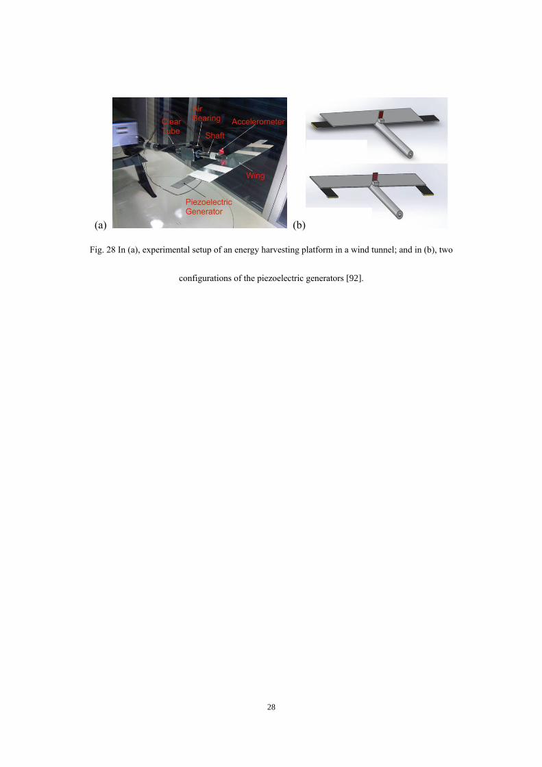
28
(a) (b)
Fig. 28 In (a), experimental setup of an energy harvesting platform in a wind tunnel; and in (b), two
configurations of the piezoelectric generators [92].

29
(a) (b)
Fig. 29 Schematic of (a) the experimental setup and (b) the pitch free-play mechanism [93]. Reprinted
with permission as per http://creativecommons.org/licenses/by-nc-nd/4.0/

30
(a) (b)
Fig. 30 Schematic of the experimental setup used to measure the harvesting capabilities of an IPMC
mounted on a heavy host flag [94]. IPMC denotes ionic polymer metal composites.

31
Fig. 31 Schematic of a cylinder with a hinged-rigid splitter plate. The rigid splitter plate was free to
rotate about the hinge at the base of the cylinder [95].

32
Fig. 32 Experimental setup of plate-based EH in axial flow [57].

33
Fig. 33 Schematic of the flexible heavy flag flapping in a uniform water stream comprising the host
structure and the ionic polymer metal composites strip [94].

34
Fig. 34 Schematic of different flapping leaf configurations [30].

35
Fig. 35 A schematic of the dual cantilever EH system [100].
Air Flow
y
x
U
Cantilever
Beams
u1(t)
u2(t)q
Gap

36
Fig. 36 Schematic of EH from galloping oscillations; from Ref. [101], © ASME, with permission.

37
(a) cylinder (b) triangle (c) pentagon (d) D-shaped (e) square
Fig. 37 Different cross sections of bluff bodies.

38
(a) (b)
Fig. 38 In (a) top and side views of the self-excited harvester, and in (b) electrode configuration for
patches [96]. (© IOP Publishing. Reproduced with permission. All rights reserved)
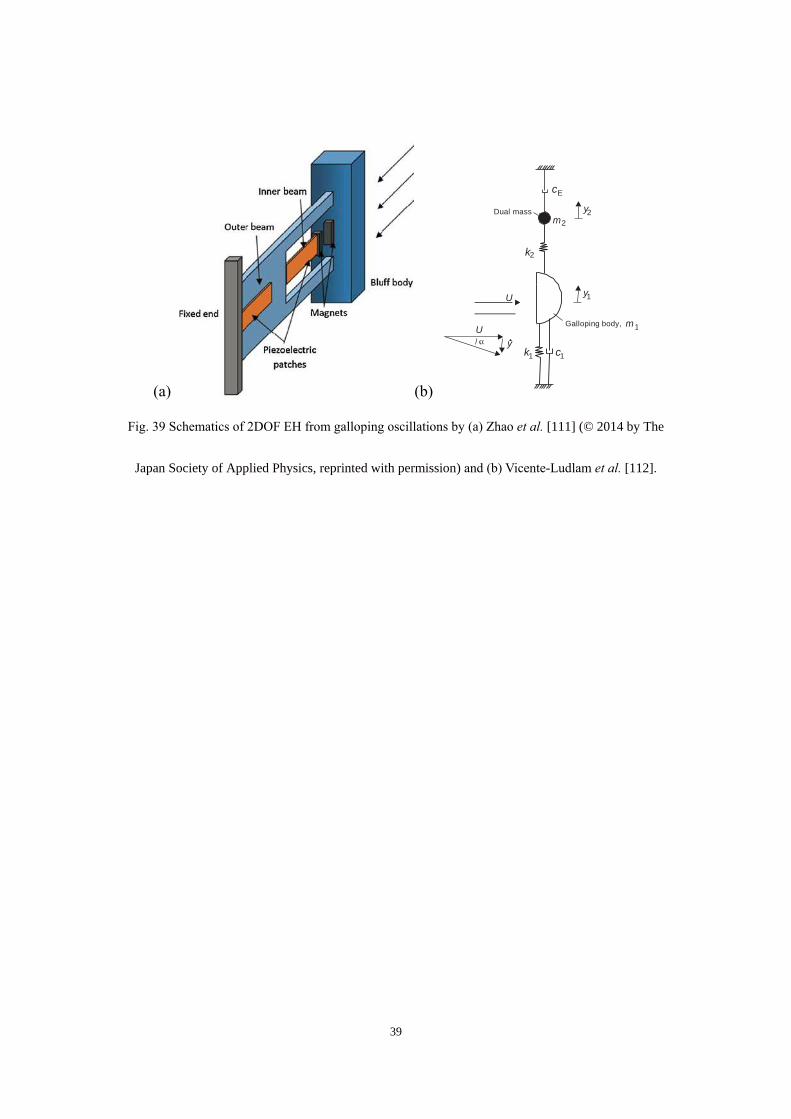
39
(a) (b)
Fig. 39 Schematics of 2DOF EH from galloping oscillations by (a) Zhao et al. [111] (© 2014 by The
Japan Society of Applied Physics, reprinted with permission) and (b) Vicente-Ludlam et al. [112].
U
U
y
y1
y2
Galloping body, m
Dual mass
k1 c1
cE
k2
1
m2

40
Fig. 40 Schematic of an aerofoil-based EH system [115].
Rigid airfoil
PZTSprings
Disturbance
Subsonic flow

41
Fig. 41 Aerofoil-based EH; from Ref. [116], © SPIE, with permission.

42
(a) (b)
Fig. 42 Schematic of modified aerofoil-based EH devices; in (a) from [87], and in (b) from [130]. (©
IOP Publishing. Reproduced with permission. All rights reserved)
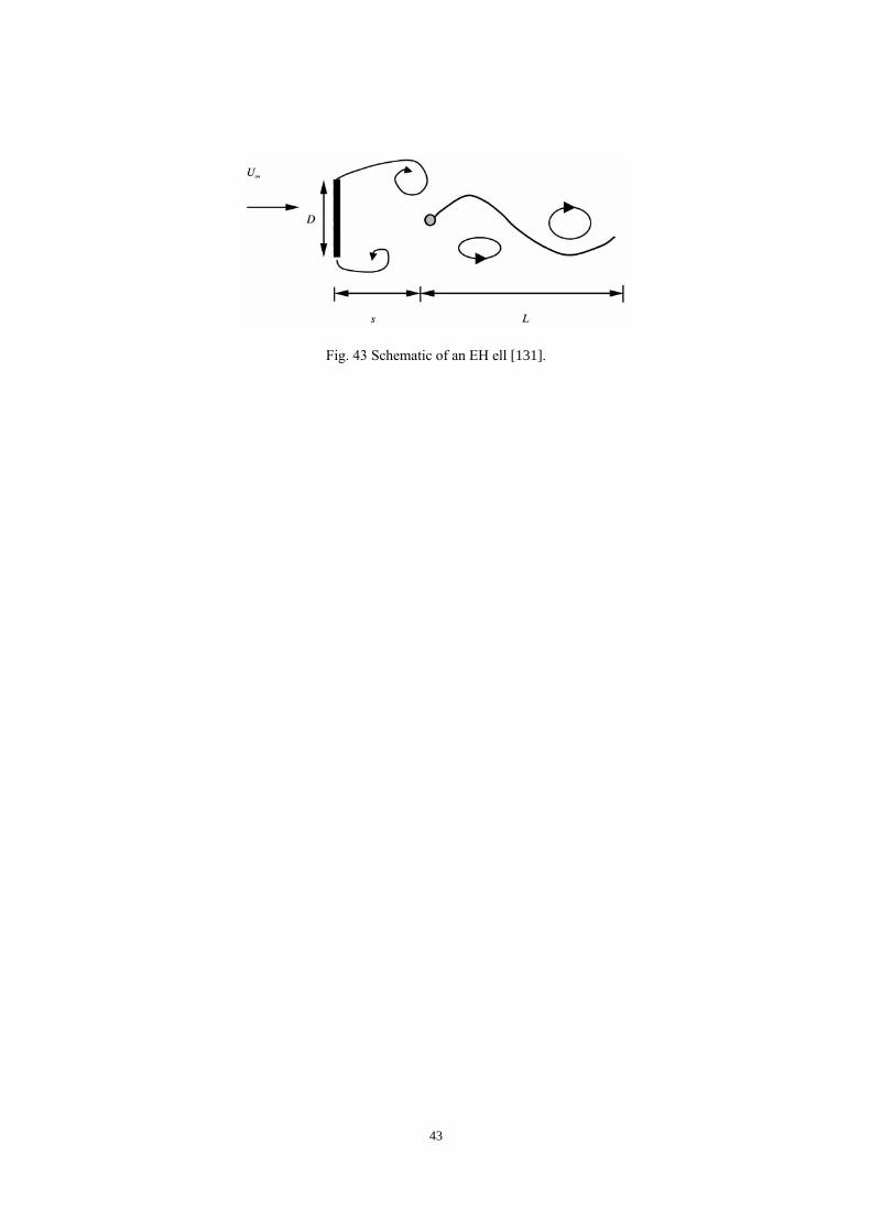
43
Fig. 43 Schematic of an EH ell [131].

44
Fig. 44 Schematic of EH from wake galloping phenomena [41]. (© IOP Publishing. Reproduced with
permission. All rights reserved)

45
Fig. 45 Schematic of EH based on variable flow via a membrane [142].
(a)
Pressure chamber
Flow source
Glass tube
Piezoelectric film
Flexible diaphragm
Nickel plate
Tank
Glass tube

46
Fig. 46 Schematic of EH based on blown airflow within a cavity [146].
Air blown out
Air chamber
Cantilever beam Air blown in
+ – Voltage
Piezoelectric layer

47
Fig. 47 Schematic of a wing-like plate; from Ref. [152], © ASME, with permission.

48
Fig. 48 Schematic of the piezoelectric wing spar [53].
z
xp
Lp
PZT
bp(x)
Wing sparhb(x)
x
bb(x)

49
Fig. 49 Remote control aircraft with modifications; from [159], © SPIE, with permission.

50
Fig. 50 Schematic of the multifunctional wing spar; from Ref. [161], © ASME, with permission.

51
Fig. 51 Photograph and schematic of Tyndall 25 mm wireless sensor module [168].
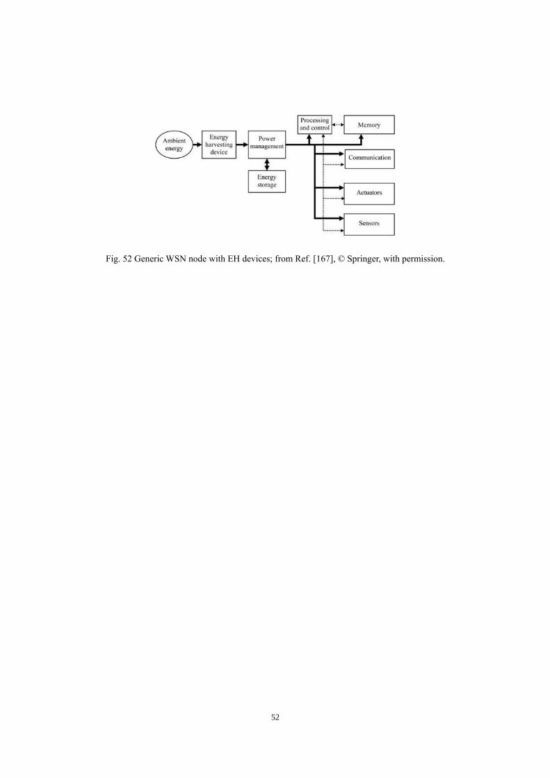
52
Fig. 52 Generic WSN node with EH devices; from Ref. [167], © Springer, with permission.

53
Fig. 53 Schematic of strain EH system; from Ref. [173], © SPIE, with permission.
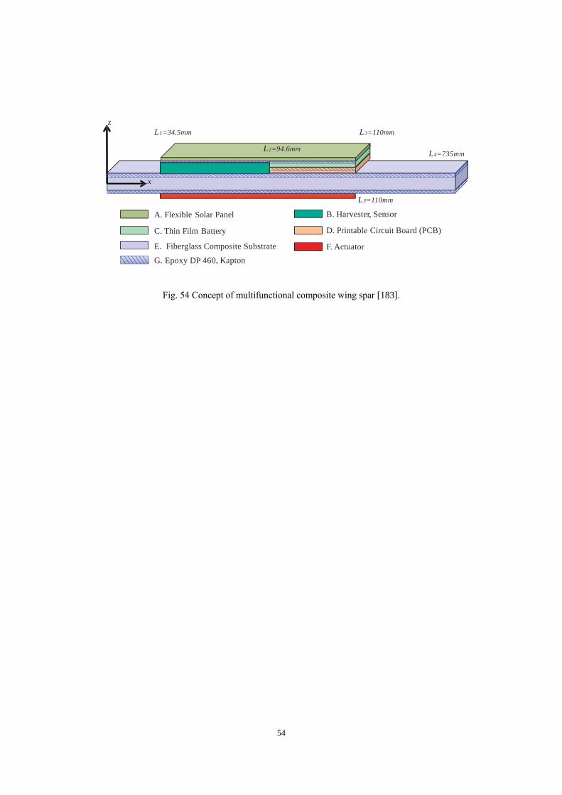
54
Fig. 54 Concept of multifunctional composite wing spar [183].
x
L3=110mm
z
A. Flexible Solar Panel
C. Thin Film Battery
E. Fiberglass Composite Substrate
G. Epoxy DP 460, Kapton
B. Harvester, Sensor
D. Printable Circuit Board (PCB)
F. Actuator
L1=34.5mm
L2=94.6mm
L3=110mm
L4=735mm

55
(a)
(b)
Fig. 55 In (a), dimensionless tip displacement frequency response function of multifunctional composite
wing spar, and in (b) harvested power spectrum at one optimal load resistance identified in [183].
101
102
-140
-80
-90
-100
-110
-120
-130
-70
Frequency [ Hz ]
Rela
tive
Tip
Dis
pla
cem
entF
RF
[dB
ref
1m
/g]
Analytical
Finite Element Method
101
102
10-10
10-5
100
Frequency [ Hz ]
Harv
este
dP
ow
er
[m
W ]

56
Fig. 56 Wind tunnel apparatus for demonstrating tab actuation powered by aerofoil-based harvester; from
Ref. [184], © SPIE, with permission.

57
Fig. 57 Apparatus for placing the aeroelastic energy harvester at an angle of attack in the flow; from Ref.
[184], © SPIE, with permission.