Embed Size (px)
Citation preview

Energy Systems Test Area (ESTA) Electrical Power System Test Operations
User Test Planning Guide
National Aeronautics and Space Administration Lyndon B. Johnson Space Center Houston, Texas 77058

JSC-XXXXX
2
Table of Contents 1.0 Introduction ..................................................................................................................4
1.1 Purpose .........................................................................................................................4
1.2 Facility Availability ..........................................................................................................4
1.3 Inquiries .........................................................................................................................4
1.4 Electrical Power System Test Operations ......................................................................5
1.5 Specifications .................................................................................................................6
1.5.1 Power Quality Testing ......................................................................................................... 6
1.5.2 Off-Nominal Testing ............................................................................................................ 6
1.5.3 High-Voltage Test Bed ........................................................................................................ 7
2.0 Facility Layout ..............................................................................................................8
3.0 Safety and Health .........................................................................................................9
4.0 Test Process Flow .......................................................................................................9
4.1 Export Controlled and Proprietary Information ............................................................. 10
4.2 Test Initiation Phase .................................................................................................... 11
4.2.1 Test Request .................................................................................................................... 11
4.2.2 Schedule and Cost Estimate ............................................................................................. 12
4.3 Test Preparation Phase ............................................................................................... 12
4.3.1 Test Requirements ........................................................................................................... 12
4.3.2 Test Article Documentation ............................................................................................... 12
4.3.3 Test Plan .......................................................................................................................... 13
4.3.4 Test Schedule ................................................................................................................... 13
4.3.5 Interface Control Document .............................................................................................. 14
4.3.6 Test Article Delivery .......................................................................................................... 14
4.3.7 Test Readiness Review .................................................................................................... 14
4.4 Test Execution Phase .................................................................................................. 15
4.4.1 Test Authority ................................................................................................................... 15
4.4.2 Test Deviations ................................................................................................................. 15
4.5 Test Closeout Phase .................................................................................................... 15
4.5.1 Data Package ................................................................................................................... 16
4.5.2 Customer Feedback ......................................................................................................... 16
5.0 Facility Access ........................................................................................................... 17

6.0 Roles and Responsibilities ....................................................................................... 18
Acronyms .................................................................................................................................. 19
Appendices ............................................................................................................................... 21
Appendix A Facility Interfaces/Sample Test Configurations ................................................. 22
Appendix B Test Request Worksheet ................................................................................... 25
Appendix C Data Acquisition System ................................................................................... 33
Appendix D Sample Test Plan .............................................................................................. 34
Appendix E Customer Feedback .......................................................................................... 41
1.0 Introduction The Johnson Space Center (JSC) has created and refined innovative analysis, design, development, and testing techniques that have been demonstrated in all phases of spaceflight. JSC is uniquely positioned to apply this expertise to components, systems, and vehicles that operate in remote or harsh environments. We offer a highly skilled workforce, unique facilities, flexible project management, and a proven management system.
1.1 Purpose The purpose of this guide is to acquaint Test Requesters with the requirements for test, analysis, or simulation services at JSC. The guide includes facility services and capabilities, inputs required by the facility, major milestones, a roadmap of the facility’s process, and roles and responsibilities of the facility and the requester. Samples of deliverables, facility interfaces, and inputs necessary to define the cost and schedule are included as appendices to the guide.
1.2 Facility Availability JSC test facilities are available for the National Aeronautics and Space Administration (NASA), other government agencies, and commercial requesters. We have developed user-friendly agreements to streamline business relationships and are eager to share our unique facilities and expertise. We invite your inquiries regarding application or adaptation of our capabilities to satisfy your special requirements. Briefings on general or specific subjects of mutual interest can be arranged at JSC or at your business site.
1.3 Inquiries General inquiries regarding the use of JSC facilities should be directed to:
JSC Engineering Directorate Johnson Space Center 2101 NASA Parkway, Houston, TX 77058 Phone: 281-483-8991 Email: [email protected]
Inquiries regarding electrical power system test operations at the Energy Systems Test Area (ESTA) should be directed to:
Martin McClean Energy Systems Test Area Branch Chief Johnson Space Center 2101 NASA Parkway, Houston, TX 77058 Phone: (281) 483-6478 Email: [email protected]
Please refer to the Engineering Services website: http://jsceng.nasa.gov, for additional information and general inquiries about test, analysis, and simulation capabilities at JSC.
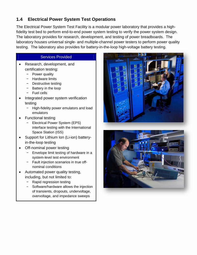
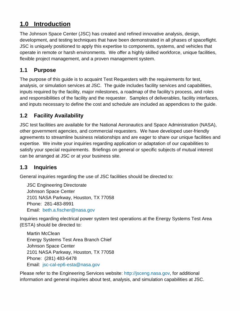
1.4 Electrical Power System Test Operations The Electrical Power System Test Facility is a modular power laboratory that provides a high-fidelity test bed to perform end-to-end power system testing to verify the power system design. The laboratory provides for research, development, and testing of power breadboards. The laboratory houses universal single- and multiple-channel power testers to perform power quality testing. The laboratory also provides for battery-in-the-loop high-voltage battery testing.
Services Provided
• Research, development, and certification testing: − Power quality − Hardware limits − Destructive testing − Battery in the loop − Fuel cells
• Integrated power system verification testing − High-fidelity power emulators and load
emulators • Functional testing
− Electrical Power System (EPS) interface testing with the International Space Station (ISS)
• Support for Lithium Ion (Li-ion) battery-in-the-loop testing
• Off-nominal power testing − Envelope limit testing of hardware in a
system-level test environment − Fault injection scenarios in true off-
nominal conditions • Automated power quality testing,
including, but not limited to: − Rapid regression testing − Software/hardware allows the injection
of transients, dropouts, undervoltage, overvoltage, and impedance sweeps

1.5 Specifications
1.5.1 Power Quality Testing
Capabilities
• Resistance Tests
• Short-Circuit Test
• Output Reference to Chassis
• Power Line to Chassis Isolation
• Current Transients and Steady-State Levels
• Inrush and Surge Current Transients
• Steady-State Current and Power Levels
• Step Load Transients
• Momentary Overload
• Voltage Range and Transients
• Power-On Rate
• Power-On Compatibility
• Switch Transition Time
• Steady-State Voltage
• Steady-State Voltage Drop
• Voltage Ripple and Noise
• Normal Voltage Transients
• Abnormal Voltage Transients
• Reverse Electromagnetic Force
• Fault Protection
• Impedance
• Electrical Power Reference
• Stand-Alone Stability
1.5.2 Off-Nominal Testing
Off-nominal testing includes integrated Failure Detection, Isolation, and Recovery (FDIR) power source, control, distribution, and load performance. Off-nominal testing supports both EPS verification and subsystems power quality verification.
Capabilities
• Injection of faults/failure conditions that can produce hazardous conditions
• Electrical hard and soft shorts at various points in the distribution system between sources and loads
• Bus voltage above specification per source failures
• Bus voltage below specification per source failures and overcurrent
• Load internal failures – opens, shorts, and high current
• Load internal failures – impedance changes, excessive noise, and random transients
• Command signal faults
• Electrical Ground Support Equipment (EGSE), Government-Furnished Equipment (GFE), and control panel [(SCRAM, PEPC, Extravehicular Activity (EVA)] failures
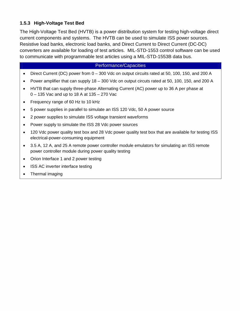
1.5.3 High-Voltage Test Bed
The High-Voltage Test Bed (HVTB) is a power distribution system for testing high-voltage direct current components and systems. The HVTB can be used to simulate ISS power sources. Resistive load banks, electronic load banks, and Direct Current to Direct Current (DC-DC) converters are available for loading of test articles. MIL-STD-1553 control software can be used to communicate with programmable test articles using a MIL-STD-1553B data bus.
Performance/Capacities
• Direct Current (DC) power from 0 – 300 Vdc on output circuits rated at 50, 100, 150, and 200 A
• Power amplifier that can supply 18 – 300 Vdc on output circuts rated at 50, 100, 150, and 200 A
• HVTB that can supply three-phase Alternating Current (AC) power up to 36 A per phase at 0 – 135 Vac and up to 18 A at 135 – 270 Vac
• Frequency range of 60 Hz to 10 kHz
• 5 power supplies in parallel to simulate an ISS 120 Vdc, 50 A power source
• 2 power supplies to simulate ISS voltage transient waveforms
• Power supply to simulate the ISS 28 Vdc power sources
• 120 Vdc power quality test box and 28 Vdc power quality test box that are available for testing ISS electrical-power-consuming equipment
• 3.5 A, 12 A, and 25 A remote power controller module emulators for simulating an ISS remote power controller module during power quality testing
• Orion Interface 1 and 2 power testing
• ISS AC inverter interface testing
• Thermal imaging

2.0 Facility Layout
Johnson Space Center (JSC) Building 361 Facility Layout*
* See Appendix A for facility interfaces and the facility layout.

3.0 Safety and Health Safety is an integral part of the culture at NASA. Management, leadership, and employee involvement from all organizations are critical to the success of NASA’s safety program. In order to ensure personal safety and a safe test environment throughout the process, the requester shall furnish the facility with the information necessary to perform a hazard assessment of the test article. Additionally, while visiting JSC, the requester shall follow all facility-specific safety and health requirements. A facility safety briefing shall be provided to all personnel prior to the start of the test. The safety briefing will include a review of the ESTA safety rules, potential hazards, and emergency procedures.
4.0 Test Process Flow The flowchart presented below outlines the basic roadmap and significant milestones between the initial test request and delivery of test data. The flow is separated between Test Requester actions and Facility actions, highlighting interactions and inputs between the Test Requester and the facility Test Director.

The test schedule is highly dependent on the complexity of the test, facility availability, and sequence of runs. A detailed schedule shall be developed following a review of the test objectives and requirements. For time-critical testing, this schedule may be accelerated. Major milestones are presented below:
4.1 Export Controlled and Proprietary Information ESTA provides for protection of export controlled and proprietary information and hardware throughout the test process. The Test Requester shall clearly mark all export controlled or proprietary hardware items and data provided with a notice of restriction on disclosure or usage. The Test Director shall safeguard export controlled or proprietary items from unauthorized use and disclosure and ensure that test articles remain secure within the facility and are properly sequestered. Hardware items shall be returned to the Test Requester or disposed of in accordance with the Test Requester’s instructions at the completion of the test activity.

4.2 Test Initiation Phase The test initiation phase establishes the relationship between the Test Requester and the Test Director. The Test Requester shall provide a test request to the Test Director, which will be used to determine test feasibility and to develop an estimated cost and a preliminary test schedule. An initial requirements review shall define the characteristics of the test article, test objectives, and special considerations for the test. An onsite tour of the facility is highly recommended for familiarization and to provide an opportunity for an exchange of technical information. Inputs: Test Requester provides test request, identifies Test Article Expert
Activities: Facility Test Director reviews test request to determine test feasibility
Outputs: Facility delivers preliminary test plan, estimated cost, and schedule to Test Requester
Test Requester concurs with estimated cost and schedule and provides necessary funding commitment to pay for test
4.2.1 Test Request
The test request outlines the test objectives, test article description, and schedule. A Test Request Worksheet is provided in Appendix B. This worksheet addresses the basic requirements for testing in the Electrical Power System Test Facility. It is suggested that the Test Requester complete this worksheet to facilitate the development of a preliminary test plan. Contact the Test Director if you have questions about completing the Test Request Worksheet. At a minimum, the test request should include the following information:
Test Objective
A brief description of the test requirements, including, but not limited to, the following:
• Test requirements (e.g., test matrix, test requirements document) • Proposed test approach • Test data requirements
Test Article Description
A brief description of the test article, including, but not limited to, the following:
• Size (provide drawings, sketches, photos) • Weight • Test article electrical interface • Test article interface requirements (provided by Test Requester/facility) • Special considerations [e.g., hazards, cleanliness, compatibility, Material Safety Data
Sheets (MSDS)]

• Handling and storage requirements
Schedule
Identify the required start date and proposed date for test completion.
4.2.2 Schedule and Cost Estimate
A cost and schedule estimate, including major milestones, will be delivered following receipt of the Test Request Worksheet. Test preparation will not begin until the Test Requester concurs with the estimated cost and schedule. The Test Requester must also provide the necessary funding commitment to pay for the test.
4.3 Test Preparation Phase The detailed test plan, test schedule, and Interface Control Document (ICD) are finalized during the test preparation phase. The Test Requester shall provide detailed test requirements and test article documentation to the Test Director. A Test Readiness Review (TRR) will be held following approval of the test plan. Inputs: Test Requester provides test requirements and test article documentation
Activities: Facility develops test plan, begins assembly of facility interface/support structure(s)
Test Requester ships/transports test article to JSC
Outputs: Test Requester approves test plan and test schedule
Facility holds TRR
4.3.1 Test Requirements
A complete understanding of test requirements is mandatory for a successful test. Test requirements must be defined and reviewed so that the test team understands the effect of the requirements on test facility preparation. The Test Requester shall provide a detailed list of test requirements, including, but not limited to, the following:
• Detailed test requirements • Interface requirements (e.g., electrical, mechanical) • Data/instrumentation requirements (provided by Test Requester and facility)
4.3.2 Test Article Documentation
Test Article Drawings
The Test Requester shall provide detailed test article drawings as requested by the facility. Test article drawings are used to prepare the facility interfaces, test article support structures, and instrumentation connection points.

Material Safety Data Sheets
NASA must ensure that all materials exposed to test environments do not present a hazard to personnel or the test facility. The Test Requester shall deliver to the facility MSDS for the supplied batteries with an assessment of expected byproducts produced during the test. The MSDS shall be delivered prior to delivery of the test article. The Test Director will review the MSDS for compatibility with the test environment and to determine protective measures for personnel, if required. Test Article Hazard Identification
The safety of facility personnel, facility equipment, and the test article is imperative to NASA. Potential hazards, material compatibility, and facility interfaces will be reviewed with the facility prior to testing. In certain instances, special precautions must be taken, due to the severity level of these potential hazards. The Test Requester may be asked to provide further information to clarify or mitigate a potential hazard. It is highly recommended that the Test Requester provide a test article hazard analysis or complete the Test Article Hazard Checklist included in Appendix B. The analysis should consider test article handling, support equipment, potential failure modes during the test, hazardous materials, batteries, high voltage/current devices, pressurized components, dangerous mechanical devices, sharp edges, and any other potential hazards.
4.3.3 Test Plan
A test plan will be prepared by the Test Director, unless one is submitted by the Test Requester. The final test plan shall be approved by the Test Requester with concurrence from the Test Director. The test plan will be the controlling document, with respect to scope and approach for the test program. The test plan will include, at a minimum, the test objectives, scope, test article description, safety considerations, and data requirements. Changes to the test plan that occur after the TRR, which result in a major change to the scope of the test or which present new hazards, may require a delta TRR. A sample test plan is included in Appendix D.
4.3.4 Test Schedule
A detailed schedule shall be developed by the Test Director and approved by the Test Requester. The schedule shall allow adequate time for review and approval of test requirements, assembly of facility interfaces/structures, and delivery of the test article. The schedule of other tests and maintenance activities will be reviewed and potential conflicts shall be addressed by the Test Director.

4.3.5 Interface Control Document
The ICD defines the interface between the test article and facility test equipment. An ICD will be prepared by the Test Director and approved by the Test Readiness Review Board (TRRB) with concurrence from the Test Requester. The ICD will include test fixture assembly requirements, a list and plot of specifications for the test, and test article interface drawings.
4.3.6 Test Article Delivery
The test article delivery date will be determined on a case-by-case basis. An agreed-upon delivery date shall be captured as a milestone in the test schedule. The Test Requester shall provide detailed handling instructions prior to delivery of the test article, including handling hazards, cleanliness, and storage requirements. An inspection of the test article shall be performed by the Test Director and the Test Article Expert prior to the start of testing. NASA encourages Test Article Expert participation in the test article integration phase to provide immediate feedback on test article handling and any integration issues that arise.
4.3.7 Test Readiness Review
A TRR will be held to ensure the completion of all necessary facility and test article activities prior to test execution. The TRR will include the following:
• Review of the test plan, test procedures, and other required test documentation • Confirmation of facility and test article readiness • Review of configuration records, including facility interface control documents, pressure
system certification, instrumentation calibration, and materials compatibility • Assurance that controls are in place to mitigate risks or hazards identified in the Test
Article Hazard Analysis • Verification that data acquisition and processing functions are in place to adequately
capture all critical data • Confirmation that multimedia coverage is adequate to provide recognition and
assessment of potential test anomalies Approval to proceed with test operations is granted by the TRRB. The Test Director shall ensure that all TRR actions have been accomplished prior to the start of the test. The TRRB shall convene 1 to 5 business days prior to the start of the test. TRRB participants shall include the following: NASA TRRB Chairman Test Article Expert (Appointed by Test Requester) Test Director Safety Engineer NASA Test Safety Officer Quality Engineer – if required by facility

4.4 Test Execution Phase NASA encourages Test Requester participation in the testing activity. The Test Requester shall provide a Test Article Expert to verify that test setup and execution meet the stated objectives. The Test Article Expert also shall verify test article performance and approve requested test deviations during test operations. Inputs: Approval to begin testing received from TRRB
Activities: Facility completes facility buildup, Detailed Test Procedure
Facility conducts testing activity
Outputs: Test completed
4.4.1 Test Authority
The Test Director has the authority and responsibility to direct the test in accordance with the approved test plan and to terminate test activities per test rules when danger is imminent or test control cannot be maintained. The Test Director will ensure that positive actions are taken to halt any steps in the test procedure whenever unsafe or hazardous test conditions arise. The Test Director, with the concurrence of the Test Article Expert, has the authority to terminate the test when sufficient data has been obtained to meet objectives or when objectives cannot be met. Test team personnel will accept directions only from the Test Director.
4.4.2 Test Deviations
Changes to the test procedure shall be approved by the Test Article Expert with concurrence from the Test Director. Deviations that result in a major change to the scope of the test or that present new hazards may require a delta TRR.
4.5 Test Closeout Phase Data shall be delivered to the Test Requester within 10 business days following completion of testing. The Test Requester shall notify the Test Director upon receipt of the data. Acceptance of the test data concludes the test activity. Inputs: Test completed
Activities: Facility ships/transports test article to Test Requester
Test Director delivers data to Test Requester
Outputs: Test Requester accepts data
Test Requester completes Customer Feedback form

4.5.1 Data Package
A data package is an assembly of test results. The format of the data package is normally specified by the Test Requester. The standard data package format includes a description of the test and objectives, test observations, test results, and data plots.
4.5.2 Customer Feedback
ESTA requests feedback from our customers. Evaluation of the services we provide enables continued improvement to our process. A Customer Feedback form is included in Appendix E. You are encouraged to complete the Customer Feedback form and return it to the Test Director, following receipt of the test data. Your participation is greatly appreciated.

5.0 Facility Access Identification badges are required for all persons requiring access to JSC. The Test Director or designee will initiate a badge request for all Test Requester personnel who will be participating in the test activity. Badge requests must be submitted at least 4 days prior to the visit to prevent badge processing delays. Badge requests for non-U.S. citizens may require a minimum of 30 business days to process. Test Requester personnel shall arrive at JSC Building 110 to pick up temporary identification badges. Visitors to JSC must show a current picture identification (valid driver’s license, U.S. passport, government ID card).
The Electrical Power System Test Facility is located in JSC Building 361. The facility is part of the ESTA identified on the map below. Test Requester personnel shall arrive at JSC Building 350, ESTA Main Office, to complete a facility access briefing prior to arriving at JSC Building 361.

6.0 Roles and Responsibilities
Test Director – Has overall responsibility for all phases of the test process. Test Requester – The client requesting performance of a test activity. The Test Requester is responsible for the test article and for providing a Test Article Expert. Test Article Expert – A representative of the Test Requester with thorough knowledge of the test article and how it is to be operated in the test environment. The Test Article Expert also is responsible for approving the test plan and verifying that test objectives are met. Facility Engineering – Responsible for designing and fabricating any required test article interfaces, including structures, fluids, and power. Facility engineering also provides support for external test article instrumentation and data acquisition. Safety Engineer – Reviews the test article hazard assessment and prepares an integrated hazard analysis for the test facility to identify any additional hazards that could result from mating the test article to the test facility. Quality Engineer – Responsible for verifying that the test facility is ready for the test by ensuring that all constraints to the test have been closed. Responsibilities Matrix
Item Test Requester Facility
Test Request Worksheet Create Review and provide assistance as needed
Cost and schedule Approve Create and sign off
Hazards Identify test article hazards Create test article/facility integrated hazard analysis
Test plan Review and approve Create and sign off
Test Readiness Review Approve Conduct and approve
Test execution
Verify test article performance Verify that test setup and execution meet objectives Approve requested deviations
Execute test
Provide test data/results Notify Test Director of data receipt Deliver to Test Requester
Review test data/results Approve Shipping Provide instruction Execute per request

Acronyms
A Amperes
AC Alternating Current
ASCII American Standard Code for Information Interchange
DAQ Data Acquisition
dBA decibel A-weighting
DC Direct Current
DC-DC Direct Current to Direct Current
DMM Demultiplexer Modulator
EGSE Electrical Ground Support Equipment
EPS Electrical Power System
ESTA Energy Systems Test Area
EVA Extravehicular Activity
FDIR Failure Detection, Isolation, and Recovery
ft feet
FTP File Transfer Protocol
GFE Government-Furnished Equipment
GUI Graphical User Interface
H Height
hr hour(s)
HVTB High Voltage Test Bed
Hz Hertz
ICD Interface Control Document
IR Infrared
ISS International Space Station
JSC Johnson Space Center
kHz Kilohertz
L Length
lb pound(s)
Li-ion Lithium Ion
MSDS Material Safety Data Sheets

N/A Not Applicable
NASA National Aeronautics and Space Administration
Ni-Cd Nickel-Cadmium
NiMH Nickel-Metal Hydride
PCB Printed Circuit Board
PCU Power Control Unit
PDU Power Distribution Unit
PQ Power Quality
PXI PCI Extentions for Instrumentation
R2 Robonaut 2
RF Radio Frequency
RTD Resistance Temperature Detector
SPS Samples Per Second
TC Temperature Control
TDR Time Domain Reflectometer
TRR Test Readiness Review
TRRB Test Readiness Review Board
UV Ultraviolet
V Volt(s)
Vac Volts of Alternating Current
Vdc Volts of Direct Current
W Width

Appendices A. Facility Interfaces/Sample Test Configurations
B. Test Request Worksheet
C. Data Acquisition System
D. Sample Test Plan
E. Customer Feedback

Appendix A Facility Interfaces/Sample Test Configurations
The test article interface diagrams included in this guide are a sampling of the capabilities within ESTA. The facility maintains a variety of fixtures to support general and requester-specific testing. Additional test interfaces are available upon request. The facility also can manufacture test fixtures to requester specifications. Contact the Test Director to discuss test article interface requirements.
Modular Power Breadboard
Single Channel Power Quality Tester
• 4PDU/PCU combinations (split bus versions) − Design able to support cold plates with Litron
chillers to support active heat loads • Emulator rack supplies 500 V 10 A sources (2). • 2 load racks with 2 – 500 V 10 A loads, 18 – 150 V
10 A loads, and 20 500 V resistive loads • 2 solar arrays capable of supplying 120 V each at 30
A • Support 6 – 1,000 A 600 V switching per unit • Standard circular 4 pin connector used by ESTA
testers to sources and loads as well as Wago terminal for any interface required
• Standard E-STOP rack mount cabinet • Standard PXI data and control system to support all
interfaces voltage and current measurements with a fixed current shunt/sensor
• Standard PXI based temperature monitoring for up to 32 type T TC’s
• Standard Labview VI to allow for standard GUI

Modular Battery Tester

Modular Battery Tester
Example Power Quality Test Setup

Appendix B Test Request Worksheet Test Requester Information Test Article Expert:
Contact Information (Phone, E-mail, Address):
Test Objectives Purpose of Test:
Proposed Test Start Date:
Critical Test Start Date:
Test Article Test Article Description:
Physical Dimensions (L/W/H):
Weight:
EQUPMENT LOCK LID

Batteries Model Number: Capacity: Nominal Voltage:
Mass (entire assembly): Watt Hours (entire assembly): Number of Cells Delivered:
Volume (individual cells):
Cell Configuration:
Description of any smart circuitry:
Chemistry (Alkaline, Ni-Cad, Ni-MH, Li-ion, Other):
Charge Schedule (current, voltage, time)
Discharge Schedule (current, voltage, time):
Battery Safety Limits:
Operational Requirements Functional Checks (Describe any functional checks to be performed prior to, during, or after testing):
Test Article Limitations (High/low cutoff temperature, ramp rate not to exceed):
Continuous Operations (24 hr): Authorized Shutdown Points:

Test Article Handling Requirements Cleanliness Level:
Controlled Access:
Special Moving/Handling:
Storage Requirements:
Power Quality Test Requirements
Provide all power quality test requirements and proposed test requirements (specifications to be met, or specific standards):
Requirement Test Method
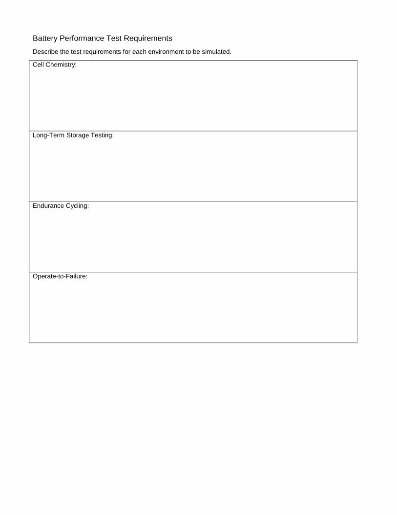
Battery Performance Test Requirements
Describe the test requirements for each environment to be simulated.
Cell Chemistry:
Long-Term Storage Testing:
Endurance Cycling:
Operate-to-Failure:

Test Article Interface Test Article Interface Design (Facility or Requester designed, drawings attached, instructions):
Test Fixture (facility stock, facility fabricated, or requester provided):
Power Supply (Describe power supply to test article; include voltage, current, and connections):
List materials and instruments supplied by Requester (connectors supplied):
Designs/Drawings
We can accept files through a File Transfer Protocol (FTP) site, by e-mail, or via standard mail.
1. E-mail drawings to [email protected]. 2. The Test Director will send an invitation to the NASA FTP site to upload and send files. 3. Mail drawings to National Aeronautics and Space Administration, Attention Martin McClean, Mail Code
EP6, Lyndon B. Johnson Space Center, Houston, TX 77058

Instrumentation Instrumentation (type of instrumentation, number; attach diagram of planned sensor locations):
Instrumentation Provided by Test Requester:
Data Acquisition and Recording Number of Channels:
Video Recording (Yes/No):
Sampling Rates:
Photographic Film (Yes/No):
Real-Time Data Processing (Yes/No):
High Speed/Low Speed (Video):
Data File (ASCII/Excel):
Plots (Yes/No):
Other Information List any other information pertinent to the test:

Test Article Hazard Checklist A hazard analysis statement is required for any of the following applicable attributes of any of your provided hardware (e.g., test article, support equipment).
Hazard Y N Comments
Mechanical
Handling (> 40 lb or > 4 ft in any dimension)
Instability
Sharp Edges
Pinch Points
Exposed Mechanisms (e.g., rotating, reciprocating)
Pressure Systems
Stored Energy (e.g., springs, weights, flywheels)
Ejected Parts, Projectiles
Electrical
Voltage (> 50 volts)
Batteries
Generation/Storage (e.g., coils, magnets, capacitors)
Electrostatic Sensitive Devices
Thermal
Hot Surfaces (> 113 °F, 45 °C)
Heaters
Cold Surfaces (< 39 °F, 4 °C)
Cooling Devices

Hazard Y N Comments
Radiation
Ionizing
Non-Ionizing
Laser
Microwave
Infrared (IR)
Ultraviolet (UV)
Radio Frequency (RF)
Visible Light, High Intensity
Material
Uncontained Brittle Materials
Test Environment Incompatibility
Contained Fluids
Toxic, Corrosive, Flammable Fluids
Biohazards
Miscellaneous
Noise Level (> 85 dBA)
Ultrasonic
Pyrotechnics/Explosives
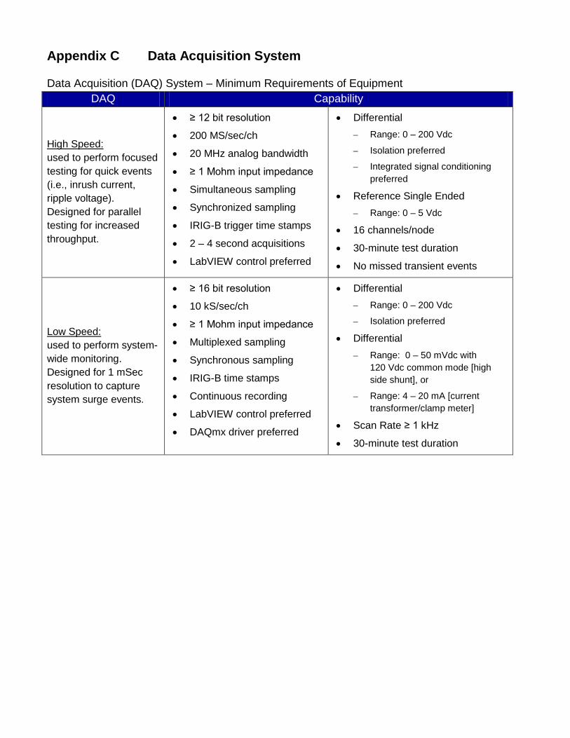
Appendix C Data Acquisition System
Data Acquisition (DAQ) System – Minimum Requirements of Equipment DAQ Capability
High Speed: used to perform focused testing for quick events (i.e., inrush current, ripple voltage). Designed for parallel testing for increased throughput.
• ≥ 12 bit resolution
• 200 MS/sec/ch
• 20 MHz analog bandwidth
• ≥ 1 Mohm input impedance
• Simultaneous sampling
• Synchronized sampling
• IRIG-B trigger time stamps
• 2 – 4 second acquisitions
• LabVIEW control preferred
• Differential – Range: 0 – 200 Vdc
– Isolation preferred
– Integrated signal conditioning preferred
• Reference Single Ended – Range: 0 – 5 Vdc
• 16 channels/node
• 30-minute test duration
• No missed transient events
Low Speed: used to perform system-wide monitoring. Designed for 1 mSec resolution to capture system surge events.
• ≥ 16 bit resolution
• 10 kS/sec/ch
• ≥ 1 Mohm input impedance
• Multiplexed sampling
• Synchronous sampling
• IRIG-B time stamps
• Continuous recording
• LabVIEW control preferred
• DAQmx driver preferred
• Differential – Range: 0 – 200 Vdc
– Isolation preferred
• Differential – Range: 0 – 50 mVdc with
120 Vdc common mode [high side shunt], or
– Range: 4 – 20 mA [current transformer/clamp meter]
• Scan Rate ≥ 1 kHz
• 30-minute test duration

Appendix D Sample Test Plan Test Requester Information Test Article Expert:
[Identify Test Article Expert]
Contact Information (Phone, E-mail, Address):
[Test Article Expert Contact Information]
Test Objectives Purpose of Test:
Provide stated primary and secondary objectives. Wherever possible, specific goals and/or limitations should be included. The primary objectives are to be interpreted as minimum achievements for test success, and the secondary objectives are considered highly desirable options. Sample Objective: The primary objective of this program is to perform an engineering evaluation on TA1 by performing the following tests: functional voltage check, reverse current, and current limiting.
Proposed Test Start Date:
Proposed Start Date
Proposed Test Start Date:
Proposed Start Date
Test Article Test Article Description:
Technical description of the test article, defining method of operation and theoretical considerations, referring to drawings and/or schematics if necessary. Operational characteristics including normal and off-limit performance parameters, such as temperature, thrust, voltage, current, and flow rate. Operational constraints of the test article that cannot be violated without harming the test article (for example, pressure limits, environmental temperature limits, vibration levels, system cleanliness, and fluid purity).
Physical Dimensions (L/W/H): X″ in length and X″ in diameter
Physical Dimensions (L/W/H): X″ in length and X″ in diameter

Batteries Model Number: Capacity: Nominal Voltage:
Mass (entire assembly): Watt Hours (entire assembly): Number of Cells Delivered:
Volume (individual cells):
Cell Configuration:
Description of any smart circuitry:
Chemistry (Alkaline, Ni-Cad, Ni-MH, Li-ion, Other):
Charge Schedule (current, voltage, time)
Discharge Schedule (current, voltage, time):
Battery Safety Limits:
Operational Requirements Functional Checks (Describe any functional checks to be performed prior to, during, or after testing):
Test Requester will verify nominal performance of VA1 prior to each test series.
Test Article Limitations (High/low cutoff temperature, ramp rate not to exceed):
All tests are to be stopped after the temperature drops to less than 50 °C after any event
Continuous Operations (24 hr): No Continuous Operations (24 hr): No
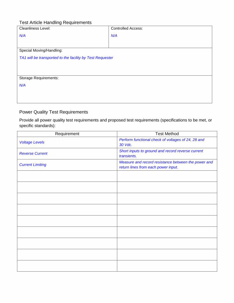
Test Article Handling Requirements Cleanliness Level:
N/A
Controlled Access:
N/A
Special Moving/Handling:
TA1 will be transported to the facility by Test Requester
Storage Requirements:
N/A
Power Quality Test Requirements
Provide all power quality test requirements and proposed test requirements (specifications to be met, or specific standards):
Requirement Test Method
Voltage Levels Perform functional check of voltages of 24, 28 and 30 Vdc.
Reverse Current Short inputs to ground and record reverse current transients.
Current Limiting Measure and record resistance between the power and return lines from each power input.

Battery Performance Test Requirements
Describe the test requirements for each environment to be simulated
Cell Chemistry:
Long-Term Storage Testing:
Endurance Cycling:
Operate-to-Failure:

Test Article Interface Test Article Interface Design (Facility or Requester designed, drawings attached, instructions):
Facility designed/provided
Test Fixture (facility stock, facility fabricated, or requester provided):
A table to hold the test article and associated equipment will be required.
Power Supply (Describe power supply to test article; include voltage, current, and connections):
Facility power to power TA1 power supplies and test article supporting equipment will be required.
List materials and instruments supplied by Requester (connectors supplied):

Instrumentation Instrumentation (type of instrumentation, number; attach diagram of planned sensor locations):
Identify requirements for instrumentation, data recording, displays, and data processing.
Instrumentation diagram attached
Instrumentation Provided by Test Requester:
Identify instrumentation; data recording to be provided to the facility.
Data Acquisition and Recording Number of Channels:
32
Video Recording (Yes/No):
Yes
Sampling Rates:
10 SPS
Photographic Film (Yes/No):
Yes, pretest, posttest, and test setup
Real-Time Data Processing (Yes/No):
No
High Speed/Low Speed (Video):
High Speed
Data File (ASCII/Excel):
Excel
Plots (Yes/No):
No
Other Information List any other information pertinent to the test:

Test Article Hazard Checklist A hazard analysis statement is required for any of the following applicable attributes of any of your provided hardware (e.g., test article, support equipment).
Hazard Y N Comments
Mechanical Identify the hazards and present the approach for mitigating each
Handling (> 40 lb or > 4 ft in any dimension)
Instability
Sharp Edges
Pinch Points
Exposed Mechanisms (e.g., rotating, reciprocating)
Pressure Systems
Stored Energy (e.g., springs, weights, flywheels)
Ejected Parts, Projectiles
Electrical
Voltage (> 50 volts)
Batteries
Generation/Storage (e.g., coils, magnets, capacitors)
Electrostatic Sensitive Devices
Thermal
Hot Surfaces (> 113 °F, 45 °C)
Heaters
Cold Surfaces (< 39 °F, 4 °C)
Cooling Devices

Appendix E Customer Feedback
EP TEST REQUESTER FEEDBACK (ESTA & EPSL) Test Number/Title: Date:
Test Requester/Org (Optional): Facility:
SCORE * 1= Poor, 5 = Excellent
SCHEDULE: 1. Was the test initiated and completed to meet your requirements/test
objectives? _____
2. Was the test performed within the agreed to schedule? _____
3. Was the test data/report provided to you in a timely manner? _____
COST:
1. Was the test performed within the estimated cost? _____
2. Was the test cost reasonable for the test performed? _____
PRODUCT:
1. Was the provided test data/report sufficient? _____
2. Was the test data/report provided to you in an acceptable format? _____
3. Were the objectives of the test satisfied? _____
SAFETY: 1. Was safety during test operations adequately addressed and
controlled? _____
2. Was test article handling and use safe while in the care of the test facility/personnel? _____
FACILITY/TEST TEAM:
1. Did the facility’s capability meet the needs of the test requirements? _____
2. Was the facility reliable during the test? _____
3. Did you find the test team helpful and knowledgeable in meeting your objective _____
4. Would you consider using this test facility for future tests? _____ * If score is below 3, please provide comment below.
COMMENTS/Suggestions for Improvements or Future Capability Needs:
Note: We are concerned and interested in your comments and would like an opportunity to improve our service. RETURN TO: Mail code EP/Test Feedback (or e-mail to [email protected])