Embed Size (px)
Citation preview
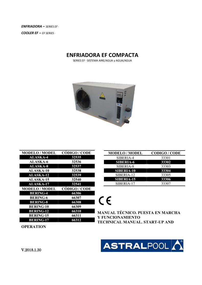
ENFRIADORA – SERIES EF · COOLER EF – EF SERIES ·
ENFRIADORA EF COMPACTA SERIES EF · SISTEMA AIRE/AGUA y AGUA/AGUA
MANUAL TÉCNICO. PUESTA EN MARCHA Y FUNCIONAMIENTO TECHNICAL MANUAL. START-UP AND
OPERATION V.2018.1.30
MODELO / MODEL CODIGO / CODE SIBERIA-4 33301 SIBERIA-6 33302 SIBERIA-8 33303
SIBERIA-10 33304 SIBERIA-12 33305 SIBERIA-15 33306 SIBERIA-17 33307
MODELO / MODEL CÓDIGO / CODE ALASKA-4 32535 ALASKA-6 32536 ALASKA-8 32537 ALASKA-10 32538 ALASKA-12 32539 ALASKA-15 32540 ALASKA-17 32541
MODELO / MODEL CÓDIGO / CODE BERING-4 66306 BERING-6 66307 BERING-8 66308 BERING-10 66309 BERING-12 66310 BERING-15 66311 BERING-17 66312

ENFRIADORA EF COMPACTA SERIES EF · ENFRIADORA DE PISCINA
ENFRIADORA– SERIES EF · COOLER EF – EF SERIES ·
TECHNICAL MANUAL. START-UP AND OPERATION MANUAL TÉCNICO. PUESTA EN MARCHA Y FUNCIONAMIENTO
© TALLERES DEL AGUA S.L. 2008. TODOS LOS DERECHOS RESERVADOS. DOCUMENTO CONFIDENCIAL Y EN PROPIEDAD.
Page 4 of 53
ESPAÑOL
. INTRODUCCION.......................................................................................................................................
. MODELOS ...............................................................................................................................................
. PRECAUCIONES DE EMPLEO Y CONDICIONES DE USO .............................................................................. . Des ip ió ...................................................................................................................................... . Des ip ió del e uipo ..................................................................................................................... . Cuad o elé t i o ...............................................................................................................................
. CARACTERISTICAS TECNICAS ...................................................................................................................
. POTENCIA ENTREGADA Y CONSUMIDA ....................................................................................................
. ESQUEMA DE DIMENSIONES ...................................................................................................................
. CARACTERISTICAS ELECTRICAS ................................................................................................................
. REGULADOR ............................................................................................................................................
. PRECAUCIONES GENERALES .................................................................................................................... . COMPROBACION DEL EMBALAJE ............................................................................................................. . CONDICIONES DE TRABAJO ..................................................................................................................... . REQUISITOS Y OPERACIONES PREVIAS ..................................................................................................... . CONEXIONES ELECTRICAS ........................................................................................................................ . CONEXIONES HIDRAULICAS ..................................................................................................................... . OPERACIÓN DE PUESTA EN MARCHA ....................................................................................................... . MANTENIMIENTO PREVENTIVO ............................................................................................................... . AVERIAS, SUS CAUSAS Y SOLUCIONES ...................................................................................................... . CARGA DE GAS REFRIGERANTE ................................................................................................................ . GARANTIA Y CONDICIONES GENERALES ................................................................................................... . RECICLAJE DEL PRODUCTO ......................................................................................................................
INDICE
© TALLERES DEL AGUA S.L. 2008. TODOS LOS DERECHOS RESERVADOS. DOCUMENTO CONFIDENCIAL Y EN PROPIEDAD.
Page 5 of 53
ENGLISH
. INTRODUCTION ....................................................................................................................................... . MODELS .................................................................................................................................................. . GENERAL FEATURES ................................................................................................................................
. Des iptio .......................................................................................................................................
. Des iptio of e uip e t .................................................................................................................
. Ele t i al pa el ................................................................................................................................. . TECHNICAL CHARACTERISTICS ................................................................................................................. . GIVEN AND CONSUMED POWER ............................................................................................................. . DIMMENSIONS DATA .............................................................................................................................. . ELECTRICAL CHARACTERISTICS ................................................................................................................ . REGULATOR ............................................................................................................................................ . GENERAL PRECAUTIONS ..........................................................................................................................
. PACKAGING INSPECTION .........................................................................................................................
. OPERATING CONDITIONS ........................................................................................................................
. REQUIREMENTS AND PROCEDURES .........................................................................................................
. ELECTRICAL CONNECTIONS .....................................................................................................................
. HYDRAULIC CONNECTIONS ......................................................................................................................
. PROCEDURES AND START-UP ..................................................................................................................
. PREVENTIVE MAINTENANCE ....................................................................................................................
. TROUBLESHOOTING GUIDE .....................................................................................................................
. REFIREGERANT GAS CHARGE ...................................................................................................................
. WARRANTY AND GENERAL CONDITIONS .................................................................................................
. PRODUCT RECYCLING ..............................................................................................................................
INDEX
© TALLERES DEL AGUA S.L. 2008. TODOS LOS DERECHOS RESERVADOS. DOCUMENTO CONFIDENCIAL Y EN PROPIEDAD.
Page 6 of 53
ESPAÑOL
© TALLERES DEL AGUA S.L. 2008. TODOS LOS DERECHOS RESERVADOS. DOCUMENTO CONFIDENCIAL Y EN PROPIEDAD.
Page 7 of 53
ESPAÑOL
IMPORTANTE Le rogamos al cliente o instalador lea detenidamente este manual con el fin de: Realizar una correcta instalación y puesta en marcha. Conocer todas las potencialidades de la máquina, y tener en cuenta todas las
circunstancias necesarias para su correcto y duradero funcionamiento.
ENFRIADORA AIRE/AGUA – AGUA/AGUA EF COMPACTA
SERIES EF Sistema Aire/Agua y Agua/Agua
1. INTRODUCCIÓN Gracias por adquirir la ENFRIADORA EF fabricada por Talleres del Agua. La experiencia acumulada por nuestra compañía durante más de 20 años en el mundo de la climatización de piscinas ha sido puesta a su servicio en este producto.
LE RECOMENDAMOS ANOTE LOS SIGUIENTES DATOS
APARATO
Nº REFERENCIA MODELO
INSTALADOR
NOMBRE POBLACIÓN
DOMICILIO
TELÉFONO FECHA DE PUESTA EN MARCHA
USUARIO
NOMBRE POBLACIÓN
DOMICILIO
TELÉFONO FECHA DE PUESTA EN MARCHA
(A rellenar por el instalador) SELLO DEL INSTALADOR:
Para todas las máquinas, se deberá cumplimentar y enviar esta tarjeta de garantía para que entre en vigor
© TALLERES DEL AGUA S.L. 2008. TODOS LOS DERECHOS RESERVADOS. DOCUMENTO CONFIDENCIAL Y EN PROPIEDAD.
Page 8 of 53
ESPAÑOL
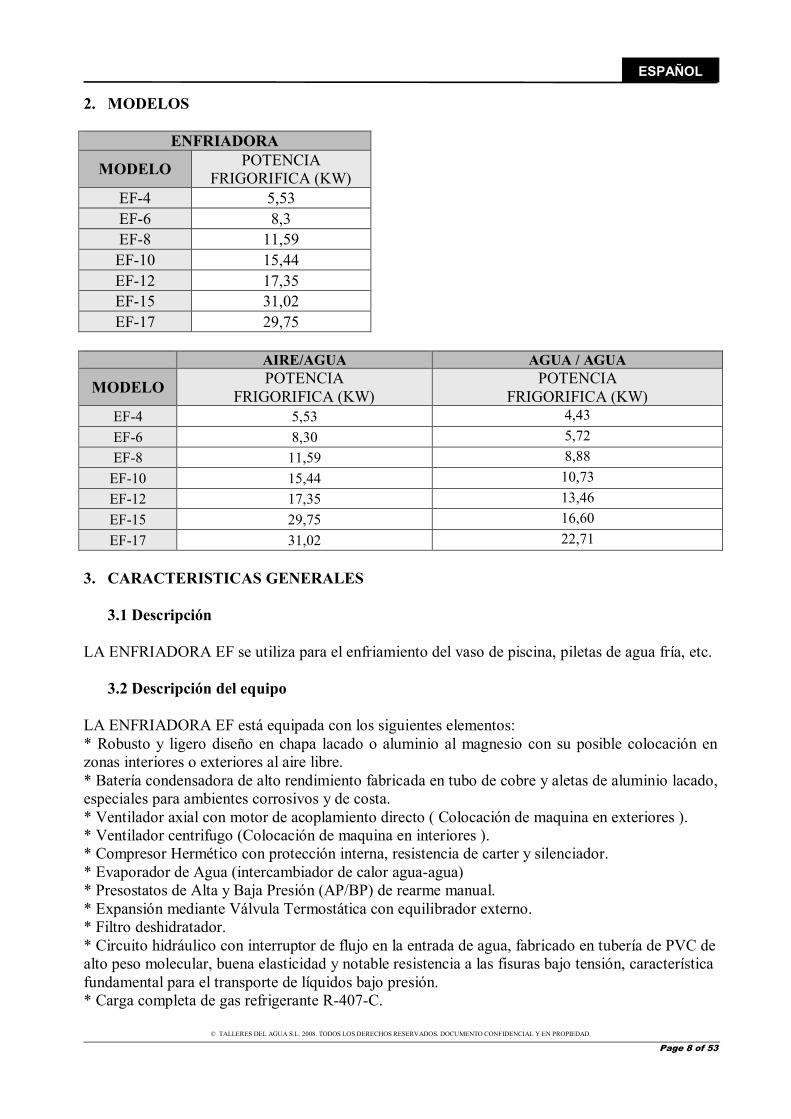
2. MODELOS
ENFRIADORA
MODELO POTENCIA FRIGORIFICA (KW)
EF-4 5,53 EF-6 8,3 EF-8 11,59 EF-10 15,44 EF-12 17,35 EF-15 31,02 EF-17 29,75
3. CARACTERISTICAS GENERALES
3.1 Descripción LA ENFRIADORA EF se utiliza para el enfriamiento del vaso de piscina, piletas de agua fría, etc.
3.2 Descripción del equipo LA ENFRIADORA EF está equipada con los siguientes elementos: * Robusto y ligero diseño en chapa lacado o aluminio al magnesio con su posible colocación en zonas interiores o exteriores al aire libre. * Batería condensadora de alto rendimiento fabricada en tubo de cobre y aletas de aluminio lacado, especiales para ambientes corrosivos y de costa. * Ventilador axial con motor de acoplamiento directo ( Colocación de maquina en exteriores ). * Ventilador centrifugo (Colocación de maquina en interiores ). * Compresor Hermético con protección interna, resistencia de carter y silenciador. * Evaporador de Agua (intercambiador de calor agua-agua) * Presostatos de Alta y Baja Presión (AP/BP) de rearme manual. * Expansión mediante Válvula Termostática con equilibrador externo. * Filtro deshidratador. * Circuito hidráulico con interruptor de flujo en la entrada de agua, fabricado en tubería de PVC de alto peso molecular, buena elasticidad y notable resistencia a las fisuras bajo tensión, característica fundamental para el transporte de líquidos bajo presión. * Carga completa de gas refrigerante R-407-C.
AIRE/AGUA AGUA / AGUA
MODELO POTENCIA FRIGORIFICA (KW)
POTENCIA FRIGORIFICA (KW)
EF-4 5,53 4,43 EF-6 8,30 5,72 EF-8 11,59 8,88
EF-10 15,44 10,73 EF-12 17,35 13,46 EF-15 29,75 16,60 EF-17 31,02 22,71
© TALLERES DEL AGUA S.L. 2008. TODOS LOS DERECHOS RESERVADOS. DOCUMENTO CONFIDENCIAL Y EN PROPIEDAD.
Page 9 of 53
ESPAÑOL
* Un circuito frigorífico de cobre nitrogenado, deshidratado y desoxidado.
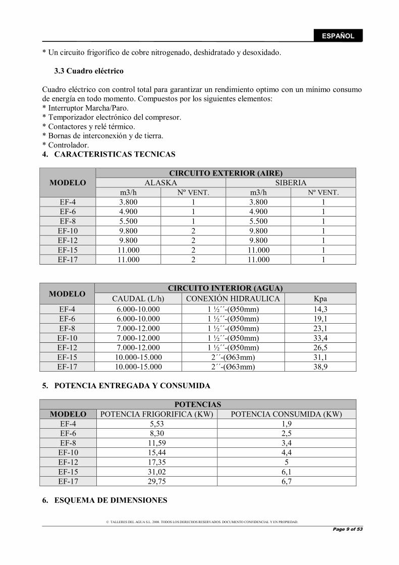
3.3 Cuadro eléctrico Cuadro eléctrico con control total para garantizar un rendimiento optimo con un mínimo consumo de energía en todo momento. Compuestos por los siguientes elementos: * Interruptor Marcha/Paro. * Temporizador electrónico del compresor. * Contactores y relé térmico. * Bornas de interconexión y de tierra. * Controlador. 4. CARACTERISTICAS TECNICAS
MODELO CIRCUITO EXTERIOR (AIRE)
ALASKA SIBERIA m3/h Nº VENT. m3/h Nº VENT.
EF-4 3.800 1 3.800 1 EF-6 4.900 1 4.900 1 EF-8 5.500 1 5.500 1
EF-10 9.800 2 9.800 1 EF-12 9.800 2 9.800 1 EF-15 11.000 2 11.000 1 EF-17 11.000 2 11.000 1
MODELO CIRCUITO INTERIOR (AGUA)
CAUDAL (L/h) CONEXIÓN HIDRAULICA Kpa EF-4 6.000-10.000 1 ½´´-(Ø50mm) 14,3 EF-6 6.000-10.000 1 ½´´-(Ø50mm) 19,1 EF-8 7.000-12.000 1 ½´´-(Ø50mm) 23,1 EF-10 7.000-12.000 1 ½´´-(Ø50mm) 33,4 EF-12 7.000-12.000 1 ½´´-(Ø50mm) 26,5 EF-15 10.000-15.000 2´´-(Ø63mm) 31,1 EF-17 10.000-15.000 2´´-(Ø63mm) 38,9
5. POTENCIA ENTREGADA Y CONSUMIDA
POTENCIAS MODELO POTENCIA FRIGORIFICA (KW) POTENCIA CONSUMIDA (KW)
EF-4 5,53 1,9 EF-6 8,30 2,5 EF-8 11,59 3,4 EF-10 15,44 4,4 EF-12 17,35 5 EF-15 31,02 6,1 EF-17 29,75 6,7
6. ESQUEMA DE DIMENSIONES
© TALLERES DEL AGUA S.L. 2008. TODOS LOS DERECHOS RESERVADOS. DOCUMENTO CONFIDENCIAL Y EN PROPIEDAD.
Page 10 of 53
ESPAÑOL
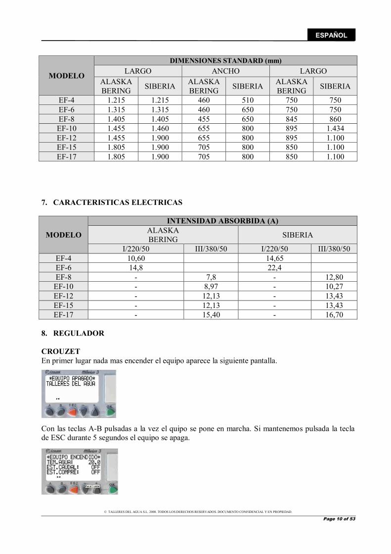
MODELO
DIMENSIONES STANDARD (mm) LARGO ANCHO LARGO
ALASKA BERING SIBERIA ALASKA
BERING SIBERIA ALASKA BERING SIBERIA
EF-4 1.215 1.215 460 510 750 750 EF-6 1.315 1.315 460 650 750 750 EF-8 1.405 1.405 455 650 845 860 EF-10 1.455 1.460 655 800 895 1.434 EF-12 1.455 1.900 655 800 895 1.100 EF-15 1.805 1.900 705 800 850 1.100 EF-17 1.805 1.900 705 800 850 1.100
7. CARACTERISTICAS ELECTRICAS
MODELO
INTENSIDAD ABSORBIDA (A) ALASKA BERING SIBERIA
I/220/50 III/380/50 I/220/50 III/380/50 EF-4 10,60 14,65 EF-6 14,8 22,4 EF-8 - 7,8 - 12,80
EF-10 - 8,97 - 10,27 EF-12 - 12,13 - 13,43 EF-15 - 12,13 - 13,43 EF-17 - 15,40 - 16,70
8. REGULADOR CROUZET En primer lugar nada mas encender el equipo aparece la siguiente pantalla.
Con las teclas A-B pulsadas a la vez el quipo se pone en marcha. Si mantenemos pulsada la tecla de ESC durante 5 segundos el equipo se apaga.
© TALLERES DEL AGUA S.L. 2008. TODOS LOS DERECHOS RESERVADOS. DOCUMENTO CONFIDENCIAL Y EN PROPIEDAD.
Page 11 of 53
ESPAÑOL
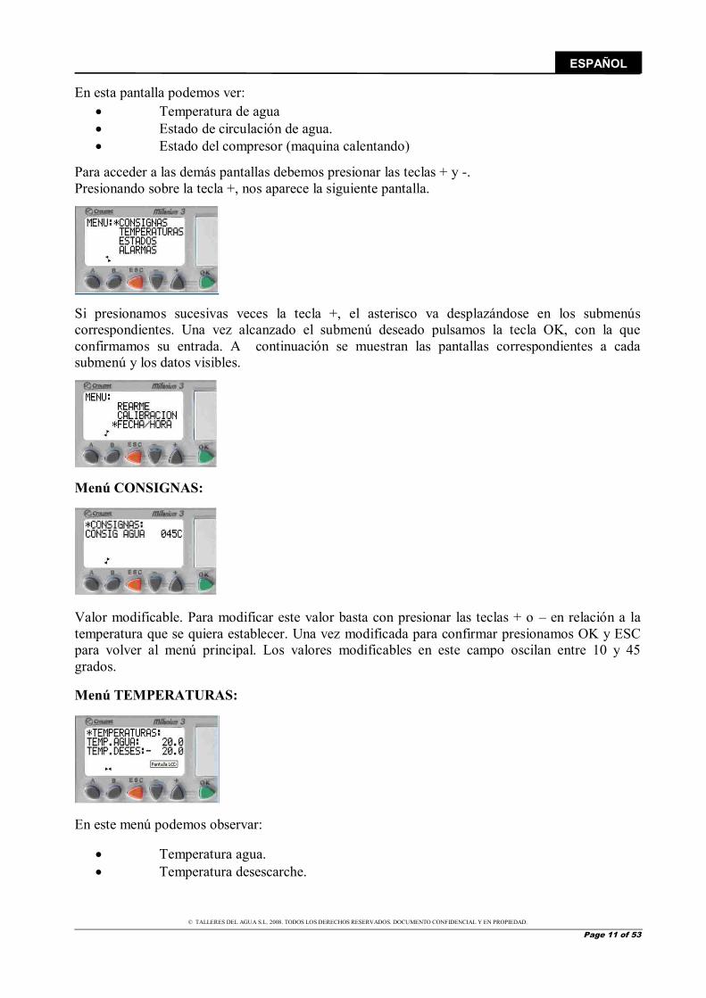
En esta pantalla podemos ver:
Temperatura de agua Estado de circulación de agua. Estado del compresor (maquina calentando)
Para acceder a las demás pantallas debemos presionar las teclas + y -. Presionando sobre la tecla +, nos aparece la siguiente pantalla.
Si presionamos sucesivas veces la tecla +, el asterisco va desplazándose en los submenús correspondientes. Una vez alcanzado el submenú deseado pulsamos la tecla OK, con la que confirmamos su entrada. A continuación se muestran las pantallas correspondientes a cada submenú y los datos visibles.
Menú CONSIGNAS:
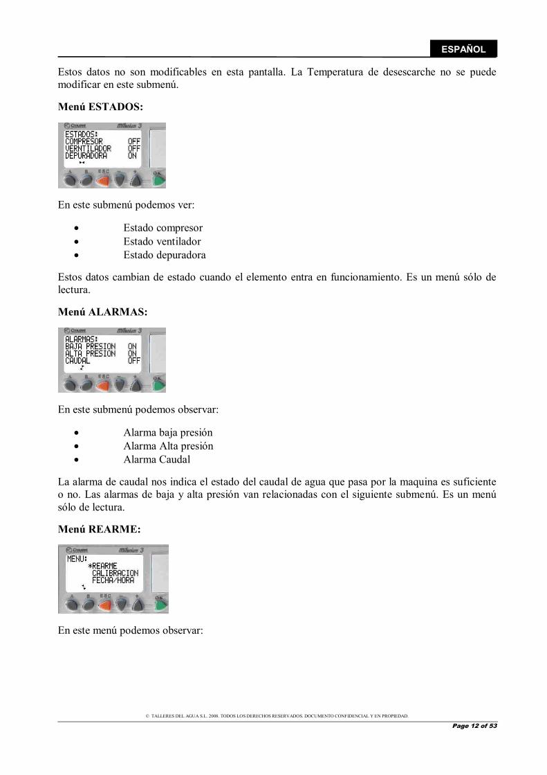
Valor modificable. Para modificar este valor basta con presionar las teclas + o – en relación a la temperatura que se quiera establecer. Una vez modificada para confirmar presionamos OK y ESC para volver al menú principal. Los valores modificables en este campo oscilan entre 10 y 45 grados. Menú TEMPERATURAS:
En este menú podemos observar:
Temperatura agua. Temperatura desescarche.
© TALLERES DEL AGUA S.L. 2008. TODOS LOS DERECHOS RESERVADOS. DOCUMENTO CONFIDENCIAL Y EN PROPIEDAD.
Page 12 of 53
ESPAÑOL
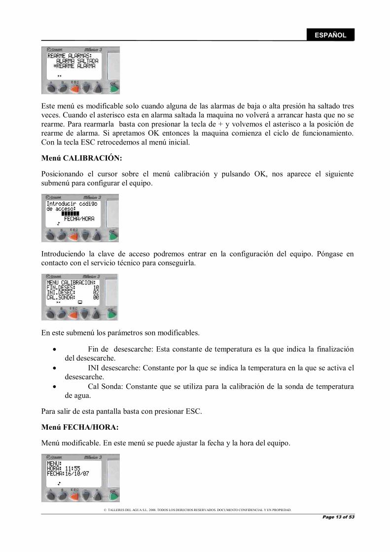
Estos datos no son modificables en esta pantalla. La Temperatura de desescarche no se puede modificar en este submenú. Menú ESTADOS:
En este submenú podemos ver:
Estado compresor Estado ventilador Estado depuradora
Estos datos cambian de estado cuando el elemento entra en funcionamiento. Es un menú sólo de lectura. Menú ALARMAS:
En este submenú podemos observar:
Alarma baja presión Alarma Alta presión Alarma Caudal
La alarma de caudal nos indica el estado del caudal de agua que pasa por la maquina es suficiente o no. Las alarmas de baja y alta presión van relacionadas con el siguiente submenú. Es un menú sólo de lectura. Menú REARME:
En este menú podemos observar:
© TALLERES DEL AGUA S.L. 2008. TODOS LOS DERECHOS RESERVADOS. DOCUMENTO CONFIDENCIAL Y EN PROPIEDAD.
Page 13 of 53
ESPAÑOL
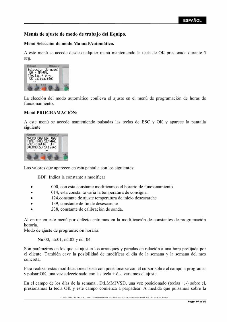
Este menú es modificable solo cuando alguna de las alarmas de baja o alta presión ha saltado tres veces. Cuando el asterisco esta en alarma saltada la maquina no volverá a arrancar hasta que no se rearme. Para rearmarla basta con presionar la tecla de + y volvemos el asterisco a la posición de rearme de alarma. Si apretamos OK entonces la maquina comienza el ciclo de funcionamiento. Con la tecla ESC retrocedemos al menú inicial. Menú CALIBRACIÓN: Posicionando el cursor sobre el menú calibración y pulsando OK, nos aparece el siguiente submenú para configurar el equipo.
Introduciendo la clave de acceso podremos entrar en la configuración del equipo. Póngase en contacto con el servicio técnico para conseguirla.
En este submenú los parámetros son modificables.
Fin de desescarche: Esta constante de temperatura es la que indica la finalización del desescarche.
INI desescarche: Constante por la que se indica la temperatura en la que se activa el desescarche.
Cal Sonda: Constante que se utiliza para la calibración de la sonda de temperatura de agua.
Para salir de esta pantalla basta con presionar ESC. Menú FECHA/HORA: Menú modificable. En este menú se puede ajustar la fecha y la hora del equipo.
© TALLERES DEL AGUA S.L. 2008. TODOS LOS DERECHOS RESERVADOS. DOCUMENTO CONFIDENCIAL Y EN PROPIEDAD.
Page 14 of 53
ESPAÑOL
Menús de ajuste de modo de trabajo del Equipo. Menú Selección de modo Manual/Automático. A este menú se accede desde cualquier menú manteniendo la tecla de OK presionada durante 5 seg.
La elección del modo automático conlleva el ajuste en el menú de programación de horas de funcionamiento. Menú PROGRAMACIÓN: A este menú se accede manteniendo pulsadas las teclas de ESC y OK y aparece la pantalla siguiente.
Los valores que aparecen en esta pantalla son los siguientes: BDF: Indica la constante a modificar
000, con esta constante modificamos el horario de funcionamiento 014, esta constante varia la temperatura de consigna. 124,constante de ajuste temperatura de inicio desescarche 139, constante de fin de desescarche 238, constante de calibración de sonda.
Al entrar en este menú por defecto entramos en la modificación de constantes de programación horaria. Modo de ajuste de programación horaria: Nú:00, nú:01, nú:02 y nú: 04 Son parámetros en los que se ajustan los arranques y paradas en relación a una hora prefijada por el cliente. También cave la posibilidad de modificar el día de la semana y la semana del mes concreta. Para realizar estas modificaciones basta con posicionarse con el cursor sobre el campo a programar y pulsar OK, una vez seleccionado con las tecla + ó -, variamos el ajuste. En el campo de los días de la semana., D:LMMJVSD, una vez posicionado (teclas +,-) sobre el, presionamos la tecla OK y este campo comienza a parpadear. A medida que pulsamos sobre la
© TALLERES DEL AGUA S.L. 2008. TODOS LOS DERECHOS RESERVADOS. DOCUMENTO CONFIDENCIAL Y EN PROPIEDAD.
Page 15 of 53
ESPAÑOL
tecla de OK el cursor va avanzando sobre los diferentes días de la semana y con las teclas +,- podemos anular el día de programación o activarlo según la programación deseada. Lo mismo ocurre con el campo de semanas del mes (S:12345). En este campo se pueden programar las semanas en que queremos que el equipo funcione.
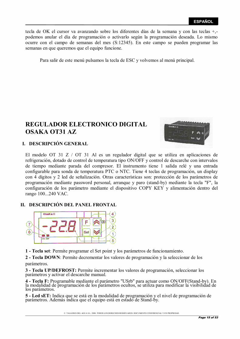
Para salir de este menú pulsamos la tecla de ESC y volvemos al menú principal. REGULADOR ELECTRONICO DIGITAL OSAKA OT31 AZ
I. DESCRIPCIÓN GENERAL El modelo OT 31 Z / OT 31 Al es un regulador digital que se utiliza en aplicaciones de refrigeración, dotado de control de temperatura tipo ON/OFF y control de descarche con intervalos de tiempo mediante parada del compresor. El instrumento tiene 1 salida relé y una entrada configurable para sonda de temperatura PTC o NTC. Tiene 4 teclas de programación, un display con 4 dígitos y 2 led de señalización. Otras características son: protección de los parámetros de programación mediante password personal, arranque y paro (stand-by) mediante la tecla "F", la configuración de los parámetro mediante el dispositivo COPY KEY y alimentación dentro del rango 100...240 VAC.
II. DESCRIPCIÓN DEL PANEL FRONTAL 1 - Tecla set: Permite programar el Set point y los parámetros de funcionamiento. 2 - Tecla DOWN: Permite decrementar los valores de programación y la seleccionar de los parámetros. 3 - Tecla UP/DEFROST: Permite incrementar los valores de programación, seleccionar los parámetros y activar el descarche manual. 4 - Tecla F: Programable mediante el parámetro "USrb" para actuar como ON/OFF(Stand-by). En la modalidad de programación de los parámetros ocultos, se utiliza para modificar la visibilidad de los parámetros. 5 - Led sET: Indica que se está en la modalidad de programación y el nivel de programación de parámetros. Además indica que el equipo está en estado de Stand-by.
© TALLERES DEL AGUA S.L. 2008. TODOS LOS DERECHOS RESERVADOS. DOCUMENTO CONFIDENCIAL Y EN PROPIEDAD.
Page 16 of 53
ESPAÑOL
6 - Led OUT: Indica el estado de la salida del compresor (o del dispositivo de control de la temperatura): on (encendido), off (apagado) o inhibida (en intermitencia) 7 - Led DEF: Indica que se está ejecutando el descarche.
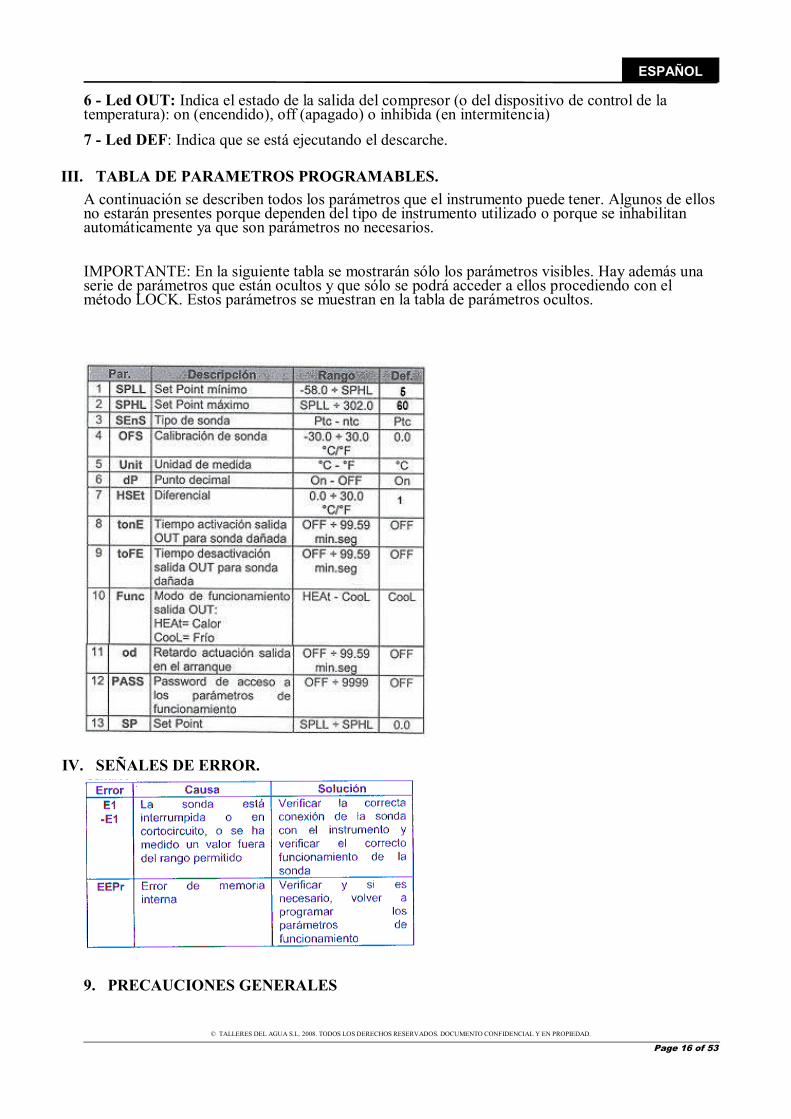
III. TABLA DE PARAMETROS PROGRAMABLES. A continuación se describen todos los parámetros que el instrumento puede tener. Algunos de ellos no estarán presentes porque dependen del tipo de instrumento utilizado o porque se inhabilitan automáticamente ya que son parámetros no necesarios. IMPORTANTE: En la siguiente tabla se mostrarán sólo los parámetros visibles. Hay además una serie de parámetros que están ocultos y que sólo se podrá acceder a ellos procediendo con el método LOCK. Estos parámetros se muestran en la tabla de parámetros ocultos.
IV. SEÑALES DE ERROR. 9. PRECAUCIONES GENERALES
© TALLERES DEL AGUA S.L. 2008. TODOS LOS DERECHOS RESERVADOS. DOCUMENTO CONFIDENCIAL Y EN PROPIEDAD.
Page 17 of 53
ESPAÑOL
¡ATENCIÓN! ES MUY IMPORTANTE NO INCLINAR EL EMBALAJE, PARA LO QUE ÉSTE SE DISEÑÓ
CONVENIENTEMENTE. SIEMPRE SE DEBERÁ MANTENER EN POSICIÓN VERTICAL. SI LA UNIDAD ESTÁ DAÑADA, O SI EL ENVIO NO ESTA COMPLETO, ANOTAR EN EL
ALBARÁN DE ENTREGA Y ENVIAR UNA RECLAMACIÓN INMEDIATA A LA COMPAÑÍA QUE REALIZÓ EL ENVÍO.
* Las operaciones de instalación, puesta en marcha y mantenimiento de la ENFRIADORA AIRE-AGUA COMPISA EF deben ser realizadas por personal cualificado. * No se debe de instalar estos equipos en entornos inflamables o explosivos. * Para cualquier operación de mantenimiento dentro de la máquina, se tendrá la precaución de desconectar la corriente eléctrica en el seccionador principal. * En las operaciones de mantenimiento es obligatorio el uso de equipos de protección o seguridad como gafas, guantes, etc. * Durante el funcionamiento de la máquina es habitual que las condensaciones que se producen en la evaporadora hagan que salga una cantidad de agua de la máquina que hay que evacuar. Las máquinas vienen provistas de un desagüe en un lateral de la carcasa, que siempre debe quedar libre de cualquier obstrucción. El agua de condensación no tiene que ser tratada de una forma especial.
10. COMPROBACIÓN DEL EMBALAJE ENFRIADORA AIRE-AGUA EF se presenta con un EMBALAJE RECICLABLE capaz de resistir unas duras condiciones de transporte. No obstante, durante la instalación de la misma se deberá efectuar una comprobación visual de cualquier desperfecto, de forma que se evite cualquier mal funcionamiento posterior.
TALLERES DEL AGUA no asumirá responsabilidad en ese caso.
En su interior encontrará los siguientes elementos: ENFRIADORA AIRE-AGUA EF Manual de Instalación. Garantía. 11. CONDICIONES DE TRABAJO Los parámetros físicos y químicos del agua deben de estar en los siguientes valores: PH 7,2 a 7,8 Cloro residual 1 a 2 ppm Alcalinidad 80-125 ppm Sólidos totales disueltos </=3000 miligramos/litro Dureza 200-300 ppm Condiciones ambientales nominales de funcionamiento son: Tª de entrada aire exterior 27º C Tª de entrada agua 24º C Humedad relativa 60% Hr
© TALLERES DEL AGUA S.L. 2008. TODOS LOS DERECHOS RESERVADOS. DOCUMENTO CONFIDENCIAL Y EN PROPIEDAD.
Page 18 of 53
ESPAÑOL
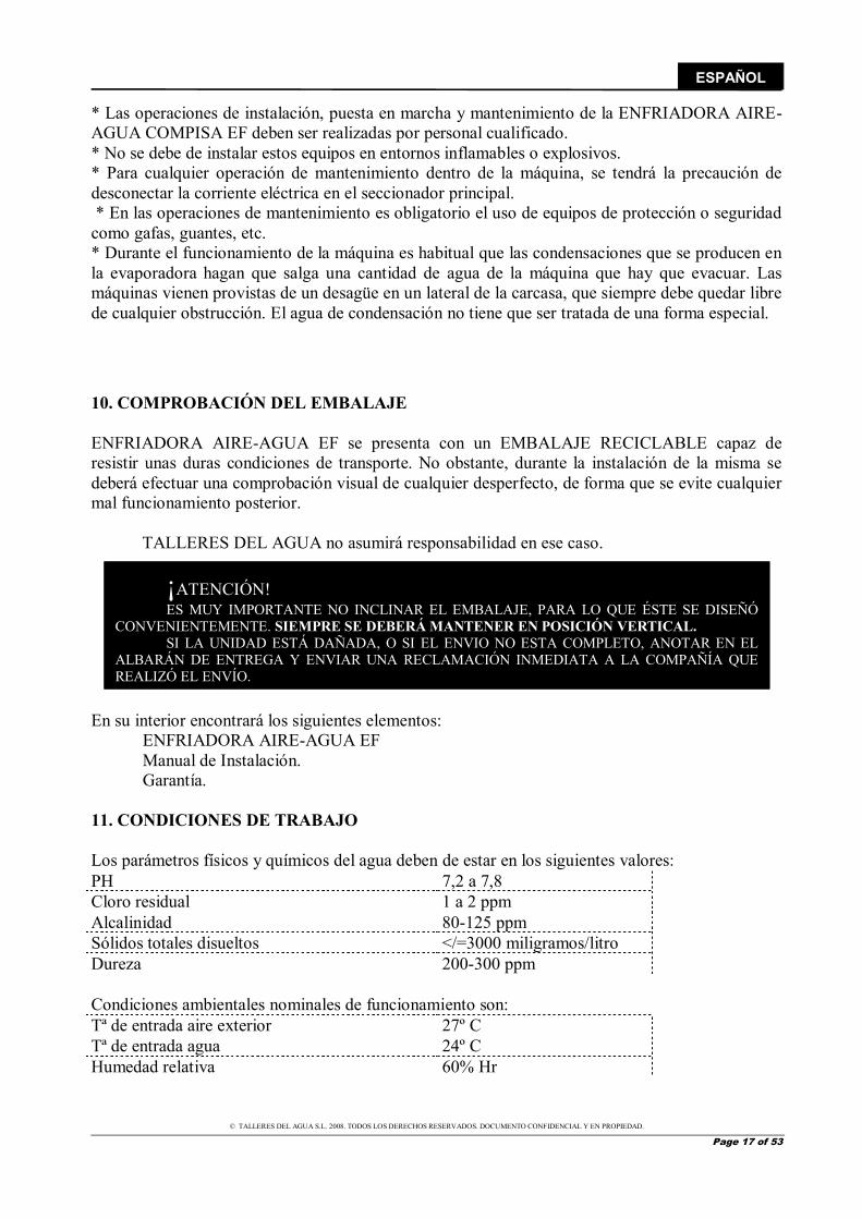
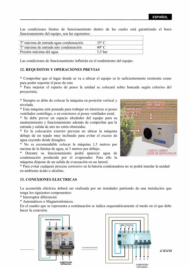
Las condiciones límites de funcionamiento dentro de las cuales está garantizado el buen funcionamiento del equipo, son las siguientes: Tª máxima de entrada agua condensación 35º C Tª máxima de entrada aire condensación 40º C Presión máxima del agua 3,5 bar Las condiciones de funcionamiento influirán en el rendimiento del equipo. 12. REQUISITOS Y OPERACIONES PREVIAS * Comprobar que el lugar donde se va a ubicar el equipo es lo suficientemente resistente como para poder soportar el peso de este. * Para mejorar el reparto de pesos la unidad se colocará sobre bancada según criterios del proyectista. * Siempre se debe de colocar la máquina en posición vertical y nivelada. * Esta máquina está pensada para trabajar en interiores si posee ventilador centrifugo, o en exteriores si posee ventilador axial. * Se debe prever un espacio alrededor del equipo para su mantenimiento y funcionamiento además de comprobar que la entrada y salida de aire no estén obstruidas. * En la colocación exterior prevean no ubicar la máquina debajo de un tejado muy inclinado para evitar el exceso de agua cayendo desde desagües. * No es recomendable colocar la máquina 1,5 metros por encima de la lámina de agua, ni 3 metros por debajo. * Durante su funcionamiento podrá aparecer agua de condensación producida por el evaporador. Para ello la máquina dispone de un salida de evacuación en un lateral. * Para evitar cualquier proceso corrosivo en la batería condensadora no se podrá instalar la unidad en ambiente ácido o alcalino. 13. CONEXIONES ELECTRICAS La acometida eléctrica deberá ser realizada por un instalador partiendo de una instalación que tenga los siguientes componentes: * Interruptor diferencial. * Automáticos o Magnetotérmicos. En el cuadro que se representa a continuación se indica esquemáticamente el modo en el que debe hacer la conexión.
© TALLERES DEL AGUA S.L. 2008. TODOS LOS DERECHOS RESERVADOS. DOCUMENTO CONFIDENCIAL Y EN PROPIEDAD.
Page 19 of 53
ESPAÑOL
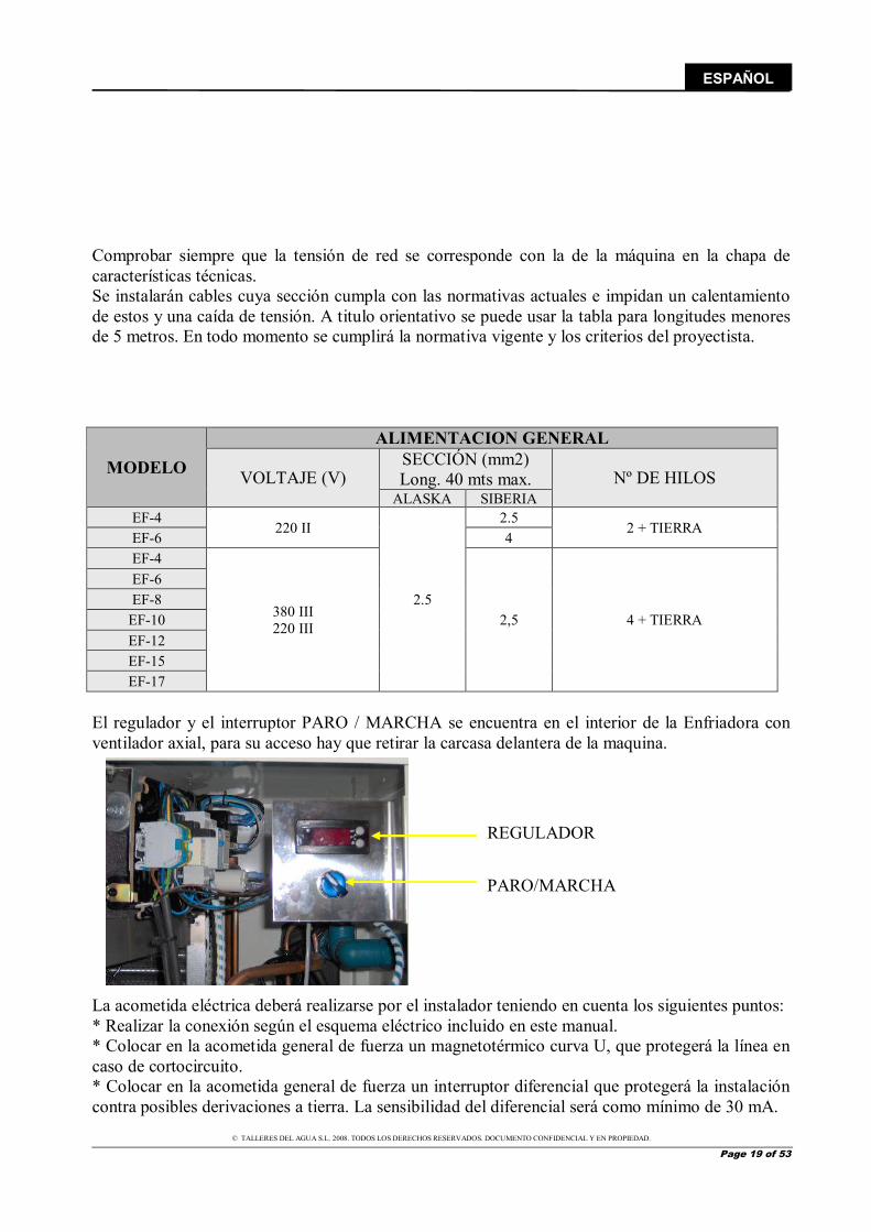
Comprobar siempre que la tensión de red se corresponde con la de la máquina en la chapa de características técnicas. Se instalarán cables cuya sección cumpla con las normativas actuales e impidan un calentamiento de estos y una caída de tensión. A titulo orientativo se puede usar la tabla para longitudes menores de 5 metros. En todo momento se cumplirá la normativa vigente y los criterios del proyectista.
MODELO
ALIMENTACION GENERAL
VOLTAJE (V) SECCIÓN (mm2) Long. 40 mts max. Nº DE HILOS
ALASKA SIBERIA EF-4
220 II
2.5
2.5 2 + TIERRA
EF-6 4 EF-4
380 III 220 III 2,5 4 + TIERRA
EF-6 EF-8
EF-10 EF-12 EF-15 EF-17
El regulador y el interruptor PARO / MARCHA se encuentra en el interior de la Enfriadora con ventilador axial, para su acceso hay que retirar la carcasa delantera de la maquina. La acometida eléctrica deberá realizarse por el instalador teniendo en cuenta los siguientes puntos: * Realizar la conexión según el esquema eléctrico incluido en este manual. * Colocar en la acometida general de fuerza un magnetotérmico curva U, que protegerá la línea en caso de cortocircuito. * Colocar en la acometida general de fuerza un interruptor diferencial que protegerá la instalación contra posibles derivaciones a tierra. La sensibilidad del diferencial será como mínimo de 30 mA.
REGULADOR
PARO/MARCHA
© TALLERES DEL AGUA S.L. 2008. TODOS LOS DERECHOS RESERVADOS. DOCUMENTO CONFIDENCIAL Y EN PROPIEDAD.
Page 20 of 53
ESPAÑOL
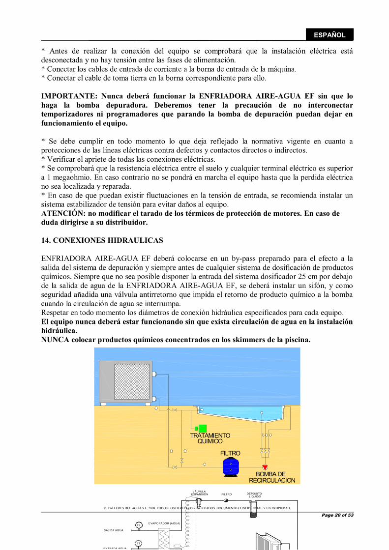
* Antes de realizar la conexión del equipo se comprobará que la instalación eléctrica está desconectada y no hay tensión entre las fases de alimentación. * Conectar los cables de entrada de corriente a la borna de entrada de la máquina. * Conectar el cable de toma tierra en la borna correspondiente para ello. IMPORTANTE: Nunca deberá funcionar la ENFRIADORA AIRE-AGUA EF sin que lo haga la bomba depuradora. Deberemos tener la precaución de no interconectar temporizadores ni programadores que parando la bomba de depuración puedan dejar en funcionamiento el equipo. * Se debe cumplir en todo momento lo que deja reflejado la normativa vigente en cuanto a protecciones de las líneas eléctricas contra defectos y contactos directos o indirectos. * Verificar el apriete de todas las conexiones eléctricas. * Se comprobará que la resistencia eléctrica entre el suelo y cualquier terminal eléctrico es superior a 1 megaohmio. En caso contrario no se pondrá en marcha el equipo hasta que la perdida eléctrica no sea localizada y reparada. * En caso de que puedan existir fluctuaciones en la tensión de entrada, se recomienda instalar un sistema estabilizador de tensión para evitar daños al equipo. ATENCIÓN: no modificar el tarado de los térmicos de protección de motores. En caso de duda dirigirse a su distribuidor. 14. CONEXIONES HIDRAULICAS ENFRIADORA AIRE-AGUA EF deberá colocarse en un by-pass preparado para el efecto a la salida del sistema de depuración y siempre antes de cualquier sistema de dosificación de productos químicos. Siempre que no sea posible disponer la entrada del sistema dosificador 25 cm por debajo de la salida de agua de la ENFRIADORA AIRE-AGUA EF, se deberá instalar un sifón, y como seguridad añadida una válvula antirretorno que impida el retorno de producto químico a la bomba cuando la circulación de agua se interrumpa. Respetar en todo momento los diámetros de conexión hidráulica especificados para cada equipo. El equipo nunca deberá estar funcionando sin que exista circulación de agua en la instalación hidráulica. NUNCA colocar productos químicos concentrados en los skimmers de la piscina.
LIQUIDODEPOSITOFILTRO
EVAPORADOR (AGUA)
SALIDA AGUA
EXPANSIÓNVÁLVULA
TT
FS
ENTRADA AGUA
TRATAMIENTO
FILTRO
BOMBA DE
QUIMICO
RECIRCULACION

© TALLERES DEL AGUA S.L. 2008. TODOS LOS DERECHOS RESERVADOS. DOCUMENTO CONFIDENCIAL Y EN PROPIEDAD.
Page 21 of 53
ESPAÑOL
Se deben instalar llaves de corte de paso total en cada uno de los elementos hidráulicos de la instalación y del equipo, de forma tal que permiten aislar cada uno de estos elementos en caso de necesidad (limpieza de filtros, reparaciones, sustituciones, etc.) sin obligar el vaciado del circuito. Se colocarán manguitos antivibratorios en la entrada y salida del equipo, para evitar vibraciones que produzcan fisuras o roturas en la instalación hidráulica. En la conexión del equipo a la red hidráulica no deberemos forzar los tubos de PVC. De esta forma evitaremos la rotura de los mismos. 15. OPERACIÓN DE PUESTA EN MARCHA * En una primera operación se debe de verificar las conexiones eléctricas, comprobar la tensión del equipo y la tensión de la red. * Verificar que las conexiones hidráulicas están correctamente realizadas. * Dar tensión al equipo conectando el interruptor general de fuerza externo a la unidad. Una vez conectada la maquina verificar las intensidades absorbidas por las fases. * Es importante destacar que los equipos llevan de serie resistencia de carter, el equipo deberá estar bajo tensión al menos 1 hora antes de su puesta en marcha, para que el aceite del compresor alcance su estado optimo y pueda lubricar los componentes del compresor. * En el caso de maquina trifásica, ésta lleva un relé de control de fase, que garantiza el correcto sentido de giro del compresor. Si el regulador indica que el compresor está en marcha y éste no lo hace, se debe intercambiar las fases. * Con el equipo en marcha comprobar las intensidades absorbidas por los motores eléctricos, comprobando que no sobrepasan los valores reflejados en la ficha técnica. * Comprobar que no existe desfase entre las corrientes de las distintas líneas salvo las debidas a los circuitos monofásicos. * Se deben de colocar manómetros de alta y baja presión en el circuito frigorífico y comprobar la carga de gas (apartado Carga de Gas). * Para realizar la parada del equipo desconectar el interruptor de marcha/paro. 16. MANTENIMIENTO PREVENTIVO

© TALLERES DEL AGUA S.L. 2008. TODOS LOS DERECHOS RESERVADOS. DOCUMENTO CONFIDENCIAL Y EN PROPIEDAD.
Page 22 of 53
ESPAÑOL
* Deberá llevarse un historial de cada elemento atendido en el mantenimiento así como las actividades o reparaciones realizadas. * Realizar cualquier operación de mantenimiento DESCONECTANDO PREVIAMENTE LA ALIMENTACIÓN DE ELECTRICIDAD A LA MÁQUINA. * Las superficies de las carcasas exteriores pueden limpiarse con un paño y un limpiador no agresivo. * La máquina ha sido concebida para trabajar en exteriores o interiores. * Es importante que la máquina se deposite en una apoyo estable y protegido de inundaciones. ATENCIÓN: cuando la instalación vaya a estar parada durante largos períodos de tiempo, se aconseja retirar el equipo de la instalación o bien ventilar periódicamente la sala donde esté ubicado. Esto es debido al ambiente húmedo y clorado al que se ven expuestos los equipos, lo cual provoca el deterioro acelerado de los componentes electrónicos del mismo. La garantía no cubre aquellos casos en que el producto quede dañado por exposiciones prolongadas a un ambiente húmedo y clorado. Aspectos a tener en cuenta: BATERIA DE INTERCAMBIO TERMICO: La batería condensadora debe de estar libre de obstáculos o polvo excesivo que impidan que el aire circula apropiadamente a través de la misma. Para efectuar su limpieza, utilice agua con poca presión y detergentes no abrasivos o específicos para ello. COMPRESOR: Se debe de comprobar el aceite del compresor en los modelos de maquinas que poseen visor de aceite. Comprobar que la resistencia de carter funciona correctamente. EVAPORADOR: Instalar los dosificadores de productos químicos “aguas abajo” de la ENFRIADORA AIRE-AGUA EF, a una altura inferior a la de la enfriadora, y siempre lo más lejos posible de la misma. Nunca en la aspiración de la bomba de depuración pues deterioraría el evaporador. VENTILADOR: Comprobar anualmente los caudales del ventilador. Limpiar la suciedad de los alabes del ventilador así como la rejilla de protección. CUADRO ELÉCTRICO: Verificar todas las conexiones eléctricas. Comprobar que no exista sobrecalentamiento en los terminales eléctricos. Verificar que los sistemas de protección funcionan correctamente. Verificar que el termostato o mando principal funcionan correctamente contrastando su lectura con un termómetro de mercurio (calibración de sonda). 17. AVERIAS, SUS CAUSAS Y SOLUCIONES
© TALLERES DEL AGUA S.L. 2008. TODOS LOS DERECHOS RESERVADOS. DOCUMENTO CONFIDENCIAL Y EN PROPIEDAD.
Page 23 of 53
ESPAÑOL
Las circunstancias por las que su ENFRIADORA AIRE-AGUA EF podría no funcionar se detallan a continuación: EL EQUIPO NO SE PONE EN MARCHA: Interruptor de maniobra abierto: Comprobar que no hay ningún cortocircuito en el cuadro de maniobra, reparar el posible cortocircuito. La bobina del contactor no se activa: Comprobar que no está quemada en cuyo caso sustituir. Comprobar los enclavamientos que activan dicha bobina. Térmico abierto: Comprobar el voltaje de la línea. Comprobar que las condiciones de trabajo son las correctas. Excesivo consumo del compresor. Cortocircuito en la línea del compresor. Presostato de baja abierto: Comprobar el funcionamiento de este, sustituyéndolo si fuera necesario. Comprobar el correcto funcionamiento del ventilador. Comprobar la carga de gas del equipo (perdida de refrigerante, equipo con fugas) para solucionar esto ver apartado carga de gas. Comprobar que hay buena circulación de aire en la batería de intercambio. Comprobar que no hay obstrucciones en el circuito frigorífico eliminándola si ocurriera esto. Comprobar el correcto funcionamiento de la válvula Termostática, comprobando que el bulbo no ha perdido gas y que la toma de presión no está obstruida, sustituir en caso necesario. Presostato de alta abierto: Comprobar el funcionamiento de este, sustituyéndolo si fuera necesario. Comprobar la carga de gas del equipo (exceso de refrigerante) para solucionar esto ver apartado carga de gas. Comprobar que no hay obstrucciones en el circuito frigorífico eliminándola si ocurriera esto. Comprobar que hay una buena circulación de agua por el condensador, verificando que no hay obstrucciones en el circuito hidráulico, que las llaves de corte están abiertas y que la bomba de depuración funciona correctamente (sustituir si fuera necesario). Alarma de falta de caudal: Comprobar el correcto funcionamiento de la bomba depuradora (puede que no de el caudal necesario). El filtro de la bomba depuradora esta sucio, en cuyo caso proceda a su limpieza. Las llaves de By-Pass están cerradas o no lo suficientemente abiertas, proceda a su revisión. La bomba no está depurando, revise el estado del reloj horario y el modo de depuración. El flujostato está averiado (avise al servicio técnico). Ciclo de desescarche: Las condiciones de aire ambiente no son adecuadas. La máquina no opera en estas condiciones, en este caso se recomienda desconectar la máquina. NIVEL DE ACEITE BAJO: Carga inicial de aceite bajo: Completar hasta el nivel necesario. Manchas de aceite en el equipo: Comprobar fugas en el circuito frigorífico reparándolas, verificar que las válvulas de alta y baja están bien apretadas, en caso de avería sustituirlas. EL EQUIPO FUNCIONA EN CICLOS DEMASIADO CORTOS: Presostato de baja se abre y se vuelve a cerrar: Verificar los apartados del punto anterior “presostato de baja abierto”. Contacto intermitente en el control de la máquina: Reparar o reemplazar el fallo del control eléctrico. Comprobar la sonda de temperatura. Comprobar que el equipo no es demasiado grande para la instalación. EL EQUIPO FUNCIONA CONTINUAMENTE:
© TALLERES DEL AGUA S.L. 2008. TODOS LOS DERECHOS RESERVADOS. DOCUMENTO CONFIDENCIAL Y EN PROPIEDAD.
Page 24 of 53
ESPAÑOL
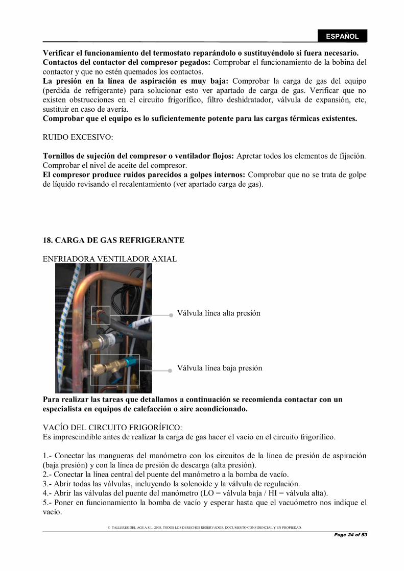
Verificar el funcionamiento del termostato reparándolo o sustituyéndolo si fuera necesario. Contactos del contactor del compresor pegados: Comprobar el funcionamiento de la bobina del contactor y que no estén quemados los contactos. La presión en la línea de aspiración es muy baja: Comprobar la carga de gas del equipo (perdida de refrigerante) para solucionar esto ver apartado de carga de gas. Verificar que no existen obstrucciones en el circuito frigorífico, filtro deshidratador, válvula de expansión, etc, sustituir en caso de avería. Comprobar que el equipo es lo suficientemente potente para las cargas térmicas existentes. RUIDO EXCESIVO: Tornillos de sujeción del compresor o ventilador flojos: Apretar todos los elementos de fijación. Comprobar el nivel de aceite del compresor. El compresor produce ruidos parecidos a golpes internos: Comprobar que no se trata de golpe de líquido revisando el recalentamiento (ver apartado carga de gas). 18. CARGA DE GAS REFRIGERANTE ENFRIADORA VENTILADOR AXIAL Para realizar las tareas que detallamos a continuación se recomienda contactar con un especialista en equipos de calefacción o aire acondicionado. VACÍO DEL CIRCUITO FRIGORÍFICO: Es imprescindible antes de realizar la carga de gas hacer el vacío en el circuito frigorífico. 1.- Conectar las mangueras del manómetro con los circuitos de la línea de presión de aspiración (baja presión) y con la línea de presión de descarga (alta presión). 2.- Conectar la línea central del puente del manómetro a la bomba de vacío. 3.- Abrir todas las válvulas, incluyendo la solenoide y la válvula de regulación. 4.- Abrir las válvulas del puente del manómetro (LO = válvula baja / HI = válvula alta). 5.- Poner en funcionamiento la bomba de vacío y esperar hasta que el vacuómetro nos indique el vacío.
Válvula línea alta presión
Válvula línea baja presión
© TALLERES DEL AGUA S.L. 2008. TODOS LOS DERECHOS RESERVADOS. DOCUMENTO CONFIDENCIAL Y EN PROPIEDAD.
Page 25 of 53
ESPAÑOL
6.- Cerrar todas las válvulas o llaves y desconectar la bomba de vacío. CARGA CON REFRIGERANTE GASEOSO: El equipo emplea refrigerante R-407-C, que es una mezcla de 3 gases diferentes, que se comportan de forma distinta. Es por esto que hay que tomar liquido de la botella de refrigerante e introducirlo en el circuito de baja presión a través de un cargador (sistema de expansión). Después de haber puesto el circuito frigorífico bajo vacío, después de haber instalado el cargador y haber conectado las tuberías flexibles de los manómetros a los circuitos de alta y baja presión, realizaremos la carga de gas. 1.- Conectar la línea central del puente del manómetro a la botella de R-407 por la llave de líquido. 2.- Abrir la llave de botella y purgar el trozo de tubería. 3.- Abrir la válvula de baja presión y la de alta presión. 4-. Presurizar la instalación hasta que se iguale su presión con la de la botella. 5.- Cerrar las válvulas del puente de manómetros. 6.- Poner en marcha la máquina. 7.- Abrir la válvula de baja hasta que la presión este 1 bar por encima del valor de disparo del presostato de baja. 8.- De vez en cuando, cerrar la válvula LO del puente de manómetros para leer la presión real de aspiración. 9.- Comprobar que la presión de descarga no aumenta por encima de la que se considera normal para las condiciones de trabajo. 10.- Cuando se haya introducido el peso correcto de refrigerante cerrar la válvula LO. 11.- Cuando la instalación esté trabajando según el diseño y condiciones de trabajo, cerrar la válvula de botella de carga, desconectar las mangueras de los obuses teniendo cuidado con la purga de gas. 12.- Colocar los tapones en las tomas de aspiración y descarga del compresor. DETECCIÓN DE FUGAS: Síntomas de pérdidas de gas. Las fugas provocan una disminución de la carga de refrigerante en el equipo. Una carga baja puede ser indicada por los siguientes síntomas:
◙ Temperatura de evaporación muy baja. Esto también puede ser debido a una obstrucción de la línea de líquido o a un mal funcionamiento de la válvula de expansión.
◙ Ciclos muy cortos de funcionamiento del compresor. ◙ Compresor sobrecalentado: La pérdida de gas provoca un caudal insuficiente de gas para
refrigerar el compresor. Esto puede provocar la activación del termostato interno del compresor.
◙ El compresor funciona constantemente, no hay refrigerante suficiente para obtener la potencia esperada, y como no se llega nunca a la temperatura de consigna, el equipo no para nunca.
En todo caso, es mejor no esperar a que aparezcan fugas e inspeccionar periódicamente el circuito. MÉTODOS DE BÚSQUEDA DE FUGAS DE GAS:
© TALLERES DEL AGUA S.L. 2008. TODOS LOS DERECHOS RESERVADOS. DOCUMENTO CONFIDENCIAL Y EN PROPIEDAD.
Page 26 of 53
ESPAÑOL
Existen en el mercado diferentes instrumentos de búsqueda de fugas, aunque no todos son suficientemente sensibles para ciertos refrigerantes. Es muy importante seleccionar un detector adecuado para el refrigerante que incorpora el equipo y que se cumplan las operaciones de mantenimiento. También se puede utilizar burbujas de jabón (spray de detergente líquido). Otros métodos como mecheros de antorcha halógena y aditivos en la instalación son también recomendables para la localización de fugas. EL GAS R-407-C: El R-407-C es un gas NO INFLAMABLE, no tiene punto de inflamación, no está sometido, por tanto, a la reglamentación de transporte de gases inflamables. El R-407-C no es irritante para la piel, los ojos y las mucosas y no produce sensibilidad cutánea. Tiene un bajo nivel de toxicidad tanto en exposición única como en exposiciones repetidas, no es mutágeno ni cancerígeno. El R-407-C es susceptible de ocasionar congelaciones en contacto del gas licuado con la piel, debido a su inmediata evaporación. Como todos los hidrocarburos, halogenados o no, el R-407-C es susceptible, a pesar de su bajo nivel de toxicidad, de ocasionar un estado preanestésico o anestésico general peligroso si se inhala una concentración muy elevada en medio cerrado. 19. GARANTIA Y CONDICIONES GENERALES La empresa fabricante garantiza la calidad del equipo especificado en la CARTA DE GARANTÏA que deberá de ir acompañando este manual de puesta en marcha y funcionamiento. La garantía de fabricación no cubre averías o daños causados por las siguientes circunstancias:
Instalación o uso inadecuado. Falta de aplicación de las instrucciones de limpieza y mantenimiento. Condiciones químicas inapropiadas. Operaciones realizadas por personal no autorizado. Daños causados por riegos inadecuados. Daños ocasionados por fenómenos naturales.
Esta maquina dispone de un gas frigorífico de estado liquido y de componentes eléctricos. Cuando la bomba de calor finalice su vida útil, deberá ser desmantelada por una empresa habilitada para ello o podrá llevarlo al sitio que destinen las diferentes entidades locales.
© TALLERES DEL AGUA S.L. 2008. TODOS LOS DERECHOS RESERVADOS. DOCUMENTO CONFIDENCIAL Y EN PROPIEDAD.
Page 27 of 53
ESPAÑOL
20. RECICLAJE DEL PRODUCTO Esta á ui a dispo e de u gas f igo ífi o de estado lí uido y de o po e tes elé t i os. Cua do la o a de alo fi ali e su vida útil, de e á se des a telada po u a e p esa ha ilitada pa a ello o pod á lleva lo al sitio ue desti a las dife e tes e tidades lo ales.
Co o jeto de edu i la a tidad de esiduos de apa atos elé t i os ele t ó i os, la pelig osidad de los o po e tes, fo e ta la eutiliza ió de los apa atos, la alo iza ió de sus esiduos dete i a u a gestió ade uada t ata do de ejo a la efi a ia de la p ote ió a ie tal, se esta le e u a se ie de o as apli a les a la fa i a ió del p odu to ot as elati as a la o e ta gestió a ie tal ua do se o ie ta e esiduo.
Así is o, se p ete de ejo a el o po ta ie to a ie tal de todos los age tes ue i te ie e e el i lo de ida de los apa atos elé t i os ele t ó i os, o o so los p odu to es, los dist i uido es, los usua ios e pa ti ula , el de a uellos age tes di e ta e te i pli ados e la gestió de los esiduos de i ados de estos apa atos.
A pa ti del de Agosto de ua do usted uie a dese ha este apa ato, tie e dos posi les siste as de de olu ió :
- Si ad uie e u o ue o ue sea de tipo e ui ale te o eali e las is as fu io es ue el ue dese ha, pod á e t ega lo, si oste, e el a to de la o p a al dist i uido . - O pod á lle a lo al sitio ue desti e las dife e tes e tidades lo ales.
Los apa atos a eti uetados o el sí olo de u o te edo de asu a o uedas ta hado , este sí olo es i di ati o de la e esa ia e ogida sele ti a dife e iada del esto de las asu as u a as.
Posi les efe tos so e el edio a ie te o la salud hu a a de las susta ias pelig osas ue pueda o te e .
PVC El plastifi a te ás usado e las apli a io es de PVC es el DEHP dietil-he il-ftalato . Los e sa os ealizados e di e sos la o a-to ios de uest a ue o p ese ta iesgo algu o pa a la salud hu a a e los i eles de o e t a ió utilizados e los a tí ulos a a ados, segú i fo es de la BUA e Ale a ia Cue po Aseso del Medio A ie te Rele a te de las susta ias E iste tes de la BGA Auto idad Ale a a de la Salud e t e ot os. Los esultados de di hos e sa os, u idos a los datos o te idos e los estudios de iodeg ada ió , o fi a ue el DEHP o puede se o side ado pelig oso pa a el edio a ie te. Todos los aditi os utilizados e las fo ula io es del PVC po lo ta to e las apli a io es ali e ta ías, está pe fe ta e te eguladas ta to a i el eu opeo o o español.
E Eu opa la Di e ti a Co u ita ia / /UE odifi ada poste io e te po la / /UE. A i el español ite os los Reales De etos / del de A il, el ual fue o fi ado po el / del de Ju io de ese is o año.
La ode a te ología apli ada desde ha e años e las pla tas de p odu ió del PVC, pe ite afi a ue éstas o p ese ta i gú pelig o pa a el edio a ie te, los a álisis de i lo de ida ACV de uest a ue el i pa to edioa ie tal del PVC es
e ui ale te o i luso ás fa o a le ue el de ot os ate iales.
© TALLERES DEL AGUA S.L. 2008. TODOS LOS DERECHOS RESERVADOS. DOCUMENTO CONFIDENCIAL Y EN PROPIEDAD.
Page 28 of 53
ESPAÑOL
TITANIO Efe tos so re la salud. El tita io ele e tal el dió ido de tita io tie e u i el ajo de to i idad. U a e posi ió e esi a e los hu a os al dió ido de tita io po i hala ió puede esulta e lige os a ios e los pul o es.
Efe tos de la so ree posi ió al pol o de tita io. La i hala ió del pol o puede ausa ti a tez dolo e el pe ho, tos, difi ultad pa a espi a . El o ta to o la piel los ojos puede p o o a i ita ió . Vías de e t ada: i hala ió , o ta to o la piel, o -ta to o los ojos.
Car i oge i idad. La age ia i te a io al pa a la i estiga ió del á e IARC ha i luido el dió ido de tita io e el g upo el age te o es lasifi a le o espe to a su a i oge i idad e hu a os .
Efe tos a ie tales. Baja to i idad. No se ha do u e tado efe tos a ie tales egati os del tita io CERTIFICADO DE GARANTÍA
. ASPECTOS GENERALES . De a ue do o estas disposi io es, el e dedo ga a tiza ue el p odu to o espo die te a esta ga a tía el p odu to o
p ese ta i gu a falta de o fo idad e el o e to de su e t ega. . El pe íodo de ga a tía pa a el p odu to es de dos años, se al ula á desde el o e to de e t ega al o p ado . . Si se p oduje a u a falta de o fo idad del P odu to el o p ado lo otifi ase al e dedo du a te el Pe íodo de Ga a tía, el e dedo de e á epa a o sustitui el P odu to a su p opio oste e el luga do de o side e opo tu o, sal o ue ello sea i posi le o
desp opo io ado. . Cua do o se pueda epa a i sustitui el P odu to, el o p ado pod á soli ita u a edu ió p opo io al del p e io o, si la falta de o fo idad es sufi ie te e te i po ta te, la esolu ió del o t ato de e ta. . Las pa tes sustituidas o epa adas e i tud de esta ga a tía o a plia á el plazo de la ga a tía del P odu to o igi al, si ie
dispo d á de su p opia ga a tía. . Pa a la efe ti idad de la p ese te ga a tía, el o p ado de e á a edita la fe ha de ad uisi ió e t ega del P odu to. . Cua do ha a t a s u ido ás de seis eses desde la e t ega del P odu to al o p ado éste alegue falta de o fo idad de
a uél, el o p ado de e á a edita el o ige la e iste ia del defe to alegado. . El p ese te Ce tifi ado de Ga a tía o li ita o p ejuzga los de e hos ue o espo da a los o su ido es e i tud de o as a io ales de a á te i pe ati o.
. CONDICIONES PARTICULARES . La p ese te ga a tía u e los p odu tos a ue ha e efe e ia este a ual. . El p ese te Ce tifi ado de Ga a tía se á de apli a ió ú i a e te e los países de la U ió Eu opea. . Pa a la efi a ia de esta ga a tía, el o p ado de e á segui est i ta e te las i di a io es del fa i a te i luidas e la
do u e ta ió ue a o paña al P odu to, ua do ésta esulte apli a le segú la ga a odelo del P odu to. . Cua do se espe ifi ue u ale da io pa a la sustitu ió , a te i ie to o li pieza de ie tas piezas o o po e tes del P odu to, la
Ga a tía sólo se á álida, ua do se ha a seguido di ho ale da io o e ta e te.
. LIMITACIONES . La p ese te ga a tía ú i a e te se á de apli a ió e a uellas e tas ealizadas a o su ido es, e te dié dose o su ido ,
a uella pe so a ue ad uie e el P odu to o fi es ue o e t a e el á ito de su a ti idad p ofesio al. . No se oto ga i gu a ga a tía espe to del o al desgaste po uso del P odu to. E ela ió o las piezas, o po e tes /o ate iales fu gi les o o su i les o o pilas, o illas et , se esta á a lo dispuesto e la do u e ta ió ue a o pañe al P odu to, e
su aso. . La ga a tía o u e a uellos asos e ue el P odu to: I ha a sido o jeto de u t ato i o e to; II ha a sido epa ado, a te ido
o a ipulado po pe so a o auto izada o III ha a sido epa ado o a te ido o piezas o o igi ales. Cua do la falta de o fo idad del P odu to sea o se ue ia de u a i o e ta i stala ió o puesta e a ha, la p ese te ga a tía sólo espo de á ua do di ha i stala ió o puesta e a ha esté i luida e el o t ato de o p a- e ta del P odu to ha a sido ealizada
po el e dedo o ajo su espo sa ilidad.
© TALLERES DEL AGUA S.L. 2008. TODOS LOS DERECHOS RESERVADOS. DOCUMENTO CONFIDENCIAL Y EN PROPIEDAD.
Page 29 of 53
ESPAÑOL
PRODUCTOS: ENFRIADORA AIRE/AGUA DECLARACIÓN CE DE CONFORMIDAD
Directiva de seguridad de máquinas 2006/42/CE.
Directiva de compatibilidad electromagnética 2004/108/CE, y sus modificaciones. Directiva de equipos de baja tensión 2006/95/CE.
Directiva sobre el ruido producido por máquinas para uso exterior 2000/14/CE y su corrección con la Directiva 2005/88/CE. Directiva sobre restricciones a la utilización de determinadas sustancias peligrosas en aparatos eléctricos y electrónicos
2002/95/CE (RoHS). Directiva sobre residuos de aparatos eléctricos y electrónicos 2002/96/CE (RAEE).
Real Decreto 208/2005 sobre aparatos eléctricos y electrónicos y la gestión de sus residuos. Reglamento relativo al registro, la evaluación, la autorización y la restricción de las sustancias y preparados químicos CE Nº
1907/2006 (REACH).
Firma la presente declaración: Los Corrales de Buelna Enero 2018
Sr. Jose Manuel Aquilue. Chief Executive Officer of B-39390968
© TALLERES DEL AGUA S.L. 2008. TODOS LOS DERECHOS RESERVADOS. DOCUMENTO CONFIDENCIAL Y EN PROPIEDAD.
Page 30 of 53
ENGLISH
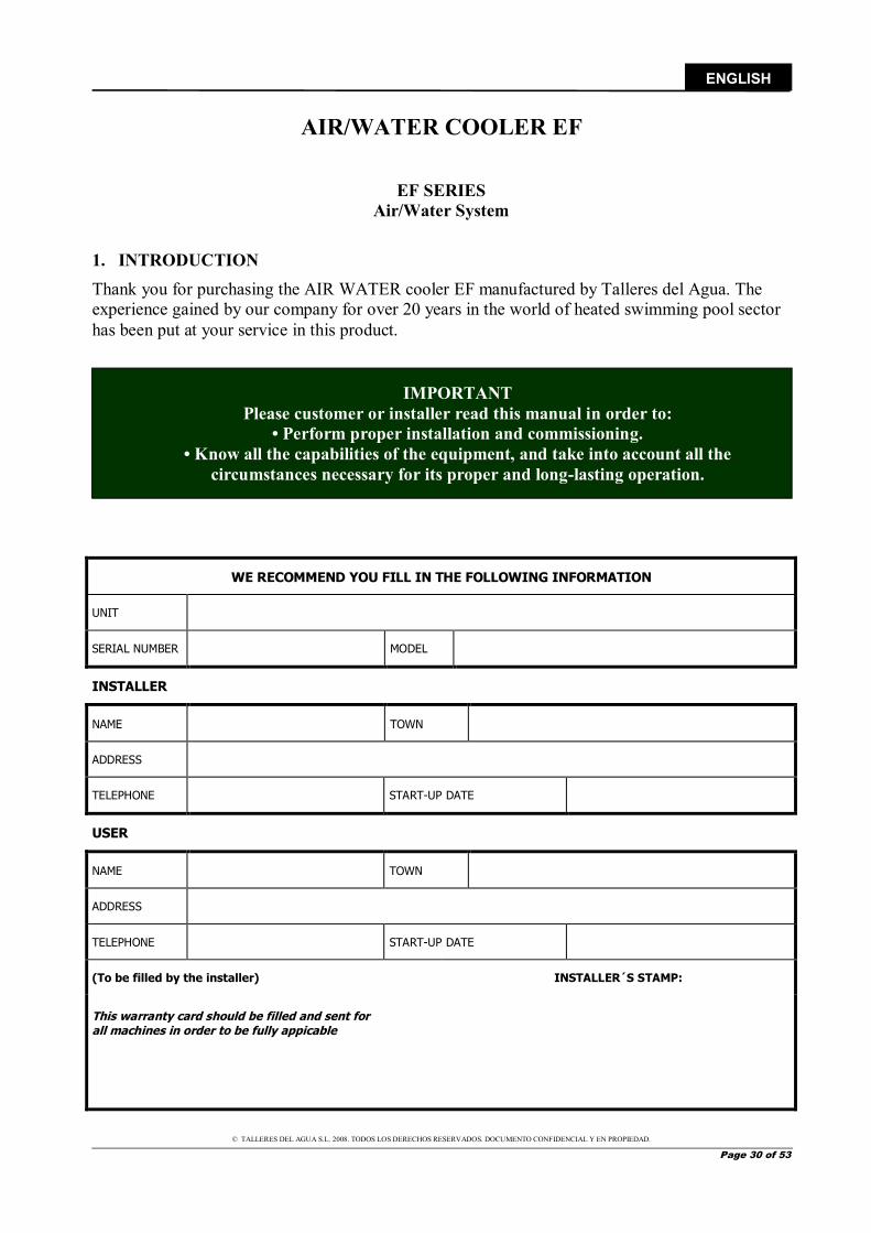
AIR/WATER COOLER EF
EF SERIES Air/Water System
1. INTRODUCTION Thank you for purchasing the AIR WATER cooler EF manufactured by Talleres del Agua. The experience gained by our company for over 20 years in the world of heated swimming pool sector has been put at your service in this product.
WE RECOMMEND YOU FILL IN THE FOLLOWING INFORMATION
UNIT
SERIAL NUMBER MODEL
INSTALLER
NAME TOWN
ADDRESS
TELEPHONE START-UP DATE
USER
NAME TOWN
ADDRESS
TELEPHONE START-UP DATE
(To be filled by the installer) INSTALLER´S STAMP:
This warranty card should be filled and sent for all machines in order to be fully appicable
IMPORTANT Please customer or installer read this manual in order to:
• Perform proper installation and commissioning. • Know all the capabilities of the equipment, and take into account all the
circumstances necessary for its proper and long-lasting operation.
© TALLERES DEL AGUA S.L. 2008. TODOS LOS DERECHOS RESERVADOS. DOCUMENTO CONFIDENCIAL Y EN PROPIEDAD.
Page 31 of 53
ENGLISH
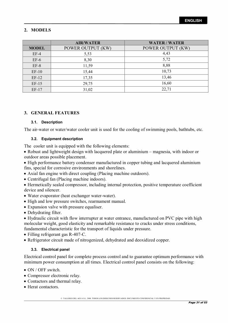
2. MODELS
3. GENERAL FEATURES
3.1. Description
The air-water or water/water cooler unit is used for the cooling of swimming pools, bathtubs, etc.
3.2. Equipment description
The cooler unit is equipped with the following elements: Robust and lightweight design with lacquered plate or aluminium – magnesia, with indoor or outdoor areas possible placement. High performance battery condenser manufactured in copper tubing and lacquered aluminium fins, special for corrosive environments and shorelines. Axial fan engine with direct coupling (Placing machine outdoors). Centrifugal fan (Placing machine indoors). Hermetically sealed compressor, including internal protection, positive temperature coefficient device and silencer. Water evaporator (heat exchanger water-water). High and low pressure switches, rearmament manual. Expansion valve with pressure equaliser. Dehydrating filter. Hydraulic circuit with flow interrupter at water entrance, manufactured on PVC pipe with high molecular weight, good elasticity and remarkable resistance to cracks under stress conditions, fundamental characteristic for the transport of liquids under pressure. Filling refrigerant gas R-407-C. Refrigerator circuit made of nitrogenized, dehydrated and deoxidized copper.
3.3. Electrical panel
Electrical control panel for complete process control and to guarantee optimum performance with minimum power consumption at all times. Electrical control panel consists on the following:
ON / OFF switch. Compressor electronic relay. Contactors and thermal relay. Herat contactors.
AIR/WATER WATER / WATER MODEL POWER OUTPUT (KW) POWER OUTPUT (KW)
EF-4 5,53 4,43 EF-6 8,30 5,72 EF-8 11,59 8,88 EF-10 15,44 10,73 EF-12 17,35 13,46 EF-15 29,75 16,60 EF-17 31,02 22,71
© TALLERES DEL AGUA S.L. 2008. TODOS LOS DERECHOS RESERVADOS. DOCUMENTO CONFIDENCIAL Y EN PROPIEDAD.
Page 32 of 53
ENGLISH
Controller.
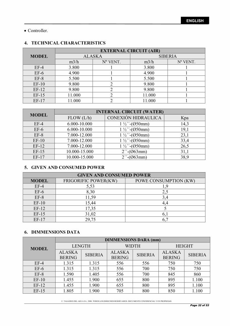
4. TECHNICAL CHARACTERISTICS
MODEL EXTERNAL CIRCUIT (AIR)
ALASKA SIBERIA m3/h Nº VENT. m3/h Nº VENT.
EF-4 3.800 1 3.800 1 EF-6 4.900 1 4.900 1 EF-8 5.500 1 5.500 1
EF-10 9.800 2 9.800 1 EF-12 9.800 2 9.800 1 EF-15 11.000 2 11.000 1 EF-17 11.000 2 11.000 1
MODEL INTERNAL CIRCUIT (WATER)
FLOW (L/h) CONEXIÓN HIDRAULICA Kpa EF-4 6.000-10.000 1 ½´´-(Ø50mm) 14,3 EF-6 6.000-10.000 1 ½´´-(Ø50mm) 19,1 EF-8 7.000-12.000 1 ½´´-(Ø50mm) 23,1 EF-10 7.000-12.000 1 ½´´-(Ø50mm) 33,4 EF-12 7.000-12.000 1 ½´´-(Ø50mm) 26,5 EF-15 10.000-15.000 2´´-(Ø63mm) 31,1 EF-17 10.000-15.000 2´´-(Ø63mm) 38,9
5. GIVEN AND CONSUMED POWER GIVEN AND CONSUMED POWER
MODEL FRIGORIFIC POWER(KW) POWE CONSUMPTION (KW) EF-4 5,53 1,9 EF-6 8,30 2,5 EF-8 11,59 3,4 EF-10 15,44 4,4 EF-12 17,35 5 EF-15 31,02 6,1 EF-17 29,75 6,7
6. DIMMENSIONS DATA
MODEL
DIMMENSIONS DARA (mm) LENGTH WIDTH HEIGHT
ALASKA BERING SIBERIA ALASKA
BERING SIBERIA ALASKA BERING SIBERIA
EF-4 1.315 1.315 556 556 750 750 EF-6 1.315 1.315 556 700 750 750 EF-8 1.590 1.405 556 700 845 860 EF-10 1.455 1.900 655 800 895 1.100 EF-12 1.455 1.900 655 800 895 1.100 EF-15 1.805 1.900 705 800 850 1.100
© TALLERES DEL AGUA S.L. 2008. TODOS LOS DERECHOS RESERVADOS. DOCUMENTO CONFIDENCIAL Y EN PROPIEDAD.
Page 33 of 53
ENGLISH
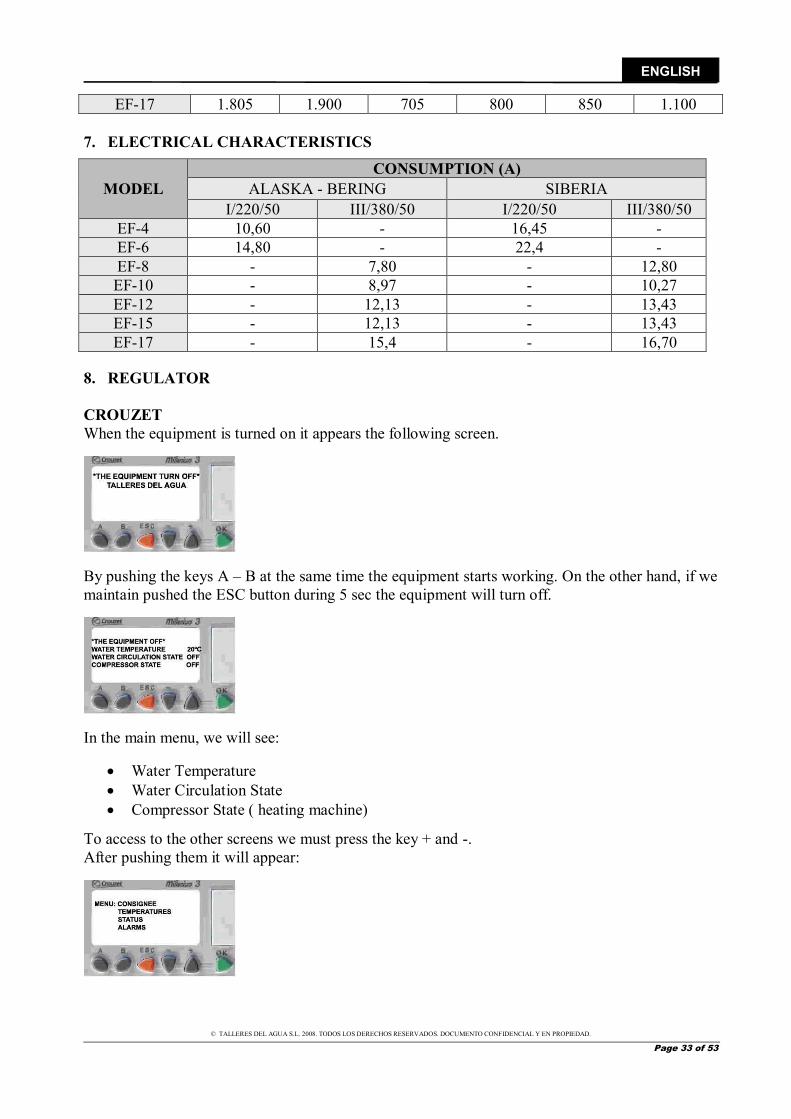
EF-17 1.805 1.900 705 800 850 1.100 7. ELECTRICAL CHARACTERISTICS
MODEL CONSUMPTION (A)
ALASKA - BERING SIBERIA I/220/50 III/380/50 I/220/50 III/380/50
EF-4 10,60 - 16,45 - EF-6 14,80 - 22,4 - EF-8 - 7,80 - 12,80 EF-10 - 8,97 - 10,27 EF-12 - 12,13 - 13,43 EF-15 - 12,13 - 13,43 EF-17 - 15,4 - 16,70
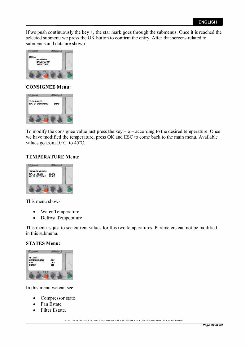
8. REGULATOR CROUZET When the equipment is turned on it appears the following screen.
By pushing the keys A – B at the same time the equipment starts working. On the other hand, if we maintain pushed the ESC button during 5 sec the equipment will turn off.
In the main menu, we will see:
Water Temperature Water Circulation State Compressor State ( heating machine)
To access to the other screens we must press the key + and -. After pushing them it will appear:
© TALLERES DEL AGUA S.L. 2008. TODOS LOS DERECHOS RESERVADOS. DOCUMENTO CONFIDENCIAL Y EN PROPIEDAD.
Page 34 of 53
ENGLISH
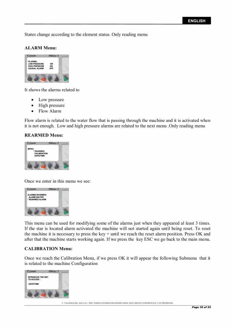
If we push continuously the key +, the star mark goes through the submenus. Once it is reached the selected submenu we press the OK button to confirm the entry. After that screens related to submenus and data are shown.
CONSIGNEE Menu:
To modify the consignee value just press the key + o – according to the desired temperature. Once we have modified the temperature, press OK and ESC to come back to the main menu. Available values go from 10ºC to 45ºC. TEMPERATURE Menu:
This menu shows:
Water Temperature Defrost Temperature
This menu is just to see current values for this two temperatures. Parameters can not be modified in this submenu. STATES Menu:
In this menu we can see:
Compressor state Fan Estate Filter Estate.
© TALLERES DEL AGUA S.L. 2008. TODOS LOS DERECHOS RESERVADOS. DOCUMENTO CONFIDENCIAL Y EN PROPIEDAD.
Page 35 of 53
ENGLISH
States change according to the element status. Only reading menu ALARM Menu:
It shows the alarms related to
Low pressure High pressure Flow Alarm
Flow alarm is related to the water flow that is passing through the machine and it is activated when it is not enough. Low and high pressure alarms are related to the next menu .Only reading menu REARMED Menu:
Once we enter in this menu we see:
This menu can be used for modifying some of the alarms just when they appeared al least 3 times. If the star is located alarm activated the machine will not started again until being reset. To reset the machine it is necessary to press the key + until we reach the reset alarm position. Press OK and after that the machine starts working again. If we press the key ESC we go back to the main menu. CALIBRATION Menu: Once we reach the Calibration Menu, if we press OK it will appear the following Submenu that it is related to the machine Configuration
© TALLERES DEL AGUA S.L. 2008. TODOS LOS DERECHOS RESERVADOS. DOCUMENTO CONFIDENCIAL Y EN PROPIEDAD.
Page 36 of 53
ENGLISH
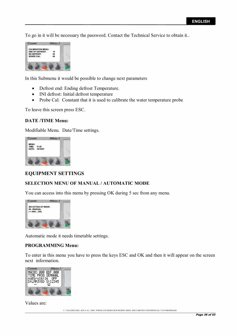
To go in it will be necessary the password. Contact the Technical Service to obtain it..
In this Submenu it would be possible to change next parameters
Defrost end: Ending defrost Temperature. INI defrost: Initial defrost temperature Probe Cal: Constant that it is used to calibrate the water temperature probe
To leave this screen press ESC. DATE /TIME Menu: Modifiable Menu. Date/Time settings.
EQUIPMENT SETTINGS SELECTION MENU OF MANUAL / AUTOMATIC MODE You can access into this menu by pressing OK during 5 sec from any menu.
Automatic mode it needs timetable settings. PROGRAMMING Menu: To enter in this menu you have to press the keys ESC and OK and then it will appear on the screen next information.
Values are:
© TALLERES DEL AGUA S.L. 2008. TODOS LOS DERECHOS RESERVADOS. DOCUMENTO CONFIDENCIAL Y EN PROPIEDAD.
Page 37 of 53
ENGLISH
BDF: Shows the constant to modify
000, with this constant we modify the working hours. 014, with this constant we vary the temperature of consignee. 124, starting defrost temperature constant. 139, ending defrost temperature. 238, calibration probe constant
By entering in this menu we automatically go into the timetable setting constants. Timetable settings:
Nº: 00, nº: 01 nº 02; nº 04 These are the parameters to set starts/stops according to the user’s settings. It is also possible to set the day of the week and the week of the month In order to make all these modifications you must reach the field that we want to program and then press OK. Once selected we can change values by pressing keys+ and – . Entering in the day of the week field , D: LMMJVSD, once selected thanks to keys + / -, we press OK and the field will light on discontinuously. This means we can choose the day of the week that we want to set. Press cancel to exit. The same happens with the months. With this function we can do all the time set that will fix the working periods.
To exit from this menu press the ESC and we will come back to the main Menu.
© TALLERES DEL AGUA S.L. 2008. TODOS LOS DERECHOS RESERVADOS. DOCUMENTO CONFIDENCIAL Y EN PROPIEDAD.
Page 38 of 53
ENGLISH
DIGITAL ELECTRONIC REGULATOR, OSAKA OT31 AZ
I. GENERAL DESCRIPTION
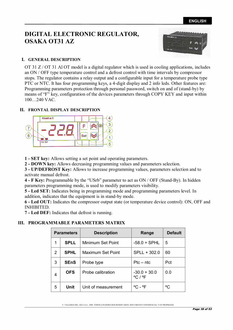
OT 31 Z / OT 31 Al OT model is a digital regulator which is used in cooling applications, includes an ON / OFF type temperature control and a defrost control with time intervals by compressor stops. The regulator contains a relay output and a configurable input for a temperature probe type PTC or NTC. It has four programming keys, a 4-digit display and 2 info leds. Other features are: Programming parameters protection through personal password, switch on and of (stand-by) by means of “F” key, configuration of the devices parameters through COPY KEY and input within 100…240 VAC.
II. FRONTAL DISPLAY DESCRIPTION
1 - SET key: Allows setting a set point and operating parameters. 2 - DOWN key: Allows decreasing programming values and parameters selection. 3 - UP/DEFROST Key: Allows to increase programming values, parameters selection and to activate manual defrost. 4 - F Key: Programmable by the “USrb” parameter to act as ON / OFF (Stand-By). In hidden parameters programming mode, is used to modify parameters visibility. 5 - Led SET: Indicates being in programming mode and programming parameters level. In addition, indicates that the equipment is in stand-by mode. 6 - Led OUT: Indicates the compressor output state (or temperature device control): ON, OFF and INHIBITED. 7 - Led DEF: Indicates that defrost is running.
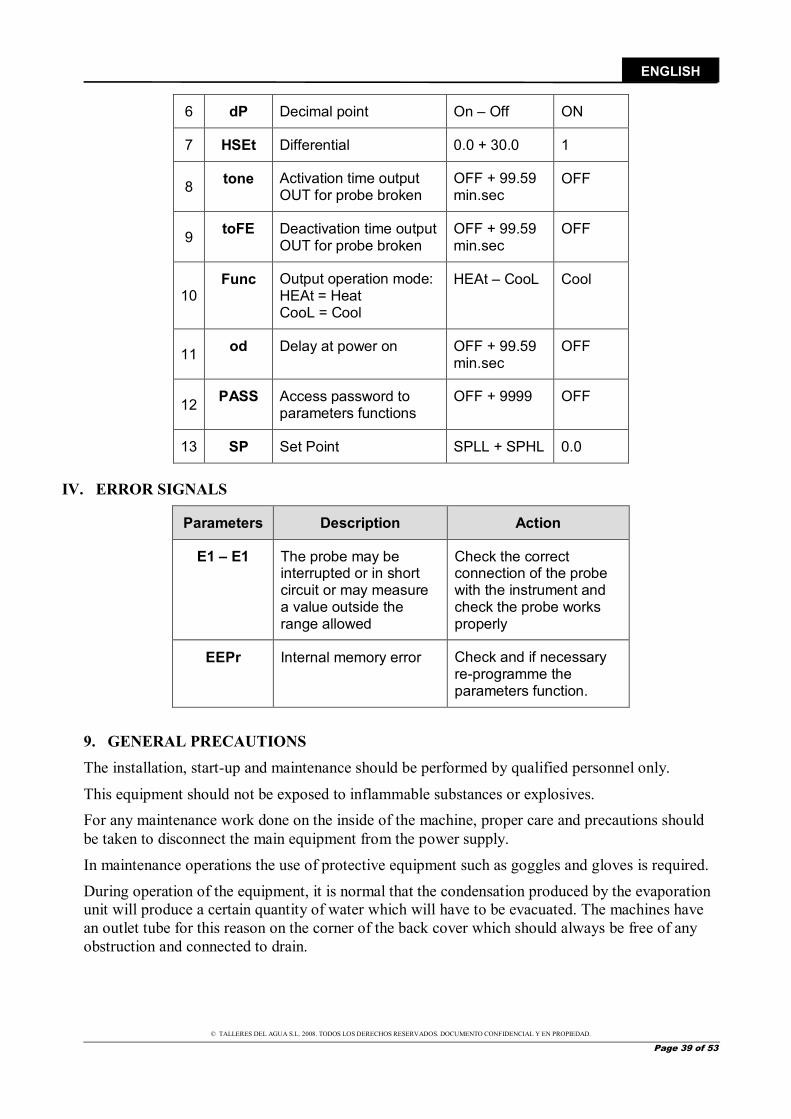
III. PROGRAMMABLE PARAMETERS MATRIX
Parameters Description Range Default
1 SPLL Minimum Set Point -58.0 + SPHL 5
2 SPHL Maximum Set Point SPLL + 302.0 60
3 SEnS Probe type Ptc – ntc Pct
4 OFS Probe calibration -30.0 + 30.0 ºC / ºF
0.0
5 Unit Unit of measurement ºC - ºF ºC
© TALLERES DEL AGUA S.L. 2008. TODOS LOS DERECHOS RESERVADOS. DOCUMENTO CONFIDENCIAL Y EN PROPIEDAD.
Page 39 of 53
ENGLISH
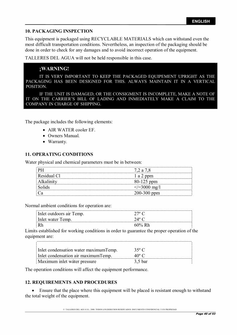
6 dP Decimal point On – Off ON
7 HSEt Differential 0.0 + 30.0 1
8 tone Activation time output OUT for probe broken
OFF + 99.59 min.sec
OFF
9 toFE Deactivation time output OUT for probe broken
OFF + 99.59 min.sec
OFF
10 Func Output operation mode:
HEAt = Heat CooL = Cool
HEAt – CooL Cool
11 od Delay at power on OFF + 99.59 min.sec
OFF
12 PASS Access password to parameters functions
OFF + 9999 OFF
13 SP Set Point SPLL + SPHL 0.0
IV. ERROR SIGNALS
Parameters Description Action
E1 – E1 The probe may be interrupted or in short circuit or may measure a value outside the range allowed
Check the correct connection of the probe with the instrument and check the probe works properly
EEPr Internal memory error Check and if necessary re-programme the parameters function.
9. GENERAL PRECAUTIONS The installation, start-up and maintenance should be performed by qualified personnel only.
This equipment should not be exposed to inflammable substances or explosives. For any maintenance work done on the inside of the machine, proper care and precautions should be taken to disconnect the main equipment from the power supply.
In maintenance operations the use of protective equipment such as goggles and gloves is required.
During operation of the equipment, it is normal that the condensation produced by the evaporation unit will produce a certain quantity of water which will have to be evacuated. The machines have an outlet tube for this reason on the corner of the back cover which should always be free of any obstruction and connected to drain.
© TALLERES DEL AGUA S.L. 2008. TODOS LOS DERECHOS RESERVADOS. DOCUMENTO CONFIDENCIAL Y EN PROPIEDAD.
Page 40 of 53
ENGLISH
10. PACKAGING INSPECTION This equipment is packaged using RECYCLABLE MATERIALS which can withstand even the most difficult transportation conditions. Nevertheless, an inspection of the packaging should be done in order to check for any damages and to avoid incorrect operation of the equipment.
TALLERES DEL AGUA will not be held responsible in this case.
¡WARNING! IT IS VERY IMPORTANT TO KEEP THE PACKAGED EQUIPEMENT UPRIGHT AS THE
PACKAGING HAS BEEN DESIGNED FOR THIS. ALWAYS MAINTAIN IT IN A VERTICAL POSITION.
IF THE UNIT IS DAMAGED, OR THE CONSIGMENT IS INCOMPLETE, MAKE A NOTE OF IT ON THE CARRIER’S BILL OF LADING AND INMEDIATELY MAKE A CLAIM TO THE COMPANY IN CHARGE OF SHIPPING.
The package includes the following elements:
AIR WATER cooler EF. Owners Manual. Warranty.
11. OPERATING CONDITIONS Water physical and chemical parameters must be in between:
PH 7,2 a 7,8 Residual Cl 1 a 2 ppm Alkalinity 80-125 ppm Solids </=3000 mg/l Ca 200-300 ppm
Normal ambient conditions for operation are:
Inlet outdoors air Temp. 27º C Inlet water Temp. 24º C Rh 60% Rh
Limits established for working conditions in order to guarantee the proper operation of the equipment are:
Inlet condensation water maximumTemp. 35º C Inlet condensation air maximumTemp. 40º C Maximum inlet wáter pressure 3,5 bar
The operation conditions will affect the equipment performance.
12. REQUIREMENTS AND PROCEDURES
Ensure that the place where this equipment will be placed is resistant enough to withstand the total weight of the equipment.
© TALLERES DEL AGUA S.L. 2008. TODOS LOS DERECHOS RESERVADOS. DOCUMENTO CONFIDENCIAL Y EN PROPIEDAD.
Page 41 of 53
ENGLISH
To improve equipment weight distribution, it will be placed on a bench following design criteria.
Always place the equipment upright and levelled. This equipment is designed to work indoors if equipped with a centrifugal fan or outdoors
if equipped with an axial fan. Enough free space should be left around equipment for its proper operation and possible
maintenance operations. In addition it will be verified that air in and outlets are not obstructed. Outdoors placement should not be done under roofs too inclined to avoid excessive water
drains from falling. It is not recommended to place the equipment 1.5 meters above the pool, or 3 meters
bellow. During equipment operation, water condensation may appear, produced by the evaporator.
For this reason the equipment have an outlet tube on side cover which should always be free of any obstruction and connected to drain.
To avoid any corrosive process in condenser battery, the equipment will not be placed in acid or alkaline environments.
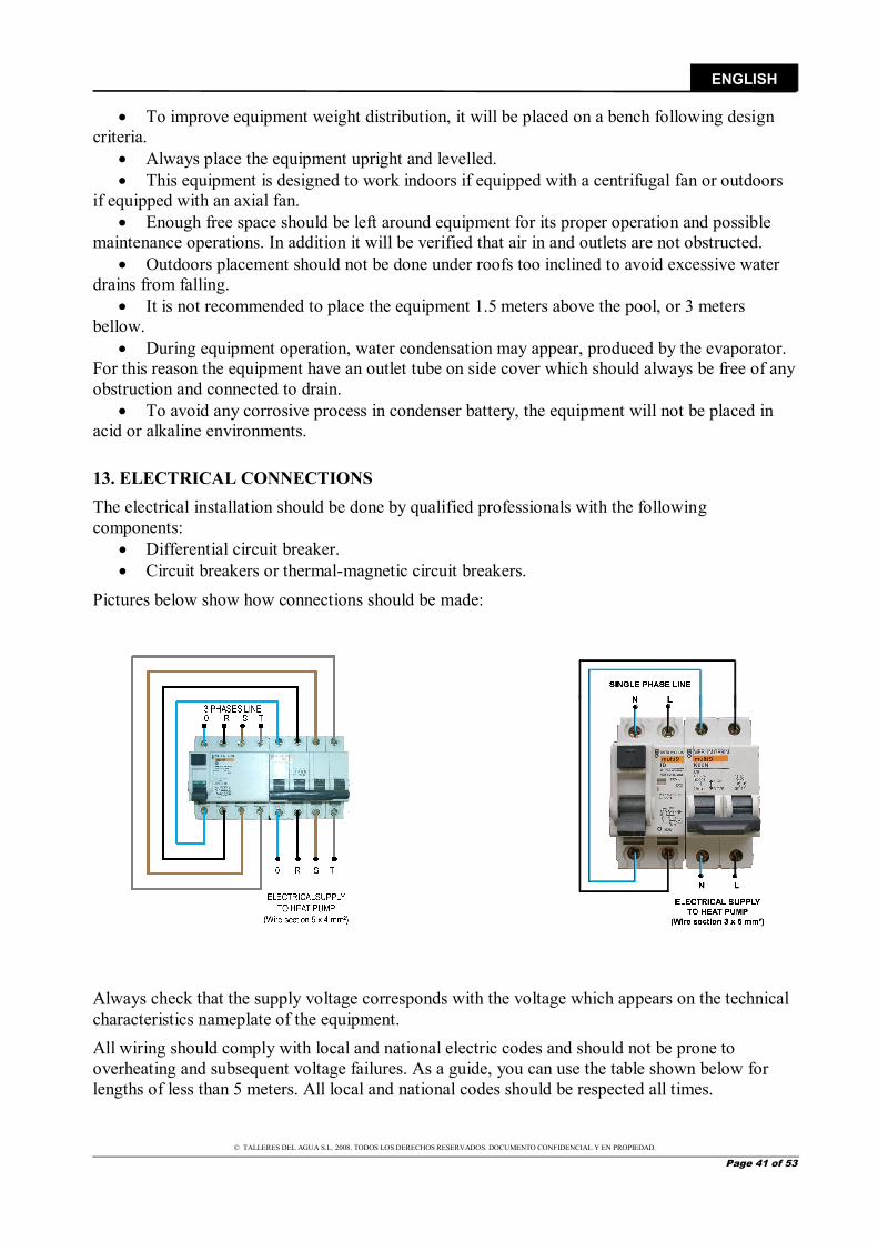
13. ELECTRICAL CONNECTIONS The electrical installation should be done by qualified professionals with the following components:
Differential circuit breaker. Circuit breakers or thermal-magnetic circuit breakers.
Pictures below show how connections should be made:
Always check that the supply voltage corresponds with the voltage which appears on the technical characteristics nameplate of the equipment. All wiring should comply with local and national electric codes and should not be prone to overheating and subsequent voltage failures. As a guide, you can use the table shown below for lengths of less than 5 meters. All local and national codes should be respected all times.

© TALLERES DEL AGUA S.L. 2008. TODOS LOS DERECHOS RESERVADOS. DOCUMENTO CONFIDENCIAL Y EN PROPIEDAD.
Page 42 of 53
ENGLISH
MODEL
GENERAL POWER
VOLTAGE (V) SECTION (mm2)
40 mts. max. Nº OF WIRES ALASKA SIBERIA
EF-4 220 II
2,5
2,5 2 + GROUND EF-6 4 EF-4
380 III 220 III 2,5 4 + GROUND
EF-6 EF-8
EF-10 EF-12 EF-15 EF-17
Regulator and ON / OFF switch are placed inside the cooler with axial fan; for access front cover of the equipment must be removed.
The electrical installation should be done by qualified professionals, keeping in mind the following points:
Perform electrical connections following present manual indications. Place a U-curve thermal-magnetic circuit breaker in the general power connection to protect the line in case of a short in the circuit. Place a differential circuit breaker in the general power connection to protect the equipment from possible ground problems. The differential breaker should be minimum 30mA. Before installing the connections are sure to disconnect the electricity so that the power supply is turned off. Connect the power supply wires to the machines input terminals. Connect the grounding wire to its corresponding terminal.
IMPORTANT: Cooler Air-Water EF shall never operate without the simultaneous operation of the purifier pump. Special careful should be taken at the time of interconnecting timers or programmers that may stop the purification pump, leaving the cooler running.
All local and national electric regulations concerning protection against defects in electric power lines should be respected at all times during installation. Verify the torque of all electrical connections.
REGULATOR
ON / OFF SWITCH
© TALLERES DEL AGUA S.L. 2008. TODOS LOS DERECHOS RESERVADOS. DOCUMENTO CONFIDENCIAL Y EN PROPIEDAD.
Page 43 of 53
ENGLISH
The electrical resistance between ground and any electrical terminal will be verified to be greater than 1 megaohm, if less, equipment shall not be powered on until power loss is located and repaired. In the event of power fluctuations in the input power supply, a power supply stabilising system is to be installed in order to prevent possible damages to the equipment.
ATTENTION: Do not change the git of the thermal protection engine. If in doubt, contact your dealer.
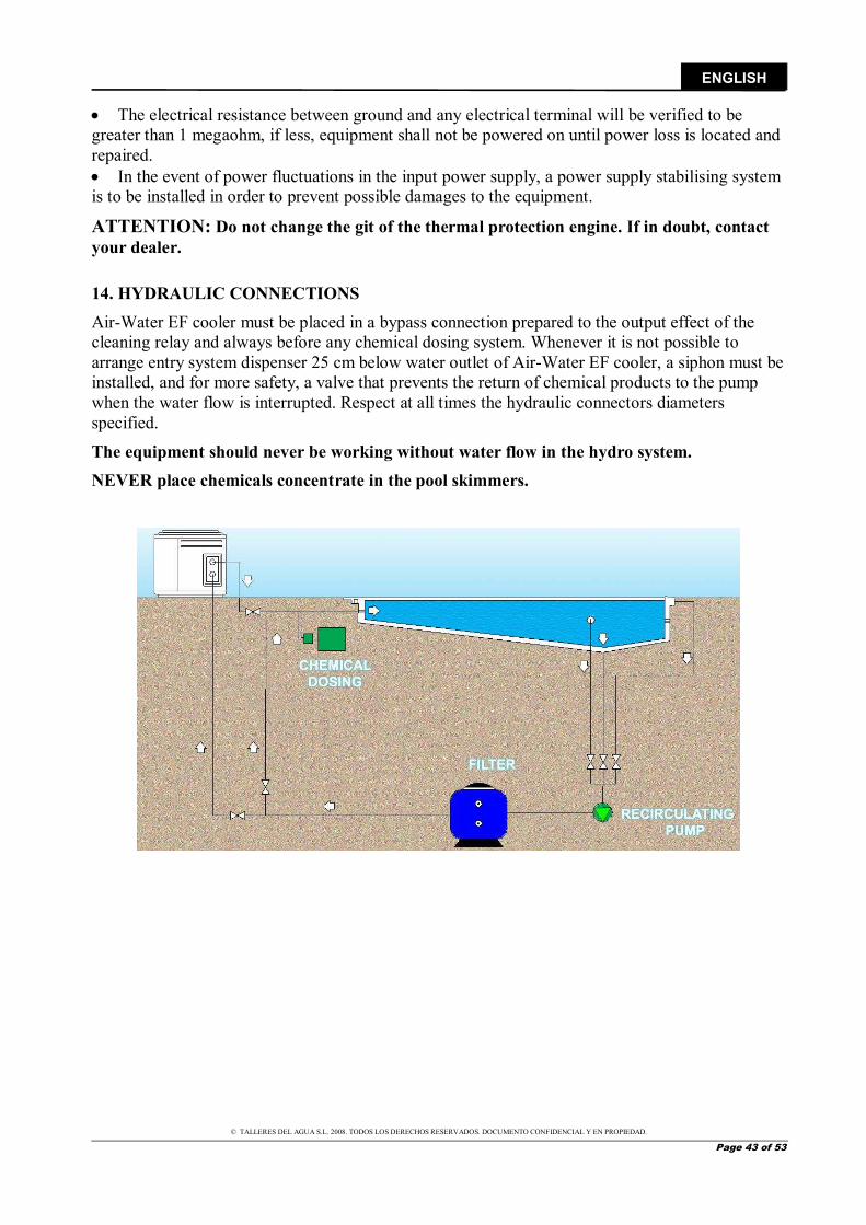
14. HYDRAULIC CONNECTIONS Air-Water EF cooler must be placed in a bypass connection prepared to the output effect of the cleaning relay and always before any chemical dosing system. Whenever it is not possible to arrange entry system dispenser 25 cm below water outlet of Air-Water EF cooler, a siphon must be installed, and for more safety, a valve that prevents the return of chemical products to the pump when the water flow is interrupted. Respect at all times the hydraulic connectors diameters specified.
The equipment should never be working without water flow in the hydro system. NEVER place chemicals concentrate in the pool skimmers.

© TALLERES DEL AGUA S.L. 2008. TODOS LOS DERECHOS RESERVADOS. DOCUMENTO CONFIDENCIAL Y EN PROPIEDAD.
Page 44 of 53
ENGLISH
A full-flow shut-off valve should be installed on each of the hydraulic elements in the equipment, so that each of these may be isolated if needed (for repairs, substitutions, etc.) without the need to drain the circuit.
Anti-vibration dampers should be installed in the inlet and outlet of the machine, in order to avoid vibrations which may cause cracks or breakage in the hydraulic connections.
In order to avoid possible breakage, do not force the PVC tubes connected to the water supply.
15. PROCEDURES AND START-UP When setting-up, the electrical connections, as well as the general power supply and voltage, should be verified.
Verify that the hydraulic connections are correct. Give power to the equipment by connecting the general power switch on the outside of the machine. Once the machine is connected, verify the intensity absorbed by the phases. It is important to comment that this equipment includes compressor casing resistance, so the equipment must be connected to main power at least 1 hour before the equipment is put in service so that the compressors oil reaches its optimum conditions and can lubricate components of the compressor. In the case of three-phase machine, equipment includes a relay phase control, which ensures the correct compressor rotation direction. If the regulator indicates that the compressor is running and it does not, then it is required to invert phases.
With the machine running, verify the intensities absorbed by the resistors and electric motors, making sure they do not exceed the limits mentioned in the technical specification sheet.
Make sure that there is no gap between the currents of the different phases except for those due to single phase circuits.
LIQUIDODEPOSITOFILTRO
EVAPORADOR (AGUA)
SALIDA AGUA
EXPANSIÓNVÁLVULA
BATERIA
OBUS
CARGADE
COMPRESOR
HPS
CONDENSADORA
TT
FS
ENTRADA AGUA
LPS
OBUS
CARGADE
OBUS
CARGADE
ASP.
DESC.
Water Input
Water Output
Evaporator (water)
Expansion valve Filter
Battery condenser
Compressor
© TALLERES DEL AGUA S.L. 2008. TODOS LOS DERECHOS RESERVADOS. DOCUMENTO CONFIDENCIAL Y EN PROPIEDAD.
Page 45 of 53
ENGLISH
High and low pressure switches should be installed in the cooling circuit and verify the refrigerant charge (Refrigerant Charge section).
To stop the equipment, disconnect switch on / off.
16. PREVENTIVE MAINTENANCE
A record should be kept of each element repaired or substituted as well as of all maintenance and repairs. DISCONNECT THE EQUIPMENT FROM THE POWER SUPPLY before performing any maintenance procedures. The surface of the exterior panels may be cleaned with a soft cloth and non-abrasive cleaner. The machine has been designed to work outdoors or indoors. It is important to place the equipment on a stable and protected from flooding location.
WARNING: in the case that the equipment will be shutdown for a long period of time, we recommend you remove the equipment or periodically ventilate the area where the equipment is located. This is because the humid and often corrosive (chlorinated) areas where the equipment is located may lead to premature deterioration of the electrical components. The warranty does not cover damage due to prolonged exposure to humid and corrosive atmospheres.
Aspects to consider:
CONDENSER BATTERY: The units should be kept clean and free of obstacles which may hinder the circulation of air through them. In order to clean them, use water (no pressure) and non-abrasive detergents or cleaning liquids made specifically for them (consult the manufacturer).
COMPRESSOR: Oil level must be checked on compressor models that include oil viewer. Ensure that the Compressor casing resistance does work properly.
EVAPORATION UNIT: Install the chemical doser at the exit of the equipment, as far as possible and under the exit level. Never on the inlet of the equipment pump, thus would damage the evaporator unit. Do not set concentrated chemical products in the skimmers that could attack the Titanium include in the condenser. In cold weathers where froze is usual, it is necessary to purge all the cleaning and heating elements. In order to do that, the condenser includes a plug to purge it.
FAN: Verify the flows of the fan each year. Clean the louvers of the fan as well as the protection grill regularly.
© TALLERES DEL AGUA S.L. 2008. TODOS LOS DERECHOS RESERVADOS. DOCUMENTO CONFIDENCIAL Y EN PROPIEDAD.
Page 46 of 53
ENGLISH
ELECTRICAL PANEL: Verify all electrical connections. Verify that there is no over-heating of the electrical terminals. Verify that the protection systems operate correctly. Verify that the regulator operates correctly and verify the temperature with a mercury thermometer (calibration probe).
17. TROUBLESHOOTING GUIDE The reasons why your Air-Water EF cooler may not function properly are mentioned below:
THE UNIT DOES NOT START: Maneuver switch opened: Ensure that no short circuit in the maneuver box is present, repairing if there was. Coil contactor does not activate: Verify that it is not burned, and replace it if it is. Verify the terminals which activate the coil. Internal thermal switch tripped: Verify the voltage of the line. Verify that the operating conditions are correct. Excessive compressor consumption. Short circuit in the compressor.
Low pressure switch tripped: Verify the switch operates correctly, replacing it if necessary. Verify that the fan is operating correctly. Verify the refrigerant charge of the equipment (refrigerant leak, loss of refrigerant fluids) in order to solve this problem; please refer to the refrigerant charge section. Verify that there is sufficient ventilation around coils. Verify that there are no obstructions in the cooling circuit and eliminate them if there are. Verify that the thermostatic valve works properly and replace them if necessary.
High pressure switch tripped: Verify that the pressure switch operates correctly and substitute if necessary. Check the refrigerant charge (excess refrigerant) in order to solve this please refer to the refrigerant charge section. Check for any obstruction of the cooling circuit and eliminate the obstruction if necessary. Check that the water flows through and that cleaning pump works.
Verify that there is sufficient water around the condensers. Low flow alarm: Check the proper work of the treatment plant pump (which could not provide the required flow). The filter of the treatment plant pump is dirty; in such case proceed to cleaning. The By-Pass valves are closed or not open enough, then proceed checking. The pump is not cleaning, check the status of timing clock and cleaning mode. The flow control needs repair (notify the service).
Defrost cycle: The ambient conditions are not correct (temperatures are too low). The machine will not operate under these conditions so turn off the machine.
LOW OIL LEVEL: Oil stains on the equipment: Check for leaks in the cooling circuit and repair them if necessary, check the torque on the high and low mini pressure switches, and replace them if necessary.
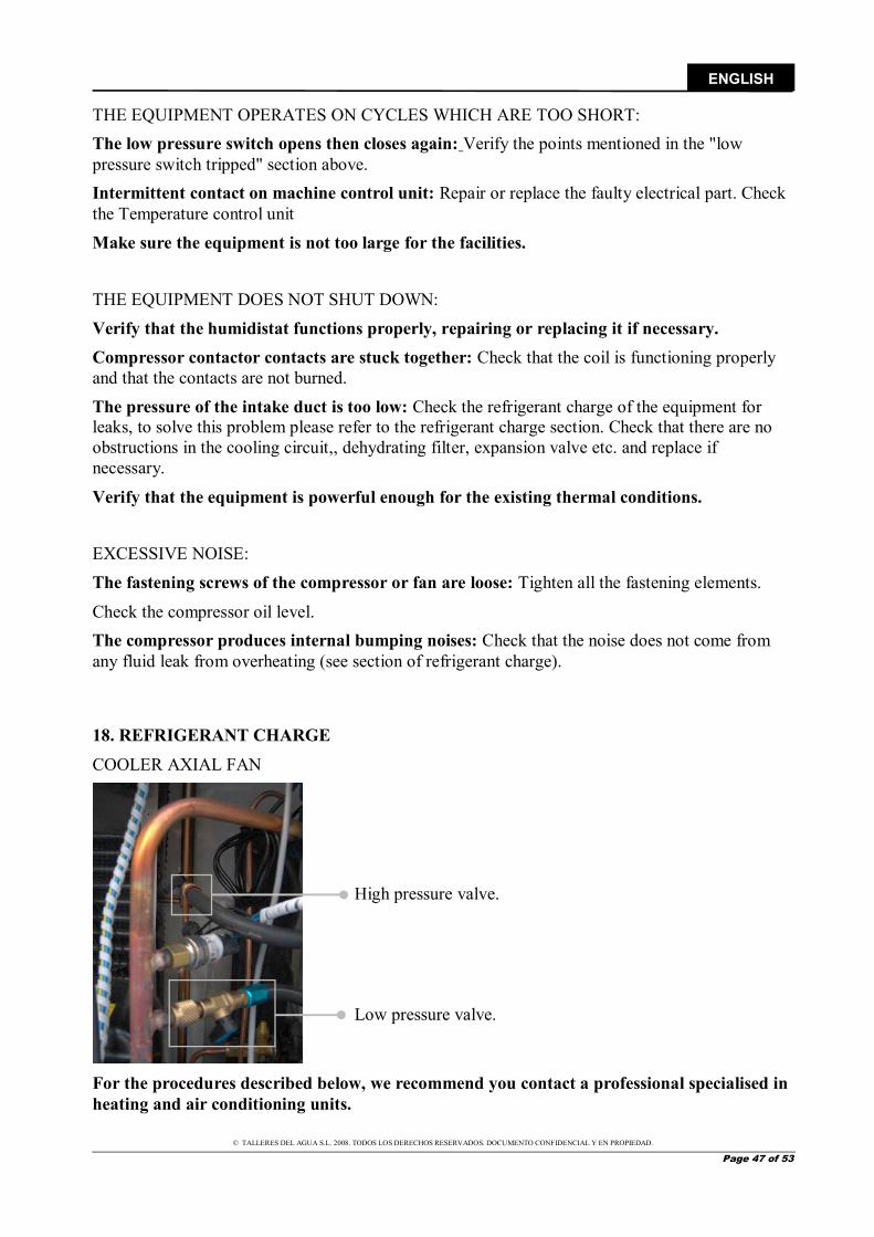
© TALLERES DEL AGUA S.L. 2008. TODOS LOS DERECHOS RESERVADOS. DOCUMENTO CONFIDENCIAL Y EN PROPIEDAD.
Page 47 of 53
ENGLISH
THE EQUIPMENT OPERATES ON CYCLES WHICH ARE TOO SHORT: The low pressure switch opens then closes again: Verify the points mentioned in the "low pressure switch tripped" section above. Intermittent contact on machine control unit: Repair or replace the faulty electrical part. Check the Temperature control unit
Make sure the equipment is not too large for the facilities.
THE EQUIPMENT DOES NOT SHUT DOWN:
Verify that the humidistat functions properly, repairing or replacing it if necessary. Compressor contactor contacts are stuck together: Check that the coil is functioning properly and that the contacts are not burned.
The pressure of the intake duct is too low: Check the refrigerant charge of the equipment for leaks, to solve this problem please refer to the refrigerant charge section. Check that there are no obstructions in the cooling circuit,, dehydrating filter, expansion valve etc. and replace if necessary.
Verify that the equipment is powerful enough for the existing thermal conditions.
EXCESSIVE NOISE:
The fastening screws of the compressor or fan are loose: Tighten all the fastening elements.
Check the compressor oil level. The compressor produces internal bumping noises: Check that the noise does not come from any fluid leak from overheating (see section of refrigerant charge).
18. REFRIGERANT CHARGE COOLER AXIAL FAN
For the procedures described below, we recommend you contact a professional specialised in heating and air conditioning units.
High pressure valve.
Low pressure valve.
© TALLERES DEL AGUA S.L. 2008. TODOS LOS DERECHOS RESERVADOS. DOCUMENTO CONFIDENCIAL Y EN PROPIEDAD.
Page 48 of 53
ENGLISH
DRAINING THE COOLING CIRCUIT:
It is imperative to drain the cooling circuit before charging the refrigerant.
1.- Connect the gauge tubes to the intake pressure lines of the circuit (low pressure) and to the return pressure lines (high pressure). 2.- Connect the main line of the gauge to the vacuum pump. 3.- Open all the valves, including the solenoid and the regulating valves. 4.- Open the valves of the gauge (LO = low pressure valve / HI = high pressure valve). 5.- Activate the vacuum pump and wait until the circuit is completely drained. 6.- Close all valves or stopcocks and disconnect the vacuum pump.
REFRIGERANT CHARGE: The equipment uses R-407-C class refrigerant, which is a blend of 3 different gases with different properties. This is the reason why the gas taken from the refrigerant bottle must be introduced in the low-pressure circuit by means of a charger (expansion system). After having discharged the cooling circuit, and after having installed the charger and connected the flexible tubes of the gauge to the high and low-pressure circuits, we can proceed with the charge:
1.- Connect the main line of the gauge to the R-407 bottle stopcock. 2.- Open the bottle stopcock and purge the section of tubing. 3.- Open the high-pressure valve. 4-. Pressurise the equipment to equal the pressure of the bottle. 5.- Close all gauge valves. 6.- Start the machine. The low-pressure switch may be activated. To continue with the charge, you must disconnect the low-pressure switch in the electrical panel (just while the charging operation is underway). 7.- Open the low-pressure valve until the pressure is above the trip point of the low-pressure switch. 8.- Once in a while, close the LO valve of the gauges in order to confirm the real pressure of intake. 9.- Verify that the outflow pressure is not above the normal range for normal working conditions. 10.- When the correct weight of refrigerant has been charged, close the LO valve. 11.- When the equipment is functioning according to the specified working conditions, close the valve of the charging bottle and disconnect the tubes taking precautions regarding gas purge. 12.- Place the caps on the supply and return lines of the compressor.
DETECTING LEAKS: Leaks may appear due to various reasons. Leakage risk may be greatly reduced if the equipment is correctly installed by qualified personnel and by taking certain precautions in the assembly of the equipment.
Symptoms of a leak Leaks will cause a decrease in the refrigerant charge in the equipment. Low refrigerant charge may be the cause of:
© TALLERES DEL AGUA S.L. 2008. TODOS LOS DERECHOS RESERVADOS. DOCUMENTO CONFIDENCIAL Y EN PROPIEDAD.
Page 49 of 53
ENGLISH
◙ The temperature of the evaporating unit is too low. This may be caused by an obstructed fluid line or the incorrect operation of a capillary. The consequences may be very serious, for example ice may form on evaporating unit, etc.
◙ The compressor is functioning on cycles which are too short. This may also be due to incorrect functioning of control humidistat.
◙ Compressor is overheated: low gas charge makes for insufficient flow of vapours to cool the compressor. This may cause the tripping of the internal thermal indicator of the compressor.
◙ The compressor operates continuously, there is not enough refrigerant to obtain the desired results, and since the specified temperatures are not reached, the equipment does not shut down.
In any case, it is better not to wait until a leak appears, and for this reason, it is recommended to inspect the equipment regularly.
METHODS FOR SEARCHING FOR A GAS LEAK:
There are various tools on the market used in order to detect leaks, although not all of them are sufficiently sensitive to certain types of refrigerants. It is very important to choose an adequate detector for the refrigerant used for this equipment and that the maintenance guidelines to be followed.
You can also use soap bubbles (liquid detergent in a spray bottle) to detect leaks. Other methods such as halogen lighters and additives may also be used to detect leaks.
THE R-407-C GAS: The R-407-C is NOT AN INFLAMMALBE gas; it has no flash point, and so is not subjected to the rules and regulations of the transportation of inflammable gases. The R-407-C does not irritate the skin, eyes or mucous membranes and does not produce any side-effects. It has a very low level of toxicity for one or many repeated exposures; it does not cause cancer or mutations. The R-407-C is susceptible may cause freezing if it comes into contact with the skin, due to its immediate evaporation. As with all hydrocarbons, whether they are halogenated or not, the R-407-C gas may, although it has a very low level of toxicity, cause anaesthetic or pre-anaesthetic conditions if inhaled deeply and within a closed area.
19. WARRANTY AND GENERAL CONDITIONS The manufacturer guarantees the quality of the equipment specified in the LETTER OF WARRANTY which should accompany this technical manual for start-up and other procedures. The manufacturer's warranty does not cover breakage or damage resulting from the following circumstances:
Inadequate use or installation. Failure to follow the cleaning and maintenance instructions. Inappropriate chemical conditions. Operations done by unqualified personnel. Damage caused by inadequate risks. Damage caused by natural disasters.

© TALLERES DEL AGUA S.L. 2008. TODOS LOS DERECHOS RESERVADOS. DOCUMENTO CONFIDENCIAL Y EN PROPIEDAD.
Page 50 of 53
ENGLISH
20. PRODUCT RECYCLING This u it has a ef ige atio gas i li uid state a d ele t i al o po e ts. Whe the heat pu p ea hes the e d of its se vi e life, it should e dis a tled y a autho ised o pa y o ay e t a spo ted to the pla e assig ed y the o espo di g lo al autho ities.
With the ai of edu i g the a ou t of ele t i al a d ele t o i e uip e t esidues a d the da ge of thei o po e ts, to p o ote the e li g of the e uip e t a d the app e iatio of thei esidues, a d to dete i e a suita le a age e t that atte pts to i p o e the effe ti e ess of the e i o e tal p ote tio , a se ies of egulatio s appli a le to the a ufa tu i g of the p odu t a d othe s elated to the o e t e i o e tal a age e t he the e o e esidues ha e ee i ple e ted.
It is also e isaged to i p o e the e i o e tal eha iou of all the age ts i ol ed i the se i e life of the ele t i al a d ele t o i e uip e t, su h as the p odu e s, dist i uto s, use s a d, spe iall , those age ts di e tl i ol ed i the a age e t of the esidues de i ed f o this e uip e t.
As of August , he ou ish to th o a a this u it, ou ha e t o possi le etu s ste s: - if ou a ui e a e o e that is of a e ui ale t t pe o it has the sa e fu tio s as the o e th o a a , ou ould ha d it o e at o ost to the dist i uto . - o ou ould take it to the pla e so sele ted the lo al autho ities. The u its a e la elled ith the s ol of a ossed out heeled u ish o tai e . This s ol de otes the eed fo its sele ti e a d diffe e tiated olle tio f o the est of u a u ish. Possi le effe ts o e the e i o e t o hu a health of the da ge ous ate ials it a o tai . PVC The ost used plastif i g age t i the diffe e t PVC appli atio s is the DEHP di- -eth l he l phthalate . The tests o du ted i diffe e t la o ato ies de o st ate that it does ot p ese t isks fo hu a health i the o e t atio le els so used i fi ished a ti les, a o di g to the i fo atio f o the Ge a BUA Ad iso Bod fo the Rele a t E i o e t of the E isti g Su sta es a d the VGA Ge a Health Autho it a o g othe s. The esults of these tests, togethe ith the data olle ted i
iodeg adatio studies, o fi that the DEHP a ot e o side ed da ge ous fo the e i o e t. All additi es used i the PVC fo ulatio s a d the efo e i the food i dust appli atio s a e pe fe tl egulated at oth Eu opea a d Spa ish le el.
I Eu ope, the EC Di e ti e / /EU, late odified the / /EU. I Spai , e should e tio the Ro al De ees / of Ap il , late o fi ed the / of Ju e .
Mode te h olog applied fo ea s i the PVC p odu tio pla ts allo us to state that the do ot ea a da ge fo the e i o e t. The se i e life a al ses SLA de o st ate that the e i o e tal i pa t of the PVC is e ui ale t o e e o e fa ou a le tha those o espo di g to othe ate ials.
TITANIUM
Health effe ts. Ele e tal tita iu a d tita iu dio ide a e of a lo o de of to i it . Hu a s o e e posed to tita iu dio ide ia i halatio a de elop slight ha ges i lu gs.
Effe ts of o ere posure to tita iu po der. Dust i halatio a ause tight ess a d pai i hest, oughi g, a d diffi ult i eathi g. Co ta t ith ski o e es a ause i itatio . Routes of e t : I halatio , ski o ta t, e e o ta t.
Car i oge i it . The I te atio al Age fo Resea h o Ca e IARC has listed tita iu dio ide ithi G oup The age t is ot lassifia le as to its a i oge i it to hu a s.
E iro e tal effe ts. Lo to i it . No egati e e i o e tal effe ts of tita iu ha e ee epo ted.
WARRANTY CERTIFICATE
. WARRANTY COVERAGE
© TALLERES DEL AGUA S.L. 2008. TODOS LOS DERECHOS RESERVADOS. DOCUMENTO CONFIDENCIAL Y EN PROPIEDAD.
Page 51 of 53
ENGLISH
. I a o da e ith these p o isio s, the sales a gua a tees that the p odu t o espo di g to this a a t the p odu t does ot p ese t a o - o fo a e at the o e t of its deli e . . The a a t pe iod of the p odu t is of t o ea s a d it ill take effe t as of the ti e of deli e to the u e . . If a P odu t o - o fo a e o u s a d the u e otifies it to the sales a du i g the Wa a t Pe iod, the sales a should epai
o epla e the P odu t at his o ost i the app op iate pla e, u less it is i possi le o disp opo tio ate. . Whe the P odu t a ot e epai ed o e epla ed, the u e shall e a le to ask fo a p opo tio al p i e edu tio o , if the o o fo a e is suffi ie tl i po ta t, the dis ha ge of the sales o t a t. . The epla ed o epai ed pa ts i tue of this a a t ill ot e te d the a a t te of the o igi al P odu t, although the ill
ha e its o a a t . . Fo the effe ti e ess of this a a t , the u e ill ha e to edit the a uisitio date a d deli e date of the P odu t. . Whe the deli e of the P odu t to the u e had ee o e tha si o ths efo e a d the u e alleges o - o fo a e ith the
P odu t, the u e ill ha e to p o e the o igi a d e iste e of the alleged fault. . The p ese t Wa a t Ce tifi ate does ot li it o p ejudges the ights the o su e s a e e titled i tue of lo al p e aili g a d
appli a le egulatio s.
. CONDITIONS TO WARRANTY . This a a t o e s the p odu ts efe ed to i this a ual. . This Wa a t Ce tifi ate ill e solel appli a le i the ou t ies of the Eu opea U io . . Fo the effe ti e ess of this a a t , the u e ill ha e to st i tl follo the a ufa tu e i st u tio s i luded i the
do u e tatio e losed ith the P odu t, he e e this a a t is appli a le a o di g to the P odu t a ge a d odel. . Whe a ale da fo the su stitutio , ai te a e o lea i g of e tai pa ts o o po e ts of the P odu t is spe ified, the Wa a t ill o l e alid he the ale da has ee o se ed.
. LIMITACIONES . This a a t ill e solel appli a le to those sales to o su e s, ei g u de stood o su e s as those people ho a ui e the
P odu t ith a pu pose that does ot fall ithi the s ope of thei p ofessio al a ti it .
. No a a t is g a ted efe ed to the ea a d tea aused the use of the P odu t. I elatio to the pa ts, o po e ts a d/o o su a le ate ials su h as atte ies, light ul s et , it ill efe to the p o isio s of the do u e tatio e losed ith the P odu t, he appli a le.
. The a a t does ot o e those ases he e the P odu t: I has ee i o e tl t eated; II has ee epai ed, ai tai ed o a ipulated a o autho ized pe so , o III has ee epai ed o ai tai ed ith o o igi al pie es
Whe the o - o fo a e of the P odu t is a o se ue e of a i o e t i stallatio o sta t-up, this a a t ill o l o e those i stallatio s o sta t-ups i luded i the o t a t of sale of the P odu t a d a ied out the sales a o u de his/he espo si ilit .
PRODUCTS: AIR/WATER COOLER EF
DECLARATION OF CONFORMITY
Machine safety directive 2006/42/EC. Electromagnetic compatibility directive 2004/108/EC and its modifications.
Low-voltage equipment directive 2006/95/EC. Directive 2000/14/CE concerning noise produced by equipment for outdoors use, as amended by Directive 2005/88/EC.
Restrictions in the use of certain risky substances in the electrical and electronic instruments 2002/95/EC (RoHS). Relative to the electrical and electronic waste products 2002/96/EC (RAEE).
Relative to the electrical and electronic instruments and the management of their waste products Spanish R.D. 208/2005. The registration, the evaluation, the authorization and the restriction of the chemical substances EC Nº 1907/2006 (REACH).
Signed the present conformity evidence: Los Corrales de Buelna January 2018
Mr. Jose Manuel Aquilue. Chief Executive Officer of B-39390968


NOS RESERVAMOS EL DERECHO DE CAMBIAR TOTAL O PARCIALMENTE LAS CARACTERÍSTICAS DE NUESTROS ARTÍCULOS O CONTENIDO DE ESTE DOCUMENTO SIN PREVIO AVISO.
WE RESERVE THE RIGHT TO CHANGE ALL OR PART OF THE FEATURES OF THE ARTICLES OR CONTENTS OF THIS DOCUMENT,
WITHOUT PRIOR NOTICE.