Embed Size (px)
Citation preview

EM-1
ENGINE MECHANICAL
B ENGINE
CONTENTS
C
D
E
F
G
H
I
J
K
L
M
SECTION EMA
EM
Revision: 2005 August 2005 350Z
ENGINE MECHANICAL
PRECAUTIONS .......................................................... 4Precautions for Procedures without Cowl Top Cover ..... 4Precautions for Battery Service ................................ 4Precautions for Drain Engine Coolant ...................... 4Precautions for Disconnecting Fuel Piping .............. 4Precautions for Removal and Disassembly ............. 4Precautions for Inspection, Repair and Replace-ment ......................................................................... 4Precautions for Assembly and Installation ............... 4Parts Requiring Angle Tightening ............................. 5Precautions for Liquid Gasket .................................. 5
REMOVAL OF LIQUID GASKET SEALING .......... 5LIQUID GASKET APPLICATION PROCEDURE ..... 5
PREPARATION ........................................................... 7Special Service Tools ............................................... 7Commercial Service Tools ........................................ 9
NOISE, VIBRATION AND HARSHNESS (NVH) TROUBLESHOOTING .............................................. 12
NVH Troubleshooting — Engine Noise .................. 12Use the Chart Below to Help You Find the Cause of the Symptom. ..................................................... 13
DRIVE BELTS ........................................................... 14Checking Drive Belts .............................................. 14Tension Adjustment ................................................ 14
ALTERNATOR AND POWER STEERING OIL PUMP BELT ........................................................ 15A/C COMPRESSOR BELT ................................. 15
Removal and Installation ........................................ 15REMOVAL ........................................................... 15INSTALLATION ................................................... 15
AIR CLEANER AND AIR DUCT ............................... 16Removal and Installation ........................................ 16
REMOVAL ........................................................... 16INSPECTION AFTER REMOVAL ....................... 17INSTALLATION ................................................... 17
Changing Air Cleaner Filter .................................... 17REMOVAL ........................................................... 17INSTALLATION ................................................... 17
INTAKE MANIFOLD COLLECTOR .......................... 18Removal and Installation ........................................ 18
REMOVAL ........................................................... 18INSPECTION AFTER REMOVAL ....................... 20INSTALLATION ................................................... 21
INTAKE MANIFOLD ................................................. 23Removal and Installation ........................................ 23
REMOVAL ........................................................... 23INSPECTION AFTER REMOVAL ....................... 23INSTALLATION ................................................... 24
EXHAUST MANIFOLD AND THREE WAY CATA-LYST .......................................................................... 25
Removal and Installation ........................................ 25REMOVAL ........................................................... 25INSPECTION AFTER REMOVAL ....................... 27INSTALLATION ................................................... 27
OIL PAN AND OIL STRAINER ................................. 29Removal and Installation ........................................ 29
REMOVAL ........................................................... 29INSPECTION AFTER REMOVAL ....................... 31INSTALLATION ................................................... 32INSPECTION AFTER INSTALLATION ................ 34
IGNITION COIL ......................................................... 35Removal and Installation ........................................ 35
REMOVAL ........................................................... 35INSTALLATION ................................................... 35
SPARK PLUG (PLATINUM-TIPPED TYPE) ............. 36Removal and Installation ........................................ 36
REMOVAL ........................................................... 36INSPECTION AFTER REMOVAL ....................... 36INSTALLATION ................................................... 37
FUEL INJECTOR AND FUEL TUBE ........................ 38Removal and Installation ........................................ 38
REMOVAL ........................................................... 38INSTALLATION ................................................... 40INSPECTION AFTER INSTALLATION ................ 43
ROCKER COVER ..................................................... 44Removal and Installation ........................................ 44
REMOVAL ........................................................... 44INSTALLATION ................................................... 45

EM-2Revision: 2005 August 2005 350Z
FRONT TIMING CHAIN CASE ................................. 47Removal and Installation ........................................ 47
REMOVAL ........................................................... 47INSTALLATION .................................................... 51INSPECTION AFTER INSTALLATION ................ 57
TIMING CHAIN .......................................................... 59Removal and Installation (Except for 35th Anniver-sary) ........................................................................ 59
REMOVAL ........................................................... 61INSPECTION AFTER REMOVAL ........................ 68INSTALLATION .................................................... 69INSPECTION AFTER INSTALLATION ................ 80
Removal and Installation (For 35th Anniversary) .... 81REMOVAL ........................................................... 82INSPECTION AFTER REMOVAL ........................ 89INSTALLATION .................................................... 90INSPECTION AFTER INSTALLATION .............. 101
CAMSHAFT ............................................................. 102Removal and Installation ...................................... 102
REMOVAL ......................................................... 103INSPECTION AFTER REMOVAL ...................... 104INSTALLATION .................................................. 107INSPECTION AFTER INSTALLATION .............. 112
Valve Clearance .................................................... 113INSPECTION ..................................................... 113ADJUSTMENT .................................................. 116
OIL SEAL ................................................................ 117Removal and Installation of Valve Oil Seal ........... 117
REMOVAL ......................................................... 117INSTALLATION .................................................. 117
Removal and Installation of Front Oil Seal ........... 118REMOVAL ......................................................... 118INSTALLATION .................................................. 118
Removal and Installation of Rear Oil Seal ............ 118REMOVAL ......................................................... 118INSTALLATION .................................................. 119
CYLINDER HEAD ................................................... 120On-Vehicle Service ............................................... 120
CHECKING COMPRESSION PRESSURE ....... 120Removal and Installation ...................................... 121
REMOVAL ......................................................... 121INSPECTION AFTER REMOVAL ...................... 122INSTALLATION .................................................. 123INSPECTION AFTER INSTALLATION .............. 124
Disassembly and Assembly .................................. 125DISASSEMBLY ................................................. 125ASSEMBLY ....................................................... 126
Inspection After Disassembly ............................... 127VALVE DIMENSIONS ........................................ 127VALVE GUIDE CLEARANCE ............................ 128VALVE GUIDE REPLACEMENT ....................... 128VALVE SEAT CONTACT ................................... 130VALVE SEAT REPLACEMENT ......................... 130VALVE SPRING SQUARENESS ....................... 131VALVE SPRING DIMENSIONS AND VALVE SPRING PRESSURE LOAD ............................. 131
ENGINE ASSEMBLY ...............................................132Removal and Installation .......................................132
REMOVAL ..........................................................133INSTALLATION ..................................................135INSPECTION AFTER INSTALLATION ..............137
CYLINDER BLOCK .................................................138Disassembly and Assembly ..................................138
DISASSEMBLY ..................................................140ASSEMBLY ........................................................145
How to Select Piston and Bearing ........................153DESCRIPTION ..................................................153HOW TO SELECT PISTON ...............................153HOW TO SELECT CONNECTING ROD BEAR-ING .....................................................................154HOW TO SELECT MAIN BEARING ..................155
Inspection After Disassembly ................................158CRANKSHAFT END PLAY ................................158CONNECTING ROD SIDE CLEARANCE .........158PISTON TO PISTON PIN OIL CLEARANCE .....158PISTON RING SIDE CLEARANCE ...................159PISTON RING END GAP ..................................160CONNECTING ROD BEND AND TORSION .....160CONNECTING ROD BIG END DIAMETER ......161CONNECTING ROD BUSHING OIL CLEAR-ANCE .................................................................161CYLINDER BLOCK DISTORTION ....................162MAIN BEARING HOUSING INNER DIAMETER .162PISTON TO CYLINDER BORE CLEARANCE ..163CRANKSHAFT MAIN JOURNAL DIAMETER ...164CRANKSHAFT PIN JOURNAL DIAMETER ......164CRANKSHAFT OUT-OF-ROUND AND TAPER .164CRANKSHAFT RUNOUT ..................................165CONNECTING ROD BEARING OIL CLEAR-ANCE .................................................................165MAIN BEARING OIL CLEARANCE ...................166CRUSH HEIGHT OF MAIN BEARING ..............166CRUSH HEIGHT OF CONNECTING ROD BEARING ...........................................................167MAIN BEARING CAP BOLT OUTER DIAMETER .167CONNECTING ROD BOLT OUTER DIAMETER (EXCEPT FOR 35TH ANNIVERSARY) .............167FLYWHEEL DEFLECTION (M/T MODELS) ......167MOVEMENT AMOUNT OF FLYWHEEL (M/T MODELS) ...........................................................167DRIVE PLATE (A/T MODELS) ...........................168OIL JET ..............................................................168OIL JET RELIEF VALVE ....................................168
SERVICE DATA AND SPECIFICATIONS (SDS) ....169Standard and Limit ................................................169
GENERAL SPECIFICATIONS ...........................169DRIVE BELT ......................................................170INTAKE MANIFOLD COLLECTOR, INTAKE MANIFOLD AND EXHAUST MANIFOLD ..........170SPARK PLUG ....................................................170CAMSHAFT AND CAMSHAFT BEARING .........171CYLINDER HEAD ..............................................173CYLINDER BLOCK ............................................176PISTON, PISTON RING AND PISTON PIN ......177CONNECTING ROD ..........................................178

EM-3
C
D
E
F
G
H
I
J
K
L
M
EM
A
Revision: 2005 August 2005 350Z
CRANKSHAFT .................................................. 179MAIN BEARING ................................................ 180
CONNECTING ROD BEARING ........................ 181Tightening Torque ................................................. 181

EM-4
PRECAUTIONS
Revision: 2005 August 2005 350Z
PRECAUTIONS PFP:00001
Precautions for Procedures without Cowl Top Cover ABS00H53
When performing the procedure after removing cowl top cover, coverthe lower end of windshield with urethane, etc.
Precautions for Battery Service ABS00B4N
Before disconnecting the battery, lower both the driver and passenger windows. This will prevent any interfer-ence between the window edge and the vehicle when the door is opened/closed. During normal operation, thewindow slightly raises and lowers automatically to prevent any window to vehicle interference. The automaticwindow function will not work with the battery disconnected.
Precautions for Drain Engine Coolant ABS009Y1
Drain engine coolant when engine is cooled.
Precautions for Disconnecting Fuel Piping ABS009Y2
● Before starting work, make sure no fire or spark producing items are in the work area. ● Release fuel pressure before disconnecting and disassembly.● After disconnecting pipes, plug openings to stop fuel leakage.
Precautions for Removal and Disassembly ABS009Y3
● When instructed to use special service tools, use specified tools. Always be careful to work safely, avoidforceful or uninstructed operations.
● Exercise maximum care to avoid damage to mating or sliding surfaces.● Cover openings of engine system with tape or equivalent, if necessary, to seal out foreign materials.● Mark and arrange disassembly parts in an organized way for easy troubleshooting and re-assembly.● When loosening bolts and nuts, as a basic rule, start with the one furthest outside, then the one diagonally
opposite, and so on. If the order of loosening is specified, do exactly as specified. Power tools may beused in the step.
Precautions for Inspection, Repair and Replacement ABS009Y4
Before repairing or replacing, thoroughly inspect parts. Inspect new replacement parts in the same way, andreplace if necessary.
Precautions for Assembly and Installation ABS009Y5
● Use torque wrench to tighten bolts or nuts to specification.● When tightening bolts and nuts, as a basic rule, equally tighten in several different steps starting with the
ones in center, then ones on inside and outside diagonally in this order. If the order of tightening is speci-fied, do exactly as specified.
● Replace with new gasket, packing, oil seal or O-ring.● Dowel pins are used for several parts alignment. When replacing and reassembling with dowel pins, make
sure that dowel pins are installed in the original portion.● Thoroughly wash, clean, and air-blow each part. Carefully check engine oil or engine coolant passages for
any restriction and blockage. ● Avoid damaging sliding or mating surfaces. Completely remove foreign materials such as cloth lint or dust.
Before assembly, oil sliding surfaces well. ● Release air within route when refilling after draining engine coolant.
PIIB3706J

PRECAUTIONS
EM-5
C
D
E
F
G
H
I
J
K
L
M
A
EM
Revision: 2005 August 2005 350Z
● After repairing, start engine and increase engine speed to check engine coolant, fuel, engine oil, andexhaust gases for leakage.
Parts Requiring Angle Tightening ABS009Y6
● Use angle wrench [SST: KV10112100 (BT8653-A)] for the final tightening of the following engine parts: – Cylinder head bolts– Main bearing cap bolts– Connecting rod cap bolts– Crankshaft pulley bolt● Do not use a torque value for final tightening. ● The torque value for these parts are for a preliminary step.● Ensure thread and seat surfaces are clean and coated with engine oil.
Precautions for Liquid Gasket ABS009Y7
REMOVAL OF LIQUID GASKET SEALING● After removing mounting bolts and nuts, separate the mating
surface using seal cutter [SST] and remove old liquid gasketsealing.CAUTION:Be careful not to damage the mating surfaces.
● Tap seal cutter to insert it, and then slide it by tapping on theside as shown in the figure.
● In areas where seal cutter [SST] is difficult to use, use plastichammer to lightly tap the parts, to remove it.CAUTION:If for some unavoidable reason tool such as screwdriver isused, be careful not to damage the mating surfaces.
LIQUID GASKET APPLICATION PROCEDURE1. Using scraper, remove old liquid gasket adhering to the gasket
application surface and the mating surface.● Remove liquid gasket completely from the groove of the gas-
ket application surface, mounting bolts, and bolt holes.2. Wipe the liquid gasket application surface and the mating sur-
face with white gasoline (lighting and heating use) to removeadhering moisture, grease and foreign materials.
3. Attach liquid gasket tube to tube presser [SST: WS39930000( — )].Use Genuine RTV Silicone Sealant or equivalent. Refer toGI-47, "RECOMMENDED CHEMICAL PRODUCTS ANDSEALANTS" .
4. Apply liquid gasket without breaks to the specified location withthe specified dimensions.● If there is a groove for liquid gasket application, apply liquid
gasket to the groove.
PBIC0002E
PBIC0003E
EMA0622D

EM-6
PRECAUTIONS
Revision: 2005 August 2005 350Z
● As for bolt holes, normally apply liquid gasket inside theholes. Occasionally, it should be applied outside the holes.Make sure to read the text of this manual.
● Within five minutes of liquid gasket application, install the mat-ing component.
● If liquid gasket protrudes, wipe it off immediately.● Do not retighten mounting bolts or nuts after the installation.● After 30 minutes or more have passed from the installation, fill
engine oil and engine coolant.CAUTION:If there are specific instructions in this manual, observethem.
SEM159F

PREPARATION
EM-7
C
D
E
F
G
H
I
J
K
L
M
A
EM
Revision: 2005 August 2005 350Z
PREPARATION PFP:00002
Special Service Tools ABS009Y8
The actual shapes of Kent-Moore tools may differ from those of special service tools illustrated here.
Tool number(Kent-Moore No.)Tool name
Description
ST0501S000( — )Engine stand assembly1. ST05011000( — )Engine stand2. ST05012000( — )Base
Disassembling and assembling engine
KV10106500( — )Engine stand shaft
KV10117000(J41262)Engine sub-attachment
KV10117000 has been replaced with KV10117001 (KV10117000 is no longer in production, but it is usable).
KV10117001( — )Engine sub-attachment
Installing on cylinder block
KV10116200(J26336-A)Valve spring compressor1. KV10115900(J26336-20)Attachment2.KV10109220( — )Adapter
Disassembling valve mechanismPart (1) is a component of KV10116200 (J26336-A), but Part (2) is not so.
KV10107902(J38959)Valve oil seal puller
Replacing valve oil seal
NT042
NT028
NT373
NT372
PBIC1650E
NT011

EM-8
PREPARATION
Revision: 2005 August 2005 350Z
—(J39386)Valve oil seal drift
Installing valve oil seal
EM03470000(J8037)Piston ring compressor
Installing piston assembly into cylinder bore
ST16610001(J23907)Pilot bushing puller
Removing pilot bushing (M/T models) or pilot converter (A/T models)
KV10111100(J37228)Seal cutter
Removing oil pan (lower and upper), front and rear timing chain case, etc.
WS39930000( — )Tube presser
Pressing the tube of liquid gasket
KV10112100(BT8653-A)Angle wrench
Tightening bolts for bearing cap, cylinder head, etc. in angle
KV10117100(J3647-A)Heated oxygen sensor wrench
Loosening or tightening heated oxygen sensor 2For 22 mm (0.87 in) width hexagon nut
Tool number(Kent-Moore No.)Tool name
Description
NT024
NT044
NT045
NT046
NT052
NT014
NT379

PREPARATION
EM-9
C
D
E
F
G
H
I
J
K
L
M
A
EM
Revision: 2005 August 2005 350Z
Commercial Service Tools ABS009Y9
KV10114400(J38365)Heated oxygen sensor wrench
Loosening or tightening air fuel ratio sensor 1a: 22 mm (0.87 in)
KV10117700(J44716)Ring gear stopper
Removing and installing crankshaft pulley
—(J-45488)Quick connector release
Removing fuel tube quick connectors in engine room
Tool number(Kent-Moore No.)Tool name
Description
NT636
NT822
PBIC0198E
(Kent-Moore No.)Tool name
Description
Power tool Loosening bolts and nuts
(BT3373-F)Belt tension gauge
Checking drive belt tension
TORX socket Removing and installing flywheelSize: T55
PBIC0190E
AMA126
PBIC1113E

EM-10
PREPARATION
Revision: 2005 August 2005 350Z
( — )Manual lift table caddy
Removing and installing engine
(J24239-01)Cylinder head bolt wrench
Loosening and tightening cylinder head bolt, and used with angle wrench [SST: KV10112100 (BT8653-A)]a: 13 (0.51) dia.b: 12 (0.47)c: 10 (0.39)Unit: mm (in)
( — )Spark plug wrench
Removing and installing spark plug
( — )Valve seat cutter set
Finishing valve seat dimensions
( — )Piston ring expander
Removing and installing piston ring
( — )Valve guide drift
Removing and installing valve guideIntake and Exhaust:a: 9.5 mm (0.374 in) dia.b: 5.5 mm (0.217 in) dia.
( — )Valve guide reamer
(1): Reaming valve guide inner hole(2): Reaming hole for oversize valve guideIntake and Exhaust:d1 : 6.0 mm (0.236 in) dia.d2 : 10.2 mm (0.402 in) dia.
(Kent-Moore No.)Tool name
Description
ZZA1210D
NT583
NT047
NT048
NT030
NT015
NT016

PREPARATION
EM-11
C
D
E
F
G
H
I
J
K
L
M
A
EM
Revision: 2005 August 2005 350Z
(J-43897-18)(J-43897-12)Oxygen sensor thread cleaner
Reconditioning the exhaust system threads before installing a new air fuel ratio sensor and heated oxygen sensor (Use with anti-seize lubricant shown below.)a: J-43897-18 [18 mm (0.71 in) dia.] for zirconia heated oxygen sensor and air fuel ratio sensorb: J-43897-12 [12 mm (0.47 in) dia.] for titania heated oxygen sensor
( — )Anti-seize lubricant (Permatex 133AR or equivalent meeting MIL specification MIL-A-907)
Lubricating oxygen sensor thread cleaning tool when reconditioning exhaust system threads
(Kent-Moore No.)Tool name
Description
AEM488
AEM489

EM-12
NOISE, VIBRATION AND HARSHNESS (NVH) TROUBLESHOOTING
Revision: 2005 August 2005 350Z
NOISE, VIBRATION AND HARSHNESS (NVH) TROUBLESHOOTING PFP:00003
NVH Troubleshooting — Engine Noise ABS009YA
PBIC3605E

NOISE, VIBRATION AND HARSHNESS (NVH) TROUBLESHOOTING
EM-13
C
D
E
F
G
H
I
J
K
L
M
A
EM
Revision: 2005 August 2005 350Z
Use the Chart Below to Help You Find the Cause of the Symptom. ABS009YB
1. Locate the area where noise occurs.2. Confirm the type of noise.3. Specify the operating condition of engine.4. Check specified noise source.If necessary, repair or replace these parts.
A: Closely related B: Related C: Sometimes related —: Not related
Location of noise
Type of noise
Operating condition of engine
Source of noise
Check itemRefer-
ence pageBefore warm-
up
After warm-
up
When start-ing
When idling
When racing
While driving
Top of engineRocker coverCylinder head
Ticking or clicking
C A — A B —Tappet noise
Valve clearance EM-113
Rattle C A — A B CCamshaft bearing noise
Camshaft runoutCamshaft journal oil clearance
EM-104EM-105
Crank-shaft pul-leyCylinder block (Side of engine)Oil pan
Slap or knock
— A — B B —Piston pin noise
Piston to piston pin oil clearanceConnecting rod bush-ing oil clearance
EM-158EM-161
Slap or rap
A — — B B APiston slap noise
Piston to cylinder bore clearancePiston ring side clear-ancePiston ring end gapConnecting rod bend and torsion
EM-163EM-159EM-160EM-160
Knock A B C B B B
Connect-ing rod bearing noise
Connecting rod bush-ing oil clearanceConnecting rod bear-ing oil clearance
EM-161EM-165
Knock A B — A B CMain bearing noise
Main bearing oil clear-anceCrankshaft runout
EM-166EM-165
Front of engineTiming chain case
Tapping or ticking
A A — B B B
Timing chain and chain ten-sioner noise
Timing chain cracks and wearTiming chain tensioner operation
EM-68EM-59
Front of engine
Squeak-ing or fizz-ing
A B — B — C
Drive belts (Sticking or slip-ping)
Drive belts deflection
EM-14
Creaking A B A B A BDrive belts (Slipping)
Idler pulley bearing operation
SquallCreak
A B — B A BWater pump noise
Water pump operationCO-23, "WATER PUMP"
EM-14
DRIVE BELTS
Revision: 2005 August 2005 350Z
DRIVE BELTS PFP:02117
Checking Drive Belts ABS009YC
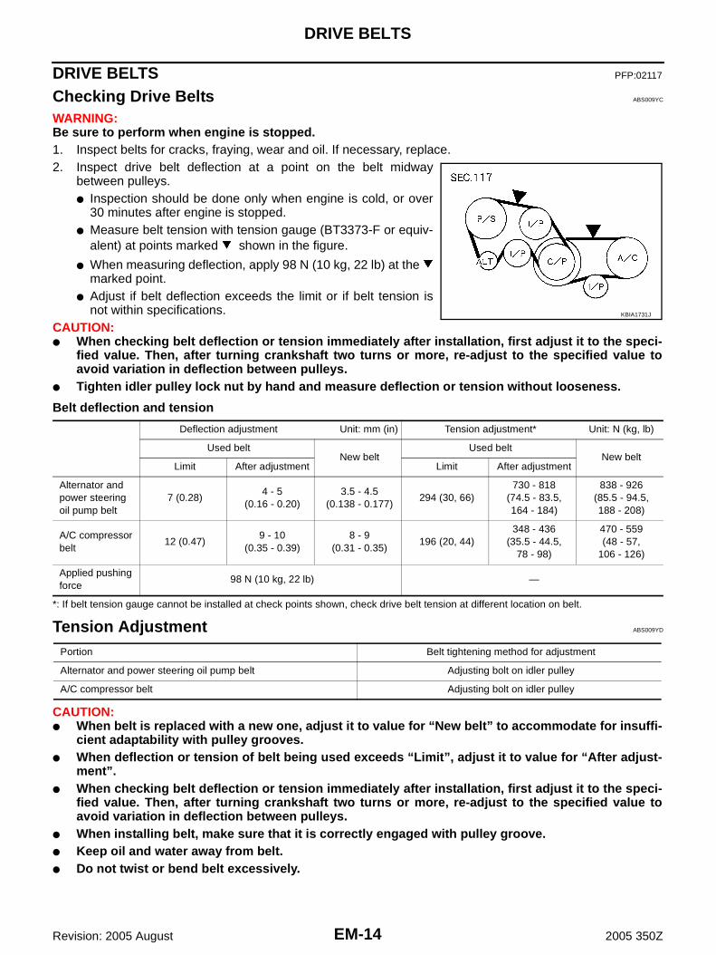
WARNING:Be sure to perform when engine is stopped.1. Inspect belts for cracks, fraying, wear and oil. If necessary, replace.2. Inspect drive belt deflection at a point on the belt midway
between pulleys.● Inspection should be done only when engine is cold, or over
30 minutes after engine is stopped.● Measure belt tension with tension gauge (BT3373-F or equiv-
alent) at points marked shown in the figure.
● When measuring deflection, apply 98 N (10 kg, 22 lb) at the marked point.
● Adjust if belt deflection exceeds the limit or if belt tension isnot within specifications.
CAUTION:● When checking belt deflection or tension immediately after installation, first adjust it to the speci-
fied value. Then, after turning crankshaft two turns or more, re-adjust to the specified value toavoid variation in deflection between pulleys.
● Tighten idler pulley lock nut by hand and measure deflection or tension without looseness.
Belt deflection and tension
*: If belt tension gauge cannot be installed at check points shown, check drive belt tension at different location on belt.
Tension Adjustment ABS009YD
CAUTION:● When belt is replaced with a new one, adjust it to value for “New belt” to accommodate for insuffi-
cient adaptability with pulley grooves.● When deflection or tension of belt being used exceeds “Limit”, adjust it to value for “After adjust-
ment”.● When checking belt deflection or tension immediately after installation, first adjust it to the speci-
fied value. Then, after turning crankshaft two turns or more, re-adjust to the specified value toavoid variation in deflection between pulleys.
● When installing belt, make sure that it is correctly engaged with pulley groove.● Keep oil and water away from belt.● Do not twist or bend belt excessively.
KBIA1731J
Deflection adjustment Unit: mm (in) Tension adjustment* Unit: N (kg, lb)
Used beltNew belt
Used beltNew belt
Limit After adjustment Limit After adjustment
Alternator and power steering oil pump belt
7 (0.28)4 - 5
(0.16 - 0.20)3.5 - 4.5
(0.138 - 0.177)294 (30, 66)
730 - 818(74.5 - 83.5,164 - 184)
838 - 926(85.5 - 94.5,188 - 208)
A/C compressor belt
12 (0.47)9 - 10
(0.35 - 0.39)8 - 9
(0.31 - 0.35)196 (20, 44)
348 - 436(35.5 - 44.5,
78 - 98)
470 - 559(48 - 57,
106 - 126)
Applied pushing force
98 N (10 kg, 22 lb) —
Portion Belt tightening method for adjustment
Alternator and power steering oil pump belt Adjusting bolt on idler pulley
A/C compressor belt Adjusting bolt on idler pulley

DRIVE BELTS
EM-15
C
D
E
F
G
H
I
J
K
L
M
A
EM
Revision: 2005 August 2005 350Z
ALTERNATOR AND POWER STEERING OIL PUMP BELT1. Remove undercover with power tool.2. Loosen idler pulley lock nut (A) and adjust tension by turning
adjusting bolt (B).● For specified belt tension, refer to EM-14, "Checking Drive
Belts" .3. Tighten nut (A).
A/C COMPRESSOR BELT1. Remove undercover with power tool.2. Loosen idler pulley lock nut (C) and adjust tension by turning adjusting bolt (D).
● For specified belt tension, refer to EM-14, "Checking Drive Belts" .3. Tighten nut (C).
Removal and Installation ABS009YE
REMOVAL1. Remove undercover with power tool.2. Remove alternator and power steering oil pump belt. Refer to EM-15, "ALTERNATOR AND POWER
STEERING OIL PUMP BELT" .3. Remove A/C compressor belt. Refer to EM-15, "A/C COMPRESSOR BELT" .
CAUTION:Grease is applied to idler pulley adjusting bolt. Be careful to keep grease away from belt.
INSTALLATION1. Install belts to pulley in the reverse order of removal.
CAUTION:● Make sure belt is correctly engaged with the pulley groove.● Check for engine oil and engine coolant are not adhered belt and each pulley groove.
2. Adjust belt tension. Refer to EM-14, "Tension Adjustment" .3. Tighten each nuts and bolts and nut to the specified torque.4. Make sure that tension of each belt is within the standard.
: 31.4 - 38.2 N·m (3.2 - 3.9 kg-m, 24 - 28 ft-lb)
SBIA0532E
: 30.4 - 39.2 N·m (3.1 - 4.0 kg-m, 23 - 28 ft-lb)

EM-16
AIR CLEANER AND AIR DUCT
Revision: 2005 August 2005 350Z
AIR CLEANER AND AIR DUCT PFP:16500
Removal and Installation ABS009YF
REMOVAL1. Remove clips, and slide air duct (inlet) frontward, disengage
clips and air cleaner case.NOTE:When removing air duct (inlet), remove front bumper andbumper fascia stay radiator core support center. Refer to EI-14,"FRONT BUMPER" and BL-19, "RADIATOR CORE SUPPORT".
2. Disconnect harness connector from mass air flow sensor.3. Disconnect PCV hose.4. Remove air cleaner case/mass air flow sensor assembly and air duct assembly disconnecting their joints.
● Add marks as necessary for easier installation.5. Remove mass air flow sensor from air cleaner case.
CAUTION:Handle mass air flow sensor with care.● Do not shock it.
1. Air cleaner filter 2. Holder 3. Air cleaner case
4. Clip 5. Air duct (inlet) 6. Grommet
7. Collar 8. Grommet 9. O-ring
10. Mass air flow sensor 11. Clamp 12. Air duct
13. PCV hose 14. Clamp
PBIC2301E
KBIA1734E

AIR CLEANER AND AIR DUCT
EM-17
C
D
E
F
G
H
I
J
K
L
M
A
EM
Revision: 2005 August 2005 350Z
● Do not disassemble it.● Do not touch its sensor.
INSPECTION AFTER REMOVALInspect air duct for crack or tear.● If anything found, replace air duct.
INSTALLATIONNote the following, and install in the reverse order of removal.● Align marks. Attach each joint. Screw clamps firmly.
Changing Air Cleaner Filter ABS009YG
REMOVAL1. Unhook clips, and lift holder.2. Remove air cleaner filter.
INSTALLATIONInstallation is the reverse order of removal.
PBIC1118E

EM-18
INTAKE MANIFOLD COLLECTOR
Revision: 2005 August 2005 350Z
INTAKE MANIFOLD COLLECTOR PFP:14003
Removal and Installation ABS009YH
REMOVALWARNING:● To avoid the danger of being scalded, do not drain the engine coolant when the engine is hot.● Gasket for intake manifold collector (upper) is secured together with mounting bolt for intake man-
ifold collector (lower). Thus, even when only gasket for upper side is replaced, gasket for lowerside must be also replaced.
1. Remove tower bar. Refer to FSU-20, "TOWER BAR" .
1. Electric throttle control actuator 2. Gasket 3. Vacuum hose
4.EVAP canister purge volume control solenoid valve
5. Bracket 6. Intake manifold collector (upper)
7. Intake manifold collector cover 8. Gasket 9. Water hose
10. Bracket 11. Water hose 12. PCV hose
13. Intake manifold collector (lower)
PBIC3490E
INTAKE MANIFOLD COLLECTOR
EM-19
C
D
E
F
G
H
I
J
K
L
M
A
EM
Revision: 2005 August 2005 350Z
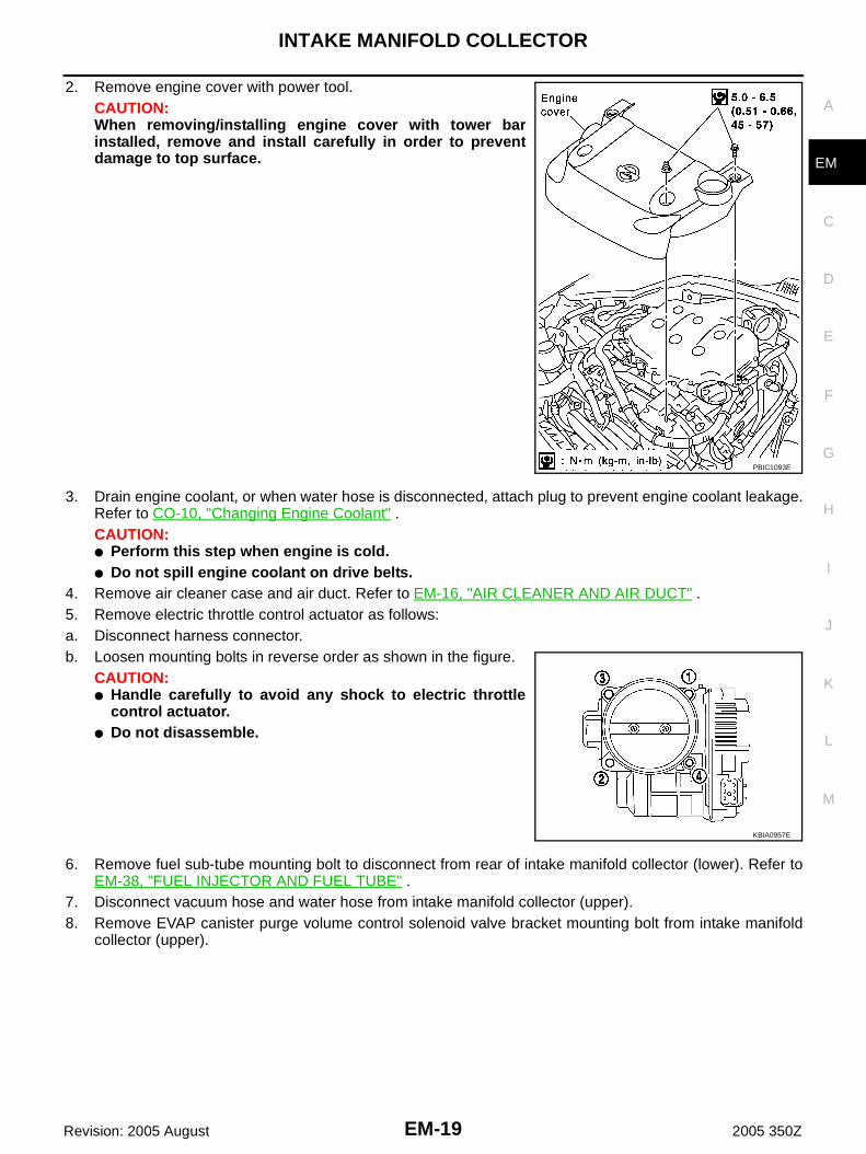
2. Remove engine cover with power tool.CAUTION:When removing/installing engine cover with tower barinstalled, remove and install carefully in order to preventdamage to top surface.
3. Drain engine coolant, or when water hose is disconnected, attach plug to prevent engine coolant leakage.Refer to CO-10, "Changing Engine Coolant" .CAUTION:● Perform this step when engine is cold.● Do not spill engine coolant on drive belts.
4. Remove air cleaner case and air duct. Refer to EM-16, "AIR CLEANER AND AIR DUCT" .5. Remove electric throttle control actuator as follows:a. Disconnect harness connector.b. Loosen mounting bolts in reverse order as shown in the figure.
CAUTION:● Handle carefully to avoid any shock to electric throttle
control actuator.● Do not disassemble.
6. Remove fuel sub-tube mounting bolt to disconnect from rear of intake manifold collector (lower). Refer toEM-38, "FUEL INJECTOR AND FUEL TUBE" .
7. Disconnect vacuum hose and water hose from intake manifold collector (upper).8. Remove EVAP canister purge volume control solenoid valve bracket mounting bolt from intake manifold
collector (upper).
PBIC1093E
KBIA0957E

EM-20
INTAKE MANIFOLD COLLECTOR
Revision: 2005 August 2005 350Z
9. Loosen mounting bolts with power tool in reverse order asshown in the figure to remove intake manifold collector (upper).
10. Remove PCV hose [between intake manifold collector (lower) and rocker cover (right bank)].11. Loosen mounting bolts with power tool in reverse order as
shown in the figure, and remove the intake manifold collectorcover, gasket, intake manifold collector (lower) and gasket.CAUTION:Cover engine openings to avoid entry of foreign materials.
INSPECTION AFTER REMOVALSurface Distortion● Check the surface distortion of both the intake manifold collector
(upper and lower) mating surfaces with straightedge and feelergauge.
● If it exceeds the limit, replace intake manifold collector (upperand/or lower).
PBIC1094E
PBIC0774E
Limit : 0.1 mm (0.004 in)
PBIC0775E

INTAKE MANIFOLD COLLECTOR
EM-21
C
D
E
F
G
H
I
J
K
L
M
A
EM
Revision: 2005 August 2005 350Z
INSTALLATIONNote the following, and install in the reverse order of removal.
Part Installation DirectionReferring to front marks, install parts shown in the figure.
Intake Manifold Collector (Lower)Tighten mounting bolts in numerical order as shown in the figure.NOTE:Tighten mounting bolts to secure gasket (lower), intake manifold col-lector (lower), gasket (upper), and intake manifold collector cover.
Intake Manifold Collector (Upper)● If stud bolts were removed, install them and tighten to the specified torque below.
● Shank length under bolt head varies with bolt location. Installmounting bolts while referring to numbers shown below and inthe figure. (Bolt length does not include pilot portion.)
● Tighten mounting bolts in numerical order as shown in the fig-ure.
Water Hose● Insert hose by 27 to 32 mm (1.06 to 1.26 in) from connector end.
PBIC0776E
PBIC0774E
: 4.9 - 6.9 N·m (0.5 - 0.7 kg-m, 44 - 61 in-lb)
BoltM6 × 25 mm (0.98 in) : 7, 8, 10, 11, 13, 14, 15, 16, 18M6 × 45 mm (1.77 in) : 2, 4, 5M6 × 60 mm (2.36 in) : 1, 3, 6, 9
M6 Nut : 12, 17
PBIC1094E

EM-22
INTAKE MANIFOLD COLLECTOR
Revision: 2005 August 2005 350Z
● Clamp hose at location of 3 to 7 mm (0.12 to 0.28 in) from hose end.
Electric Throttle Control Actuator ● Install gasket with positioning no-protrusion surface upward or downward.● Tighten mounting bolts in numerical order as shown in the fig-
ure.● Perform the “Throttle Valve Closed Position Learning” when har-
ness connector of electric throttle control actuator is discon-nected. Refer to EC-91, "Throttle Valve Closed PositionLearning" .
● Perform the “Idle Air Volume Learning” and “Throttle ValveClosed Position Learning” when electric throttle control actuatoris replaced. Refer to EC-92, "Idle Air Volume Learning" .
KBIA0957E

INTAKE MANIFOLD
EM-23
C
D
E
F
G
H
I
J
K
L
M
A
EM
Revision: 2005 August 2005 350Z
INTAKE MANIFOLD PFP:14003
Removal and Installation ABS009YI
REMOVAL1. Release fuel pressure. Refer to EC-94, "FUEL PRESSURE RELEASE" .2. Remove intake manifold collectors (upper and lower). Refer to EM-18, "INTAKE MANIFOLD COLLEC-
TOR" .3. Remove fuel tube and fuel injector assembly. Refer to EM-38, "FUEL INJECTOR AND FUEL TUBE" .4. Loosen mounting nuts and bolts with power tool in reverse order
as shown in the figure to remove intake manifold.
5. Remove gaskets.CAUTION:Cover engine openings to avoid entry of foreign materials.
INSPECTION AFTER REMOVALSurface Distortion● Check the surface distortion of the intake manifold mating sur-
face with straightedge and feeler gauge.
● If it exceeds the limit, replace intake manifold.
1. Harness bracket 2. Intake manifold 3. Gasket
PBIC2282E
PBIC0778E
Limit : 0.1 mm (0.004 in)
PBIC0870E

EM-24
INTAKE MANIFOLD
Revision: 2005 August 2005 350Z
INSTALLATIONNote the following, and install in the reverse order of removal.
Intake Manifold● If stud bolts were removed, install them and tighten to the specified torque below.
● Tighten all mounting nuts and bolts to the specified torque in twoor more steps in numerical order shown in the figure.
: 9.8 - 11.8 N·m (1.0 - 1.2 kg-m, 87 - 104 in-lb)
1st step: 4.9 - 9.8 N·m (0.5 - 1.0 kg-m, 4 - 7 ft-lb)
2nd step and after: 26.5 - 31.4 N·m (2.7 - 3.2 kg-m, 20 - 23 ft-lb)
PBIC0778E

EXHAUST MANIFOLD AND THREE WAY CATALYST
EM-25
C
D
E
F
G
H
I
J
K
L
M
A
EM
Revision: 2005 August 2005 350Z
EXHAUST MANIFOLD AND THREE WAY CATALYST PFP:14004
Removal and Installation ABS009YJ
REMOVALWARNING:Perform the work when the exhaust and cooling system have completely cooled down.1. Remove tower bar. Refer to FSU-20, "TOWER BAR" .2. Remove engine cover with power tool. Refer to EM-18, "INTAKE MANIFOLD COLLECTOR" .3. Drain engine coolant. Refer to CO-10, "Changing Engine Coolant" .
CAUTION:● Perform this step when engine is cold.● Do not spill engine coolant on drive belts.
4. Remove air cleaner case and air duct. Refer to EM-16, "AIR CLEANER AND AIR DUCT" .5. Remove undercover with power tool.
1. Heated oxygen sensor 2 (bank 1) 2. Three way catalyst (right bank) 3. Gasket
4. Air fuel ratio sensor 1 (bank 1) 5. Exhaust manifold cover (right bank) 6. Exhaust manifold (right bank)
7. Exhaust manifold (left bank) 8. Exhaust manifold cover (left bank) 9. Three way catalyst (left bank)
10. Air fuel ratio sensor 1 (bank 2) 11. Heated oxygen sensor 2 (bank 2)
SBIA0586E

EM-26
EXHAUST MANIFOLD AND THREE WAY CATALYST
Revision: 2005 August 2005 350Z
6. Disconnect harness connector and remove heated oxygen sen-sor 2 on both banks using heated oxygen sensor wrench [SST].● Put marks to identify installation positions of each heated oxy-
gen sensor 2.CAUTION:● Be careful not to damage heated oxygen sensor 2.● Discard any heated oxygen sensor 2 which has been
dropped from a height of more than 0.5 m (19.7 in) onto ahard surface such as a concrete floor; replace with a newsensor.
7. Remove exhaust mounting bracket between three way catalysts (right and left bank) and transmission.Refer to EX-3, "EXHAUST SYSTEM" .
8. Remove three way catalyst.9. Disconnect harness connector and remove air fuel ratio sensor
1 on both banks using heated oxygen sensor wrench [SST].● Put marks to identify installation positions of each air fuel ratio
sensor 1.CAUTION:● Be careful not to damage air fuel ratio sensor 1.● Discard any air fuel ratio sensor 1 which has been
dropped from a height of more than 0.5 m (19.7 in) onto ahard surface such as a concrete floor; replace with a newsensor.
10. Remove water pipe and heater pipe on both right and left side. Refer to CO-30, "WATER OUTLET ANDWATER PIPING" .
11. Remove exhaust manifold cover.12. Loosen mounting nuts with power tool in reverse order as shown
in the figure to remove exhaust manifold.NOTE:Disregard the numerical order No. 7 and 8 in removal.
13. Remove gaskets.CAUTION:Cover engine openings to avoid entry of foreign materials.
PBIC2298E
PBIC2299E
PBIC2042E

EXHAUST MANIFOLD AND THREE WAY CATALYST
EM-27
C
D
E
F
G
H
I
J
K
L
M
A
EM
Revision: 2005 August 2005 350Z
INSPECTION AFTER REMOVALSurface Distortion● Check the surface distortion of the exhaust manifold mating sur-
face with straightedge and feeler gauge.
● If it exceeds the limit, replace exhaust manifold.
INSTALLATIONNote the following, and install in the reverse order of removal.
Exhaust Manifold Gasket● Install in direction shown below. (Follow same procedure for
both banks.)● Locate thick side of port connecting part on right side from tech-
nician’s view.● Locate round press in thick side of port connecting part above
center level line of port.
Exhaust Manifold● If stud bolts were removed, install them and tighten to the specified torque below.
● Install mounting exhaust manifold in numerical order as shownin the figure.NOTE:Tighten nuts No. 1 and 2 in two steps. The numerical order No. 7and 8 shown second step.
Limit : 0.3 mm (0.012 in)
PBIC1096E
KBIA1051E
: 12.7 - 16.7 N·m (1.3 - 1.7 kg-m, 10 - 12 ft-lb)
PBIC2042E

EM-28
EXHAUST MANIFOLD AND THREE WAY CATALYST
Revision: 2005 August 2005 350Z
Air Fuel Ratio Sensor 1 and Heated Oxygen Sensor 2● Install air fuel ratio sensor 1 and heated oxygen sensor 2 in the original position.● Install referring to the following if the installation positions cannot
be identified.
*: Air fuel ratio sensor 1 is the same for both bank 1 andbank 2.
CAUTION:● Before installing a new air fuel ratio sensor 1 and heated
oxygen sensor 2, clean exhaust system threads using oxygen sensor thread cleaner (commercialservice tool: J-43897-18 or J43897-12) and apply anti-seize lubricant (commercial service tool).
● Do not over torque air fuel ratio sensor 1 and heated oxygen sensor 2. Doing so may cause dam-age to air fuel ratio sensor 1 and heated oxygen sensor 2, resulting in the “MIL” coming on.
Glass tube colorAir fuel ratio sensor 1* : BlackHeated oxygen sensor 2 (bank 1) : WhiteHeated oxygen sensor 2 (bank 2) : White
PBIC2652E

OIL PAN AND OIL STRAINER
EM-29
C
D
E
F
G
H
I
J
K
L
M
A
EM
Revision: 2005 August 2005 350Z
OIL PAN AND OIL STRAINER PFP:11110
Removal and Installation ABS009YK
NOTE:To identify 35th Anniversary, refer to GI-52, "Application Item" .
REMOVALWARNING:To avoid the danger of being scalded, do not drain engine oil when engine is hot.
1. Oil pan gasket 2. Oil pan (upper) 3. O-ring
4. Oil pan gasket 5. O-ring 6. Connector bolt
7. Oil filter 8. Oil cooler 9. Relief valve
10. Oil pressure sensor 11. Bracket (A/T models) 12. Washer
(Only for 35th Anniversary)
13. Oil temperature sensor
(Only for 35th Anniversary)
14. Oil strainer 15. Drain plug
16. Drain plug washer 17. Oil pan (lower) 18. Baffle plate
19. Rear plate cover 20. Crankshaft position sensor (POS) 21. Rear cover plate
PBIC3491E

EM-30
OIL PAN AND OIL STRAINER
Revision: 2005 August 2005 350Z
NOTE:To remove oil pan (lower) only, take step 5 and step 7, then step 20. Step 1 to 4, step 6 and step 8 to 19 areunnecessary.1. Remove hood assembly. Refer to BL-13, "HOOD" .2. Remove tower bar. Refer to FSU-20, "TOWER BAR" .3. Remove engine cover with power tool. Refer to EM-18, "INTAKE MANIFOLD COLLECTOR" .4. Remove air duct. Refer to EM-16, "AIR CLEANER AND AIR DUCT" .5. Drain engine oil. Refer to LU-10, "Changing Engine Oil" .
CAUTION:● Perform this step when engine is cold.● Do not spill engine oil on drive belts.
6. Drain engine coolant. Refer to CO-10, "Changing Engine Coolant" .CAUTION:● Perform this step when engine is cold.● Do not spill engine coolant on drive belts.
7. Remove undercover with power tool.8. Install engine slinger to sling engine assembly for positioning. Refer to EM-132, "ENGINE ASSEMBLY" .9. Remove front suspension member. Refer to FSU-19, "FRONT SUSPENSION MEMBER" .10. Remove drive belts. Refer to EM-14, "DRIVE BELTS" .11. Remove alternator. Refer to SC-21, "CHARGING SYSTEM" .12. Remove starter motor. Refer to SC-10, "STARTING SYSTEM" .13. Remove idler pulley and bracket assembly. Refer to EM-59, "TIMING CHAIN" .14. Disconnect oil cooler water hoses, and remove oil cooler water pipe mounting bolt. Refer to LU-12, "OIL
COOLER" .15. Disconnect A/T fluid cooler hoses, and remove A/T fluid cooler tube (A/T models). Refer to AT-272,
"TRANSMISSION ASSEMBLY" .16. Remove crankshaft position sensor (POS).
CAUTION:● Handle carefully to avoid dropping and shocks.● Do not disassemble.● Do not allow metal powder to adhere to magnetic part at sensor tip.● Do not place sensors in a location where they are exposed to magnetism.
17. Remove oil filter, as necessary. Refer to LU-11, "OIL FILTER" .18. Remove oil cooler, as necessary. Refer to LU-12, "OIL COOLER" .19. Remove oil temperature sensor, as necessary. (Only for 35th Anniversary)20. Remove oil pan (lower) as follows:a. Loosen mounting bolts with power tool in reverse order as
shown in the figure to remove.
PBIC0782E

OIL PAN AND OIL STRAINER
EM-31
C
D
E
F
G
H
I
J
K
L
M
A
EM
Revision: 2005 August 2005 350Z
b. Insert seal cutter [SST] between oil pan (upper) and oil pan(lower).CAUTION:● Be careful not to damage the mating surfaces.● Do not insert screwdriver, this will damage the mating
surface.
21. Remove baffle plate.22. Remove oil strainer.23. Remove transmission joint bolts which pierce oil pan (upper). Refer to MT-18, "TRANSMISSION ASSEM-
BLY" (M/T models) or AT-272, "TRANSMISSION ASSEMBLY" (A/T models).24. Remove rear cover plate.25. Loosen mounting bolts with power tool in reverse order as
shown in the figure to remove oil pan (upper).● Insert seal cutter [SST: KV10111100 (J37228)] between oil
pan (upper) and cylinder block. Slide seal cutter by tapping onthe side of tool with hammer. Remove oil pan (upper).
CAUTION:Be careful not to damage mating surface.
26. Remove O-rings from bottom of cylinder block and oil pump.
27. Remove oil pan gaskets.
INSPECTION AFTER REMOVALClean oil strainer if any object attached.
SEM365E
PBIC0783E
PBIC1144E
PBIC1145E

EM-32
OIL PAN AND OIL STRAINER
Revision: 2005 August 2005 350Z
INSTALLATION1. Install oil pan (upper) as follows:a. Use scraper to remove old liquid gasket from mating surfaces.
● Also remove the old liquid gasket from mating surface of cyl-inder block.
● Remove old liquid gasket from the bolt holes and threads.CAUTION:Do not scratch or damage the mating surfaces when clean-ing off old liquid gasket.
b. Install new oil pan gaskets.● Apply liquid gasket to oil pan gaskets as shown in the figure.
Use Genuine RTV Silicone Sealant or equivalent. Refer toGI-47, "RECOMMENDED CHEMICAL PRODUCTS ANDSEALANTS" .
● To install, align protrusion of oil pan gasket with notches offront timing chain case and rear oil seal retainer.
● Install oil pan gasket with smaller arc to front timing chaincase side.
c. Install new O-rings on the bottom of cylinder block and oil pump.
MEM108A
PBIC2630E
PBIC1145E
PBIC1144E

OIL PAN AND OIL STRAINER
EM-33
C
D
E
F
G
H
I
J
K
L
M
A
EM
Revision: 2005 August 2005 350Z
d. Apply a continuous bead of liquid gasket with tube presser [SST:WS39930000 ( — )] to the cylinder block mating surface ofoil pan (upper) to a limited portion as shown in the figure.Use Genuine RTV Silicone Sealant or equivalent. Refer toGI-47, "RECOMMENDED CHEMICAL PRODUCTS ANDSEALANTS" .CAUTION:● For bolt holes with marks (5 locations), apply liquid
gasket outside the holes.● Apply a bead of 4.5 to 5.5 mm (0.177 to 0.217 in) in diame-
ter to area “A”.● Attaching should be done within 5 minutes after coating.
e. Install oil pan (upper).CAUTION:Install avoiding misalignment of both oil pan gasket and O-rings.● Tighten mounting bolts in numerical order as shown in the fig-
ure.● There are two types of mounting bolts. Refer to the following
for locating bolts.
f. Tighten transmission joint bolts. Refer to MT-18, "TRANSMISSION ASSEMBLY" (M/T models) or AT-272,"TRANSMISSION ASSEMBLY" (A/T models).
2. Install oil strainer to oil pump.3. Install baffle plate.
● Apply locking sealant to the thread of mounting bolts.Use Genuine High Strength Thread Locking Sealant or equivalent. Refer to GI-47, "RECOM-MENDED CHEMICAL PRODUCTS AND SEALANTS" .
4. Install oil pan (lower) as follows:a. Use scraper to remove old liquid gasket from mating surfaces.
● Also remove old liquid gasket from mating surface of oil pan(upper).
● Remove old liquid gasket from the bolt holes and thread.CAUTION:Do not scratch or damage the mating surfaces when clean-ing off old liquid gasket.
PBIC2300E
M8 × 100 mm (3.97 in) : 5, 7, 8, 11M8 × 25 mm (0.98 in) : Except the above
PBIC0783E
SEM958F

EM-34
OIL PAN AND OIL STRAINER
Revision: 2005 August 2005 350Z
b. Apply a continuous bead of liquid gasket with tube presser [SST:WS39930000 ( — )] to the oil pan (lower) as shown in the fig-ure.Use Genuine RTV Silicone Sealant or equivalent. Refer toGI-47, "RECOMMENDED CHEMICAL PRODUCTS ANDSEALANTS" .CAUTION:Attaching should be done within 5 minutes after coating.
c. Install oil pan (lower).● Tighten mounting bolts in numerical order as shown in the fig-
ure.
5. Install oil pan drain plug.● Refer to the figure of components of former page for installation direction of drain plug washer. Refer to
EM-29, "Removal and Installation" .6. Install in the reverse order of removal after this step.
NOTE:At least 30 minutes after oil pan is installed, pour engine oil.
INSPECTION AFTER INSTALLATION1. Check engine oil level and adjust engine oil. Refer to LU-8, "ENGINE OIL" .2. Start engine, and check there is no leak of engine oil.3. Stop engine and wait for 10 minutes.4. Check engine oil level again. Refer to LU-8, "ENGINE OIL" .
PBIC2657E
PBIC0782E

IGNITION COIL
EM-35
C
D
E
F
G
H
I
J
K
L
M
A
EM
Revision: 2005 August 2005 350Z
IGNITION COIL PFP:22448
Removal and Installation ABS009YL
REMOVAL1. Remove engine cover with power tool. Refer to EM-18, "INTAKE MANIFOLD COLLECTOR" .2. Remove air cleaner case and air duct. (At the left bank side, remove ignition coil) Refer to EM-16, "AIR
CLEANER AND AIR DUCT" .3. Move aside harness, harness bracket, and hoses located above ignition coil.4. Disconnect harness connector from ignition coil.5. Remove ignition coil.
CAUTION:Do not shock it.
INSTALLATIONInstallation is the reverse order of removal.
1. Ignition coil 2. Spark plug
SBIA0568E

EM-36
SPARK PLUG (PLATINUM-TIPPED TYPE)
Revision: 2005 August 2005 350Z
SPARK PLUG (PLATINUM-TIPPED TYPE) PFP:22401
Removal and Installation ABS009YM
REMOVAL1. Remove engine cover with power tool. Refer to EM-18, "INTAKE MANIFOLD COLLECTOR" .2. Remove ignition coil. Refer to EM-35, "IGNITION COIL" .3. Remove spark plug using spark plug wrench (commercial ser-
vice tool).CAUTION:Do not drop or shock it.
INSPECTION AFTER REMOVALUse standard type spark plug for normal condition.Hot type spark plug is suitable when fouling occurs with standard type spark plug under conditions such as:● Frequent engine starts● Low ambient temperaturesCold type spark plug is suitable when spark plug knock occurs with standard type spark plug under conditions such as:● Extended highway driving● Frequent high engine revolution
1. Ignition coil 2. Spark plug
SBIA0568E
SEM294A
Make NGK
Standard type PLFR5A-11
Hot type PLFR4A-11
Cold type PLFR6A-11
Gap (Nominal) : 1.1 mm (0.043 in)

SPARK PLUG (PLATINUM-TIPPED TYPE)
EM-37
C
D
E
F
G
H
I
J
K
L
M
A
EM
Revision: 2005 August 2005 350Z
CAUTION:● Do not drop or shock spark plug.● Do not use wire brush for cleaning.● If plug tip is covered with carbon, spark plug cleaner may
be used.
● Checking and adjusting plug gap is not required betweenchange intervals.
INSTALLATIONInstallation is the reverse order of removal.
Cleaner air pressure:
Less than 588 kPa (6 kg/cm2 , 85 psi)Cleaning time:
Less than 20 seconds
SMA773C
SMA806CA

EM-38
FUEL INJECTOR AND FUEL TUBE
Revision: 2005 August 2005 350Z
FUEL INJECTOR AND FUEL TUBE PFP:16600
Removal and Installation ABS009YN
CAUTION:Do not remove or disassemble parts unless instructed as shown in the figure.
REMOVALWARNING:● Put a “CAUTION INFLAMMABLE” sign in the workshop.● Be sure to work in a well ventilated area and furnish workshop with a CO2 fire extinguisher.● Do not smoke while servicing fuel system. Keep open flames and sparks away from the work area.● To avoid the danger of being scalded, do not drain engine coolant when engine is hot.1. Remove engine cover with power tool. Refer to EM-18, "INTAKE MANIFOLD COLLECTOR" .2. Release fuel pressure. Refer to EC-94, "FUEL PRESSURE RELEASE" .3. Drain engine coolant, or when water hoses are disconnected, attach plug to prevent engine coolant leak-
age. Refer to CO-10, "Changing Engine Coolant" and EM-18, "INTAKE MANIFOLD COLLECTOR" .CAUTION:Perform this step when engine is cold.
1. Fuel damper 2. O-ring 3. Fuel sub-tube
4. EVAP hose 5. Intake manifold collector (lower) rear right side 6. Fuel feed hose (with damper)
7. Fuel tube 8. Spacer 9. Clip
10. O-ring (blue) 11. Fuel injector 12. O-ring (brown)
13. Hose clamp 14. Bracket 15. Quick connector cap
16. Centralized under-floor piping
SBIA0580E

FUEL INJECTOR AND FUEL TUBE
EM-39
C
D
E
F
G
H
I
J
K
L
M
A
EM
Revision: 2005 August 2005 350Z
4. Remove fuel feed hose (with damper) from fuel sub-tube.NOTE:There is no fuel return route.CAUTION:● While hoses are disconnected, plug them to prevent fuel
from draining.● Do not separate fuel damper and fuel feed hose.
5. When separating fuel feed hose (with damper) and centralized under-floor piping connection, disconnectquick connector as follows:
a. Remove quick connector cap from quick connector connectionon right member side.
b. Disconnect fuel feed hose (with damper) from bracket hoseclamp.
c. Disconnect quick connector from centralized under-floor piping as follows:CAUTION:Disconnect quick connector by using quick connector release [SST: J-45488], not by picking outretainer tabs.
i. With the sleeve side of quick connector release facing quick connector, install quick connector releaseonto centralized under-floor piping.
ii. Insert quick connector release into quick connector until sleevecontacts and goes no further. Hold quick connector release onthat position.CAUTION:Inserting quick connector release hard will not disconnectquick connector. Hold quick connector release where itcontacts and goes no further.
iii. Draw and pull out quick connector straight from centralizedunder-floor piping.CAUTION:● Pull quick connector holding “A” position as shown in
the figure.● Do not pull with lateral force applied. O-ring inside quick connector may be damaged.● Prepare container and cloth beforehand as fuel will leak out.● Avoid fire and sparks.● Keep parts away from heat source. Especially, be careful when welding is performed around
them.● Do not expose parts to battery electrolyte or other acids.● Do not bend or twist connection between quick connector and fuel feed hose (with damper) dur-
ing installation/removal.
KBIA1293E
PBIC2083E
PBIC1898E

EM-40
FUEL INJECTOR AND FUEL TUBE
Revision: 2005 August 2005 350Z
● To keep clean the connecting portion and to avoid dam-age and foreign materials, cover them completely withplastic bags or something similar.
6. Remove intake manifold collectors (upper and lower). Refer to EM-18, "INTAKE MANIFOLD COLLEC-TOR" .
7. Disconnect harness connector from fuel injector.8. Loosen mounting bolts in reverse order as shown in the figure,
and remove fuel tube and fuel injector assembly.CAUTION:Do not tilt it, or remaining fuel in pipes may flow out frompipes.
9. Remove spacers on intake manifold.10. Remove fuel injector from fuel tube as follows:a. Open and remove clip.b. Remove fuel injector from fuel tube by pulling straight.
CAUTION:● Be careful with remaining fuel that may go out from fuel
tube.● Be careful not to damage injector nozzles during
removal.● Do not bump or drop fuel injector.● Do not disassemble fuel injector.
11. Remove fuel sub-tube and fuel damper.
INSTALLATION1. Install fuel damper and fuel sub-tube.
● When handling new O-rings, be careful of the following caution:CAUTION:● Handle O-ring with bare hands. Do not wear gloves.
PBIC1899E
KBIA1296E
PBIC2470E

FUEL INJECTOR AND FUEL TUBE
EM-41
C
D
E
F
G
H
I
J
K
L
M
A
EM
Revision: 2005 August 2005 350Z
● Lubricate O-ring with new engine oil.● Do not clean O-ring with solvent.● Make sure that O-ring and its mating part are free of foreign material.● When installing O-ring, be careful not to scratch it with tool or fingernails. Also be careful not
to twist or stretch O-ring. If O-ring was stretched while it was being attached, do not insert itquickly into fuel tube.
● Insert O-ring straight into fuel tube. Do not decenter or twist it.● Insert fuel damper and fuel sub-tube straight into fuel tube.● Tighten mounting bolts evenly in turn.● After tightening mounting bolts, make sure that there is no gap between flange and fuel tube.
2. Install O-rings to fuel injector, paying attention to the following.CAUTION:● Upper and lower O-ring are different. Be careful not to confuse them.
● Handle O-ring with bare hands. Do not wear gloves.● Lubricate O-ring with new engine oil.● Do not clean O-ring with solvent.● Make sure that O-ring and its mating part are free of foreign material.● When installing O-ring, be careful not to scratch it with tool or fingernails. Also be careful not to
twist or stretch O-ring. If O-ring was stretched while it was being attached, do not insert itquickly into fuel tube.
● Insert O-ring straight into fuel injector. Do not decenter or twist it.3. Install fuel injector to fuel tube as follows:a. Insert clip into clip mounting groove on fuel injector.
● Insert clip so that protrusion “A” of fuel injector matches cutout“A” of clip.CAUTION:● Do not reuse clip. Replace it with a new one.● Be careful to keep clip from interfering with O-ring. If
interference occurs, replace O-ring.b. Insert fuel injector into fuel tube with clip attached.
● Insert it while matching it to the axial center.● Insert fuel injector so that protrusion “B” of fuel tube matches
cutout “B” of clip.● Make sure that fuel tube flange is securely fixed in flange fix-
ing groove on clip.c. Make sure that installation is complete by checking that fuel
injector does not rotate or come off.● Make sure that protrusions of fuel injectors are aligned with
cutouts of clips after installation.
4. Install spacers on intake manifold.5. Install fuel tube and fuel injector assembly to intake manifold.
CAUTION:Be careful not to let tip of injector nozzle come in contact with other parts.
Fuel tube side : BlueNozzle side : Brown
PBIC2545E

EM-42
FUEL INJECTOR AND FUEL TUBE
Revision: 2005 August 2005 350Z
● Tighten mounting bolts in two steps in numerical order asshown in the figure.
6. Connect fuel injector harness connector.7. Install intake manifold collectors (upper and lower). Refer to EM-18, "INTAKE MANIFOLD COLLECTOR" .8. Install fuel sub-tube on rear end of intake manifold collector (lower).9. Connect fuel feed hose (with damper).
● Handling procedure of O-ring is the same as that of fuel damper and fuel sub-tube.● Insert fuel damper straight into fuel sub-tube.● Tighten mounting bolts evenly in turn.● After tightening mounting bolts, make sure that there is no gap between flange and fuel sub-tube.
10. Connect quick connector between fuel feed hose (with damper) and centralized under-floor piping con-nection as follows:
a. Make sure no foreign substances are deposited in and around centralized under-floor piping and quickconnector, and no damage on them.
b. Thinly apply new engine oil around centralized under-floor piping from tip end to spool end.c. Align center to insert quick connector straightly into centralized under-floor piping.
● Insert quick connector to centralized under-floor piping untiltop spool is completely inside quick connector, and 2nd levelspool exposes right below quick connector.
CAUTION:● Hold “A” position as shown in the figure when inserting
centralized under-floor piping into quick connector.● Carefully align center to avoid inclined insertion to pre-
vent damage to O-ring inside quick connector.● Insert until you hear a “click” sound and actually feel the
engagement.● To avoid misidentification of engagement with a similar
sound, be sure to perform the next step.d. Pull quick connector by hand holding “A” position. Make sure it is completely engaged (connected) so that
it does not come out from centralized under-floor piping.e. Install quick connector cap to quick connector connection.
● Install quick connector cap with arrow on surface facing indirection of quick connector (fuel feed hose side).CAUTION:If cap cannot be installed smoothly, quick connector mayhave not been installed correctly. Check connectionagain.
11. Install in the reverse order of removal after this step.
1st step: 9.3 - 10.8 N·m (0.95 - 1.1 kg-m, 6.9 - 7.9 ft-lb)
2nd step: 20.6 - 26.5 N·m (2.1 - 2.7 kg-m, 16 - 19 ft-lb)
KBIA1296E
PBIC2471E
KBIA1298E

FUEL INJECTOR AND FUEL TUBE
EM-43
C
D
E
F
G
H
I
J
K
L
M
A
EM
Revision: 2005 August 2005 350Z
INSPECTION AFTER INSTALLATIONCheck on Fuel Leakage1. Turn ignition switch “ON” (with engine stopped). With fuel pressure applied to fuel piping, check for fuel
leakage at connection points.NOTE:Use mirrors for checking at points out of clear sight.
2. Start engine. With engine speed increased, check again for fuel leakage at connection points.CAUTION:Do not touch engine immediately after stopped, as engine becomes extremely hot.
EM-44
ROCKER COVER
Revision: 2005 August 2005 350Z
ROCKER COVER PFP:13264
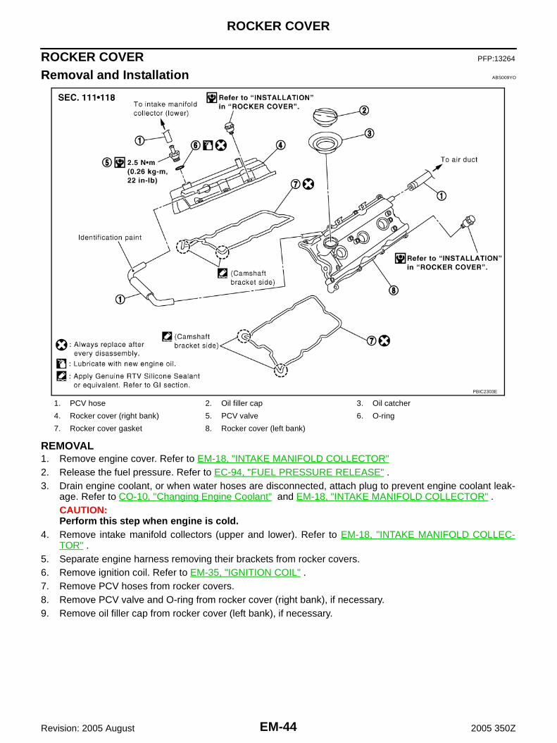
Removal and Installation ABS009YO
REMOVAL1. Remove engine cover. Refer to EM-18, "INTAKE MANIFOLD COLLECTOR"2. Release the fuel pressure. Refer to EC-94, "FUEL PRESSURE RELEASE" .3. Drain engine coolant, or when water hoses are disconnected, attach plug to prevent engine coolant leak-
age. Refer to CO-10, "Changing Engine Coolant" and EM-18, "INTAKE MANIFOLD COLLECTOR" .CAUTION:Perform this step when engine is cold.
4. Remove intake manifold collectors (upper and lower). Refer to EM-18, "INTAKE MANIFOLD COLLEC-TOR" .
5. Separate engine harness removing their brackets from rocker covers.6. Remove ignition coil. Refer to EM-35, "IGNITION COIL" .7. Remove PCV hoses from rocker covers.8. Remove PCV valve and O-ring from rocker cover (right bank), if necessary.9. Remove oil filler cap from rocker cover (left bank), if necessary.
1. PCV hose 2. Oil filler cap 3. Oil catcher
4. Rocker cover (right bank) 5. PCV valve 6. O-ring
7. Rocker cover gasket 8. Rocker cover (left bank)
PBIC2303E

ROCKER COVER
EM-45
C
D
E
F
G
H
I
J
K
L
M
A
EM
Revision: 2005 August 2005 350Z
10. Loosen mounting bolts with power tool in reverse order asshown in the figure.
11. Remove rocker cover gaskets from rocker covers.12. Use scraper to remove all trances of liquid gasket from cylinder head and camshaft bracket (No. 1).
CAUTION:Do not scratch or damage the mating surface when cleaning off old liquid gasket.
INSTALLATION1. Apply liquid gasket with tube presser [SST: WS39930000 ( —
)] to joint part among rocker cover, cylinder head and cam-shaft bracket (No. 1) as follows:Use Genuine RTV Silicone Sealant or equivalent. Refer toGI-47, "RECOMMENDED CHEMICAL PRODUCTS ANDSEALANTS" .NOTE:The figure shows an example of left bank side [zoomed inshows camshaft bracket (No. 1)].
a. Refer to the figure “a” to apply liquid gasket to joint part of cam-shaft bracket (No. 1) and cylinder head.
b. Refer to the figure “b” to apply liquid gasket to the figure “a”squarely.
2. Install new rocker cover gasket to rocker cover.3. Install rocker cover.
● Check if rocker cover gasket is not dropped from installation groove of rocker cover.
KBIA0985E
PBIC2474E
EM-46
ROCKER COVER
Revision: 2005 August 2005 350Z
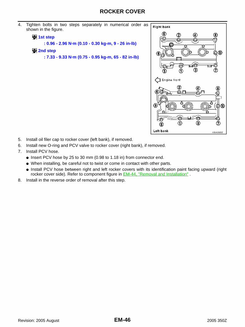
4. Tighten bolts in two steps separately in numerical order asshown in the figure.
5. Install oil filer cap to rocker cover (left bank), if removed.6. Install new O-ring and PCV valve to rocker cover (right bank), if removed.7. Install PCV hose.
● Insert PCV hose by 25 to 30 mm (0.98 to 1.18 in) from connector end.● When installing, be careful not to twist or come in contact with other parts.● Install PCV hose between right and left rocker covers with its identification paint facing upward (right
rocker cover side). Refer to component figure in EM-44, "Removal and Installation" .8. Install in the reverse order of removal after this step.
1st step: 0.96 - 2.96 N·m (0.10 - 0.30 kg-m, 9 - 26 in-lb)
2nd step: 7.33 - 9.33 N·m (0.75 - 0.95 kg-m, 65 - 82 in-lb)
KBIA0985E

FRONT TIMING CHAIN CASE
EM-47
C
D
E
F
G
H
I
J
K
L
M
A
EM
Revision: 2005 August 2005 350Z
FRONT TIMING CHAIN CASE PFP:13599
Removal and Installation ABS009YP
NOTE:● This section describes removal/installation procedure of front timing chain case and timing chain related
parts without removing oil pan (upper) on vehicle.● When oil pan (upper) needs to be removed or installed, or when rear timing chain case is removed or
installed, remove oil pans (upper and lower) first. Then remove front timing chain case, timing chainrelated parts, and rear timing chain case in this order, and install in the reverse order of removal. Refer toEM-59, "TIMING CHAIN" .
● Refer to EM-59, "TIMING CHAIN" for component parts location.
● To identify 35th Anniversary, refer to GI-52, "Application Item" .
REMOVAL1. Remove engine cover with power tool. Refer to EM-18, "INTAKE MANIFOLD COLLECTOR" .2. Remove undercover with power tool.3. Release the fuel pressure. Refer to EC-94, "FUEL PRESSURE RELEASE" .4. Disconnect the battery cable from the negative terminal.5. Drain engine oil. Refer to LU-10, "Changing Engine Oil" .
CAUTION:● Perform this step when engine is cold.● Do not spill engine oil on drive belts.
6. Drain engine coolant from radiator. Refer to CO-10, "Changing Engine Coolant" .CAUTION:● Perform this step when engine is cold.● Do not spill engine coolant on drive belts.
7. Remove radiator cooling fan assembly. Refer to CO-21, "COOLING FAN" .8. Separate engine harnesses removing their brackets from front timing chain case.9. Remove drive belts. Refer to EM-14, "DRIVE BELTS" .10. Remove power steering oil pump from bracket with piping connected, and temporarily secure it to aside.
Refer to PS-29, "POWER STEERING OIL PUMP" .11. Remove power steering oil pump bracket. Refer to PS-29, "POWER STEERING OIL PUMP" .12. Remove alternator. Refer to SC-21, "CHARGING SYSTEM" .13. Remove water bypass hose, water hose clamp and idler pulley bracket from front timing chain case.
14. Remove right and left intake valve timing control covers. (Except for 35th Anniversary)● Loosen mounting bolts in reverse order as shown in the fig-
ure.● Use seal cutter [SST: KV10111100 (J37228)] to cut liquid gas-
ket for removal.CAUTION:Shaft is internally jointed with camshaft sprocket (INT) cen-ter hole. When removing, keep it horizontal until it is com-pletely disconnected.
15. Remove left and right valve timing control covers (including magnet retarder and cover) with the followingprocedure. (For 35th Anniversary)
SEM728G

EM-48
FRONT TIMING CHAIN CASE
Revision: 2005 August 2005 350Z
a. Loosen mounting bolts in reverse order as shown in the figure.
b. Shaft is engaged with intake side camshaft sprocket center holeon inside. Pull straight out so as not to tilt until the joint is disen-gaged.● The mating surface of magnet retarder may be fitted with the
exhaust side camshaft sprocket via the engine oil. Open valvetiming control cover carefully.
● If the mating surface of magnet retarder is fitted with the cam-shaft sprocket, open the cover within the range that the load isnot applied to the harness. And then, remove it so as to pre-vent magnet retarder from dropping.
CAUTION:● Be careful not to damage magnet retarder.● When carrying valve timing control cover, face the magnet retarder side up to prevent the cover
from falling from magnet retarder.● Do not remove magnet retarder from valve timing control cover. (Disassembly prohibited parts)
16. Remove collared O-ring from front timing chain case (left andright side). (Only models except for 35th Anniversary)
17. Remove rocker covers (right and left banks). Refer to EM-44, "ROCKER COVER" .NOTE:When only timing chain (primary) is removed, rocker cover does not need to be removed.
18. Obtain No. 1 cylinder at TDC of its compression stroke as follows:NOTE:When timing chain is not removed/installed, this step is not required.
a. Rotate crankshaft pulley clockwise to align timing mark (groovedline without color) with timing indicator.
PBIC3560E
PBIC3561E
PBIC2631E
KBIA1717J

FRONT TIMING CHAIN CASE
EM-49
C
D
E
F
G
H
I
J
K
L
M
A
EM
Revision: 2005 August 2005 350Z
b. Make sure that intake and exhaust cam noses on No. 1 cylinder(engine front side of right bank) are located as shown in the fig-ure.● If not, turn crankshaft one revolution (360 degrees) and align
as shown in the figure.NOTE:When only timing chain (primary) is removed, rocker cover doesnot need to be removed. To make sure that No. 1 cylinder is atits compression TDC, remove front timing chain case first. Thencheck mating marks on camshaft sprockets. Refer to EM-69,"INSTALLATION" (Except for 35th Anniversary) or EM-90,"INSTALLATION" (For 35th Anniversary).
19. Remove crankshaft pulley as follows:a. Remove starter motor and set ring gear stopper [SST] as shown
in the figure. Refer to SC-10, "STARTING SYSTEM" .
b. Loosen crankshaft pulley bolt and locate bolt seating surface as10 mm (0.39 in) from its original position.CAUTION:Do not remove crankshaft pulley bolt as it will be used as asupporting point for suitable puller.
c. Place suitable puller tab on holes of crankshaft pulley, and pullcrankshaft pulley through.CAUTION:Do not put suitable puller tab on crankshaft pulley periph-ery, as this will damage internal damper.
20. Remove oil pan (lower). Refer to EM-29, "OIL PAN AND OIL STRAINER" .
SEM418G
PBIC1098E
PBIC1103E
EMQ0477D

EM-50
FRONT TIMING CHAIN CASE
Revision: 2005 August 2005 350Z
21. Loosen two mounting bolts in front of oil pan (upper) in reverseorder as shown in the figure.
22. Remove front timing chain case as follows:a. Loosen mounting bolts in reverse order as shown in the figure.
NOTE:Figure shows models except for 35th Anniversary.
b. Insert suitable tool into the notch at the top of the front timingchain case as shown (1).
c. Pry off case by moving tool as shown (2).● Use seal cutter [SST: KV10111100 (J37228)] to cut liquid gas-
ket for removal.CAUTION:● Do not use screwdriver or something similar.● After removal, handle front timing chain case carefully so
it does not tilt, cant, or warp under a load.
23. Remove O-rings from rear timing chain case.NOTE:Figure shows models except for 35th Anniversary.
24. Remove oil pan gasket. Refer to EM-29, "OIL PAN AND OIL STRAINER" .25. Remove water pump cover and chain tensioner cover from front timing chain case.
● Use seal cutter [SST: KV10111100 (J37228)] or equivalent tool to cut liquid gasket for removal.
PBIC1116E
KBIA1303E
SEM156F
PBIC2548E

FRONT TIMING CHAIN CASE
EM-51
C
D
E
F
G
H
I
J
K
L
M
A
EM
Revision: 2005 August 2005 350Z
26. Remove front oil seal from front timing chain case using suitabletool.● Use screwdriver for removal.CAUTION:Be careful not to damage front timing chain case.
27. Remove timing chain and related parts. Refer to EM-59, "TIMING CHAIN" .28. Use scraper to remove all traces of old liquid gasket from front
and rear timing chain cases and oil pan (upper), and liquid gas-ket mating surfaces.CAUTION:Be careful not to allow gasket fragments to enter oil pan.
● Remove old liquid gasket from bolt hole and thread.
INSTALLATION1. Install timing chain and related parts. Refer to EM-59, "TIMING CHAIN" .2. Hammer dowel pins (right and left) into front timing chain case
up to a point close to taper in order to shorten protrusion length.
3. Install new front oil seal on the front timing chain case.● Apply new engine oil to both oil seal lip and dust seal lip.
EMQ0032D
PBIC3492E
PBIC2084E
PBIC2615E

EM-52
FRONT TIMING CHAIN CASE
Revision: 2005 August 2005 350Z
● Install it so that each seal lip is oriented as shown in the fig-ure.
● Using suitable drift [outer diameter: 60 mm (2.36 in)], press-fitoil seal until it becomes flush with front timing chain case endface.
● Make sure the garter spring is in position and seal lip is notinverted.
4. Install water pump cover and chain tensioner cover to front timing chain case.● Apply a continuous bead of liquid gasket with tube presser
[SST: WS39930000 ( — )] to front timing chain case asshown in the figure.Use Genuine RTV Silicone Sealant or equivalent. Refer toGI-47, "RECOMMENDED CHEMICAL PRODUCTS ANDSEALANTS" .
5. Install front timing chain case as follows:
SEM715A
PBIC0790E
SEM744GA

FRONT TIMING CHAIN CASE
EM-53
C
D
E
F
G
H
I
J
K
L
M
A
EM
Revision: 2005 August 2005 350Z
a. Apply a continuous bead of liquid gasket with tube presser [SST:WS39930000 ( — )] to front timing chain case back side asshown in the figure.Use Genuine RTV Silicone Sealant or equivalent. Refer toGI-47, "RECOMMENDED CHEMICAL PRODUCTS ANDSEALANTS" .NOTE:Figure shows models except for 35th Anniversary.
b. Install new oil pan gasket.● Apply liquid gasket to oil pan gasket as shown in the figure.
Use Genuine RTV Silicone Sealant or equivalent. Refer toGI-47, "RECOMMENDED CHEMICAL PRODUCTS ANDSEALANTS" .
● Align notch of front timing chain case with protrusion of oil pangasket.
PBIC2658E
PBIC2630E
PBIC1114E

EM-54
FRONT TIMING CHAIN CASE
Revision: 2005 August 2005 350Z
● Apply liquid gasket with tube presser [SST: WS39930000( — )] to top surface of oil pan (upper) as shown in the fig-ure.Use Genuine RTV Silicone Sealant or equivalent. Refer toGI-47, "RECOMMENDED CHEMICAL PRODUCTS ANDSEALANTS" .
c. Install new O-rings on rear timing chain case.NOTE:Figure shows models except for 35th Anniversary.
d. Assemble front timing chain case as follows:i. Fit lower end of front timing chain case tightly onto top face of oil
pan (upper). From the fitting point, make entire front timing chaincase contact rear timing chain case completely.CAUTION:Be careful that oil pan gasket is in place.
ii. Since front timing chain case is offset for difference of bolt holes,tight bolts temporarily with holding front timing chain case fromfront and top as shown in the figure.
iii. Same as the step ii, insert dowel pin with holding front timingchain case from front and top completely.
PBIC1099E
PBIC2548E
PBIC1100E
PBIC1115E
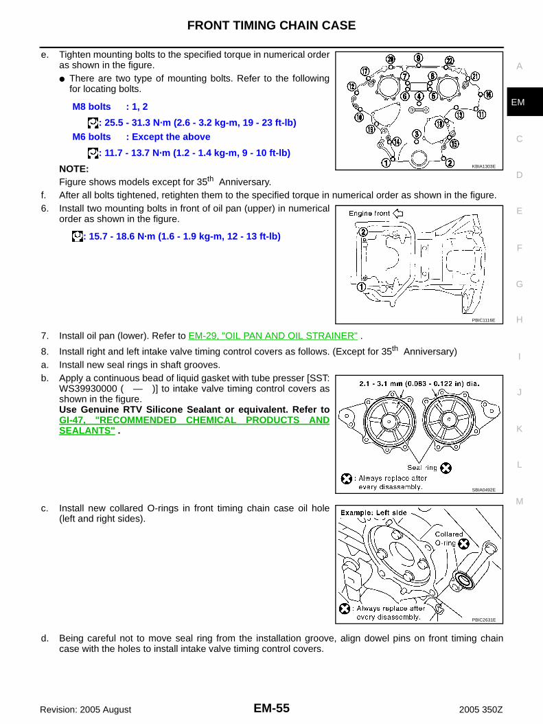
FRONT TIMING CHAIN CASE
EM-55
C
D
E
F
G
H
I
J
K
L
M
A
EM
Revision: 2005 August 2005 350Z
e. Tighten mounting bolts to the specified torque in numerical orderas shown in the figure.● There are two type of mounting bolts. Refer to the following
for locating bolts.
NOTE:Figure shows models except for 35th Anniversary.
f. After all bolts tightened, retighten them to the specified torque in numerical order as shown in the figure.6. Install two mounting bolts in front of oil pan (upper) in numerical
order as shown in the figure.
7. Install oil pan (lower). Refer to EM-29, "OIL PAN AND OIL STRAINER" .
8. Install right and left intake valve timing control covers as follows. (Except for 35th Anniversary)a. Install new seal rings in shaft grooves.b. Apply a continuous bead of liquid gasket with tube presser [SST:
WS39930000 ( — )] to intake valve timing control covers asshown in the figure.Use Genuine RTV Silicone Sealant or equivalent. Refer toGI-47, "RECOMMENDED CHEMICAL PRODUCTS ANDSEALANTS" .
c. Install new collared O-rings in front timing chain case oil hole(left and right sides).
d. Being careful not to move seal ring from the installation groove, align dowel pins on front timing chaincase with the holes to install intake valve timing control covers.
M8 bolts : 1, 2
: 25.5 - 31.3 N·m (2.6 - 3.2 kg-m, 19 - 23 ft-lb)M6 bolts : Except the above
: 11.7 - 13.7 N·m (1.2 - 1.4 kg-m, 9 - 10 ft-lb)
: 15.7 - 18.6 N·m (1.6 - 1.9 kg-m, 12 - 13 ft-lb)
KBIA1303E
PBIC1116E
SBIA0492E
PBIC2631E

EM-56
FRONT TIMING CHAIN CASE
Revision: 2005 August 2005 350Z
e. Tighten mounting bolts in numerical order as shown in the fig-ure.
9. Install right and left valve timing control covers as follows. (For 35th Anniversary)a. Install new seal rings in shaft grooves.
b. Install magnet retarder aligning the dowel pins of the back withthe cover side dowel pin holes securely. Simultaneously insertthe harness into the installation groove securely.NOTE:Figure shows the structure of the parts. Therefore, magnetretarder is being removed from the cover in this figure. But, ifmagnet retarder is in the correct position, omit step “b” and per-form step “c”.
c. To check the joint between dowel pins and dowel pin holes,check the looseness in the axle direction by pushing the matingsurface of magnet retarder at several places and the circumfer-ential looseness (between dowel pins and dowel pin holes) bytwisting in the circumferential direction.CAUTION:Always perform this procedure when removing because thegap between dowel pins and dowel pin holes may not becaused on purpose.
PBIC0918E
PBIC3571E
PBIC3572E
PBIC3573E

FRONT TIMING CHAIN CASE
EM-57
C
D
E
F
G
H
I
J
K
L
M
A
EM
Revision: 2005 August 2005 350Z
d. Install valve timing control cover to front timing chain case.CAUTION:● Do not face the magnet retarder side down to prevent
magnet retarder from dropping.● Check the mating surface of magnet retarder and the
drum of exhaust side camshaft sprocket for foreign mate-rials.
● Align the center of both shaft holes of the shaft and theintake side camshaft sprocket, and then insert them.
● Be careful not to drop the seal ring from the shaft groove.● When setting the valve timing control cover in position
by hand, if valve timing control cover is not contacting with the front timing chain case, thedowel pin of magnet retarder may not be aligned with the dowel pin holes of cover. In this case,return to step “b”.
e. Tighten mounting bolts in numerical order as shown in the fig-ure.CAUTION:Completely tighten the mounting bolts with the seat surfaceof valve timing control cover contacting with front timingchain case.
10. Install crankshaft pulley as follows:a. Fix crankshaft using ring gear stopper [SST: KV10117700 (J44716)].b. Install crankshaft pulley, taking care not to damage front oil seal.
● When press-fitting crankshaft pulley with plastic hammer, tap on its center portion (not circumference).
c. Tighten crankshaft pulley bolt.
d. Turn crankshaft pulley bolt 84 to 90 degrees clockwise [Target:90 degrees (angle tightening)].CAUTION:Check the tightening angle by using the angle wrench[SST]. Avoid judgement by visual inspection without SST.● Check tightening angle indicated on the angle wrench indica-
tor plate.
11. Rotate crankshaft pulley in normal direction (clockwise when viewed from front) to confirm it turnssmoothly.
12. Install in the reverse order of removal after this step.
INSPECTION AFTER INSTALLATIONInspection for LeaksThe following are procedures for checking fluid leak, lubricates leak and exhaust gases leak.● Before starting engine, check oil/fluid levels including engine coolant and engine oil. If less than required
quantity, fill to the specified level. Refer to MA-12, "RECOMMENDED FLUIDS AND LUBRICANTS" .● Run engine to check for unusual noise and vibration.
PBIC3561E
PBIC3560E
: 39.2 - 49.0 N·m (4.0 - 5.0 kg-m, 29 - 36 ft-lb)
PBIC3821E

EM-58
FRONT TIMING CHAIN CASE
Revision: 2005 August 2005 350Z
NOTE:If hydraulic pressure inside timing chain tensioner drops after removal/installation, slack in the guide maygenerate a pounding noise during and just after engine start. However, this is normal. Noise will stop afterhydraulic pressure rises.
● Warm up engine thoroughly to make sure there is no leakage of exhaust gases, or any oil/fluids includingengine oil and engine coolant.
● Bleed air from lines and hoses of applicable lines, such as in cooling system.● After cooling down engine, again check oil/fluid levels including engine oil and engine coolant. Refill to the
specified level, if necessary.
Summary of the inspection items:
* Transmission/transaxle/CVT fluid, power steering fluid, brake fluid, etc.
Item Before starting engine Engine running After engine stopped
Engine coolant Level Leakage Level
Engine oil Level Leakage Level
Other oils and fluid* Level Leakage Level

TIMING CHAIN
EM-59
C
D
E
F
G
H
I
J
K
L
M
A
EM
Revision: 2005 August 2005 350Z
TIMING CHAIN PFP:13028
Removal and Installation (Except for 35th Anniversary) ABS009YQ
NOTE:To identify 35th Anniversary, refer to GI-52, "Application Item" .
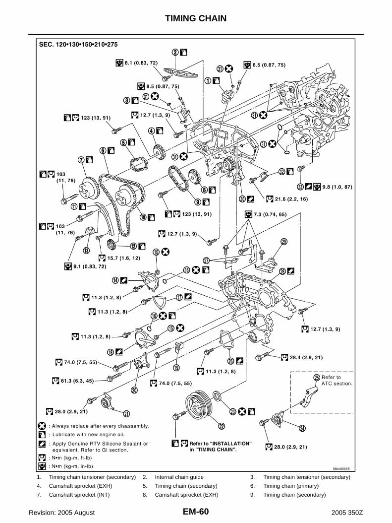
EM-60
TIMING CHAIN
Revision: 2005 August 2005 350Z
1. Timing chain tensioner (secondary) 2. Internal chain guide 3. Timing chain tensioner (secondary)
4. Camshaft sprocket (EXH) 5. Timing chain (secondary) 6. Timing chain (primary)
7. Camshaft sprocket (INT) 8. Camshaft sprocket (EXH) 9. Timing chain (secondary)
SBIA0588E

TIMING CHAIN
EM-61
C
D
E
F
G
H
I
J
K
L
M
A
EM
Revision: 2005 August 2005 350Z
NOTE:● This section describes procedures for removing/installing front timing chain case and timing chain related
parts, and rear timing chain case, when oil pan (upper) needs to be removed/installed for engine overhaul,etc.
● To remove/install front timing chain case, timing chain, and its related parts without removing oil pan(upper), refer to EM-47, "FRONT TIMING CHAIN CASE" .
REMOVAL1. Remove engine cover with power tool. Refer to EM-18, "INTAKE MANIFOLD COLLECTOR" .2. Remove air cleaner case assembly. Refer to EM-16, "AIR CLEANER AND AIR DUCT" .3. Remove undercover with power tool.4. Release the fuel pressure. Refer to EC-94, "FUEL PRESSURE RELEASE" .5. Disconnect the battery cable from the negative terminal.6. Drain engine coolant from radiator. Refer to CO-10, "Changing Engine Coolant" .
CAUTION:● Perform this step when engine is cold.● Do not spill engine coolant on drive belts.
7. Drain engine oil. Refer to LU-10, "Changing Engine Oil" .CAUTION:● Perform this step when engine is cold.● Do not spill engine oil on drive belts.
8. Separate engine harnesses removing their brackets from front timing chain case.9. Remove intake manifold collectors (upper and lower). Refer to EM-18, "INTAKE MANIFOLD COLLEC-
TOR" .10. Remove radiator cooling fan assembly. Refer to CO-21, "COOLING FAN" .11. Remove drive belts. Refer to EM-14, "DRIVE BELTS" .12. Remove A/C compressor from bracket with piping connected, and temporarily secure it aside. Refer to
ATC-129, "Components" .13. Remove power steering oil pump from bracket with piping connected, and temporarily secure it aside.
Refer to PS-29, "POWER STEERING OIL PUMP" .14. Remove power steering oil pump bracket. Refer to PS-29, "POWER STEERING OIL PUMP" .15. Remove alternator. Refer to SC-21, "CHARGING SYSTEM" .16. Remove water bypass hose, water hose clamp and idler pulley bracket from front timing chain case.17. Remove right and left intake valve timing control covers.
● Loosen mounting bolts in reverse order as shown in the fig-ure.
● Use seal cutter [SST: KV10111100 (J37228)] to cut liquid gas-ket for removal.
CAUTION:Shaft is internally jointed with camshaft sprocket (INT) cen-ter hole. When removing, keep it horizontal until it is com-pletely disconnected.
10. Camshaft sprocket (INT) 11. Slack guide 12. Crankshaft sprocket
13. Timing chain tensioner (primary) 14. Intake valve timing control cover 15. Collared O-ring
16. Seal ring 17. Chain tensioner cover 18. Intake valve timing control cover
19. Water hose clamp 20. Idler pulley bracket 21. Idler pulley
22. Crankshaft pulley 23. Front oil seal 24. Idler pulley
25. A/C compressor bracket 26. Water pump cover 27. Bracket
28. Front timing chain case 29. Bracket 30. Rear timing chain case
31. O-ring 32. Tension guide 33. Water drain plug (Front)
SEM728G

EM-62
TIMING CHAIN
Revision: 2005 August 2005 350Z
18. Remove collared O-ring from front timing chain case (left andright side).
19. Remove rocker covers (right and left banks). Refer to EM-44, "ROCKER COVER" .20. Obtain No. 1 cylinder at TDC of its compression stroke as follows:a. Rotate crankshaft pulley clockwise to align timing mark (grooved
line without color) with timing indicator.
b. Make sure that intake and exhaust cam noses on No. 1 cylinder(engine front side of right bank) are located as shown in the fig-ure.● If not, turn crankshaft one revolution (360 degrees) and align
as shown in the figure.
21. Remove crankshaft pulley as follows:a. Remove starter motor and set ring gear stopper [SST] as shown
in the figure. Refer to SC-10, "STARTING SYSTEM" .
PBIC2631E
KBIA1717J
SEM418G
PBIC1098E

TIMING CHAIN
EM-63
C
D
E
F
G
H
I
J
K
L
M
A
EM
Revision: 2005 August 2005 350Z
b. Loosen crankshaft pulley bolt and rotate bolt seating surface at10 mm (0.39 in) from its original position.CAUTION:Do not remove crankshaft pulley bolt as it will be used as asupporting point for suitable puller.
c. Place suitable puller tab on holes of crankshaft pulley, and pullcrankshaft pulley through.CAUTION:Do not put suitable puller tab on crankshaft pulley periph-ery, as this will damage internal damper.
22. Remove oil pans (upper and lower). Refer to EM-29, "OIL PAN AND OIL STRAINER" .23. Remove front timing chain case as follows:a. Loosen mounting bolts in reverse order as shown in the figure.
b. Insert suitable tool into the notch at the top of the front timingchain case as shown (1).
c. Pry off case by moving the tool as shown (2).● Use seal cutter [SST: KV10111100 (J37228)] to cut liquid gas-
ket for removal. CAUTION:● Do not use screwdriver or something similar.● After removal, handle front timing chain case carefully so
it does not tilt, cant, or warp under a load.
PBIC1103E
EMQ0477D
KBIA1303E
SEM156F
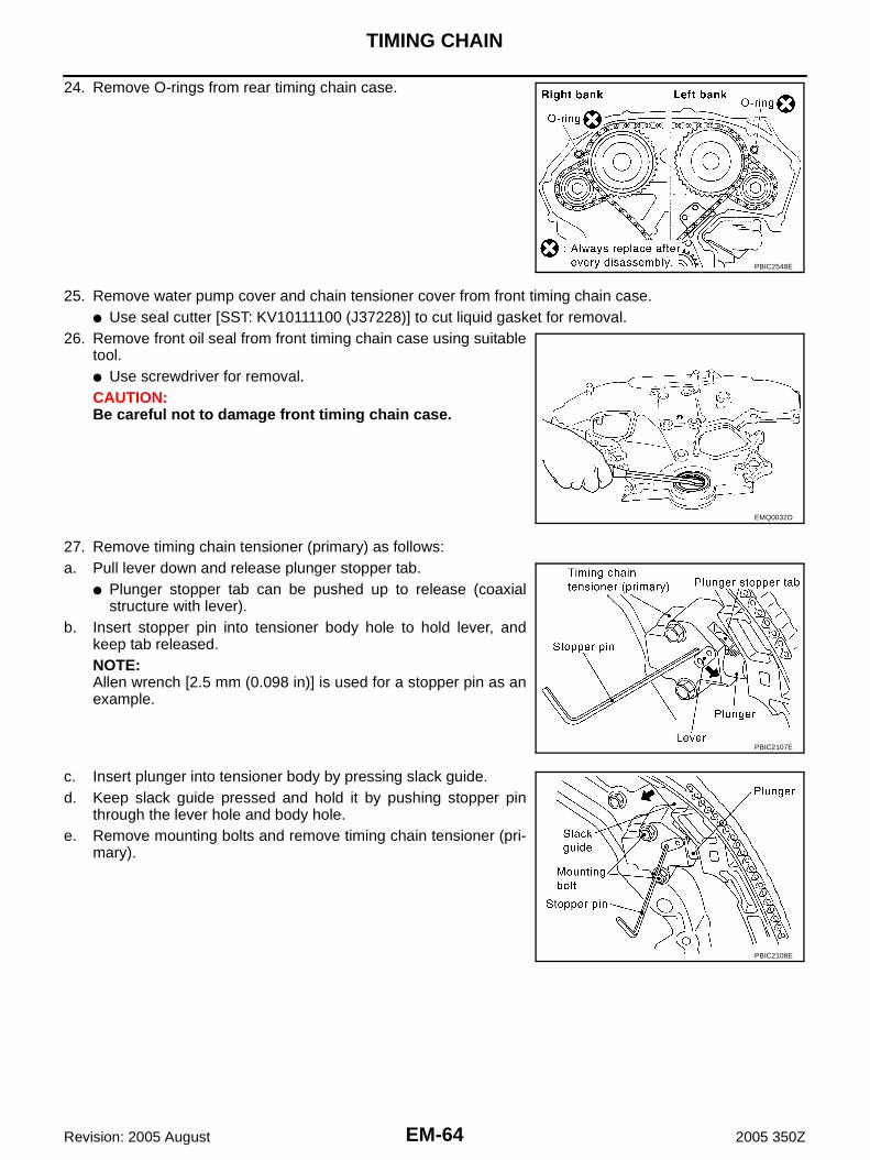
EM-64
TIMING CHAIN
Revision: 2005 August 2005 350Z
24. Remove O-rings from rear timing chain case.
25. Remove water pump cover and chain tensioner cover from front timing chain case. ● Use seal cutter [SST: KV10111100 (J37228)] to cut liquid gasket for removal.
26. Remove front oil seal from front timing chain case using suitabletool.● Use screwdriver for removal.CAUTION:Be careful not to damage front timing chain case.
27. Remove timing chain tensioner (primary) as follows:a. Pull lever down and release plunger stopper tab.
● Plunger stopper tab can be pushed up to release (coaxialstructure with lever).
b. Insert stopper pin into tensioner body hole to hold lever, andkeep tab released.NOTE:Allen wrench [2.5 mm (0.098 in)] is used for a stopper pin as anexample.
c. Insert plunger into tensioner body by pressing slack guide.d. Keep slack guide pressed and hold it by pushing stopper pin
through the lever hole and body hole.e. Remove mounting bolts and remove timing chain tensioner (pri-
mary).
PBIC2548E
EMQ0032D
PBIC2107E
PBIC2108E

TIMING CHAIN
EM-65
C
D
E
F
G
H
I
J
K
L
M
A
EM
Revision: 2005 August 2005 350Z
28. Remove internal chain guide, tension guide and slack guide.NOTE:Tension guide can be removed after removing timing chain (pri-mary).
29. Remove timing chain (primary) and crankshaft sprocket.CAUTION:After removing timing chain (primary), do not turn crankshaft and camshaft separately, or valveswill strike the piston heads.
30. Remove timing chain (secondary) and camshaft sprockets as follows:a. Attach suitable stopper pin to the right and left timing chain ten-
sioners (secondary).NOTE:● Use approximately 0.5 mm (0.02 in) dia. hard metal pin as a
stopper pin.● For removal of timing chain tensioner (secondary), refer to
EM-102, "CAMSHAFT" . [Removing camshaft bracket (No. 1)is required.]
b. Remove intake and exhaust camshaft sprocket bolts.● Secure the hexagonal portion of camshaft using wrench to
loosen mounting bolts.CAUTION:Do not loosen mounting bolts with securing anythingother than the camshaft hexagonal portion or with ten-sioning the timing chain.
c. Remove timing chain (secondary) together with camshaft sprockets.● Turn camshaft slightly to secure slackness of timing chain on timing chain tensioner (secondary) side.
PBIC2266E
PBIC2047E
KBIA1698J

EM-66
TIMING CHAIN
Revision: 2005 August 2005 350Z
● Insert 0.5 mm (0.020 in)-thick metal or resin plate betweentiming chain and timing chain tensioner plunger (guide).Remove timing chain (secondary) together with camshaftsprockets with timing chain loose from guide groove.CAUTION:Be careful of plunger coming-off when removing timingchain (secondary). This is because plunger of timingchain tensioner (secondary) moves during operation,leading to coming-off of fixed stopper pin. NOTE:Camshaft sprocket (INT) is two-for-one structure of primaryand secondary sprockets.
● When handling camshaft sprocket (INT), be careful of the fol-lowing caution:CAUTION:● Handle carefully to avoid any shock to camshaft
sprocket.● Do not disassemble. (Do not loosen bolts “A” as
shown in the figure).
31. Remove water pump. Refer to CO-23, "WATER PUMP" .32. Remove rear timing chain case as follows:a. Loosen and remove mounting bolts in reverse order as shown in
the figure.b. Cut liquid gasket using seal cutter [SST: KV10111100 (J37228)]
and remove rear timing chain case.
CAUTION:● Do not remove plate metal cover of oil passage.● After removal, handle rear timing chain case carefully so
it does not tilt, cant, or warp under a load.
PBIC1978E
PBIC2980E
SEM735G
KBIA1307E

TIMING CHAIN
EM-67
C
D
E
F
G
H
I
J
K
L
M
A
EM
Revision: 2005 August 2005 350Z
33. Remove O-rings from cylinder head.
34. Remove O-rings from cylinder block.
35. Remove timing chain tensioners (secondary) from cylinder head as follows, if necessary.a. Remove camshaft brackets (No. 1). Refer to EM-103, "REMOVAL" .b. Remove timing chain tensioners (secondary) with stopper pin attached.36. Use scraper to remove all traces of old liquid gasket from front
and rear timing chain cases, and opposite mating surfaces.
● Remove old liquid gasket from bolt hole and thread.
SBIA0496E
PBIC0788E
SEM737G
PBIC2084E

EM-68
TIMING CHAIN
Revision: 2005 August 2005 350Z
37. Use scraper to remove all traces of liquid gasket from waterpump cover, chain tensioner cover and intake valve timing con-trol covers.
INSPECTION AFTER REMOVALTiming ChainCheck for cracks and any excessive wear at link plates and rollerlinks of timing chain. Replace timing chain as necessary.
SEM926E
PBIC0282E

TIMING CHAIN
EM-69
C
D
E
F
G
H
I
J
K
L
M
A
EM
Revision: 2005 August 2005 350Z
INSTALLATIONNOTE:The below figure shows the relationship between the mating mark on each timing chain and that on the corre-sponding sprocket, with the components installed.
1. Install timing chain tensioners (secondary) to cylinder head as follows if removed. Refer to EM-107,"INSTALLATION" .
a. Install timing chain tensioners (secondary) with stopper pin attached and new O-ring.b. Install camshaft brackets (No. 1). Refer to EM-107, "INSTALLATION" .2. Install rear timing chain case as follows:a. Install new O-rings onto cylinder block.
PBIC1792E
PBIC0788E

EM-70
TIMING CHAIN
Revision: 2005 August 2005 350Z
b. Install new O-rings to cylinder head.
c. Apply liquid gasket with tube presser [SST: WS39930000 ( — )] to rear timing chain case back side asshown in the figure.Use Genuine RTV Silicone Sealant or equivalent. Refer to GI-47, "RECOMMENDED CHEMICALPRODUCTS AND SEALANTS" .CAUTION:● For “A” in the figure, completely wipe out liquid gasket extended on a portion touching at
engine coolant.
SBIA0496E

TIMING CHAIN
EM-71
C
D
E
F
G
H
I
J
K
L
M
A
EM
Revision: 2005 August 2005 350Z
● Apply liquid gasket on installation position of water pump and cylinder head very completely.
d. Align rear timing chain case and water pump assembly with dowel pins (right and left) on cylinder blockand install rear timing chain case.● Make sure O-rings stay in place during installation to cylinder block and cylinder head.
e. Tighten mounting bolts in numerical order as shown in the fig-ure.● There are two type mounting bolts. Refer to the following for
locating bolts.
Bolt length: Bolt position20 mm (0.79 in) : 1, 2, 3, 6, 7, 8, 9, 1016 mm (0.63 in) : Except the above
: 11.7 - 13.7 N·m (1.2 - 1.4 kg-m, 9 - 10 ft-lb)
PBIC2659E
SEM735G

EM-72
TIMING CHAIN
Revision: 2005 August 2005 350Z
f. After all bolts are tightened, retighten them to the specified in numerical order shown in the figure.● If liquid gasket protrudes, wipe it off immediately.
g. After installing rear timing chain case, check the surface heightdifference between following parts on oil pan (upper) mountingsurface.
● If not within standard, repeat the installation procedure.
3. Install water pump with new O-rings. Refer to CO-23, "WATER PUMP" .4. Make sure that dowel pin hole, dowel pin and crankshaft key are
located as shown in the figure. (No. 1 cylinder at compressionTDC)● NOTE:
Though camshaft does not stop at the position as shown inthe figure, for the placement of cam nose, it is generallyaccepted camshaft is placed for the same direction of the fig-ure.
CAUTION:Hole on small dia. side must be used for intake side dowel pin hole. Do not misidentify (ignore bigdia. side).
5. Install timing chains (secondary) and camshaft sprockets as follows:CAUTION:Mating marks between timing chain and sprockets slip easily. Confirm all mating mark positionsrepeatedly during the installation process.
a. Push plunger of timing chain tensioner (secondary) and keep itpressed in with stopper pin.
StandardRear timing chain case to cylinder block:
–0.24 to 0.14 mm (–0.0094 to 0.0055 in)
SEM943G
Camshaft dowel pin hole (intake side): At cylinder head upper face side in each bank.
Camshaft dowel pin (exhaust side): At cylinder head upper face side in each bank.
Crankshaft key: At cylinder head side of right bank.
KBIA1073E
SEM430G

TIMING CHAIN
EM-73
C
D
E
F
G
H
I
J
K
L
M
A
EM
Revision: 2005 August 2005 350Z
b. Install timing chains (secondary) and camshaft sprockets.● Align the mating marks on timing chain (secondary) (gold link)
with the ones on intake and exhaust camshaft sprockets(punched), and install them.NOTE:● Mating marks for intake camshaft sprocket are on the back
side of camshaft sprocket (secondary).● There are two types of mating marks, circle and oval types.
They should be used for the right and left banks, respec-tively.
● Align dowel pin and pin hole on camshafts with the grooveand dowel pin on sprockets, and install them.
● On the intake side, align pin hole on the small diameter side ofthe camshaft front end with dowel pin on the back side ofcamshaft sprocket, and install them.
● On the exhaust side, align dowel pin on camshaft front endwith pin groove on camshaft sprocket, and install them.
● In case that positions of each mating mark and each dowelpin are not fit on mating parts, make fine adjustment to theposition holding the hexagonal portion on camshaft with wrench or equivalent.
● Mounting bolts for camshaft sprockets must be tightened in the next step. Tightening them by hand isenough to prevent the dislocation of dowel pins.
● It may be difficult to visually check the dislocation of matingmarks during and after installation. To make the matchingeasier, make a mating mark on the top of sprocket teeth andits extended line in advance with paint.
c. After confirming the mating marks are aligned, tighten camshaftsprocket mounting bolts.● Secure camshaft using wrench at the hexagonal portion to
tighten mounting bolts.
Right bank : Use circle type.Left bank : Use oval type.
PBIC2981E
PBIC0891E
KBIA1698J

EM-74
TIMING CHAIN
Revision: 2005 August 2005 350Z
d. Pull stopper pins out from timing chain tensioners (secondary).
6. Install tension guide.7. Install timing chain (primary) as follows:a. Install crankshaft sprocket.
● Make sure the mating marks on crankshaft sprocket face thefront of engine.
b. Install timing chain (primary).● Install timing chain (primary) so the mating mark (punched) on
camshaft sprocket is aligned with the yellow link on timingchain, while the mating mark (notched) on crankshaftsprocket is aligned with the orange one on timing chain, asshown in the figure.
● When it is difficult to align mating marks of timing chain (pri-mary) with each sprocket, gradually turn camshaft usingwrench on the hexagonal portion to align it with the matingmarks.
● During alignment, be careful to prevent dislocation of matingmark alignments of timing chains (secondary).
PBIC2110E
SEM929E
PBIC2632E
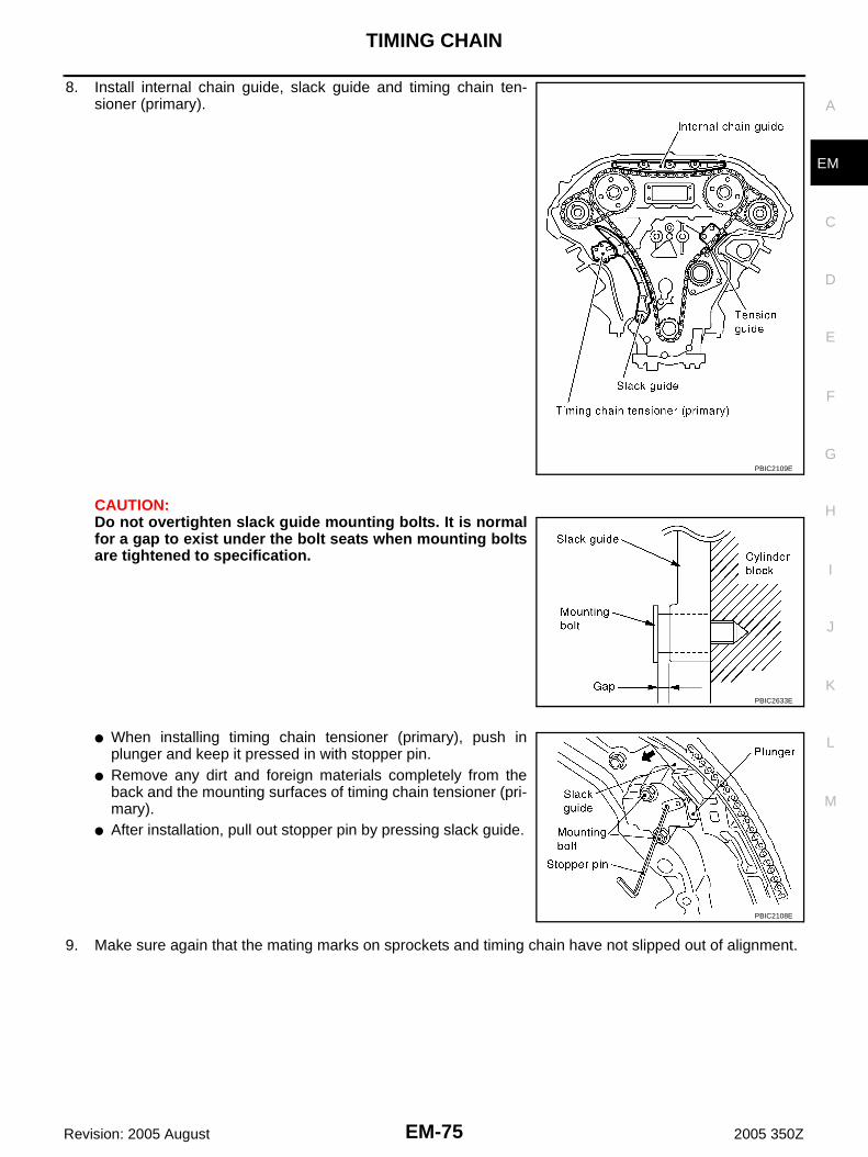
TIMING CHAIN
EM-75
C
D
E
F
G
H
I
J
K
L
M
A
EM
Revision: 2005 August 2005 350Z
8. Install internal chain guide, slack guide and timing chain ten-sioner (primary).
CAUTION:Do not overtighten slack guide mounting bolts. It is normalfor a gap to exist under the bolt seats when mounting boltsare tightened to specification.
● When installing timing chain tensioner (primary), push inplunger and keep it pressed in with stopper pin.
● Remove any dirt and foreign materials completely from theback and the mounting surfaces of timing chain tensioner (pri-mary).
● After installation, pull out stopper pin by pressing slack guide.
9. Make sure again that the mating marks on sprockets and timing chain have not slipped out of alignment.
PBIC2109E
PBIC2633E
PBIC2108E

EM-76
TIMING CHAIN
Revision: 2005 August 2005 350Z
10. Install new O-rings on rear timing chain case.
11. Install new front oil seal on front timing chain case.● Apply new engine oil to both oil seal lip and dust seal lip.● Install it so that each seal lip is oriented as shown in the fig-
ure.
● Using suitable drift, press-fit oil seal until it becomes flush withfront timing chain case end face.
● Make sure the garter spring is in position and seal lip is notinverted.
12. Install water pump cover and chain tensioner cover to front timing chain case.● Apply a continuous bead of liquid gasket with tube presser
[SST: WS39930000 ( — )] to front timing chain case asshown in the figure.Use Genuine RTV Silicone Sealant or equivalent. Refer toGI-47, "RECOMMENDED CHEMICAL PRODUCTS ANDSEALANTS" .
13. Install front timing chain case as follows:
PBIC2548E
SEM715A
PBIC0790E
SEM744GA

TIMING CHAIN
EM-77
C
D
E
F
G
H
I
J
K
L
M
A
EM
Revision: 2005 August 2005 350Z
a. Apply a continuous bead of liquid gasket with tube presser [SST:WS39930000 ( — )] to front timing chain case back side asshown in the figure.Use Genuine RTV Silicone Sealant or equivalent. Refer toGI-47, "RECOMMENDED CHEMICAL PRODUCTS ANDSEALANTS" .
b. Install front timing chain case as to fit its dowel pin hole together dowel pin on rear timing chain case.c. Tighten mounting bolts to the specified torque in numerical order
as shown in the figure.● There are two type of mounting bolts. Refer to the following
for locating bolts.
d. After all bolts are tightened, retighten them to the specifiedtorque in numerical order shown in the figure.CAUTION:Be sure to wipe off any excessive liquid gasket leaking on surface mating with oil pan (upper).
e. After installing front timing chain case, check the surface heightdifference between the following parts on the oil pan (upper)mounting surface.
● If not within standard, repeat the installation procedure.
14. Install right and left intake valve timing control covers as follows:a. Install new seal rings in shaft grooves.
PBIC2658E
M8 bolts : 1, 2
: 25.5 - 31.3 N·m (2.6 - 3.2 kg-m, 19 - 23 ft-lb)M6 bolts : Except the above
: 11.7 - 13.7 N·m (1.2 - 1.4 kg-m, 9 - 10 ft-lb)
StandardFront timing chain case to rear timing chain case:
–0.14 to 0.14 mm (–0.005 to 0.0055 in)
KBIA1303E
SEM943G

EM-78
TIMING CHAIN
Revision: 2005 August 2005 350Z
b. Apply a continuous bead of liquid gasket with tube presser [SST:WS39930000 ( — )] to intake valve timing control covers asshown in the figure.Use Genuine RTV Silicone Sealant or equivalent. Refer toGI-47, "RECOMMENDED CHEMICAL PRODUCTS ANDSEALANTS" .
c. Install new collared O-rings in front timing chain case oil hole(left and right sides).
d. Being careful not to move seal ring from the installation groove, align dowel pins on front timing chaincase with holes to install intake valve timing control covers.
e. Tighten mounting bolts in numerical order as shown in the fig-ure.
15. Install oil pans (upper and lower). Refer to EM-29, "OIL PAN AND OIL STRAINER" .16. Install rocker covers (right and left banks). Refer to EM-44, "ROCKER COVER" .17. Install crankshaft pulley as follows:a. Fix crankshaft using ring gear stopper [SST: KV10117700 (J44716)].b. Install crankshaft pulley, taking care not to damage front oil seal.
● When press-fitting crankshaft pulley with plastic hammer, tap on its center portion (not circumference).c. Tighten crankshaft pulley bolt.
SBIA0492E
PBIC2631E
PBIC0918E
: 39.2 - 49.0 N·m (4.0 - 5.0 kg-m, 29 - 36 ft-lb)

TIMING CHAIN
EM-79
C
D
E
F
G
H
I
J
K
L
M
A
EM
Revision: 2005 August 2005 350Z
d. Turn crankshaft pulley bolt 84 to 90 degrees clockwise [Target:90 degrees (angle tightening)].CAUTION:Check the tightening angle by using the angle wrench[SST]. Avoid judgement by visual inspection without SST.● Check tightening angle indicated on the angle wrench indica-
tor plate.
18. Rotate crankshaft pulley in normal direction (clockwise when viewed from engine front) to confirm it turnssmoothly.
19. Install in the reverse order of removal after this step.NOTE:If hydraulic pressure inside timing chain tensioner drops after removal/installation, slack in guide may gen-erate a pounding noise during and just after engine start. However, this is normal. Noise will stop afterhydraulic pressure rises.
PBIC3821E

EM-80
TIMING CHAIN
Revision: 2005 August 2005 350Z
INSPECTION AFTER INSTALLATIONInspection for LeaksThe following are procedures for checking fluids leak, lubricates leak and exhaust gases leak.● Before starting engine, check oil/fluid levels including engine coolant and engine oil. If less than required
quantity, fill to the specified level. Refer to MA-12, "RECOMMENDED FLUIDS AND LUBRICANTS" .● Use procedure below to check for fuel leakage.– Turn ignition switch “ON” (with engine stopped). With fuel pressure applied to fuel piping, check for fuel
leakage at connection points.– Start engine. With engine speed increased, check again for fuel leakage at connection points.● Run engine to check for unusual noise and vibration.
NOTE:If hydraulic pressure inside timing chain tensioner drops after removal/installation, slack in the guide maygenerate a pounding noise during and just after engine start. However, this is normal. Noise will stop afterhydraulic pressure rises.
● Warm up engine thoroughly to make sure there is no leakage of fuel, exhaust gases, or any oil/fluidsincluding engine oil and engine coolant.
● Bleed air from lines and hoses of applicable lines, such as in cooling system.● After cooling down engine, again check oil/fluid levels including engine oil and engine coolant. Refill to the
specified level, if necessary.
Summary of the inspection items:
* Transmission/transaxle/CVT fluid, power steering fluid, brake fluid, etc.
Item Before starting engine Engine running After engine stopped
Engine coolant Level Leakage Level
Engine oil Level Leakage Level
Other oils and fluid* Level Leakage Level
Fuel Leakage Leakage Leakage
Exhaust gases — Leakage —

TIMING CHAIN
EM-81
C
D
E
F
G
H
I
J
K
L
M
A
EM
Revision: 2005 August 2005 350Z
Removal and Installation (For 35th Anniversary) ABS00FIP
NOTE:To identify 35th Anniversary, refer to GI-52, "Application Item" .
KBIA4372J

EM-82
TIMING CHAIN
Revision: 2005 August 2005 350Z
● Refer to GI-10, "Components" for symbol mark in the figure.NOTE:● This section describes procedures for removing/installing front timing chain case and timing chain related
parts, and rear timing chain case, when oil pan (upper) needs to be removed/installed for engine overhaul,etc.
● To remove/install front timing chain case, timing chain, and its related parts without removing oil pan(upper), refer to EM-47, "FRONT TIMING CHAIN CASE" .
REMOVAL1. Remove engine cover with power tool. Refer to EM-18, "INTAKE MANIFOLD COLLECTOR" .2. Remove air cleaner case assembly. Refer to EM-16, "AIR CLEANER AND AIR DUCT" .3. Remove undercover with power tool.4. Release the fuel pressure. Refer to EC-94, "FUEL PRESSURE RELEASE" .5. Disconnect the battery cable from the negative terminal.6. Drain engine coolant from radiator. Refer to CO-10, "Changing Engine Coolant" .
CAUTION:● Perform this step when engine is cold.● Do not spill engine coolant on drive belts.
7. Drain engine oil. Refer to LU-10, "Changing Engine Oil" .CAUTION:● Perform this step when engine is cold.● Do not spill engine oil on drive belts.
8. Separate engine harnesses removing their brackets from front timing chain case.9. Remove intake manifold collectors (upper and lower). Refer to EM-18, "INTAKE MANIFOLD COLLEC-
TOR" .10. Remove radiator cooling fan assembly. Refer to CO-21, "COOLING FAN" .11. Remove drive belts. Refer to EM-14, "DRIVE BELTS" .12. Remove A/C compressor from bracket with piping connected, and temporarily secure it aside. Refer to
ATC-129, "Components" .13. Remove power steering oil pump from bracket with piping connected, and temporarily secure it aside.
Refer to PS-29, "POWER STEERING OIL PUMP" .14. Remove power steering oil pump bracket. Refer to PS-29, "POWER STEERING OIL PUMP" .15. Remove alternator. Refer to SC-21, "CHARGING SYSTEM" .16. Remove water bypass hose, water hose clamp and idler pulley bracket from front timing chain case.17. Remove left and right valve timing control covers (including magnet retarder and cover) with the following
procedure.
1. O-ring 2. Timing chain tensioner (secondary) 3. Internal chain guide
4. Timing chain tensioner (secondary) 5. Camshaft sprocket (EXH) 6. Timing chain (secondary)
7. Timing chain (primary) 8. Camshaft sprocket (INT) 9. Slack guide
10. Timing chain tensioner (primary) 11. Crankshaft sprocket 12. Camshaft sprocket (INT)
13. Timing chain (secondary) 14. Camshaft sprocket (EXH) 15. O-ring
16. Rear timing chain case 17. Tension guide 18. Water drain plug (Front)
19. O-ring 20. O-ring 21. Bracket
22. Bracket 23. Clip 24. Bracket
25. Chain tensioner cover 26. Gasket 27. Seal ring
28. Valve timing control cover 29. Idler pulley 30. Idler pulley bracket
31. Idler pulley 32. Crankshaft pulley 33. Front oil seal
34. Water pump cover 35. Crankshaft pulley bolt 36. Valve timing control cover
37. Seal ring 38. Gasket 39. Idler pulley
40. A/C compressor bracket 41. Front timing chain case
A. Refer to EM-90 . B. Refer to ATC-129 .

TIMING CHAIN
EM-83
C
D
E
F
G
H
I
J
K
L
M
A
EM
Revision: 2005 August 2005 350Z
a. Loosen mounting bolts in reverse order as shown in the figure.
b. Shaft is engaged with intake side camshaft sprocket center holeon inside. Pull straight out so as not to tilt until the joint is disen-gaged.● The mating surface of magnet retarder may be fitted with the
exhaust side camshaft sprocket via the engine oil. Open valvetiming control cover carefully.
● If the mating surface of magnet retarder is fitted with the cam-shaft sprocket, open the cover within the range that the load isnot applied to the harness. And then, remove it so as to pre-vent magnet retarder from dropping.
CAUTION:● Be careful not to damage magnet retarder.● When carrying valve timing control cover, face the magnet retarder side up to prevent the cover
from falling from magnet retarder.● Do not remove magnet retarder from valve timing control cover. (Disassembly prohibited parts)
18. Remove rocker covers (right and left banks). Refer to EM-44, "ROCKER COVER" .19. Obtain No. 1 cylinder at TDC of its compression stroke as follows:a. Rotate crankshaft pulley clockwise to align timing mark (grooved
line without color) with timing indicator.
b. Make sure that intake and exhaust cam noses on No. 1 cylinder(engine front side of right bank) are located as shown in the fig-ure.● If not, turn crankshaft one revolution (360 degrees) and align
as shown in the figure.
20. Remove crankshaft pulley as follows:
PBIC3560E
PBIC3561E
KBIA1717J
SEM418G

EM-84
TIMING CHAIN
Revision: 2005 August 2005 350Z
a. Remove starter motor and set ring gear stopper [SST] as shownin the figure. Refer to SC-10, "STARTING SYSTEM" .
b. Loosen crankshaft pulley bolt and rotate bolt seating surface at10 mm (0.39 in) from its original position.CAUTION:Do not remove crankshaft pulley bolt as it will be used as asupporting point for suitable puller.
c. Place suitable puller tab on holes of crankshaft pulley, and pullcrankshaft pulley through.CAUTION:Do not put suitable puller tab on crankshaft pulley periph-ery, as this will damage internal damper.
21. Remove oil pans (upper and lower). Refer to EM-29, "OIL PAN AND OIL STRAINER" .22. Remove front timing chain case as follows:a. Loosen mounting bolts in reverse order as shown in the figure.
PBIC1098E
PBIC1103E
EMQ0477D
KBIA4375J
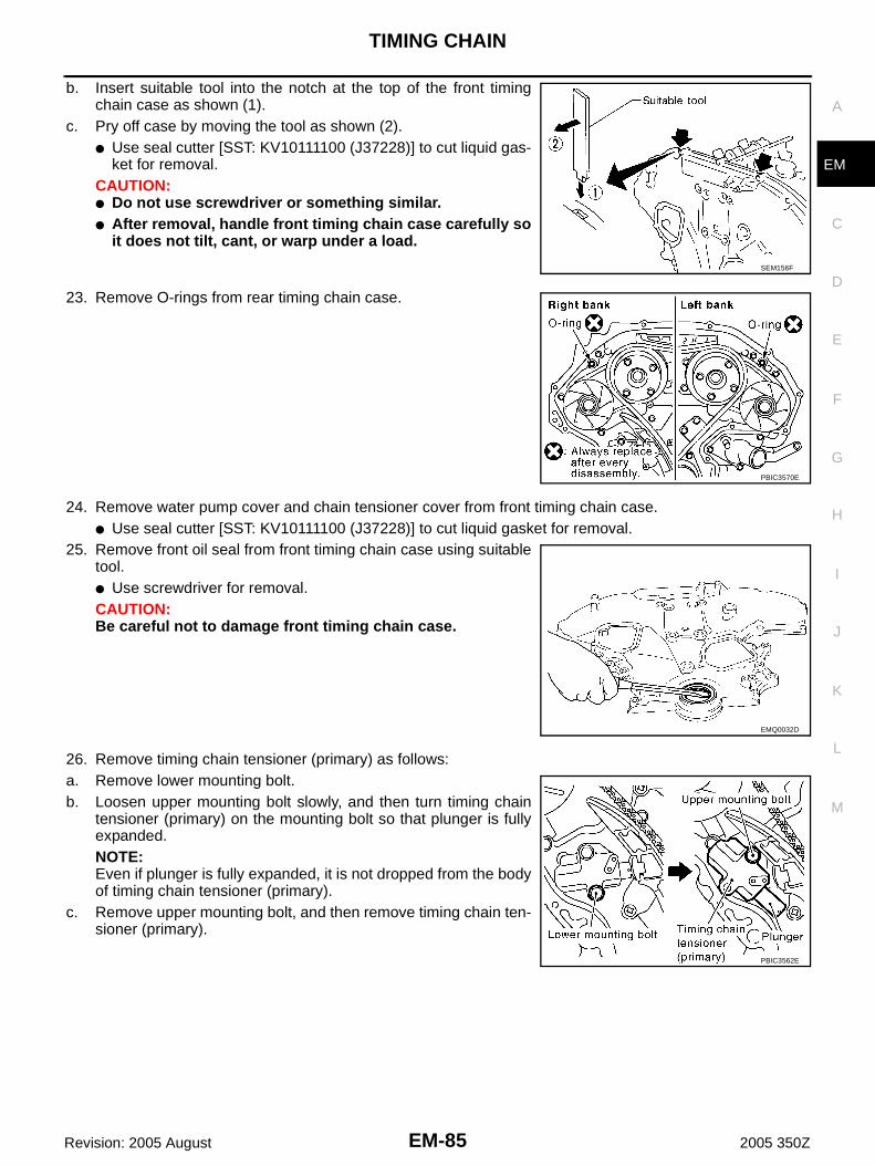
TIMING CHAIN
EM-85
C
D
E
F
G
H
I
J
K
L
M
A
EM
Revision: 2005 August 2005 350Z
b. Insert suitable tool into the notch at the top of the front timingchain case as shown (1).
c. Pry off case by moving the tool as shown (2).● Use seal cutter [SST: KV10111100 (J37228)] to cut liquid gas-
ket for removal. CAUTION:● Do not use screwdriver or something similar.● After removal, handle front timing chain case carefully so
it does not tilt, cant, or warp under a load.
23. Remove O-rings from rear timing chain case.
24. Remove water pump cover and chain tensioner cover from front timing chain case. ● Use seal cutter [SST: KV10111100 (J37228)] to cut liquid gasket for removal.
25. Remove front oil seal from front timing chain case using suitabletool.● Use screwdriver for removal.CAUTION:Be careful not to damage front timing chain case.
26. Remove timing chain tensioner (primary) as follows:a. Remove lower mounting bolt.b. Loosen upper mounting bolt slowly, and then turn timing chain
tensioner (primary) on the mounting bolt so that plunger is fullyexpanded.NOTE:Even if plunger is fully expanded, it is not dropped from the bodyof timing chain tensioner (primary).
c. Remove upper mounting bolt, and then remove timing chain ten-sioner (primary).
SEM156F
PBIC3570E
EMQ0032D
PBIC3562E

EM-86
TIMING CHAIN
Revision: 2005 August 2005 350Z
27. Remove internal chain guide, tension guide and slack guide.NOTE:Tension guide can be removed after removing timing chain (pri-mary).
28. Remove timing chain (primary) and crankshaft sprocket.CAUTION:After removing timing chain (primary), do not turn crankshaft and camshaft separately, or valveswill strike the piston heads.
29. Remove timing chain (secondary) and camshaft sprockets as follows:a. Attach suitable stopper pin to the right and left timing chain ten-
sioners (secondary).NOTE:● Use approximately 0.5 mm (0.02 in) dia. hard metal pin as a
stopper pin.● For removal of timing chain tensioner (secondary), refer to
EM-102, "CAMSHAFT" . [Removing camshaft bracket (No. 1)is required.]
b. Remove intake and exhaust camshaft sprocket bolts.● Secure the hexagonal portion of camshaft using wrench to
loosen mounting bolts.CAUTION:Do not loosen mounting bolts with securing anythingother than the camshaft hexagonal portion or with ten-sioning the timing chain.
c. Remove timing chain (secondary) together with camshaft sprockets.CAUTION:● Handle carefully to avoid any shock to camshaft sprocket.
PBIC3563E
PBIC3564E
KBIA4379J

TIMING CHAIN
EM-87
C
D
E
F
G
H
I
J
K
L
M
A
EM
Revision: 2005 August 2005 350Z
● Do not disassemble. (Do not loosen bolts “A” and “B” asshown in the figure).
NOTE:Camshaft sprocket (INT) is two-for-one structure of primary andsecondary sprockets.
30. Remove water pump. Refer to CO-23, "WATER PUMP" .31. Remove rear timing chain case as follows:a. Loosen and remove mounting bolts in reverse order as shown in
the figure.b. Cut liquid gasket using seal cutter [SST: KV10111100 (J37228)]
and remove rear timing chain case.
CAUTION:● Do not remove plate metal cover of oil passage.● After removal, handle rear timing chain case carefully so
it does not tilt, cant, or warp under a load.
32. Remove O-rings from cylinder head.
PBIC3565E
SEM735G
KBIA1307E
SBIA0496E

EM-88
TIMING CHAIN
Revision: 2005 August 2005 350Z
33. Remove O-rings from cylinder block.
34. Remove timing chain tensioners (secondary) from cylinder head as follows, if necessary.a. Remove camshaft brackets (No. 1). Refer to EM-103, "REMOVAL" .b. Remove timing chain tensioners (secondary) with stopper pin attached.35. Use scraper to remove all traces of old liquid gasket from front
and rear timing chain cases, and opposite mating surfaces.
● Remove old liquid gasket from bolt hole and thread.
36. Use scraper to remove all traces of liquid gasket from waterpump cover, chain tensioner cover and intake valve timing con-trol covers.
PBIC0788E
PBIC3492E
PBIC2084E
SEM926E

TIMING CHAIN
EM-89
C
D
E
F
G
H
I
J
K
L
M
A
EM
Revision: 2005 August 2005 350Z
INSPECTION AFTER REMOVALTiming ChainCheck for cracks and any excessive wear at link plates and rollerlinks of timing chain. Replace timing chain as necessary.
PBIC0282E

EM-90
TIMING CHAIN
Revision: 2005 August 2005 350Z
INSTALLATIONNOTE:● The below figure shows the relationship between the mating mark on each timing chain and that on the
corresponding sprocket, with the components installed.● In this figure, the drum of exhaust side camshaft sprocket has been omitted.
1. Install timing chain tensioners (secondary) to cylinder head as follows if removed. Refer to EM-107,"INSTALLATION" .
a. Install timing chain tensioners (secondary) with stopper pin attached and new O-ring.b. Install camshaft brackets (No. 1). Refer to EM-107, "INSTALLATION" .2. Install rear timing chain case as follows:a. Install new O-rings onto cylinder block.
PBIC3590E
PBIC0788E

TIMING CHAIN
EM-91
C
D
E
F
G
H
I
J
K
L
M
A
EM
Revision: 2005 August 2005 350Z
b. Install new O-rings to cylinder head.
c. Apply liquid gasket with tube presser [SST: WS39930000 ( — )] to rear timing chain case back side asshown in the figure.Use Genuine RTV Silicone Sealant or equivalent. Refer to GI-47, "RECOMMENDED CHEMICALPRODUCTS AND SEALANTS" .CAUTION:● For “A” in the figure, completely wipe out liquid gasket extended on a portion touching at
engine coolant.
SBIA0496E

EM-92
TIMING CHAIN
Revision: 2005 August 2005 350Z
● Apply liquid gasket on installation position of water pump and cylinder head very completely.
d. Align rear timing chain case and water pump assembly with dowel pins (right and left) on cylinder blockand install rear timing chain case.● Make sure O-rings stay in place during installation to cylinder block and cylinder head.
e. Tighten mounting bolts in numerical order as shown in the fig-ure.● There are two type mounting bolts. Refer to the following for
locating bolts.
Bolt length: Bolt position20 mm (0.79 in) : 1, 2, 3, 6, 7, 8, 9, 1016 mm (0.63 in) : Except the above
: 11.7 - 13.7 N·m (1.2 - 1.4 kg-m, 9 - 10 ft-lb)
PBIC2659E
SEM735G

TIMING CHAIN
EM-93
C
D
E
F
G
H
I
J
K
L
M
A
EM
Revision: 2005 August 2005 350Z
f. After all bolts are tightened, retighten them to the specified in numerical order shown in the figure.● If liquid gasket protrudes, wipe it off immediately.
g. After installing rear timing chain case, check the surface heightdifference between following parts on oil pan (upper) mountingsurface.
● If not within standard, repeat the installation procedure.
3. Install water pump with new O-rings. Refer to CO-23, "WATER PUMP" .4. Make sure that dowel pin holes (small dia. side) and crankshaft
key are located as shown in the figure. (No. 1 cylinder at com-pression TDC)● NOTE:
Though camshaft does not stop at the position as shown inthe figure, for the placement of cam nose, it is generallyaccepted camshaft is placed for the same direction of the fig-ure.
CAUTION:The small dia. side of camshaft dowel pin holes should be used. (The large dia. side is not used.)
5. Install timing chains (secondary) and camshaft sprockets as follows:CAUTION:● When replacing camshaft sprocket (EXH), replace valve timing control cover (including magnet
retarder and cover).● Mating marks between timing chain and sprockets slip easily. Confirm all mating mark positions
repeatedly during the installation process.a. Push plunger of timing chain tensioner (secondary) and keep it
pressed in with stopper pin.
StandardRear timing chain case to cylinder block:
–0.24 to 0.14 mm (–0.0094 to 0.0055 in)
SEM943G
Camshaft dowel pin hole (intake side): At cylinder head upper face side in each bank.
Camshaft dowel pin hole (exhaust side): At cylinder head lower face side in each bank.
Crankshaft key: At cylinder head side of right bank.
PBIC3498E
SEM430G

EM-94
TIMING CHAIN
Revision: 2005 August 2005 350Z
b. Install timing chains (secondary) and camshaft sprockets.● Align the mating marks on timing chain (secondary) (gold link)
with the ones on intake and exhaust camshaft sprockets(punched), and install them.NOTE:● Mating marks for intake camshaft sprocket are on the back
side of camshaft sprocket (secondary).● There are two types of mating marks, circle and oval types.
They should be used for the right and left banks, respec-tively.
● Align dowel pin hole on the small diameter side of the cam-shaft front end with dowel pin on the back side of camshaftsprockets, and install them.
● In case that positions of each mating mark and each dowelpin are not fit on mating parts, make fine adjustment to theposition holding the hexagonal portion on camshaft withwrench or equivalent.
● Mounting bolts for camshaft sprockets must be tightened inthe step “d”. Tightening them by hand is enough to preventthe dislocation of dowel pins.
c. Make sure that timing chain (secondary) is not loose from each camshaft sprocket.● Make sure the mating marks (punched) on each camshaft
sprocket are positioned on the mating marks (gold link) ontiming chain (secondary).NOTE:Mating mark (punched) in the figure is for checking loose atthis step.
d. Tighten camshaft sprocket mounting bolts.● Secure camshaft using wrench at the hexagonal portion to
tighten mounting bolts.
Right bank : Use circle type.Left bank : Use oval type.
PBIC3566E
PBIC3567E
KBIA4379J

TIMING CHAIN
EM-95
C
D
E
F
G
H
I
J
K
L
M
A
EM
Revision: 2005 August 2005 350Z
e. Pull stopper pins out from timing chain tensioners (secondary).
6. Install tension guide.7. Install timing chain (primary) as follows:a. Install crankshaft sprocket.
● Make sure the mating marks on crankshaft sprocket face thefront of engine.
b. Install timing chain (primary).● Install timing chain (primary) so the mating mark (punched) on
camshaft sprocket is aligned with the pink link on timingchain, while the mating mark (notched) on crankshaftsprocket is aligned with the orange one on timing chain, asshown in the figure.
● When it is difficult to align mating marks of timing chain (pri-mary) with each sprocket, gradually turn camshaft usingwrench on the hexagonal portion to align it with the matingmarks.
● During alignment, be careful to prevent dislocation of matingmark alignments of timing chains (secondary).
PBIC3564E
SEM929E
PBIC3494E

EM-96
TIMING CHAIN
Revision: 2005 August 2005 350Z
8. Install internal chain guide, slack guide and timing chain ten-sioner (primary).
CAUTION:Do not overtighten slack guide mounting bolts. It is normalfor a gap to exist under the bolt seats when mounting boltsare tightened to specification.
9. Install the timing chain tensioner (primary) with the following procedure:a. Pull plunger stopper tab up (or turn lever downward) so as to
remove plunger stopper tab from the ratchet of plunger.NOTE:Plunger stopper tab and lever are synchronized.
b. Push plunger into the inside of tensioner body.c. Hold plunger in the fully compressed position by engaging
plunger stopper tab with the tip of ratchet.d. To secure lever, insert stopper pin through hole of lever into ten-
sioner body hole.● The lever parts and the tab are synchronized. Therefore, the
plunger will be secured under this condition.NOTE:Figure shows the example of 1.2 mm (0.047 in) diameter thin screwdriver being used as the stopper pin.
PBIC3563E
PBIC2633E
PBIC3568E

TIMING CHAIN
EM-97
C
D
E
F
G
H
I
J
K
L
M
A
EM
Revision: 2005 August 2005 350Z
e. Install timing chain tensioner (primary).● Remove any dirt and foreign materials completely from the
back and the mounting surfaces of timing chain tensioner (pri-mary).
f. Pull out stopper pin after installing, and then release plunger.
10. Make sure again that the mating marks on sprockets and timing chain have not slipped out of alignment.11. Install new O-rings on rear timing chain case.
12. Install new front oil seal on front timing chain case.● Apply new engine oil to both oil seal lip and dust seal lip.● Install it so that each seal lip is oriented as shown in the fig-
ure.
● Using suitable drift, press-fit oil seal until it becomes flush withfront timing chain case end face.
● Make sure the garter spring is in position and seal lip is notinverted.
13. Install water pump cover and chain tensioner cover to front timing chain case.
PBIC3569E
PBIC3570E
SEM715A
PBIC0790E

EM-98
TIMING CHAIN
Revision: 2005 August 2005 350Z
● Apply a continuous bead of liquid gasket with tube presser[SST: WS39930000 ( — )] to front timing chain case asshown in the figure.Use Genuine RTV Silicone Sealant or equivalent. Refer toGI-47, "RECOMMENDED CHEMICAL PRODUCTS ANDSEALANTS" .
14. Install front timing chain case as follows:a. Apply a continuous bead of liquid gasket with tube presser [SST:
WS39930000 ( — )] to front timing chain case back side asshown in the figure.Use Genuine RTV Silicone Sealant or equivalent. Refer toGI-47, "RECOMMENDED CHEMICAL PRODUCTS ANDSEALANTS" .
b. Install front timing chain case as to fit its dowel pin hole together dowel pin on rear timing chain case.c. Tighten mounting bolts to the specified torque in numerical order
as shown in the figure.● There are two type of mounting bolts. Refer to the following
for locating bolts.
d. After all bolts are tightened, retighten them to the specifiedtorque in numerical order shown in the figure.CAUTION:Be sure to wipe off any excessive liquid gasket leaking on surface mating with oil pan (upper).
SEM744GA
PBIC3495E
M8 bolts : 1, 2
: 25.5 - 31.3 N·m (2.6 - 3.2 kg-m, 19 - 23 ft-lb)M6 bolts : Except the above
: 11.7 - 13.7 N·m (1.2 - 1.4 kg-m, 9 - 10 ft-lb)KBIA4375J

TIMING CHAIN
EM-99
C
D
E
F
G
H
I
J
K
L
M
A
EM
Revision: 2005 August 2005 350Z
e. After installing front timing chain case, check the surface heightdifference between the following parts on the oil pan (upper)mounting surface.
● If not within standard, repeat the installation procedure.
15. Install right and left valve timing control covers as follows:a. Install new seal rings in shaft grooves.
b. Install magnet retarder aligning the dowel pins of the back withthe cover side dowel pin holes securely. Simultaneously insertthe harness into the installation groove securely.NOTE:Figure shows the structure of the parts. Therefore, magnetretarder is being removed from the cover in this figure. But, ifmagnet retarder is in the correct position, omit step “b” and per-form step “c”.
c. To check the joint between dowel pins and dowel pin holes,check the looseness in the axle direction by pushing the matingsurface of magnet retarder at several places and the circumfer-ential looseness (between dowel pins and dowel pin holes) bytwisting in the circumferential direction.CAUTION:Always perform this procedure when removing because thegap between dowel pins and dowel pin holes may not becaused on purpose.
StandardFront timing chain case to rear timing chain case:
–0.14 to 0.14 mm (–0.005 to 0.0055 in)
SEM943G
PBIC3571E
PBIC3572E
PBIC3573E

EM-100
TIMING CHAIN
Revision: 2005 August 2005 350Z
d. Install valve timing control cover to front timing chain case.CAUTION:● Do not face the magnet retarder side down to prevent
magnet retarder from dropping.● Check the mating surface of magnet retarder and the
drum of exhaust side camshaft sprocket for foreign mate-rials.
● Align the center of both shaft holes of the shaft and theintake side camshaft sprocket, and then insert them.
● Be careful not to drop the seal ring from the shaft groove.● When setting the valve timing control cover in position
by hand, if valve timing control cover is not contacting with the front timing chain case, thedowel pin of magnet retarder may not be aligned with the dowel pin holes of cover. In this case,return to step “b”.
e. Tighten mounting bolts in numerical order as shown in the fig-ure.CAUTION:Completely tighten the mounting bolts with the seat surfaceof valve timing control cover contacting with front timingchain case.
16. Install oil pans (upper and lower). Refer to EM-29, "OIL PAN AND OIL STRAINER" .17. Install rocker covers (right and left banks). Refer to EM-44, "ROCKER COVER" .18. Install crankshaft pulley as follows:a. Fix crankshaft using ring gear stopper [SST: KV10117700 (J44716)].b. Install crankshaft pulley, taking care not to damage front oil seal.
● When press-fitting crankshaft pulley with plastic hammer, tap on its center portion (not circumference).c. Tighten crankshaft pulley bolt.
d. Turn crankshaft pulley bolt 84 to 90 degrees clockwise [Target:90 degrees (angle tightening)].CAUTION:Check the tightening angle by using the angle wrench[SST]. Avoid judgement by visual inspection without SST.● Check tightening angle indicated on the angle wrench indica-
tor plate.
19. Rotate crankshaft pulley in normal direction (clockwise when viewed from engine front) to confirm it turnssmoothly.
20. Install in the reverse order of removal after this step.
PBIC3561E
PBIC3560E
: 39.2 - 49.0 N·m (4.0 - 5.0 kg-m, 29 - 36 ft-lb)
PBIC3821E

TIMING CHAIN
EM-101
C
D
E
F
G
H
I
J
K
L
M
A
EM
Revision: 2005 August 2005 350Z
INSPECTION AFTER INSTALLATIONInspection for LeaksThe following are procedures for checking fluids leak, lubricates leak and exhaust gases leak.● Before starting engine, check oil/fluid levels including engine coolant and engine oil. If less than required
quantity, fill to the specified level. Refer to MA-12, "RECOMMENDED FLUIDS AND LUBRICANTS" .● Use procedure below to check for fuel leakage.– Turn ignition switch “ON” (with engine stopped). With fuel pressure applied to fuel piping, check for fuel
leakage at connection points.– Start engine. With engine speed increased, check again for fuel leakage at connection points.● Run engine to check for unusual noise and vibration.
NOTE:If hydraulic pressure inside timing chain tensioner drops after removal/installation, slack in the guide maygenerate a pounding noise during and just after engine start. However, this is normal. Noise will stop afterhydraulic pressure rises.
● Warm up engine thoroughly to make sure there is no leakage of fuel, exhaust gases, or any oil/fluidsincluding engine oil and engine coolant.
● Bleed air from lines and hoses of applicable lines, such as in cooling system.● After cooling down engine, again check oil/fluid levels including engine oil and engine coolant. Refill to the
specified level, if necessary.
Summary of the inspection items:
* Transmission/transaxle/CVT fluid, power steering fluid, brake fluid, etc.
Item Before starting engine Engine running After engine stopped
Engine coolant Level Leakage Level
Engine oil Level Leakage Level
Other oils and fluid* Level Leakage Level
Fuel Leakage Leakage Leakage
Exhaust gases — Leakage —
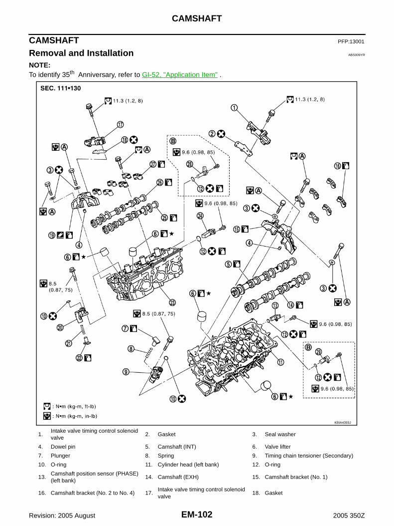
EM-102
CAMSHAFT
Revision: 2005 August 2005 350Z
CAMSHAFT PFP:13001
Removal and Installation ABS009YR
NOTE:To identify 35th Anniversary, refer to GI-52, "Application Item" .
1.Intake valve timing control solenoid valve
2. Gasket 3. Seal washer
4. Dowel pin 5. Camshaft (INT) 6. Valve lifter
7. Plunger 8. Spring 9. Timing chain tensioner (Secondary)
10. O-ring 11. Cylinder head (left bank) 12. O-ring
13.Camshaft position sensor (PHASE) (left bank)
14. Camshaft (EXH) 15. Camshaft bracket (No. 1)
16. Camshaft bracket (No. 2 to No. 4) 17.Intake valve timing control solenoid valve
18. Gasket
KBIA4393J

CAMSHAFT
EM-103
C
D
E
F
G
H
I
J
K
L
M
A
EM
Revision: 2005 August 2005 350Z
● Refer to GI-10, "Components" for symbol mark in the figure.
REMOVAL1. Remove front timing chain case, camshaft sprocket, timing chain and rear timing chain case. Refer to EM-
59, "TIMING CHAIN" .2. Remove camshaft position sensor (PHASE) (right and left
banks) and exhaust valve timing control position sensor (rightand left banks) (only for 35th Anniversary) from cylinder headback side.CAUTION:● Handle carefully to avoid dropping and shocks.● Do not disassemble.● Do not allow metal powder to adhere to magnetic part at
sensor tip.● Do not place sensors in a location where they are
exposed to magnetism.
3. Remove intake valve timing control solenoid valves.● Discard intake valve timing control solenoid valve gaskets and
use new gaskets for installation.
4. Remove intake and exhaust camshaft brackets.● Mark camshafts, camshaft brackets and bolts so they are placed in the same position and direction for
installation.
19. Camshaft bracket (No. 1) 20. Timing chain tensioner (Secondary) 21. Spring
22. Plunger 23. Cylinder head (left bank) 24.Camshaft position sensor (PHASE) (right bank)
25. Camshaft (INT) 26. Camshaft (EXH) 27. Camshaft bracket (No. 2 to No. 4)
28.Exhaust valve timing control position sensor (right bank)
29.Exhaust valve timing control position sensor (left bank)
A. Refer to EM-107 . B. Only for 35th Anniversary
KBIA1046E
SEM443GA

EM-104
CAMSHAFT
Revision: 2005 August 2005 350Z
● Equally loosen camshaft bracket bolts in several steps inreverse order as shown in the figure.
5. Remove camshaft.6. Remove valve lifter.
● Identify installation positions, and store them without mixing them up.7. Remove timing chain tensioner (secondary) from cylinder head.
● Remove timing chain tensioner (secondary) with its stopperpin attached.
NOTE:Stopper pin was attached when timing chain (secondary) wasremoved.
INSPECTION AFTER REMOVALCamshaft Runout1. Put V-block on precise flat table, and support No. 2 and 4 jour-
nals of camshaft.CAUTION:Do not support journal No. 1 (on the side of camshaftsprocket) because it has a different diameter from the otherthree locations.
2. Set dial indicator vertically to No. 3 journal.3. Turn camshaft to one direction with hands, and measure the
camshaft runout on a dial indicator. (Total indicator reading)
4. If it exceeds the limit, replace camshaft.
PBIC2050E
PBIC2111E
Standard : Less than 0.02 mm (0.0008 in)Limit : 0.05 mm (0.0020 in)
PBIC0929E

CAMSHAFT
EM-105
C
D
E
F
G
H
I
J
K
L
M
A
EM
Revision: 2005 August 2005 350Z
Camshaft Cam Height1. Measure the camshaft cam height with a micrometer.
2. If wear is beyond the limit, replace camshaft.
Camshaft Journal Oil ClearanceCAMSHAFT JOURNAL DIAMETER● Measure the outer diameter of camshaft journal with a microme-
ter.
CAMSHAFT BRACKET INNER DIAMETER ● Tighten camshaft bracket bolt with the specified torque. Refer to EM-107, "INSTALLATION" for the tight-
ening procedure.● Measure the inner diameter “A” of camshaft bracket with a bore
gauge.
CAMSHAFT JOURNAL OIL CLEARANCE● (Oil clearance) = (Camshaft bracket inner diameter) – (Camshaft journal diameter)
Standard cam height:Intake
Except for 35th Anniversary: 44.865 - 45.055 mm (1.7663 - 1.7738 in)
For 35th Anniversary: 45.865 - 46.055 mm (1.8057 - 1.8132 in)
Exhaust
Except for 35th Anniversary: 44.865 - 45.055 mm (1.7663 - 1.7738 in)
For 35th Anniversary: 45.875 - 46.055 mm (1.8061 - 1.8136 in)
Cam wear limit: 0.2 mm (0.008 in)
EMQ0072D
Standard:No. 1 : 25.935 - 25.955 mm (1.0211 - 1.0218 in)No. 2, 3, 4 : 23.445 - 23.465 mm (0.9230 - 0.9238 in)
PBIC0040E
Standard:No. 1 : 26.000 - 26.021 mm (1.0236 - 1.0244 in)No. 2, 3, 4 : 23.500 - 23.521 mm (0.9252 - 0.9260 in)
PBIC1645E
Standard:No. 1 : 0.045 - 0.086 mm (0.0018 - 0.0034 in)No. 2, 3, 4 : 0.035 - 0.076 mm (0.0014 - 0.0030 in)
Limit : 0.15 mm (0.0059 in)

EM-106
CAMSHAFT
Revision: 2005 August 2005 350Z
● If it exceeds the limit, replace either or both camshaft and cylinder head.NOTE:Camshaft brackets cannot be replaced as single parts, because there are machined together with cylinderhead. Replace whole cylinder head assembly.
Camshaft End Play● Install a dial indicator in thrust direction on front end of camshaft.
Measure the end play of a dial indicator when camshaft ismoved forward/backward (in direction to axis).
● Measure the following parts if out of the limit.– Dimension “A” for camshaft No. 1 journal
– Dimension “B” for cylinder head No. 1 journal bearing
● Refer to the standards above, and then replace camshaft and/orcylinder head.
Camshaft Sprocket Runout1. Put V-block on precise flat table, and support No. 2 and 4 journal of camshaft.
CAUTION:Do not support journal No. 1 (on the side of camshaft sprocket) because it has a different diameterfrom the other three locations.
2. Measure the camshaft sprocket runout with a dial indicator.(Total indicator reading)
● If it exceeds the limit, replace camshaft sprocket.CAUTION:When replacing camshaft sprocket (EXH), replace valvetiming control cover (including magnet retarder and cover).(Only for 35th Anniversary)
Valve Lifter Check if surface of valve lifter has any wear or cracks.● If anything above is found, replace valve lifter. Refer to EM-172,
"Available Valve Lifter" .
Standard : 0.115 - 0.188 mm (0.0045 - 0.0074 in)Limit : 0.24 mm (0.0094 in)
SEM864E
Standard : 27.500 - 27.548 mm (1.0827 - 1.0846 in)
Standard : 27.360 - 27.385 mm (1.0772 - 1.0781 in)
KBIA2404J
Limit : 0.15 mm (0.0059 in)
PBIC0930E
KBIA0182E

CAMSHAFT
EM-107
C
D
E
F
G
H
I
J
K
L
M
A
EM
Revision: 2005 August 2005 350Z
Valve Lifter ClearanceVALVE LIFTER OUTER DIAMETER● Measure the outer diameter at 1/2 height of valve lifter with a
micrometer since valve lifter is in barrel shape.
VALVE LIFTER HOLE DIAMETER● Measure the inner diameter of valve lifter hole of cylinder head
with an inside micrometer.
VALVE LIFTER CLEARANCE● (Valve lifter clearance) = (Valve lifter hole diameter) – (Valve lifter outer diameter)
● If the calculated value is out of the standard, referring to each standard of valve lifter outer diameter andvalve lifter hole diameter, replace either or both valve lifter and cylinder head.
INSTALLATION1. Install timing chain tensioners (secondary) on both sides of cyl-
inder head.● Install timing chain tensioner with its stopper pin attached. ● Install timing chain tensioner with sliding part facing down-
ward on right-side cylinder head, and with sliding part facingupward on left-side cylinder head.
● Install new O-ring as shown in the figure.
2. Install valve lifter.● Install it in the original position.
3. Install camshafts. (Except for 35th Anniversary)
Standard (Intake and exhaust): 33.977 - 33.987 mm (1.3377 - 1.3381 in)
JEM798G
Standard (Intake and exhaust): 34.000 - 34.016 mm (1.3386 - 1.3392 in)
SEM867E
Standard (Intake and exhaust): 0.013 - 0.039 mm (0.0005 - 0.0015 in)
PBIC2111E

EM-108
CAMSHAFT
Revision: 2005 August 2005 350Z
● Install camshaft with dowel pin attached to its front end faceon the exhaust side.
● Follow your identification marks made during removal, or fol-low the identification marks that are present on new cam-shafts for proper placement and direction.
● Install camshaft so that dowel pin hole and dowel pin on frontend face are positioned as shown in the figure. (No. 1 cylinderTDC on its compression stroke)NOTE:● Large and small pin holes are located on front end face of
camshaft (INT), at intervals of 180 degrees. Face small dia.side pin hole upward (in cylinder head upper face direc-tion).
● Though camshaft does not stop at the portion as shown inthe figure, for the placement of cam nose, it is generallyaccepted camshaft is placed for the same direction of thefigure.
4. Install camshafts. (For 35th Anniversary)● The distinguishing between intake and exhaust depends on
the difference of the shape (the number of the notch) of thesignal plate area on rear end of camshaft.
KBIA1071E
Bank INT/EXH Dowel pinPaint marks Identification
markM1 M2
RHINT No Pink No RE
EXH Yes No Orange RE
LHINT No Pink No LH
EXH Yes No Orange LH KBIA1009E
PBIC2478E
Intake : 6 notchesExhaust : 3 notches
PBIC3574E

CAMSHAFT
EM-109
C
D
E
F
G
H
I
J
K
L
M
A
EM
Revision: 2005 August 2005 350Z
● Follow your identification marks made during removal, or fol-low the identification marks that are present on new cam-shafts for proper placement and direction.
● Install camshaft so that dowel pin hole (small dia. side) frontend face are positioned as shown in the figure. (No. 1 cylinderTDC on its compression stroke)
NOTE:● Large and small dowel pin holes are located on the front
end of camshaft at 180 degree intervals. Only the smalldowel pin hole position is described in this text because thelarge dowel pin hole is not used for assembly of engine.
● Though camshaft does not stop at the portion as shown inthe figure, for the placement of cam nose, it is generally accepted camshaft is placed for the samedirection of the figure.
5. Install camshaft brackets.● Remove foreign material completely from camshaft bracket
backside and from cylinder head installation face.● Install camshaft bracket in original position and direction as
shown in the figure.
Bank INT/EXHPaint marks Identification
markM1 M2
RHINT Brown No RE
EXH No Brown RE
LHINT Brown No LH
EXH No Brown LH PBIC3499E
Intake : On cylinder head upper surfaceExhaust : On cylinder head lower surface
PBIC3500E
PBIC2051E
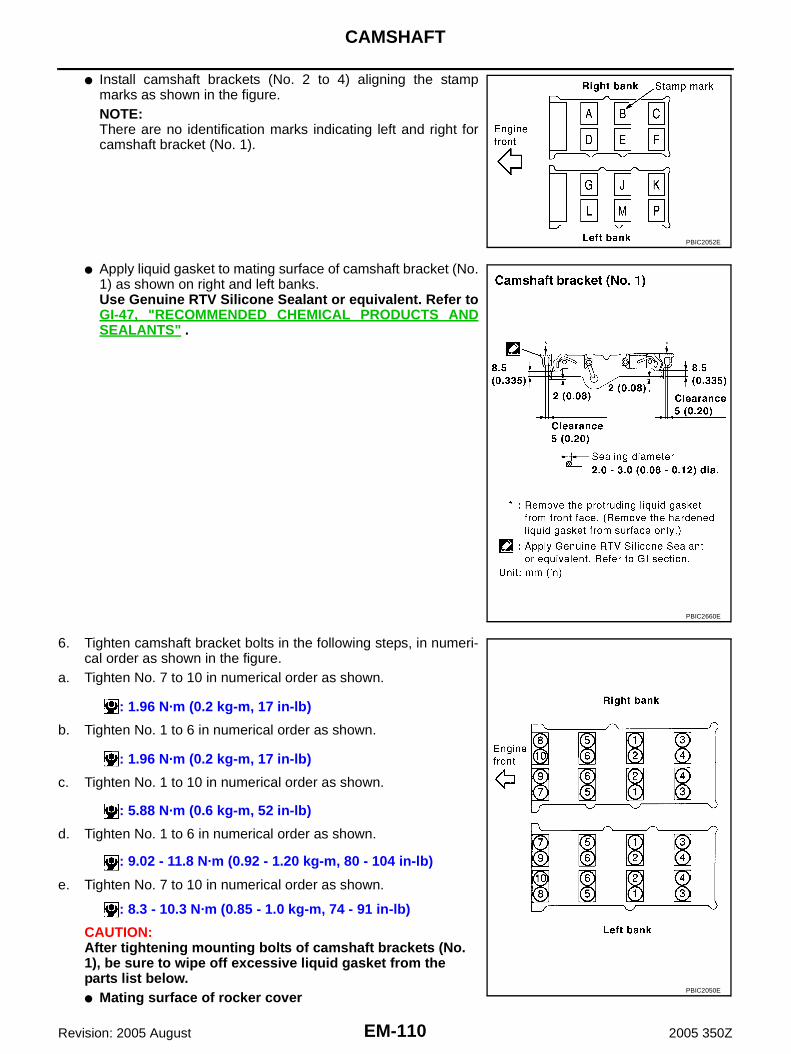
EM-110
CAMSHAFT
Revision: 2005 August 2005 350Z
● Install camshaft brackets (No. 2 to 4) aligning the stampmarks as shown in the figure.NOTE:There are no identification marks indicating left and right forcamshaft bracket (No. 1).
● Apply liquid gasket to mating surface of camshaft bracket (No.1) as shown on right and left banks.Use Genuine RTV Silicone Sealant or equivalent. Refer toGI-47, "RECOMMENDED CHEMICAL PRODUCTS ANDSEALANTS" .
6. Tighten camshaft bracket bolts in the following steps, in numeri-cal order as shown in the figure.
a. Tighten No. 7 to 10 in numerical order as shown.
b. Tighten No. 1 to 6 in numerical order as shown.
c. Tighten No. 1 to 10 in numerical order as shown.
d. Tighten No. 1 to 6 in numerical order as shown.
e. Tighten No. 7 to 10 in numerical order as shown.
CAUTION:After tightening mounting bolts of camshaft brackets (No. 1), be sure to wipe off excessive liquid gasket from the parts list below.● Mating surface of rocker cover
PBIC2052E
PBIC2660E
: 1.96 N·m (0.2 kg-m, 17 in-lb)
: 1.96 N·m (0.2 kg-m, 17 in-lb)
: 5.88 N·m (0.6 kg-m, 52 in-lb)
: 9.02 - 11.8 N·m (0.92 - 1.20 kg-m, 80 - 104 in-lb)
: 8.3 - 10.3 N·m (0.85 - 1.0 kg-m, 74 - 91 in-lb)
PBIC2050E

CAMSHAFT
EM-111
C
D
E
F
G
H
I
J
K
L
M
A
EM
Revision: 2005 August 2005 350Z
● Mating surface of rear timing chain case7. Measure difference in levels between front end faces of cam-
shaft bracket (No. 1) and cylinder head.
● Measure two positions (both intake and exhaust side) for asingle bank.
● If the measured value is out of the standard, re-install cam-shaft bracket (No. 1).
8. Inspect and adjust the valve clearance. Refer to EM-113, "Valve Clearance" .9. Install camshaft position sensor (PHASE) (right and left banks) and exhaust valve timing control position
sensor (right and left banks) (only for 35th Anniversary) to the cylinder head back side.● Install them in the position shown in the figure.
10. Install in the reverse order of removal after this step.
Standard : –0.14 to 0.14 mm (–0.0055 to 0.0055 in)
EMQ0044D
PBIC3518E
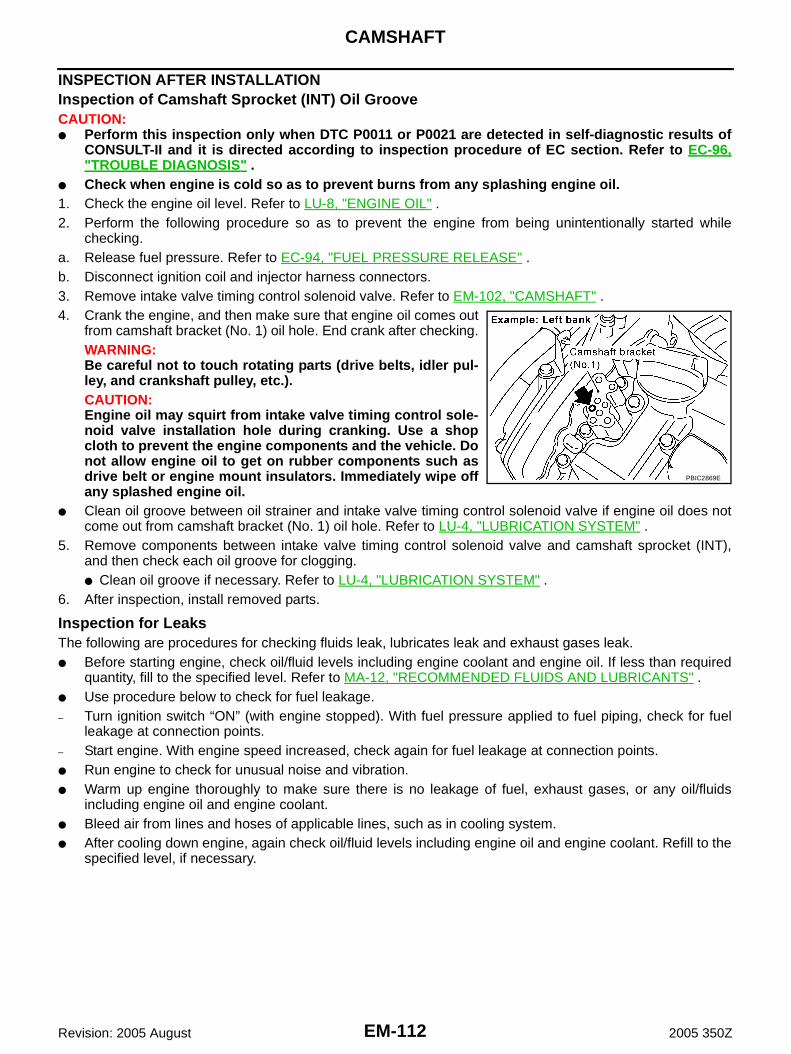
EM-112
CAMSHAFT
Revision: 2005 August 2005 350Z
INSPECTION AFTER INSTALLATIONInspection of Camshaft Sprocket (INT) Oil GrooveCAUTION:● Perform this inspection only when DTC P0011 or P0021 are detected in self-diagnostic results of
CONSULT-II and it is directed according to inspection procedure of EC section. Refer to EC-96,"TROUBLE DIAGNOSIS" .
● Check when engine is cold so as to prevent burns from any splashing engine oil.1. Check the engine oil level. Refer to LU-8, "ENGINE OIL" .2. Perform the following procedure so as to prevent the engine from being unintentionally started while
checking.a. Release fuel pressure. Refer to EC-94, "FUEL PRESSURE RELEASE" .b. Disconnect ignition coil and injector harness connectors.3. Remove intake valve timing control solenoid valve. Refer to EM-102, "CAMSHAFT" .4. Crank the engine, and then make sure that engine oil comes out
from camshaft bracket (No. 1) oil hole. End crank after checking.WARNING:Be careful not to touch rotating parts (drive belts, idler pul-ley, and crankshaft pulley, etc.).CAUTION:Engine oil may squirt from intake valve timing control sole-noid valve installation hole during cranking. Use a shopcloth to prevent the engine components and the vehicle. Donot allow engine oil to get on rubber components such asdrive belt or engine mount insulators. Immediately wipe offany splashed engine oil.
● Clean oil groove between oil strainer and intake valve timing control solenoid valve if engine oil does notcome out from camshaft bracket (No. 1) oil hole. Refer to LU-4, "LUBRICATION SYSTEM" .
5. Remove components between intake valve timing control solenoid valve and camshaft sprocket (INT),and then check each oil groove for clogging.● Clean oil groove if necessary. Refer to LU-4, "LUBRICATION SYSTEM" .
6. After inspection, install removed parts.
Inspection for LeaksThe following are procedures for checking fluids leak, lubricates leak and exhaust gases leak.● Before starting engine, check oil/fluid levels including engine coolant and engine oil. If less than required
quantity, fill to the specified level. Refer to MA-12, "RECOMMENDED FLUIDS AND LUBRICANTS" .● Use procedure below to check for fuel leakage.– Turn ignition switch “ON” (with engine stopped). With fuel pressure applied to fuel piping, check for fuel
leakage at connection points.– Start engine. With engine speed increased, check again for fuel leakage at connection points.● Run engine to check for unusual noise and vibration.● Warm up engine thoroughly to make sure there is no leakage of fuel, exhaust gases, or any oil/fluids
including engine oil and engine coolant.● Bleed air from lines and hoses of applicable lines, such as in cooling system.● After cooling down engine, again check oil/fluid levels including engine oil and engine coolant. Refill to the
specified level, if necessary.
PBIC2869E

CAMSHAFT
EM-113
C
D
E
F
G
H
I
J
K
L
M
A
EM
Revision: 2005 August 2005 350Z
Summary of the inspection items:
* Transmission/transaxle/CVT fluid, power steering fluid, brake fluid, etc.
Valve Clearance ABS009YS
INSPECTIONPerform inspection as follows after removal, installation or replacement of camshaft or valve-related parts, or ifthere is unusual engine conditions regarding valve clearance.In cases of removing/installing or replacing camshaft and valve-related parts, or of unusual engine conditions due to changes invalve clearance (found malfunctions during stating, idling or causingnoise), perform inspection as follows:
1. Remove rocker covers (right and left bank). Refer to EM-44, "ROCKER COVER" .2. Measure the valve clearance as follows:a. Set No. 1 cylinder at TDC of its compression stroke.
● Rotate crankshaft pulley clockwise to align timing mark(grooved line without color) with timing indicator.
● Make sure that intake and exhaust cam nose on No. 1 cylin-der (engine front side of right bank) are located as shown inthe figure.
● If not, turn crankshaft one revolution (360 degrees) and alignas shown in the figure.
Item Before starting engine Engine running After engine stopped
Engine coolant Level Leakage Level
Engine oil Level Leakage Level
Other oils and fluid* Level Leakage Level
Fuel Leakage Leakage Leakage
Exhaust gases — Leakage —
SEM713A
KBIA1717J
SEM418G

EM-114
CAMSHAFT
Revision: 2005 August 2005 350Z
b. Use a feeler gauge, measure the clearance between valve lifterand camshaft.
Valve clearance:Unit: mm (in)
*: Approximately 80°C (176°F)
● By referring to the figure, measure the valve clearances atlocations marked “×” as shown in the table below (locationsindicated in the figure).
● No. 1 cylinder at compression TDC
c. Rotate crankshaft by 240 degrees clockwise (when viewed fromengine front) to align No. 3 cylinder at TDC of its compressionstroke.NOTE:Crankshaft pulley mounting bolt flange has a stamped line every60 degrees. They can be used as a guide to rotation angle.
SEM139D
Items Cold Hot * (reference data)
Intake 0.26 - 0.34 (0.010 - 0.013) 0.304 - 0.416 (0.012 - 0.016)
Exhaust 0.29 - 0.37 (0.011 - 0.015) 0.308 - 0.432 (0.012 - 0.017)
Measuring position (right bank) No. 1 CYL. No. 3 CYL. No. 5 CYL.
No. 1 cylinder at compression TDC
EXH ×
INT ×
Measuring position (left bank) No. 2 CYL. No. 4 CYL. No. 6 CYL.
No. 1 cylinder at compression TDC
INT ×
EXH ×
PBIC2054E
SEM751G

CAMSHAFT
EM-115
C
D
E
F
G
H
I
J
K
L
M
A
EM
Revision: 2005 August 2005 350Z
● By referring to the figure, measure the valve clearances atlocations marked “×” as shown in the table below (locationsindicated in the figure).
● No. 3 cylinder at compression TDC
d. Rotate crankshaft by 240 degrees clockwise (when viewed fromengine front) to align No. 5 cylinder at TDC of compressionstroke.
● By referring to the figure, measure the valve clearances atlocations marked “×” as shown in the table below (locationsindicated in the figure).
● No. 5 cylinder at compression TDC
Measuring position (right bank) No. 1 CYL. No. 3 CYL. No. 5 CYL.
No. 3 cylinder at compression TDC
EXH ×
INT ×
Measuring position (left bank) No. 2 CYL. No. 4 CYL. No. 6 CYL.
No. 3 cylinder at compression TDC
INT ×
EXH ×
PBIC2055E
SEM751G
Measuring position (right bank) No. 1 CYL. No. 3 CYL. No. 5 CYL.
No. 5 cylinder at compression TDC
EXH ×
INT ×
Measuring position (left bank) No. 2 CYL. No. 4 CYL. No. 6 CYL.
No. 5 cylinder at compression TDC
INT ×
EXH ×
PBIC2056E

EM-116
CAMSHAFT
Revision: 2005 August 2005 350Z
3. If the measured values are out of the standard, perform adjustment. Refer to EM-116, "ADJUSTMENT" .
ADJUSTMENT● Perform adjustment depending on selected head thickness of valve lifter.1. Measure the valve clearance. Refer to EM-113, "INSPECTION" .2. Remove camshaft. Refer to EM-103, "REMOVAL" .3. Remove valve lifters at the locations that are out of the standard.4. Measure the center thickness of removed valve lifters with a
micrometer.
5. Use the equation below to calculate valve lifter thickness for replacement.
● Thickness of new valve lifter can be identified by stamp markson the reverse side (inside the cylinder). Stamp mark 788U or 788R indicates 7.88 mm (0.3102 in) inthickness.NOTE:Two types of stamp marks are used for parallel setting and formanufacturer identification.
Available thickness of valve lifter: 27 sizes with range 7.88 to 8.40 mm (0.3102 to 0.3307 in) in steps of0.02 mm (0.0008 in) (when manufactured at factory). Refer to EM-172, "Available Valve Lifter" .
6. Install selected valve lifter.7. Install camshaft. Refer to EM-107, "INSTALLATION" .8. Manually turn crankshaft pulley a few turns. 9. Make sure that the valve clearances for cold engine are within the specifications by referring to the speci-
fied values. Refer to EM-113, "INSPECTION" .10. Install all removal parts in the reverse order of removal. Refer to EM-107, "INSTALLATION" .11. Warm up the engine, and check for unusual noise and vibration.
KBIA0057E
Valve lifter thickness calculation: t = t1 + (C1 – C2 )t = Valve lifter thickness to be replacedt1 = Removed valve lifter thicknessC1 = Measured valve clearanceC2 = Standard valve clearance:
Intake : 0.30 mm (0.012 in)*Exhaust : 0.33 mm (0.013 in)**: Approximately 20°C (68°F)
KBIA0119E

OIL SEAL
EM-117
C
D
E
F
G
H
I
J
K
L
M
A
EM
Revision: 2005 August 2005 350Z
OIL SEAL PFP:00100
Removal and Installation of Valve Oil Seal ABS009YT
REMOVAL1. Remove camshaft relating to valve oil seal to be removed. Refer to EM-102, "CAMSHAFT" .2. Remove valve lifters. Refer to EM-102, "CAMSHAFT" .3. Turn crankshaft until the cylinder requiring new oil seals is at TDC. This will prevent valve from dropping
into cylinder.4. Remove valve collet.
● Compress valve spring with valve spring compressor, attach-ment, adapter [SST]. Remove valve collet with magnet hand.CAUTION:When working, take care not to damage valve lifter holes.
5. Remove valve spring retainer, valve spring and valve spring seat.6. Remove valve oil seal using valve oil seal puller [SST].
INSTALLATION1. Apply engine oil on new valve oil seal joint and seal lip.2. Using valve oil seal drift [SST], press fit valve seal to height “H”
shown in the figure.NOTE:Dimension “H”: Height measured before valve spring seat instal-lation
3. Install in the reverse order of removal after this step.
PBIC1803E
PBIC0884E
Intake and exhaust : 14.3 - 14.9 mm (0.563 - 0.587 in)
PBIC0802E

EM-118
OIL SEAL
Revision: 2005 August 2005 350Z
Removal and Installation of Front Oil Seal ABS009YU
REMOVAL1. Remove the following parts:
● Undercover● Drive belts; Refer to EM-14, "DRIVE BELTS" .● Radiator cooling fan assembly; Refer to CO-21, "COOLING FAN" .● Starter motor; Refer to SC-10, "STARTING SYSTEM" .● Crankshaft pulley; Refer to EM-59, "TIMING CHAIN" .
2. Remove front oil seal using suitable tool.CAUTION:Be careful not to damage front timing chain case and crank-shaft.
INSTALLATION1. Apply engine oil to both oil seal lip and dust seal lip of new front oil seal.2. Install front oil seal.
● Install front oil seal so that each seal lip is oriented as shownin the figure.
● Using suitable drift, press-fit until the height of front oil seal islevel with the mounting surface.
– Suitable drift: outer diameter 60 mm (2.36 in), inner diameter50 mm (1.97 in).
CAUTION:● Be careful not to damage front timing chain case and
crankshaft.● Press-fit straight and avoid causing burrs or tilting oil
seal.
3. Install in the reverse order of removal after this step.
Removal and Installation of Rear Oil Seal ABS009YV
REMOVAL1. Remove oil pan (upper). Refer to EM-29, "OIL PAN AND OIL STRAINER" .2. Remove transmission assembly. Refer to MT-18, "TRANSMISSION ASSEMBLY" (M/T models) or AT-
272, "TRANSMISSION ASSEMBLY" (A/T models).3. Remove clutch cover and clutch disk (M/T models). Refer to CL-15, "CLUTCH DISC, CLUTCH COVER" . 4. Remove flywheel (M/T models) or drive plate (A/T models). Refer to EM-138, "CYLINDER BLOCK" .
SEM829E
SEM715A
SEM829E

OIL SEAL
EM-119
C
D
E
F
G
H
I
J
K
L
M
A
EM
Revision: 2005 August 2005 350Z
5. Use seal cutter [SST] to cut away liquid gasket and remove rearoil seal retainer.CAUTION:Be careful not to damage mating surfaces.NOTE:Regard both rear oil seal and retainer as an assembly.
INSTALLATION1. Remove old liquid gasket on mating surface of cylinder block and oil pan (upper) using scraper.2. Apply new engine oil to both oil seal lip and dust seal lip of new rear oil seal retainer.3. Apply a continuous bead of liquid gasket with tube presser [SST:
WS39930000 ( — )] to rear oil seal retainer as shown in thefigure.Use Genuine RTV Silicone Sealant or equivalent. Refer toGI-47, "RECOMMENDED CHEMICAL PRODUCTS ANDSEALANTS" .● Assembly should be done within 5 minutes after coating.
4. Install rear oil seal retainer to cylinder block. Refer to EM-138, "CYLINDER BLOCK" .● Make sure the garter spring is in position and seal lips not inverted.
5. Install in the reverse order of removal after this step.
SEM830E
PBIC2661E

EM-120
CYLINDER HEAD
Revision: 2005 August 2005 350Z
CYLINDER HEAD PFP:11041
On-Vehicle Service ABS009YW
CHECKING COMPRESSION PRESSURE1. Warm up engine thoroughly. Then, stop it.2. Release fuel pressure. Refer to EC-94, "FUEL PRESSURE RELEASE" .3. Disconnect fuel pump fuse to avoid fuel injection during mea-
surement.
4. Remove engine cover with power tool. Refer to EM-18, "INTAKE MANIFOLD COLLECTOR" .5. Remove ignition coil and spark plug from each cylinder. Refer to EM-35, "IGNITION COIL" and EM-36,
"SPARK PLUG (PLATINUM-TIPPED TYPE)" .6. Connect engine tachometer (not required in use of CONSULT-ll).7. Install compression tester with adapter onto spark plug hole.
● Use the adapter whose picking up end inserted to spark plughole is smaller than 20 mm (0.79 in) in diameter. Otherwise, itmay be caught by cylinder head during removal.
8. With accelerator pedal fully depressed, turn ignition switch to “START” for cranking. When the gaugepointer stabilizes, read the compression pressure and engine rpm. Perform these steps to check each cyl-inder.
Compression pressure:Unit: kPa (kg/cm2 , psi) /rpm
CAUTION:Always use a fully changed battery to obtain specified engine speed.
PBIC2058E
PBIC0900E
SBIA0533E
Standard Minimum Differential limit between cylinders
1,275 (13.0, 185) / 300 981 (10.0, 142) / 300 98 (1.0, 14) / 300
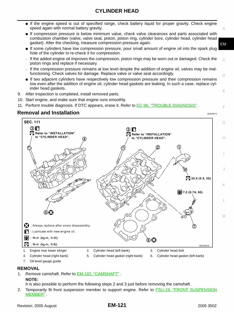
CYLINDER HEAD
EM-121
C
D
E
F
G
H
I
J
K
L
M
A
EM
Revision: 2005 August 2005 350Z
● If the engine speed is out of specified range, check battery liquid for proper gravity. Check enginespeed again with normal battery gravity.
● If compression pressure is below minimum value, check valve clearances and parts associated withcombustion chamber (valve, valve seat, piston, piston ring, cylinder bore, cylinder head, cylinder headgasket). After the checking, measure compression pressure again.
● If some cylinders have low compression pressure, pour small amount of engine oil into the spark plughole of the cylinder to re-check it for compression.
– If the added engine oil improves the compression, piston rings may be worn out or damaged. Check thepiston rings and replace if necessary.
– If the compression pressure remains at low level despite the addition of engine oil, valves may be mal-functioning. Check valves for damage. Replace valve or valve seat accordingly.
● If two adjacent cylinders have respectively low compression pressure and their compression remainslow even after the addition of engine oil, cylinder head gaskets are leaking. In such a case, replace cyl-inder head gaskets.
9. After inspection is completed, install removed parts.10. Start engine, and make sure that engine runs smoothly.11. Perform trouble diagnosis. If DTC appears, erase it. Refer to EC-96, "TROUBLE DIAGNOSIS" .
Removal and Installation ABS009YX
REMOVAL1. Remove camshaft. Refer to EM-102, "CAMSHAFT" .
NOTE:It is also possible to perform the following steps 2 and 3 just before removing the camshaft.
2. Temporarily fit front suspension member to support engine. Refer to FSU-19, "FRONT SUSPENSIONMEMBER" .
1. Engine rear lower slinger 2. Cylinder head (left bank) 3. Cylinder head bolt
4. Cylinder head (right bank) 5. Cylinder head gasket (right bank) 6. Cylinder head gasket (left bank)
7. Oil level gauge guide
SBIA0581E

EM-122
CYLINDER HEAD
Revision: 2005 August 2005 350Z
CAUTION:Temporary fitting means the status that engine is adequately stable though the hoist is releasedfrom hanging.NOTE:At the time of the start of this procedure front suspension member is removed, and cylinder head ishanged by the hoist with engine slinger installed.
3. Release the hoist from hanging, then remove the engine slinger.4. Remove the following parts:
● Fuel tube and fuel injector assembly; Refer to EM-38, "FUEL INJECTOR AND FUEL TUBE" .● Intake manifold; Refer to EM-23, "INTAKE MANIFOLD" .● Exhaust manifold; Refer to EM-25, "EXHAUST MANIFOLD AND THREE WAY CATALYST" .● Water inlet and thermostat assembly; Refer to CO-28, "WATER INLET AND THERMOSTAT ASSEM-
BLY" .● Water outlet and water pipe; Refer to CO-30, "WATER OUTLET AND WATER PIPING" .
5. Remove cylinder head bolts in reverse order as shown in the fig-ure with cylinder head bolt wrench (commercial service tool).
6. Remove cylinder head gaskets.
INSPECTION AFTER REMOVALCylinder Head Bolts Outer Diameter● Cylinder head bolts are tightened by plastic zone tightening
method. Whenever the size difference between “d1” and “d2”exceeds the limit, replace them with new one.
● If reduction of outer diameter appears in a position other than“d2”, use it as “d2” point.
PBIC2057E
Limit (“d1” – “d2”) : 0.11 mm (0.0043 in)
PBIC2480E

CYLINDER HEAD
EM-123
C
D
E
F
G
H
I
J
K
L
M
A
EM
Revision: 2005 August 2005 350Z
Cylinder Head DistortionNOTE:When performing this inspection, cylinder block distortion should be also checked. Refer to EM-162, "CYLIN-DER BLOCK DISTORTION" .1. Using scraper, wipe off oil, scale, gasket, sealant and carbon deposits from surface of cylinder head.
CAUTION:Do not allow gasket fragments to enter engine oil or engine coolant passages.
2. At each of several locations on bottom surface of cylinder head,measure the distortion in six directions.
● If it exceeds the limit, replace cylinder head.
INSTALLATION1. Install new cylinder head gaskets.2. Turn crankshaft until No. 1 piston is set at TDC.
● Crankshaft key should line up with the right bank cylinder cen-ter line as shown in the figure.
3. Install cylinder head follow the steps below to tighten cylinderhead bolts in numerical order as shown in the figure.CAUTION:If cylinder head bolts re-used, check their outer diametersbefore installation. Refer to EM-122, "Cylinder Head BoltsOuter Diameter" .
a. Apply new engine oil to threads and seat surfaces of cylinderhead bolts.
b. Tighten all cylinder head bolts.
c. Completely loosen all cylinder head bolts.
CAUTION:In step “c”, loosen bolts in reverse order of that indicated inthe figure.
d. Tighten all cylinder head bolts.
Limit : 0.1 mm (0.004 in)
SEM861E
SEM532G
: 98.1 N·m (10 kg-m, 72 ft-lb)
: 0 N·m (0 kg-m, 0 ft-lb)
: 34.3 - 44.1 N·m (3.5 - 4.4 kg-m, 26 - 32 ft-lb)
PBIC2057E

EM-124
CYLINDER HEAD
Revision: 2005 August 2005 350Z
e. Turn all bolts 90 to 95 degrees clockwise [target: 90 degrees(angle tightening)].CAUTION:Check the tightening angle by using angle wrench [SST].Avoid judgment by visual inspection without tool.● Check tightening angle indicated on angle wrench [SST] indi-
cator plate.f. Turn all bolts 90 to 95 degrees clockwise again [target: 90
degrees (angle tightening)].
4. After installing cylinder head, measure distance between frontend faces of cylinder block and cylinder head (left and rightbanks).
● If the measured value is out of the standard, re-install cylinderhead.
5. Install in the reverse order of removal after this step.
INSPECTION AFTER INSTALLATIONInspection for LeaksThe following are procedures for checking fluids leak, lubricates leak and exhaust gases leak.● Before starting engine, check oil/fluid levels including engine coolant and engine oil. If less than required
quantity, fill to the specified level. Refer to MA-12, "RECOMMENDED FLUIDS AND LUBRICANTS" .● Use procedure below to check for fuel leakage.– Turn ignition switch “ON” (with engine stopped). With fuel pressure applied to fuel piping, check for fuel
leakage at connection points.– Start engine. With engine speed increased, check again for fuel leakage at connection points.● Run engine to check for unusual noise and vibration.● Warm up engine thoroughly to make sure there is no leakage of fuel, exhaust gases, or any oil/fluids
including engine oil and engine coolant.● Bleed air from lines and hoses of applicable lines, such as in cooling system.● After cooling down engine, again check oil/fluid levels including engine oil and engine coolant. Refill to the
specified level, if necessary.
Summary of the inspection items:
* Transmission/transaxle/CVT fluid, power steering fluid, brake fluid, etc.
PBIC0888E
Standard : 14.1 - 14.9 mm (0.555 - 0.587 in)
EMQ0662D
Item Before starting engine Engine running After engine stopped
Engine coolant Level Leakage Level
Engine oil Level Leakage Level
Other oils and fluid* Level Leakage Level
Fuel Leakage Leakage Leakage
Exhaust gases — Leakage —

CYLINDER HEAD
EM-125
C
D
E
F
G
H
I
J
K
L
M
A
EM
Revision: 2005 August 2005 350Z
Disassembly and Assembly ABS009YY
NOTE:To identify 35th Anniversary, refer to GI-52, "Application Item" .
DISASSEMBLY1. Remove spark plug with spark plug wrench (commercial service tool).2. Remove valve lifter.
● Identify installation positions, and store them without mixing them up.3. Remove valve collet.
● Compress valve spring with valve spring compressor, attach-ment and adapter [SST]. Remove valve collet with magnethand.
CAUTION:When working, take care not to damage valve lifter holes.
4. Remove valve spring retainer, valve spring and valve spring seat.5. Push valve stem to combustion chamber side, and remove valve.
● Identify installation positions, and store them without mixing them up.
1. Valve lifter 2. Valve collet 3. Valve spring retainer
4. Valve spring 5. Valve oil seal 6. Valve spring seat
7. Valve guide 8. Spark plug 9. Spark plug tube
10. Cylinder head (right bank) 11. Valve seat 12. Valve (EXH)
13. Valve (INT) 14. Cylinder head (left bank)
PBIC2637E
PBIC1803E

EM-126
CYLINDER HEAD
Revision: 2005 August 2005 350Z
6. Remove valve oil seals using valve oil seal puller [SST].
7. If valve seat must be replaced, refer to EM-130, "VALVE SEAT REPLACEMENT" .8. If valve guide must be replaced, refer to EM-128, "VALVE GUIDE REPLACEMENT" .9. Remove spark plug tube, as necessary.
● Using pair of pliers, pull spark plug tube out of cylinder head. CAUTION:● Take care not to damage cylinder head.● Once removed, spark plug tube will be deformed and cannot be reused. Do not remove it unless
absolutely necessary.
ASSEMBLY1. When valve guide is removed, install it. Refer to EM-128, "VALVE GUIDE REPLACEMENT" .2. When valve seat is removed, install it. Refer to EM-130, "VALVE SEAT REPLACEMENT" .3. Install valve oil seals.
● Install with valve oil seal drift [SST] to match dimension in thefigure.
4. Install valve spring seat.5. Install valves.
NOTE:Larger diameter valves are for intake side.
6. Install valve spring (uneven pitch type).● Install narrow pitch end (paint mark) to cylinder head side
(valve spring seat side).
7. Install valve spring retainer.
PBIC0884E
Height “H” (Without valve spring seat installed)Intake and exhaust : 14.3 - 14.9 mm (0.563 - 0.587 in)
PBIC0802E
Paint mark collar
Except for 35th Anniversary : Blue
For 35th Anniversary : Purple
SEM085D

CYLINDER HEAD
EM-127
C
D
E
F
G
H
I
J
K
L
M
A
EM
Revision: 2005 August 2005 350Z
8. Install valve collet.● Compress valve spring with valve spring compressor, attach-
ment and adapter [SST]. Install valve collet with magnet hand.CAUTION:When working, take care not to damage valve lifter holes.
● Tap valve stem edge lightly with plastic hammer after installa-tion to check its installed condition.
9. Install valve lifter.● Install it in the original position.
10. Install spark plug tube.● Press-fit spark plug tube as follows:
a. Remove old liquid gasket adhering to cylinder head mounting hole.b. Apply liquid gasket to area within approximately 12 mm (0.47 in) from edge of spark plug tube press-fit
side.Use Genuine High Strength Locking Sealant or equivalent. Refer to GI-47, "RECOMMENDEDCHEMICAL PRODUCTS AND SEALANTS" .
c. Using drift, press-fit spark plug tube so that its height “H” is asspecified in the figure.
CAUTION:● When press-fitting, take care not to deform spark plug
tube.● After press-fitting, wipe off liquid gasket protruding onto
cylinder-head upper face.11. Install spark plug with spark plug wrench (commercial service
tool).
Inspection After Disassembly ABS009YZ
NOTE:To identify 35th Anniversary, refer to GI-52, "Application Item" .
VALVE DIMENSIONS● Check dimensions of each valve. For dimensions, refer to EM-
173, "Valve Dimensions" .● If dimensions are out of the standard, replace valve and check
valve seat contact. Refer to EM-130, "VALVE SEAT CONTACT".
PBIC1803E
Standard press-fit height “H”:: 38.1 - 39.1 mm (1.500 - 1.539 in)
PBIC2638E
SEM188A

EM-128
CYLINDER HEAD
Revision: 2005 August 2005 350Z
VALVE GUIDE CLEARANCEValve Stem DiameterMeasure diameter of valve stem with micrometer.
Valve Guide Inner DiameterMeasure inner diameter of valve guide with inside micrometer.
Valve Guide Clearance(Valve guide clearance) = (Valve guide inner diameter) – (Valve stem diameter)
● If it exceeds the limit, replace valve and/or valve guide. When valve guide must be replaced, refer to EM-128, "VALVE GUIDE REPLACEMENT" .
VALVE GUIDE REPLACEMENTWhen valve guide is removed, replace with oversized [0.2 mm (0.008 in)] valve guide.1. To remove valve guide, heat cylinder head to 110 to 130°C (230
to 266°F) by soaking in heated oil.
2. Drive out valve guide with a press [under a 20 kN (2 ton, 2.2 USton, 2.0 lmp ton) pressure] or hammer and suitable tool.WARNING:Cylinder head contains heat. When working, wear protec-tive equipment to avoid getting burned.
StandardIntake : 5.965 - 5.980 mm (0.2348 - 0.2354 in)Exhaust : 5.955 - 5.970 mm (0.2344 - 0.2350 in)
SEM938C
StandardIntake and Exhaust : 6.000 - 6.018 mm (0.2362 - 0.2369 in)
Valve guide clearance:Standard
Intake : 0.020 - 0.053 mm (0.0008 - 0.0021 in)Exhaust : 0.030 - 0.063 mm (0.0012 - 0.0025 in)
LimitIntake : 0.08 mm (0.003 in)Exhaust : 0.09 mm (0.004 in)
SEM008A
SEM931C

CYLINDER HEAD
EM-129
C
D
E
F
G
H
I
J
K
L
M
A
EM
Revision: 2005 August 2005 350Z
3. Using valve guide reamer (commercial service tool), ream cylin-der head valve guide hole.
4. Heat cylinder head to 110 to 130°C (230 to 266°F) by soaking inheated oil.
5. Using valve guide drift (commercial service tool), press valveguide from camshaft side to the dimensions as in the figure.
WARNING:Cylinder head contains heat. When working, wear protec-tive equipment to avoid getting burned.
6. Using valve guide reamer (commercial service tool), applyreamer finish to valve guide.
Valve guide hole diameter (for service parts):Intake and exhaust
: 10.175 - 10.196 mm (0.4006 - 0.4014 in)
SEM932C
SEM008A
Projection “L”Intake and exhaust
: 12.6 - 12.8 mm (0.496 - 0.504 in)
SEM950E
Standard:Intake and exhaust
: 6.000 - 6.018 mm (0.2362 - 0.2369 in)
SEM932C

EM-130
CYLINDER HEAD
Revision: 2005 August 2005 350Z
VALVE SEAT CONTACT● After confirming that the dimensions of valve guides and valves
are within the specifications, perform this procedure.● Apply prussian blue (or white lead) onto contacting surface of
valve seat to check the condition of the valve contact on the sur-face.
● Check if the contact area band is continuous all around the cir-cumference.
● If not, grind to adjust valve fitting and check again. If the contact-ing surface still has “NG” conditions even after the re-check,replace valve seat. Refer to EM-130, "VALVE SEAT REPLACE-MENT" .
VALVE SEAT REPLACEMENTWhen valve seat is removed, replace with oversized [0.5 mm (0.020 in)] valve seat.1. Bore out old seat until it collapses. Boring should not continue beyond the bottom face of the seat recess
in cylinder head. Set the machine depth stop to ensure this. Refer to EM-175, "Valve Seat" .CAUTION:Prevent to scratch cylinder head by excessive boring.
2. Ream cylinder head recess diameter for service valve seat.
● Be sure to ream in circles concentric to valve guide center.This will enable valve to fit correctly.
3. Heat cylinder head to 110 to 130°C (230 to 266°F) by soaking inheated oil.
4. Provide valve seats cooled well with dry ice. Force fit valve seat into cylinder head.WARNING:● Avoid directly touching cold valve seats.● Cylinder head contains heat. When working, wear protective equipment to avoid getting burned.
5. Using valve seat cutter set (commercial service tool) or valveseat grinder, finish seat to the specified dimensions. Refer toEM-175, "Valve Seat" .CAUTION:When using valve seat cutter, firmly grip cutter handle withboth hands. Then, press on the contacting surface allaround the circumference to cut in a single drive. Improperpressure on with cutter or cutting many different times mayresult in stage valve seat.
SBIA0322E
Oversize [0.5 mm (0.020 in)]Intake : 38.500 - 38.516 mm (1.5157 - 1.5164 in)Exhaust : 32.700 - 32.716 mm (1.2874 - 1.2880 in)
SEM795A
SEM008A
SEM934C

CYLINDER HEAD
EM-131
C
D
E
F
G
H
I
J
K
L
M
A
EM
Revision: 2005 August 2005 350Z
6. Using compound, grind to adjust valve fitting. 7. Check again for normal contact. Refer to EM-130, "VALVE SEAT CONTACT" .
VALVE SPRING SQUARENESS● Set try square along the side of valve spring and rotate spring.
Measure the maximum clearance between the top face of springand try square.
● If it exceeds the limit, replace valve spring.
VALVE SPRING DIMENSIONS AND VALVE SPRING PRESSURE LOAD● Check valve spring pressure at specified spring height.
Standard:
● If the installation load or load with valve open is out of the standard, replace valve spring.
Limit:
Except for 35th Anniversary : 2.1 mm (0.083 in)
For 35th Anniversary : 2.0 mm (0.079 in)
PBIC0080E
SEM113
Items Except for 35th Anniversary For 35th Anniversary
Free height 47.07 mm (1.8531 in) 45.43 mm (1.7886 in)
Installation height 37.00 mm (1.4567 in) 37.00 mm (1.4567 in)
Installation load 166 - 188 N (16.9 - 19.2 kg, 37 - 42 lb) 166 - 188 N (16.9 - 19.2 kg, 37 - 42 lb)
Height during valve open 27.2 mm (1.0709 in) 26.8 mm (1.0551 in)
Load with valve open 373 - 421 N (38.0 - 42.9 kg, 84 - 95 lb) 434 - 490 N (44.3 - 50.0 kg, 97.6 - 110.2 lb)
Identification color Blue Purple

EM-132
ENGINE ASSEMBLY
Revision: 2005 August 2005 350Z
ENGINE ASSEMBLY PFP:10001
Removal and Installation ABS009Z0
WARNING:● Situate vehicle on a flat and solid surface.● Place chocks at front and back of rear wheels.● For engines not equipped with engine slingers, attach proper slingers and bolts described in
PARTS CATALOG.CAUTION:● Always be careful to work safely, avoid forceful or uninstructed operations.● Do not start working until exhaust system and engine coolant are cool enough.● If items or work required are not covered by the engine section, refer to the applicable sections.● Always use the support point specified for lifting.● Use either 2-pole lift type or separate type lift as best you can. If board-on type is used for
unavoidable reasons, support at the rear axle jacking point with transmission jack or similar toolbefore starting work, in preparation for the backward shift of center of gravity.
● For supporting points for lifting and jacking point at rear axle, refer to GI-41, "Garage Jack andSafety Stand" .
1. Engine mounting bracket (RH) 2. Heat insulator (RH) 3. Engine mounting Insulator (RH)
4. Engine mounting insulator (LH) 5. Heat insulator (LH) 6. Engine mounting bracket (LH)
7. Harness bracket 8. Rear engine mounting member 9. Mass damper
10. Engine mounting insulator (rear) 11. Dynamic damper
PBIC2309E

ENGINE ASSEMBLY
EM-133
C
D
E
F
G
H
I
J
K
L
M
A
EM
Revision: 2005 August 2005 350Z
REMOVALOutlineAt first, remove engine and transmission assembly with front suspension member from vehicle downward.Then separate engine from transmission.
Preparation1. Release fuel pressure. Refer to EC-94, "FUEL PRESSURE RELEASE" .2. Drain engine coolant from radiator. Refer to CO-10, "Changing Engine Coolant" .
CAUTION:● Perform this step when engine is cold.● Do not spill engine coolant on drive belts.
3. Disconnect both battery cables. Refer to SC-4, "BATTERY" .4. Remove the following parts:
● Tower bar; Refer to FSU-20, "TOWER BAR" .● Engine cover; Refer to EM-18, "INTAKE MANIFOLD COLLECTOR" .● Front wiper arm and cowl top cover; Refer to EI-20, "COWL TOP" .● Undercover● Drive belts; Refer to EM-14, "DRIVE BELTS" .● Front road wheels and tires
5. Remove air cleaner case and air duct. Refer to EM-16, "AIR CLEANER AND AIR DUCT" .6. Discharge refrigerant from A/C circuit. Refer to ATC-127, "REFRIGERANT LINES" .7. Remove radiator cooling fan assembly, reservoir tank and hoses. Refer to CO-21, "COOLING FAN" and
CO-13, "RADIATOR" .
Engine Room1. Disconnect heater hose at engine-side, and fit a plug onto hose end to prevent engine coolant leak.2. Disconnect ground cable (between vehicle to left cylinder head).3. Disconnect battery positive cable harness at vehicle side and temporarily fasten it on engine. 4. Disconnect A/C piping from A/C compressor, and temporarily fasten it on vehicle with a rope.5. Remove engine room harness connectors as shown in the fig-
ure.
6. Disconnect two body ground cables.7. Disconnect brake booster vacuum hose.8. Disconnect fuel feed hose (with damper) and EVAP hose. Refer to EM-38, "FUEL INJECTOR AND FUEL
TUBE" .CAUTION:Fit plugs onto disconnected hoses to prevent fuel leak.
9. Remove reservoir tank of power steering oil pump, and piping from vehicle, and temporarily secure themon engine.CAUTION:When temporarily securing, keep the reservoir tank upright to avoid a fluid leak.
Passenger Room SideFollow procedure below to disconnect engine room harness connectors at passenger room side, and tempo-rarily secure them on engine.
PBIC1105E

EM-134
ENGINE ASSEMBLY
Revision: 2005 August 2005 350Z
1. Remove passenger-side kicking plate inner, dash side finisher, and instrument passenger panel lower.Refer to EI-35, "BODY SIDE TRIM" and IP-10, "INSTRUMENT PANEL ASSEMBLY" .
2. Disconnect engine room harness connectors at unit sides TCM(A/T models), ECM and other.
3. Disengage intermediate fixing point. Pull out engine room harnesses to engine room side, and temporarilysecure them on engine.CAUTION:● When pulling out harnesses, take care not to damage harnesses and connectors.● After temporarily securing, cover connectors with vinyl or similar material to protect against for-
eign material adhesion.
Vehicle Underbody1. Remove exhaust front tube. Refer to EX-3, "EXHAUST SYSTEM" .2. Disconnect steering lower joint at power steering gear assembly side, and release steering lower shaft.
Refer to PS-10, "STEERING COLUMN" .3. Remove propeller shaft. Refer to PR-5, "REAR PROPELLER SHAFT" .
CAUTION:Do not impact or damage propeller shaft tube.
4. Disengage shift lever and clutch operating cylinder (M/T models). Refer to MT-18, "TRANSMISSIONASSEMBLY" and CL-11, "OPERATING CYLINDER" .
5. Disengage A/T control rod at control device assembly side. Then, temporarily secure it on transmission,so that it does not sag (A/T models). Refer to AT-236, "SHIFT CONTROL SYSTEM" .
6. Remove rear plate cover from oil pan (upper). Then remove bolts fixing drive plate to torque converter (A/T models). Refer to EM-29, "OIL PAN AND OIL STRAINER" and AT-272, "TRANSMISSION ASSEM-BLY" .
7. Remove bolts fixing transmission to lower rear side of oil pan (upper). Refer to MT-18, "TRANSMISSIONASSEMBLY" (M/T models) or AT-272, "TRANSMISSION ASSEMBLY" (A/T models).
8. Remove front stabilizer. Refer to FSU-18, "STABILIZER BAR" .9. Separate steering outer sockets from steering knuckle. Refer to PS-17, "POWER STEERING GEAR AND
LINKAGE" .10. Separate transverse links from suspension member and vehicle body. Refer to FSU-13, "TRANSVERSE
LINK" .
Removal Work1. Use a manual lift table caddy (commercial service tool) or equiv-
alently rigid tool such as transmission jack. Securely supportbottom of suspension member and transmission.CAUTION:Put a piece of wood or something similar as the supportingsurface, secure a completely stable condition.
2. Remove rear engine mounting member bolts.
PBIC0883E
PBIC0804E

ENGINE ASSEMBLY
EM-135
C
D
E
F
G
H
I
J
K
L
M
A
EM
Revision: 2005 August 2005 350Z
3. Remove front suspension member mounting nuts. Refer to FSU-5, "FRONT SUSPENSION ASSEMBLY" .4. Carefully lower jack, or raise lift to remove the engine, transmission and front suspension member assem-
bly. When performing work, observe the following caution:CAUTION:● Confirm there is no interference with the vehicle.● Make sure that all connection points have been disconnected.● Keep in mind the center of the vehicle gravity changes. If necessary, use jack(s) to support the
vehicle at rear jacking point(s) to prevent it from falling it off the lift.
Separation Work1. Install engine slingers into front of cylinder head (right bank) and
rear of cylinder head (left bank).
● To protect rocker cover against damage caused by tilting ofengine slinger, insert spacer between cylinder head andengine rear lower slinger, in direction shown in the figure.NOTE:Spacer is a component part of engine rear upper slingerassembly.
2. Remove power steering oil pump from engine side. Refer to PS-29, "POWER STEERING OIL PUMP" .3. Remove engine mounting insulators (RH and LH) under side nut.4. Lift with hoist and separate engine and transmission assembly from front suspension member.
CAUTION:● Before and during this lifting, always make sure that any harnesses are left connected.● Avoid damage to and oil/grease smearing or spills onto engine mounting insulator.
5. Remove alternator. Refer to SC-21, "CHARGING SYSTEM" .6. Remove starter motor. Refer to SC-10, "STARTING SYSTEM" .7. Separate engine from transmission. Refer to MT-18, "TRANSMISSION ASSEMBLY" (M/T models) or AT-
272, "TRANSMISSION ASSEMBLY" (A/T models).8. Remove engine mounting insulators (RH and LH) and brackets (RH and LH) from engine.9. Remove rear engine mounting member and engine mounting insulator (rear) from transmission.
INSTALLATIONNote the following, and install in the reverse order of removal.● Do not allow engine mounting insulator to be damage and careful no engine oil gets on it.● For a location with a positioning pin, insert it securely into hole of mating part.● For a part with a specified installation orientation, refer to component figure in EM-132, "Removal and
Installation" .
Slinger bolts:
: 24.5 - 31.4 N·m (2.5 - 3.2 kg-m, 18 - 23 ft-lb)
PBIC2061E
KBIA1017E

EM-136
ENGINE ASSEMBLY
Revision: 2005 August 2005 350Z
● When installing engine mounting brackets (RH and LH) on cylin-der block, tighten two upper bolts (shown as “A” in the figure)first. Then tighten two lower bolts (shown as “B” in the figure).
● Make sure all engine mounting insulators are seated properly, then tighten mounting nuts.● Tighten rear engine mounting member bolts in numerical order
as shown in the figure.
PBIC2062E
PBIC2289E
PBIC2290E

ENGINE ASSEMBLY
EM-137
C
D
E
F
G
H
I
J
K
L
M
A
EM
Revision: 2005 August 2005 350Z
INSPECTION AFTER INSTALLATIONInspection for LeaksThe following are procedures for checking fluids leak, lubricates leak and exhaust gases leak.● Before starting engine, check oil/fluid levels including engine coolant and engine oil. If less than required
quantity, fill to the specified level. Refer to MA-12, "RECOMMENDED FLUIDS AND LUBRICANTS" .● Use procedure below to check for fuel leakage.– Turn ignition switch “ON” (with engine stopped). With fuel pressure applied to fuel piping, check for fuel
leakage at connection points.– Start engine. With engine speed increased, check again for fuel leakage at connection points.● Run engine to check for unusual noise and vibration.● Warm up engine thoroughly to make sure there is no leakage of fuel, exhaust gases, or any oil/fluids
including engine oil and engine coolant.● Bleed air from lines and hoses of applicable lines, such as in cooling system.● After cooling down engine, again check oil/fluid levels including engine oil and engine coolant. Refill to the
specified level, if necessary.
Summary of the inspection items:
* Transmission/transaxle/CVT fluid, power steering fluid, brake fluid, etc.
Item Before starting engine Engine running After engine stopped
Engine coolant Level Leakage Level
Engine oil Level Leakage Level
Other oils and fluid* Level Leakage Level
Fuel Leakage Leakage Leakage
Exhaust gases — Leakage —

EM-138
CYLINDER BLOCK
Revision: 2005 August 2005 350Z
CYLINDER BLOCK PFP:11010
Disassembly and Assembly ABS009Z1
NOTE:To identify 35th Anniversary, refer to GI-52, "Application Item" .

CYLINDER BLOCK
EM-139
C
D
E
F
G
H
I
J
K
L
M
A
EM
Revision: 2005 August 2005 350Z
1. Reinforcement plate 2. Drive plate (A/T models) 3. Cover
4. Gasket 5. Knock sensor 6. Cylinder block
7. Rear oil seal retainer 8. Oil jet 9. Thrust bearing
PBIC3496E

EM-140
CYLINDER BLOCK
Revision: 2005 August 2005 350Z
DISASSEMBLY1. Remove engine assembly from vehicle, and separate front suspension member and transmission from
engine. Refer to EM-132, "ENGINE ASSEMBLY" .2. Remove engine mounting brackets (RH and LH). Refer to EM-132, "ENGINE ASSEMBLY" .3. Remove exhaust manifold (right bank). Refer to EM-25, "EXHAUST MANIFOLD AND THREE WAY CAT-
ALYST" .4. Install engine sub-attachment with engine stand shaft [SST] to
right side of cylinder block.● Use spacer to engine rear side.
10. Pilot converter (A/T models) 11. Pilot bushing (M/T models) 12. Main bearing
13. Crankshaft 14. Crankshaft Key 15. Main bearing cap
16. Main bearing cap bolt 17. Main bearing beam 18. Baffle plate
19. Connecting rod bolt
(Except for 35th Anniversary)
20. Connecting rod bolt
(For 35th Anniversary)
21. Connecting rod bearing cap
22. Connecting rod bearing 23. Connecting rod 24. Snap ring
25. Piston pin 26. Piston 27. Oil ring
28. Second ring 29. Top ring 30. Flywheel (M/T models)
1. Cylinder block 2. Gasket 3. Water connector
4. Gasket 5. Cylinder block heater 6. Connector protector cap
PBIC2614E
PBIC0920E
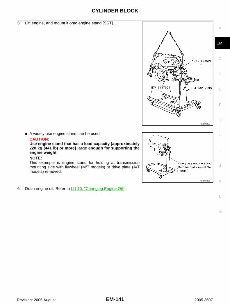
CYLINDER BLOCK
EM-141
C
D
E
F
G
H
I
J
K
L
M
A
EM
Revision: 2005 August 2005 350Z
5. Lift engine, and mount it onto engine stand [SST].
● A widely use engine stand can be used.CAUTION:Use engine stand that has a load capacity [approximately220 kg (441 lb) or more] large enough for supporting theengine weight.NOTE:This example is engine stand for holding at transmissionmounting side with flywheel (M/T models) or drive plate (A/Tmodels) removed.
6. Drain engine oil. Refer to LU-10, "Changing Engine Oil" .
PBIC0805E
PBIC0085E

EM-142
CYLINDER BLOCK
Revision: 2005 August 2005 350Z
7. Drain engine coolant by removing water drain plugs from cylin-der block both sides at “B” and “C” and cylinder block front sideat “A” as shown in the figure.
8. Remove clutch cover and clutch disc (M/T models). Refer to CL-15, "CLUTCH DISC, CLUTCH COVER" .9. Remove flywheel (M/T models) or drive plate (A/T models). Fix
crankshaft with ring gear stopper [SST], and remove mountingbolts.● Loosen mounting bolts in diagonal order.● Use TORX socket for flywheel mounting bolts (size: T55,
commercial service tool)
CAUTION:● Do not disassemble flywheel (M/T models) and drive
plate (A/T models).● Do not place drive plate (A/T models) with signal plate
facing down.● When handling signal plate, take care not to damage or
scratch it. ● Handle signal plate in a manner that prevents it from
becoming magnetized.
10. Remove cylinder head. Refer to EM-120, "CYLINDER HEAD" .11. Remove knock sensor.
CAUTION:Carefully handle sensor avoiding shocks.
PBIC2610E
PBIC1109E
SEM760G

CYLINDER BLOCK
EM-143
C
D
E
F
G
H
I
J
K
L
M
A
EM
Revision: 2005 August 2005 350Z
12. Remove pilot bushing (M/T models) or pilot converter (A/T mod-els) using pilot bushing puller [SST] or suitable tool as neces-sary.
13. Remove rear oil seal retainer.● Remove by inserting screwdriver between main bearing cap and rear oil seal retainer.CAUTION:If rear oil seal retainer is removed, replace it with new one.NOTE:Regard both rear oil seal and retainer as an assembly.
14. Remove baffle plate from main bearing beam.15. Remove piston and connecting rod assembly as follows:
● Before removing piston and connecting rod assembly, check the connecting rod side clearance. Referto EM-158, "CONNECTING ROD SIDE CLEARANCE" .
a. Position crankshaft pin corresponding to connecting rod to be removed onto the bottom dead center.b. Remove connecting rod bearing cap.c. Using hammer handle or similar tool, push piston and connect-
ing rod assembly out to the cylinder head side.CAUTION:Be careful not to damage the cylinder wall and crankshaftpin, resulting from an interference of the connecting rod bigend.
16. Remove connecting rod bearings from connecting rod and connecting rod bearing cap.CAUTION:Identify installation position, and store them without mixing them up.
17. Remove piston rings form piston. ● Before removing piston rings, check the piston ring side clearance. Refer to EM-159, "PISTON RING
SIDE CLEARANCE" .● Use piston ring expander (commercial service tool).CAUTION:● When removing piston rings, be careful not to damage
piston.● Be careful not to damage piston rings by expanding them
excessively.
18. Remove piston from connecting rod as follows:
SEM005G
EMQ0191D
PBIC0087E
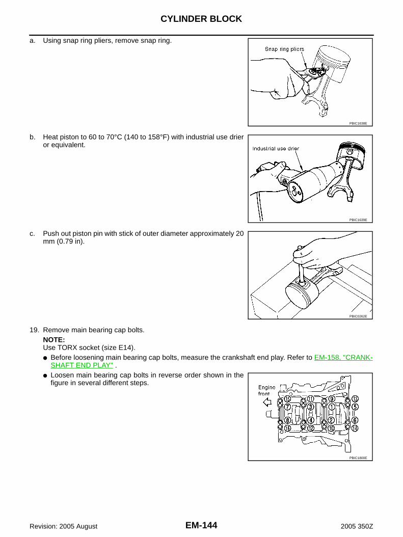
EM-144
CYLINDER BLOCK
Revision: 2005 August 2005 350Z
a. Using snap ring pliers, remove snap ring.
b. Heat piston to 60 to 70°C (140 to 158°F) with industrial use drieror equivalent.
c. Push out piston pin with stick of outer diameter approximately 20mm (0.79 in).
19. Remove main bearing cap bolts.NOTE:Use TORX socket (size E14).● Before loosening main bearing cap bolts, measure the crankshaft end play. Refer to EM-158, "CRANK-
SHAFT END PLAY" .● Loosen main bearing cap bolts in reverse order shown in the
figure in several different steps.
PBIC1638E
PBIC1639E
PBIC0262E
PBIC1800E

CYLINDER BLOCK
EM-145
C
D
E
F
G
H
I
J
K
L
M
A
EM
Revision: 2005 August 2005 350Z
20. Remove main bearing beam.
21. Remove main bearing caps.● Using main bearing cap bolts, remove main bearing cap while
shaking it back-and-forth.
22. Remove crankshaft.23. Remove main bearings and thrust bearings from cylinder block and main bearing caps.
CAUTION:Identify installation positions, and store them without mixing them up.
24. Remove oil jet.
ASSEMBLY1. Fully air-blow engine coolant and engine oil passages in cylinder block, cylinder bore and crankcase to
remove any foreign material.CAUTION:Use a goggles to protect your eye.
2. Install each plug to cylinder block as shown in the figure.● Apply sealant to the thread of water drain plugs “A”, “B” and
“C”.Use Genuine RTV Silicone Sealant or equivalent. Refer toGI-47, "RECOMMENDED CHEMICAL PRODUCTS ANDSEALANTS" .
● Apply sealant to the thread of plugs “D” and “E”.Use Genuine High Strength Thread Locking Sealant orequivalent. Refer to GI-47, "RECOMMENDED CHEMICALPRODUCTS AND SEALANTS" .
● Apply sealant to the thread of plug “F”.Use Anaerobic Liquid Gasket or equivalent. Refer to GI-47, "RECOMMENDED CHEMICAL PRODUCTS AND SEAL-ANTS" .
● Replace washers with new one.
PBIC0881E
EMQ0195D
PBIC2610E

EM-146
CYLINDER BLOCK
Revision: 2005 August 2005 350Z
● Tighten each plug as specified below.
3. Install oil jet.● Insert oil jet dowel pin into cylinder block dowel pin hole, and
tighten mounting bolts.
4. Install main bearings and thrust bearings as follows:a. Remove dust, dirt, and engine oil on bearing mating surfaces of cylinder block and main bearing caps.b. Install thrust bearings to the both sides of the No. 3 journal hous-
ing on cylinder block and main bearing cap.● Install thrust bearings with the oil groove facing crankshaft
arm (outside). ● Install thrust bearing with a protrusion on one end on cylinder
block, and thrust bearing with a protrusion at center on cap.Align each protrusion with mating notch.
c. Install main bearings paying attention to the direction.● Main bearing with oil hole and groove goes on cylinder block.
The one without them goes on main bearing cap.● Before installing main bearings, apply engine oil to the bear-
ing surface (inside). Do not apply engine oil to the back sur-face, but thoroughly clean it.
● When installing, align main bearing stopper protrusion to cut-out of cylinder block and main bearing caps.
● Ensure the oil holes on cylinder block and those on the corre-sponding bearing are aligned.
5. Install crankshaft to cylinder block.● While turning crankshaft by hand, check that it turns smoothly.
6. Install main bearing cap.
Part Washer Tightening torque
A No 9.8 N·m (1.0 kg-m, 87 in-lb)
B No 19.6 N·m (2.0 kg-m, 14 ft-lb)
C No 19.6 N·m (2.0 kg-m, 14 ft-lb)
D Yes 12.3 N·m (1.3 kg-m, 9 ft-lb)
E Yes 62 N·m (6.3 kg-m, 46 ft-lb)
F Yes 62 N·m (6.3 kg-m, 46 ft-lb)
PBIC0898E
PBIC0807E
PBIC2489E

CYLINDER BLOCK
EM-147
C
D
E
F
G
H
I
J
K
L
M
A
EM
Revision: 2005 August 2005 350Z
● Main bearing caps are identified by identification mark cast onthem. For installation, face front mark to front side.
NOTE:Main bearing cap cannot be replaced as a single part, because itis machined together with cylinder block.
7. Install main bearing beam.● Install main bearing beam with front mark facing downward (oil pan side).● Install main bearing beam with front mark facing front of
engine.
8. Inspect the outer diameter of main bearing cap bolt. Refer to EM-167, "MAIN BEARING CAP BOLTOUTER DIAMETER" .
9. Tighten main bearing cap bolts in numerical order as shown inthe figure as follows:
a. Apply new engine oil to threads and seat surfaces of main bear-ing cap bolts.
b. Tighten main bearing cap bolts in several different steps.
c. Turn all bolts another 90 to 95 degrees clockwise [Target: 90degrees (Angle tightening)].CAUTION:Use angle wrench [SST: KV10112100 (BT8653-A)] to checktightening angle. Do not make judgment by visual inspec-tion. ● After installing main bearing cap bolts, make sure that crank-
shaft can be rotated smoothly by hand.● Check the crankshaft end play. Refer to EM-158, "CRANK-
SHAFT END PLAY" .
10. Install piston to connecting rod as follows: a. Using snap ring pliers, install new snap ring to the groove of piston rear side.
● Insert it fully into groove to install.b. Install piston to connecting rod.
SEM456G
PBIC0881E
: 32.3 - 38.3 N·m (3.3 - 3.9 kg-m, 24 - 28 ft-lb)
PBIC1800E
PBIC0921E

EM-148
CYLINDER BLOCK
Revision: 2005 August 2005 350Z
● Using industrial use drier or similar tool, heat piston until piston pin can be pushed in by hand withoutexcess force [approx. 60 to 70°C (140 to 158°F)]. From the front to the rear, insert piston pin into pistonand connecting rod.
● Assemble so that the front mark on the piston head and thecylinder number on connecting rod are positioned as shown inthe figure.
NOTE:Figure shows the piston except for 35th Anniversary. The frontmarks of 35th Anniversary are 2 punched.
c. Install new snap ring to the groove of the piston front side. ● Insert it fully into groove to install.● After installing, make sure that connecting rod moves
smoothly.
11. Using piston ring expander (commercial service tool), install pis-ton rings.CAUTION:● When installing piston rings, be careful not to damage
piston.● Be careful not to damage piston rings by expending them
excessively.
● If there is stamped mark on ring, mount it with marked sideup.NOTE:If there is no stamp on ring except second ring, no specific ori-entation is required for installation.
● Position each ring with the gap as shown in the figure refer-ring to the piston front mark.NOTE:Figure shows models except for 35th Anniversary. The frontmarks of 35th Anniversary are 2 punched.
● Check the piston ring side clearance. Refer to EM-159, "PISTON RING SIDE CLEARANCE" .12. Install connecting rod bearings to connecting rod and connecting rod bearing cap.
● Before installing connecting rod bearings, apply engine oil to the bearing surface (inside). Do not applyengine oil to the back surface, but thoroughly clean it.
SEM838F
PBIC0087E
Stamped mark:
Except for 35th AnniversaryTop ring : —Second ring : R
For 35th AnniversaryTop ring : —Second ring : —
PBIC3497E
PBIC0808E

CYLINDER BLOCK
EM-149
C
D
E
F
G
H
I
J
K
L
M
A
EM
Revision: 2005 August 2005 350Z
● When installing, align connecting rod bearing stopper protru-sion with cutout of connecting rods and connecting rod bear-ing caps to install.
● Ensure the oil hole on connecting rod and that on the corre-sponding bearing are aligned.
13. Install piston and connecting rod assembly to crankshaft. ● Position crankshaft pin corresponding to connecting rod to be installed onto the bottom dead center. ● Apply engine oil sufficiently to the cylinder bore, piston and crankshaft pin journal.● Match the cylinder position with the cylinder number on connecting rod to install. ● Be sure that front mark on piston head is facing front of engine.● Using piston ring compressor [SST] or suitable tool, install
piston with the front mark on the piston head facing the frontof engine.
CAUTION:Be careful not to damage the cylinder wall and crankshaftpin, resulting from an interference of the connecting rod bigend.
14. Install connecting rod bearing cap.● Match the stamped cylinder number marks on connecting rod
with those on connecting rod bearing cap to install.● Be sure that front mark on connecting rod bearing cap is fac-
ing front of engine.
15. Inspect the outer diameter of connecting rod bolt. (Except for 35th Anniversary) Refer to EM-167, "CON-NECTING ROD BOLT OUTER DIAMETER (EXCEPT FOR 35TH ANNIVERSARY)" .CAUTION:Do not reuse connecting rod bolt for 35th Anniversary. Replace it with a new one.
16. Tighten connecting rod bolts as follows:a. Apply engine oil to the threads and seats of connecting rod bolts. b. Tighten connecting rod bolts.
PBIC2067E
SEM620
PBIC0809E
: 18.6 - 20.6 N·m (1.9 - 2.1 kg-m, 14 - 15 ft-lb)
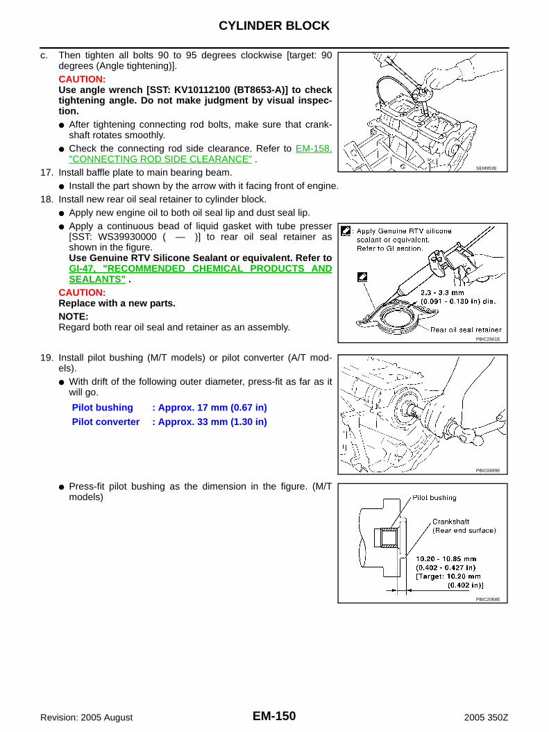
EM-150
CYLINDER BLOCK
Revision: 2005 August 2005 350Z
c. Then tighten all bolts 90 to 95 degrees clockwise [target: 90degrees (Angle tightening)].CAUTION:Use angle wrench [SST: KV10112100 (BT8653-A)] to checktightening angle. Do not make judgment by visual inspec-tion. ● After tightening connecting rod bolts, make sure that crank-
shaft rotates smoothly.● Check the connecting rod side clearance. Refer to EM-158,
"CONNECTING ROD SIDE CLEARANCE" .17. Install baffle plate to main bearing beam.
● Install the part shown by the arrow with it facing front of engine.18. Install new rear oil seal retainer to cylinder block.
● Apply new engine oil to both oil seal lip and dust seal lip.● Apply a continuous bead of liquid gasket with tube presser
[SST: WS39930000 ( — )] to rear oil seal retainer asshown in the figure.Use Genuine RTV Silicone Sealant or equivalent. Refer toGI-47, "RECOMMENDED CHEMICAL PRODUCTS ANDSEALANTS" .
CAUTION:Replace with a new parts.NOTE:Regard both rear oil seal and retainer as an assembly.
19. Install pilot bushing (M/T models) or pilot converter (A/T mod-els).● With drift of the following outer diameter, press-fit as far as it
will go.
● Press-fit pilot bushing as the dimension in the figure. (M/Tmodels)
SEM953E
PBIC2661E
Pilot bushing : Approx. 17 mm (0.67 in)Pilot converter : Approx. 33 mm (1.30 in)
PBIC0899E
PBIC2068E

CYLINDER BLOCK
EM-151
C
D
E
F
G
H
I
J
K
L
M
A
EM
Revision: 2005 August 2005 350Z
● Press-fit pilot converter with its chamfer facing crankshaft asshown in the figure. (A/T models)
20. Install knock sensor.● Install knock sensor so that connector faces front of engine.● After installing knock sensor, connect harness connector, and
lay it out to rear of engine.CAUTION:● Do not tighten mounting bolts while holding connector. ● If any impact by dropping is applied to knock sensor,
replace it with new one.NOTE:● Make sure that there is no foreign material on the cylinder
block mating surface and the back surface of knock sensor. ● Make sure that knock sensor does not interfere with other parts.
21. Note the following, assemble in the reverse order of disassembly after this step.Flywheel (M/T models)● When installing flywheel to crankshaft, be sure to correctly
align crankshaft side dowel pin and flywheel side dowel pinhole.CAUTION:If these are not aligned correctly, engine runs roughlyand “MIL” turns on.
● There is a mating mark on the clutch cover side of flywheel.Refer it during installation.
SEM537E
PBIC0810E
PBIC1110E
PBIC1112E

EM-152
CYLINDER BLOCK
Revision: 2005 August 2005 350Z
● Holding ring gear with ring gear stopper [SST], tighten secur-ing bolts with TORX socket (size: T55, commercial servicetool).
● Tighten the mounting bolts crosswise over several times.
Drive plate (A/T models)● When installing drive plate to crankshaft, be sure to correctly align crankshaft side dowel pin and drive
plate side dowel pin hole.CAUTION:If these are not aligned correctly, engine runs roughly and “MIL” turns on.
● Install drive plate and reinforcement plate as shown in the fig-ure.
● Holding ring gear with ring gear stopper [SST: KV10117700(J44716)].
● Tighten the mounting bolts crosswise over several times.
PBIC1109E
PBIC0910E

CYLINDER BLOCK
EM-153
C
D
E
F
G
H
I
J
K
L
M
A
EM
Revision: 2005 August 2005 350Z
How to Select Piston and Bearing ABS009Z2
NOTE:To identify 35th Anniversary, refer to GI-52, "Application Item" .
DESCRIPTION
*: For the service parts, the grade for fitting cannot be selected between piston pin and connecting rod. (Only “0” grade is available.) Theinformation at the shipment from the plant is described as a reference.
● The identification grade stamped on each part is the grade for the dimension measured in new condition.This grade cannot apply to reused parts.
● For reused or repaired parts, measure the dimension accurately. Determine the grade by comparing themeasurement with the values of each selection table.
● For details of the measurement method of each part, the reuse standards and the selection method of theselective fitting parts, refer to the text.
HOW TO SELECT PISTONWhen New Cylinder Block is UsedCheck the cylinder bore grade (“1”, “2” or “3”) on rear side of cylinderblock, and select piston of the same grade.NOTE:Piston is available with piston pin as a set for the service part. (Only“0” grade piston pin is available.)
When Cylinder Block is Reused1. Measure the cylinder bore inner diameter. Refer to EM-163, "Cylinder Bore Inner Diameter" .2. Determine the bore grade by comparing the measurement with
the values under the cylinder bore inner diameter of the “PistonSelection Table”.NOTE:Figure shows the piston except for 35th Anniversary. The frontmarks of 35th Anniversary are 2 punched.
Selection points Selection parts Selection items Selection methods
Between cylinder block to crankshaft
Main bearingMain bearing grade(bearing thickness)
Determined by match of cylin-der block bearing housing grade (inner diameter of hous-ing) and crankshaft journal grade (outer diameter of jour-nal)
Between crankshaft to connect-ing rod
Connecting rod bearingConnecting rod bearing grade (bearing thickness)
Combining service grades for connecting rod big end diame-ter and crankshaft pin outer diameter determine connecting rod bearing selection.
Between cylinder block to pis-ton
Piston and piston pin assembly(Piston is available together with piston pin as assembly.)
Piston grade(piston skirt diameter)
Piston grade = cylinder bore grade (inner diameter of bore)
Between piston to connecting rod*
— — —
SEM756G
PBIC0812E

EM-154
CYLINDER BLOCK
Revision: 2005 August 2005 350Z
3. Select piston of the same grade.
Piston Selection TableUnit: mm (in)
NOTE:● Piston is available together with piston pin as assembly.● Piston pin (piston pin hole) grade is provided only for the parts installed at the plant. For service parts, no
piston pin grades can be selected. (Only “0” grade is available.)● No second grade mark is available on piston.
HOW TO SELECT CONNECTING ROD BEARINGWhen New Connecting Rod and Crankshaft are UsedCheck pin diameter grade (“0”, “1” or “2”) on front of crankshaft, andselect connecting rod bearing of the same grade.NOTE:There is no grading for connecting rod big end diameter.
When Crankshaft and Connecting Rod are Reused1. Measure the connecting rod big end diameter. Refer to EM-161, "CONNECTING ROD BIG END DIAME-
TER" .2. Make sure that the connecting rod big end diameter is within the standard value.3. Measure the crankshaft pin journal diameter. Refer to EM-164, "CRANKSHAFT PIN JOURNAL DIAME-
TER" .4. Determine the grade of crankshaft pin diameter grade by corresponding to the measured dimension in
“Crankshaft pin journal diameter” column of “Connecting Rod Bearing Selection Table”.5. Select connecting rod bearing of the same grade.
Connecting Rod Bearing Selection TableUnit: mm (in)
Unit: mm (in)
Undersize Bearings Usage Guide● When the specified connecting rod bearing oil clearance is not obtained with standard size connecting rod
bearings, use undersize (US) bearings.● When using undersize (US) bearing, measure the connecting rod bearing inner diameter with bearing
installed, and grind crankshaft pin so that the connecting rod bearing oil clearance satisfies the standard.
Grade 1 2 (or no mark) 3
Cylinder bore inner diameter95.500 - 95.510
(3.7598 - 3.7602)95.510 - 95.520
(3.7602- 3.7606)95.520 - 95.530
(3.7606 - 3.7610)
Piston skirt diameter95.480 - 95.490
(3.7590 - 3.7594)95.490 - 95.500
(3.7594 - 3.7598)95.500 - 95.510
(3.7598 - 3.7602)
SEM452G
Connecting rod big end diameter 55.000 - 55.013 (2.1654 - 2.1659)
Crankshaft Connecting rod bearing
Crankshaft pin journal diameter Grade (Mark) Dimension (Bearing thickness range) Bearing grade No. Color
51.968 - 51.974 (2.0460 - 2.0462) 0 1.500 - 1.503 (0.0591 - 0.0592) STD 0 Black
51.962 - 51.968 (2.0457 - 2.0460) 1 1.503 - 1.506 (0.0592 - 0.0593) STD 1 Brown
51.956 - 51.962 (2.0455 - 2.0457) 2 1.506 - 1.509 (0.0593 - 0.0594) STD 2 Green

CYLINDER BLOCK
EM-155
C
D
E
F
G
H
I
J
K
L
M
A
EM
Revision: 2005 August 2005 350Z
CAUTION:In grinding crankshaft pin to use undersize bearings, keepthe fillet R [1.5 mm (0.059 in)].
Bearing undersize tableUnit: mm (in)
HOW TO SELECT MAIN BEARINGWhen New Cylinder Block and Crankshaft are Used1. “Main Bearing Selection Table” rows correspond to bearing
housing grade on rear left side of cylinder block.
2. “Main Bearing Selection Table” columns correspond to journaldiameter grade on front side of crankshaft.
3. Select main bearing grade at the point where selected row and column meet in “Main Bearing SelectionTable”.
When Cylinder Block and Crankshaft are Reused1. Measure cylinder block main bearing housing inner diameter and crankshaft main journal diameter. Refer
to EM-162, "MAIN BEARING HOUSING INNER DIAMETER" and EM-164, "CRANKSHAFT MAINJOURNAL DIAMETER" .
2. Correspond the measured dimension in “Cylinder block main bearing housing inner diameter” row of“Main Bearing Selection Table”.
3. Correspond the measured dimension in “Crankshaft main journal diameter” column of “Main BearingSelection Table”.
4. Select main bearing grade at the point where selected row and column meet in following selection table.
PBIC1908E
Size Thickness
US 0.25 (0.0098) 1.626 - 1.634 (0.0640 - 0.0643)
SEM756G
SEM452G

EM-156
CYLINDER BLOCK
Revision: 2005 August 2005 350Z
Main Bearing Selection Table
PBIC1981E

CYLINDER BLOCK
EM-157
C
D
E
F
G
H
I
J
K
L
M
A
EM
Revision: 2005 August 2005 350Z
Main Bearing Grade Table (All Journals)
Undersize Bearing Usage Guide● When the specified main bearing oil clearance is not obtained with standard size main bearings, use
underside (US) bearing.● When using undersize (US) bearing, measure the main bearing inner diameter with bearing installed, and
grind main journal so that the main bearing oil clearance satisfies the standard.CAUTION:In grinding crankshaft main journal to use undersize bear-ings, keep the fillet R [1.5 mm (0.059 in)].
Bearing undersize tableUnit: mm (in)
Grade numberThickness
Unit: mm (in)Width
Unit: mm (in)Identification color Remarks
0 2.000 - 2.003 (0.0787 - 0.0789)
19.9 - 20.1 (0.783 - 0.791)
Black
Grade and color are the same for upper and lower bearings.
1 2.003 - 2.006 (0.0789 - 0.0790) Brown
2 2.006 - 2.009 (0.0790 - 0.0791) Green
3 2.009 - 2.012 (0.0791 - 0.0792) Yellow
4 2.012 - 2.015 (0.0792 - 0.0793) Blue
5 2.015 - 2.018 (0.0793 - 0.0794) Pink
6 2.018 - 2.021 (0.0794 - 0.0796) Purple
7 2.021 - 2.024 (0.0796 - 0.0797) White
01UPR 2.003 - 2.006 (0.0789 - 0.0790) Brown
Grade and color are different for upper and lower bearings.
LWR 2.000 - 2.003 (0.0787 - 0.0789) Black
12UPR 2.006 - 2.009 (0.0790 - 0.0791) Green
LWR 2.003 - 2.006 (0.0789 - 0.0790) Brown
23UPR 2.009 - 2.012 (0.0791 - 0.0792) Yellow
LWR 2.006 - 2.009 (0.0790 - 0.0791) Green
34UPR 2.012 - 2.015 (0.0792 - 0.0793) Blue
LWR 2.009 - 2.012 (0.0791 - 0.0792) Yellow
45UPR 2.015 - 2.018 (0.0793 - 0.0794) Pink
LWR 2.012 - 2.015 (0.0792 - 0.0793) Blue
56UPR 2.018 - 2.021 (0.0794 - 0.0796) Purple
LWR 2.015 - 2.018 (0.0793 - 0.0794) Pink
67UPR 2.021 - 2.024 (0.0796 - 0.0797) White
LWR 2.018 - 2.021 (0.0794 - 0.0796) Purple
PBIC1908E
Size Thickness
US 0.25 (0.0098) 2.132 - 2.140 (0.0839 - 0.0843)

EM-158
CYLINDER BLOCK
Revision: 2005 August 2005 350Z
Inspection After Disassembly ABS009Z3
NOTE:To identify 35th Anniversary, refer to GI-52, "Application Item" .
CRANKSHAFT END PLAY● Measure the clearance between thrust bearings and crankshaft
arm when crankshaft is moved fully forward or backward withdial indicator.
● If the measured value exceeds the limit, replace thrust bearings,and measure again. If it still exceeds the limit, replace crank-shaft also.
CONNECTING ROD SIDE CLEARANCE● Measure the side clearance between connecting rod and crank-
shaft arm with feeler gauge.
● If the measured value exceeds the limit, replace connecting rod,and measure again. If it still exceeds the limit, replace crank-shaft also.
PISTON TO PISTON PIN OIL CLEARANCEPiston Pin Hole DiameterMeasure the inner diameter of piston pin hole with inside microme-ter.
Piston Pin Outer DiameterMeasure the outer diameter of piston pin with micrometer.
Piston to Piston Pin Oil Clearance(Piston to piston pin oil clearance) = (Piston pin hole diameter) – (Piston pin outer diameter)
Standard : 0.10 - 0.25 mm (0.0039 - 0.0098 in)Limit : 0.30 mm (0.0118 in)
EMQ0196D
Standard : 0.20 - 0.35 mm (0.0079 - 0.0138 in)Limit : 0.40 mm (0.0157 in)
PBIC0815E
Standard : 21.993 - 22.005 mm (0.8659 - 0.8663 in)
PBIC0116E
Standard : 21.989 - 22.001 mm (0.8657 - 0.8662 in)
PBIC0117E

CYLINDER BLOCK
EM-159
C
D
E
F
G
H
I
J
K
L
M
A
EM
Revision: 2005 August 2005 350Z
● If the calculated value is out of the standard, replace piston and piston pin assembly.● When replacing piston and piston pin assembly, refer to EM-153, "HOW TO SELECT PISTON" .
NOTE:● Piston is available together with piston pin as assembly.● Piston pin (piston pin hole) grade is provided only for the parts installed at the plant. For service parts,
no piston pin grades can be selected. (Only “0” grade is available.)
PISTON RING SIDE CLEARANCE● Measure the side clearance of piston ring and piston ring groove
with feeler gauge.
● If the measured value exceeds the limit (or exceeding the standard in the case of oil ring except for 35th
Anniversary), replace piston ring, and measure again. If it still exceeds the limit (or exceeding the stan-dard in the case of oil ring except for 35th Anniversary), replace piston also.
Standard : 0.002 - 0.006 mm (0.0001 - 0.0002 in)
Standard:
Except for 35th AnniversaryTop ring : 0.045 - 0.080 mm (0.0018 - 0.0031 in)2nd ring : 0.030 - 0.070 mm (0.0012 - 0.0028 in)Oil ring : 0.065 - 0.135 mm (0.0026 - 0.0053 in)
For 35th AnniversaryTop ring : 0.045 - 0.080 mm (0.0018 - 0.0031 in)2nd ring : 0.030 - 0.070 mm (0.0012 - 0.0028 in)Oil ring : 0.065 - 0.135 mm (0.0026 - 0.0053 in)
Limit:
Except for 35th Anniversary Top ring : 0.11 mm (0.0043 in) 2nd ring : 0.10 mm (0.0039 in) Oil ring : —
For 35th Anniversary Top ring : 0.11 mm (0.0043 in) 2nd ring : 0.10 mm (0.0039 in) Oil ring : 0.17 mm (0.0067 in)
SEM024AA

EM-160
CYLINDER BLOCK
Revision: 2005 August 2005 350Z
PISTON RING END GAP● Make sure that cylinder bore inner diameter is within the specifi-
cation. Refer to EM-163, "Cylinder Bore Inner Diameter" .● Lubricate with new engine oil to piston and piston ring, and then
insert piston ring until middle of cylinder with piston, and mea-sure the piston ring end gap with feeler gauge.
● If the measured value exceeds the limit, replace piston ring, and measure again. If it still exceeds the limit,re-bore cylinder and use oversize piston and piston rings.
CONNECTING ROD BEND AND TORSION● Check with connecting rod aligner.
● If it exceeds the limit, replace connecting rod assembly.
Standard:
Except for 35th AnniversaryTop ring : 0.23 - 0.33 mm (0.0091 - 0.0130 in)2nd ring : 0.33 - 0.48 mm (0.0130 - 0.0189 in)Oil ring : 0.20 - 0.50 mm (0.0079 - 0.0197 in)
For 35th AnniversaryTop ring : 0.23 - 0.33 mm (0.0091 - 0.0130 in)2nd ring : 0.23 - 0.33 mm (0.0091 - 0.0130 in)Oil ring : 0.20 - 0.50 mm (0.0079 - 0.0197 in)
Limit:
Except for 35th AnniversaryTop ring : 0.54 mm (0.0213 in)
2nd ring : 0.80 mm (0.0315 in)Oil ring : 0.95 mm (0.0374 in)
For 35th AnniversaryTop ring : 0.54 mm (0.0213 in)2nd ring : 0.53 mm (0.0209 in)Oil ring : 0.85 mm (0.0335 in)
PBIC0118E
Bend:Limit : 0.15 mm (0.0059 in) per 100 mm (3.94 in) length
Torsion:Limit : 0.30 mm (0.0118 in) per 100 mm (3.94 in) length
PBIC2077E

CYLINDER BLOCK
EM-161
C
D
E
F
G
H
I
J
K
L
M
A
EM
Revision: 2005 August 2005 350Z
CONNECTING ROD BIG END DIAMETER● Install connecting rod bearing cap without installing connecting
rod bearing, and tightening connecting rod bolts to the specifiedtorque. Refer to EM-145, "ASSEMBLY" for the tightening pro-cedure.
● Measure the inner diameter of connecting rod big end withinside micrometer.
● If out of the standard, replace connecting rod assembly.
CONNECTING ROD BUSHING OIL CLEARANCEConnecting Rod Bushing Inner DiameterMeasure the inner diameter of connecting rod bushing with insidemicrometer.
Piston Pin Outer DiameterMeasure the outer diameter of piston pin with micrometer.
Connecting Rod Bushing Oil Clearance(Connecting rod bushing oil clearance) = (Connecting rod bushing inner diameter) – (Piston pin outer diame-ter)
● If the measured value exceeds the limit, replace connecting rod assembly and/or piston and piston pinassembly.
● If replacing piston and piston pin assembly, refer to EM-153, "HOW TO SELECT PISTON" .● If replacing connecting rod assembly, refer to EM-165, "CONNECTING ROD BEARING OIL CLEAR-
ANCE" to select the connecting rod bearing.
Standard : 55.000 - 55.013 mm (2.1654 - 2.1659 in)
PBIC1641E
Standard : 22.000 - 22.012 mm (0.8661 - 0.8666 in)
PBIC0120E
Standard : 21.989 - 22.001 mm (0.8657 - 0.8662 in)
PBIC0117E
Standard : 0.005 - 0.017 mm (0.0002 - 0.0007 in)Limit : 0.030 mm (0.0012 in)

EM-162
CYLINDER BLOCK
Revision: 2005 August 2005 350Z
Factory installed parts grading:● Service parts apply only to grade “0”.
Unit: mm (in)
*: After installing in connecting rod
NOTE:Figure shows the piston except for 35th Anniversary. The frontmarks of 35th Anniversary are 2 punched.
CYLINDER BLOCK DISTORTION● Using scraper, remove gasket on the cylinder block surface, and also remove engine oil, scale, carbon, or
other contamination. CAUTION:Be careful not to allow gasket flakes to enter engine oil or engine coolant passages.
● Measure the distortion on the cylinder block upper face at somedifferent points in six directions with straightedge and feelergauge.
● If it exceeds the limit, replace cylinder block.
MAIN BEARING HOUSING INNER DIAMETER● Install main bearing caps and main bearing beam without install-
ing main bearings, and tighten main bearing cap bolts to thespecified torque. Refer to EM-145, "ASSEMBLY" for the tight-ening procedure.
● Measure the inner diameter of main bearing housing with boregauge.
● If out of the standard, replace cylinder block and main bearingcaps as assembly.NOTE:Cylinder block cannot be replaced as a single part, because it ismachined together with main bearing caps.
Grade 0 1
Connecting rod bushing inner diameter *
22.000 - 22.006 (0.8661 - 0.8664)
22.006 - 22.012 (0.8664 - 0.8666)
Piston pin hole diameter 21.993 - 21.999 (0.8659 - 0.8661)
21.999 - 22. 005 (0.8661 - 0.8663)
Piston pin outer diameter 21.989 - 21.995 (0.8657- 0.8659)
21.995 - 22.001 (0.8659 - 0.8662)
PBIC0809E
PBIC0812E
Limit : 0.1 mm (0.004 in)
SEM123C
Standard : 63.993 - 64.017 mm (2.5194 - 2.5203 in)
PBIC1643E

CYLINDER BLOCK
EM-163
C
D
E
F
G
H
I
J
K
L
M
A
EM
Revision: 2005 August 2005 350Z
PISTON TO CYLINDER BORE CLEARANCECylinder Bore Inner Diameter● Using bore gauge, measure cylinder bore for wear, out-of-round
and taper at six different points on each cylinder. (“X” and “Y”directions at “A”, “B” and “C”) (“X” is in longitudinal direction ofengine)
● If the measured value exceeds the limit, or if there are scratchesand/or seizure on the cylinder inner wall, hone or re-bore theinner wall.
● Oversize piston is provided. When using oversize piston, re-bore cylinder so that the clearance of the piston-to-cylinder boresatisfies the standard.CAUTION:When using oversize piston, use over size pistons for allcylinders with oversize piston rings.
Piston Skirt DiameterMeasure the outer diameter of piston skirt with micrometer.
Piston to Cylinder Bore ClearanceCalculate by piston skirt diameter and cylinder bore inner diameter (direction “Y”, position “B”).(Clearance) = (Cylinder bore inner diameter) – (Piston skirt diameter).
● If calculated value exceeds the limit, replace piston and piston pin assembly. Refer to EM-153, "HOW TOSELECT PISTON" .
Re-boring Cylinder Bore1. Cylinder bore size is determined by adding piston to cylinder bore clearance to piston skirt diameter.
Standard inner diameter:95.500 - 95.530 mm (3.7598 - 3.7610 in)
Wear limit:0.2 mm (0.008 in)
Out-of-round (Difference between “X” and “Y”):0.015 mm (0.0006 in)
Taper limit (Difference between “A” and “C”): 0.01 mm (0.0004 in)
Oversize (OS) : 0.2 mm (0.008 in)
PBIC0923E
SEM843E
Measure point: Distance from the top 41.0 mm (1.614 in)
Standard: 95.480 - 95.510 mm (3.7590 - 3.7602 in)
PBIC0125E
Standard : 0.010 - 0.030 mm (0.0004 - 0.0012 in)Limit : 0.08 mm (0.0031 in)
Re-bored size calculation: D = A + B – Cwhere,
D: Bored diameterA: Piston skirt diameter as measured

EM-164
CYLINDER BLOCK
Revision: 2005 August 2005 350Z
2. Install main bearing caps and main bearing beam, and tighten to the specified torque. Otherwise, cylinderbores may be distorted in final assembly.
3. Cut cylinder bores.NOTE:● When any cylinder needs boring, all other cylinders must also be bored.● Do not cut too much out of cylinder bore at a time. Cut only 0.05 mm (0.0020 in) or so in diameter at a
time.4. Hone cylinders to obtain the specified piston to cylinder bore clearance.5. Measure finished cylinder bore for the out-of-round and taper.
NOTE:Measurement should be done after cylinder bore cools down.
CRANKSHAFT MAIN JOURNAL DIAMETER● Measure the outer diameter of crankshaft main journals with micrometer.
● If out of the standard, measure the main bearing oil clearance. Then use undersize bearing. Refer to EM-166, "MAIN BEARING OIL CLEARANCE" .
CRANKSHAFT PIN JOURNAL DIAMETER● Measure the outer diameter of crankshaft pin journal with
micrometer.
● If out of the standard, measure the connecting rod bearing oilclearance. Then use undersize bearing. Refer to EM-165,"CONNECTING ROD BEARING OIL CLEARANCE" .
CRANKSHAFT OUT-OF-ROUND AND TAPER● Measure the dimensions at four different points as shown in the
figure on each main journal and pin journal with micrometer. ● Out-of-round is indicated by the difference in the dimensions
between “X” and “Y” at “A” and “B”.● Taper is indicated by the difference in the dimensions between
“A” and “B” at “X” and “Y”.
● If the measured value exceeds the limit, correct or replace crankshaft.● If corrected, measure the bearing oil clearance of the corrected main journal and/or pin journal. Then
select the main bearing and/or connecting rod bearing. Refer to EM-166, "MAIN BEARING OIL CLEAR-ANCE" and/or EM-165, "CONNECTING ROD BEARING OIL CLEARANCE" .
B: Piston to cylinder bore clearance (standard value)C: Honing allowance 0.02 mm (0.0008 in)
Standard : 59.951 - 59.975 mm (2.3603 - 2.3612 in) dia.
Standard : 51.956 - 51.974 mm (2.0455 - 2.0462 in) dia.
PBIC0127E
Limit:Out-of-round (Difference between “X” and “Y”)
: 0.002 mm (0.0001 in)Taper (Difference between “A” and “B”)
: 0.002 mm (0.0001 in)
SBIA0535E

CYLINDER BLOCK
EM-165
C
D
E
F
G
H
I
J
K
L
M
A
EM
Revision: 2005 August 2005 350Z
CRANKSHAFT RUNOUT● Place V-block on precise flat table, and support the journals on
the both end of crankshaft.● Place dial indicator straight up on the No. 3 journal.● While rotating crankshaft, read the movement of the pointer on
dial indicator. (Total indicator reading)
● If it exceeds the limit, replace crankshaft.
CONNECTING ROD BEARING OIL CLEARANCEMethod by Calculation● Install connecting rod bearings to connecting rod and cap, and
tighten connecting rod bolts to the specified torque. Refer toEM-145, "ASSEMBLY" for the tightening procedure.
● Measure the inner diameter of connecting rod bearing withinside micrometer.
(Bearing oil clearance) = (Connecting rod bearing inner diameter) –(Crankshaft pin journal diameter)
● If the calculated value exceeds the limit, select proper connecting rod bearing according to connecting rodbig end diameter and crankshaft pin journal diameter to obtain the specified bearing oil clearance. Referto EM-154, "HOW TO SELECT CONNECTING ROD BEARING" .
Method of Using Plastigage● Remove oil and dust on crankshaft pin journal and the surfaces of each bearing completely. ● Cut plastigage slightly shorter than the bearing width, and place it in crankshaft axial direction, avoiding oil
holes.● Install connecting rod bearings to connecting rod and cap, and tighten connecting rod bolts to the speci-
fied torque. Refer to EM-145, "ASSEMBLY" for the tightening procedure.CAUTION:Do not rotate crankshaft.
● Remove connecting rod bearing cap and bearing, and usingscale on plastigage bag, measure the plastigage width.NOTE:The procedure when the measured value exceeds the limit issame as that described in the “Method by Calculation”.
Standard : Less than 0.05 mm (0.0020 in)Limit : 0.10 mm (0.0039 in)
SEM346D
Standard : 0.034 - 0.059 mm (0.0013 - 0.0023 in) (actual clearance)
Limit : 0.070 mm (0.0028 in) PBIC1642E
PBIC1149E

EM-166
CYLINDER BLOCK
Revision: 2005 August 2005 350Z
MAIN BEARING OIL CLEARANCEMethod by Calculation● Install main bearings to cylinder block and main bearing caps,
and tighten main bearing cap bolts with main bearing beam tothe specified torque. Refer to EM-145, "ASSEMBLY" for thetightening procedure.
● Measure the inner diameter of main bearing with bore gauge.(Bearing clearance) = (Main bearing inner diameter) – (Crankshaftmain journal diameter)
● If the clearance exceeds the limit, select proper main bearing according to main bearing inner diameterand crankshaft main journal diameter to obtain the specified bearing oil clearance. Refer to EM-155,"HOW TO SELECT MAIN BEARING" .
Method of Using Plastigage● Remove oil and dust on crankshaft main journal and the surfaces of each bearing completely.● Cut plastigage slightly shorter than the bearing width, and place it in crankshaft axial direction, avoiding oil
holes.● Install main bearings to cylinder block and main bearing caps, and tighten main bearing bolts with main
bearing beam to the specified torque. Refer to EM-145, "ASSEMBLY" for the tightening procedure.CAUTION:Do not rotate crankshaft.
● Remove main bearing caps and bearings, and using scale onplastigage bag, measure the plastigage width. NOTE:The procedure when the measured value exceeds the limit issame as that described in the “Method by Calculation”.
CRUSH HEIGHT OF MAIN BEARING● When main bearing cap is removed after being tightened to the
specified torque with main bearings installed, the tip end of bear-ing must protrude. Refer to EM-145, "ASSEMBLY" for the tight-ening procedure.
● If the standard is not met, replace main bearings.
Standard : 0.035 - 0.045 mm (0.0014 - 0.0018 in) (actual clearance)
Limit : 0.065 mm (0.0026 in) PBIC1644E
PBIC1149E
Standard : There must be crush height.
SEM502G

CYLINDER BLOCK
EM-167
C
D
E
F
G
H
I
J
K
L
M
A
EM
Revision: 2005 August 2005 350Z
CRUSH HEIGHT OF CONNECTING ROD BEARING● When connecting rod bearing cap is removed after being tight-
ened to the specified torque with connecting rod bearingsinstalled, the tip end of bearing must protrude. Refer to EM-145,"ASSEMBLY" for the tightening procedure.
● If the standard is not met, replace connecting rod bearings.
MAIN BEARING CAP BOLT OUTER DIAMETER● Measure the outer diameters (“d1 ”, “d2 ”) at two positions as
shown in the figure.● If reduction appears in “A” range, regard it as “d2 ”.
● If it exceeds the limit (large difference in dimensions), replacemain bearing cap bolt with new one.
CONNECTING ROD BOLT OUTER DIAMETER (EXCEPT FOR 35TH ANNIVERSARY)CAUTION:Do not reuse connecting rod bolt for 35th Anniversary. Replace it with a new one. ● Measure the outer diameter “d” at position shown in the figure.● If the reduction appears in a position other than “d”, regard it as
“d”.
● When “d” exceeds the limit (when it becomes thinner), replaceconnecting rod bolt with new one.
FLYWHEEL DEFLECTION (M/T MODELS)● Measure the deflection of flywheel contact surface to clutch with
dial indicator.● Measure the deflection at 210 mm (8.27 in) dia.
● If the measured value is out of the standard, replace flywheel.
MOVEMENT AMOUNT OF FLYWHEEL (M/T MODELS)CAUTION:Do not disassemble double mass flywheel.
Standard : There must be crush height.
PBIC1646E
Limit (“d1 ” – “d2 ”) : 0.11 mm (0.0043 in)
PBIC0911E
Standard : 7.90 - 8.00 mm (0.3110 - 0.3150 in)Limit : 7.75 mm (0.3051 in)
PBIC0912E
Standard : 0.45 mm (0.0177 in) or less
PBIC2168E

EM-168
CYLINDER BLOCK
Revision: 2005 August 2005 350Z
Movement Amount of Thrust (Fore-and-Aft) Direction● Measure the movement amount of thrust (fore-and-aft) direction when 100 N (10.2 kg, 22 lb) force is
added at the portion of 125 mm (4.92 in) radius from the center of flywheel.
● If measured value is out of the standard, replace flywheel.
Movement Amount of Radial (Rotation) DirectionCheck the movement amount of radial (rotation) direction as follows:1. Install bolt to clutch cover mounting hole, and place a torque wrench on the extended line of the flywheel
center line.● Tighten bolt at a force of 9.8 N·m (1.0 kg-m, 87 in-lb) to keep it from loosening.
2. Put a mating mark on circumferences of the two flywheelmasses without applying any load (Measurement standardpoints).
3. Apply a force of 9.8 N·m (1.0 kg-m, 87 in-lb) in each direction,and mark the movement amount on the mass on the transmis-sion side.
4. Measure dimensions of movement amounts “A” and “B” on cir-cumference of flywheel on the transmission side.
● If the measured value is out of the standard, replace flywheel.
DRIVE PLATE (A/T MODELS)● Check drive plate and signal plate for deformation or cracks.
CAUTION:● Do not disassemble drive plate.● Do not place drive plate with signal plate facing down.● When handling signal plate, take care not to damage or
scratch it. ● Handle signal plate in a manner that prevents it from
becoming magnetized.● If anything is found, replace drive plate.
OIL JET● Check nozzle for deformation and damage.● Blow compressed air from nozzle, and check for clogs.● If it is not satisfied, clean or replace oil jet.
OIL JET RELIEF VALVE● Using clean plastic stick, press check valve in oil jet relief valve.
Make sure that valve moves smoothly with proper reactionforce.
● If it is not satisfied, replace oil jet relief valve.
Standard : 1.3 mm (0.051 in) or less
Standard : 24 mm (0.94 in) or lessPBIC1046E
SEM760G
EMU0468D
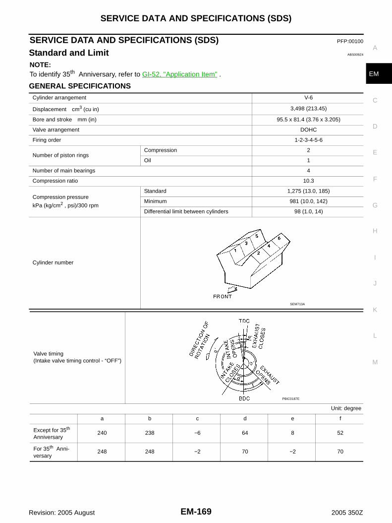
SERVICE DATA AND SPECIFICATIONS (SDS)
EM-169
C
D
E
F
G
H
I
J
K
L
M
A
EM
Revision: 2005 August 2005 350Z
SERVICE DATA AND SPECIFICATIONS (SDS) PFP:00100
Standard and Limit ABS009Z4
NOTE:To identify 35th Anniversary, refer to GI-52, "Application Item" .
GENERAL SPECIFICATIONSCylinder arrangement V-6
Displacement cm3 (cu in) 3,498 (213.45)
Bore and stroke mm (in) 95.5 x 81.4 (3.76 x 3.205)
Valve arrangement DOHC
Firing order 1-2-3-4-5-6
Number of piston ringsCompression 2
Oil 1
Number of main bearings 4
Compression ratio 10.3
Compression pressure
kPa (kg/cm2 , psi)/300 rpm
Standard 1,275 (13.0, 185)
Minimum 981 (10.0, 142)
Differential limit between cylinders 98 (1.0, 14)
Cylinder number
SEM713A
Valve timing(Intake valve timing control - “OFF”)
Unit: degree
a b c d e f
Except for 35th Anniversary
240 238 −6 64 8 52
For 35th Anni-versary
248 248 −2 70 −2 70
PBIC0187E

EM-170
SERVICE DATA AND SPECIFICATIONS (SDS)
Revision: 2005 August 2005 350Z
DRIVE BELT
*: If belt tension gauge cannot be installed at check points shown, check drive belt tension at different location on the belt.
INTAKE MANIFOLD COLLECTOR, INTAKE MANIFOLD AND EXHAUST MANIFOLDUnit: mm (in)
SPARK PLUG
Deflection adjustment Unit: mm (in) Tension adjustment* Unit: N (kg, lb)
Used beltNew belt
Used beltNew belt
Limit After adjustment Limit After adjustment
Alternator and power steering oil pump belt
7 (0.28)4 - 5
(0.16 - 0.20)3.5 - 4.5
(0.138 - 0.177)294 (30, 66)
730 - 818(74.5 - 83.5,164 - 184)
838 - 926(85.5 - 94.5,188 - 208)
A/C compressor belt
12 (0.47)9 - 10
(0.35 - 0.39)8 - 9
(0.31 - 0.35)196 (20, 44)
348 - 436(35.5 - 44.5,
78 - 98)
470 - 559(48 - 57,
106 - 126)
Applied pushing force
98 N (10 kg, 22 lb) —
KBIA1731J
Items Limit
Surface distortion
Intake manifold collector (upper) 0.1 (0.004)
Intake manifold collector (lower) 0.1 (0.004)
Intake manifold 0.1 (0.004)
Exhaust manifold 0.3 (0.012)
Make NGK
Standard type PLFR5A-11
Hot type PLFR4A-11
Cold type PLFR6A-11
Gap (nominal) 1.1 mm (0.043 in)
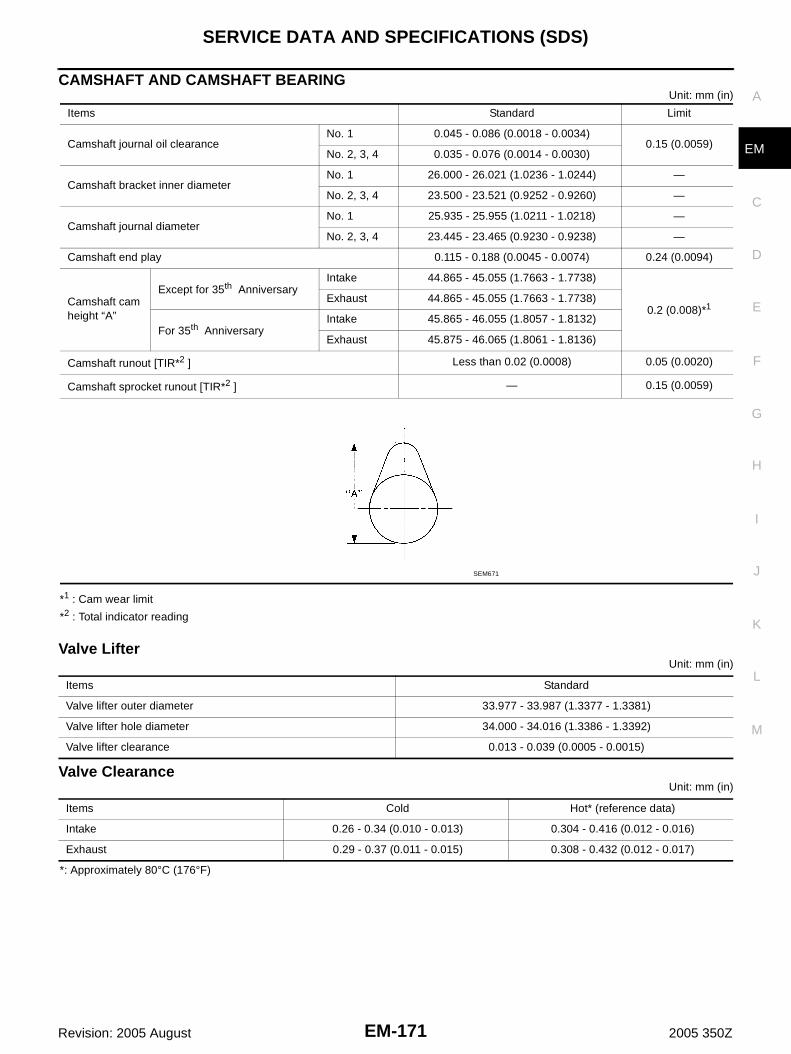
SERVICE DATA AND SPECIFICATIONS (SDS)
EM-171
C
D
E
F
G
H
I
J
K
L
M
A
EM
Revision: 2005 August 2005 350Z
CAMSHAFT AND CAMSHAFT BEARINGUnit: mm (in)
*1 : Cam wear limit
*2 : Total indicator reading
Valve LifterUnit: mm (in)
Valve ClearanceUnit: mm (in)
*: Approximately 80°C (176°F)
Items Standard Limit
Camshaft journal oil clearanceNo. 1 0.045 - 0.086 (0.0018 - 0.0034)
0.15 (0.0059)No. 2, 3, 4 0.035 - 0.076 (0.0014 - 0.0030)
Camshaft bracket inner diameterNo. 1 26.000 - 26.021 (1.0236 - 1.0244) —
No. 2, 3, 4 23.500 - 23.521 (0.9252 - 0.9260) —
Camshaft journal diameterNo. 1 25.935 - 25.955 (1.0211 - 1.0218) —
No. 2, 3, 4 23.445 - 23.465 (0.9230 - 0.9238) —
Camshaft end play 0.115 - 0.188 (0.0045 - 0.0074) 0.24 (0.0094)
Camshaft cam height “A”
Except for 35th AnniversaryIntake 44.865 - 45.055 (1.7663 - 1.7738)
0.2 (0.008)*1Exhaust 44.865 - 45.055 (1.7663 - 1.7738)
For 35th AnniversaryIntake 45.865 - 46.055 (1.8057 - 1.8132)
Exhaust 45.875 - 46.065 (1.8061 - 1.8136)
Camshaft runout [TIR*2 ] Less than 0.02 (0.0008) 0.05 (0.0020)
Camshaft sprocket runout [TIR*2 ] — 0.15 (0.0059)
SEM671
Items Standard
Valve lifter outer diameter 33.977 - 33.987 (1.3377 - 1.3381)
Valve lifter hole diameter 34.000 - 34.016 (1.3386 - 1.3392)
Valve lifter clearance 0.013 - 0.039 (0.0005 - 0.0015)
Items Cold Hot* (reference data)
Intake 0.26 - 0.34 (0.010 - 0.013) 0.304 - 0.416 (0.012 - 0.016)
Exhaust 0.29 - 0.37 (0.011 - 0.015) 0.308 - 0.432 (0.012 - 0.017)

EM-172
SERVICE DATA AND SPECIFICATIONS (SDS)
Revision: 2005 August 2005 350Z
Available Valve LifterUnit: mm (in)
Identification (stamped) mark Thickness
788U or 788R 7.88 (0.3102)
790U or 790R 7.90 (0.3110)
792U or 792R 7.92 (0.3118)
794U or 794R 7.94 (0.3126)
796U or 796R 7.96 (0.3134)
798U or 798R 7.98 (0.3142)
800U or 800R 8.00 (0.3150)
802U or 802R 8.02 (03.157)
804U or 804R 8.04 (0.3165)
806U or 806R 8.06 (0.3173)
808U or 808R 8.08 (0.3181)
810U or 810R 8.10 (0.3189)
812U or 812R 8.12 (0.3197)
814U or 814R 8.14 (0.3205)
816U or 816R 8.16 (0.3213)
818U or 818R 8.18 (0.3220)
820U or 820R 8.20 (0.3228)
822U or 822R 8.22 (0.3236)
824U or 824R 8.24 (0.3244)
826U or 826R 8.26 (0.3252)
828U or 828R 8.28 (0.3260)
830U or 830R 8.30 (0.3268)
832U or 832R 8.32 (0.3276)
834U or 834R 8.34 (0.3283)
836U or 836R 8.36 (0.3291)
838U or 838R 8.38 (0.3299)
840U or 840R 8.40 (0.3307)
SEM758G

SERVICE DATA AND SPECIFICATIONS (SDS)
EM-173
C
D
E
F
G
H
I
J
K
L
M
A
EM
Revision: 2005 August 2005 350Z
CYLINDER HEADUnit: mm (in)
Valve DimensionsUnit: mm (in)
Items Standard Limit
Head surface distortion Less than 0.03 (0.0012) 0.1 (0.004)
Normal cylinder head height “H” 126.3 - 126.5 (4.972 - 4.980) —
PBIC0924E
Valve head diameter “D” Intake 37.0 - 37.3 (1.4567 - 1.4685)
Exhaust 31.2 - 31.5 (1.228 - 1.240)
Valve length “L”Intake 96.37 (3.794)
Exhaust 93.99 (3.700)
Valve stem diameter “d”Intake 5.965 - 5.980 (0.2348 - 0.2354)
Exhaust 5.955 - 5.970 (0.2344 - 0.2350)
Valve seat angle “α”Intake
45°15′ - 45°45′Exhaust
Valve margin “T”Intake 1.1 (0.043)
Exhaust 1.3 (0.051)
Valve margin “T” limit 0.5 (0.020)
Valve stem end surface grinding limit 0.2 (0.008)
SEM188

EM-174
SERVICE DATA AND SPECIFICATIONS (SDS)
Revision: 2005 August 2005 350Z
Valve GuideUnit: mm (in)
Items Standard 0.2 (0.008) oversize (Service)
Valve guideOuter diameter 10.023 - 10.034 (0.3946 - 0.3950) 10.223 - 10.234 (0.4025 - 0.4029)
Inner diameter (Finished size) 6.000 - 6.018 (0.2362 - 0.2369)
Cylinder head valve guide hole diameter 9.975 - 9.996 (0.3927 - 0.3935) 10.175 - 10.196 (0.4006 - 0.4014)
Interference fit of valve guide 0.027 - 0.059 (0.0011 - 0.0023)
Items Standard Limit
Valve guide clearanceIntake 0.020 - 0.053 (0.0008 - 0.0021) 0.08 (0.003)
Exhaust 0.030 - 0.063 (0.0012 - 0.0025) 0.09 (0.004)
Projection length “L” 12.6 - 12.8 (0.496 - 0.504)
SEM950E

SERVICE DATA AND SPECIFICATIONS (SDS)
EM-175
C
D
E
F
G
H
I
J
K
L
M
A
EM
Revision: 2005 August 2005 350Z
Valve SeatUnit: mm (in)
Valve Spring
Items Standard Oversize [0.5 (0.020)] (Service)
Cylinder head seat recess diameter “D”Intake 38.000 - 38.016 (1.4961 - 1.4967) 38.500 - 38.516 (1.5157 - 1.5164)
Exhaust 32.200 - 32.216 (1.2677 - 1.2683) 32.700 - 32.716 (1.2874 - 1.2880)
Valve seat outer diameter “d”Intake 38.097 - 38.113 (1.4999 - 1.5005) 38.597 - 38.613 (1.5196 - 1.5202)
Exhaust 32.280 - 32.296 (1.2709 - 1.2715) 32.780 - 32.796 (1.2905 - 1.2912)
Valve seat interference fitIntake 0.081 - 0.113 (0.0032 - 0.0044)
Exhaust 0.064 - 0.096 (0.0025 - 0.0038)
Items Standard Service
Height “h”Intake 5.9 - 6.0 (0.232 - 0.236) 5.05 - 5.15 (0.1988 - 0.2028)
Exhaust 5.9 - 6.0 (0.232 - 0.236) 4.95 - 5.05 (0.1949 - 0.1988)
Depth “H” 6.0 (0.246)
PBIC2269E
Items Except for 35th Anniversary For 35th Anniversary
Free height 47.07 mm (1.8531 in) 45.43 mm (1.7886 in)
Installation height 37.00 mm (1.4567 in) 37.00 mm (1.4567 in)
Installation load 166 - 188 N (16.9 - 19.2 kg, 37 - 42 lb) 166 - 188 N (16.9 - 19.2 kg, 37 - 42 lb)
Height during valve open 27.2 mm (1.0709 in) 26.8 mm (1.0551 in)
Load with valve open 373 - 421 N (38.0 - 42.9 kg, 84 - 95 lb) 434 - 490 N (44.3 - 50.0 kg, 97.6 - 110.2 lb)
squareness 2.1 mm (0.083 in) 2.0 mm (0.079 in)

EM-176
SERVICE DATA AND SPECIFICATIONS (SDS)
Revision: 2005 August 2005 350Z
CYLINDER BLOCKUnit: mm (in)
Surface distortionStandard Less than 0.03 (0.0012)
Limit 0.1 (0.004)
Main bearing housing inner diameter Standard 63.993 - 64.017 (2.5194 - 2.5203)
Cylinder bore Inner diameterStandard
Grade No. 1 95.500 - 95.510 (3.7598 - 3.7602)
Grade No. 2 95.510 - 95.520 (3.7602 - 3.7606)
Grade No. 3 95.520 - 95.530 (3.7606 - 3.7610)
Wear limit 0.2 (0.008)
Out-of-round (Difference between “X” and “Y”)Limit
0.015 (0.0006)
Taper (Difference between “A” and “C”) 0.01 (0.0004)
Main bearing housing inner diameter (Without bearing)
Grade No. AGrade No. BGrade No. CGrade No. DGrade No. EGrade No. FGrade No. GGrade No. HGrade No. JGrade No. KGrade No. LGrade No. MGrade No. NGrade No. PGrade No. RGrade No. SGrade No. TGrade No. UGrade No. VGrade No. WGrade No. XGrade No. YGrade No. 4Grade No. 7
63.993 - 63.994 (2.5194 - 2.5194)63.994 - 63.995 (2.5194 - 2.5195)63.995 - 63.996 (2.5195 - 2.5195)63.996 - 63.997 (2.5195 - 2.5196)63.997 - 63.998 (2.5196 - 2.5196)63.998 - 63.999 (2.5196 - 2.5196)63.999 - 64.000 (2.5196 - 2.5197)64.000 - 64.001 (2.5197 - 2.5197)64.001 - 64.002 (2.5197 - 2.5198)64.002 - 64.003 (2.5198 - 2.5198)64.003 - 64.004 (2.5198 - 2.5198)64.004 - 64.005 (2.5198 - 2.5199)64.005 - 64.006 (2.5199 - 2.5199)64.006 - 64.007 (2.5199 - 2.5200)64.007 - 64.008 (2.5200 - 2.5200)64.008 - 64.009 (2.5200 - 2.5200)64.009 - 64.010 (2.5200 - 2.5201)64.010 - 64.011 (2.5201 - 2.5201)64.011 - 64.012 (2.5201 - 2.5202)64.012 - 64.013 (2.5202 - 2.5202)64.013 - 64.014 (2.5202 - 2.5202)64.014 - 64.015 (2.5202 - 2.5203)64.015 - 64.016 (2.5203 - 2.5203)64.016 - 64.017 (2.5203 - 2.5203)
Difference in inner diameter between cylinders Standard Less than 0.03 (0.0012)
PBIC0923E

SERVICE DATA AND SPECIFICATIONS (SDS)
EM-177
C
D
E
F
G
H
I
J
K
L
M
A
EM
Revision: 2005 August 2005 350Z
PISTON, PISTON RING AND PISTON PINAvailable Piston
Unit: mm (in)
Piston RingUnit: mm (in)
Piston PinUnit: mm (in)
Items Standard 0.20 (0.0079) oversize
“a” dimension 41.0 (1.614)
Piston skirt diameter “A”
Grade No. 1 95.480 - 95.490 (3.7590 - 3.7594) —
Grade No. 2 95.490 - 95.500 (3.7594 - 3.7598) —
Grade No. 3 95.500 - 95.510 (3.7598 - 3.7602) —
Service — 95.680 - 95.710 (3.7669 - 3.7681)
Items Standard Limit
Piston pin hole diameterGrade No. 0 21.993 - 21.999 (0.8659 - 0.8661) —
Grade No. 1 21.999 - 22.005 (0.8661 - 0.8663) —
Piston to cylinder bore clearance 0.010 - 0.030 (0.0004 - 0.0012) 0.08 (0.0031)
SEM882E
Items
Standard Limit
Except for 35th Anniversary
For 35th Anniver-sary
Except for 35th Anniversary
For 35th Anniver-sary
Side clearance
Top0.045 - 0.080
(0.0018 - 0.0031)0.11 (0.0043) 0.11 (0.0043)
2nd0.030 - 0.070
(0.0012 - 0.0028)0.10 (0.0039) 0.10 (0.0039)
Oil ring0.065 - 0.135
(0.0026 - 0.0053)— 0.17 (0.0067)
End gap
Top0.23 - 0.33
(0.0091 - 0.0130)0.23 - 0.33
(0.0091 - 0.0130)0.54 (0.0213) 0.54 (0.0213)
2nd0.33 - 0.48
(0.0130 - 0.0189)0.23 - 0.33
(0.0091 - 0.0130)0.80 (0.0315) 0.53 (0.0209)
Oil (rail ring)0.20 - 0.50
(0.0079 - 0.0197)0.20 - 0.50
(0.0079 - 0.0197)0.95 (0.0374) 0.85 (0.0335)
Items Standard Limit
Piston pin outer diameterGrade No. 0 21.989 - 21.995 (0.8657 - 0.8659) —
Grade No. 1 21.995 - 22.001 (0.8659 - 0.8662) —
Piston to piston pin oil clearance 0.002 - 0.006 (0.0001 - 0.0002) —
Connecting rod bushing oil clearance 0.005 - 0.017 (0.0002 - 0.0007) 0.030 (0.0012)

EM-178
SERVICE DATA AND SPECIFICATIONS (SDS)
Revision: 2005 August 2005 350Z
CONNECTING RODUnit: mm (in)
*: After installing in connecting rod
Items Standard Limit
Center distance 144.15 - 144.25 (5.6752 - 5.6791) —
Bend [per 100 (3.94)] — 0.15 (0.0059)
Torsion [per 100 (3.94)] — 0.30 (0.0118)
Connecting rod bushing inner diameter*Grade No. 0 22.000 - 22.006 (0.8661 - 0.8664) —
Grade No. 1 22.006 - 22.012 (0.8664 - 0.8666) —
Connecting rod big end diameter (Without bearing) 55.000 - 55.013 (2.1654 - 2.1659) —
Side clearance 0.20 - 0.35 (0.0079 - 0.0138) 0.40 (0.0157)

SERVICE DATA AND SPECIFICATIONS (SDS)
EM-179
C
D
E
F
G
H
I
J
K
L
M
A
EM
Revision: 2005 August 2005 350Z
CRANKSHAFTUnit: mm (in)
*: Total indicator reading
Main journal diameter. “Dm” Standard
Grade No. AGrade No. BGrade No. CGrade No. DGrade No. EGrade No. FGrade No. GGrade No. HGrade No. JGrade No. KGrade No. LGrade No. MGrade No. NGrade No. PGrade No. RGrade No. SGrade No. TGrade No. UGrade No. VGrade No. WGrade No. XGrade No. YGrade No. 4Grade No. 7
59.974 - 59.975 (2.3612 - 2.3612)59.973 - 59.974 (2.3611 - 2.3612)59.972 - 59.973 (2.3611 - 2.3611)59.971 - 59.972 (2.3611 - 2.3611)59.970 - 59.971 (2.3610 - 2.3611)59.969 - 59.970 (2.3610 - 2.3610)59.968 - 59.969 (2.3609 - 2.3610)59.967 - 59.968 (2.3609 - 2.3609)59.966 - 59.967 (2.3609 - 2.3609)59.965 - 59.966 (2.3608 - 2.3609)59.964 - 59.965 (2.3608 - 2.3608)59.963 - 59.964 (2.3607 - 2.3608)59.962 - 59.963 (2.3607 - 2.3607)59.961 - 59.962 (2.3607 - 2.3607)59.960 - 59.961 (2.3606 - 2.3607)59.959 - 59.960 (2.3606 - 2.3606)59.958 - 59.959 (2.3605 - 2.3606)59.957 - 59.958 (2.3605 - 2.3605)59.956 - 59.957 (2.3605 - 2.3605)59.955 - 59.956 (2.3604 - 2.3605)59.954 - 59.955 (2.3604 - 2.3604)59.953 - 59.954 (2.3603 - 2.3604)59.952 - 59.953 (2.3603 - 2.3603)59.951 - 59.952 (2.3603 - 2.3603)
Pin journal diameter. “Dp” Standard
Grade No. 0 51.968 - 51.974 (2.0460 - 2.0462)
Grade No. 1 51.962 - 51.968 (2.0457 - 2.0460)
Grade No. 2 51.956 - 51.962 (2.0455 - 2.0457)
Center distance “r” 40.66 - 40.74 (1.6008 - 1.6039)
Out-of-round (Difference between “X” and “Y”)Limit
0.002 (0.0001)
Taper (Difference between “A” and “B”) 0.002 (0.0001)
Crankshaft runout [TIR*]Standard Less than 0.05 (0.0020)
Limit 0.10 (0.0039)
Crankshaft end playStandard 0.10 - 0.25 (0.0039 - 0.0098)
Limit 0.30 (0.0118)
SEM645 SBIA0535E
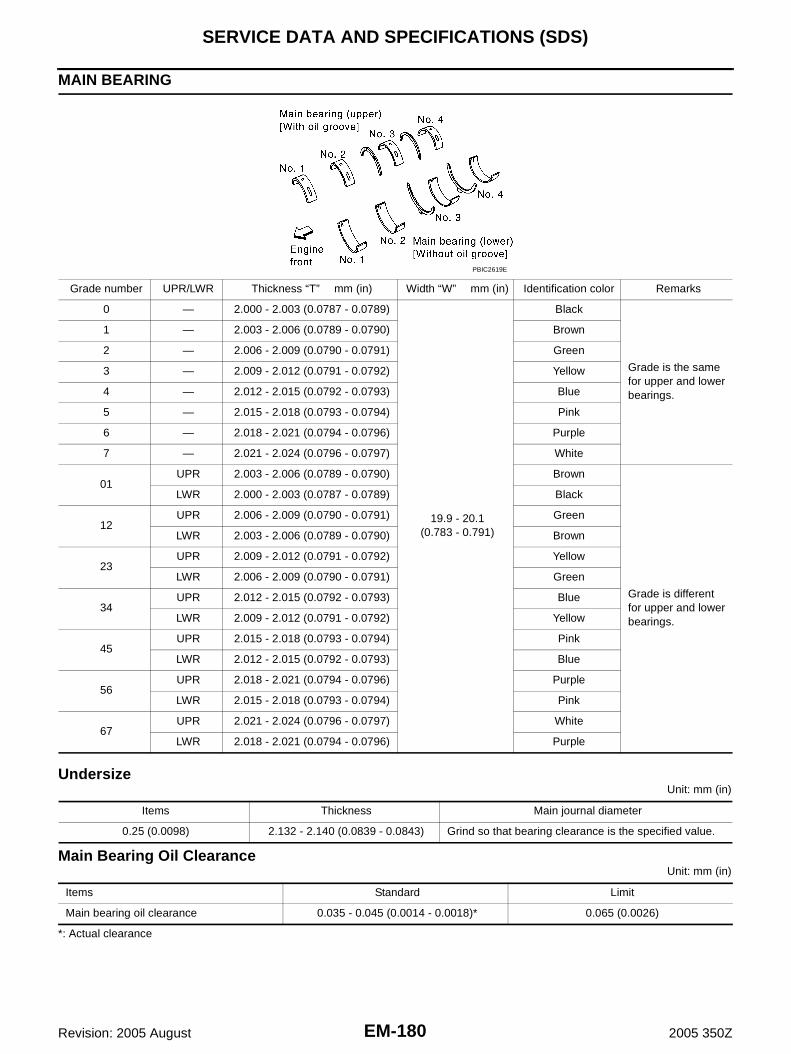
EM-180
SERVICE DATA AND SPECIFICATIONS (SDS)
Revision: 2005 August 2005 350Z
MAIN BEARING
UndersizeUnit: mm (in)
Main Bearing Oil ClearanceUnit: mm (in)
*: Actual clearance
Grade number UPR/LWR Thickness “T” mm (in) Width “W” mm (in) Identification color Remarks
0 — 2.000 - 2.003 (0.0787 - 0.0789)
19.9 - 20.1(0.783 - 0.791)
Black
Grade is the same for upper and lower bearings.
1 — 2.003 - 2.006 (0.0789 - 0.0790) Brown
2 — 2.006 - 2.009 (0.0790 - 0.0791) Green
3 — 2.009 - 2.012 (0.0791 - 0.0792) Yellow
4 — 2.012 - 2.015 (0.0792 - 0.0793) Blue
5 — 2.015 - 2.018 (0.0793 - 0.0794) Pink
6 — 2.018 - 2.021 (0.0794 - 0.0796) Purple
7 — 2.021 - 2.024 (0.0796 - 0.0797) White
01UPR 2.003 - 2.006 (0.0789 - 0.0790) Brown
Grade is different for upper and lower bearings.
LWR 2.000 - 2.003 (0.0787 - 0.0789) Black
12UPR 2.006 - 2.009 (0.0790 - 0.0791) Green
LWR 2.003 - 2.006 (0.0789 - 0.0790) Brown
23UPR 2.009 - 2.012 (0.0791 - 0.0792) Yellow
LWR 2.006 - 2.009 (0.0790 - 0.0791) Green
34UPR 2.012 - 2.015 (0.0792 - 0.0793) Blue
LWR 2.009 - 2.012 (0.0791 - 0.0792) Yellow
45UPR 2.015 - 2.018 (0.0793 - 0.0794) Pink
LWR 2.012 - 2.015 (0.0792 - 0.0793) Blue
56UPR 2.018 - 2.021 (0.0794 - 0.0796) Purple
LWR 2.015 - 2.018 (0.0793 - 0.0794) Pink
67UPR 2.021 - 2.024 (0.0796 - 0.0797) White
LWR 2.018 - 2.021 (0.0794 - 0.0796) Purple
PBIC2619E
Items Thickness Main journal diameter
0.25 (0.0098) 2.132 - 2.140 (0.0839 - 0.0843) Grind so that bearing clearance is the specified value.
Items Standard Limit
Main bearing oil clearance 0.035 - 0.045 (0.0014 - 0.0018)* 0.065 (0.0026)

SERVICE DATA AND SPECIFICATIONS (SDS)
EM-181
C
D
E
F
G
H
I
J
K
L
M
A
EM
Revision: 2005 August 2005 350Z
CONNECTING ROD BEARING
UndersizeUnit: mm (in)
Connecting Rod Bearing Oil ClearanceUnit: mm (in)
*: Actual clearance
Tightening Torque ABS009Z5
NOTE:To identify 35th Anniversary, refer to GI-52, "Application Item" .*1: Parts to be tightened in particular orders.1)-: Order of tightening when tightening two or more times separately. Unit: N·m (kg-m, ft-lb) Unit: N·m (kg-m, in-lb)*2
Grade number Thickness “T” mm (in) Identification color (mark)
0 1.500 - 1.503 (0.0591 - 0.0592) Black
1 1.503 - 1.506 (0.0592 - 0.0593) Brown
2 1.506 - 1.509 (0.0593 - 0.0594) Green
Items Thickness Crank pin journal diameter
0.25 (0.0098) 1.626 - 1.634 (0.0640 - 0.0643) Grind so that bearing clearance is the specified value.
Items Standard Limit
Connecting rod bearing oil clearance 0.034 - 0.059 (0.0013 - 0.0023)* 0.070 (0.0028)
Air cleaner and air duct 5.5 (0.56, 49)*2
Mass air flow sensor 5.5 (0.56, 49)*2
Engine cover 5.0 - 6.5 (0.51 - 0.66, 45 - 57)*2
*1 Intake manifold collector (upper) 11.8 - 13.7 (1.2 - 1.3, 9 - 10)
*1 Intake manifold collector (lower) 11.8 - 13.7 (1.2 - 1.3, 9 - 10)
*1 Electric throttle control actuator 7.2 - 9.7 (0.74 - 0.98, 64 - 85)*2
EVAP canister purge volume control solenoid valve 5.9 - 8.0 (0.61 - 0.81, 53 - 70)*2
*1 Intake manifold 1) 4.9 - 9.8 (0.5 - 1.0, 4 - 7)
2) 26.5 - 31.4 (2.7 - 3.2, 20 - 23)
Exhaust manifold cover 5.8 (0.59, 51)*2
Exhaust manifold stud 14.7 (1.5, 11)
*1 Exhaust manifold 30.5 (3.1, 22)
Tree way catalyst 63.0 (6.4, 46)
Air fuel ratio sensor 1 50.0 (5.1, 37)
Heated oxygen sensor 2 45.0 (4.6, 33)
*1 Oil pan (lower) 7.0 (0.71, 62)*2
*1 Oil pan (upper) 17.2 (1.8, 13)
Oil strainer 21.6 (2.2, 16)
Oil pan drain plug 34.3 (3.5, 25)
Rear plate cover 7.0 (0.71, 62)*2
Crankshaft position sensor (POS) 9.6 (0.98, 85)*2
Ignition coil 9.0 (0.92, 80)*2
Spark plug 24.5 (2.5, 18)

EM-182
SERVICE DATA AND SPECIFICATIONS (SDS)
Revision: 2005 August 2005 350Z
Fuel hose clamp bracket (right member side) 5.0 (0.51, 44)*2
Fuel feed hose (with damper) 8.4 (0.86, 74)*2
Fuel sub-tube 9.6 (0.98, 85)*2
Fuel damper 9.6 (0.98, 85)*2
*1 Fuel tube 1) 9.3 - 10.8 (0.95 - 1.1, 6.9 - 7.9)
2) 20.6 - 26.5 (2.1 - 2.7, 16 - 19)
*1 Rocker cover 1) 0.96 - 2.96 (0.10 - 0.30, 9 - 26)*2
2) 7.33 - 9.33 (0.75 - 0.95, 65 - 82)*2
PCV valve 2.5 (0.26, 22)*2
*1 Intake valve timing control cover (Except for 35th Anniversary) 11.3 (1.2, 8)
*1 Valve timing control cover (For 35th Anniversary) 11.3 (1.2, 8)
Camshaft sprocket (INT) 103 (11, 76)
Camshaft sprocket (EXH) (Except for 35th Anniversary) 123 (13, 91)
Camshaft sprocket (EXH) (For 35th Anniversary) 103 (11, 76)
Timing chain tensioner (primary) 8.1 (0.83, 72)*2
Timing chain tensioner (secondary) 8.5 (0.87, 75)*2
Internal chain guide 8.1 (0.83, 72)*2
Tension guide 21.6 (2.2, 16)
Slack guide 15.7 (1.6, 12)
Crankshaft pulley 1) 39.2 - 49.0 (4.0 - 5.0, 29 - 36)
2) 84° - 90° (angle tightening)
Chain tensioner cover 11.3 (1.2, 8)
Water pump cover 11.3 (1.2, 8)
Water hose clamp mounting bolt (Only models except for 35th Anniversary) 74.0 (7.5, 55)
*1 Front timing chain case M6 bolt 12.7 (1.3, 9)
M8 bolt 28.4 (2.9, 21)
*1 Rear timing chain case 12.7 (1.3, 9)
*1 Camshaft bracket 1) 1.96 (0.2, 17)*2
2) 1.96 (0.2, 17)*2
3) 5.88 (0.6, 52)*2
4) 9.02 - 11.8 (0.92 - 1.20, 80 - 104)*2
5) 8.3 - 10.3 (0.85 - 1.0, 74 - 91)*2
Camshaft position sensor (PHASE) 9.6 (0.98, 85)*2
Exhaust valve timing control position sensor (Only for 35th Anniversary) 9.6 (0.98, 85)*2
Intake valve timing control solenoid valve 11.3 (1.2, 8)
*1 Cylinder head 1) 98.1 (10, 72)
2) 0 (0, 0)
3) 34.3 - 44.1 (3.5 - 4.4, 26 - 32)
4) 90° - 95° (angle tightening)
5) 90° - 95° (angle tightening)
*1 Engine mounting bracket (RH and LH) 49.0 (5.0, 36)
Engine mounting insulator (RH and LH) 92.5 (9.4, 68)

SERVICE DATA AND SPECIFICATIONS (SDS)
EM-183
C
D
E
F
G
H
I
J
K
L
M
A
EM
Revision: 2005 August 2005 350Z
*1 Rear engine mounting member 49.0 (5.0, 36)
Engine mounting insulator (rear) 49.0 (5.0, 36)
Mass damper 49.0 (5.0, 36)
Dynamic damper [M/T models (For Coupe)] 49.0 (5.0, 36)
*1 Main bearing cap 1) 32.3 - 38.3 (3.3 - 3.9, 24 - 28)
2) 90° - 95° (angle tightening)
Connecting rod 1) 18.6 - 20.6 (1.9 - 2.1, 14 - 15)
2) 90° - 95° (angle tightening)
Oil jet 27.0 (2.8, 20)
Knock sensor 23.6 (2.4, 1.7)
Flywheel (M/T models) 88.2 (9.0, 65)
Drive plate (A/T models) 88.2 (9.0, 65)
Rear oil seal retainer 8.8 (0.9, 78)*2

EM-184
SERVICE DATA AND SPECIFICATIONS (SDS)
Revision: 2005 August 2005 350Z