Embed Size (px)
Citation preview
AFAPUTR.75.1 00 & ./•2)VOLUME II •
CC)
ENGINE SYSTEMS OWNERSHIP COST REDUCTION INAIRCRAFT PROPULSION SUBSYSTEM INTEGRATION
C• (APSI)
"•' TEL ED YNE CAE
1330 LASKEY ROADTOLEDO, OH.'O 43612
(i
AUGUST 1975
INTERIM REPORT FOR PERIOD APRIL 1973 - AUGUST 1975 '
SApproved ror public release: distribution unlim~ited1
AIR FORCE AERO-PROPULSION LABORATORYAIR FORCE WRIGHT AERONAUTICAL LABORATORIESAIR FORCE SYSTEMS COMMANDWRIGHT-PATTERSON AIR FORCE BASE, OHIO 45433
NOTICE..'
When Government drawings, specifications, or other data are used for any purposeother than in connection with a definitely related Government procurement operation,the United States Government thereby incurs no responsibility nor any obligationwhat soever; and the fact that the Government may have formulated, furnished, or inany way supplied the said drawings, specifications, or other data, is not to beregarded by implication or otherwise as in any manner licensing the holder or anyother person or corporation, or conveying any rights or permission to manufacture,use, or sell any-,patented invention that may in any way be related thereto.
This Inter Final Report was submitted by Teledyne CAE, under Contract F33657-73-C-620. The ef l as sponsored by the Air Force Aero Propulsion Laboratory, AirForce Systems Command, Wright Patterson AFB, Ohio, under Project 668A, Task 01,and Work Unit 05 with Thomas J. Gingrich as Project Engineer. Mr. Wesley Knightof Teledyne CAE was technically responsible. This report was authored and editedby Messrs. William Wagner and Alfred Gabrys.
This report has been reviewed by the Information Office, (ASD/OIP) and is releasableto the National Technical Information Service (NTIS). At NTIS, it will be availableto the General Public, including Foreign Nations.
This technical report has been reviewed and is approved for publication.
THOMAS J. GfNGRICHPROJECT ENGINEERFOR THE COMMANDER '•-•--
SYSTEM ENGINE TECHNOLOGY
A 4 - V -
UnclassifiedSECURITY CLASSIFICATION OF THIS PAGE (When Date Enter~ed)
READ INSTRUCTIONS.'-j5REPORT DOCUMENTATION PAGE BEFORE COMPLETING FORM1. 2. GOVT ACCESSION NO. 3. RECIPIENT'S CATALOG NUMBER
* /AFAPIj'frR-7 -loo-Vol-II-/-4. TiTLE,(.d .bIIIff. 5 TP F PIT5PRO ot_7'.
/1 E ngine Systems Ownership Cost Reduction -f 17~Aircraft Propulsion Subsystems IntegrationApti'7-Auuif7
- . W. Wagner, A. Gabrys, W.,Knight 3677rO2
5. PERFORMING ORAIAIONAME AND ADDRESS _.0P.R1GRA. ELF.ENT.PRQJECJ.T. TASK.'/A~_- a UNIT NUMB3ERS:
Teledyne CAE L/'Toledo, Ohio63202F-668A 01 I <'
11, CONTROILLING OFFICE NAME AND ADDRESS L2PORTOATE--
Air Th"rce Aero Propulsion Laboratory jAugu_`s:--975 ____
AFSC.-United States Air Force 13. NUMBER OF PAGF,.S. - ý
Wrip'-st-Patterson Air Force Base, Ohio 144 '-1IY x.14. MONITORING AGENCY NAME 6 'ý'RESS(If ,f,fferent from,, Conttofling Office) IS. SECURITY CLASS7ýol rXIrp rf- -
Urnclassif iedS-fa-. OECLASSIF;ICATIONý'CI)W,,'rOPAE;NG
SCH-EDULE
16. DIST~kIBUTION STATEMENT (.1 thi. R.,,rt)
Interim Report for period April 1973 - August 1975; approved for Publicrelease; distribution unlimited
17. DISTRIBUTION STATEMENT (of the *bstrart entfered in Block 20. if ditfci'ent from, Report)
18. SUPPLEMENTARY NOTES
19. KEY WORDS (Continue. on rev'erse side if necessary and identify by block nwmborI
Aircraft Propulsion Systems Design to CostCost Reduction LwCsCost-of Ownership LwCs
Gas Turbine Engine
20. ABSTRACT (CoIntinue on, revrsre side If necessary and identify by block number)
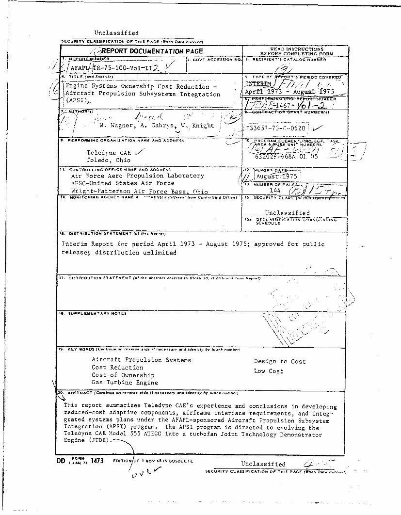
This report summarizes Teledyne CAE's experience and conclusions in developingreduced-cost adaptive components, airframe interface requirements, and integ-grated systems plans under the AFAPL-sponsored Aircraft Propulsion SubsystemIntegration (APSI) program. The APSI program is directed to evolving theTeledlyne CAE Model 555 ATEGG into a turbofan Joint Technology DemonstratorEngine (JTDE).
DD I JAN, 1473 EDITION>OF I NOV 6S IS OBSOLETE Unclassified !ý
v k VSECURITY CLASSIFICATION OF THIS PAGE (Who.n Data Fntered)
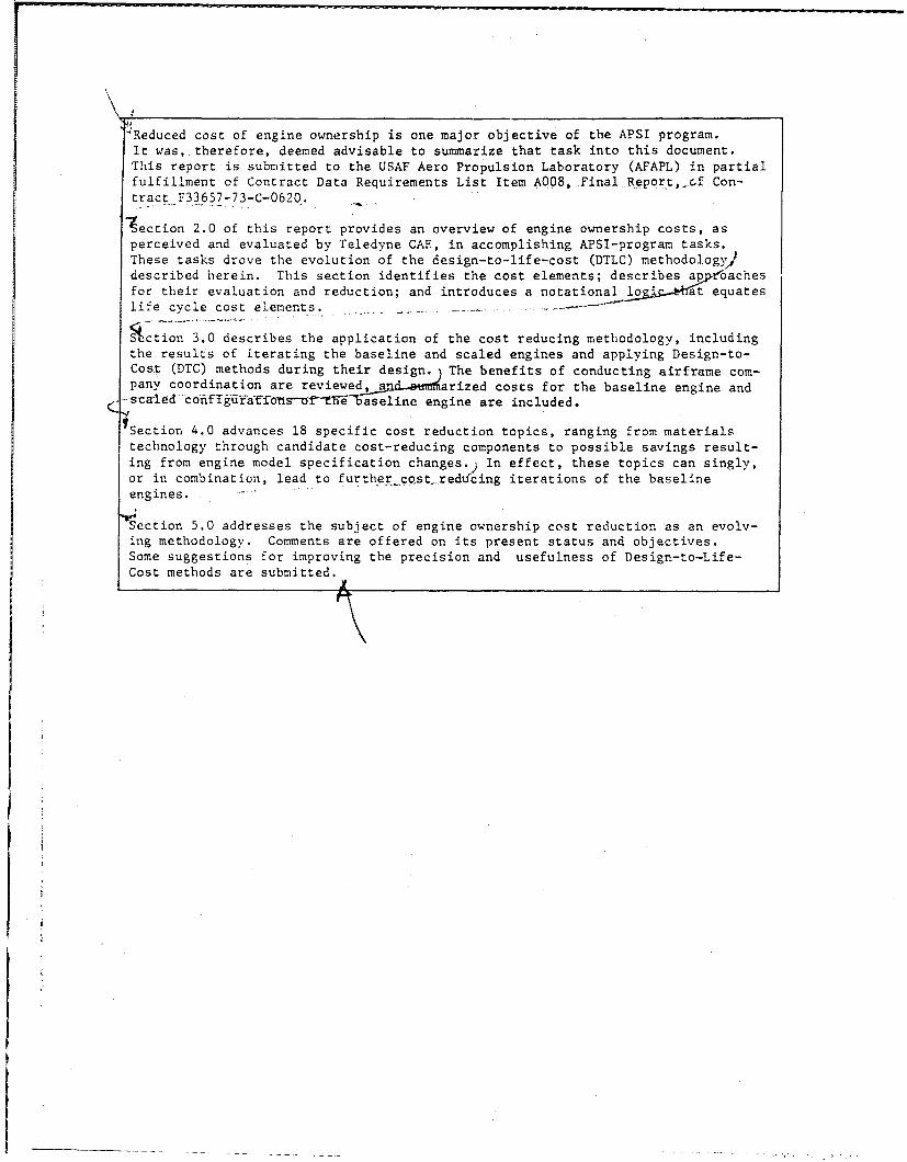
Reduced cost of engine ownership is one major objective of the APSI program.It was, therefore, deemed advisable to summarize that task into this document.This report is submitted to the USAF Aero Propulsion Laboratory (AFAPL) in partialfulfillment of Contract Data Requirements List Item A008, Final Report,xCf Con-tract F33657-73-C-0620.
'ection 2.0 of this report provides an overview of engine ownership costs, as
perceived and evaluated by Teledyne CAE, in accomplishing APSI-program tasks.These tasks drove the evolution of the design-to-life-cost (DTLC) methodology,$described herein. This section identifies the cost elements; describes ap•r•oachesfor their evaluation and reduction; and introduces a notational loat equateslife cycle cost elements.
Scction 3.0 describes the application of the cost reducing methodology, includingthe results of iterating the baseline and scaled engines and applying Design-to-Cost (DTC) methods during their design. The benefits of conducting airframe com-pany coordination are reviewed, a arized costs for the baseline engine and
s e 1eo un--aseline engine are included.
Section 4.0 advances 18 specific cost reduction topics, ranging from materialstechnology through candidate cost-reducing components to possible savings result-ing from engine model specification changes.) In effect, these topics can singly,or in combination, lead to furtherco.st. reducing iterations of the baselineengines.
Section 5.0 addresses the subject of engine ownership cost reduction as an evolv-ing methodology. Comments are offered on its present status and objectives.Some suggestions for improving the precision and usefulness of Design-to-Life-Cost methods are submitted.
Teledyne CAEReport No. 1467
FOREWORD
This report constitutes an advanced segment of the Final Technical Reportof the Aircraft Propulsion Subsystem Ii.tegration Contract, performed by Teledyne1CAE under the sponsorship of the United States Air Foice/Aero PropulsionLaboratory, Wright Patterson Air Force Base, Dayton, Ohio. The work describedherein was accomplished under Contract No. F33657-73-C-0620 with Mr. Robert
- Panella, AFAPL Project Engineer.
The work was performed by the technical staff of Teledyne CAE under thedirection of Mr. U'esley Knight, Project Engineer. This report was authored andedited by Meszirs. Alfred Gabrys and William Wagner of Teledyne CAE. It specifi-cally addresses the system cost reduction aspect of aircraft engine desihn andtechnology.
I -ML
- liii
Teledyne CAEReport No. 146'
TABLE OF CONTENTS
Section 1.0 -- Introduction 1
3. J. Purpose 11.2 Discuwsion of Contents 1
Section 2.0 - Propulsion Systems - Cost of Ownership 3
2.1 Mission Analysis 32.2 Elements of Systems Crst 4
Section 3.0 - APSI Cost Reduction 23
3.1 BacKground 23. 3.2 Baseline Engines 25
3.3 Scaled Engine Costs 253.4 System Cost Reduction 29
SSection 4.0 - Ccst Reduction Analyses 39
4.1 Aerodynamic Tradeoffs 394.2 Cost Reduction Topics 62
Section 5.0 - Technology Assessmert 135
5.1 Methodology; Status and Objectives 1355.2 Technical Risk 1395.3 Technical Risk Estimates for Adaptive Compo-
nents 139
References 143
i-
I __ i III
Teledyne CAEReport No. 1467
LIST OF ILLUSTRATIONS
Figure Title P
2.2-1 Engine Model Iteration 5
2.2-2 Cost Element Indenture/Duration: Typical EngineDevelopment Phase 7
2.2-3 Cost Element Indenture/Duzation: Typical Service
Phase 82.2.2-1 Engine Influence on Airframe Cost 122.2.3-1 Design-to-Cost Approach 132.2.3-2 Typical Material Pricing Curve for N-155 Sheet 162.2.3-3 Typical Machining Index for Single Point Turning 182.2.3-4 Hydrotel Airfoil Milling 19
3.1-1 Derivative Engine Applications. 243.2-1 Sample: Cost Group Summary Sheet 263.2-2 Sample: Detail Part Cost Worksheet 273.2-3 Sample: Engine Model Cost Estimate 28
3.4.2 Aircraft PLrameters Affecting APSI Cost 313.4.3-1 UPT Composite Miqsion Profile (Engine Operating Hours) 323.4.4 Postulated RPV Cumulative and Annual Engine Operating
Hours (Life Cycle) 343.4.-I At'5l-[erivatlve Engines Compared with Closest Available
Current Technology for UPT and MIIRPV Missions 363.4.5-2 Parameter Values for Estimating Derivative Engine Sys-
tem Cost Savings 37
4.1.1-1 Effect of Tip Clearance on Axial Compressor Efficiency 42 1
4.1.1-2 NASA Three-Stage Research Compressor 464.1.1-3 Stage Efficiency as a Function of Annulus Reynolds
Number, Rotor Tip Clearance/Blade Span and Aspect
Ratio 484.1.1-4 Comparison of Overall Performance Characteristics of
Narrow-Chord and Wide-Chord Rotors at Design TipSpeed 49
4,1.1-5 Effect of Leading Edge (Radius/Chord at Rotor Tip onRotor Performance) 51
4.1.1-6 Centrifugal Compressor Clearance Control 524.1.1-7 Effect of Impeller Tip Clearance/impeller Tip Passage
Width on Flow and Pressure Ratio 53
4.1.1-8 Typical Centrifugal Compressor As-Designed Inducer/
Nominal Diffuser 544.1.2-1 Effect of Number of Vanes and Blades on Stage Effi-
ciency 56
4.1.2-2 Effect of Rotor Tip Clearance on Stage Efficiency 561.1.2-3 Effect of Nozzle Trailing Edge Thickness on Stage
Efficiency 57
4.1.2-4 Effect of Rotor Trailing Edge Thickness on Stage Effi-ciency 58
vi
Teledyne CAE* xReport No. 1467
LIST OF ILLUSTRATIONS (continued)
T itle
4.1.2-5 Effect of Stage Efficiency by Varying Nozzle AspectRatio by Chord n- While Maintaining Constant Solidityand Maintaining Similar Blade Surface Velocity Distri-bution 59
4.1.2-6 Effect of Stage Efficiency by Varying Rotor AspectRatio by Chord n- While Maintaining Constant Solidity-and Maintaining Similar Blade Surface Velocity Distri-bution 59
4.1.2-) Vffect on Efficiency by Varying Nozzle Aspect Ratioby Vane Height 60
4.1.2--8 Ei'ffect on Efficiency by Varying Rotor Aspect Ratio bybiade Height 60
4.1.2-9 Combined Effects of Hardware Changes on Efficiency ofI.P Turbine 61_
4.2.1-1 Titanium Fan blade Cost Analysis Summary 66"4.2.1-2 fan Rotor Weight Versus Aspect Ratio - Titanium Blades
and Hub 674.2.1-3 Fan Rotor Cost Versus Aspect Ratio - Titanium Blades
Sand Hub 684.2.1-4 Fan Rotor Cost Versus Blade Aspect Ratio - Baseline
Thrust Engine, Ti Blades/Ti Hub 69L 4.2.1-5 Fan Rotor Cost Versus Blade Aspect Ratio - Half-1 Thrust Engine, Ti Blades/Ti Hub 70
4.2.1-6 Fan Rotor Cost Versus Blade Aspect Ratio - Twice-Thrust Engine, Ti Blades/Ti Hub 71
4.2.2-1 Forged Steel Fan Blade Cost Analysis Summary 744.2.2-2 Fan Rotor Weight Versus Aspect Ratio - Steel BladesA and Titanium Hub 754.2.2-3 Fan Rotor Cost Versus Aspect Ratio - Steel Blades and
Titanium Hub 764.2.3-1 Tensile Properties Comparison of Cast and Wrought
Titanium (6AL-4V) 784.2.3-2 Investment Cast Titanium Axial Compressor Rotor 79
4.2.3-3 Investment Cast Titanium Compressor Blades 804.2.4-1 Be/Ti Low Pressure Shaft - Natural Frequencies Versus
Support Spring Rates at 22,000 rpm 824.2.4-2 Schematic Presentation of Shaft Composition 834.2.4-3 Canning Process for Required Material Composition 834.2.4-4 Be/Ti Configuration and Composition 844.2.4-5 Be/Ti Price Projections Data (furnished by Brush
Wellman) 854.2.5-1 Preliminary Design Layout of Three-Stage Axial Rotor 874.2.5-2 Rotor Blade 874.2.5-3 Stress Summary - Brazed First Stage Blade on Ring
Disc 88
vii
Teledyne CAEReport No. 1467
LIST OF ILLUSTRATIONS (continued)
Figure Title PaE
4.2.7-1 Effect of Tolerance Band on Liner Temperature 924.2.7-2 Cost Comparison - Infusion Cooled Vaporizer Plate
Combustor Versus Baseline Engine Configuration 924.2.8-1 .trength Comparison of Ceramics (Si3 N4 ) and Super-
alloys 944.2.9-1 Preliminary Mechanical Properties Comparison - INCO
792 Versus IN-100 964.2.9-2 Sintered and Hot-Isostatic-Pressed Powdered Metal
Turbine Blade Made From INCO 792 (Radiographic Film) 974.2.9-3 Powder Metal Disc Outline (Dashed) 984.2.9-4 Tensile Properties of Forged Waspalloy and Powder
Metal Rene' 95 98
4.2.10-1 Comparison of Gas Flowpath for Co-Rotating VersusCounter-Rotating Engine HP and LP Shafts 1004.2.10-2 Cort Reduction of LP Turbine Inlet Nozzle Through
the Use of Counter-Rotating Shafts 1014.2.11-1 Welded LP Turbine Assembly 1034.2.12-1 Typical Cooled Turbine Blade Schematic Illustrating
Jet Flap Airflow 1054.2.12-2 Typical Cooled Turbine Blade Illustrating Jet Flap
Aerodynamic Effects 1054.2.12-3 Jet Flap Effects on High-Work Turbine 1064.2.13-1 Preliminary Design of Oil-Dammed Gas Seal 1084.2.14-1 Gas Foil Bearings 1104.2.14-2 Summary of Journal Bearing Loads for HP Shaft of Base-
line Engine 1134.2.15-1 Typical Teledyne CAE Expendable Oil Mist Rear Bearing
Lube System 115S4.2.15-2 Typical Teledyne CAE Front Bearing Wet Oil Sump Lube
System 115j 4.2.15-.3 Typical Oil Wick Lubrication System 116
4.2.15-4 Typical Teledyne CAF High-Speed Rotating Pump Element 11834.2,15-S Lubrication Systems Cost and Weight Summary 119
- 4.2.16 Relative Cost and Relative Weight Versus Thrust 1204.2.17-1 Ba5eline Engine Control System Requirements Compared
to Jl0O Control System 1224.2.17-2 Typical Swash Plate Fuel Pump Offers Promise as a
Central Element in a Simple, Low-Cost Control Scheme 1254.2.17-3 Bendix Fluidic Actuator 1254.2.18-1 Comparison of Specification Requirements/455 Applica-
uion 1284.2.18-2 Specification Cost Impact 1294.2.19-1 Cost Reduction Analysis Summary 133
viii

Teledyne CAEReport No. 1.467
LIST OF ILLUSTRATIONS (continued)
Figure Title Pg
5.1-1 Engine DTLC Model - Logic Flow 1375.2-1 LCC Reduction as a Function of Development Program
Success Probability 140
LIST OF TABLES
Table Title Pal•
4.1.1-1 Performance Degradation Example 40
I'II.
A
ix
!--.
.17
1$
- 1" . ... . ..... .. . ... - - .- Z .II.I
)
I1 -.

Fs PYLSCEDItG NCN FiU4ENO
Teladyn- CAE
Report No. 1467
SECTION 1.0 - INTRODUCTION
i.i Purpose
This report summarizes Teledyne CAE's experience and conclusions indeveloping reduced-cost adaptive components, airframe interface require-ments, and integrated systems plans under tbe AEAPL-sponsored AircraftPropulsion Subsystem Integration (APSI) program.
Reduced cost of engine ownership 1s one major objective of the APSIprogram. It was, therefore, deemed advisable to summarize thaL taskinto this document. This report is submitted to the USAF Aero Propul-sion Laboratory (AFAPL) in partial fulfillment of Contract Data Require-Ments List Item AO08, Final Report, of Contract F33657-73-C-0620.
1.2 Discussion of Contents
• • Section 2.0 of this report provides an overview of engine ownership
costs, as perceived and evaluated by Teledyne CAE, In accomplishingAFSI-program tasks. These tasks drove the evolution of the design-to-ife-cost (DTLC) methodology, described herein. This section identifies thecost elements; describes approaches for their evaluation and reduction;and introduces a notational logic that equates life cycle cost elements.
Section 3.0 describes the application of the cost redjcing methodology,including the results of iterating the baseline and scaled engines and"applying Design-to-Cost (DTC) methods during their design. The benefitsof conducting airframe company coordination are re-'ewed, and summarizedcosts for the baseline engine and scaled configurationq nf the baselineengine are included.
Section 4.0 advances eighteen specific cost reduction topics, rangingfrom materials technology through candidate cost-reducing componentsto possible savings resulting from engine model specification changes.In effect, these topics can singly, or in combination, lead to further
K cost reducing iterations of the baseline engines.
Section 5.0 addresses the subjeýct of engine ownership cost reduction as
an evolving methodology. Comments are offered or its present status andobjectives. Some suggestions for improving the precision and usefulness
of Design-to-Life-Cost methods are submitted.

it
Section 2.0
Propulsion Systems -Cost Of Ownership
Teledyne CAEReport No. 1.467
1 SECTION 2.0 - PROPULSION SYSTEMS - COST OF OWNERSHIP
2.1 Mission Analysis
The APSi program Statement of Work (SOW), clearly defined the objectiveof reducing the cost of engine ownership. During Phase I, (DesignDefinition) task emphasis included assessment of:
"...the effects of the Interrelationships between engine coapo-nent cost and performance factors on overall aircraft system
cost/engine component cost..."
The SOW also recognizes the need for a detailed mission scenario as a pre-requisite for evaluating tradeoffs, and goes on to require that:
"The contractor shall analyze USAF requirements,.. and salect...-two (2) missions.
"K. .Nlissions selected shall be representative.. .and will match
the teledyne GAE ATEGG scalable thrust class (500 to 10,000 pound).... Optimization of the engine design shall be based on minimumoverall system cost..-." (M)
In pursuing the requirement, to consider aircraft/engine cost relation-ships, it quickly became evidentý that a structured program of coordinationwith airframe contractors was necessary. Accordingly, Teledyne CAE con-ducted discussions with a number of airframers and then subcontractedstudies relating to different missions to two airframers. This supportprovided two valuable services, I.e.:
i. It permitted accomplishment of an on-going dialogue between Teledyne
CAE's engine design and the airframer's engine/aircraft integrationspecialists,
2. It fostered understanding of the total scope and diversity ofengine ownership costs by directing attention to the impact thatengine design has on the airframe.
As the APSI program progressed, a systematic approach to engine ownershipcost evolved at Teledyne CAE. It commenced with consideration of theacquisition cost of production engines based using the the Design-to-Cost (DT) approach. Subsequently the program matured Into a definitionof a set of birth-to-g•rave elements of engine ownership cost with a coni-sistent emphasis on the need to address cost on the drawing board.
_ _ _ _~. -. 4__ _ _
S~ Teledyne CAEReport No. 1467
2.2 Elements of Systems Cost
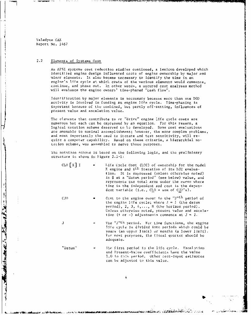
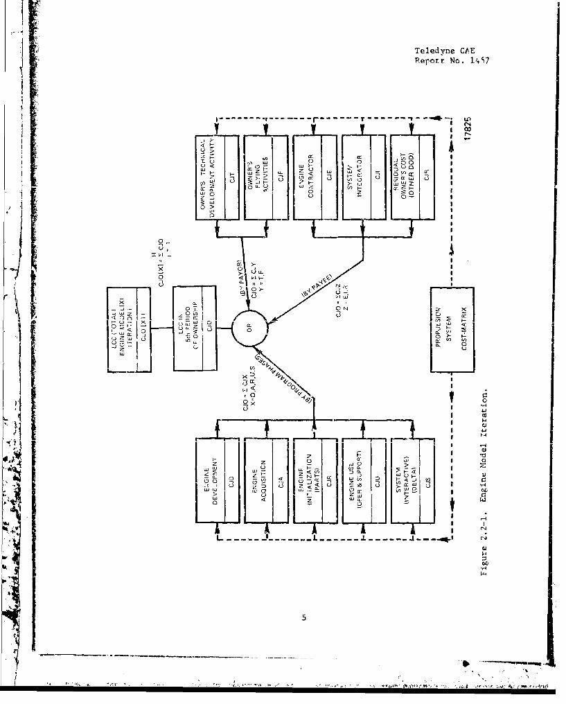
As APSI systems cost reduction studies continued, a lexicon developed whichidentified engine design influenced costs of engine ownership by major and-ninor elements. It also became necessary to identify the time in anengine's life cycle at which costs of the various elements would commence,continue, and phase out. In other words, a matured cost analyses methodwill evaluate the engine owners' time-phased "cash flow".
Identification by major elements is necessary because more than one DODactivity is involved in funding an engine life cycle. Time-phasing isimportant because of the combined, but partly off-setting, influences ofpresent value and escalation value.
The elements that contribute to or "drive" engine life cycle costs arenumerous but each can be expressed by an equation. For this reason, alogical notation scheme deserved to bo developed. Some cost evaluationsare amenable to nominal accomplishment; however, the more complex problems,and most importantly the need to iterate and test sensitivity, will re-quire a computer capability. Based on these criteria, a hierarchial no-tation scheme, was assembled to serve those purposes.
"the notation scheme is based on the following logic, and the preliminarystructure is; shown in Figure 2.2-1:
CLO [X] I Life Cycle Cost (LCC) of ownership for the model
X engine and ith iteration of its LCC evalua-
tion. It is expressed (unless otherwise noted)in $ at a "datum period" (see below) value, andrepresents the total area under the curve wheretime is the independent and cost is the depen-dent variable (i.e., CLO = sum of CJ0's).
CJO Ccst to the engine owner in the "j"th period ofthe engine life cycle; where J = I (the datumperiod), 2, 3, 4,..., H1 (the horizon period).Unless otherwise noted, present value and escala-tion (+ or -) adjustments commence at J = 2.
I:.J The "j"th period, Fur Lime functions, the enginelife cycle is divided into periods which could beyears (an upper limit) or months (a lower limit).For most purposes, the fiscal quarter should beadequate.
"Datum" The first period in the life cycle. Escalationand Present-Value coefficients have the value
1.0 in th's period. Other cost-input estimatescan be adjusted to this value.
4[
t,
Teledyne CAEReport No. 1S
0 a~
LC)~~u
L
j00
-0
:0
- ILI
r-rL~y~i .LiiL,,rL~am
ZW
0w
00
-LO
0
(L ~ 2
LJ
.4
0 -1F
- ) '-'0 Wa
tI
I.L _______ --- - - - -------- ---. -t
.
Teledyne CAEReport NG. 1467
"Horizon" The last period in the life cycle. Twenty-eight
yearly (or 100 quarterly) periods are typicalfor a trainer engine, and 15 yearly periods maybe representative of an RPV engine.
CLD, CLA Life Cycle Cost (total) of ownership for the
development and acquisition phases respectively.
P [CLD < X1 A probability statement utilized when technic.l-risk (See Sections 2.2-2 and 5.2), or when other
confidence-bounded estimates are addressed.
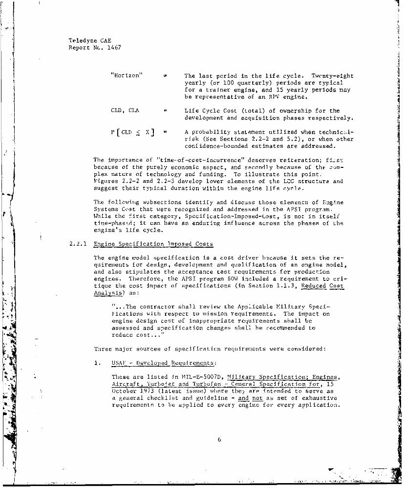
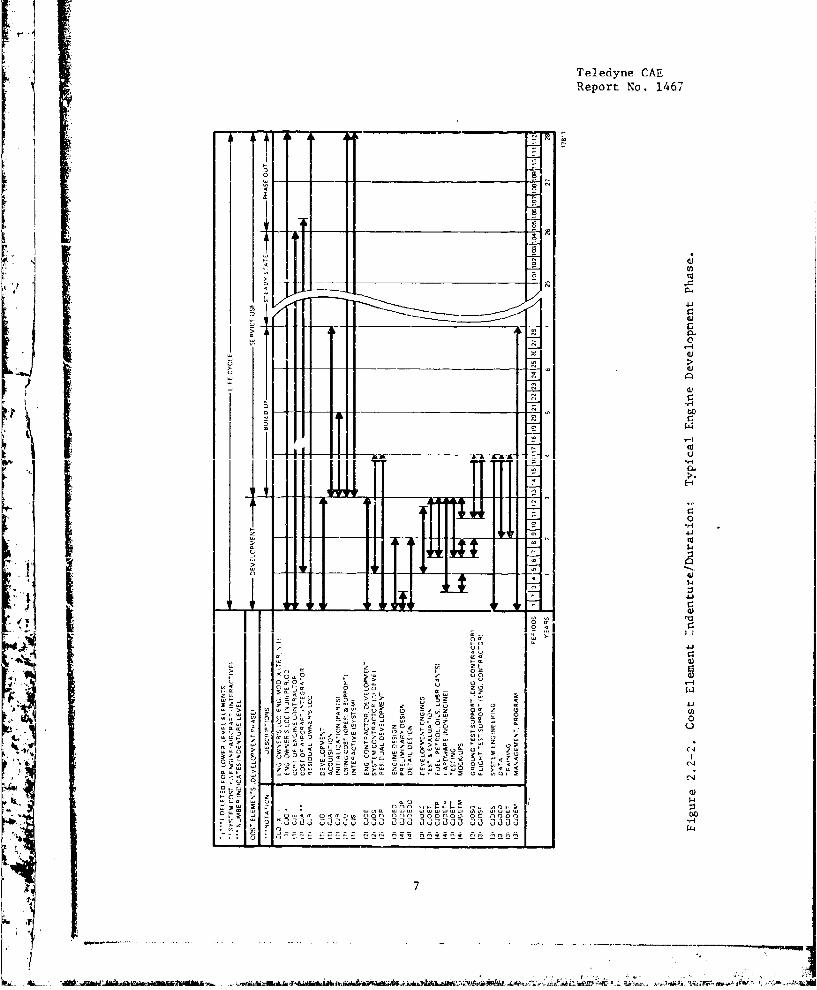
The importance of "time--of-cost-incurrence" deserves reiteration; fi~stIbecause of the purely economic aspect, and secondly because of the com-plex nature of technology and funding. To illustrate this point.Figures 2.2-2 and 2.2-3 develop lower elements of the LCC structure andsuggest their typical duration within the engine life cycle.
The following subsections identify and discuss those elements of Engi.neSystems Cost that were recognized and addressed in the APSI program.While the first category, Specification-Imposed-Cost, is not in itselftirne-phasrsi; it can have an enduring influence across the phases of the
engine's life cycle.
2.2.1 Engine Specification Imposed Costs
The engine model specification is a cost driver because it sets the re-quirements for design, development and qualification of an engine model,and also stipulates the acceptance test requirements for production
engines. Therefore, the APSI program SOW included a requirement to cri-tique the cost impact of specifications (in Section 1.1.3, Reduced CostAnalysis) as:
"...The contractor shall review the Applicable Military Speci-tications with respect to mission requirements. The impact onengine design cost of inappropriate requirements shall be
assessed and specification changes shall be recommended toreduce cost..."
Three major sources of specification requirements were considered:
1. USAF - Developed Requirements:
These are listed in MIL-E-5007D, Military Specificationl;Engines,Aircraft, Turbojet and Turbofan - Ceneral Specification for, 15
October 1.973 (latest issue) where they are intended to serve asa general checklist and guideline - and not as set of exhaustiverequirements to be applied to every engine for every application.
6
Teledyne CAEReport No. 1.467
04
a 0 (0
$4
'34
4A-.
0
-4
U, w
•1 q.,, On! 1'0 [• =•
' i (U(U" ti I-II1T llllP m -
Jac OJO 00 Jcc 00 90 33
0 1P4
ri to 2!- - -
" .7
AA".;,
Teledyne CAEReport No. 1467
Ifs
siW
--
VP
1411111 IA°h1
-) o - --.
a Ilo
4'
Ul
o
C'H•
a-a
Teledyne CAR
Report No. 1467
2. USN -Developed Requirements:
These are listed in AS 2684 - Military Specification; Engines, Air-craft, Turbojet and Turbofan, General Specification for, 30 December1970 (latest issue). This document serves a purpose similar to MIL-E-5007D for Naval aircraft engine procurement.
3. Airframer - Developed Requirements:
These are usually imposed on Contractor Furnished Equipment (Engines)or CFE as opposed to Government Furnished Equipment (Engines) or GFE.CFE specifications usually contain (and derive from) military require-ments. However, they also reflect, at times, requirements developedby the airframe contractor's specialist groups.
In undertaking a cost effectiveness critique of the foregoing specifica-tions, three salient facts were considered, i.e.:
1. Teledyne CAE recognized that these specifications represent theaccumulated experience of the military turbine-engine procurementand using activities. As such, the majority of their specificrequirements have come into being in response to service-revealed
2 pro.lems, some applicable to specific engine types and some to
engines in general.
2. The DOD specifications are specifically intended to serve as "check-lists" and guidelines for negotiatin- a specific model specification.So, the cost impact is actually determined by the resulting modelspecification and the judgment exercised by the procuring activityand engine contractor.
3. Very few model specifi(ations reflect blanket-use of DOD specifica-
tions; as evidenced by a review of current Teledyne CAE specificationsfor the J69/JlOO/J402 series of man-rated and non-man-rated engines.
I As a result of the review process, Teledyne CAE also developed guidelinesfor the task of developing model specifications for APSI-derivativeengines. These are addressed to the major sections of a general military(or contractor-equi',alent) specification as follows:
a. Performance Consiuerations. Model Specifications should be reviewedfor the cost impact of the operating envelope, particularly its"corners", Demonstrating a "corner" may become a "cause celebre"
to the point that it can double the cost of a planned test series,without contributing to the owaer's operational benefits. In mostapplications, the reviaw will require a coordinated effort that in-volves the air vehicle designer, the engine designer and the usingactivity. The costs (of development and acquisition) incurred byadvanced performance parameters (e.g., SFC) should be traded offagainst the ultimate benefits to the user.
9..v. - 1 "
Teledyne CAE[Report No. 1467
b. Mechanical. Design. The mechanical integrity requirements have adirect calcuable cost impact, and should be critiqued for the appli-cation. General requirements for "Structural Integrity" includeEngine Pressure tests, Low Cycle Fatigue, Containment, etc. 'aesetranslate into choices such aq; material quality and type, forgingsversus castings, rig test time and other considerations. Becausethey generally stem from prior, and often unfortunate experiences,they should be challenged with prudence. Nevertheless, these re-
quirements should be modified as appropriate to the mission andapplication.
c. Reliability, Durability, Maintainability and Design Life. Theseparameters are related and often confused, yet they are generallythe driving force in the maintenance and support cost elements ofan engine's life cycle cost. For that reason alone, they eachwarrant first a clear, unequivocal, definition and then a carefulevaluation based on design, material properties and intended use.We suggest the following definitions:
Design Life - The time, in hours or cycles, that an engine willoperate and complete a stated number of missions between ,ajvr
overhauls.
Reliability - The probability that the engine will complete thedesign life period without a shut-down, or major failure.
Maintainability - (Better described as "Maintenance Index") The
number of man-hours of maintenance per engine operating hour dur-ing the design life.
Durability - lnh probability that an engine, or part, undergoingperiodic inspection at stated intervals will be capable of returnto service. (This is more readily calculated for specific parts.)
d. Testing. The testing requirements of a model specification areusually referred to as Quality Assurance Provisions. They generallyinclude development and qualification tests. They may include pro-visionb for reliability and maintainability demonstration, and could
address "Durability". Finally, they prescribe quality assurance interms of the engine production acceptance test. This entire packagedeserves scrutiny because: when overspecified it raises the develop-ment cost, and, when underspecified, it can adversely affect theoperation and support elements of life cycle cost.
e. Systems Engineering and Data. Teledyne CAE has recently seen RFP
requirements containing Systems Engineering and Data requirementsthat promoted confusion and could have led to unnecessary cost indevelopment programs. This usually occurs when the procurement isCFE and the contractor passes on all government specifications,
10
Teledyne CAEFeport No. 1467
without screening, to all of its sub-contractors. In any enginedevelopment program, the various work package and data requirementsshould be coordinated between the procuring activity, the air vehicledesigner, and the engine designer.
f. Cost Trade-offs. In the process of critiquing specification require-ments, the total cost/benefits of a specific design feature, testplan, or •.erformance requirements should be determinable in quanti-tative measure. This task assumes the existence of a working"design-to-life-cycle" cost capability.
In Eummary, a systematic approach to specification cost impazts has beendeveloped, with specific emphasis on MIL-E-5007D and AS 2684. Appro-priate Teledyne CAE Specifications have been selected for the purpose ofcomparison, and subjects for detailed examination were identifiec, Atypical set of specification-imposed cost subjects was subjected to thesystems cost approach, which evolved during the program; with theresults described in Section 4.2.18 of this report.
2.2.2 Development Costs
A systems cost methodology requires precise definitions, if its calcula-tions and estimates are to be consistently understood and ancpptpd. Inthe broadest sense, development costs consist of all expenditures neces-sary to bring a design to a state of producibility. In a practicalevaluation, however, the conventions that exist in engine procurementshould be considered.
In a feasibility evaluation, an engine development is normally fundedafter some iuvestment such as; company IR & D/B c P, DOD exploratoryresearch, etc. A specific development model is then undertaken with so-called 6.4/6.5 funding, and carried through to a model qualificationtest (MQT), often with demonstration milestones such as the preliminaryflight rating test (PFRT). During APSI, we, therefore, developed thefollowing definition for Development Costs:
CLD = Cost of Development (total) = All funds paid to develop,test and then demonstrate that a specific engine model isready for production.
We also found that development costp have historically represented asmall percentage of the explicit cost of engine ownership; however,engine development cost also has a profound impact on aircraft systemcost. For example, the APSI studies identified the prospective savings:in life cycle costs of one representative aircraft summarized in Figure2.2.2-1. These resulted because the airframe was in a conceptual designphase and capable of being scaled down to benefit from improved engineperformance while keepiug the "mission" constant. The savings accrued in
11

ATeledyne CAEReport No. 1467
Engine Airframe
Parameter Improvement Cost Element Savings C% - 1974)
SFC 0.01 (one "point") Development - 14.05Acquisition - 85.95Maintenance -
Percent of Savings - 100
Weight 0.01 (one percent) Development - 12.27 1A
Acquisition - 19.62Maintenance - 68.11
Percent of Savings - 100
SFigure 2.2.2-1. Engine Influence on Airframe Cost.
airf:7ame development, acquisition and in aircraft life-time fuel consump-tion. This relationship of engine to aircraft interactive cost is furtherdiscussed in Section 2.2,5.
2.2.3 Engine Acquisition Cost and Design-to-Cost (DTC)
Summary
During the API APSI program, Teledyne CAE developed an engineeringapproach that addresses the problem of engine costs and Design-to-Cost(DTC). The method was tried and tempered by real time, "on-the-drawing-
board" use in the APSI component definition program. The company initia-ted DTC on APSI as a way of focusing engineering talent on the cost ofsmall gas turbine engines. Teledyne CAE has since used DTC to good ad-vantage in- the APL Low Cost Jet Fuel Starter design study; a replace-
ment engine for the J69 series; and the current cruise missile enginedevelopment program.
The approach to DTC recognizes that acquisition and initialization aremajor contributing elements to the total cost of ownership. Also, ini-tialization (stock set up) is a function of the number of parts in theengine and the cost of each parc. Therefore, reducing acquisition costand reducing engine complexity are mutually advantageous to total owner- Vship cost.
The DTC method evolved for the JTDE engine and component use is brieflyillustrated in Figure 2.2.3-1. A typical material removal curve thataids in selecting the proper material and manufacturing process for adetailed component is shown in Figure 2.2.3-1(a).
12
""4
Jt

Teledyne CAEReport No. 1467
I '~~-'~J
P -'
F~L _C_ _ _ _ _
ENGINESeUPT
UP ENGINE A
15604
()DTC: ENGINE COST GROUP. (d) DTC: ENGINE MODELS.
Figure 2.2.3-1. DESiGN-TO-COST APPROACH.
13

Teledyne CAEReport No. 1467
Figure 2.2.3-1(b) illustrates an inseparable part DTC worksheet - completedand iterated while the part is on the design board. The accumulated costsfor one engine "cost group" are listed in the DTC worksheet of Figure2.2.3-1\c). These DTC "Cost Group" worksheets are then assembled andused to produce the engine model work sheet (Figure 2.2.3-1(d)) that aidsthe Design Group Leader during progressively more rigorous technical andmanagement reviews.
The results of the DTC approach to engineered reductions of acquisitioncost are compiled in the illustration for comparison of an APSI derive-tive to a current engine, where the APS! derivative saves 35 percent in
eres the APSI Program have been developed throughprocess. Original costing methods only provided data
i - alues for comparing percentages or trends ofdifferent or s This process was found to be inadequatewhen the cost Me uctioh tacs were investigated in detail. This even-tually led to the establishment of a "Design-to-Cost" costing procedure toprovide the necessary detail for accurate cost comparisons. The considera-ticns addressed in the development of this method were:
- It must provide sufficient detail to be useful for the appropriatephase of design.
- The method should be compatible with manual as well as data pro-cessing compilation procedures.
- The approach must provide the manactivitywith sufficient information to c W gn intent and con-tribute to achieving the cost obje
The method selected is based on identifying the finite enginecosC at tL part deig l l,-ng- .c'4t-S±5LL design process, t •l ....... •manufacturing (or acquiring) each part is compiled by finite elements.The elements include the man-hours for individual manufacturing opera-tions, the material costs and the support costs (in man-hours and material)of inspection, tool support and certain overhead operations. Man-hourand material costs are entered as "burdened" values. Performance indicesand anticipated scrap rates are included for each operation, or summarized
for each part.
This method facilitates evaluating the cost consequence of changes indesign and/or manufacturing operations. It also allows for estimatingor specifying cost objectives as a function of production quantities anddelivery rates. Burdened rates are used for material and labor but theburden (overhead and material handling costs) may vary as a function of
14
S..-
Teledyne CAEReport No. 1467
the production quantity being estimated, However, all values are still in
terms of cost and not price (i.e., they do not include G & A or Fee). A
more detailed de.cription of the costing procedure was presented in APSI
briefing sessions.
In addition to the costing procedures described, data has been tabulated
in the DTC Cost Compilation Manual to provide the means of deriving the
material and fabrication costs for preliminary estimates by the design
engineer. The DTC costing procedures have the flexibility of allowing as
much or as little detail as the part.cdlar estimate requires. To pro-vide an engineering approach to costing, an effort was made to establishthe range and type of alloys expected to be used in the various engine
geometries studies, and to establish a means of costing these materials
based on current prices, form, and quantity. -
A listing of the most common metals, in their various forms, was made byselecting those materials being used in current production and developmentengines. Through direct contact with materials suppliers and through the
utilization of their price listings and current cost estimates, the
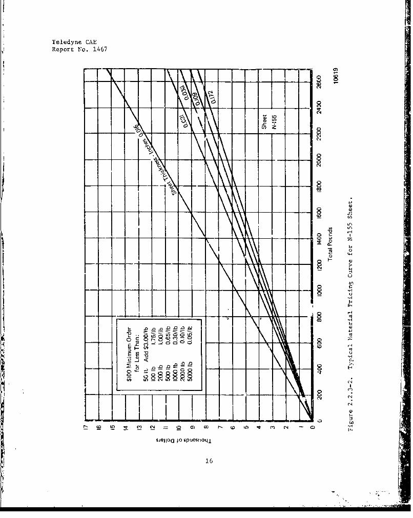
materials costs were gathered and plotted. The resulting curvt:i reflectbase prices. Because base price is somewhat modified by sheet thickness,
bar size and purchased weight, several curves were plotted, where appro-priaýte, 90 that interpol•tLlib: could be performed. In addition, a tabu-lation was included on the curve to correct the pricing of small order lots.
A typical materials pricing curre is illustrated in Figure 2,2.3-2.
Castings do not fit into any nornal manufacturing process such as drillingor milling. In addition, they are subject to many cost variables which
result from techniques of pouring, number of cores, thickness of walls,and the like. Therefore, castings are considered to be a unique materialform, and have been priced in a,manner that is appropriate to that form.Prices of castings, ryor to an4 subsequent machining or processing, were
gathered from currently known vcr~dor quotes and costs. The castings
selected were reptesentative of various nickel, iron, aluminum, or cobaltal]nvR. an- were rep escrt ... . LL the vaeious component forms, such as
spinners, turbine rotors, oil pump housings or nozzles. After screening
the information in rough plots to establish cost trends, numerical valueswere assigned to the various factors of casting difficulty.
Complexity factors have also been established for forgings of variousmaterials appropriate for use in gas turbine engines. An effort has beenmade to establish a means for costing all material previously used in
this industry, Additional new alloys and/or fabrication techniques will
continue to be incorporated as necessary.
1
Teledyne CAEReport No. 1467
(0
CC'4
(.).)
CC
0.0
I co
- - -- --0 --
- -- Z7
LO L
0~ C: CJE
E '0
(/) 00 2-0 i)q m C
s~juloa o suesrot8
16.
T eledyne CAE
Report No. 1467
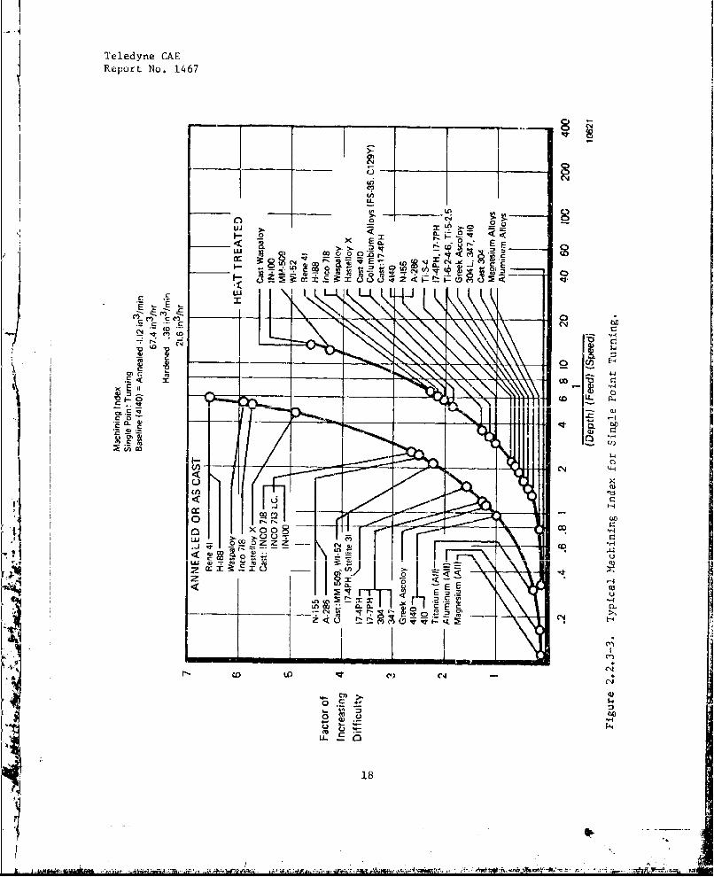
A similar effort has been made to establish a means of costing the vari-ous manufacturing operations utilized in engine fabrication, It is wellknown that the ease and effectiveness of manufacturing processes varybroadly with base metal, alloy and heat treat. In order to properly assessthe cost effect of these variables, some measure of variation in difficultyhad to be established. The machining statistics on the more commonmethods of manufacturi,, 6 were gathered from the Machining_ Data Handbook.Using the data supplied on the materials and methods appropriate to thepreseat program, tabulations were prepared for the various operationsusing heat treat conditions thst were expected to be encountered. Aplot of relative material removal rates for single point turning is shownin Figure 2,2.3-3. The ordinate, or the factor of increasing difficulty,is a dimensionless number, which when divided into the removal rate statedon the curve, will correct for the various alloys and heat treats.
Of course, some machining operations do not always fit the situation de-picted by idealized curves, so Teledyne CAE's Industrial Engineering Dataare us.ed in chose cases. This is evidenced in the case of hydrotel air-foil milling (Figure 2.2.3-4) which is peculiar to gas turbine fabrica-tion. Similarly, manufacturing processes such as electrodischarge machin-ing (EDM), electrochemical machining (ECM), welding, brazing, heat treat,
uuLfactb LLuLt and coatings have been reduced to time elements based onexperience. Manufacturing and material costs exist in a dynamic environ-,ment and are necessarily revised as changes occur in availability, capa-bility and/or producibility.
Uzfng the procedures and data described, in addition to vendor and manu-facturing engineer quotes, design engineering compiled the engine acqui-sition cost data presented in Section 3.0. These costs were all developed,sing these assumptions:
- Production quantities of 1,000 engine/year.
-V'ILL6 '.ULO Wer eALUULU.
-G A and profit were excluded.
- 25 percent G & A and 10 percent profit were assumed for systemcost payoffs on component cost reduction topics.
Tn addition to these assumptions, each of the missions analyzed providedtypical linearized weighting factors (for each delivered aircraft) forimprovements in weight and .•YC as related to dollar savings. These dollar
equivale arts were used to provide system cost apayoffs for the componentcost reduction topics.
I1
Teledyne CAEReport No. 1467
U, <
< ~0-so 2 L0 2-
<C " a z< _,E_,_tl
L. C
-- CO: M C( Z iD7 ,
EEi
(~LL
4)4
ch~
00
-*1 _
__ IIt,
.CEN
4V) C4
-4J
t774

Teledyne CAEReport No. 1467
II I IHydrozel Airfoil Milling! Slot ,og Ct, o to, 2 0 In ,de/4 (,Final Polish Not Included
Use Side Milling Indexto Correct Time forMaterial Changes Finish Mill
0 3." -I -II0 3
Note: Rough Mill Is NotNecessary for Forged Blade S i l
1
I• •• -'• "• "- I Finish badand Bln -1
10 20 30 40 50 60 70 80 90 100
Airfoil Surface Area - In 2
10617
Figure 2.2.3-4. IHydrotel Airfoil Milling.
19
. .- 'M L W g , : ; • -u
:; • •u, 5 ,
Teledyne CAEReport No. 1467
2.2.4 Operation and Support Costs
The APSI program provided a means to challenge the trends in total costsof engine ownership, and the cost of operation and support was alsoaddressed.
Two specific areas of operation and support were evaluated by TAledyne CAEduring the APL APSI program. These are:
Operational costs of the engine fleet (consists principally of fueland lubricant consumption).
Maintenance support costs including manhours, material (replacementpart) costs, and inventory management costs.
During APSI, the airframer's studies of engine/air vehicle interactionemphasized that fuel consumption should properly be addressed as an air-craft/engine interactive cost. Maintenance support costs, on the otherhand, are primarily determined by the engine designer in all areas withthe exception of "installed-engine-accessibility".
,,a4111ntars adancasth cost. prob-lem- ti-refore la tha-important aspects:
The development program for the JTDE and the "delta" developmentwill field a family of engines that are relatively mature in termsof verified reliability and durability,
The engine family concept reduces the number of parts and spreadsthe inventory monagement cost ($120/part-typeiyear) across thehighly common engine types,
The inherent simplicity of the 455 series will reduce maintenance
The low acquisition cost reduces lifetime engine and component
replacement costs.
2.2.5 Performance (Interactiveý Cost
The Teledyne CAE subcontracted (APL APSI program-sponsored) aircraftengine studies addressed the task of selecting optimum engine/aircraftconfigurations. An important spin-off of these studies was the recogni-tion that an engine's form and function hayw significant impact on thedevelopment, acquisition and lifetime ownership costs of the air vehicle.
These results are not remarkable when the cost of aircraft materials isconsidered, but derived values of their slopes (e.g., air vehicle costversus engine weight/SFC) become very significant for smaller aircraftand engines.
20
Teledyne CAEReport No. 1467
The initial effect impacts airframe acquisition cost as a function ofengine weight and SFC. However, these initial effects of engine per-formance are carried through the life of the air vehicle. For example:
Airframe lifetime maintenance costs are partially a function of air-craft weight, which is initially sized by the SFC and weight ofavailable engines.
Mission and lifetime fuel consumption are affected by engine SFCand engine thrust-to-weight, because both SFC and the latter ratio"size" the airframe and its maximum fuel capacity.
The APSI program addressed both SFC and thrust-to-weight ratio to developengines providing significant improvements in these two airframe-inter-acting parameters, as well as on their trade-off with engine acquisitioncosts.
K
21
- .•-,~ -*t* . *fl ,,--J. <•. ¾ •

1 71
APSI Cost Reduction
22
Teledyne CAFFPeort Nc'. J46~7
SECTION 3.0 - APSI COST REDUCTION
3.1 Background
Approaches for addressing the performance, cost, and design-life of pro-pulsion systems require carefully directed use of an iterative process.Thig process begins with definition of potential application! and theirbroad range of performance requirements. It follows with a definitionof aerodynamic and thermodynamic considerations which, in turn, -ntablisncross section, size, volume, and mechanical characteristics of/4he pro-posed engine. The first baseline design then provides the Y1ference forparametric evaluations (with respect to requirements), sensitivity deter-minations, and cost investigation tradeoffs.
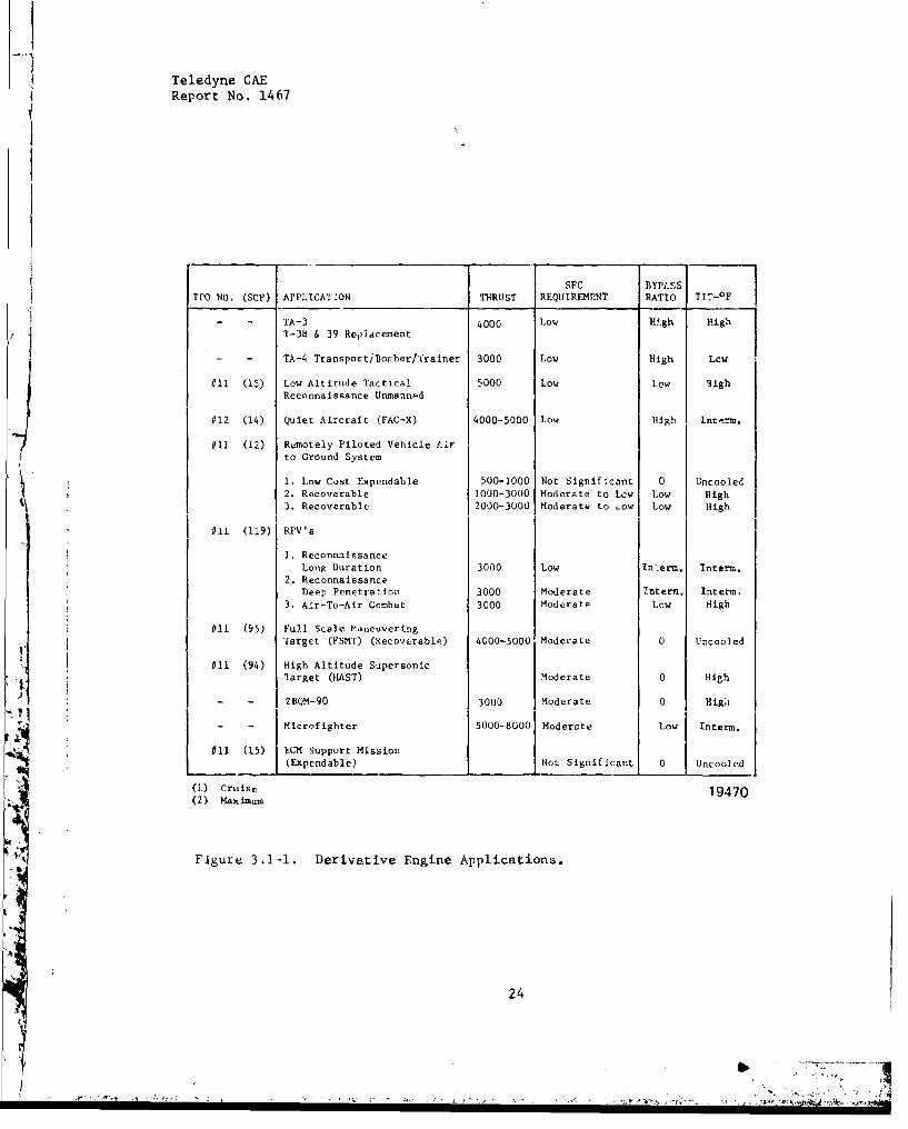
The APSI series of engines extends the basic design approach of theAdvanced Tutbine Engine Gas Generator (ATEGG), which results from theabove described iterative process. In ATEGG, Teledyne CAE considered arange of prospective engine-derivative applications as listed in Figure3.1-1. The application considerations provided direction to pursue theunderllying objective of advancing the technology level of engines in thethrust class of interest. Because of the long period of expected develop-ment and therefore the likelihood of changes in specific performance re-quirements, an additional requirement was identified. This requirement wasthat the gas generator be highly flexible and compatible with a wide rangeof future performance requirements. These considerations established theset of performance requirements.
The qualitative objectives for the ATEGG required a series of quanti-tative evaluations and commitments. For example, it was assumed thatprospective missions would require good SFC, for either life cycle costimprovement or adequate loiter time and range. Hence, at least some455 engine derivatives would require very low SFC's.
Compressor configurations were therefore evaluated to select a designthat offered the desired pressure ratio and efficiency at the least costand weight. Seventeen candidate configurations were thoroughly examinedprior to final selection. Comparable evaluations were conducted tooptimize other components. Contact with USAF/APL Plans and ProgramsOffice further substantiated the future need for engines in this class.Sufficient requirements data were made available to validate the designchoices.
23
J44 . ... . .... ....
Teledyne CAEReport No. 1467
SSFC BYPASS
TPO NO. (SCP) APPLICATION THRUST REQUIREMENT RATIO TIT-0F
TA-3 4000 Low Lwgh High, lT-3b & 39 Repldcement
TA-4 Transpor ti Boiber/Trainer 3000 Low High Low
611 (M15) Low Altitude actdeat 5000 Low Low HighReconnaissance Unanned
#12 14) oQuiet Aircraft (FAC-X) 4000-3000 Low High Interm.
#11 (12) 2 Remotely Piloted Vehicle eir,] to Ground System
D. Low Cost Expendable 500-3000 Not Sdgnifecant 0 Uncoolte2. Recoverable 1000-3000 Moderate to Low Low High3. Recoverable 2000-3000 Moderate to 0ow Low High
#11 (119)i RPV's
1. Reconnaissance
Long Duration 3000 Low In:erm. interm.2. Reconnaissance,
beep Penetration 3000 Moderate 0nterm. Interm.3. Air-T(-Air Comb5t 30000 Moderate Low High
#11 (95) ]Full Scale Maneuvering
Target (FSMT) (Recoverable) 4000-5000 Moderate 0 Uncooled
11 (94) High Altitude SupersonicTarget ((AS)) Moderate 0 High
F ZBQM-90 3000 Moderate 0 Higi
(1 5) EC-M support Mission(Expendable) Not Sign ificant 0 Uncooled
(1) Cruise 19470(2) Maimum
Figure 3.1-1. Derivative Engine Applications.
24
Teledyne CAERetport No 1467
A specific dollar cost target was not established for ATEGG or itspossible derivatives. However, a second underlying objective was toestablish the lowest inherent cost for a given performance objective.Tradeoff studies were conducted to this end. The expected result isthat the best cost pay-off will result from simplifying the flowpath,eliminating stages, and emphasizing the use of near-size forgings andcastings to minimize the ratio of raw material weight to fly-away weight(or Fly/Buy Ratio).
In summary, the challenge to mechanical design for a man-rated ATEGGderlvntivc resulted from consideration of performance, long range cost,and optimum utilization and return from development engineering effort.The response evolved as a man-rated engine, having a highly-loaded axi-centrifugal compressor and single-stage cooled turbine.
3.2 Baseline Engines
A single model was selected as the baseline engine for the APSI coststudies. It is a potentially optimum propulsion system for a low leveltransonic mission, combining a relatively high fan pressure ratio with amoderate bypass ratio. The design also envisions a relatively high tip3pccd and high fan stage turbine loadings to 1,iAt the it,,urmbe of low pieu-
sure stages. This provides a compact, high performance design. Thisdesign, with a minimum number of components, provides an inherently lowcost baseline engine against which all cost reduction items have beenevaluated.
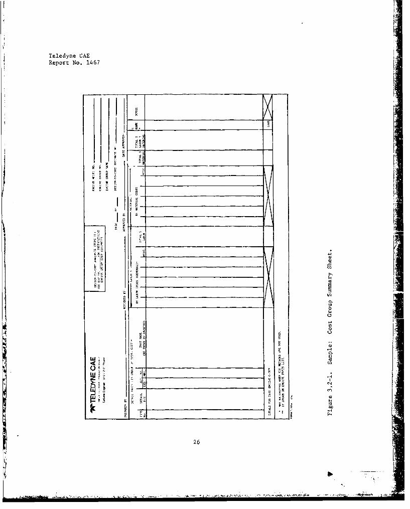
For cost reduction purposes, the engine was divided into ten componentassemblies which defined the cost groups. The cost groups were furtherbroken down into the components which make up a given cost group. Thisprocedure ensured that all the necessary engine hardware was accounted forand that none were overshadowed by relative high cost items of other com-ponents which represent the 80 percent/20 percent group. The cost groupsummary sheets (sample illustrated in Figure 3.2-1) enumerate the parts onthe 80 percent/20 percent factor where 20 percent of the parts represent80 percent of the cost of each individual group. The remaining parts arethe miscellaneous parts which represent 20 percent of the grcup cost andwere not cost itemized. Each of the cost parts has been estimated in de-
tail. An example of the detail part cost work sheet is shown in Figure3.2-2. The detail cost worksheets were used to provide the cost inputsfor the group summary sheets. These group summary sheets, In turn, wereused to compile the engine cost estimate (Figure 3.2-3). Parts costs werethen used to provide tradeoff comparisons for component cost reductionitems as applicable.
3.3 Scaled Engine Costs
The baseline engine selection was made using the same philosophy appliedin the selection of the gas generator for the ATEGG program. The engine
25
I I
Teledyne CAE
Report No. 1467
I p-• I _ __________________________
I• - 4- [--4 0)
0
I 00
26

Teledyne CAEi
Report No. 1467
w .
I.Ay.
41.L
41,U
c--i
27

Teledyne CAEReport No. 1467
'W 1 L D N CAE 1ENII.-N-TN.1TIT ANLYSIS FORM (TYPE 1)EI.I. f 11 t.1 N0 ________
TA.O tOlLr gt, . 1 I IA WI A
P5.101, 1)101 AVIl N,), u1.%0 NI, SP-FIATIO NO1111 . REV_ N.0.__ STANUS OF ESTIPMATE _______
QN RL AllA _ _l. i.L I
TONAL iSAT 01 ~ INALSETEUIF VARIANTf
ULLY (NATl ANO 'I NIMIEm AL ENA5 -L I SNS 1 11 U5T $ 1,3 O
ANNE E FInN , IAf FIILII.IN
I Y1 A. MNC. MA)1AIIA ~ -
5 TOTAL fOTN.N A" AlfCf IIIs - -
AN IM NILEAIFIF 1.
'1 IIMALL NI- IAA I
,I) -nl I 0.11,111 IN TEITAIL PANT 151 [NATES. LEISENI NI. IUV AlOEAIiIsTIN` (ATTAIN ANALSIS)TI
(AN 0AL101 HAu ANIAK. I-NINIA NTI ASHIPPi1, I ES] 11701M. PgO70(1INON INUA"lEPANTS FUR 1111 CN$1ICNRATNNI- ) iMAL 4o. ON 0/11 INI ON GIlS
11, IFAR-iIA iS lINEN. OR/ N IE UNU0N.
(31 AARIA(LF (70 (TAhGLT -ACT UAL/ TAIILET) A INNO. ,SA
IA) 1ISIM N1N RSAN1, ONN _______
Figure 3.2-3. Sample; Engine M'odel Cost Estimate.
* 28
Teledyne CAEReport No. 1467
components had to be extremely versatile and readily scalable. To
develop cost data for scaled versions of the baseline engine, a twice-thrust scale and a one-half thrust scale were selected.
3.4 System Cost Reduction
3.4.1 Summary
During the APSI program, Teledyne CAE addressed a number of system costconsiderations in optimizing the engines for aircraft applications. Toassist in this task, Teledyne CAE funded two airframer studies that de-fined optimum aircraft/engine combinations for a future undergraduatepilot trainer or UPT (representative manned mission), and for a multi-mission remotely piloted vehicle or MMRPV (representative unmannedmission). The UPT and MMRPTV missions were selected as benchmarksbecause:
The UPT bounds the "high end" of the mission spectrum in termsof annual utilization and total life.
The IPRPV has good prospects for near term development and it boundsthe low-end of the mission spectrum,
The mission studies highlighted the influence of engine optimization onan air vehicle's total lifetime cost of ownership. The studies suggest,for example, that the interactive (engine impact on airframe design) costsmay equal or exceed the (more generally recognized) explicit costs ofengine ownership during the air vehicle lifetiie. The studies also indi-cate that only one to three percent of the totaj cost of engine ownershipis available for development test and evaluation, which emphasizes theleverage of engine development on lifetime costs.
The foregoing considerations led to the selection of cost-optimum designto:
Combine the ATEGG with the APSI-sponsored fan turbine andcompany-d'veloped fan to derive a turbofan engine parent toa variety of derivative turbofan engines.
Serve as a realistic, engine-operating environment for evaluat-ing the systems payoff of reduced-cost engine components,
The selected engine provides the best baseline for low cost derivativesbecause it is inherently low-cost in its own right. Notable features are:
29
$!
Teledyne CAEReport No. 1467
The mechanical arrangement usas a minimum of parts.
The fan and HP compressor are designed for casting to reduce initialmanufacturing and lifetime replacement costs.
The fan turbine is designed by cost drivers.
The counter-rotating LP shaft reduceb gyroscopic loads on both
engine and airframe, reduces the stiress (and cost) of mounting pro-visions, and simplifies (and reduces cost of) the low pressure spoolturbine inlet nozzle.
The selected engine can be tailored, by scaling and/or component modifica-tion, into a low cost powerplant for a wide range of future 4equirements.Its span of applications includes the unmanned bQRPV through the mannedand heavily used UPT. The potential cost leverage of APSI technology isexemplified by the data shown in Figure 3.4.2.
The maximum payoff from APSI technology will require careful matching ofderivative engine designs to their potential aircraft applications. Tothat end, Teledyne CAE has evolved a method fot evaluating system costs(Section 2.2.3). This approach was used to evaluate the Teledyne CAE
MMRPV and UPT candidates. It was al~o used to evaluate candidate enginecomponents that sbow good prospects for further cost reduction in severalof the baseline saries of engines.
The results demonstrate that fully discounted lifetime savings from thefirst two APSI-derivative development, programs would "payback" 20 timesthe Military Services' investment in exploiting technology to reduceengine systems cost.
3.4.2 Mission Definitions
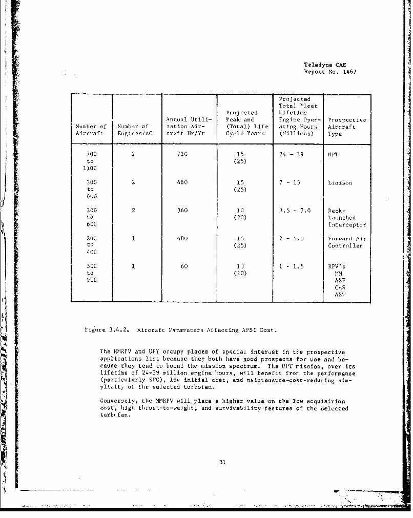
The mission spectrum for the selected derivative engine spans a wide
range of future military aircraft requirements. Missions, utilizaticnrates and total life cycles will vary, and will therefore require indi-vidual evaluation of systems cost at.d benefits. An illustration of
N their variety ard diversity is shown in Figure 3.4,2, which tabulatesseveral aircraft parameLers that impact life cycle cost.
The fleet size, utilization and life span estimates in Figure 3.4.2are based on Teledyne CAkE records for comparable present day aircraftsuch as the T-37 (J69-T-25 engine) and special purpose aircraft (SPA's)that incorporate the J69-T-29, J69-T-41, J69-T-406, and JI00-CA-100.Also, best utilization rates are shown for manned aircraft because theyrepresent good DOD cost reducing strategy.
30
Ti
IITeledyne CAEReport No. 1467
Proj ec tedTotal Fleet
Projected LifetimeAnnual Utili- Peak and Fngine Oper- Prospective
Number of Number of zation Air- (Total) Life ating Hours AircraftAircraft Engines/AC craft Hr/Yr Cycle Years (Millions) Type
700 2 720 15 24 - 39 UPT
to (25)1100
300 2 480 15 7 - 15 Liaisonto (25)600
300 2 360 ]0 3.5 - 7.0 Deck-to (20) Launched600 Interceptor
200 148U 15 2 - b.o Forward Air
to (25) Controller
400
500 1 60 13 1 - 1.5 RPV'sto (20) MM900 ASF
CASASV
Figure 3.4.2. Aircraft Parameters Affecting APSI Cost.
The MMRPV and UPT occupy places of speciai interust in the prospectiveapplications list because they both have good prospects for use and be-cause they tend to bound the mission spectrum. The UJIT mission, over its
lifetime of 24-39 million engine hours, will benefit from the performance(particularly SFC), lo-. initial cost, and m~intenance-cost-reducing Sim-plicitý of the selected turbofan,
Conversely, the MMRPV will place a higher value on the low acquisitioncost, high thrust-to-weight, and survivability features of the selectedturb. fan.
3,.
Teledyne CAEReport No. 1467
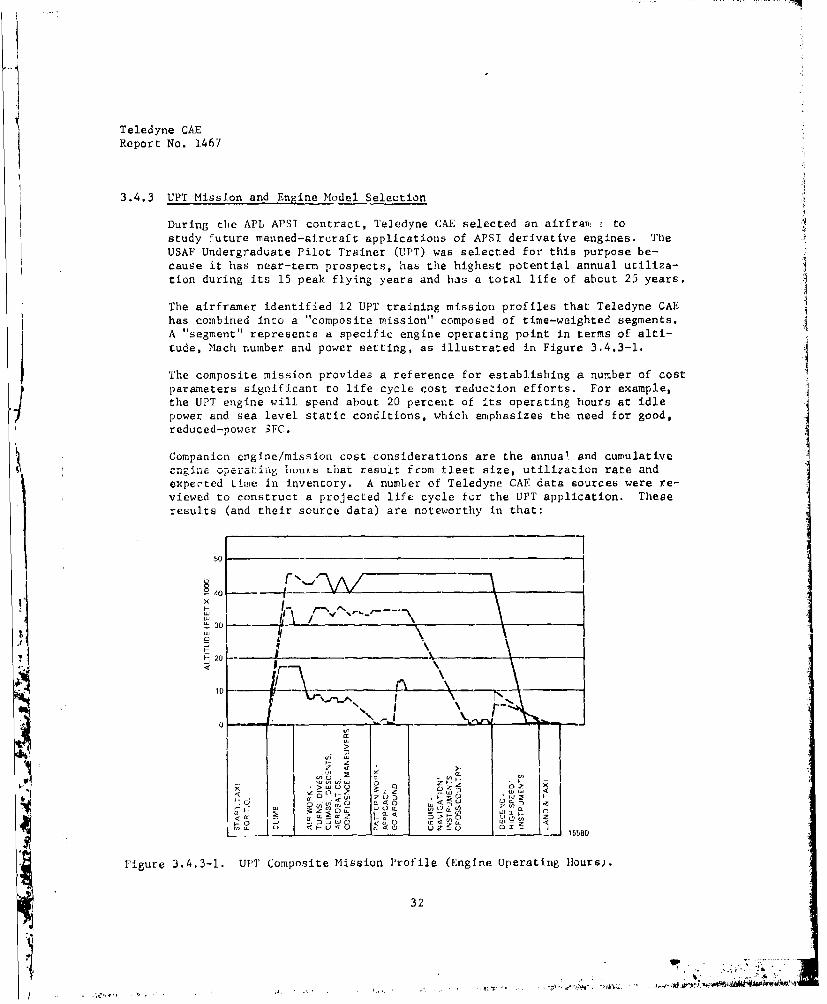
3.4.3 UPT Mission and Engine Model Selection 3
During the APL APSI contract, Teledyne CAE selected an airfraw tostudy future manned-aircraft applications of APSI derivative engines. TheUSAF Undergraduate Pilot Trainer (UTPT) was selected for this purpose be-cause it has near-term prospects, has the highest potential annual utiliza-tion during its 15 peak flying years and has a total life of about 25 years,
The airframer identified 12 UPT training mission profiles that Teledyne CAEhas combined into a "composite mission" composed of time-weighted segments.A "segment" represents a specific engine operating point in terms of alti-tude, Mach number and power setting, as illustrated in Figure 3.4.3-1.
The composite mission provides a reference for establishing a number of costparameters significant to life cycle cost reducion efforts. For example,the UPT engine will spend about 20 percent of its operating hours at idlepower and sea level static conditions, which emphasizes the need for good,reduced-power SFC.
Companion engine/mission cost considerations are the annual and cumulativecnrginaF operatinLg iunurs that resuit from tieet size, utilization rate and
expected time in inventory. A number of Teledyne CAF data sources were re-viewed to construct a projected life cycle ior the UPT application. Theseresults (and their source data) are noteworthy in that:
4oI-40
f- 0 --- l____ ___ ___ '__ ---__ ___
i if
-.-. " I -
10 -
zu: ,,I--O '
V- <~~ Vcas 0
Figure 3.4.3-1. UPI' Composite Mission Profile (Engine Operating 11ours).
32
-- - -~ . -j ~ -- i .~-'.t
Teledyne CAEReport No. 1467
The total life of a UPT can exceed 25 years, while its peak life
of 15 years will account for about 78 percent of engine usage.
The UPT's expected utilization of 60 hours a month w11 make ita cost-effecjive trainer aircraft.
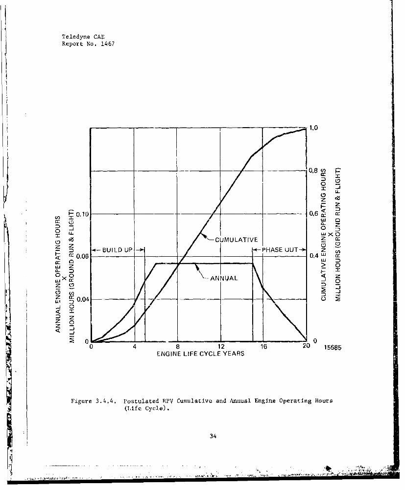
3.4.4 NMRPV Engine Selection
During the APL APSI contract, Teledyne CAE selected an airframer toperform system studies of a future unmanned derivative application. TheAir Force's Multi-Mission Remotely Piloted Vehicle (MMRPV) was chosenfor this purpose, and the airframer identified a number of air vehicleand engine candidate configurations. A mission optimized MMRPV was thenselected, and engine configuration was evolved to fulfill its require-ments.
An MMRPV engine life cycle was also postulated from Teledyne CAE's databanks on drones, special purpose aircraft and RPV's. A typical RPVengine life cycle is shown in Figure 3.4.4, which graphs annual andcumulative engine hours versus life cycle years. The plotted value of
Sone million hours for MIfRPV engine life tends to be conservative becauseof the increasing number of uses identified for RPV's. A probable upperlimit is likely to approach seven million engine life hours (typical ofa tactical aircraft), as RPV's tend to fill tactical roles and missions.
3.4.5 System Cost Comparisons
A principal objective of the APSI is reduction of DOD real engine-ownership costs. Durin,3 the APL APSI program, these costs wereexplored in a number of studies. Two studies of airframe-engine costinteraction were supported by airframe-contractor efforts. Other studiesinvolved Teledyne CAE research. Two of the many conclusions deserveparticular mention:
The real costs of engine ownership must include consideration ofits impact On Eir vehicle cost.
Only one to three percent of the total coat of engine ownershipis devoted to engine development - but savings from properlydirected development engineering can exceed 20 times the develop-ment investment.
33
Teledyne CAE
Report No. 1467
T 1.0
0.8 (n
U-
z
F-__ 0.10 0 _ _ -. 6~ c c
0 00
( eCUMULATIVE Z2Q
BUILD UP -*PHASEUOUT zC 40.08 0---.4w u
10 I I ILUz >0C
00ANNUAL <
Uj 00 .
U1 34
<~ _j

Teledyne CAEReport No, 1467
These conclusions were substantiated in a comparison involving two deriva--tive engines and their current-technology counterparts. For comparisonpurposes, one ATEGG derivative was compared to a high bypass ratio enginefor the UPT mission; and another was compared to a turbojet engine for the*WVPV mission. The current enginec were selected on the basis of theclosest fit available for the applications. Also, best estimates of theircharacteristics were used.
Engine parameters of interest are those with large, first-order, costimpact. These are listed for both the APSI derivatives and their currentcounterparts in Figure 3.4.5-1. The ownerchip parameters and commentsrelating its use in estimating engine ownership cost impact are listedin Figure 3.4.5-2.
These comparisons were made on the basis of individual, linearized esti-maLxs; the important effects of multi-parameter sensitivity were beyondthe scope of current tasks. Teledyne CAE recommends that mutli-parametere~fects be addressed as an element of the Design-to-Life-Cycle-Costmodel dehcribed in Section 5.0 of this report.
35

Teledyne CAEReport No. 1467
n 00
1-4 b-4
P4
PI,-I
;66f
to CIO z. ~0 -I) C) (12 u
C) a
Il 411 0 r 0-(.) C,.' M r b-
0~ 00
'I ' " . :0 r C lm 0i w rrw
0,0Id~OH' 040
,,4 £4 C Z£4 ld C uO£ -1 >: C.~ w- 0
E~OU E~OUOJ w O0C 4 E Ot~~*HCr Cm.A 4' 4 (,- W i.
36

Teledyne CAEReport No. 1467
PARAMETER COMMENT
(i) FUEL Current Military Price - $0.39(1.1) JP-4 Per Gallon of JP-4 at Nozzle(1.2) Booster Launch/ib of Engine Can also vary with SFC (MMRPV Only)
(2) AIRFRAME DEVELOPMENT*UPT
(2.1) **Per lb of Engine Relatively Insensitive to Fleet(2.2) 9'Per point (0.01) SFC Size
eMMRPV(2.3) *4Per lb of Engine Implicit in Vehicle Production
(2.4) sePer point (0.01) 5FC Cost (see Figure 6.5-3)
(3) AIRFRAME ACQUISITION*UPT
(3.1) **Per lb of Engine Based on "Nominal" Fleet(3.2) G*Per point (0.01) SFC
MMR[PV(3.3) l*Per lb of Engine Based on "Nominal" Fleet
(3.4) sePer point (0.01) SFC
(4) AIRFRAMIE MAINTENANCE NOTE: Following should also be( UPT sensitive to SFC improvements
(4.1) 'ePor lb of Engine
No "credit" for residual airframe@M'MDRPV weight savings
(4.2) --Per lb of Engine Best (most conservative) estimate
(5) ENGINNE MAINTENANCEI(5.1) *Dlrect Labor Estimate Range - $5-17/11our(5.2) *Material Estimate Range - 0.04 - 0.10%/Year
of Engine Acq.isition Cost (CA)
Figure 3.4.5-2. Parameter Values for Estimating DerivaLive Engine System CostSavings.
37

Section 4.0
Cost Reduction Analyses
3
38

Teledyne CABReport No. 1467
SECTION 4.0 - COST REDUCTION ANALYSES
4.1 AERODYNAMIC TRADEOFFS
The cost reduction analyses were conducted in two stages: analysis ofaerodynamic design parameters influencing cost; analysis of specificcost reduction topics for design and manufacturing changes to reduce cost,reduce weight, or improve performance yielding a minimum system cost.
Application of aerodynamic design tradeoffs in the selaction and optimi-zation of component designs can have a significant system cost impact.
4.1.1 Reduced Cost Parameters for Compressors
This analysis has the objective of extending cost reduction by definitionof cost related paramcters for LoAIFecbv• and Lu define generalized curvesor relationships representing a best estimate of the effect of these para-meters on aerodynamic performance for a single-stage compressor. Stagematching effects were not considered. Only design point performance changeswere considered.
Estimates are presented herein on the effects of tip clearance/span ratio,blade surface finish-to-chord ratio and rotor solidity ratio, correctedflow and efficiency. Also discussed are the effects of rotor aspect ratioand blade edge thickness. For centrifugal stages, the effect of tipclearance on pressure ratio, airflow and efficiency is indicated.
Table 4.1.1-1 presents an example of the performance degradation of atypiald J..e±edyne CAE axial compressor first stage due to the effects ofthe above parameters.
4.1.1.1 Effect of Tip Clearance/Span Ratio for an Axial Stage
The data for tip clearance effects were obtained from References 1 through5. The performance degradation model was developed assuming that no per-formance changes occur when the tip clearance ib less than or equal tothe boundary layer displacement thickness as determined by the designannulus wall blockage.
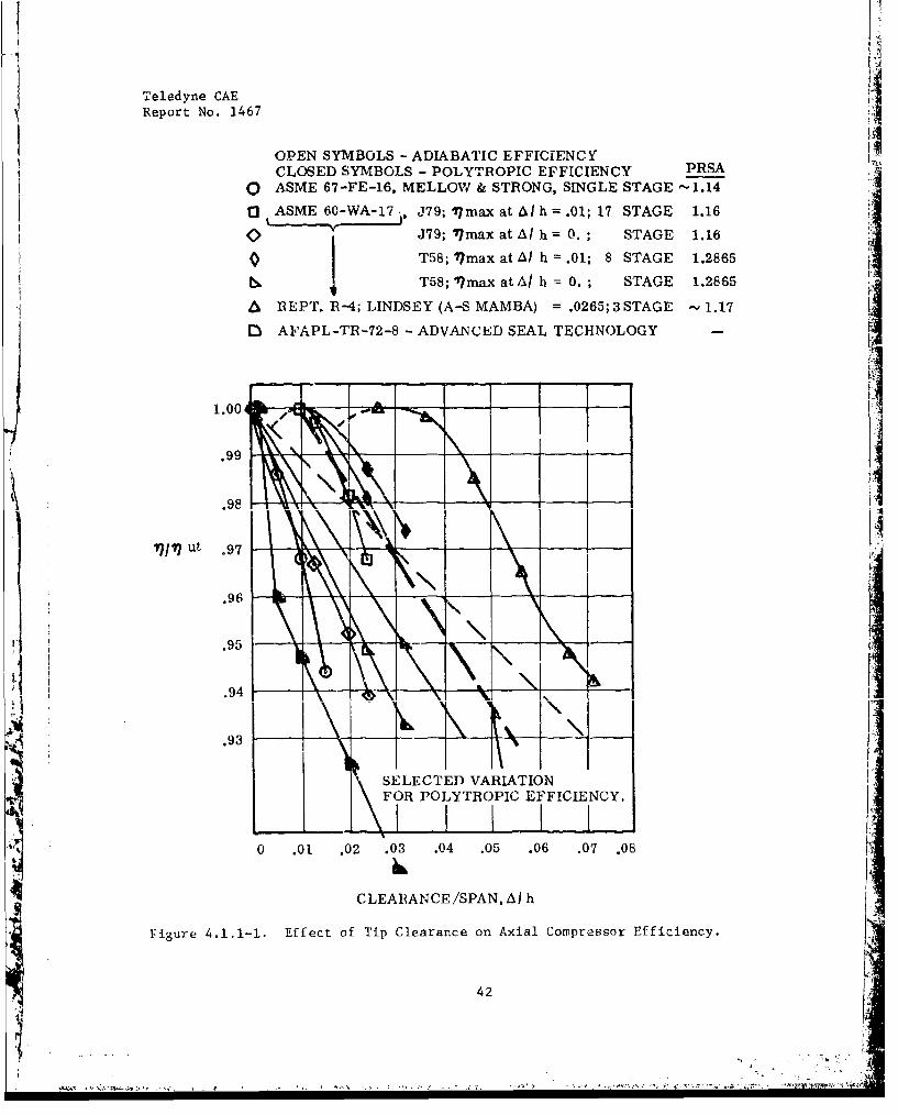
Effect on Efficiency - Efficiency degradation versus tip clearance/spanratio data is shown in Figure 4.1.1-1. For the selected variation ofpolytroplc efficiency, derated stage adiabatic efficiency is given by:
39

Teledyne CAEReport No. 1467
TABLE 4.1.1-I
PERFORMANCE DEGRADAT1ON EXAMPLE
PRESSURE CORRECTED ADIABATIC POLYTROPIC
RATIO FLOW EFFICIENCY EFFICIENCY
CASE CONDITION % of Ref. % 4,9(%) A M
1 Reference Design 100 100 Baseline Baseline
2 Same as Case 1, but 98.25 99.5 1.31 1.25
with doubled rotortip clearance
3 Same as Case 2, but 97.85 98.8 2.18 2.07
with surface finishincreased from 63
to 80
4 Same as Case 2, but 96.8 97.1 4.48 4.22with surface finishincreased from 63 lt
to 125
5 Same as Case 4, but 96.8 97.1 6.83with rotor leadingedge thicknessdoubled (assumeslimited redesignand/or up-scale)
40
'. ... .... .. .. .. ... -• --
Teledyne CAEReport No. 1467
(Y-1) /'17ad' PR' - 1.
i1 n P R'e Y 77p'
Where
77p' = 7p, ref* (1. - 1.5801 (b-c)),for b>c,
In PRre
?7p, ref = /(Y-1)/ 1In 1. + Ppref )
and/
?7ad stage adiabatic efficiency
77p = stage polytropic efficiency
PR = stage pressure ratio
Y = ratio of specific heats for air at average temperature between stageinlet and exit
b T/hc = O/'
4l = tip clearance, inches
= tip boundary lavyer dispnlaement. tLhi(c.kIn.ess, inches
h = average blade span, inches
Superscript ' refers to derated performance at b > c.
Superscript ref refers to reference performance at b < c.
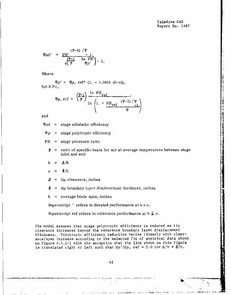
The model assumes that stage polytropic efficiency is reduced as tip
clearance increases beyond the reference boundary layer displacementthickness. Polytropic efficiency reduction varies linearly with clear-
ance/span increase according to the selected fit of empirical data shown
on Figure 4.1.1-4 with the excepticn that the line shown on this figure
is translated right or left such that 77p'/h7p, ref 1.0 for A/h 61/h.
41
Teledyne CAEReport No. 1467 .1
OPEN SYMBOLS - ADIABATIC EFFICIENCYCLOSED SYMBOLS - POLYTROPIC EFFICIENCY PRSA
0 ASME 67-FE-16, MELLOW & STRONG, SINGLE STAGE -1.14
(3 ASME 60-WA-17 i, J79; 11max at AL h = .01; 17 STAGE 1.16
0 .J79; 7max at A h = 0.; STAGE 1.16
0 T58; 17max at At h =.01; 8 STAGE 1.2865
T58; 17max atA/ b = 0. ; STAGE 1.2865
AREPT. R-4; LINDSEY (A-S MAMBA) = .0265;3 STAGE - 1.17
D AFAPL-TR-72-8 -ADVANCED SEAL TECHNOLOGY -
1.00 . - ____
.99
.98
171/) ut .97
.96
V I.95
.941
.93
SELECTED VARIATIONFOR POLYTROPIC EFFICIENCY.
0 .01 .02 .03 .04 .05 .06 .07 .08 -
CLEARANCE/SPAN, Al h
Figure 4.1.1-1. Effect of Tip Clearance on Axial Compressor Efficiency.
42
"q". .... •-- - - -
Teledyne CAER~eport No. 1467
Application of this model is limiited by the following considerations:
1. It is deduced primarily from multi--stage data.
2. Stage average pressure ratios for the data compressors, at from 1.14to 1.29, are considerably lower than current practice.
3. There are frequent omissions in the data as to whether clearancesare cold or running, as to whether they apply to rotors or statorsor both, and as to whether or not clearance/span was varied uni-formly throughout multi-stage machines.
4. Data scatter is considerable.
5. In certain data, the reference performance level w:is not optimum.
6. In some data, maximum performance was shown for zero clearance,while in other data, maximum efficiency was achieved at relativelylarge clearance to span ratios.
Effect on Corrected Flow - Reduction of flow should probably be consideredonly for an inlet stage. No data was found for effects on this peiform-ance variable. The proposed model assumes that flow is reduced in directproportion to one-half of the area difference between the tip clearance andthe reference boundary layer displacement thickness, where the referencedisplacement thickness corresponds to the design nssumption of annuluswall blockage. The derated flow is given by:
(WaVfO76)' (Wa\IO76) ref * (a- d) *(1 -d
for b)c, where. FT-I
WaVV16 = corrected flow
C = 2 Rm/h
Rm mean average rotor passage radius, inches
b, c and h, as well as sub - and superscripts are as definedpreviously.
Effect on Pressure Ratio - The model assumes that stage pressure ratio isreduced as tip clearance increases beyond displacement thickness. The onlydata available was that of Reference 4. Pressure ratio decreases linearlyaccording to the following relationship:
43
Teledyne CAEReport No. 1467
PR' = 1 + (PRref - 1) * (1 - 4.4 (b - c))
for b>c, where
PR = stage pressure ratio
b, c, sub - and superscripts are as defined previously
4.1.1.2 Effect on Blade Row Surface Finish for an Axial. Stage
The data for sutface finish effects on performance were obtained fromReferences 2 and 6. The effect of increasing surface roughness is thedegradation of all performance variables as the ratio of surface finish(ans in microinches) to chord (in inches) increases beyond a value of
••,,,•42.7. Surface roughnees is assumed to have no effect at lesser values.
It is assumed that performance is reduced according to a linear functionof this variable, based on empirical data,
Reference 6 showed that adverse effects of surface roughness decrease
with increasing speed, while thc opposite trend was observed in Reference2. Reference 2 was used as the basis for the development to follow.
Effect on Efficiency - Peak adiabatic stage efficiency is estimated to bereduced according to
77ad' = Y•p, ref* (i,0316 - 0.00074* (ft/C)) - 9.064* (PR - 1)1 - 8.887* (PR - 1)
for /!/C > 42.7, where
ft = surface roughness, rms, microirches
•' blade chord, inches
Other variables are as previously defined.
Effect on Corrected Flow - The data shows corrected flow at peak effi-ciency to be reduced according to
(WaVT/6 )' = (WaVJT ref* (1,021 - 0.000491* (ft/C))
for lJ/C > 4217.
44
S.~ §~4#V > ~ *1X~t.~> 4 1 ;4t
Teledyne CAEReport No. 1467
Effect on Pressure Ratio - Pressure ratio at peav efficiency is estimated
to be reduced on the basis of
PR' = 1 + (PRref - 1) * (1.0316 -. 0.00074* (p/c))
for /1/C 42,7.
4.1.1.3 Effect of Rotor Solidity for an Axial Stage
Two data sources have been screened for the effect of solidity on stageperformance.
References 7 and 8 document two NASA single-stage designs having rotortip solidities of 1.3 and 1.7, respectively, for the same design point andannulus geometry. Design rotor pressure ratio was 1.800; adiabatic effi-ciency was 0.89; weight flow was 29,484 kg/sec; and tip speed was 422.888m/sec. MCA blading was used. Rotor blade inlet matal angles were essen-tially the same for both designs. Transition point and exit blade metalangles differed, indicating the influence of solidity in the deviation ruleused in the design. It is not known whether or not blade element loss andchoke margin analyses differed between the two designs In rpention to thedifrerent solidity levels. The following table summarize& the performanceof the two rutors.
NASA 1.8 PR ROTOR PERFORMANCE
Tip Solidity 1.3 1.7
Peak Adiabatic Efficiency -% 0.87 0.84
*Corrected Flow, kg/sec 29.5 28.5
*Pressure Ratio 1.80 1.79
*Values at peak efficiency
It can be seen that all performance variables were decreased at the highersolidity level. Beyond this generalization, however, specific ccrrela-tion from this data is not deemed to be justifiable because of the poten-tial influence of other design variables and the design system, i.e.,choke and loss analyses.
The second data source was the overall performance of the three-stageTeledyne CAE NASA Research Compressor, which was tested at baseline, +30percent and -10 percent solidlties. Design speed performance is uhown
in F'gure 4.1.1-2.
45
.. . ..- .. .. , -...- .. ,

*1
Teledyne CAEReport No. 1467
PERFORMANCE FOR THREE DIFFERENTROTOR SOLMDITIES (CHANGE OF NO. BLADES)
.85
Fz .80-
S .75 "
.70 '-
0 BASE POINT (CT 727)
C3 +30%, SOLIDITY (CT 736)
/ -10% SOLIDITY (CT 730)
BASE
ROTOR 8T 8 H1 .99 1.872 1.13 1.783 1.38 1.90
2.8
S 2.4 I 2-
5-.3% -
95 100 105
% DESIGN COBRECTEDFLOW
DESIGN 25 lb/sec
DESIGN 24900 rpm
PR1 STAGE AVG =3.021/3 = 1.445
Figure 4.1.1-2. NASA Three-Stage Research Compressor.
4 46
Telatdyne CAEReport No. 1467
In this case, solidity variation was obtained by varying the number ofblades with no blade profile or angle changes. Maximum flow and efficiencyoccurred for the lowest solidity level and with the pressure ratio at peak
efficiency remaining essentially constant. Flow range and surge marginwere highest for the low solidity build. As in the previous case, specificcorrelation in terms of absolute solidity level is not considered to bejustified, especially in view of the rotor-to-rotor solidity variationfor this compressor and the very low value of rotor tip camber as com-pared to other engine rotor tip camber levels.
4.1.1.4 Effect on Rotor Aspect Ratio for an Axial Staeý
Reference 1 presents stage efficiency as a function of rotor clearance/span and aspect ratios for three different Reynolds numbers, as reproducedon Figure 4.1.1-3. Use of this data may be made for preliminary studies;however, such use should be tempered by a recognition that maximum stageaverage pressure ratio for the seven compressors surveyed in the reference
was 1.18:1.
Further data is provided in Reference 9. Reproduced in Figure 4.1.1-4 isthe design speed performance of two rotors having the same design pointand ,ith aspect rortios of 1.32 and 2.50. The wide-chord-rotor achieveddesign point flow and efficiency but had a low pressure ratio. Peakefficiency of the high aspect ratio rotor at 90 percent was about twopoints higher than for the low aspect ratio rotor. This difference isclose to that indicated by Figure 4.1.1-3. Unfortunately, in this test,the tip solidity of the low aspect ratio rotor was 1.20 as opposed to1.02 for the high aspect ratio rotor; the significance of this difference
was not ascertained in the report. Beyond the scope of the present study,Figure 4.1.1-3 also illustrates the relative flow range extension typicalof low aspect ratio rotors.
Teledyne CAL Turmo Ill-C aspect ratio test data was examined for consis-tency with the predictions of Figure 4.1.1-3. Because of questionableblade section definition, data for the 43-bladed rotor (aspect ratio of2.47) was disregarded. However, between the 17- and 13-bladed rotors,with aspect ratios of 0.977 and 0.747, respectively, the design speedreduction of adiabatic efficiency at reduced aspect ratio was 2.5 per-centage points (from 81.0 to 78.5), as compared to a predicted reductionof about 2.0 points fr-m Figure 4.1.1-3. No significant difference inflow range was observed between the 17- and 13-bladed rotors.
4.1.1.5 Effect of Blade Edge Thickness for Axial Stages
Reference 10 reports the results of an experimental investigation of theeffect of rotor leading edge bluntness on the performance of the originalstage as reported in Reference 7. Increased leading edge thickness wasobtained by cutting back the blade leading edge such that the leading edgethickness was doubled at the tip. Axial. extent of the cutback variedlinearly to the hub. Tip solidity was reduced slightly.
47

Teledyne CAEReport Nco. 1461
00
0 L--
00co
IF74
94 0 0
w wý
-44
to
C' V
d0e
' ýA-A
'4.11-44 tOVi
%.'.'%*% 48
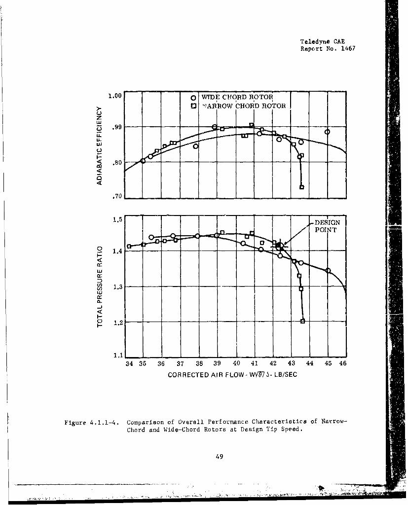
Teledyne CAEReport No. 1467
1.00 O WTDE CUORD ROTOR>.E !NI •ARROW CHiOiD ROTOli
.97U-LU-
70
1.5DESIGN
SPOINT 4Ij.. ..II . C -
o 1 ,4 1 -
X
Cr"
0~C4 1 .3 I
-J
o 1.2'
34 35 36 37 38 39 40 41 42 43 44 45 46
CORRECTED AIR FLOW- WVM-- LB/SEC
Figure 4.1.1-4. Comparison of Overall Performance Characteristics of Narrow-Chord and Wide-Chord Rotors at Design Tip Speed.
49
-- - -- - - - - - .j.'~.. ,,-"' - I. . . ' . • ,•i
Teledyne CAEReport No. 1467
The increased leading edge thickness resulted in a decrease in rotorpeak efficiency of about 3.5 points at design speed but had very littleeffect on efficiency at 90 and 70 percent design speed. Flow at designpressure ratio was reduced by about 3.0 lb/sec from 65.0 lb/sec. Theprincipal conclusion of the report was that additional loss due to in-creased thickness resulting from the bow-wave system was small compared
to the loss increase due to operation at a larger suction surface inci-dence. At design speed, the loss versus suction surface incidencefollowed the same general curve for both rotor configurations. By impli-cation then, the report indicates that through proper incidence selection,loss increases can be limited to those related to leading edge blockageand the bow-wave system, as related in Reference 11.
The attainment of design flow rate for a stago (rotor) incorporatingincreased leading edge radii would require an upscale and/or blade pro-file redefinition. Attainment of design flow through the utilizationof restagtered, open blading, would not be feasible because any flow1ncrease -,iulJ Iikely be at cnmpanied 'by even higher incidence and lossievels.
Figure 4.1.1-5 shows a generalization of the effects of leading edgeradius on rotor performancc, based on deSiug bpucd operation at peakadiabatic efficiency. The dashed lines indicated an estimate ofachievable performance with upscale and/or blade redeisgn. Use of this
data is not recommended unless absolutely necessary because correla-tion of rotor performance against blade tip geometry in this fashion isquestionable. No similar generalization of the effects on rotor per-formance of leading edge bluntness were cited by the authors of Reference1. The curves of Figure 4.1.1-5 are a linear fit of twu points. Ifapplication of the data is a necessity, it should be done only in casesof rotors having like loading levels, tip inlet relative Mach numbersand hub/tip ratios.
The results of Referenre 12, rgarding rotor trar•l•ng cdge thi-kne6,showed no adverse effects due to increased blade trailing edge thicknessto as much as 30 percent of maximum thickness for a subsonic compressorwith 65 Series blading.
4.1.1.6 Effect of Impeller Tip Clearance for a Centrifueal Stae
The effects of centrifugal compressor clearance control on efficiencyimprovement are shown in Figure 4.1.1-6.
Pressure ratio and efficiency variation with clearance, for constantsurge margin, are shown on Figure 4.1.1-7 for a typical Teledyne CAEcentrifugal stage at design corrected speed, based on the test data onFigure 4.1.1-8.
50
1W

Teledyne CAE
Report No. 1467
REF.: REID, L, & URASEK, D.C., "EXPERIMENTALEVALUATION OF T14E EFFECTS OF A BLUNTLEADING EDGE ON THE PERFORMANCE OF ATPANSONIC ROTOR," J. ENG. POWER, JULY, 1973
ad1.0-
17 ad, ref
DASHED LINES INDICATE ESTIMATESACIHIEVABLE PERFORMANCE WITH UPSCALEAND/OF BLADE REDESIGN
(PR-i)(PR-i) ref
0.9 ____
1.0!
A( p
(wca VW-8) ref
0.9.
0. 0.001 0.002 0.003 0.004 0.005
(LEADING EDGE RADIUS/CHORD) AT ROTOR TIP
Figure 4.1.1-5. Effect of Leading Edge (Radius/Chord at Rotor Tip on RotorPerformance).
51
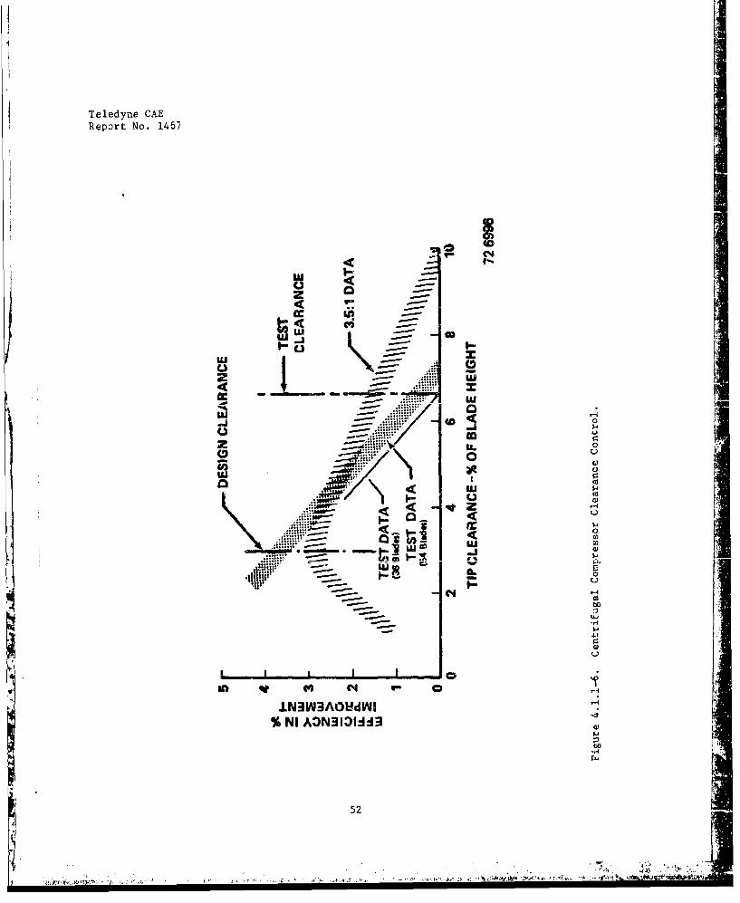
Teledyne CAE
Report No. 1467
w -j
.. ..... 0 ICD 4J
2 .4 0
C, ~ 0LLA ;4t
Co 0__4
4$4I-j
00
52'I-4

4
Teledyne CAE
Report No. 1467
100% N/ /' ; SURGE MARGIN 6.4%
-- 1.0
0.9o TEST 02 - STATIC TIP CLEARANCE = .027 in.
o1 TEST 03 - STATIC TIP CLEARANCE =.017 in.
+ DESIGN POINT
1.2
1.0 0
0.0 0.02 0.04 0.06 0.08
TIP CLEARANCE/IMPELLER TIP
PASSAGE WIDTH
Figure 4.1.1-7. Effect of Impeller 'ip Clearance/Impeller Tip Passage Width onFlow and Pressure Ratio.
53
_._._._,._. - - - - - - - - - - - - - --- - - , .- A
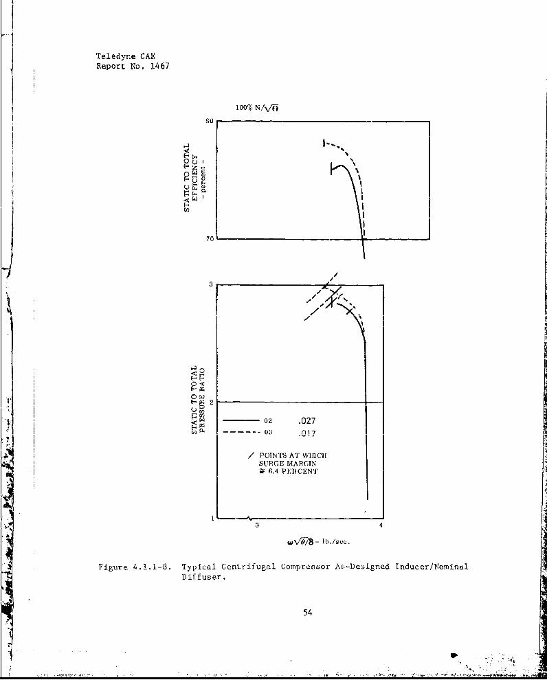
Teledyne CAEReport No. 1467
100% N/V•
OU
OH
UI
70
3
0 wK
2
oz .027
/ POINTS AT WHICH
SURGE MARGIN5 6.4 PERCENT
3 4
Figure 4.1.1-8. Typical Centrifugal Compressor As-Designed Inducer/NominalDiffuser.
54
- 0.- -.-r.-. - .t. .l:W,. •: ,.t .
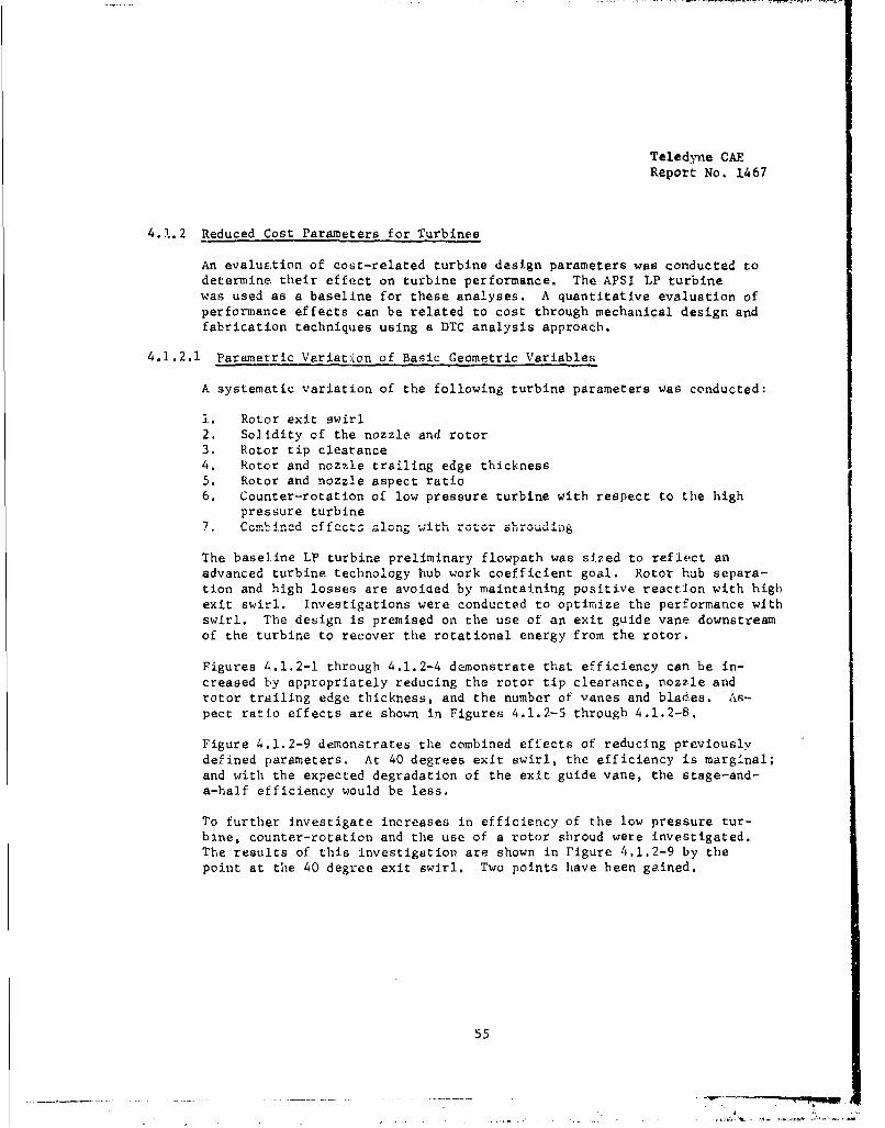
Teledyne CAEReport No. 1467
4.1.2 Reduced Cost Parameters for Turbines
An evaluation of cost-related turbine design parameters was conducted todetermine their effect on turbine performance. The APSI LP turbinewas used as a baseline for these analyses. A quantitative evaluation ofperformance effects can be related to cost through mechanical design andfabrication techniques using a DTC analysis approach.
4.1.2.1 Parametric Variation of Basic Geometric Variables
A systematic variation of the following turbine parameters was conducted:
±. Rotor exit swirl
2. Solidity of the nozzle and rotor3. Rotor tip clearance4. Rotor and nozzle trailing edge thickness5. Rotor and nozzle aspect ratio6. Counter-rotation of low pressure turbine with respect to the high
pressure turbine7. Combined effects along with rotor c..oud"ng
The baseline LP turbine preliminary flowpath was sized to reflect anadvanced turbine technology hub work coefficient goal. Rotor hub separa-tion and high losses are avoided by maintaining positive reaction with highexit swirl. Investigations were conducted to optimize the performance withswirl. The design is premised on the use of an exit guide vane downstreamof the turbine to recover the rotational energy from the rotor.
Figures 4.1.2-1 through 4.1.2-4 demonstrate that efficiency can be in-creased by appropriately reducing the rotor tip clearance, nozzle androtor trailing edge thickness, and the number of vanes and blades. As-pect ratio effects are shown in Figures 4.1.2-5 through 4.1.2-8.
Figure 4.1.2-9 demonstrates the combined effects of reducing previouslydefined parameters. At 40 degrees exit swirl, the efficiency is marginal;and with the expected degradation of the exit guide vane, the stage-and-a-half efficiency would be less.
To further investigate increases in efficiency of the low pressure tur-bine, counter-rotation and the use of a rotor shroud were investigated.The results of this investigation are shown in Figure 4.1.2-9 by thepoint at the 40 degree exit swirl. Two points have been gained.
55
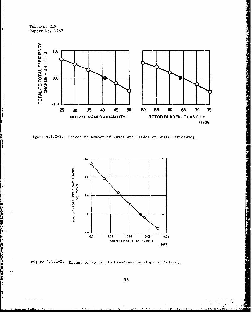
Teledyne CAEReport No. 1467
E,-'z 1-0- -'- -
- -1.0
0•= 3.0 0.0
6 z-
00
1- -1.. 1. iI--
0o
'~ -1.0
25 30 35 40 45 50 50 55 60 65 0 75
NOZZLE VANES -QUANTITY ROTOR BLADES - QUANTITY11928
Figure 4.1.2-.. Effect ot Number of Vanes and Blades on Stage Efficiency.
3.0
uDz
S 2.1)
-1,0 - -
0.0 0.01 0.02 0.03 0.04
ROTOR TIP CLEARANCE - INCH11929
Fig-ure 4.1.2-2. Effect of Rotor Tip Clearance or, Stage Efficiency.
56
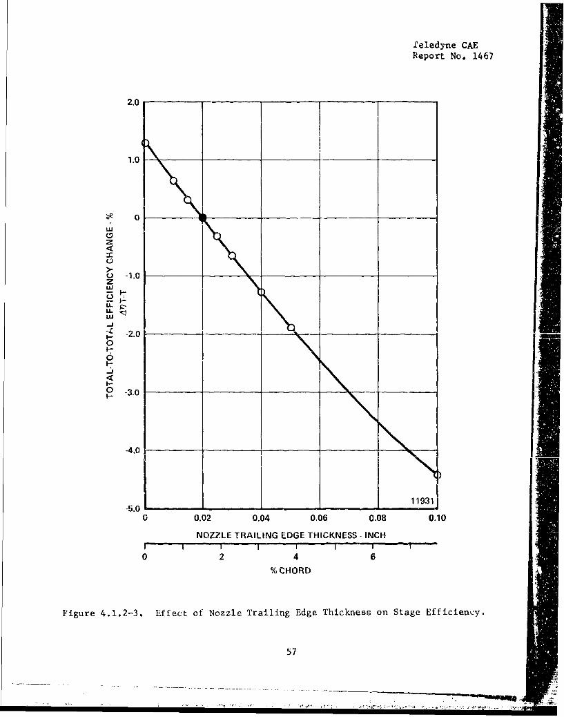
Leledyne CAEReport No. 1467
2.0
1.0
S 0 _
z
o -1.0z
I-.
w-J
- -2.001-0
-J
I-O -3.0
-4.0 -__
11931-5.0 . .
o 0.02 0.04 0.06 0.08 0.10
NOZZLE TRAILING EDGE THICKNESS - INCHI I I ' " 1 " I -
0 2 4 6
%CHORD
Figure 4.1.2-3. Effect of Nozzle Trailing Edge Thickness on Stage Efficiency.
57
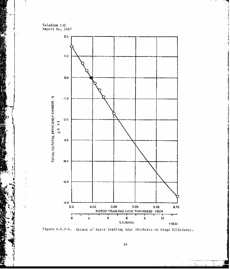
Teledyne CAEReport No. 1.467
2.0
S1.0 --
0.0 -
S-1.0w
0
F-o0- -4
_-6.0
_ 4k,.• 0.0 0.02 0.04 0.06 0.00 0.10S'• *'iRO TOR TRAILING EDGE THIICKNESS - INCH
0 2 4 6 8 10
% CHOR•D 11930
-P=, , .i•F gure 4.1,2--4 . Effect uf- Rotor Trailing Edgc. Thriknsý,6 on Stage Efficiency.
___I--- 58
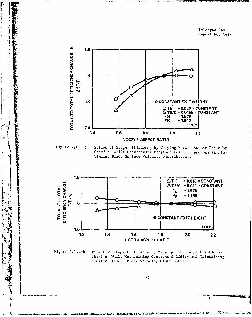
Teledyne CAEPReport No. 1467
¾. •, 1.0• LU
w3,>
0LU
It!
S-1.0 @_ - 0 CONSTANT EXIT HEIGHT
I- Z0 TE = 0.020 = CONSTANT0 A TE/C = 0.0155 = CONSTANT
ON -1.578<O 0 R -1.640t- 11934o -2.0JI-
6.4 0.6 0.8 1.0 1.2
NOZZLE ASPECT RATIOFigure 4.1.2--5. Effect of Stage Efficiency by Varying Nozzle Aspect Ratio by
Chord n- 'hilc Maintaining Coi..... .S .lidity and Maintaining
Similar Blade Surface Velocity Distribution.
1.00 T-E = 0.018.- CONSTANT
_j .0 A ATF/C - 0.021 - CONSTANT;. . = 1.578O O •OR = 1.640
S" 0!
HO
-1.0
1.2 1.4 1.6 1.8 2.0 2.2ROTOR ASPECT RATIO
Figure 4.1.2-6. Effect of Stage Efficiency by, Varying Rotor Aspect Ratio by
Chord n- While Maintaining Constant Solidity and MaintainingSimilar Blade Surface Velocity Distribution.
59
S'*
~ 'Ih~ff~AjA A -
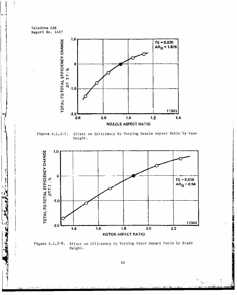
Teledyne CAEReport No. 1467
,,, 1.0- -a TE -0.020
zARR 1.878
A
z -S01
,'_j-J
o• .1.0
-.J6
0__ __-_ __ _ __ 11943
9 - -2.0•0.6 0.8 1.0 1.2 1.4
NOZZLE ASPECT RATIO
'Figure 4.1.2-7. Effect on Efficiency by Varying Nozzle Aspect Ratio by Vane
Height.
'" 1.0
° 0!
1.6 1.8 2.-2
S• TE =0.018LLAR., n .18.
ROTOR ASPECT RATIO
0 -1,0
I-02•
/ 1.4 1.6 1.8 2.0 2,2
ROTOR ASPECT RATIO
'rigure 4.1.2-8. Effect on Efficien~y by Varying R•otor Aspect Ratio by Blade
A H[eight.
60
r

Teledyne CAE
Report No. 1467
Parameter 0 0
Number of Vanes 41 31Number of Blades 64 50Nozzl, Trailing Edge ThickneM 0.020 0.015Rotor Trailing Edge Thickness 0.018 0.015Rotor Tip Clearance 0.026 0.016
4
Flasline Stage
U - -J •
2o
LA.ILU
0
0 v- 0 ..
F-
F-I.-
0 -4 -- --____ __ _ __ - __
19465
20 30 40 bOEXIT SWIRL - DEGREES
Figure 4.1,2-9. Comb.bred Effects of Hardware Changes on Efficiency ofLP Turbine.
61
Teledyne CAE-Report No. 1467
4.2 Cost Reduction Topics
The candidate cost reduction torics were obtained by a survey of allspecialized engineering and manufacturing disciplines within TeledyneCAE (including compressor design, turbine design, structvral analysis,controls and accessories, test engineering, manufacturing methods, andmaterials technology) for ideas offering cost reduction and/or perform-ance improvement. The topics thus gathered were screened by selectionprocess based on potential benefits to be derived in relation to theprobability of successful implementation. The topics selected for fur-
er investigation were:
Fan Blade Design - Effect of blade aspect ratio on total cost, weight
and performance for the same blade solidity factor.
Fan Blade Materials - Cost and weight comparison of forged and machinedtitanium blades versus forged and machined steel blades,
Cast Titanium Components - Applicability of cast titanium to variousengine components including fan blades, compressor hubs, etc., to reduceengine cost and weight.
Be-Ti Fan Power Shaft - Engine weight reduction as a result of a lightershaft and the smaller shaft diameter permitted by the lower density-higher modulus beryllium/titanium powdered metal alloy.
Brazed Axial Comnressor - Brazed assembly using titanium sheet metalblades to reduce compreusor fabrication costs.
Hybrid Radial Compresscr Diffuser - Combining both the radial and axialsections of a standard diffuser into a single cascade element; cfferscost, weight, and engine envelope advantages.
Infusionn Conlcd Vnnnri•zr Pints C:nmbhstnr - Lowering the costs of fabri-
cation by using fewer fuel injection points through more efficient fuelspreading and vaporization.
Ceramic Components - InvestigaLion of cost reductions to be obtained from
uncooled ceramic components formed to size as compared to conventionalcooled hardware for combustors and turbines.
Powdered Metal Components - Applicability of powdered metal technology tovarious engine components, particularly formed-to-finish-size turbineblades and discs.
Eliminate LP Turbine Inlet Stator - Feasibility of running contra-rotatingshafts without an inlet stator to the LP turbine stages.
62
1F

Teledyne CAE
Report No. 1467
Welded LP Turbine Assembly - Cost advantages of joining two (or more)
turbine stages by EB welding.
Jet-Flap Turbine Blading - Feasibility of extending the jet-flap conceptto the fan turbine blading,
Inter-Shaft Sealing - Elimination of the two inboard oil seals in thefront bearing cavity by providing an inter-shaft gas seal.
Gas Foil Bearings - The feasibility of replacing rolling elems-nt bear-ings and the accompanying lubrication requirements to provide costadvantages.
Simplified Lube System - Cost reductions by elirminating multiple elementscavenge puvps and using simple, high-speed rotating pumping elementswithin each bearing cavity.
High Speed Accessory Drive - Cost, weight and performance improvements
by using a reduced size drive shaft and strut through the inlet flow path.
Controls and Accessories - Reduction in cost ,nd weight of three control Iicomponents.
Engine Speaificatlon Revisions - Specification changes to reduce enginecost and weight for spccftic enrgine applications..
4.2,1 Fan Blade Design
The objective of this study was to detemnine the effect of aspect ratio
(blade height to mean chord) on the total cost and weight of a typicaltitanivm fan stage. The study analyzed designs .ising blade aspect ratiosof 1.0, 2.0, 3.0 and 4.0; each design had the seine blade solidity factor.In addition, the analysis vas repeated for fan stages geometricallyscaled by 0.707 (half-thrust size) and 1.414 (twice-thrust size). Based
r on the constant solidity factor, rhe number of blades corresponding to
each aspect ratio were determined to be:
eAspect Ratio of 1.0 - 14 bladesAspect Fatio of 2.0 - 2b bladesAspect: RAtio of 3.0 - 42 blades
Atpect Ratio of 4.0 - 56 blaides
SA generalized method for estimating the machining and material cost of atitanium blade was developed. 'The cosot factors assumed are the following:
t 63
.AW iW4 4AAT'l
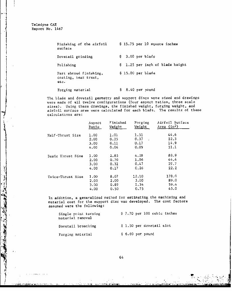
Teledyne CAEReport No. 1467
Finishing of the airfoil $ 15.75 per 10 square inches
surface
Dovetail grinding $ 3.00 per blade
Polishing $ 1.25 per inch of blade height
Part shroud finishing, $ 15.00 per bladecoating, heat treat,etc.
Forging material $ 8.40 per pound
The blade and dovetail geometry and support discs were sized and drawingswere made of all twelve configurations (four aspect ratios, three scalesizes). Using these drawings, the finished weight, forging weight, andairfoil surface area were calculated for each blade. The results of thesecalculations are:
Aspect Finished Forging Airfoil SurfaceRatio Weight Weight Area (in 2 )
Half-Thrust Size 1.00 1.01 1.51 44.62.00 0.25 0.37 22.33.00 0.11 0.17 14.94.00 0.06 0.09 11.1
Basic Thrust Size 1.00 2.85 4.28 88.92.00 0,70 1.06 44.43.00 0.32 0.47 29.74.00 0.17 0.26 22.2
Twice-Thrust Size 1.00 8.07 12.10 178.02.00 2.00 3.00 89.03.00 0.89 1.34 59.4
4.00 0.50 0.75 45.0
In addition, a generalized method for estimating the machining and
material cost for the support disc was developed. The cost factorsassumed were the following:
Single poinL turning $ 7.70 per 100 cubic inchesmaterial removal
Dovetail broaching $ 1.50 per dovetail slot
o'orging material $ 6.60 per pound
64
Teledyne CAEReport No. 1467
The cost for the various configurations of the fan blades and supportdisc for each of the twelve cases considered were calculated using thegeneralized methods described. The forging weights, finished weights,machining costs and material costs for each case are summarized inFigure 4.2.1-1.
The fan rotor weight with titanium blades versus aspect ratio has beenplotted as shown on Figure 4.2.1-2. As expected, the fan rotor weightdecreases with an increase in aspect ratio. The plot also shows, par-ticularly for the lower thrust engines, that further increases in aspectratio effect relatively minor changes in the weight of the fan rotor.The fan rotor cost versus aspect ratio plotted in Figure 4,2.1-3 showsthat there is an optimum aspect ratio for each thrust size to providea minimum actual rotor cost.
The impact of only the weight differential showed it is advisable touse the highest aspect ratio possible. Further investigation showedthat there is performance degradation which must be addressed to allowfor fabrication of the higher aspect ratio blades. A higher aspectratio blade has a shorter chord and thinner blade and requires smallerleading edge and trailing edge radii. Fabrication of the blades withsmaller radii reaches a practical limit when a minimum radius is reached.Higher aspect ratio blades can only be fabricated in small sizes by
W comprcmising leading edge radius. These blades therefore suffer a per-formance degradation which equates to an increase in specific fuel con-sumption, a detrimental system cost impact. The impact of both weightand SFC have been plotted for the different aspect ratios as they re-late to the baseline engine (Figure 4.2.1.-4), the half-thrustengine (Figure 4.2.1-5) and the twice-thrubt engine (Figure 4.2,1-6).Additional rotor costs are also affected by the use of a part-span shroudwhich is required to maintain the structural integrity of the rotor at as-pect ratios normally between 1.75 and 2.5. This is plotted in the abovereferenced curves because the actual aspect ratio where the shroud is re-quired must be determined by the specific blade configuration. Thesecurves illustrate the foliowing points:
Small engines require lower aspect ratios. (Performance degrada-tion occurs sooner and to a greater extent.)
Conversely, larger engines should use higher aspect ratios.
For any size engine, there is an optimum aspect ratio to providelowest syscem cost.
These curves can be used to identify the blade aspect ratio that pro-vides the lowest system cost; however, other considerations, such asstructural integrity, may be the determining factor in aspect ratioselection.
65
l i-4v
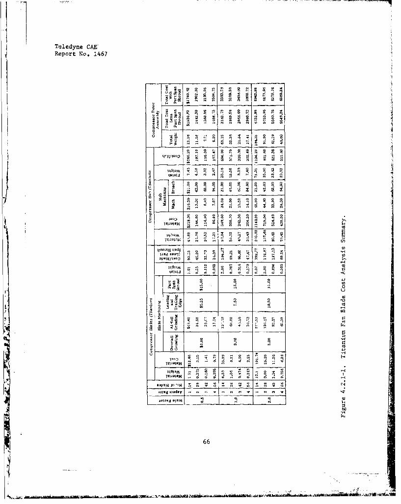
Teledyne CAE'Report No. 1467
0 4C
400a2 2 2 4 0 0
(pojl uids - C 0 - C 4*- 0
Vw Sua -lC
a 0..C C C . 0 ai 0
- - C---------
0- 04 0 N .!
04 . - C 04 0 04 4 C4
66C 0 - C C , 2 0
04 0 C .- ,7i
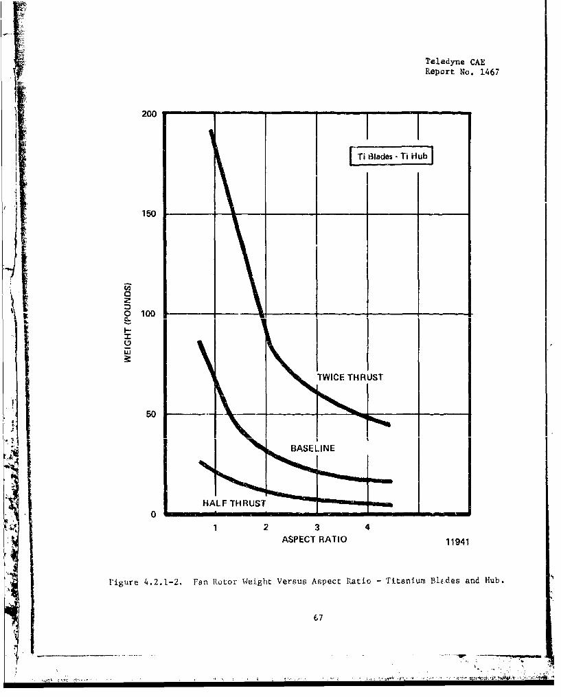
Teledyne CAE
Report No. 1467
200
150
az
w 0 100
LI
TWICE THRUST
50- _ _ _
BAEINE
HALF THRUST •
0
1 2 3 4ASPECT RATIO 11941
Figure 4.2.1-2. Fan Rotor Weight Versus Aspect Ratio - Titanium Blides and Hub.
67

Teledyne CAEReport No. 1467
8000
7000 -TWICE THRUST
' - • With Part Span
6000 Shroud I
-W/O Part Span=o • -- ,Shroud
ff5000
I 0 400I.-
Com0 4000 BASLIN =•With Part Span
- - Shroud
_ M W/O Part Span3000 Nm J = Shroud
____ ~ShroudHALF THRUST
2000 -WIO Part Span
Shroud
1000 I I I I .0 2 3 4 5
ASPECT RATIO 11927
Figire 4.2.1-3. Fan Rotor Cost Versus Aspect Ratio - Titanium Blades and Hub.
68
*1)-~ -. '4.--
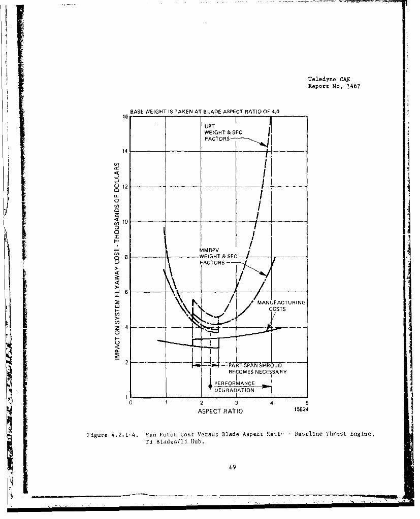
Teledyne CAEReport No. .467
BASE WEIGHT IS TAKEN AT BLADE ASPECT RATIO OF 4.0
UPTWE!GHT & SFC IFACTORS-- -,
14
012 I IiuL0
"* /U-, 1 IIz I
I-. MMRPV
o') {I WEIGHT &SC
O FACTORS> '\ 6' dor: MNFACTURING
U /COSTS
- 2 __
2 I"--- B-PART-SPAN SHROUDBECOMES NECESSARY
DEGRADATION1 1
C 1 2 3 4 5
ASPECT RATIO 1I824
Figure 4.2.1-4. 'Fan Rotor Cost Versus Blade Aspect Rati) - Baseline Thrust Engine,Ti Blades/Ti. Hub.
69
____-.!* 4. ,

Teledyne CAEReport No. 1467
BASE WEIGHT IS TAKEN Ar BLADE ASPECT RATIO OF 4.0
UPI'WEIGHT & SFCFACTORSI
U, 5__ _ _ ___ _ _ _I
cI MMRPV<1 WEIGHT & SFC
OA0 FACTORSoLL
0o Iil0 4z
S• # / #" _. MANUFACTURING
~IN
'-' BE~~COMSTNCSSR
U.
III
ASPEC/ RAI 15A8FATUIN
0,0
L)
0 2 3 4ASETRTI 52
Fiue4215Ha oo otVru ld setRto lafTrs nieTiBadsTiHb
U70
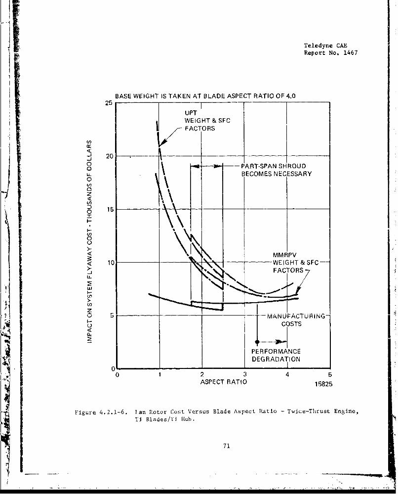
Teledyne CAEReport No. 1467
BASE WEIGHT IS TAKEN AT BLADE ASPECT RATIO OF 4.025 1
UPTWEIGHT & SFCFACT ORS
-j 20_j0o - PART-SPAN SHROUD,, BECOMES NECESSARYo
0z
0 15 x__
Nv 11 vS MMRPV
< 1C . WEIGHT & SFC---
FATORS
I-o OT
U,
'A _J
PERFORMANCE
DEGRADATION0 -
0 2 3 4 5ASPECT RATIO 15825
Figure 4.2.1-6. Ian Rotor Cost Versus Blade Aspect Ratio - Twice-Thrust Engine,Ti Blades/Ti Hub,
71
9 -•
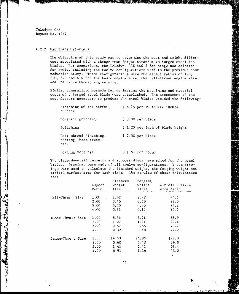
Teledyne CAEReport No. 1467
4.2.2 Fan Blade Materials
The objective of this study was to aetermine the cost and weight differ-ence associated with a change from forged titanium to forged steel fanblades. For comparison, the Teledy!', CAE 440-2 fan stage was selectedfor study, including the twelve corfigurationsa used ii the previous costreduction study. These configurations were the aspect ratios of 1.0,2.0, 3.0 and 4.0 for the basic engine size, the half-thrust engine sizeand the twice-thrust engine siie.
Similar generalized methods for estimating the machining and materialcosts of a forged steel blade were established. The assessment of thecost factors necessary to produce the steel blades yielded the following:
Finishing of the airfoil $ 6.75 per 10 square inchessurface
Dovetail grinding $ 3.00 per blade
Polishing $ 1.25 per inch of blade height
Part shroud finishing, $ 7.50 per blade
etc.
Forging material $ 1.95 per pound
Tihe blade/dovetail geometry and support discs were sized for the steelbjades. Drawings were made of all twelve configurations. These draw-ings were used to calculate the finished weight, the forging weight andairfoil surface area for each blade. The results of these rnl1culationsare:
Finished ForgingF--Aspect Weight Weight Airfoil SurfaceRatio (1ibs) (ibs) Area (in 2 )
htalf-Thrust Size 1.00 1.82 2.72 44.62.00 0.45 0.68 22.33.00 0.20 0.30 )4.9
4.00 0.11 0.17 11.1
Basic Thrust Size 1.00 5.14 7.71 88.92.00 1.27 1.91 44.4
3.00 0.57 0.85 29.74.00 0.32 0 48 22.2
Twice-Thru'iL Size 1.00 14.53 21.80 278.02.00 3.60 5.40 89.03.00 1.61 2.41 59.44.00 0.91 1.36 45.0
72
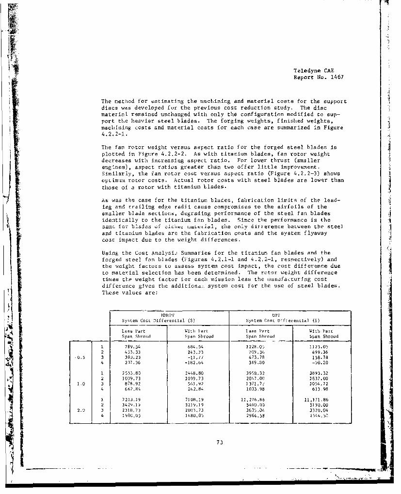
79
1 Report No. 1467
The method for estimating the machining and material costs for the support
discs was developed for the previous cost reduction study, The discmaterial remained unchanged with only the configuration modified to sup-port the heavier steel blades. The forging weights, finished weights,machining costs and material costs for each case are summarized in Figure4.2.2-1.
The fan rotor weight versus aspect ratio for the forged steel blades isplotted in Figure 4.2.2-2. As with titanium blades, fan rotor weightdecreases with increasing aspect ratio. For lower thrust (smallerengLnes), aspect ratios greater than two offer little improvement.Similarly, the fan rotor cost versus aspect ratio (Figure 4.2.2-3) showsoptimuom rotor costs. Actual rotor costs with steel blades are lower thanthose of a rotor with titanium blades.
As was the case for the titanium blades, fabrication limits of the lead-ing and trailing edge radii cause compromises to the airfoils of thesmaller blade sections, degrading performance of the steel fan bladesidentically to the titanium fan blades. Since the performance is the
OF ..... V Of uCi WLALCLtal, Lhe only difference between th steel
and titanium blades are the fabrication costs and the system flyawaycoat impact due to the weight differences.
Using the Cost Analysij Summaries for the titanium fan blades and theforged steel fan blades (Figures 4.2.1-1 and 4.2,2-I, respectively) andthe weight factors to assess system cost impact, the cost difference dueto material selection has been determined. The rotor weight differencetimes the weight factor ior each mission less the manufacturing costdifference gives the additiond:. system cost for the use of steel blades.These values are:
MMR P V U11r
System Cost Differential W$) System Cost Differential ($)
Less Part With Part tess Part With PartSpan Shroud Span Shroud Span Shroud Span Shroud
1 789.54 684.54 1228.05 1123.052 453.33 243.33 709.36 499.36
-0.5 3 303.23 -11.1/7 473.78 158.784 237,36 -182.t4 369.30 -50.20
1 2553.80 2448.80 3998.32 3893.322 1039.73 1099.73 2047.00 3837.00
1.0 3 878.92 561.92 1371.71 1054.724 662.84 242.84 1033.98 613.98
1 7213.19 7108.29 11,276.86 11,171.862 3429.19 3219.19 5400.00 5190.00
2.0 3 2318,73 2003.73 3635.04 3320.04
1900,05 1480.05 2964.58 2544,>,
73
L,....l.. _ _ _ _ _ _ _ _ _ _ _ _ _-.4
! !nww

""V+---r 1 . . r+l• i~
Teledyne CAEReport No. 1467
S-i • '' - • " Li -• " -
0 N Li 0 0 , , -0 . .L.
qnlelsll/ j ) L
I -.I: ...
.IIICi
4. _____ - - £
99a 0ý 0 0 0 0
U)
4J
lop 0j 0j~ Li 0 . U U U - L
74 i N Li N L U i 4
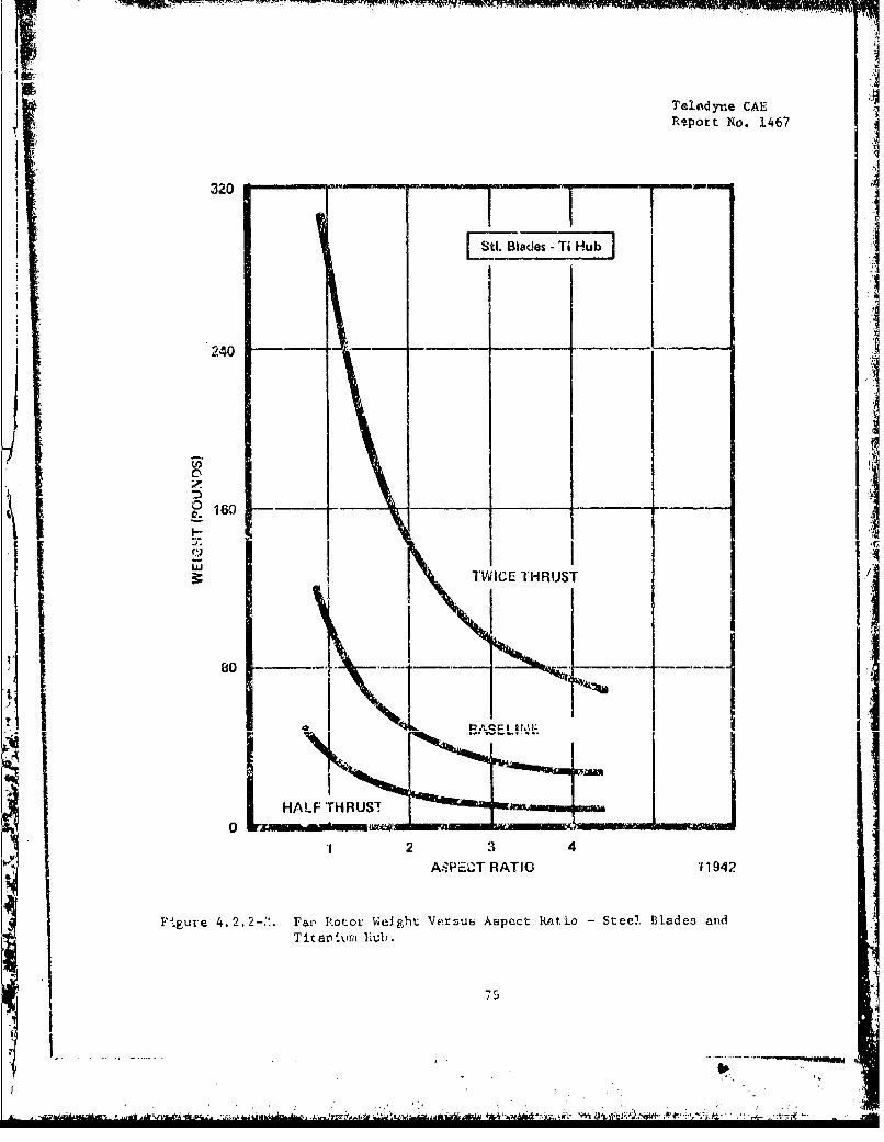
Teledyne CAEReport No. 1467
320liii1
St.Blades -Ti1u~b]
1 V ~240 -
TWJICE THRUST
1' ~~~~80 -*-' -
HALF rHRUSI
I2 34AVEc"..T RATIO '11942
Fl-.gure 4.22-".~ rea Roto Weight. Versus Aspect Ratko -Steel. Blades andTitanivni hub.
75'
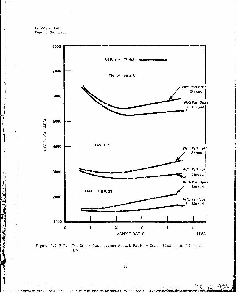
Teledyne CAEReport No. 1467
8000
Stl Blades - Ti Hub
7000TWICE THRUST
With Part Span
6000 -Shroud
",WIO Part Span
SShroud
Z 5000cc
-J
0
I-o 4000 BASELINE
With Part Span
Shroud
3000_ WVV/0 Part Span3000 •Shroud
With Part Span
HALF THRUST
.2000 •W/O Part Span
10Shroud
100S0 12 3 45
ASPECT RATIO 11927
Figure 4.2.2-3. Fan Rotor Cost Versus Aspect Ratio - Steel Blades and TitaniumHub.
76
44i

h:' - : rj . - - • ' -. . 'U- ='nrurir 'r-- •:•• ••• <=•• ::;•: ? ,i
Teledyne CAE
Report No. 1467
As shown, .!-.ere art; only three inrtancees where the eteel blades have lesssystem cost than the titsnium b.adea, These aLe for the small, high aspectratio blades, rerreven-ed In the table by the negative values. Aspecc:.at.Los nmoot be selected with caubicn lL.cautte of the severze performanceelegc'adation frequen•tly lncuirred 6)th~ bladee,
4.2,3 Cast Tican.aind omponents.
The objective of %his study was to evalzate the cost and weight savingsasscriated with using cast titanium otigih-E compnnents. The fan and com-pre&sor rotating confpoi•t.t -were uelected a.s the most probale candidatesto benerit from the propcsed material &nd fabrication substituLionX La-cause of their high manufacturing costs and low temperature operatingSenvirunment. The advantages of using titanium alloys in these componentsare confirmed by ?-a'eious results and comparisor of Ti-6-4 all.oy'a strength,weight and temperature capaLility Lo other currently used conpressoralloys.
Conventional forgpd/machined fan and axial compressor rotors require*1tnsv -,,rprlinn wmor
1,inn,gr to obtair. 1b a,o f_ ol' perh annt~d closc
tolerances resulting in costly hardware. By the use of invectn;ant casttitanium and integral bladed rotors, signfticaAt cost savings can berealized for both components. Additional weighs suings for the ax.lalrotor are possible because of the lcoer density of titanium compared tothe current casting material, 17-4PU steel.
The justification for recommending cast titanium for these criticalrotating ,oaponents is based on the caqting program conducted atTeledyne CAL on an axial compreesor rotor anJ an axial compressorb)ade. These programs used 6AI-4V titanium alloy and demoistratedrh .- capabiltty of filling thin airfoil sections (0.008 to 0.012inch leading and trailing edge thicknesV). The airfoils were cast
slghl cvrsz, cLLiWýIIQIiJtty IL..t.~LUbhe*LlrtSiig
surfaces and airfoil radii were suitable for eng ine ea-odynamic evalu-ation. In addition, the benefits of hot isostatic prasing (HIP) waredemonstrated as a means of removing ehrir.kage defects from the airfoil.Material properties testing up to 800'r indicated t-v suitability of
these cast parts for rig and engine testing. The goon ductility of 8percent at room temperature was particularly signifi:int. A compari-son of data for wrought and cast HIP'ed titanium is hown in Figure4.2.3-1. Although the cast material has slightly lower strength, arotor burst iargin of 1.23 ie provieed by the minimum properties of11,002 psi tensile strength and 100,000 pai yiE-d strength, deter-mined from tist specimens removed from sample castings.
The. structural integrity of this comple:, Intagrally bladed cast titaniumrotor was demonstrate.d by a successful spin test to 110 percent of enginemechanical speed. The cast rotor is shown in Figure 4.2.3-2. The appli-cation of ca.t titanium •as cuccess,'u.ly demcnmtrated for zhe individualccmnn:. ensor blades as illustc'ated iA Figai.o 4.2.3-3. These blades, of
77
-W1
j I 4~ . - > I, -t,. 41 ~(~~'4 $~'fl,~4
44 ,' f-~., -Ave'rt ~
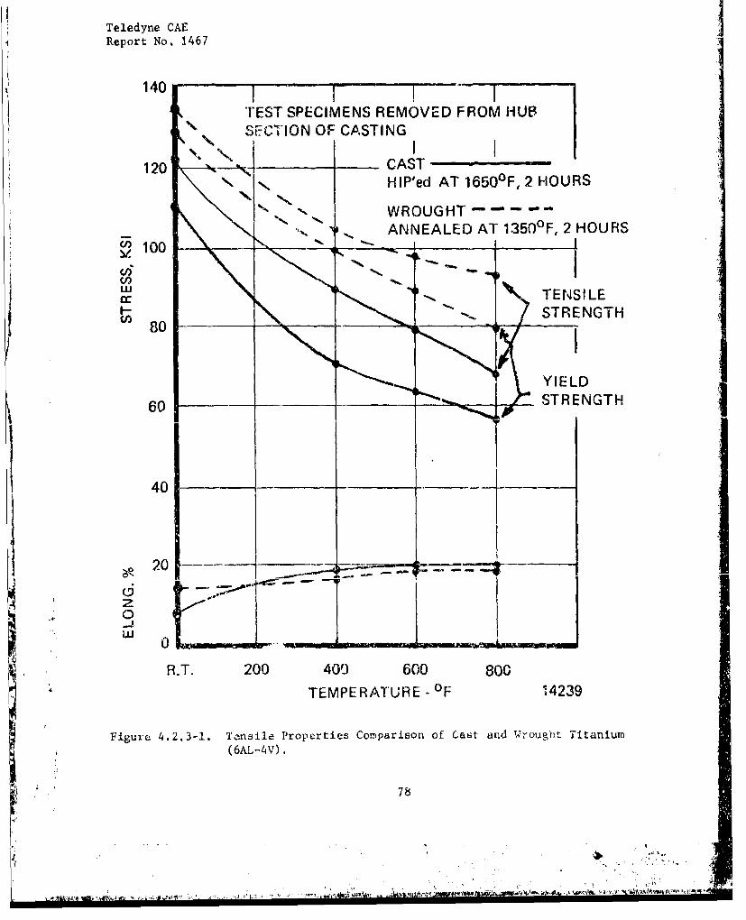
Teledyne CAEjReport No. 1467
140----
TrEST SPECIMENS REMOVED FROM HUBSti'C"ION OF CASTING
120 - -- ~- C SHIP'ed AT 16500F, 2 HOURS
WROUGHT~V ANNEALED AT 1350OF, 2 HOURS
w ~TENSI LEa-
80
YIELD
60 STRENGTH
20
* 0 0
* UU
R.T. 20 49 600 800
TEMPERATURE - OF4239
Figure 4.2.3-1. Tansile Properties comparison of Cast and Wrought Titanium(6AL-4V).
78
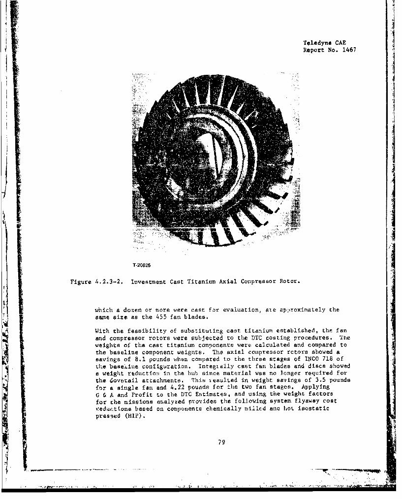
Report No. 1467
4ý4
II
T-20825
Figure 4.2.3-2. Investment Cast Titanium Axial Compressor Rotor.
which a dozen or more were cast for evaluation, are approximately thesame size as the 455 fan blades.
With the feasibility of substituting cast titanium established, the fanand compressor rotors were subjected to the DTC costing procedures. Theweights of the cast titanium components were calculated and compared tothe baseline comnponent weights. The axial compr-essor rotors showed a
savings of 8.1 pounds when compared to the three stages of INCO 718 ofthe base.ine configuration. Integially cast fan blades and discs showeda weight reduction in the hub since material was no longer required forthe dovetail attachments. This iesulted in weight savings of 3.5 poundsfor a single fan and 4.22 pounds for the two fan stages. ApplyingG & A and Profit to the DTC Estimates, and using the weight factorsfor the missions nnalyzed provides the following system flyaway cost):eductions based on compunents chemically milled anc hot isostaticpreseed (HIP).
79
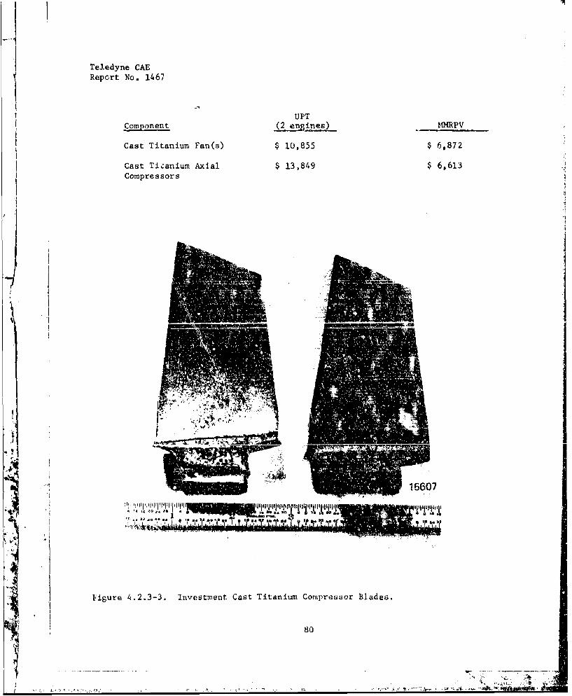
Teledyne CAEReport No. 1467
U PT~nent S nes) I4MPV
Cast Titanium Fan(s) $ 10,855 $ 6,872
Cast Ticanium Axial $ 13,849 $ 6,613 I
Compressors
_A
15607
Figure 4.2.3-3. Investmnent Cast Titanium Comipress~or T$1adeG.
80-
Teledyne CAEReport No. 1467
4.2.4 Beryllium/Titanium Fan Power Shaft
The objective of this study was to determine the impact on engine costand weight by using a beryllium/titanium alloy fan power shaft. Beryllium/titanium composites have excellent stiffness-to-weight ratios which en-courage weight reduction studies. A Be/Ti composite of 70 percentberyllium (by volume) was selected to obtain an optimum stiffness-to-weight ratio for shafts. The volume percents chosen give a density of0.0913 lb/in 3 and a Young's Modulus of 33.6 million psi. A preliminarydesign of a two-stage titanium fan and a two-stage steel power turbinewas analyzed for shaft critical speeds and natural frequencies utilizing Tele-dyne CAE's Computer Program 02.074, the "Critical Speed Multiple-Shaft System".Shafts with varying diameters were evaluated to determine the minimumshaft size and resulting passage through the gas generator. The smalleý:tshaft analyzed (1.4 inch outside diameter) has a free-mode criticalspeed of 33,837 rpm, providing a margin of greater than 50 percent onthe low pressure shaft speed. The natural frequency of the same shaftcomputed at 22,000 rpm equals 41,182 rpm for a support stiffness of 106
lbs/in. Figure 4.2.4-1 is a plot of frequencies versus support springrates for the recommended sbaft. The natural frequencies of the shaftcan be altered to avoid resonant conditions during detail design byJudCc...U. selt..i•ui of she bearing support stittnesses. Figure 4.2.4-1shows that the 1.4 inch outside diameter shaft will have a margin onbending frequency of 10 percent with the high pressure shaft speedwith both bearing spring rates equal to 640,000 lbs/in.
The preliminary analysis indicates the feasibility of obtaining satis-
factory dynamic performance using a beryllium/titanl- composite shaft.With this basic assumption, the engine componeots were redesigned
to realize the greatest advantage possible by using a smaller dia-meter shaft. The gas generator discs were analyzed with the borediameters decreased by 0.8 inch and the cross-sections recontouredto provide identical burst margins to the current design.
The proposed Be/Ti composite is basically a product of powder metallurgy
extrusion. The fabrication techniques involved are relatively uncompli-cated. Beryllium and titanium powders are mixed together, canned in ajacket, and extruded. The extrusion process converts the beryllium andtitanium powders into micro fibers which are diffusion-bonded under theinfluence of the extrusion temperature and pressure. Metallurgicalexamination has shown that excellent diifusion bonds, devoid of majorconcentrations of titanium beryllide reaction products, are the resultof this process.
The composite is easily produced with a monolithic titanium alloy surfaca"skin" which is desirable for the iiachining of threads and splines onthe external surface. This composition is shown in Figure 4.2.4-2, andthe canning process is pre ated in Figure 4.2.4-3. The latter figure
represents the method whi L. would be used to provide a Be/Ti shaft with
S i 81
t ' _
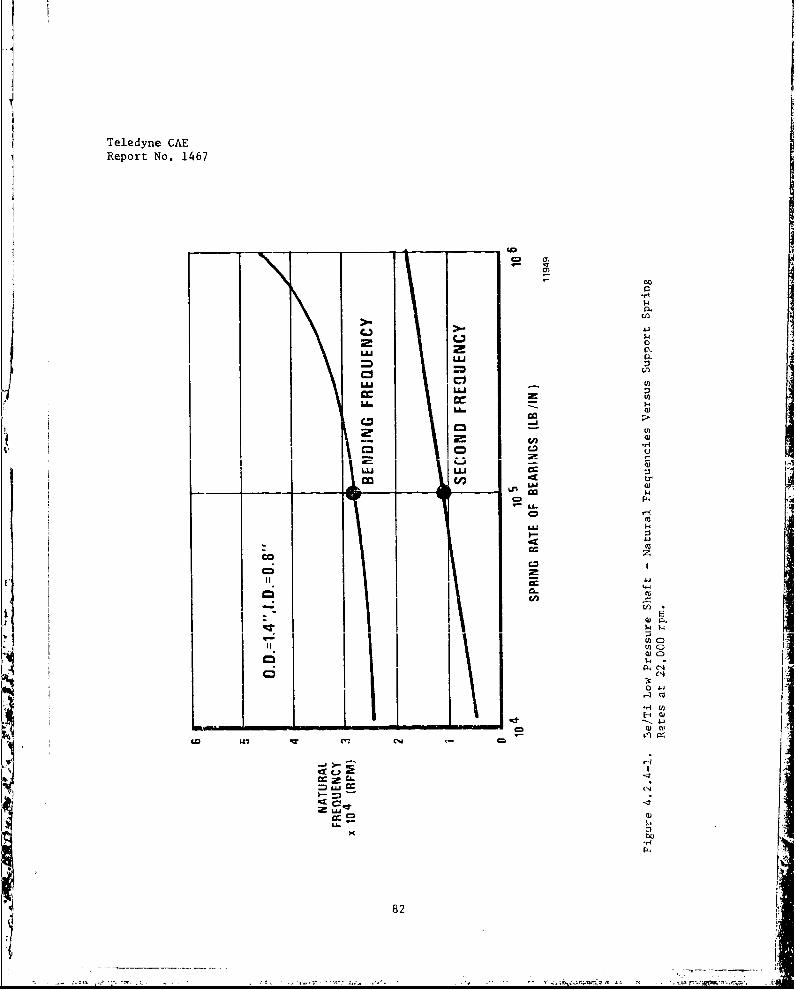
Teledyne CAEReport No. 1467
- k
CD
uCl.
LUU
LU-
LU LLIC
co 141
LA-
CD
III 01 11-L"/00
Cm'C
C&
82
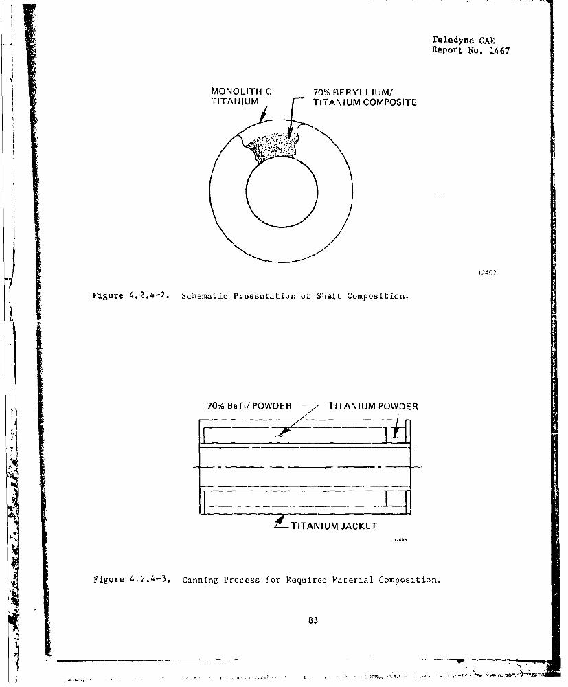
Teledyne CAE
Report No. 1467
MONOLITHIC 70% BERYLLIUM/"TITANIUM TITANIUM COMPOSITE
7 .J
I 12497
Figure 4.2.4-2. Schematic Presentation of Shaft Composition.
70% BeTi/POWDER -- TITANIUM POWDER
4' . I
nd--TITANIUM JACKET
1249b
Figure 4.2.4-3. Canning Process for Required Material Composition.
83
7 ~ ~ ~ ~ ~ ~ ~ ~ ~ ~~~- t4-.......................
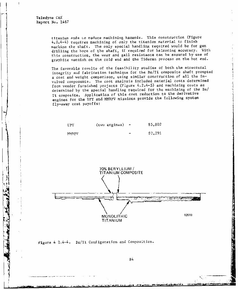
Teledyne CAEReport No. 1467
titanium ends to reduce machining hazards. This construction (Figure
4.2.4-4) requires machining of only the titanium material to finish
machine the shaft. The only special handling required would be for gun
drilling the bore of the shaft, if required for balancing accuracy. With
this construction, the wear and gall resistance can be assured by use of
graphite varnish on the cold end and the Tiduran process on the hot end.
The favorable results of the feasibility studies of both the structural
integrity and fabrication technique for the Be/Ti composite shaft prompted
a cost and weight comparison, using similar construction of all the in-
volved components. The cost analysis included material costs determined
from vendor furnished projects (Figure 4.2.4-5) and machining costs as
determined by the special handling required for the machining of the Be/
Ti composite. Application of this cost reduction to the derivative
engines for the UPT and NMRPV missions provide the following system
fly-away cost payoffs:
UPT (two engines) - $5,802
bMRPV $2,291
70% BERYLLIUM /
TITANIUM COMPOSITE
-71
MONOLITHIC 12510
TITANIUM
figure 4 2.4-4. Be/Ti Configuration and Composition.
84
.......... Aire"1-

Teledyne CAEReport No. 1467
= 0LUO
aC!
uJ
I.-
• 02
rb
cn5
CD c,
CD 0
CDU
C2U
Ln CII4ý
85
-- - -- -
iN
Teledyne CAEReport No. 1467
4.2.5 Brazed Axial Compresssor
The objective of this study was to reduce costs by using formed-to-finishsize titanium axial compressor blades brazed into a one-piece drumstructure.
The concept of brazing finished titanium compressor blades on the axialcomor.sssor discs has been presented in a preliminary design layout (Figure4.2.5-1). A drawing of the first stage blade (Figure 4.2.5-2) was madeto determine the structural feasibility, manufacturing the airfoil shapesfinished to size in titanium and to determine the resultant tolerances
for each of the manufacturing processes. The procesues considered were
jrecision forgings, precision castings, and powder metal consolidation.Our present machined tolerances can provide contour tolerance bands of
plus or minus two thousandths of an inch. The precision cast blades,chemically milled to remove the alpha case, along with the powder metalifabrication, can provide the same contour tolerance bands. The preci-sion forged blades can provide contour tolerance bands of plus or minusthree thousandths of an inch. The aerodynamic perfoermance variation dueto such a minuscule ailerance deviation is not within the limits ofpractical determination and is considered minimal. In actual practice,the normal tolerance distribution would never provide the extremes of
the contour tolerance band. For this reason, all of the manufacturingprocesses were considered to provide equivalent aerodynamic performavce.
The foregoing tolerance determination provided the basis for establishingthe feasibility of brazing the titanium blades onto the drum. With theairfoil contour tolerance set at plus or minus 0.003 inch and the punchedairfoil contours _n the rings at tolerances of plus or minus 0.002 inch,the brazing gap will be from line to line to 0.014 inch maximum. Con-tacts were established with vendors ex.perienced in titanium brazing andwith braze alloy sources to confirm the brazing capability using our com-ponents. Once the surface contamination of titanium is overcome to affordgood wetting, titanium is easily brazed. There are many braze alloysavailable for titanium brazing. However, to maintain good ductility and
wide gap capability, an alloy such as AMDRY 692 should be utilized. Thisis a silver. palladiuw-aluminum alloy which uses the palladium to form aphase barrier against the diffusion of titanium and silver. AMDRY 692braze alloy has high ductility and wide gap (up to '.030 inch) brazing
41 capability, It is also a low temperature brazing alloy from 1500°F to1550'F and has a shear strength of 35,000 psi.
The manufacturing concept describer- above is feasible; however, sample braze
joints shcvld be evaluatee to confirm strength characteristics.
A preliminary structural analysis was conducted on the proposed d'sign.Thu blade stresses, previously calculated for both cast 17-4 steel and1I40 718 alloy, were not calculated because the strength-to-density ratioof titan-um is greater than thc steels, thereby providing greater safetymargin than the present design.
¶ N 86
•~i -

VTeledyne CAE
Report No. 1467
ELI WELD
L Figure 4.2.5-1. Preliminary Design Layout of Three-Stage Axiel Rotor.
S 1 A C K IN U UL l lt-.
'I ' AK 1( OI '
11922
Figure 4.2.5-2, Rotor Blade.
87

4JTeledyne CAEReport No. 1467
The analysis focused on the blade attachment stresses based on the assump-tion that all of the braze area shares the blade centrifugal load. Infact, the braze in the sheet metal ring carries the load until it yieldsenough to permit the remaining areas to pick up a share. The interactionbetween the brazes in the sheet metal ring and in the disc should also be
investigated thoroughly during the design and evaluation program.
The gas loadings were reacted by the braze in the sheet metal ring. Anequivalent moment of inertia using the braze shear area was calculated at0.000636 in 4 about the minimum axis, and 0.02035 in 4 about the maximumaxis. A r~ng thickness of 0.050 inch was used. The resultant calculatedgas "ending braze stress is 2032 psi.
Figure 4.2.5-3 gives a sumnary of the blade attachment stresses. The com-bined stress of 10,182 psi considers 100 percent of the braze area to beeffective, Btaze is rarely 100 percent effect.ve and the allowable stresswill not be known until the brazing alloy has been evaluated. However,based on the 10,182 psi stress, a safety factor of 1.47 can be achieved
with only 50 percext braze effectivity, if the braze material allowablestress is on the orcer of 30,000 psi.
±uajI nxu L v braze (in-) 0.30371
Blade pull (titanium, 100% Speed) (lb) = 2475
Stress P/A (psi) = 8150 (for equal load sharing throughout)
Gas bending moments (in/lb) tangential = 6.33
(in/lb) axial = 4.15
Equivalent moment of inertia in sheer of the braze in the
-0---at&!0.00 in tniei•)
Minimum axis (in4) =0.000636
Maximum axis (.'n4) 0.02035
Assuming braze in sleeve resists all gas bending loads.
Stress (shear in braze at trailing ýdge) (psi) = 2032
Total stress in brazed joint (psi) ý 2032 + 8150 = 10.182
Figure 4.2.5-3. Stress Summary - Brazed First Stage Blade on Ring Disc.
* 88 • i•
6 " ½r
Teledyne CAEReport No. 1467
The rotor uirum was analyzed to determine the maximum bore stresses of therings comprising the three axial scages of the compressor. These stresses,summarized below as percentages of yield for comparison between thetitanium rotor and the individial 11100 718 discs, are significantly lowerthan those of the current disc design.
Titanium L.,,tor INCO 718 Discs
Bore Stress % of Yield Bore Stress % of Yield
(psi) _-(psi)
First Stage 80,000 69 112,000 76Second Stage 69,000 69 104,000 72Third Stage 60,500 69 107,000 75
The preliminary analysis shows that the brazed axial compressor concept isviable in terms of structural inte!grity.
A design layout was made which er. :ompasses the mechanical designfeatures selected to contribuze :, the cost reduction of the axialcompressor section. One such fez&tare is the one-piece drum construction,fabricated by EB welding the tut'•rnally finished rings together. Thisrotor can subsequently be fin tsl- n.achined by crush-grinding the externaldiameters to provide close tolerýance dimensions for the brazing surfacesand flowpath wall through ure of a rapid, low cost material removalmethod. A comparison with Lsc ilaseline engine configurationshows that it is possible to el½winate the compressor labyrinthseals and inner stator rings by cantilevering the stator vanes. Recircu-lation leakage is eliminatad ix. two stages, and the rotating inner flow-path wall tends co elimin;ite vortices in the end wall stall region whichare common to stators of Lxi.< type. In addition, the one-piece rotorassembly requires less balanicing and assembly time than the individual"rotors and seals because ane integral three-stage rotor only needs to
be calibrated once on the balancing equipment, while the individual rotorsmust be calibrated three times.
Costs were estimated for the integral drum rotor compressor using the
DTC costing procedures, and then compared to the baseline configuration.The weight of this configuration, when compared to the baseline weight,showed a savings of 8.48 pounds. Applying G & A and Profit to the DTCEstimates, and using the weight factors established from mis3ion analy-ses, yields the following system cost reductions:
UPT (two engines) - $9,350
RPV - $4,349
These subc-antial savings are not as great as those fromi cast titanium"T axial compressors ($33,849 and $6,613, respectively) but are certainly
worthy of consideration as alternatives.
89
I ........_
......

Sw '• ww: r r ri • .- -... . - *. .. W w~--+ j, -.•' w-u•~.~ w ~ y
K
Teledyne CAEReport No. 1467
4.2.6 Hybrid Radial Compressor Diffuser
The objective of this study was to reduce the manufacturing cost andimprove performance of the radial compressor diffuser by using a singlemixed-flow diffuser instead of the separate radial and axial diffuserstator rows. The proposed mixed-flow diffuser was designed to therequirements of the baseline engine. The configuration providesa continuous diffusing channel from inlet to exit. The area distribu-tion differs from that presently employed in the diffuser for thebaseline engine, which has a radial diffuser coupled by a con-stant area elbow to an axial diffuser.
A cost analyses of the hybrid radial diffuser was made and compared tobaseline configuration (radial and axial diffusers). The cost analysesS~for both types of diffusers were performed using the same fabrication
criteria. Processes and machining were identical where the diffusershad common features, allowing the comparison to reflect the true costdifferential due to the elimination of the attendant machining require-ments for one pait.
The hybrid radial diffuser cost estimate was coiapared to the baselineengine costs, and then G & A and Profit were applied to the difference. 4
The one percent improvement in SFC was expressed in lbs/hr/lb for eachof the engines used in the UPT and MMRPV missions, and the respectivevalues of SFC in airframe flyaway cost were applied. The system fly-away cost reductions are in order of 1 - 6 thousand dollars, dependingon the complexity of the aircraft of interest.
4.2.7 Infusion Cooled Vaporizer Plate Combustor
The objective of this study was to reduce the cost of the baseline engine com-bustor by eliminatiihg fuel nozzles, film cool±ng strips, corrugatedstrips, and numerous machined holes for distribution of air flow,The chamber liner is fahriarptd frnm porous sintered wire mesh toprovide a controllable film for infusion cooling. The injectionSsystem is annular, thus eliminating numerous parts associated withthe fuel vaporizer pipes.
Three-layer Rigimesh, 12 x 64 mesh, is specified for the liner becausethe airflow pressure drop characteristics are appropriate for this appli-cation. A + 12.5 percent tolerance band on the nominal airflow of 40scfm/ft 2 , established to minimize processing costs, results in the averageliner metal temperature variation shown in Figure 4.2.7-1. Since the
901
1 . .1

Teledyne CAEReport No. 1467
liner pressure loading is minimal (7 psi AP at design point), otherstructural considerations and/or oxidation resistance versus required lifewill govern the range of allowable metal temperature and the selection ofthe Rigimesh type base material.
t The vaporizer plate effective flow area, sized to provide the combustion
IV air required at design point, eliminates the need for auxiliary baseplateholes and associated life problems, thus minimizing fabrication and systemoperational costs.
The vaporizer plate length, determined by a heat balance across the sur-face area of the plate, was arbitrarily reduced by 25 percent to accountfor fuel film turbulence and wave interaction with the primary combus ionair. These secondary effects are difficult to accurately consider in theheat balance, but would enhance the heat input to the fuel. The vaporizerplate length and the degree of vaporization at various operating condi- j
tions and locacions will be verified by test.
The infusion cooled vaporizer combustor provides the potential for remov-
ing the axial diffuser vanes from the radial compressor diffuser. The
infusion cooled liner readily accommodates the residual swirl in the airentering thp combxistor. The residual swirl will be advantageous entering
the HP turbine inlet nozzle, allowing at least 10 percent of the turbine
inlet nozzle vanes to be removed. The increased pressure loss of the
swirling air entering the combustor is offset by the decreased pressure
loss caused by removing the axial diffuser. The total effect on the engine
is to maintain the same level of performance with fewer parts.A
A detailed cost analysis was performed to determine the comparative cost
of the infusion cooled vaporizer plate combustor with the baseline engineconfiguration. This cost comparison is summarized in Figure 4.2.7-2.As expected, elimination of the fuel nozzles and the cooling strips, andthe multInlicitv of holes in the combustor liners drastically lowers the
I 'number of labor hours required for manufacturing. Although the materialcost increases by over $1700 for all items (primarily because of the pre-formed porous material), the total savings attributed to this configura-tion when C & A and Profit are applied to the costs is $3,776.00. Addi-
tionally, there is a weight reducticn of 5.4 pounds for the proposed con-figuration. When the mission-established weighting factors are applied,the system flyaway cost reductions are:
UPT (two engines) - $8,778
MMRPV $4,181
91
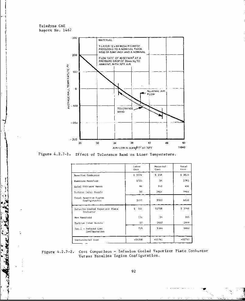
Teledyne CAEReport No. 1467
301MATERIAL
3 LAYER 12 x64 MESH RIGIMESHPROCESSED TO A NOMINAL THICK-NESS OF 0.047 INCH AND A NOMINAL
FLOW RAlE OF 40 SCFM/ft2
AT APRESSURE DROP OF 30mm Hg TO
AMBIENT, WITH 700
F AIR.
m 100 --
IQ.
0
<N
> --100
• -20u
+t --200
26 30 34 38 42 46 50
AIRFLOW IN SCF/F4T' AT 700
F 11940
Figure 4.2.7-1. Effect of Tolerance Band on Liner Temperature.
Labor Material Total
Cost Cost Cost
Baseline Combustor $ 3374 $ 259 $363
Baseline Manifold 1725 58 1783
Axi I Diffuser Vanes 98 352 450
Total-Baseline EsgIne
.Conftguration 5227 3583 I8ll
Infusion.Cooled Vaporizer Plate 541 $2708 $ 3249
Co buVtor
New ManIfold 151 14 165
Turbine Inlet Nozzle 27 2622 2649
Tot-,1 - Reduced Cost 719 5344 6063Conf i•urat ion
if ferentlal Coat -$4508 +f1761 -$2747
Figure 4.2.7-2. Cost Comparison - Infusion Cooled Vaporizer Plate CombustorVersus Baseline Engine Configuration.
92
S...... . .. •- • .•
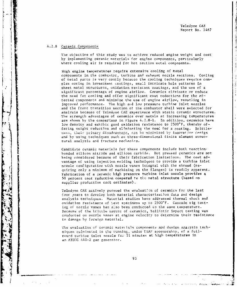
Teledyne CAE
Report No. 1467
4.2.8 Ceramic Components
The objective of this study was to achieve reduced engine weight and cost
by implementing ceramic materials for engine components, particularly
where cooling air is required for hot section metal components.
High engine temperatures require extensive cooling of metal
components in the combustor, turbine and exhaust nozzle sections. Coolingof metal parts is very costly because the cooling techniques require com-
i Lplex coring in investment castings, small intricate hole patterns inI sheet metal structures, oxidation resistant coatings, and the use of a
significant percentage of engine airflow. Ceramics eliminate or reducethe need for cooling and offer significant cost reductions for the af-
fected components and minimize the use of engine airflow, resutling in
improved performance. The high aid low pressure turbine Inlet nozzles
and the front transition section of the combustor shell were selected for
analysis because of Teledyne CAE experience with static ceramic structures.The strength advantages of ceramics over metals at increasing temperaturesare shown by the comparison in Figure 4.2.8-1. In addition, ceramics have
low density and exhibic good oxidation resistance to 25000 F, thereby of-
fering weight reduction and eliminating the need for a coating. Brittle-
nss, th-Le i r prJim L-a r y i .sadvan tag, car mrn z by innovative designand by using techniques such as three-dimensional finite element struc-I tural analysis and fracture mechanics.
I iCandidate ceramic materials for these components include both reaction-
bonded silicon nitride and silicon carbide. Hot pressed ceramics are notbeing considered because of their fabrication limitations. The cost ad-vantage of using injectton molding techniques to provide a turbine inletnozzle configuration with nozzle vanes integral with the shroud (re-
quiring only a minimum of machining on the flanges) is readily apparent.
Fabrication of a ceramic high pressure turbine inlet nozzle provides a50 percent cost reduction compared to t ne metal structure (based on
Teledyne CAE actively pursued the evaluat!sn of ceramics for the lastfour years to develop both material characterization data and design
A analysis techniques. Material studies have addressed thermal shock andoxidation resistance of test specimens up to 2500°F. Cascade rig test-ing of nozzle vanes has also been conducted to the same temperature.Because of the brittle nature of ceramics, ballistic impact testing was
conducted on nozzle vanes at engine velocity to determine their resistanceto damage by foreign material.
The evaluation of ceramic mateiials components and design analysis tech-
niques culminated in the running, under USAF sponsorship, of a full-
rourd turbine inlet nozzle fo-z 51 minutes at high temperatures inan ATECO 440-2 gas generator.
93
n -- :-- - . - - - - - - - - - *-- .

I.-.
Report_ Noq16
Teledyne CAEReport No. 1467 i
OF
392 752 1112 1472 1832 2192 2552140 - -
120 NICKEL BASE- __ALLOYS
801O 1 11l-,:= 80 ,, _
b t9 ___VIz 6060Uj REACTION BONDED40
Si3 N4
20 _ •
RT 200 600 1000 1400
TEMP.°F 15581
Figure 4.2.8-1. Strength Comparison of Ceramics (Si 3 N4 ) and Suveralloys.
94
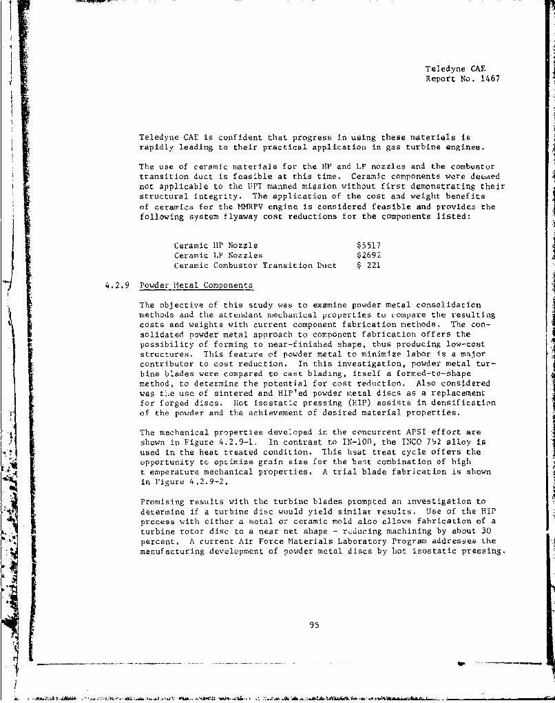
Teledyne CAEReport No. 1467
Teledyne CAE is confident that progress in using these materials israpidly leading to their practical application in gas turbine engines.
The use of ceramic materials for the HP and LP nozzles and the combustortransition duct is feasible at this time. Ceramic components were denednot applicable to the UPT manned mission without first demonstrating theirstructural integrity. The application of the cost and weight benefitsof ceramics for the MMRPV engine is considered feasible and provides thefollowing system flyaway cost reductions for the components listed:
Ceramic HP Nozzle $5517Ceramic LP Nozzles $2692Ceramic Combustor Transition Duct $ 221
4.2.9 Powder Metal Components
The objective of this study was to examine powder metal consolidationmethods and the attendant mechanical properties to compare the resultingcosts and weights with current component fabrication methods. The con-solidated powder metal approach to component fabrication offers thepossibility of forming to near-finished shape, thus producing low-coststructures. This feature of powder metal to minimize labor is a majorcontributor to cost reduction. In this investigation, powder metal tur-bine blades were compared to cast blading, itself a formed-to-shapemethod, to determine the potential for cost rediction. Also consideredwas tl.e use of sintered and HIP'ed powder maetal discs as a replacementfor forged discs. hot isostatic pressing (HIP) assists in densificationof the powder and the achievement of desired material properties.
The mechanical properties developed in the concurrent APSI effort areshown in Figure 4.2.9-1. In contrast to IN-O00, the INCO 792 alloy isused in the heat treated condition. This heat treat cycle offers theopportunity to optimize grain size for the best combination of hight emperature mechanical properties. A trial blade fabrication is shownin Figure 4.2.9-2.
Promising results with the turbine blades prompted an investigation todetermine if a turbine disc would yield similar results. Use of the HIPprocess with either a metal or ceramic mold also allows fabrication of aturbine rotor disc to a near net shape - r 1 ducing machining by about 30percent. A current Air Force Materials Laboratory Program addresses themanufacturing development of powder metal discs by hot isostatic pressing.
95
1W

Teledyne CAE
Report No. 1467
INCO 792 SINTERED AND HIP POWDEI2 METAL*
RT 1200OF 1500cF
TENSILE ULTIMATE - KSI 221.0 205 141.0
TENSILE 0.2% YIELD - KSI 161.C 153 132.0
ELONGATION - percent Ii.4 10 5.3
REDUCTION AREA - percent. 10.5 11 8.0
LOAD (KSI) TraP ("F) TIME (HRS.)
SSTRESS-RUPTURE 22.0 1800 3265.0 1500 70-
150.0 1200 400+
IN-1O0**
RT 12000 F 1500 0 F
TENSILE ULTIMATE - KSI 170 165 143
TFNSILE 0.2% YIELD - KSI 127 12T 110
ENONGATION - percent 10 8 8
LOAD (KSI) T-IAP (OF) TIME (IMS.
STRESS-RUPTURE 22.0 1800 865.0o 1500 40
**COLD PRESSED AID SINTERED
Figure 4.2.9-1. Preliminary Mechanical Properties Comparison - INCO 792 VersusIN-100.
1 96
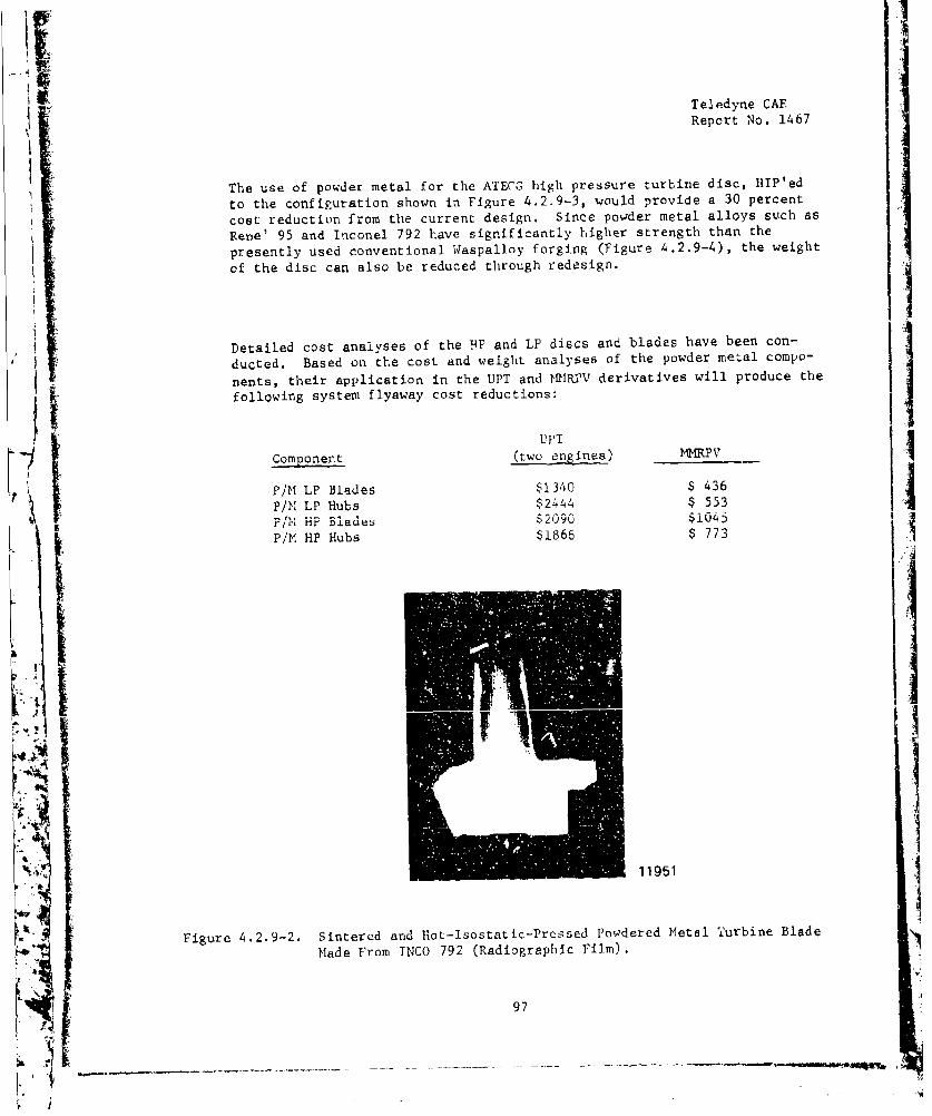
Teledyne CAF
Report No. 1467
The use of powder metal for the ATECG high pressure turbine disc, HIP'ed
to the configuration shown in Figure 4.2.9-3, would provide a 30 percent
cost reduction from the current design. Since powder metal alloys such as
Rene' 95 and Inconel 792 have significantly higher strength than the
presently used conventional Waspalloy forging (Figure 4.2.9-4), the weight
of the disc can also be reduced through redesign.
Detailed cost analyses of the .FP and LP discs and blades have been con-
ducted, Based on the cost and weight analyses of the powder metal compo-
nents, their application in the UPT and HMRYV derivatives will produce the
following system flyaway cost reductions:
"Componert (two engines) 1IRPV
P/M LP Blades $1340 $ 436
P/M LP Hubs $2444 $ 553Pit- HP Blades $2090 $1045
P/M HP Hubs $1866 $ 773
IA,
V iK.11951
Figure 4.2.9-2. Sintered and Hot-Isostatic-Pressed Powdered Metal Turbine Blade
Made From INCO 792 (Radiographic Film).
97
S--I-
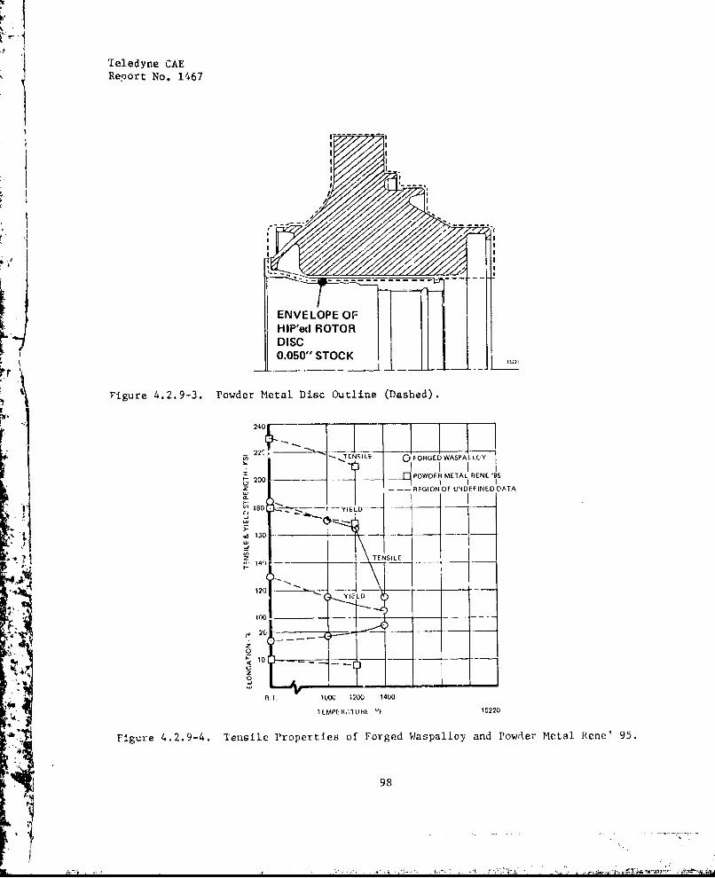
Teledyne CAEReport No. 1467
ENVELOPE~~IE OFREWAFLC
k1806ýý i-- -IS-RGONO NEFNDDT
vigue4.2.93. Poder Meal Dic OutineLD ahe)
Z 2D. PODE TENSILEN '
1130 -- YIEL
12
1100
20
A.T. I 0OO 1200 14 00
4UIMFERiALIFIE 'F 15220
Flgure 4.2.9-4. Tensile Properties of Forged Waspalloy and Powrer Metal Rene' 95.
98
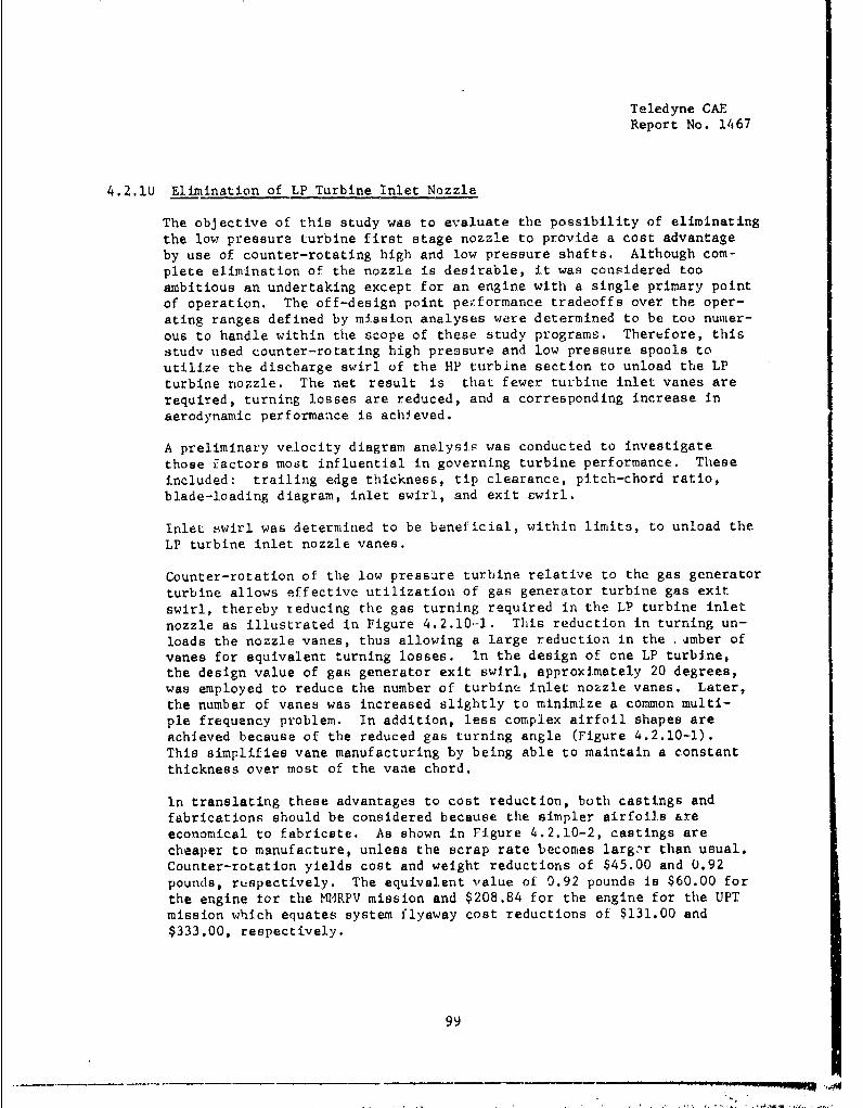
Teledyne CAEReport No. 1467
4.2.10 Elimination of LP Turbine Inlet Nozzle
The objective of this study was to evaluate the possibility of eliminatingthe low pressure turbine first stage nozzle to provide a cost advantageby use of counter-rotating high and low pressure shafts. Although com-
plete elimination of the nozzle is desirable, it was considered tooambitious an undertaking except for an engine with a single primary point
of operation. The off-design point peiformance tradeoffs over the oper-ating ranges defined by mission analyses were determined to be too numer-
ous to handle within the scope of these study programs. Therefore, thisstudy used counter-rotating high pressure and low pressure spools toutilize the discharge swirl of the HP turbine section to unload the LPturbine nozzle. The net result is that fewer turbine inlet vanes are
required, turning losses are reduced, and a corresponding increase inaerodynamic performance is achieved.
A preliminary velocity diagram analysis was conducted to investigatethose factors most influential in governing turbine performance. These
included: trailing edge thickness, tip clearance, pitch-chord ratio,
blade-loading diagram, inlet swirl, and exit swirl.
Inlet Hwirl was determined to be beneficial, within limits, to unload theLP turbine inlet nozzle vanes.
Counter-rotation of the low pressure turbine relative to the gas generator
turbine allows effective utilization of gas generator turbine gas exit
swirl, thereby reducing the gas turning required in the LP turbine inlet
nozzle as illustrated in Figure 4.2.10-1. This reduction in turning un-
loads the nozzle vanes, thus allowing a large reduction in the .'mber ofvanes for equivalent turning losses. In the design of cne LP turbine,the design value of gas generator exit swirl, approximately 20 degrees,was employed to reduce the number of turbine inlet nozzle vanes. Later,
the number of vanes was increased slightly to minimize a common multi-ple frequency problem. In addition, less complex airfoil shapes are
achieved because of the reduced gas turning angle (Figure 4.2.10-1).This simplifies vane manufacturing by being able to maintain a constantthickness over most of the vane chord.
In translating these advantages to cost reduction, both castings andfabrications should be considered because the simpler airfoils areeconomical to fabricate. As shown in Figure 4.2.10-2, castings are
cheaper to manufacture, unless the scrap rate becomes larger than usual.Counter-rotation yields cost and weight reductions of $45.00 and 0.92pounds, ruspectively. The equivalent value of 0.92 pounds is $60.00 for
the engine for the M4RPV mission and $208.84 for the engine for the UPTmission which equates system flyaway cost reductions of $131.00 and
$333.00, respectively.
99
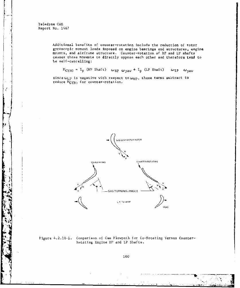
Teledyne CAEReport No. 1467
Additional benefits of counter-rotation include the reduction of rotorgyroscopic mroment loads imposed on engine bearings and structures, engine
mounts, and airframe structure. Counter-rotation of HP and LP shaftscauses these moments to directly oppose each other and therefore tend tobe self-cancelling:
*GYRO = 1p (B- Shaft) (iHP Wyaw + lp (LP Shaft) COLP t yaw
Ssince LP is negative with respect towup, these terms subtract to
*reduce MGYR(, for counter-rotation.
--A IGAS GENERAIOR ROTOR
VV
U
COIOTATING COUNTERRO1ATING
"U --- GAS TURNING ANGLE
L. r. TU.H.NE
,4343
A Figure 4.2.10--1. Comparison of Cas Flowpath for Co-Rotating Versus Counter-
Rotating Engine lip and LP Shafts.
100
- -

iI
Teledyne CAEReport No. 1467
CAST LP TURBINE INLET NOZZLE
Co-Rotating Shafts Counter-Rotatin& Shafts
Integral Casting Integral Casting
Vanes $ 230.00 Vanes = $ 210.00Qualify Casting 20,00 Qualify Casting 15.00Machining 350.00 Machining 350.00Deburring 25.00 Deburring = 15.00Insp, 25.00 Insp. 15.00
Total $ 650.00 Total $ 605.00
Net Coot Reduction = $45.00Net Weight Reduction = 0.92 pounds
FABRICATED LP TURBINE INLET NOZZLE
Co-Rotating Shafts Counter-Rotating Shafts
Shrouds $ 155.10 Shrouds = $ 155.10Cast Vanes - 160.00 Strip Stock Vaties 20.25
Qualify Castings 20.00
WeldinE 60.00 Welding 40.50
Deburring = 15,00 Deburring 1 0.00Insp. 25.00 1nsp. 20.00
Total $ 935.10 Total $ 718.85
Net Cost Reduction = $216.25Net Weight Red¶uction = 0.92 pounds
Figure 4.2.10-2. Cost Reduction of L11 Turbine Inlet Nozzle Through the Use ofCounter-Rotating Shafts.
101
• • ~~~~ -. .. i,, -............ .. U -:_.•,-
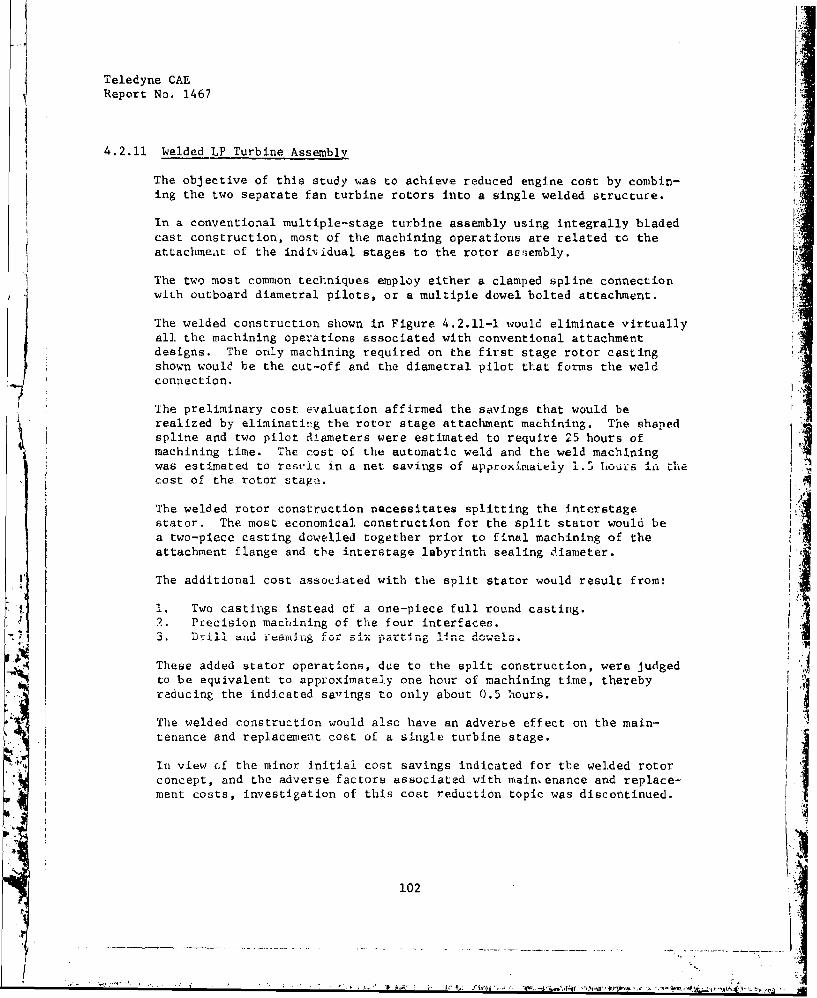
Teledyne CAEReport No. 1467
4.2.11 Welded LP Turbine Assembly
The objective of this study was to achieve reduced engine cost by combin-ing the two separate fan turbine rotors into a single welded structure.
In a conventional multiple-stage turbine assembly using integrally bladedcast construction, most of the machining operations are related to theattachment of the individual stages to the rotor assembly.
The two most common techniques employ either a clamped spline connectionwith outboard diametral pilots, or a multiple dowel bolted attachment.
The welded construction shown in Figure 4.2.11-1 would eliminate virtuallyall. the machining operations associated with conventional attachment
designs. The only machining required on the first stage rotor castingshown would be the cut-off and the diametral pilot that forms the weldconnection.
The preliminary cost evaluation affirmed the savings that would berealized by eliminating the rotor stage attachment machining. The shapedspline and two pilot diameters were estimated to require 25 hours ofmachining time. The cost of the automatic weld and the weld machiningwas estimated to resric in a net savings of approximately 1.5 liours iLL hte
cost of the rotor stage.
The welded rotor construction necessitates splitting the interstagestator. The most economical construction for the split stator would bea two-piece casting dowelled together prior to final machining of theattachment flange and the interstage labyrinth sealing diameter.
The additional cost associated with the split stator would result from:
1. Two castings instead of a one-piece full round casting.2. Precision machining of the four interfaces.3. DrillI aUtid r muaI 6 fJ.L -ix --....... .
These added stator operations, due to the split construction, were judgedto be equivalent to approximately one hour of machining time, therebyreducing the indicated savings to only about 0.5 hours.
The welded construction would also have an adverbe effect on the main-tenance and replacement cost of a single turbine stage.
In view cf the minor initial cost savings indicated for the welded rotorconcept, and the adverse factors associated with maintenance and replace-ment costs, investigation of this cost reduction topic was discontinued.
7'a
102
t
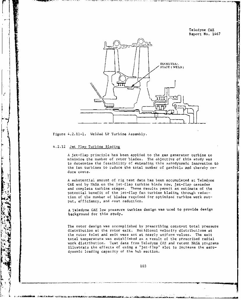
Teledyne CAE
Report No. 1467
DIAMETRALPILOT ( WELD)
Figure 4.2.11-1. Welded LP Turbine Assembly.
4.2.12 Jet Flap Turbine BladinJ
A jet-flap principle has been applied to the gas generator turbine tominimize the number of rotor blades. The objective of this study wasto determine the feasibility of extending this aerodynamic innovation tothe fan turbines to leduce the total number of gasfoila and thereby re-
duce costs.
A substantial amount of rig test data has been accumulated at Teledyne"CAE and by NASA on the jet-flap turbine blade row, jet-flap cascades
and complete turbine stages. These resultb permit an estimate of thepotential benefit of the Jet-flap fan turbine blading through reduc-tion of the number of blades required for optimized turbine work out-put, efficiency, and cost reduction.
A Teledyne CAE low pressure turbine design was used to provide design
background for this study.
The rotor design was accomplished by prescribing constnnt total pressure
distribution at the rotor exit, Meridional velocity distributions atthe rotor inlet and exit were set at nearly uniform values. The exittotal temperature was established as a result of the prescribed radial
work distribution. Test data from Teledyne CAE and recent NASA programs
illustrate the effects of using a "Jet-flap" slot to increase the aero-dynamic loading capacity of the hub section.
103
y ~~~~~~ ____________________
l~
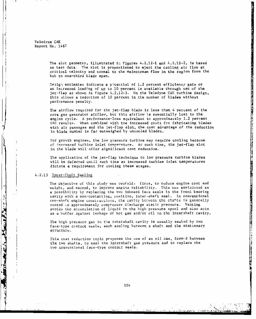
Teledyne CAEReport No. 1467
The slot geometry, illustrated in Figures 4.2.12-1 and 4.2.12-2, is basedon test data. The slot is proportioned to eject the cooling air flow atcritical velocity and normal to the mainstream flow in the region from thehub to one-third blade span.
Design estimates indicate a pitential of 1.2 percent efficiency gain oran Increased loading of up to 10 percent is available through use of thejet-flap as shown in Figure 4.2.12-3. On the Teledyne CAE turbine design,this allows a reduction of 10 percent in the number of blades withoutperformance penalty.
The airflow required for the jet-flap blade is less than 4 percent of thecore gas generator airflow, but this airflow is essentially lost to theengine cycle. A performance-loss equivalent to approximately 1.2 percentSFC results. When combined with the increased costs for fabricating bladeswith air passages and the jet-flap slot, the cost advantage of the reductionin blade number is far outweighed by uncooled blades.
For growth engines, the low pressure turbine may require cooling becauseof increased turbine inlet temperature. At such time, the let-flap slotin the blade will offer significant cost reduction.
The application of the jet-flap technique to low pressure turbine bladeswill be deferred until such time as increased turbine inlet temperaturesdictate a requirement for cooling these stages.
4.2.13 Inter-Shaft Sealing
The objective of this study was twofold: first, to reduce engine cost andweight, and second, to improve engine reliability. This was envisioned as
a possibility by replacing the two inboard face seals in the front bearingcavity with a non-contacting, positive, inter-shaft seal. In conventionaltwo-shaft engine constikuuLiJu&, the cavity bv-.wc,, the shafts iC ...n.r....
vented Lo approximately compressor discharge static pressure. Ventingavoids the accumulation of liquid Jn the high pressure spool and also actsas a buffer against leakage of hot gas and/or oil. in the intershaft cavity.
The high pressure gas in) the intershaft cavity is usually sealed by twoface-type contact seals, each sealing between a shaft and the stationarystructure.
This cost reduction topic proposes the use of an oil dam, formud betweenthe two shafts, to seal the intershaft gas pressure and to replace thetwo conventional face-type contact seals.
I104
-A

Teledyae CAEReport No. 1467
L E A D IN G T R AE D GE
SLOT AREA
14299
Figure 4.2.12-1. Typical Cooled Turbine Blade Schematic Illustrating Jet FlapAirflow.
SECTION A-A
EFFECTIVE THROUGJET STREAM 1 0 THROUGH FLOW
TRAJECTORY 1 / O, ROTOR BLADE
I MERIDIONAL VIEWS AIR SLUTDOWNSTREAM NEIGHTEI.UIU ANGLE
V0), TEST =91 ± 1 At9 COOLEI2/ UNCOOLED atO. TEST =VSotNIC 10310
JET-FLAP
Figure 4.2.12-2. Typical Cooled Turbine Blade Illustrating Jet Flap AerodynamicEffects.
105
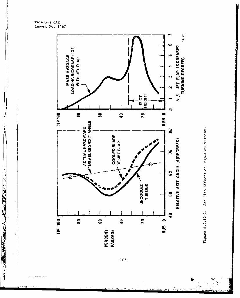
Teledyne CAEReport No. 1467
0) U
W W LL Rt
>- CC -
LL Ca
z m
0 *
0Mz Cca
4--
Ip U
II k

Teledyne CAEReport No. 1467
The preliminary design of the oil-dammed gas seal is shown in Figure4.2.13-1. A continuous supply of oil is directed into a rotating cavity
formed in the high pressure shaft assembly. A disc on the fan shaftassembly separates the oil into two columns. Any external pressure dif-ferential results in a height shift of the two columns, analogous to thefamiliar manometer operation.
Calculations indicate thac the liquid dam will support the expected peakintershaft cavity pressure differential of 140 psi.
A 0.71 HP loss is calculated for the liquid dam gas seal.
An approximate weight comparison was made between the liquid dam gas sealconcept and the conventional two-face seal, design. The dam seal wasfound to be approximately 0.7 pounds lighter due primarily to the actualweight savings at the two face seals and the stationary structure re-quired to support the face seal housings.
The hardware required to implement the liquid dam seal are basicallysimple metal components amenable to low cost production techniques suchas precision casting and powdered metal fabrication. The four detailsrequired for the liquid dam seal have bean estimated to cost about $6.00total, in production. The two face-type contact seals generally costabout $35.00 each in production. The precision machined shaft runnerthat provides the contacting surface for the face seal generally costsabout $15.00 each in production. Additional savings are realized by tteelimination of several stationary structure machining operations. Theoverall savings afforded by the liquid dam gas seal concept is approxi-mately $100 per engine. The addition of G & A and Profit and applicationof the weighting factors for engine weight related to mission producesthe following system flyaway cost reductions:
UPT (two engines) $434.00
M'YLPV = $190.00
An additional beneficial feature of the liquid dam seal is its basicsimplicity and non-contacting mode of operation. In contrast, face-type
107
'4j
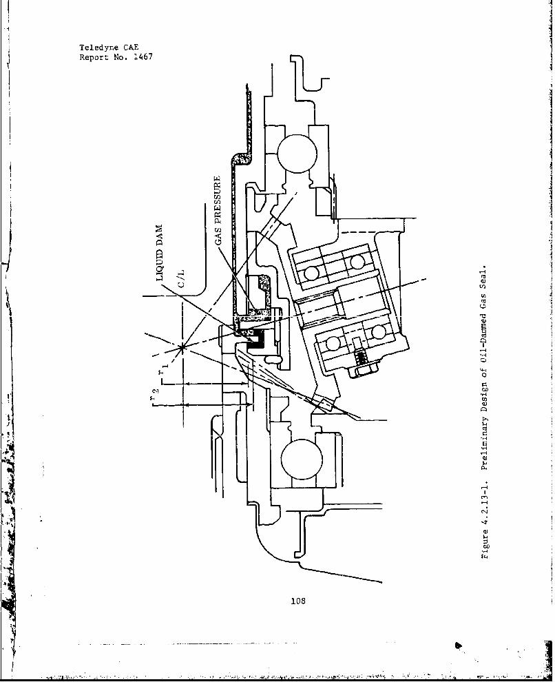
Teledyne CAEReport No. 1467
r I
- - C
- -
i lO8
/ Q
44
IV
108)
Teledyne CAEReport No. 1467
contact seals are sensitive to both environmental and dimensional con-ditions. With normal operating circumstances, face seals are subjectto wearout rates which involve both reliability and maintainabilitycosts.
The small cost reduction potential versus a substantial developmentcost (seal rig design, fabrication and testing) make the net payoffof this item small. Additionally, the calculated average rotationalspeed of the oil is reduced by approximately 70 percent for counter-rotating shafts, thus reducing the pressure differential which can besupported well below an acceptable level.
4.2.14 Gas Foil Bearings
The objective of this study was to achieve cost and weight reductionsthrough the use of gas foil bearings to replace rolling element bearingsand related lubrication system components.
Gas foil rotor bearings can provide considerable cost reduction by elimin-ating the normal circulating lube system and its attendant oil pump,lubrication lines, fittings, galleries and scavenge systemý
The low cost concept rnnidtrnr is t rbnirfe)nll in-rino nonfjoitn,, nn
shown in Figure 4.2.14-1. This bearing uses the working medium of theengine for its lubricant and essentially introduces no loss of enginecycle heat. The bearing is comprized of a thin tape having a series ofraised, resilient, formed supports. The supports provide radial compli-ance and Coulomb and viscous damping. Consequently, the bearing isstable for high speed rotating systems and provides effective dampingfor control of shaft vibration. The thickness of the hydrodynamic airwedge, which separates the journal from the bearing, is dependent on theviscosity of the air as well as its density, and the compressor dischargeair provides an ideal environment for successful bearing performance.
Tn dprPrmtnp the bpnefits of using a gas foil bearing, an analytical
study was performed on the baseline engine which uses an oil-lubricated
roller bearing located downstream of the turbine. Replacement of this
bearing with an air bearing would accomplish the following:
Cost would be reduced through the elimination of parts.
109
-'7
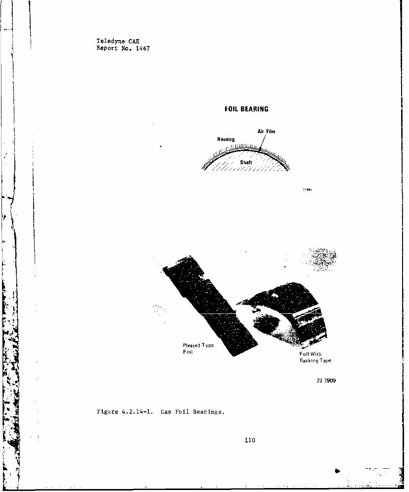
Teledyne CAE
Report No. 1467
FOIL BEARING
Air Film
Housing
1 / .
Shaft
I.
.44
* 'u,
Pleated Type
Foil •Foil With
BackinF Tape
73 7909
Figure 4.2.14-1. Gas Foil Bearings.
110
- ..... r- -- S
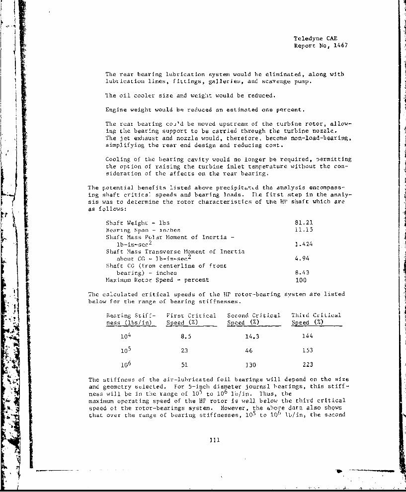
Teledyne CAEReport No, 1467
The rear bearing lubrication system would be eliminated, along withlubrication lines, fittings, galleries, and scavenge pump.
The oil cooler size and weight would be reduced.
Engine weight would be reduced an estimated one percent.
The rear bearing cou'd be moved upstream of the turbine rotor, allow-ing the bearing support to be carried through the turbine nozzle.The jet exhaust and nozzle would, therefore, become non-load-hearing,simplifying the rear end design and reducing cost.
Cooling of the bearing cavity would no longer be required, permittingthe option of raising the turbine inlet temperature without the con-sideration of the affects on the rear bearing.
The potential benefits listed above precipitated the analysis encompass-ing shaft critical speeds and bearing loads. rue first step in the analy-sis was to determine the rotor characteristics of the HP shaft which areas follows:
Shaft Weight - lbs 81.21Searing span - inches 11.15Shaft Mass Polar Moment of Inertia -
lb-in-sec2 1.424Shaft Mass Transverse Moment of Inertia
about CG - lb-in-sec 2 4.94Shaft CG (from centerline of front
bearing) - inches 8.43Maximum Rotor Speed - percent 100
The calculated critical speeds of the HP rotor-bearing system are listedbelow for the range of bearing stiffnesses.
Bearing Stiff- First Critical Second Critical 1r1IU CtiLLCalness (ibs/in) Speed (M) Speed (%) Speed (%)
4 104 8.5 14.3 1-4
105 23 46 153
106 51 130 223
The stiffness of the air-lubricated foil bearings will depend on the size
and geometry selected. For 5-inch diameter journal bearings, this stiff-ness will be in the range of l05 to 106 lb/in. Thus, themaximum operating speed of the HP rotor is well below the third criticalspeed of the rotor-bearings system. However, the above data also showsthat over the range of bearing stiffnesses, l05 to 106 lb/in, the second
4 11

Teledyne CAEReport No. 1467
critical speed may be below, coincident wi.th, or above the second criticalspeed of the rotor/bearings system. In the actual application, the bear-ing stiffnees would have to be adJu-,.ted to maintain an adequate margin
between the operating speed and the critical speed. This can be done byproper selection of foil compliance, bearing clearance, and pre-load.
With the critical speed versus bearing stiffness showing the capabilityof operating -.'ithin the shaft and be&ring requirements, the next step wasto determine the bearing loads. Figure 4.2.14-2 shows the calculatedjournal bearing loads for level flight, landing, and 3.5 radians/secondyaw maneuver. The present design allows for 5-inch diameter journalbearings. Thus, the start-up loads are very small, about 2 psi, assuming
a length-to-diameter ratio of unity. The most critical condition is thatassociated with the 3.5 radians/second yaw maneuver. Under this condition,
the maximum bearing load would approach 72 psi which is four or fivetimes the unit loadinS demonstrated to date on foil bearings. Althoughthis Is only a short duration maneuver load, it indicates that an in-crease in bearing span to reduce the bearing reactions to tL• gyroscopicSmomerý induced in th,_ maneuver, as well as an increase ir. bearing sizeneed to be considered, with the objective bLing a reduction in the maxi-mum radial unit loadin.n The present capacity of journal foil bearingshas been demonstrated to 20 psi unit loading with expected increases upto 30 to 35 psi available in the near future. An increase in bearing
span will have a linear effect on the reduccion of rhe bearing loads.Thus, twice the bearing span would halve the gyroscopic moment loadingson the bearings. It can be seen that bearing span dimensions con onlybe increased minimally before the engine becomes longer and heavier,cancelling the potential advantage of using the gas foil bearings.
An increase in bearing size can be utilized to reduce the radial unitloading. An increase in bearing diameter Lan only be accommodated toabout a 6-inch diameter journal before it would begin to affect the aero-dynamic flowpath of the engine. An increase in bearing length beyond a
length-to-diameter ratio of unity at the diameters (which is beinginmrncrinrPd) begins to be self-defeating because the alignment capa-bility to provide film convergence over the full leaf begins to drop ott,lowering the unit loaz. capacity.
Although the gas lubricated foil bearings display potential cost andweight savings, it is recommended that further investigations be suspen-
ded for the baseline engine until such time that toe unit loadingcapacity of these bearings is considerably enhanced.
4 4.2.15 SLnpliliLd Lubrication System
The objective of this study was to achieve cost and weight reductionsl'y means of a simplified lubrication system. To determine the best possi-
ble lubrication system, a number of candidate systems were investigated for
feasibility and a matrix of the combinations (candidate. systems versus arealubricated) was made.
112
.lit•
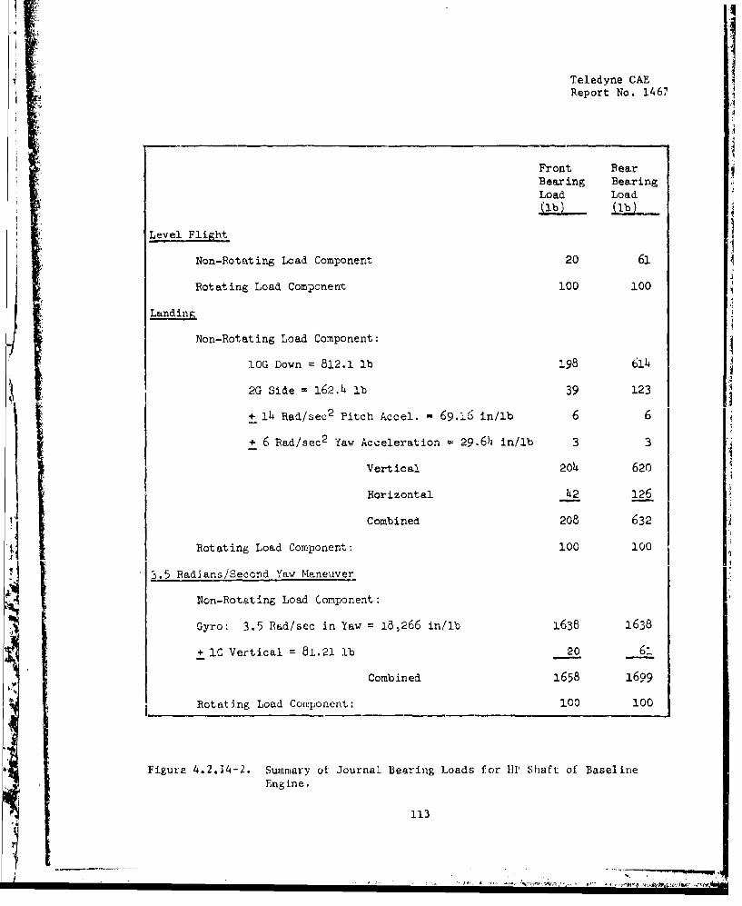
4ITeledyne CAEReport No. 1467
Front BearBearing Bearing
Load Load(1b)
Level Flight
Non-Rotating Load Component 20 61j
Rotating Load Component 100 100
Landing
Non-Rotating Load Component:
lOG Down 812.1 lb 198 61h
2G Side = 162.4 lb 39 123
+ 14 Rad/sec 2 Pitch Accel. = 69.6, in/lb 6 6
+ 6 Bad/sec 2 Yaw Acceleration 29.64 in/lb 3 3
Vertical 204 620
Horizontal 42 126
Combined 208 632
Rotating Load Component: 100 100
3.5 Radians/Second Yaw Maneuver
Non-Rotating Load Component:
Gyro: 3.5 Rad/sec in Yaw = 1B,266 in/lb 1638 1638
+ I Vertical = 81.21 lb 20 61
Combined 1658 1699
Rotating Load Component: 100 100
Figure 4.2.14-2. Summary of Journal Bearing Loads for U1P Shaft of BaselineEngine.
113
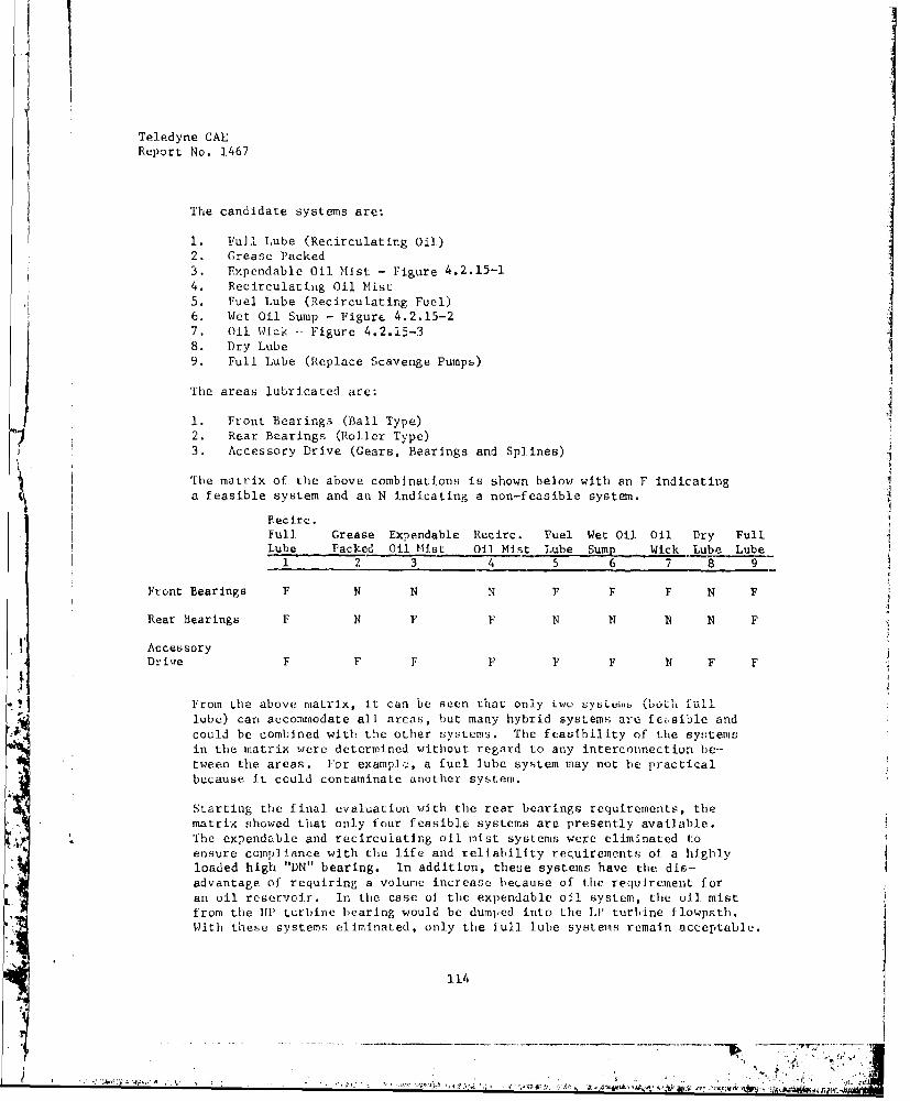
j
Teledyne CAL
Report No. 1467
The candidate systems are;
1. Full Lube (Recirculating Oil)2. Grease Packed3. Expendable Oil Mist - Figure 4.2.15-14. Recirculating Oil Mist5. Fuel Lube (Recirculating Fuel)
6. Wet Oil Sump - Figure 4.2.15-27. Oil Wick -- Figure 4.2.15-38. Dry Lube
9. Full Lube (Replace Scavenge Pumps)
The areas lubricated are: ]1. Front Bearings (Ball Type)2. Rear Bearings (Roller Type)3. Accessory Drive (Gears, Bearings and Splines)
The matrix of the above combinations is shown below with an F indicatinga feasible system and an N indicating a non-feasible system.
Recire.Full Grease Expendable Recirc. Fuel Wet Oil Oil Dry FullLube Packed Oil Mist Oil Mist Lube Sump Wick Lube Lube
1 2 3 4 5 6 7 8 9
Front Bearings F N N N F F F N F
Rear Bearings F N F F N N N N F
AccessoryDrive F F F F F F N F F
From the above matrix, it can be seen that only two 6yu•tumi ("bo-h full"lube) carn accommodate all areas, but many hybrid systems are febsible andcould be combined with the other systems. The feasIbility of the syfstemsin the matrix were deterMined without regard to any interconnection be-tween the areas. For example, a fuel lube system may not be practicalbecause it could contaminate another system.
Starting the final evaluation with the rear bearings requirements, ther matrix showed that only four feasible systems are presently available.
The expendable and recirculating oil mist systems were eliminated toensure complIance with the life and reliability requirements of a highlyloaded high "DN" bearing. In addition, these systems have the dis-advantage of requiring a volume increase betause of the requirement foran oil reservoir. In the case of the expendable oil system, the oil mistfrom the lip turbine bearing would be dumped into the LI' turbine ilowpath.With these systems eliminated, only the full lube systems remain acceptable.
3-14
V

Teledyne CAE1 ~Report No. 1467
COP SUPPLY LINE
OIL RESERVOIR
S~AI R-OIL M ST
IMPINGEMENT72 3994
Figure 4.2.15-1. Typical Teledyne CAE Expendable Oil MiHt R.!ear BearingLube System.
115
/g.t .(,,.
. .
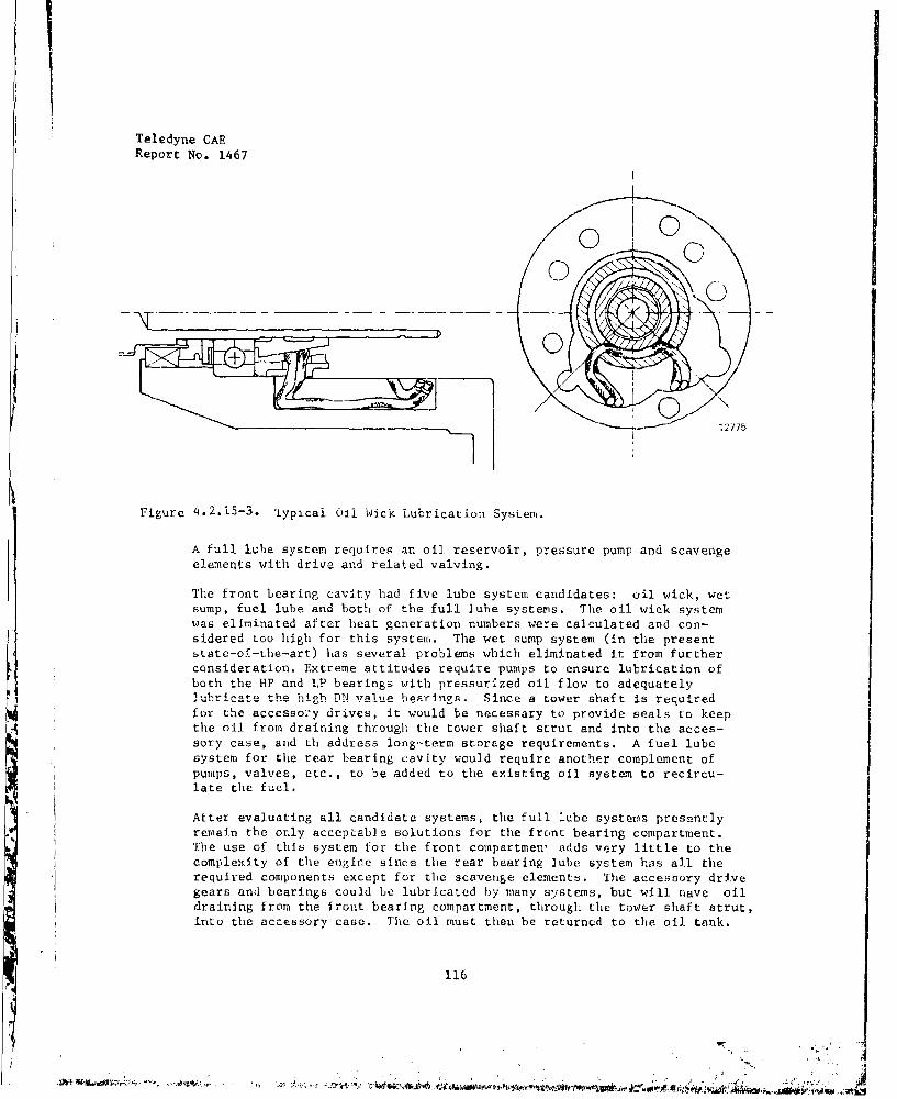
Teledyne CAEReport No. 1467
00
- 4--.•
J127
Figure 4.2.15-3, 'fypicai u1 Wick Lubrication SysLevi.
A full lube system requires an oil reservoir, pressure pump and scavengeelements with drive and related valving.
The front bearing cavity had five lube system candidates: oil wick, wetsump, fuel lube and both of the full lube systems. The oil wick systemwas eliminated after heat generation numbers were calculated and con-sidered too high for this system. The wet sump system (in the presentstate-of-the-art) has several problems which eliminated it from furtherconsideration. Extreme attitudes require pumps to ensure lubrication ofboth the HP and LP bearings with pressurized oil flow to adequatelylubricate the high DN value he-rings. Since a tower shaft is requiredfor the accesso:y drives, it would be necessary to provide seals to keepthe oil from draining through the tower shaft strut and into the acces-sory case, aud th address long-term storage requirements. A fuel lubesystem for the rear bearing cavity would require another complement ofpumps, valves, etc., to be added to the existing oil system to recircu-late the fuel.
After evaluating all candidate systems, the full lube systeras presentlyremain the only acceptable solutions for the front bearing compartment.The use of this system for the front compartment adds very little to thecomplexity of the engine since the rear bearing lube system has all therequired components except for the scavenge elements. The accesoory drivegears and bearings could be lubricated by many systems, but will nave oildraining from the front bearing compartment, through the tower shaft strut,into the accessory case. The oil must then be returned to the oil tank.
116
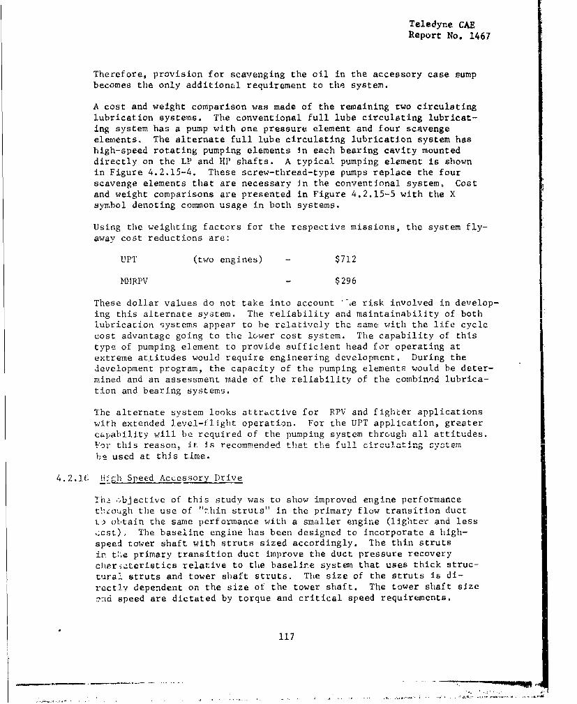
Teledyne CAEReport No. 1467
Therefore, provision for scavenging the oil in the accessory case sumpbecomes the only additional requirement to the system.
A cost and weight comparison was made of the remaining two circulatinglubrication systems. The conventional full lube circulating lubricat-ing system has a pump with one pressure element and four scavengeelements. The alternate full lube circulating lubrication system hashigh-speed rotating pumping elements in each bearing cavity mounteddirectly on the LP and HP shafts. A typical pumping element is shownin Figure 4.2.15-4. These screw-thread-type pumps replace the fourscavenge elements that are necessary in the conventional system, Costand weight comparisons are presented in Figure 4.2.15-5 with the Xsymbol denoting common usage in both systems.
Using the weighting factors for the respective missions, the system fly-away cost reductions are:
UPT (two engines) - $712
NI'RPV - $296
These dollar values do not take into account "'e risk, involved in develop-ing this alternate system. The reliability and maintainability of bothlubricavion systems appear to be relatively the same with the life cyclecost advantage going to the lower cost system. The capability of thistype of pumping element to provide sufficient head for operating atextreme attitudes would require engineering development. During thedevelopment program, the capacity of the pumping elements would be deter-mined and an assessment made of the reliability of the combined lubrica-tion and bearing systems.
The alternate system looks attractive for RPV and fighter applicationswith extended level-flight operation. For the UPT application, greatercapability will be required of the pumping system through all attitudes.For this reason, it is rpcrnmmended that the fu.11 •i-•,,1in system
be used at this time.
4.2.16i H.,gh Speed Accessory Drive
ThŽ .•bjective of this study was to show improved engine performancetlh-ough the use of "thin struts" in the primary flow transition ductt. obtain the same performance with a smaller engine (lighter and less,cst), The baseline engine has been designed to incorporate a high-
speed tower shaft with struts sized accordingly. The thin strutsin t:.e primary transition duct improve the duct pressure recoverychrr.iýteristics relative to the baseline system that uses thick struc-tural struts and tower shaft struts. The size of the struts is di-rectlJv depenIdent on the size of the tower shaft. The tower shaft sizeand speed are dictated by torque and critical speed requirements.
117
--" - - - ,, .
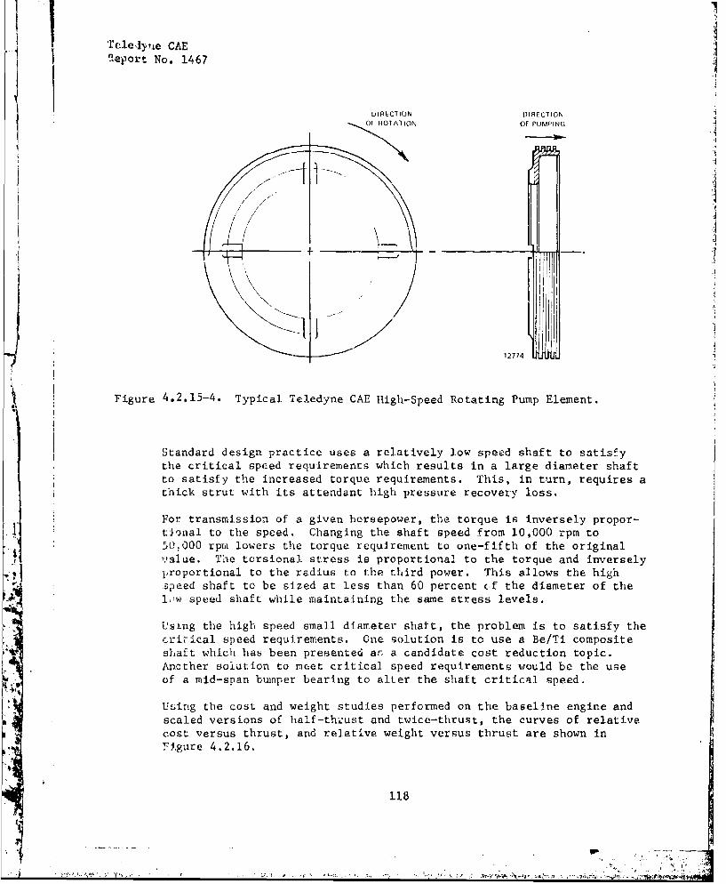
itleri .e CAEaeport No. 1467
DI RLCTIION VIRECTIONOf NR01ATION OF PUMPING -
12774
, Figure 4.2.15-4. Typical Teledyne CAE High-Speed Rotating Pump Element.
Standard design practice uses a relatively low speed shaft to satisfythe critical speed requirements which results in a large diameter shaftto satisfy the increased torque requirements. This, in turn, requires athick strut with its attendant high pressure recovery loss.
For transmission of a given horsepower, the torque is inversely propor-. tJonal to the speed. Changing the shaft speed from 10,000 rpm to
50.000 rpm lowers the torque requirement to one-fifth of the originalvalue. The torsional stress is proportional to the torque and inversely•proportional to the radius to the third power. This allows the high"•peed shaft to be sized at less than 60 percent (f the diameter of thel,!w speed shaft while maintaining the same stress levels.
Us,-ng the high speed small diameter shaft, the problem is to satisfy thecritical speed requirements. One solution is to use a Be/Ti compositeshaft which has been presented as a candidate cost reduction topic.Another solution to meet critical speed requirements would be the useof a mid-span bumper bearing to alter the shaft critical speed.
Using the cost and weight studies performed on the baseline engine andscaled versions of half-thzust and twice-thrust, the curves of relativecost versus thrust, and relative weight versus thrust are shown in*'!.igure 4.2.16,
-" ra- ;', ,
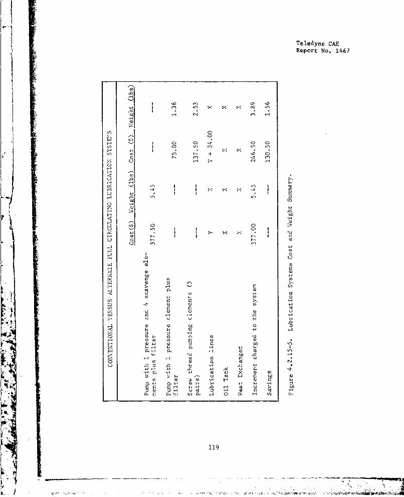
Teledyne CAEReport No. 1467
0 m 0n
P4
P o - Cl)L
0 r
>- --
4- U)U 0.
00
*-41
Va.
W x)V. 0
Cu4 u CW F$44
Q) U)U W V
HL > L H A Cl)(
4k C
Ci U) 4119
V U) 44 42-SAM
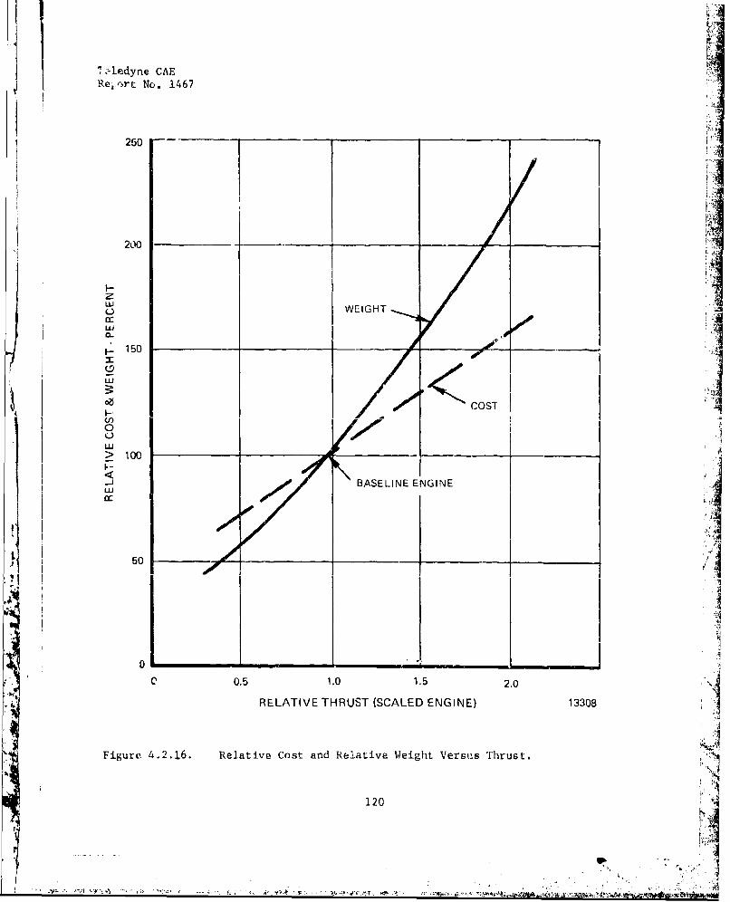
Želedyne CAE Vs
Re 1 .rrt No. 1467
250 -,___
1 1
200
L-
LU WEIGHT
C-,
1. 150
S.COST4I--:
LU> 100
-j" BASELINE ENGINE
50 _ 1:1!1
0.5 1.0 1.5 2.0
RELATIVE THRUST (SCALED ENGINE) 13308
Figure 4.2.16. Relative Cost and Relative Weight Versus Thrust.
120 V
C <S ThC-' .5g~lC~f~ V tPj~C< 4.J V ~f-
Teledyne CAEReport No. 1467
The use of thin struts improves the performance, thereby allowing thepressure recovery duct to be resized with an attendant change in theweight of the engine. Using the curves of Figure 4.2.16, it can beseen that as engine weight is reduced, the cost is reduced. Actualvalues for cost and weight savings require detailed analyses of the aero-dynamics, engine performance and mechanical configuration.
Although it is apparent that a cost and weight advantage can be derivedfrom the use of a high speed accessory drive, further studies to provideactual values are not recommended until specific engines are definedfor detailed analysis and cost/weight tradeoffs.
4.2.17 Controls and Accessories
The objective of this study was to examine the cost and weight reductionpotential of three currently available advanced technology components,and compare them to similar currently used production components. Thethree components evaluated were: (1) electronic fuel control logiL"system, in combinaticn with a rotary metering valve: (2) a low-cost,variable displacement piston pump; and (3) a fluidic logic system andair motor actuators to control nlet guide vane and interstage bleedvalve position.
The baseline engine for these cost analysis studies has functional control
system requirements which can be related to the current J00-CA-100 enginerequirements. The approach used in making the cost analysis was to sum-marize the required functions and compare them to the functions of thecurrent Jl00 control system, then add those control capabilities requiredto enable the current 3l00 system to control the baseline engine shown inFigure 4.2.17-1.
As indicated in Figure 4.2.17-1, the current technology system, as adaptedthrough additional functions to properly control the turbofan engine, iscostly and heavy. The advanced electronic control system cost is approxi-matph, 40 nprrant of that- of the currenr oncran wegh 6.5n-nlr(which translates to an additional system cost saving of $11,088/vehicle,
based on value of engine weight reduction for a trainer application) andhas a much smaller volume.
Electronic Control
The electronic fuel control system consists of three subsystems: theengine governor and control subsystem (electronic module); the start andsupervisory subsystem (electronic module); and the fuel metering subsys-tem (electronic motor and hydromechanical valve). The two electronicmodules, chassis-mounted, are presently in an industrial configurationand can be readily repackaged for flight. The fuel metering subsystemconsists of a stepper motor and a fuel metering valve. Since the threesubsystems are modular and small, they can be located in a variety ofplaces - this allows grcst flexibility in controls/engine and engine/airframe interfacing.
121
X []-ý14Jv: # - -,'J' . . • " '• • ' : • •: t`s''' ' r -M •• '";-°' ""'

Teledyne CAEReport No. 1467
S•C, o C) oC) C) 43
44j4
454
44,
L -4
V. 0
- H
12 443II122
' '.4 '.4
14 .. ..- -, ..•
4 ~.122
44.1 I 4, 4
Teledyne CAE
Report No. 1467
Rotor Metering Valve
To be functional and cost effective on a wide range of operational engines,a fuel metering unit must have the following characteristics:
Accurate (minimum metered flow of 20 to 70 pph with 3 to 5 pphaccuracy)
Low Cost
Reliable (especially clog-free)
Positive Actuation
Fail-Fixed Capability
After reviewing and rating a number of metering techniques, Teledyne CAEdetermined that the rotary valve/stepper motor approach is by far themost promising. Teledyne CAE has experience with all of the techniquesinvestigated.
The two critical characteristics in which the rotary valve/stepper motorexcels are accuracy and fail-fixed capability. Small gas turbine enginesrequire highly accurate metered fuel flow at various engine operatingconditions. The most stringent accuracy is required when the control ison starting or deceleration mode at low flows (20 pph), with a possibleaccuracy requirement of 3 pph. The rotary valve satisfies this require-ment.
The rotary valve/stepper motor fail-fixed feature provides fixed flow whenthe flow package loses electrical power. A permanent magnet steppermotor, geared to the metering valve, holds the valve in its last commandedposition. For manned aircraft, executive action can then be taken tooverride the control.
123
- L
Teledyne CAL
Report No, 1467
Fuel Pump
Although a variety of candidate pumping systems can be used, centrifugal,piston, gear, or various combinations depending on the specific require-ments, a variable displacement piston pump developed by the National GasTurbine Establishment (NCTE) appears to have great potential as a central
element in a low-cost simplified control system.
The NGTE pump (Figure 4.2.17-2) consists of three axially-disposed plun.-
gers housed within a rotor. Plunger stroke is determined by a variable-angle cam plate controlled by a servo piston. Operating pressure is
regulated by a spill valve that maintains a constant delivery pressure.
This pump has the capability of providing a simple governor, fuel meter-ing, and a pumping system at under $1,000 production cost and 4 to 5pounds in weight.
Fluidic Logic for IGV, IBV Control
Variable inlet guide vanes (Icy's) and interstage bleed valves (IBV's)prevent starting problems in high-pressure-ratio axial compressors. Thevariable L(v lowers the compressor blade angle-of-attack at low rpm'sand thus reduces blade loading. The IBV lowers blade loading by reducingback pressure on the compressor's front stages,
IGV's and IBV's must be actuated by services that are in turn driven bylogic systems. Teledyne CAE has reviewed one promising logic device andtwo actuation devices.
Fluidic Logic System
The Bendix fluidic logic system schedules vane (or bleed valve) positionas a function of compressor corrected speed. The logic compares pressuresaL fuur lucauiuub (iLLLub~ige, cumprusuur discharge, compressor inlet and
engine compartment or fan discharge) - and then commands the actuator.
Fluidic Actuator
The Bendix actuator (Figure 4.2.17-3) operates by pressure differentials
across a diaphragm. The advantage of this actuator is that the logic andactuator can be packaged in a compact unit and bolted directly to theengine (in the case of the 1BV, the logic, actuator, and bleed valve canbe packaged in one unit and bolted directly to the engine bleed port).
124
2I=
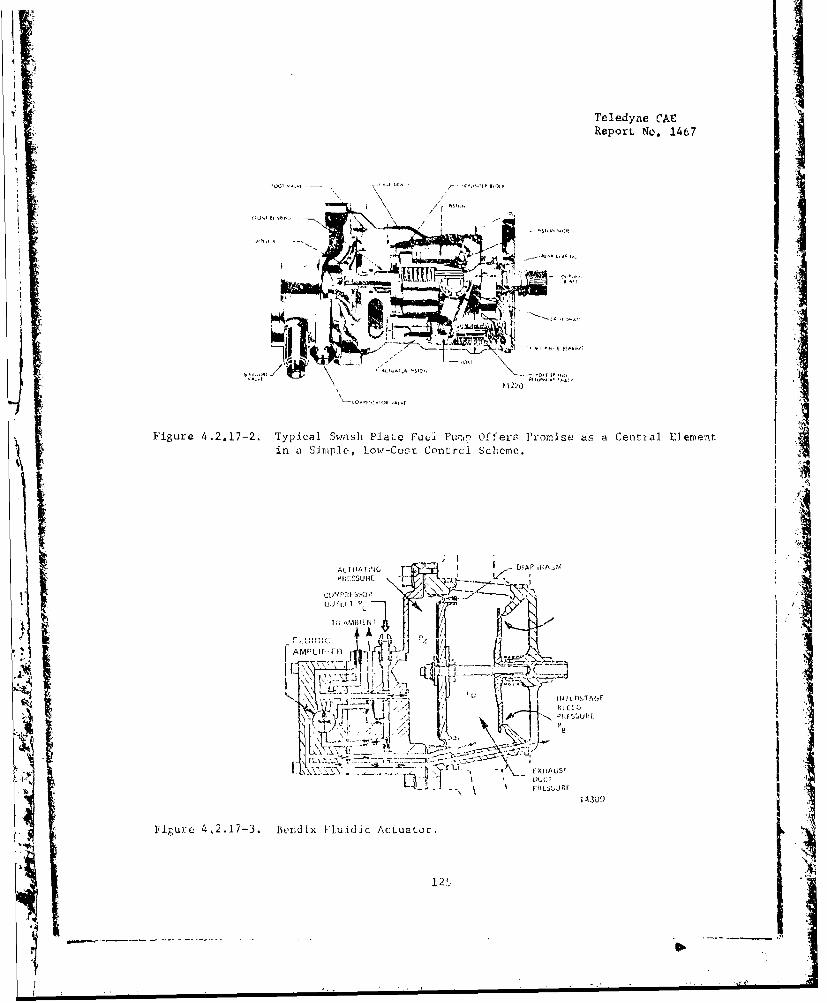
Teledyne CAEReporL No. 1467
\F V
Figure 4.2.17-2. Typical Swash Plat;e Fu Pul•p Off'eas Promise as a Cential Element
in a Simple, Low-Cosv Control Scheme.
; I
A I-II 'll I "I', AP: RA
41,, II•I t it7 E L. .
.. ... ' 1 .1 .. . • x- • •
A..
'k)(HAU5'4 . .. 'i •
{~~~~~4 j Q
Teledyne CAEReport No. 1.467
Air Motor Actuator
The CECO air motor Is compact and low cost. The motor is simply a shaftdriven at high speed by a small air turbine. The turbine is driven bycompressor bleed air after engine start and by bottled compressir airduring engine start.
The Bendix System (fluidic logic plus fluidic actuator) is already beingevaluated on another Teledyne CAE progr-m for use in driving variableIGV' s.
Self Test and Diagnostics
The ability to detect a control system malfunction within a hvryromechani-cal system is limited or impractical, difficult, and expensive, The ad-vanced electronic unit will have a malfunction detection capability builtInto the soft-ware. For RPV vpplications, this self-test feature will, on 2detection of a malfunction, switch the control to "fail-fixed" mode toassure mission completion. In man-rated applications, this feature will Ialso signal the pilot that a control system. failuze has occurred, thusenabling executive action to be taken while the control remains in thefail-fixed mode until override.
The electronic control is readily adaptable to engine diagnostic and con-dition monitoring systems. By means of an on-board events recorded, en- I
gine control and other criLical parameters can be monitored and recordedfor analysis by ground support equipment. Cost of this on-board equip-ment is on the order of $6-20,000 per aircraft, depending upon the degreeof sophistication employed, but should return many times that in preven-tative maintenance.
Also under investigation at Teledyne CAE is a method of locating degrada- "tion through spectral analysis. The engine noise characteristics are 41recorded sp.cti.ograp'.cally al ntnerva', c nd vari••tions can be attri-butcd to degradation of various components by signature analysis.
In view of the $13,000 tinimum savings available per engine, it isrecommended that the necessary programs to develop these control systemtechniques be pursued.
Teledyne CAE further recommends that on-board diagnostics and signatureanalysis be considered for future integrated instrumentation/diagixostic-lisplay systems.
4.2.1 Engine Specification Chges
The objective of this task was to review military specifications appli-cable to engine design, development and testing, identify inappropriaterequirements, and recommend cost reducing changes.
126
Teledyne CAEReport No. 1467
?MIL-E-5007D* was selected as the prime source of general technical require-ments for engines, MIL-E-5007D and its U.S. Navy counterpart (AS2684) areintended to provide guidance (see Section 2.2.1) to technical specialistsof DOD orocuring activities in imposing requirements on specific engines.
Ii, Teleayne CAE's previous experience, the requirements of MIL-E-5007Dhave been considerably modified through coordination between Teledyne CAEand procuring activity specialists to ensure the imposition c.f cost-effective requirements. Such modifications are included in the modelspecificacion for the J69-T-25 (T-37 trainer) and the J69/J100 (RPVseries).
This experience was applied to assess the requirements of MIL-E-5007Das they apply to a UPT or MRPV engine. Figure 4.2.18-1. provides a tabu-lation of 5007D requirements (by paragraph number and title). Adjacentto each requirement is listed the status of that requiremant in a cur-rently flying engine together with a comment on its probable need in
the UPT or M¶RPV nission!.
During the APSI studies, thz Aerospace lndustrles Association (A.I.A.)concurrently completed a review of MIL-EL-5007D which re-emphasized theneed to crItique that -pecification at each instance of specific applica-tion. The A.I.A. study reported1 (Figure 4.2,1R-2) that "blanket"
imposition of MIL-E-500713 could have a maj )r development cost impact assnown in Figure 4.2.18-2 (which is reproduced from that report).
In a subsequent definition of derivative engines for specific applica-tions, Teledyne CAE suggests chat citiqulng of specificatirns for cost-effectiveness be continued as a formal task. The systems cost method-o'cgy/techniques evolving at 'Cledyne CAE as a result of APSI participa-tion, furthered by the JTDE life cycle cost computer model for enginedesign, will be of immense benefit in formal evaluation of specificationcost effectiveness. Some specific topics for critAque are discussedbelow,
4.2.18.1 Armament Gas Ingestion (3.1.2.10.6)2
The need for inclusion of on engine capability to operate with armamentgas ingestion ol-viously depends on the mission. If the USAF and weapons
* MIL-E-5007, Military SpecifJcati.on Engines Aircraft, Turbojet andTurbofan - General Specilication for, (15 October 1973)
1 Aerospace Industries Association of America, Inc., Project AGE
Recommendations; 1 March 1974
2 Paragraph numbers from MIL-L-50071) are shown in. parenthesis.
127
- ..- - - ,.4! J
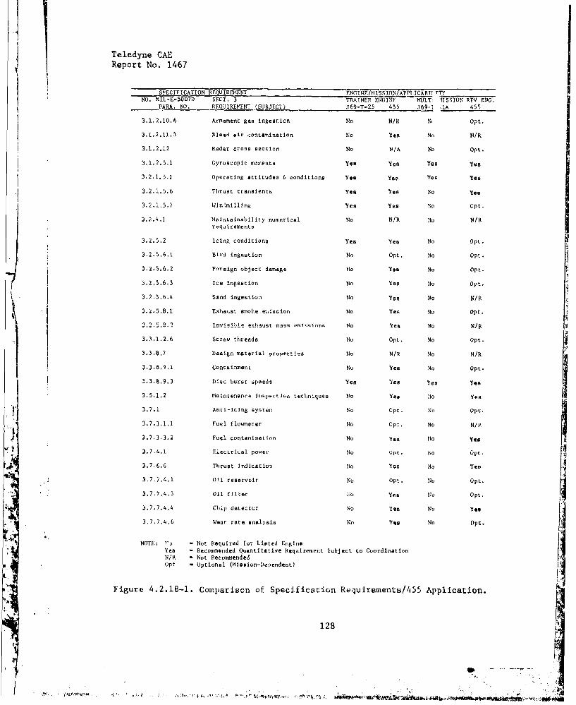
Teledyne CAEReport No. 1467
SPECIFICATION REQU IRElENT FNC IN /ISSION/APPICABI' TTYNO. MIL-E-5007D SECT. 3 TRAINER ENGINE MOLT, IISSION RPV ENG.
PARA. NO. REQUIREMENT (S.BJECT) J69-T-25 455 369-1 IA 455
3.1.2.10.6 Armament gas ingestion No N/R N' Opt.
3,1.2,11.3 Bleed air contamination No Yes No N/R
3.1.2.12 Radar cross section No N/A No Opt.
3.1.2.5.1 Gyroscopic moments Yes Yea Yes Yes
3.2.1.5.1 Operating attitudes & conditions Yes Yes Yes Yea
"3.2.1.5.6 Thrust transients Yes Yea No Yes
3.2.1.5.7 Win'.milling Yes Yes No Opt,
3.2.4,1 Maintainability numerical No N/R No N/Rrequirements
3.2.5.2 Icing conditions Yes Yes No Opt.
3.2.5,6.1 Bird ingestion No Opt, No Opt.
3.2.5.6.2 Foreign object damage No Yes No Opt.
3.2.5.6.3 Ice ingestion No Yes No Opt.
3.2.5.6.4 Sand ingestion No Yes No N/P.
3.2.5.8. Exhaust smoke et,,ission No Yes No Opt.
2.2.ý.8.2 invisible exhaust m9ýR mi lInso No Yes No N/R
3.3.1.2.6 Screw threads No Opt. No Opt.
3.3.8.7 Design material properLies No N/R No N/R
3.3.8.9.1 Containment No Yes No Opt.
3.3.8.9.3 Disc burst speeds Yes 'lea Yes Yes
3.5.1,2 Maintenance inspection techniques N:o Yes No Yea
3.7.1 Anti-icing system No Opt. No Opt.
3.7.3.1.1 Fuel flowneter No Opt. No N/N
3.7.3.3.2 Fuel contamination No Yes No Yea
3.7,4.1 Electrical power No Opt. No Opt.
3,7.6.6 Thrust indication NO Yes No Yes
3.7 7.4.1 011 reservoir No Opt. No Opt.
3.7.7.4,3 Oil filter 4o Yeas No Opt.
3.7.7.4.4 Chip detector No Yea No Yes
3.7.7,4.6 Wear rate analysis No Yes No Opt.
SNOTE: ?'j - Not Required for listed EngineYes - Recommentded (Nantitative Requirement Subject to CoordinationN/R - Not RecommendedOpt - Optional (Mission-Dependent)
Figure 4.2.18-1. Comparison of Specification Requlraments/455 Application.
128
4' "70TY-c s'4'., 'eq-M.c ,tVl! �. t•~t4t -ik l:..o •as4,r
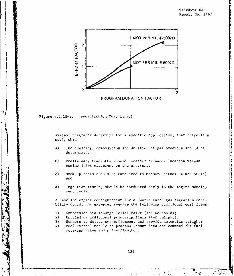
Teledyne CAEReport No. 1467
MQT PER MIL-E-5007D
0
U-
MOT PER MIL-E-5007CoA,
01 2
PROGRAM DURATION FACTOR
Figure 4.2.1.8-2. Specification Cost Impact.
system integrator determine for a specific application, that there is aneed, then:
a) The quantity, composition and duration of gas products should bedetermined;
b) Preliminary tradeoffs should consider ordnance location versusengine inlet placement on the aircraft;
c) Mock-up tests should be conducted to measure actual values of (a);and
d) Ingestion testing should be conducted early in the engine develop-ment: cycle.
A baseline engine configuration for a "worst case" gas ingestion capa-bility could, for example, require the following additional cost items:
1) Compressor Stall/Surge Relief Valve (and Solenoid);2) Uprated or additional primer/igniters (for relight);
3) Sensors to detect surge/flameout and provide automatic relight;4) Fuel, control module to process sensor data and command the fuel
metering valve and primer/igniter.
129

Teledyne CAEReport No. 1467
A rough order of magnitude (ROM) estimate of added acquisition cost for
the above complement is $3500/aircraft in a twin engine installation. and
$350/aircraft/year in operation and support (0 & S) costs. The added
weight would have an airframe cost penalty (see Section 2.5). However,if airframe inlet or ordnance station changes are feasible options, theycould be traded off against the foregoing costs. As a third option, anengine gas ingestion kit could be developed to ecuip type variations ofmultiple-role aircraft that have an ordnance delivery mission.
4.2.18.2 Icing; Bird In&estion, and SandInestion (3.2.5.2/3.2.5.6.1/3.2.5.6.4)
These requirements should be. evaluated with the same rationale as gasingestion because they are also mission and, to some extent, airframe/configuration dependent.
4.2.18.3 Mass Moments of Inertia; Externally Applied Forces (3.1.2.4 & 3.1.5)
These requirements can be translated into cost consequences, for a givenengine and airframe, when material selection, structural analysis andweight impact are assessed.
The Mass Moments describe (but do not specify the value of) forces thatan engine can impose on the airframe. The cost impact is, therefore, con-tained in the interactive category (see Section 2.2.5).
The Externally Applied Forces (gyroscopic moments) specify momentary andconstant angular velocities which the aircraft may impose on the engine.These are specified as:
3.5 radians/second with a +/- lg load for 15 seconds
1 4 rRdIans/second (with various loads) for continuous duty
These requirements have initial impact on development and acquisitioncosts. Also, when the requirements result in added weight, they alEoimpact airframe costs.
4.2.18.4 Bleed Air Contamination (3.1.2.11.3)
This requirement which lists permissible limits of certain contaminants(e.g., C02 @ 5000 parts/million of bleed air) should not be specifiedfor RPV's. If safety requirements dictate its use for manned aircraft,the principal costs will accrue in development for test and demonstrationpurposes. However, engine bleed air may also be used for non-life sup-port purposes (e.g., gun purge, rain removal, equipment cooling) in
which case contamination levels may not be significant.
130i
Teledyne CAE
Report No. 1467
4.2.18.5 Radar Cross Section (RCS) (3.1.2.12)
This requirement can lead to unnecessary test cost if imposed on the basic(i.e., uninstalled engine). Radar reflectivity is a property of theengine inlet, which design is normally proposed by the airframe contractorand coordinated with the engine contractor. Also, RCS reduction is atradecff candidate. For example, an aircraft equipped with a high by-pass ratio turbofan (implies a high engine RCS) may have a lower totalaircraft RCS than an aircraft with a low by-pass ratio fan and externalfuel stores. The foregoing example assumes that each aircraft isdesigned for the same mission.
4.2.18.6 Operating Attitudes (3.2.1.5.1)
This requirement impacts the mechanical design and cost of the enginelubrication system because it sizes the scavenge capability of the oilpumps. An ROM estimate for a twin-engine UPT-type application, with a30-second, 90 degrees (vertical) operating capability, Is:
1) Scavenge Pumps/Aircraft (Additional) 22) Increase in Engine Acquisition Cost (x 2) $7003) Increase in Weight (including lines and tank) 7 pounds4) Total A/C Acquisition Cost $2289
4.2.18-7 Thrust Transients (3.2.1.5.6)
This requirement lists 18 or more precisely specified thrust transients.It should be critiqued for two reasons:
1) For some applications (e.g., RPV's), one or two thrust transientsmay be sufficient to describe any foreseeable requirements.
2) The "corners" of these operating transients may add unnecessarydevelopment and test cost. For example, idle to maximum thrustavailable is specified as seven seconds from S/l to 1OK feet.Eight or n.ne seconds may be both adequate Luf Lhe .... ...•, andreadily attainable for a specific engine but demonstrating thatlast one or two secoads may double the cost of development andproductr.on acceptance testing.
131
STeledyne CAEReport No. 1467
4.2.19 Cost Reduction Analysis Summary
Shown in Figure 4.2.19-1 is a summary of the 18 specific cost reductiontopics and their effect on the following factors;
'Change in compox..nts acquisition cost
'Change in engine weight
- Change in engine SFC
-'Change in system cost due to weight for the UPT
'Change in system cost due to weight for the NNRPV
'Change in system cost due to SFC for the UPT
'Change in system cost due to SEC for the MMRPV
* System flyaway cost reduction for the UPT
'System flyaway co-t reduction for the MxIRPV
Note that all dollar figures shown are in 1975 dollars.
A
132
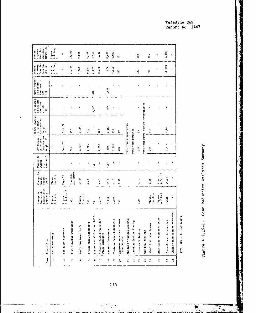
Teledyne CAEReport No-. 1467
B.�0 WI 0241� 02,4 0.-I 412 �. 0' 3 - 0 3- 0
4I�
4 44 0* I '4 0' '4 02 02 02 0 -0
3020u 043-4 020202.200202 0 '4 I 00.02 QOr . 02 . - 02 0' 0'444.U'0 3.402 .- 434.0 .2 �0 0234 02 -2 32 02
340204 WI .4 02410 .'- $.-. 0 34 0 0 01 0' 0 02
00-304' -" - 40 02020- 02' 02 '4 340-.-I 0 0 0. .4 '4 02 02 0243.4,0.- 23402 02 02 0' .0 02 021 02 0- .4
0
I I I I I I I I I I I
020- '40.4 '402 �U-. 0 '4
03.0, 02.4 U 12
03.444� 02.030 U CU3-' 0- 02 .3
4402 I I I I I 02 I - I I I H I I IH 02 02 0'3.00002 0414044 02
1--- -- ________________ LA
002
440 '4 3. I34 I 0'
00- .0 02 023.024(0 '4 5;;
- '4 02 02 02 0 4�- 02 .0 -3-0' H02�3.�02 '4 .- 102'4 0'V, 34
0140 40 0-
41402 41�023 02 0' 0. C.341W�
02 02 02I 0- 01 3. 04 I
4.20. .011 02 I '4 '4 1-' � '4 I024(04 41 0' 34 34 0' 02 31 - - 02 2
I. 0024 In 02 02 0' 34 02 '4 0' 0' '4 0' 143.30414 4 0' - 02 0 40020202
3. 3- 02 -2 - 0234 �4024�4 02 02
0 �g2�02 2o I I I I I r- I I I I I I I4 02 02
.4-iU 02 .4
________ _________________________ wfrIO -.3.
09.0 til
04020 0* 41 02 02 0 02 I- 02 0 '4 0.02.2.02 0234 02 031 '4 '4 .. 0' I- 02 0234
U15W-' jt 4 02 . . 02 -2 . '4 . C0. 0-'4 ..I 02 02 .4 -4 0 0 4 0,0 34
00 .4-4
Ii'40402 - 3- U
41'402 02 .4 3- I4130�414 41' 01 4102 41402 032 4'4 3- 0' .3 002 402 02 I _
�i&i k'-. 02 0234 4 1- '4 02 '4 0 toC' 0234 �.4. 000 -.4. 00' 4.02 '-4 0 '4 .2.00<0 0-4 0-�o 02 0--S 02 '4 32 02 4 02 02 0-4 3.4 3-
___________________________________________________ 42Ca
Q1 00 0 0'4 0. 0 41 . 4 04 .0
0 (2 41 4 3 .02 (0 - 0 4
4 0 0 I 41 3 UO 0 4 LA 344 41 Cl '404 0241 4 3 3 4 3 4 3 0 41 0O 0-� 41 W 0 0 0 V 41 4 0. 0 3 0-
0 0 4 41 0 0. 3. H 02 3 4 3 0 0-0. .0 I' C- * 05 02 00 3' 0 3 .2 0' 02
0 C' 4Q�3 44 *402 0 U 0 0 02 444 4
'4 41 41 U 410 3 04 41 4 .4 .0 u 0' .2 023 4 41 5 02 .24 041044.410 0 I) 0441 4 0 0 02 41 03 44 41 0 4 02 44 .4 C '0 02
30 7. .2 3. 4144 0� fl� 3�H0 3 Ia0 0 4'0U 4141 0'04 41 41 41 3 444 00 '4H 0.otl 41 II �.0�'0 0 4 41 <(030 �4A0.-43.4102'4 41 MIt 020- 4 4 '4 14. 00 U 41 4y. 41 .0 '4 04 3. 02'4 02 �2 H 0 0 4 0 0- 3 '00230402 0 41 41
41 1.. 0 141 -, 4 304 04 I � SW 0141 14 .0 401
02 02 .2 41 04 � � '44 .2 4 4 41 41 033 0 0 3 I 41 .0 0 - -41 4 41 5. 0 0- 0 41 0 -3 41 41 3 41 04 02 0 '1 0 0002 3. 0- U 02 02 023. 1.4 3. 0202 3 U 14 02 02 U 04 01
1.2 34 44 �0 02.14�- 02020 ,3Jfl402�402
133
-C
0I
-- - I - , - -- �4A0 . KY.;-.,
I a3
,•., •, • -• -•-• .- IL.I
Teledyne CAE
Report No. 1467
SECTION 5.0 - TECHNOLOGY ASSESSMENT
5.1 Metbodology; Status and Objectives
During the APSI system cost studies, many cost-influencing design deci-
sions were evaluated. Each evaluation was characterized by literaturesearches, calculations, and the repetitive process of interpretingreference tables to derive cost estimates.
The airframe-company studies emphasized an awareness of the engine's
airframe-cost. This awareness expands the scope of calculating LCCestimates and highlights the need to perform the important task ofsensitivity-testing and design/cost iteration. In conclusion, the needfor a computerized design-to-life-cost (DTLC) model became quiteevident.
Teledyne CAE, therefore, reviewed the usefulness of existing life cycle
cost models, including the models described in References 19 and 20, and
others encountered during prior Teledyne CAE programs. All the models
reviewed had- one or more of the following disadvantages:
Existing models are generally electronic-system oriented and are
best applied to a system of independently removable modules (e.g.,
circuit boards, trays or drawers) whereas engine maintenance is a
sequential process.
The models assume that the equipment's operating environment is
steady-state as opposed to the dynamic operating and stress envi-
ronment of gas turbine engines (as characterized by the UPT
composite mission described in Section 3.0).
The preparation and execution of programming (because of model
orientation) does not lend itself to interdisciplinary coordina-
tion. For example, an engine systems cost model should use (and
interact with) the engine's computerized performance presentationto identify the cost/life influence of engine match points in termsof component loads and temperatures.
The data output of most existing models provides a logistics plan-
ning function while requiring considerable interpretation for use
in evaluating engine cost/benefits tradeoffs. In particular, the
important cost element of engine/aircraft interaction is not
addressed.
In summary, an off-the-shelf model for engine use was not available, while
the work of adapting existing models to conduct frequent, timely, and
credible evaluations was found to be less cost effective than the develop-ment of an engine-oriented model.
135
1-4 34'"-a ,n
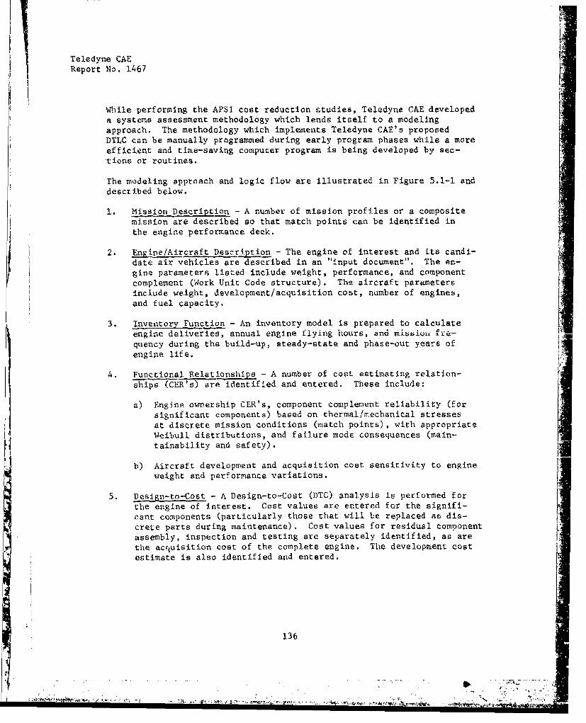
Teledyne CAEReport No. 1467
While performing the APSI cost reduction studies, Teledyne CAE developeda systems assessment methodology which lends itself to a modelingapproach. The methodology which implements Teledyne CAE's proposedDTLC can be manually programmed during early program phases while a moreefficient and time-saving computer program is being developed by sec-tions or routines.
The modeling approach and logic flow are illustrated in Figure 5.1-1 and
described below.
1. Mission Description - A number of mission profiles or a compositemission are described so that match points can be identified inthe engine performance deck.
2. Ljine/Aircraft Description - The engine of interest and its candi-date air vehicles are described in an "input document". The en-gine parameters listed include weight, performance, and componentcomplement (Work Unit Code structure). The aircraft parametersinclude weight, development/acquisition cost, number of engines,and fuel capacity.
3. Inventory Function - An inventory model is prepared to calculateengine deliveries, annual engine flying hours, and mission fre-quency during the build-up, steady-state and phase-out years of
engine life.
4. Functional Relationships - A number of cost estimating relation-ships (CER's) are identified and entered. These include:
a) Engine ownership CER's, component complement reliability (forsignificant components) based on thermal/mechanical stressesat discrete mission conditions (match points), with appropriateWeibull distributions, and failure mode consequences (main-tainability and safety).
b) Aircraft development and acquisition cost sensitivity to engineweight and performance variations.
5. Design-to-Cost - A Design-to-Cost (DTC) analysis is performed forthe engine of interest. Cost values are entered for the signifi-cant components (particularly those that will be replaced as dis-crete parts during maintenance). Cost values for residual componentassembly, inspection and testing are separately identified, as arethe acquisition cost of the complete engine. The development costestimate is also identified and entered.
136

Teledyne CAEReport No. 1467
oGzo
LhJUJ) -w2J
u>
o Lii
LU Z, t- L
-J Z a Uu
2-LU ~w mwcn OLUOQz.
z [ j- -oU LU ,,7
0 aI z I2 -Z UJ z ui M La.C a CLa L) z -. i :) 0
z >-CC z 04
z0 0 -
Z- '.00
La .4
F137
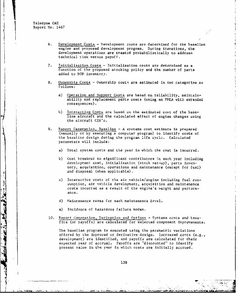
Teledyne CAEReport No. 1467
6. Development Costs - Development costs are determined for the baselineengine and proposed development program. During iterations, thedevelopment operations are treated probabilistically to addresstechnical risk versus payoff.
7. Initialization Costs - Initialization costs are determined as afunction of the proposed stocking policy and the number of parts
added to DOD inventory.
8. Ownershi2 Costs - Ownership costs are estimated in two categories asfollows:
a) operation and Support Costs are based on reliability, maintain-ability and replacement parts costs (using an FMEA with extendedconsequences).
b) Interactive Costs are based on the estimated cost of the base-line aircraft and the calculated effect of engine changes usingthe aircraft CER's.
9. Report Generation, Baseline - A systems cost estimate is prepared(manually or by executing a computer program) to identify costs ofthe baseline design during the program life cycle. Calculated
parameters will include:
a) Total system costs and the year in which the cost is incurred.
b) Cost breakout to significant contributors in each year includingdevelopment cost, initialization (stock set-up), parts inven-tory, acquisition, operations and maintenance (except for fuel)and disposal (when applicable).
c) Interactive costs of the air vehicle/engine including fuel con-sumption, air vehicle development, acquisition and maintenancecosts incurred as a result of the engine's weight and perform-ance.
d) Maintenance rates for each maintenance level.
e) Incidence of hazardous failure modes.
10. Report Generation, Derivation and Options - Systems costs and bene-fits (or payoffs) are calculated for selected component improvements.
The baseline program is executed using the parametric variationsoffered by the improved or derivative design. Increased costs (e.g.,development) are identified, and payoffs are calculated for theirexpected year of accrual. Payoffs are "discounted" to identifypresent value in the year in which costs are initially accrued.
138
P4iý TI W' z4T4
Teledyne CAeReport No. 1467
Where appropriate, expected ranges of parameters are derived toprovide for sensitivity testing and/or probabilistic treatment.
Teledyne CAE proposed the development of this Design-to-Life Cost method-ology, with computer-aided processing, in the JTDE program. Its commence-ment was authorized and the task is proceeding.
5.2 Technical Risk
In developing a method for forecasting the cost-benefit-result of design(and development) decisions, the technical risk factor and its cost im-pact has frequently been encountered. For example, if the technical riskis properly applied to the cost of development or to the estimate ofresulting benefits, is the decision cost-effective?
Recent DOD and AFAPL RFP's have demonstrated the government's apprecia-tion of technical risk and have promulgated methods for addressing itin design studies and tradeoff analyses. The suggested approach hasbeen to assign a risk factor to various technical objectives of an enginedevelopment program including: SFC, thrust-to-weight; reliabilitygrowth, etc., and rank the factors as low, moderate or high. The fac-tor ass~gnments tend to become point estimates (explicitly or implicitly)
because of the natural tendency to quantify a qualitative judgment, sothat resulting estimates may be In terms of percent of risk. However,if risk is to become a decision factor in a maturing cost/benefit analy-sis technique, its treatment will require some mathematical rigor. Thatis, there will need to be established a calculus of risk.
Bierman, et al (Reference 21) have addressed the subject in detail forroutine business decisions under conditions of uncertainty. Their con-cepts, however, appear equally valid for treating the technical riskfactor in engine cost/benefit analysis.
For example. Figure 5.2-1 illustrates a decision-curve for a hypotheticalengine development option, with a fixed development cost. In thisexample, the option is intended to achieve an LCC reducing performanceimprovement, and the accrued benefits (as a ratio of development cost)are treated probabilistically. In Figure 5.2-1, the resulting payoffat the expected value of 0.50 x 8-fold return - 4-fold return would Itend to suggest a "go-decision" for this opticn.
Teledyne CAE expects to develop the definition of this subject to thepoint that it can be utilized in executing thn DTLC model described inSection 5.1.
5.3 Technical Risk Estimates for Adaptive Components
In Section 5.2, the use of technical risk to evaluate cost/benefits wassuggested. In that example, tisk could be evaluated as a continuous
1
139
• e , . . .. . ... .. .. ... . . . . . . .. .. .. . ,-,~ mm •
4 1 g.- . ~ t.- .i>.r jt-.t..24
t~n~,4~ , *4.ptf.j4W ,.-p~g -. Mi
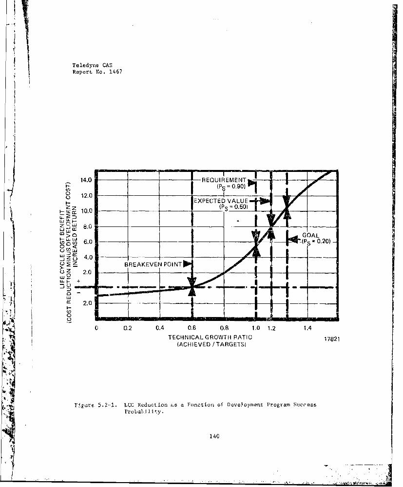
Teledyne CAEReport No. 1467
m -00-14.0 -REQUIREMENT
(P = 0.90)
S1 2 .0 _ _IeXPECTED VALUE ,
0 > GOAL,ao w ", w " 6 .0 -- 0 .20 ) -
0 <
BREAKEVEN POINT
I ____PONT_
z7 2.0 !ZG I 1 i
U- +
00 0.2 0.4 0.6 0.8 1.0 1.2 1.4
TECHNICAL GROWTH PATIO 17821(ACHIEVED / TARGETS)
SFýgure 5.2--l. LCC ReductLion as a Function of Development Program SuccessProbability.
140
Teledyne CAEReport No. 1467
function: increasing in proportion to technical reach. Teledyne CAEbelieves that approach would be appropriate where the objective can alsobe equated to a continuous variable (e.g., SFC, Fn, etc.).
A more elementry approach appears useful for single component developmentdecisions; that is, where development success is a go/no-go proposition.
For each component, preliminary (ROM) estimates of development costs andprojected benefits were developed. A single point estimate of develop-ment risk was then arrived at separately (to minirize bias) and definedas the probability that a successful component would not be derived fromthe development program. These two estimates were then combined to cal-culate a risk weighted benefit ratio (RB):
RB = (I - TR) (SLV - CLD)/CLD (1)BLV = (I - TR) (SLV - CLD)
Where:
RB = Benfit Fnit oTR - Technical Risk; hence (1 - TR) - Probability of Success
BLV = Benefit (Total) value in "Datum" dollars **CLD - Cost (Total) of developmentSLV = Total Savings in System Cost (given technical success)
By applying this elementary approach to some cost reduction candidates,it was determined that some development options had more cost merit thanothers. If, however, the number of prospective applications increases,or if the 0 & S cost changes, the potential benefit ratio will alsochange.
In summary, it is believed that the introduction of the technical riskfactor tends to make cost benefit decisions more conservative and costeffective. Also, incorporating this factor into the DTLC model (seeSection 5co) and gaining facility in its use will tend to improve therigor and credibility of future propulsion system cost/benefitevaluations.
* "Savings" is defined as total savings in system ownership cost for allidentifiable categories,, adjusted to the initial period of the enginelife cycle.
"e "Benefit" is defined as (total savings x probability of success)development cost; and adjusted to a "Datum" period.
141
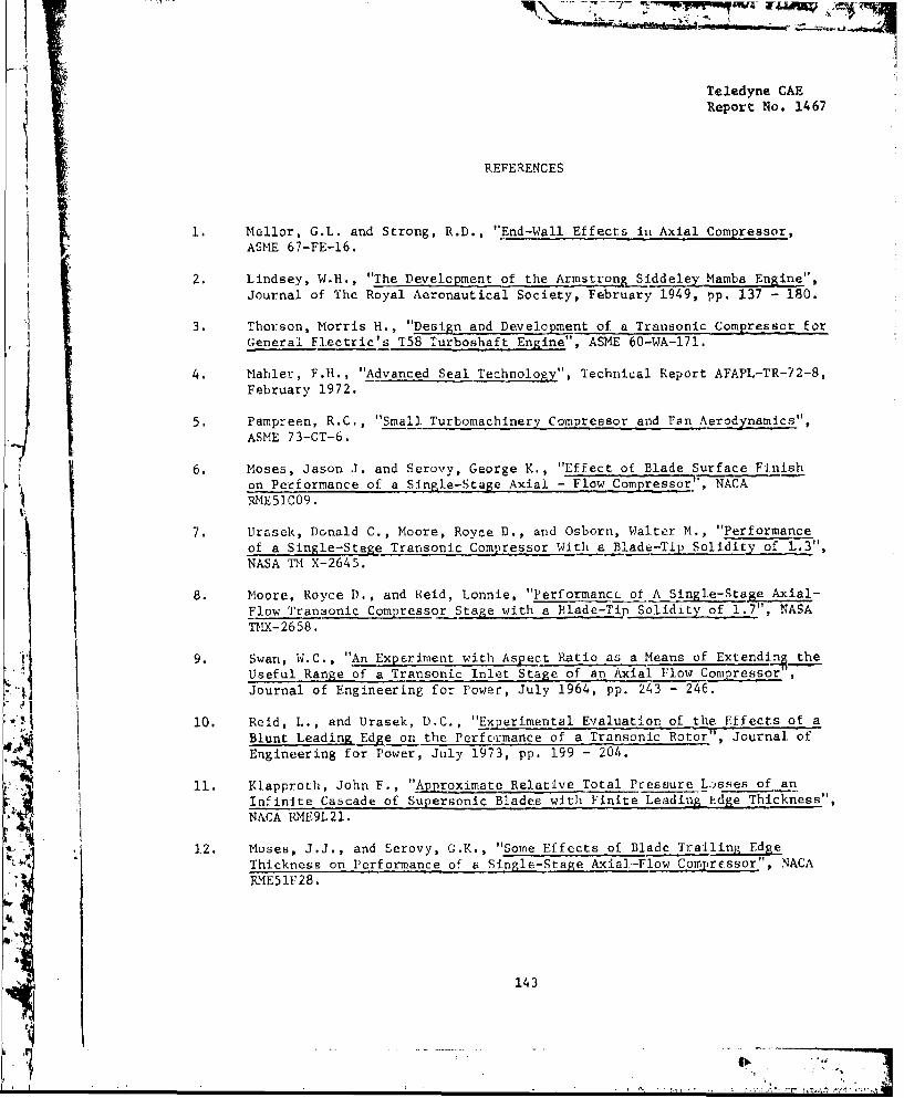
A
Teledyne CAEReport No. 1467
REFERENCES
1. Mellor, G.L. and Strong, R.D., "End-Wall Effects in Axial Compressor,ASME 67-FE-16.
2. Lindsey, W.H., "The Development of the Armstrong Siddeley Mamba Engine",Journal of The Royal Aeronautical Society, February 1949, pp. 137 - 180.
3. Thorson, Morris H., "Design and Development of a Transonic Compressor forGeneral Electric's T58 Turboshaft Engine", ASME 60-WA-171.
4. Mahler, F.H., "Advanced Seal Technology", Technical Report AFAPL-TR-72-8,February 1972.
5. Pampreen, R.C., "Small Turbomachinery Compressor and Fan Aerodynamics',
ASME 73-GT-6.
6. Moses, Jason J. and Serovy, George K,, "Effect of Blade Surface Finishon Performance of a Single-Stage Axial - Flow Compressor', NACARME51CO9.
7. Urasek, Donald C., Moore, Royce D., and Osborn, Walter M., "Performanceof a Single-Stage Transonic Compressor With a Blade-Tip Solidity of L.3",NASA TM X-2645.
8. Moore, Royce D., and Reid, Lonnie, "PerformancL of A Single-Stage Axial-Flow Transonic Compressor Stage with a Blade-Tip Solidity of 1.7", NASATMX-2658.
9. Swan, W.C., "An Experiment with Aspect Ratio as a Means of Extending theUseful Range of a Transonic Inlet Stage of an Axial Flow Compres
SjJournal of Engineering for Power, July 1964, pp. 243 - 246.
10. Reid, L., and Urasek, D.C., "Experimental Evaluation of the Effects of aBlunt Leading Edge on the Performance of a Transonic Rotor", Journal ofEngineering for Power, July 1973, pp. 199 - 204.
11. Klapproth, John F., "Approximate Relative Total Pressure Losses of anInfinite Cascade of Supersonic Blades with Finite Leading hdge Thickness",
NACA RME9L21.
1.2. Moses, J.J., and Serovy, G.K., "Some Effects of Blade Trailing EdgeThickness on Performance of a Single-Stage Axial-Flow Compressor", NACARME5lF28.
143
S,1

Teledyne CAEReport No. 1467
REFERENCES (continued)
13. Northern Research and Engineering Corporation, "Axial-Flow CompressorComputing System, Volume 1: Basic Theory", Report No. 1110-1, October24, 1.966.
14. "Aerodynamic Design of Axial-Flow Compressors", Volume II, 1 August 1956,by members of the Compressor and Turbine Research Division - Lewis FlightPropulsion Laboratory.
15.Deleted.
1 Deleted.
17, Lakshminarayana, B., "Effects of Inlet Temperature Gradients on Turbo-machinery Pertormance", ASME Paper No. 74-GT-57, April 1974.
18. AFAPL-TR-69-92, Volume I.
19. Anderson, Richard H., et al, "Models and Methodolo&Z for Life Cycle Costand Test and Evaluation". Anales: Office of the Assistant for StudySupport, Kirtland Air Force Base, New Mexico, July 1973, AD-782 182.
20. Paulson, R.M., et al, "Using Logistics Models in System Design and EarlySupport Planning," a report prepared for USAF Project Rand; Rand, SantaMonica, California. Report No. R-550-PR; February 1971.
21. Bierman, H., Jr., Bounne, C., and Hausman, W., "Quantitative Analysis forBusiness Decisions" KR [IaLU V. LLV.iLV, ILLU , LU_-L.W..U. LLJ --LLVJ^n,
22. Deleted.
23. Deleted.
144F". , ~'ALl lJ CI: -