Embed Size (px)
Citation preview
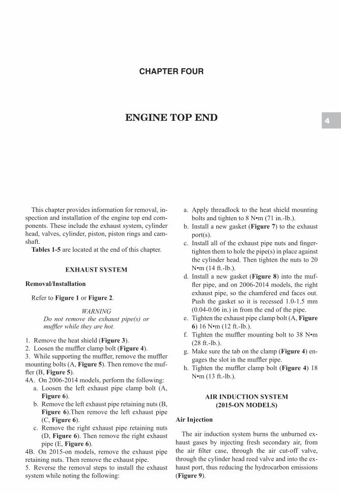
chapter four
engine top end 4
This chapter provides information for removal, in-spection and installation of the engine top end com-ponents. These include the exhaust system, cylinder head, valves, cylinder, piston, piston rings and cam-shaft.
Tables 1-5 are located at the end of this chapter.
EXHAUST SYSTEM
Removal/Installation
Refer to Figure 1 or Figure 2.
WARNINGDo not remove the exhaust pipe(s) or muffler while they are hot.
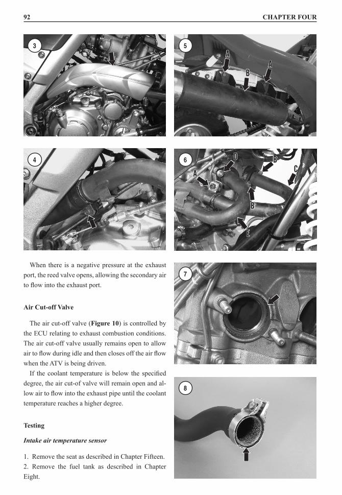
1. Remove the heat shield (Figure 3).2. Loosen the muffler clamp bolt (Figure 4).3. While supporting the muffler, remove the muffler mounting bolts (A, Figure 5). Then remove the muf-fler (B, Figure 5).4A. On 2006-2014 models, perform the following:
a. Loosen the left exhaust pipe clamp bolt (A, Figure 6).
b. Remove the left exhaust pipe retaining nuts (B, Figure 6).Then remove the left exhaust pipe (C, Figure 6).
c. Remove the right exhaust pipe retaining nuts (D, Figure 6). Then remove the right exhaust pipe (E, Figure 6).
4B. On 2015-on models, remove the exhaust pipe retaining nuts. Then remove the exhaust pipe.5. Reverse the removal steps to install the exhaust system while noting the following:
a. Apply threadlock to the heat shield mounting bolts and tighten to 8 N•m (71 in.-lb.).
b. Install a new gasket (Figure 7) to the exhaust port(s).
c. Install all of the exhaust pipe nuts and finger-tighten them to hole the pipe(s) in place against the cylinder head. Then tighten the nuts to 20 N•m (14 ft.-lb.).
d. Install a new gasket (Figure 8) into the muf-fler pipe, and on 2006-2014 models, the right exhaust pipe, so the chamfered end faces out. Push the gasket so it is recessed 1.0-1.5 mm (0.04-0.06 in.) in from the end of the pipe.
e. Tighten the exhaust pipe clamp bolt (A, Figure 6) 16 N•m (12 ft.-lb.).
f. Tighten the muffler mounting bolt to 38 N•m (28 ft.-lb.).
g. Make sure the tab on the clamp (Figure 4) en-gages the slot in the muffler pipe.
h. Tighten the muffler clamp bolt (Figure 4) 18 N•m (13 ft.-lb.).
AIR INDUCTION SYSTEM (2015-ON MODELS)
Air Injection
The air induction system burns the unburned ex-haust gases by injecting fresh secondary air, from the air filter case, through the air cut-off valve, through the cylinder head reed valve and into the ex-haust port, thus reducing the hydrocarbon emissions (Figure 9).
90 CHAPTER FOUR
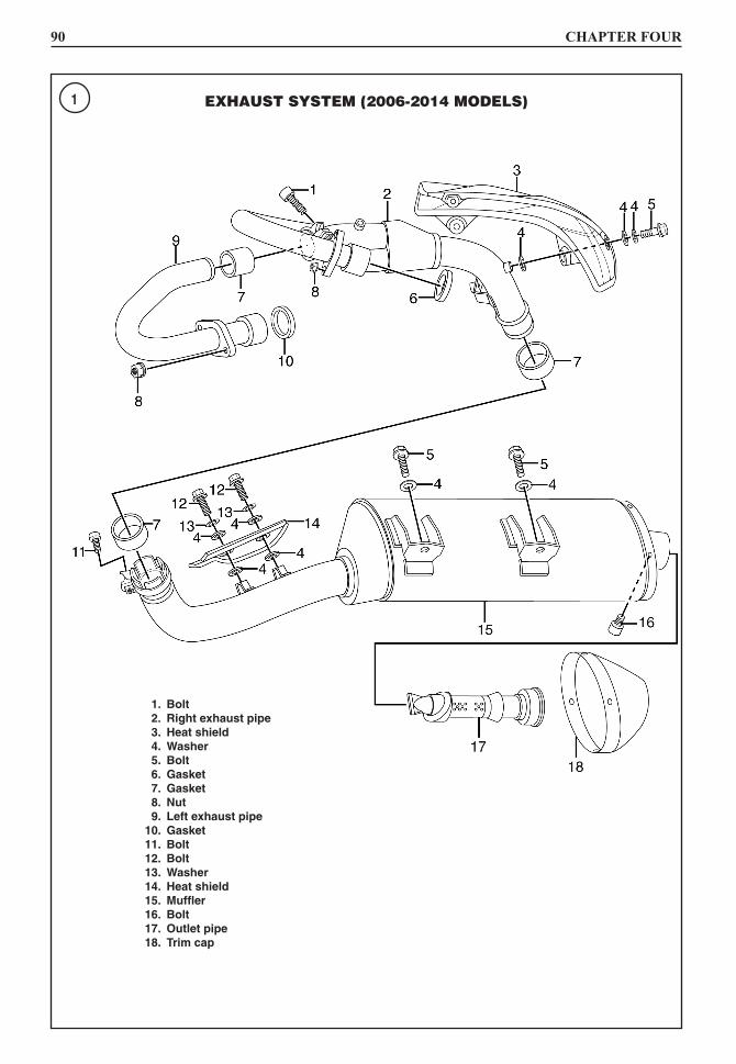
1 EXHAUST SYSTEM (2006-2014 MODELS)
1. Bolt 2. right exhaust pipe 3. heat shield 4. Washer 5. Bolt 6. Gasket 7. Gasket 8. Nut 9. Left exhaust pipe 10. Gasket 11. Bolt 12. Bolt 13. Washer 14. heat shield 15. Muffler 16. Bolt 17. outlet pipe 18. trim cap
4
ENGINE TOP END 91
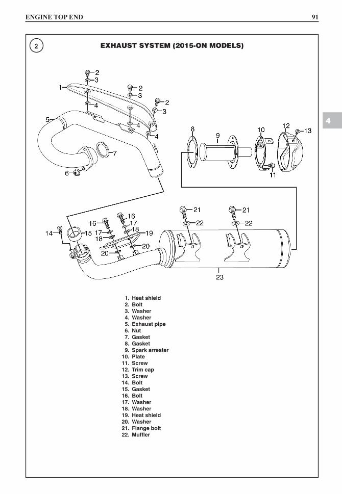
2 EXHAUST SYSTEM (2015-ON MODELS)
1. heat shield 2. Bolt 3. Washer 4. Washer 5. exhaust pipe 6. Nut 7. Gasket 8. Gasket 9. Spark arrester 10. plate 11. Screw 12. trim cap 13. Screw 14. Bolt 15. Gasket 16. Bolt 17. Washer 18. Washer 19. heat shield 20. Washer 21. flange bolt 22. Muffler
92 CHAPTER FOUR
When there is a negative pressure at the exhaust port, the reed valve opens, allowing the secondary air to flow into the exhaust port.
Air Cut-off Valve
The air cut-off valve (Figure 10) is controlled by the ECU relating to exhaust combustion conditions. The air cut-off valve usually remains open to allow air to flow during idle and then closes off the air flow when the ATV is being driven.If the coolant temperature is below the specified
degree, the air cut-of valve will remain open and al-low air to flow into the exhaust pipe until the coolant temperature reaches a higher degree.
Testing
Intake air temperature sensor
1. Remove the seat as described in Chapter Fifteen.2. Remove the fuel tank as described in Chapter Eight.
3
4
5
BA
A
6
A CD B
B
E
7
8

Copyright of Yamaha Raptor 700R, 2006-2016 is the property of Haynes North America, Inc.and its content may not be copied or emailed to multiple sites or posted to a listserv withoutthe copyright holder's express written permission. However, users may print, download, oremail articles for individual use.