Embed Size (px)
Citation preview
Engineer Training
XL1200 Electric
Confidential 2
Engineer Training
XL1200 Electric
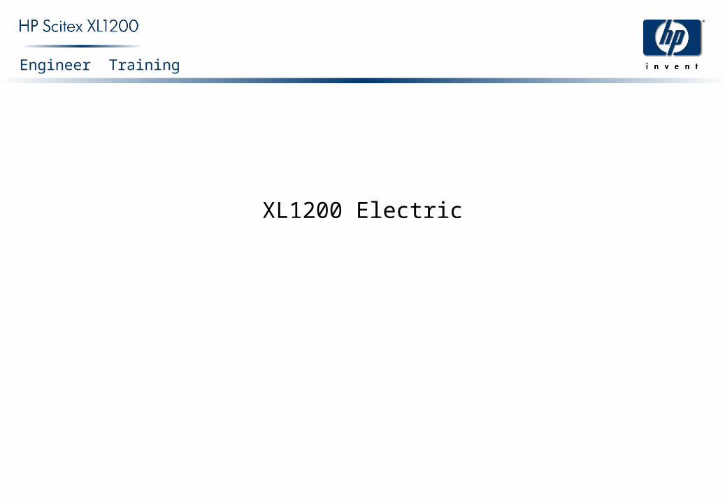
MonitorC
om
pu
ter
40 VPowerSupply
24 VPowerSupply
220 V
220V
220 V
220 V
220 V
220 V
220 V
220 V
220VPo
we
r S
plit
er
MotorCollector
Infra Red Heating System
Dri
ver
Dri
ver
Dri
ver
Dri
ver
Motor Motor
MotorMotorMotionController
EmergencyContactor
24 V in
24 V out
Ma
in E
lect
ric
Ca
bin
et
Block Diagram
Confidential 3
Engineer Training
XL1200 Electric
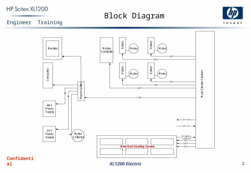
Open Cabin
Confidential 4
Engineer Training
XL1200 Electric
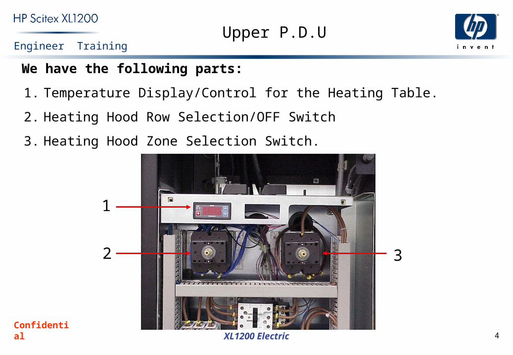
Upper P.D.U
We have the following parts:
1. Temperature Display/Control for the Heating Table.
2. Heating Hood Row Selection/OFF Switch
3. Heating Hood Zone Selection Switch.
1
2 3
Confidential 5
Engineer Training
XL1200 Electric
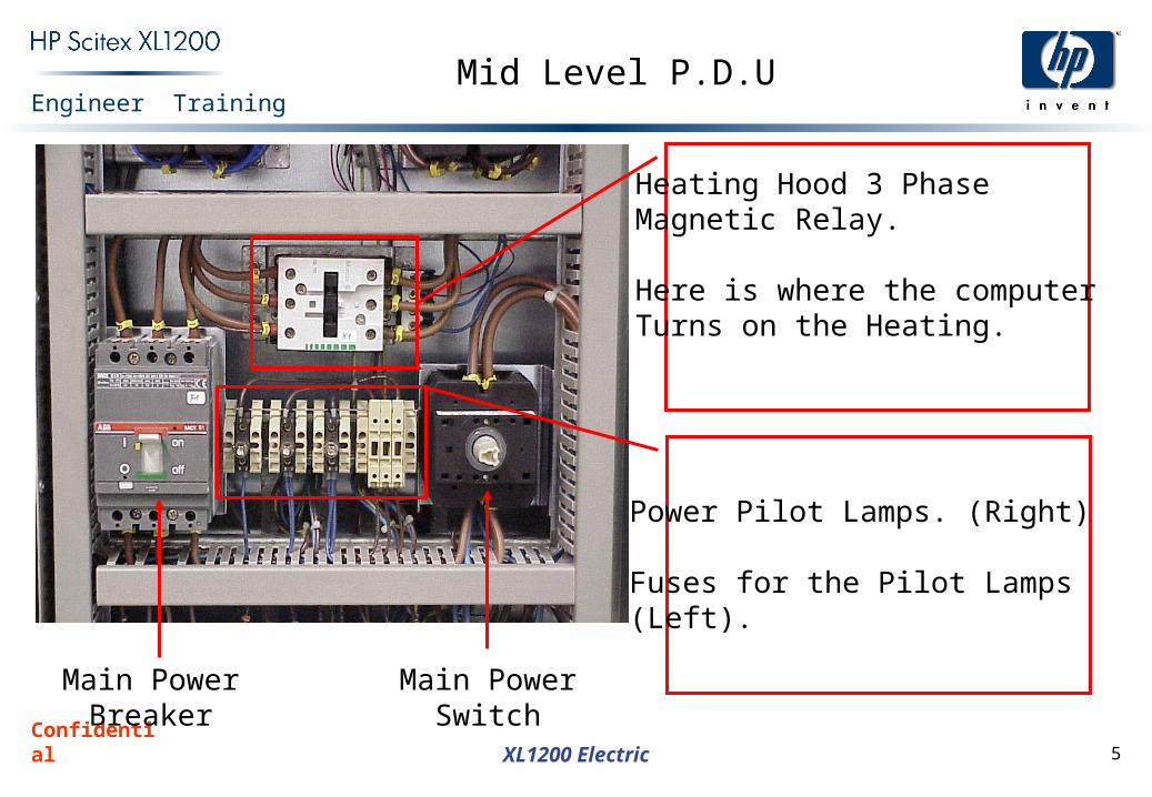
Mid Level P.D.U
Heating Hood 3 Phase Magnetic Relay.
Here is where the computerTurns on the Heating.
Power Pilot Lamps. (Right)
Fuses for the Pilot Lamps(Left).
Main PowerBreaker
Main PowerSwitch

Confidential 6
Engineer Training
XL1200 Electric
Lower Level P.D.U
Main PowerFilter
Surge/SpikeSuppressor
CircuitSafety SystemRelay
Heating TableRelay
UPS/MainSelector Switch
Confidential 7
Engineer Training
XL1200 Electric
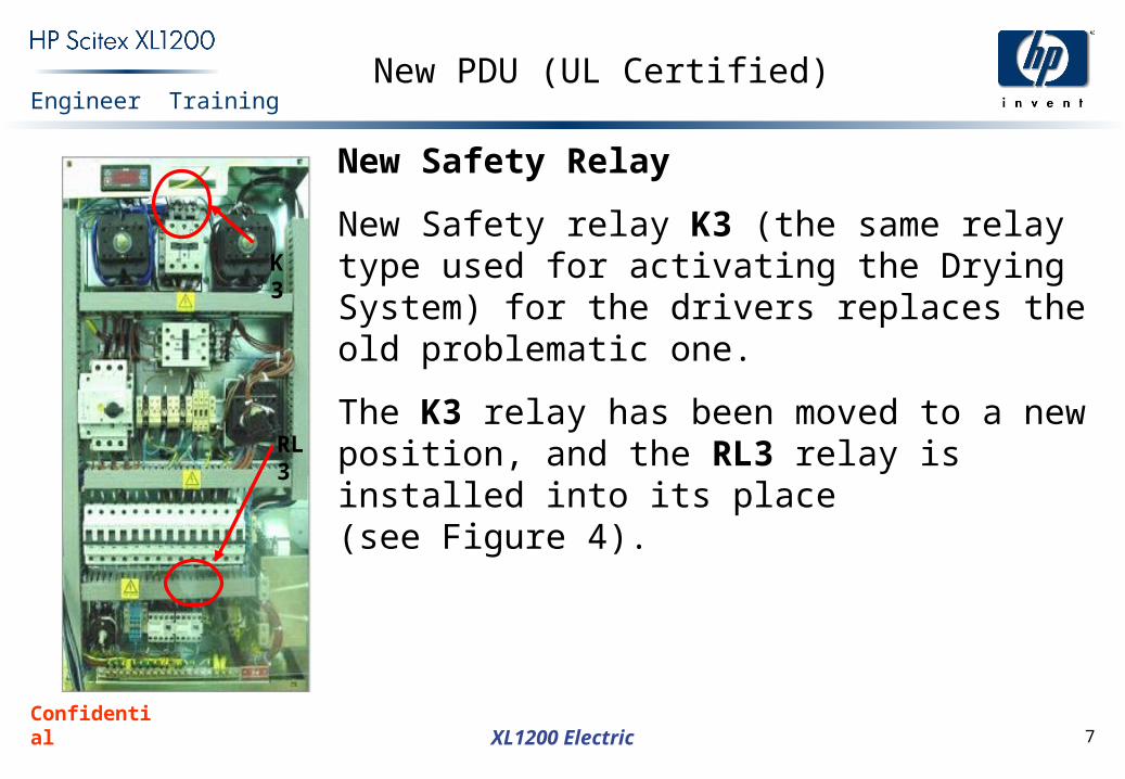
New PDU (UL Certified)
New Safety Relay
New Safety relay K3 (the same relay type used for activating the Drying System) for the drivers replaces the old problematic one.
The K3 relay has been moved to a new position, and the RL3 relay is installed into its place(see Figure 4).
K3
RL3
Confidential 8
Engineer Training
XL1200 Electric
New PDU (UL Certified)
Confidential 9
Engineer Training
XL1200 Electric
New PDU (UL Certified)
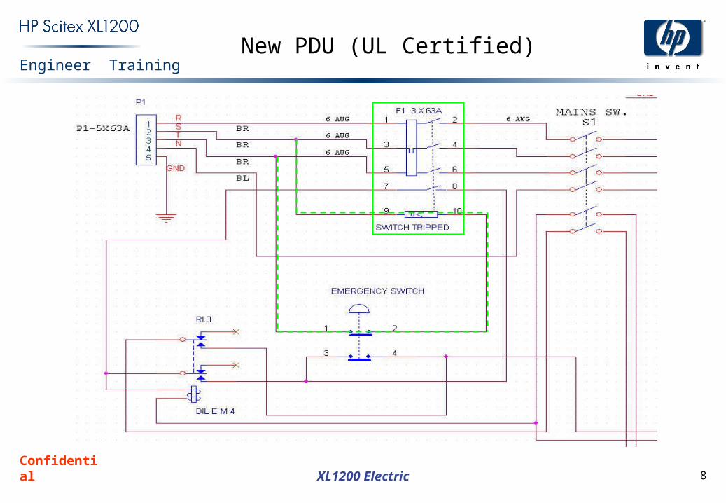
New Main 3-phase Circuit Breaker
The main Circuit Breaker F1 (see green line) includes the Switch Tripped mechanism (terminals 9,10). The two phases are connected (see dashed green line) via the Emergency Switch.
When the Switch Tripped is powered, the F1 contacts are closed and the machine is connected to the power line.
When the Emergency Switch is pressed, the Switch Tripped is powered off and the F1 contacts are opened; i.e. the machine is disconnected from the power line.
Confidential 10
Engineer Training
XL1200 Electric
New PDU (UL Certified)
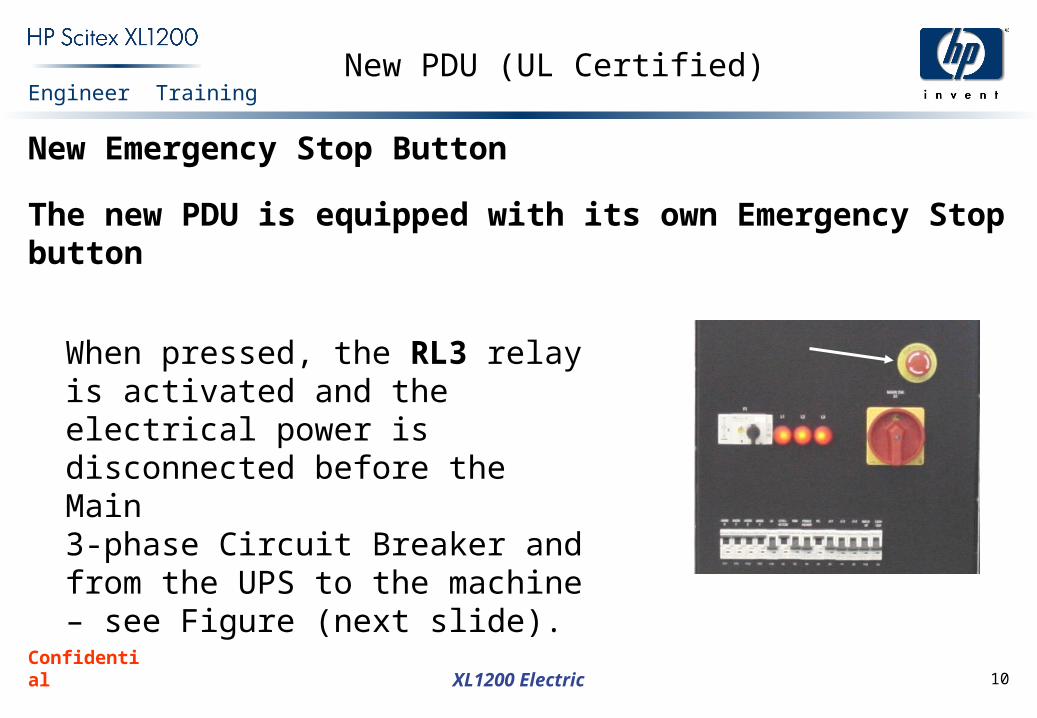
New Emergency Stop Button
The new PDU is equipped with its own Emergency Stop button
When pressed, the RL3 relay is activated and the electrical power is disconnected before the Main3-phase Circuit Breaker and from the UPS to the machine – see Figure (next slide).
Confidential 11
Engineer Training
XL1200 Electric
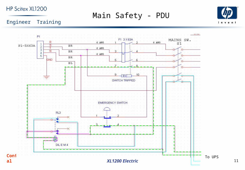
Main Safety - PDU
To UPS
Confidential 12
Engineer Training
XL1200 Electric
Main Safety - PDU
The green dash line marks the circuit UPS Emergency Switch RL3 coil UPS. When the Emergency Switch is pressed, this circuit is opened.
The cyan dot line specifies the circuitUPS RL3 contacts Drivers Left Cabinet (PC, Power Supplies) UPS. When the Emergency Switch is pressed, this circuit is opened.
The magenta dot line specifies the self-sustain loop for holding the RL3 powered in case of general electric failure(i.e. Switch Tripped is not powered and the green circuit is opened).
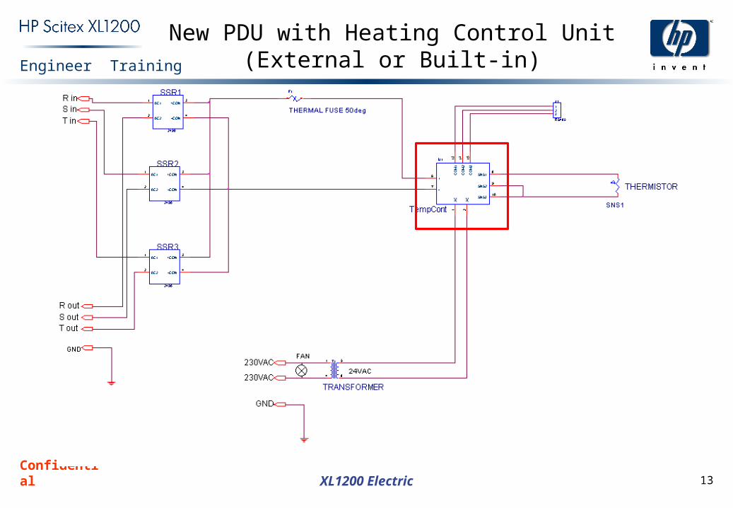
Confidential 13
Engineer Training
XL1200 Electric
New PDU with Heating Control Unit (External or Built-in)