Embed Size (px)
Citation preview

© 2016 Halliburton. All rights reserved.
Engineered Perforating Design for Hydraulic Fracture Stimulation
SLAP 16-19
Martin Schoener Scott, Halliburton
2© 2016 Halliburton. All rights reserved.
Engineered Perforating Design for Hydraulic Fracture Stimulation
SLAP-16-19
INTRODUCTION
Slide 2
� Minimizing costs while maximizing the profitability of pumpdown plug and perforating.
• Analyzing consistent hole charge (CHC) attributes (rate and pressure) reveals
the true value.
3© 2016 Halliburton. All rights reserved.
Engineered Perforating Design for Hydraulic Fracture Stimulation
SLAP-16-19
INTRODUCTION
OBJECTIVES
� Evaluate three charge designs and there effects on fluid volumes,
rates, and proppant placement
amounts.
• All charges must be industry standard technology
CHALLENGES
• Located well data that used multiple charge designs in one well for the closest charge to charge comparison.
• Quantify the charge effects and the monetary gains
Slide 3
4© 2016 Halliburton. All rights reserved.
Engineered Perforating Design for Hydraulic Fracture Stimulation
SLAP-16-19
Charge Methodology
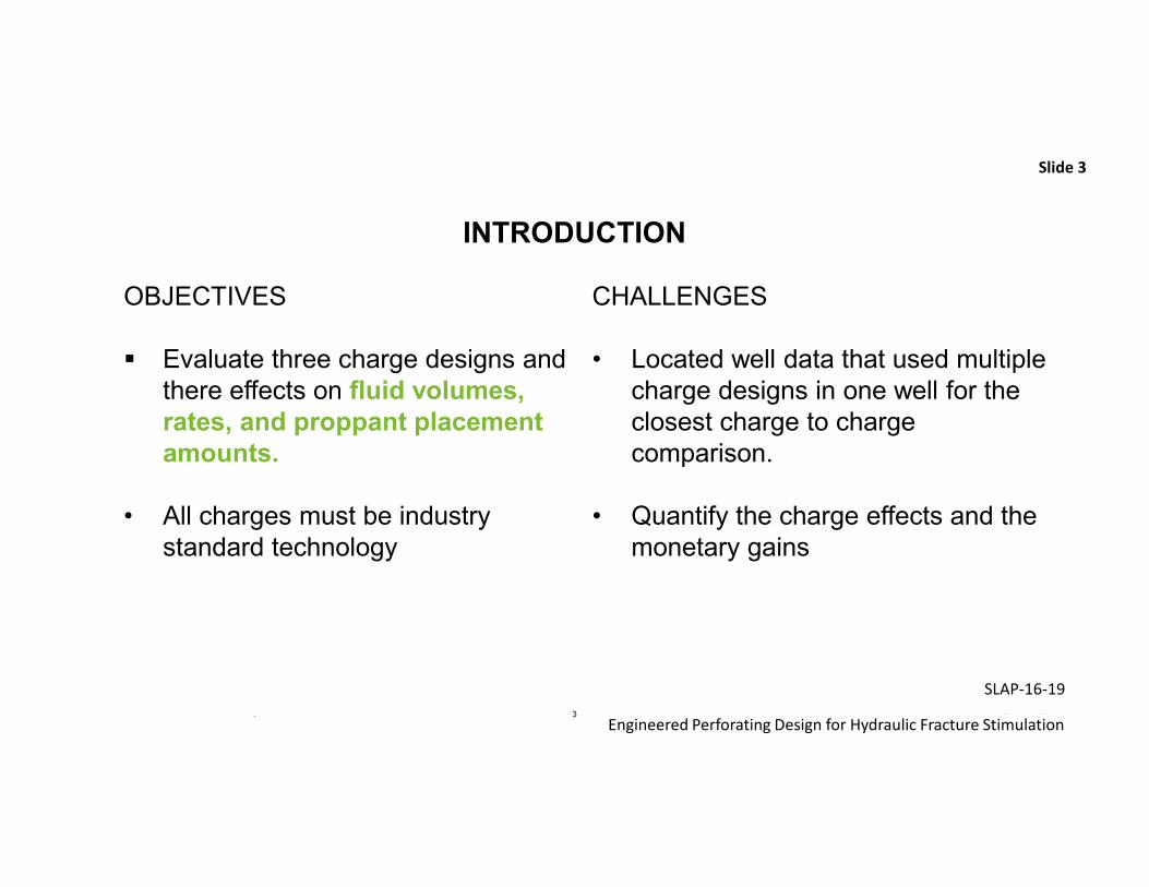
• Deep Penetrating charges focus on greatest penetration depth with little regard for hole size variances
• Good Hole charges achieve the larger average EHD only when gun is eccentered (reduce gun to casing clearance)
• Constant Hole Charges is designed for reduced EHD variance while balancing perforation depth for unconventional completions
Slide 4
5© 2016 Halliburton. All rights reserved.
Engineered Perforating Design for Hydraulic Fracture Stimulation
SLAP-16-19
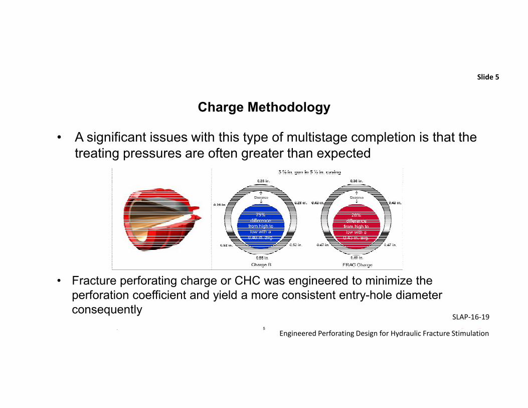
Charge Methodology
• A significant issues with this type of multistage completion is that the treating pressures are often greater than expected
Slide 5
• Fracture perforating charge or CHC was engineered to minimize the perforation coefficient and yield a more consistent entry-hole diameter consequently
6© 2016 Halliburton. All rights reserved.
Engineered Perforating Design for Hydraulic Fracture Stimulation
SLAP-16-19
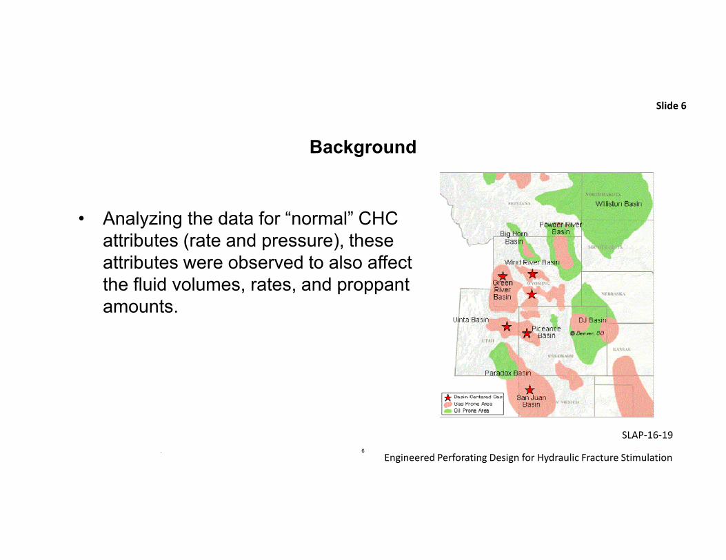
Background
• Analyzing the data for “normal” CHC attributes (rate and pressure), these attributes were observed to also affect the fluid volumes, rates, and proppant amounts.
Slide 6
7© 2016 Halliburton. All rights reserved.
Engineered Perforating Design for Hydraulic Fracture Stimulation
SLAP-16-19
Case Study
• A total of 17 wells were shot with CHC.
o Ten wells were finished that could provide
some comparison to SDP charges shot in
adjacent stages, wells, or pads.
o Seven wells not used as a charge
comparison.� Two wells not used because operator had
previously only done only sleeves.
� Four wells had too many variables changed
between the SDP charges and CHC pads.
� One well was a lone hybrid and had numerous
issues/changes on the PE side throughout the
completion.
Slide 7
• Nine of the ten wells used for comparison indicated less fluid used on the CHC stages, as
compared to either the same well, non-CHC stages, or prior trends.
The following lists summarize the findings of the field study.
8© 2016 Halliburton. All rights reserved.
Engineered Perforating Design for Hydraulic Fracture Stimulation
SLAP-16-19
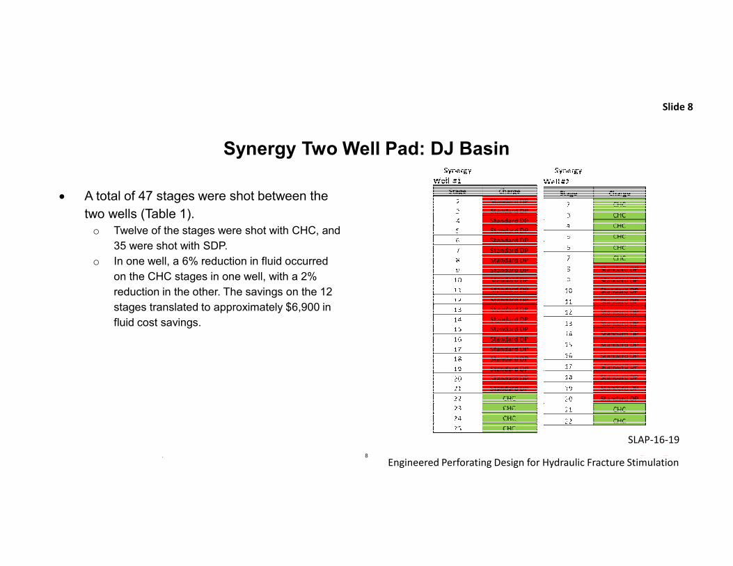
Synergy Two Well Pad: DJ Basin
• A total of 47 stages were shot between the
two wells (Table 1). o Twelve of the stages were shot with CHC, and
35 were shot with SDP.
o In one well, a 6% reduction in fluid occurred
on the CHC stages in one well, with a 2%
reduction in the other. The savings on the 12
stages translated to approximately $6,900 in
fluid cost savings.
Slide 8
9© 2016 Halliburton. All rights reserved.
Engineered Perforating Design for Hydraulic Fracture Stimulation
SLAP-16-19
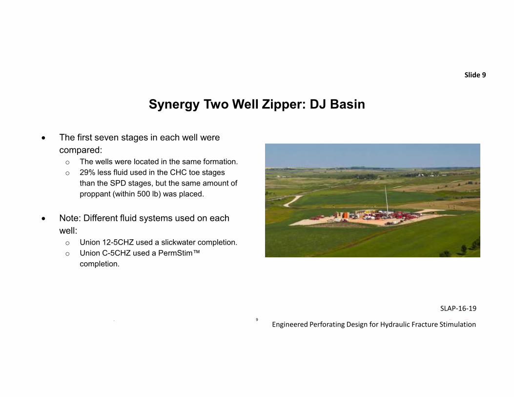
Synergy Two Well Zipper: DJ Basin
• The first seven stages in each well were
compared:o The wells were located in the same formation.
o 29% less fluid used in the CHC toe stages
than the SPD stages, but the same amount of
proppant (within 500 lb) was placed.
• Note: Different fluid systems used on each
well: o Union 12-5CHZ used a slickwater completion.
o Union C-5CHZ used a PermStim™
completion.
Slide 9
10© 2016 Halliburton. All rights reserved.
Engineered Perforating Design for Hydraulic Fracture Stimulation
SLAP-16-19
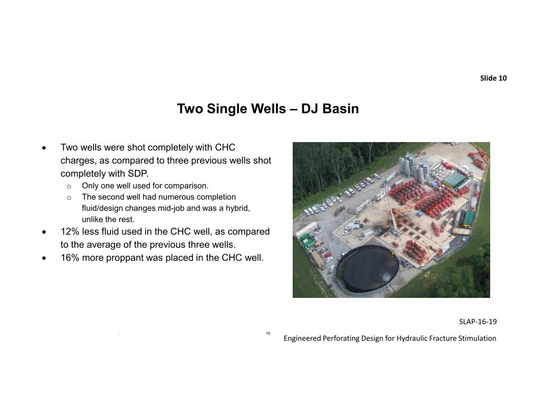
Two Single Wells – DJ Basin
• Two wells were shot completely with CHC
charges, as compared to three previous wells shot
completely with SDP.o Only one well used for comparison.
o The second well had numerous completion
fluid/design changes mid-job and was a hybrid,
unlike the rest.
• 12% less fluid used in the CHC well, as compared
to the average of the previous three wells.
• 16% more proppant was placed in the CHC well.
Slide 10
11© 2016 Halliburton. All rights reserved.
Engineered Perforating Design for Hydraulic Fracture Stimulation
SLAP-16-19
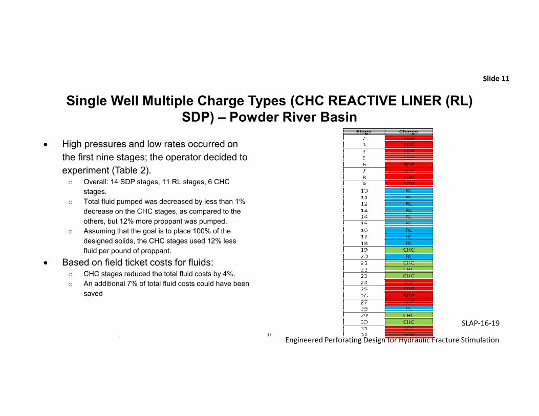
Single Well Multiple Charge Types (CHC REACTIVE LINER (RL)
SDP) – Powder River Basin
• High pressures and low rates occurred on
the first nine stages; the operator decided to
experiment (Table 2).o Overall: 14 SDP stages, 11 RL stages, 6 CHC
stages.
o Total fluid pumped was decreased by less than 1%
decrease on the CHC stages, as compared to the
others, but 12% more proppant was pumped.
o Assuming that the goal is to place 100% of the
designed solids, the CHC stages used 12% less
fluid per pound of proppant.
• Based on field ticket costs for fluids:o CHC stages reduced the total fluid costs by 4%.
o An additional 7% of total fluid costs could have been
saved
Slide 11
12© 2016 Halliburton. All rights reserved.
Engineered Perforating Design for Hydraulic Fracture Stimulation
SLAP-16-19
Additional Trials
• Single well (Powder River basin): 6% less
fluid was pumped per pound of proppant.
• 4 CHC wells vs. 5 SDP wells (Bakken):
7% less fluid was pumped per pound of
proppant.
• Single well (Powder River basin): 8%
more fluid pumped per pound of proppant
on CHC stages
Slide 12
13© 2016 Halliburton. All rights reserved.
Engineered Perforating Design for Hydraulic Fracture Stimulation
SLAP-16-19
CONCLUSIONS
Although the percentages appear to be small, the use of CHC has a positive long-term effect on the maintenance requirements and efficiencies of the frac crew. In addition, less fluid required reduces the costs for the operator.
Slide 13
14© 2016 Halliburton. All rights reserved.
Engineered Perforating Design for Hydraulic Fracture Stimulation
SLAP-16-19
Acknowledgements / Thank You / Questions
We would like to thank AAPG for allowing us the opportunity to present a new way to understand value of the right Perforating Technology .
The authors would like to thank the operators for capturing and analyzing the data and Halliburton for allowing us to put this document together.
Slide 14
15© 2016 Halliburton. All rights reserved.
Engineered Perforating Design for Hydraulic Fracture Stimulation
SLAP-16-19
QUESTIONS? THANK YOU!
2016 LATIN AMERICA PERFORATING SYMPOSIUM, BUENOS AIRES