Embed Size (px)
Citation preview
FA
BR
I-VA
LVE
® Lin
ed
Knif
e G
ate
Va
lve Figure 37
Revision 2
C LEngineered Valves
Pressure/Temperature Rating - psi (bar)
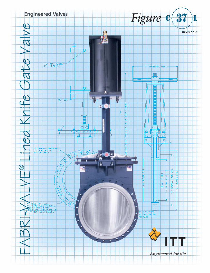
he Fabri-Valve C37L offers the corrosion resistanceof a stainless steel lining with the economy of acast iron body. The body and chest are lined with a choice of 304, 316 or 317L stainless steel. Fabri-Valve lined valves feature fully supported liners that are vacuum leak tested during manufacture.Meets or exceeds specifications MSS-SP-81 andTappi 405-8.
Fabri-Valve® C37L Lined Knife Gate Valve
SpecificationsSize Range Pressure Rating30" & 36" 150 psi (10.3 bar) CWP (cold
working pressure)
Temperature Rating450°F (232°C). Service temperatures above 400°F (204°C)require high temperature fasteners. Specify service tempera-ture on paperwork.
Flange DrillingANSI 125/150
TestingEvery Fabri-Valve Figure C37L valve is fully tested prior toshipment. Testing includes a body shell test, a seat test, anda cycling test to insure proper functioning of moving parts.Additional testing is also available. Please let us know yourrequirements.
Standard Shell test:• Hydro test at 1.5 times the rated CWP (cold working
pressure) – Zero allowable leakage
Standard Seat test:• Metal Seat: Hydro test at 40 psi (2.8 bar) and at
the rated CWP
• Resilient Seat: Hydro test at 15 psi (1 bar) and rated CWP
Shutoff PerformanceMetal Seat• Single integral metal seat
30" & 36" 60cc / minute / inch of valve sizeResilient Seat• Single “D” ring Zero leakage all sizes
The table below is the Maximum Pressure Temperature Ratings forthe metallic components only. When checking pressure/temperatureratings, check the temperature rating and chemical compatibility of the packing material, and if applicable, the resilient seat material. In a majority of knife gate valve designs, the temperature limit orthe chemical compatibility of the seat and/or packing material determines the practical pressure/temperature limitations.
Flow Coefficients
The Cv values below represent U.S. gallons per minute 60°F waterthrough a 100% open valve at a pressure drop of 1 psi. The metricequivalent, Kv, is the flow of water at +16°C through the valve incubic meters per hour at a pressure drop of 1 kg/cm2. To convertCv to Kv, multiply the Cv by 0.8569.
Pressure/Temperature RatingsT
Cv Ratings
150 66 150 (10.3)200 93 141 (9.7)250 121 132 (9.1)300 149 122 (8.4)350 177 113 (7.8)400 204 104 (7.2)450 232 94 (6.5)
Metal Cv
30 750 53,950 54,450 36 900 77,800 79,600
D-Ring Cv
Materials of Construction
Part Material
Body, Chest and Flanges One piece cast iron body, chest and flanges lined with 304, 316 or 317L stainless steel. Flanges have smooth stainless steel raised faces. .
Seat Stainless steel or optional "D" ringGate Same grade stainless steel as liner, finished to 63 RMSYoke Carbon steelYoke Fasteners Plated steelStem 304 Stainless steelStem Nut Acid resistant bronzeLubrication Fitting Plated steelPacking Acrylic/PTFE/SiliconePacking Follower Carbon steel with plated steel boltingHandwheel Cast ironHandwheel Nut Malleable ironTab Washer Stainless steel
Inches DN Valve Size
Temp°F °C
Available Options
• “D” Ring Seat• Epoxy Coating• Thru Drilled Flanges• V-Port • Locking Devices• Live Loaded Packing• Self-Supporting Yoke• Bevel Gear • Centerline Buttons
• Backing Rings • Deflection Cones • Chainwheels • Cylinder Actuators • Electric Actuators • Ratchet • Extended Stems • Gate Support Strips • Rod Boots
-2-
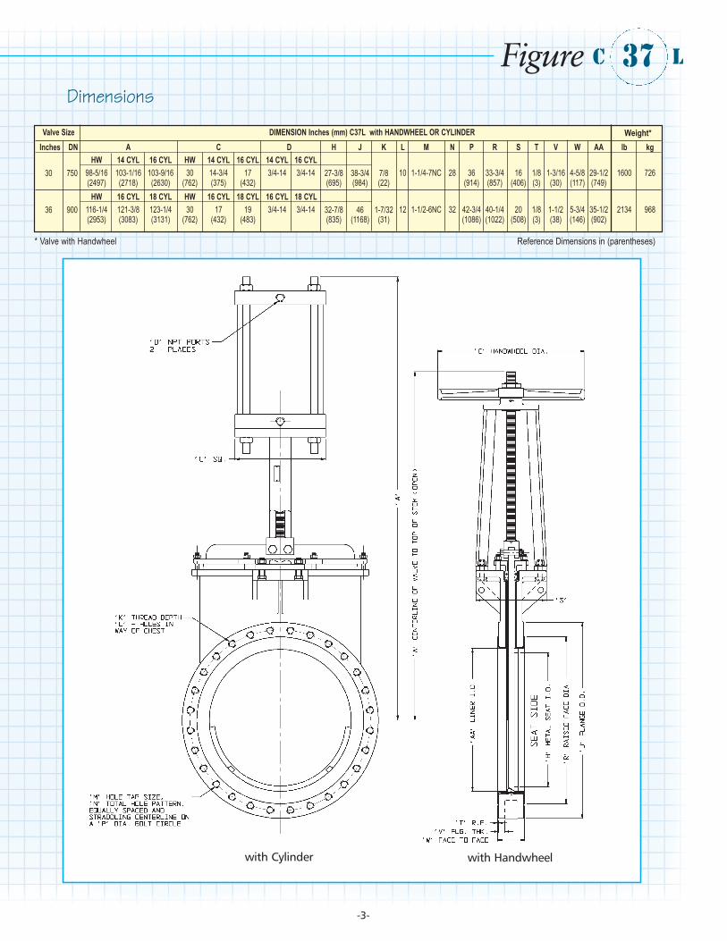
Dimensions
Valve Size DIMENSION Inches (mm) C37L with HANDWHEEL OR CYLINDERInches DN A C D H J K L M N P R S T V W AA lb kg
HW 14 CYL 16 CYL HW 14 CYL 16 CYL 14 CYL 16 CYL30 750 98-5/16 103-1/16 103-9/16 30 14-3/4 17 3/4-14 3/4-14 27-3/8 38-3/4 7/8 10 1-1/4-7NC 28 36 33-3/4 16 1/8 1-3/16 4-5/8 29-1/2 1600 726
(2497) (2718) (2630) (762) (375) (432) (695) (984) (22) (914) (857) (406) (3) (30) (117) (749)HW 16 CYL 18 CYL HW 16 CYL 18 CYL 16 CYL 18 CYL
36 900 116-1/4 121-3/8 123-1/4 30 17 19 3/4-14 3/4-14 32-7/8 46 1-7/32 12 1-1/2-6NC 32 42-3/4 40-1/4 20 1/8 1-1/2 5-3/4 35-1/2 2134 968(2953) (3083) (3131) (762) (432) (483) (835) (1168) (31) (1086) (1022) (508) (3) (38) (146) (902)
Figure 37C L
with Cylinder with Handwheel
Weight*
* Valve with Handwheel Reference Dimensions in (parentheses)
-3-
Engineered Valves
For more information contact:Engineered Valves 1110 Bankhead AvenueAmory, MS 38821 USAPhone: (800) 541-1849
(662) 256-7185 Fax: (662) 256-7932 Web site: www.engvalves.comE-mail: [email protected]
© 2007 ITT Corporation
-4-