Embed Size (px)
Citation preview
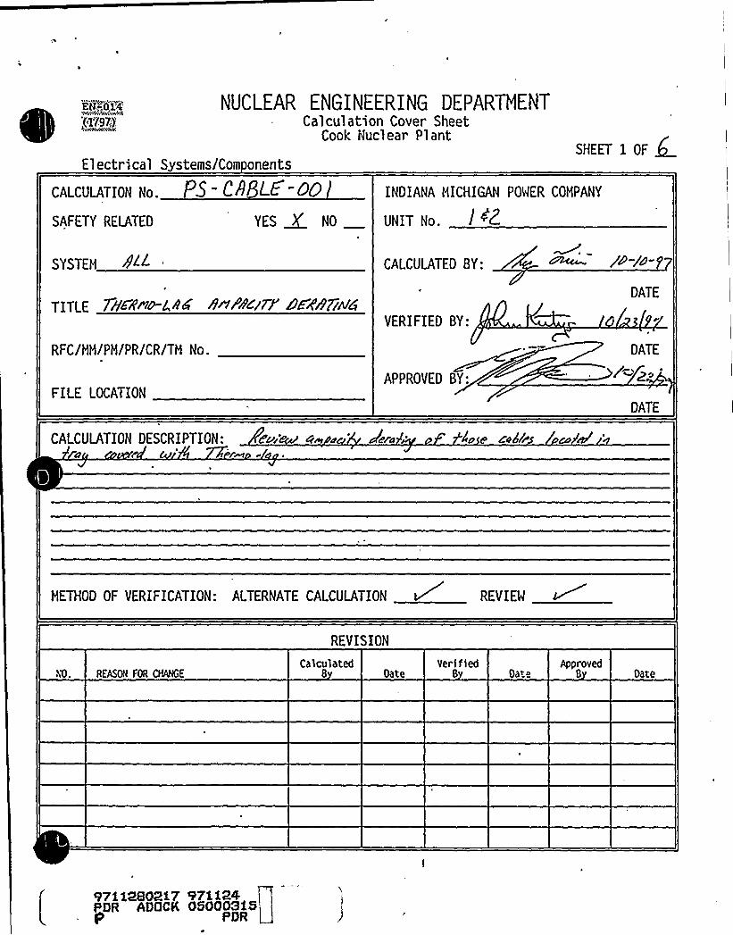
'(IV97).NUCLEAR ENGINEERING DEPARTHENT
Calculation Cover SheetCook Nuclear Plant
SHEET I OF QElectrical Systems/Com onents
CALCULATION No. P5 C8 LE -OO
SAFETY RELATED YES ~ NO
SYSTEM 8 "/
TITLE 7brs~~a~r R~Pa~ry'ZRazuua
RFC/MM/PM/PR/CR/TM No.
FILE LOCATION
INDIANA MICHIGAN POWER COMPANY
UNIT No. / ~Z
CALCULATED BY:
VERIFIED BY:
APPROVED BY:
gD-/o-p
DATE
DATE
DATE
CALCULATION DESCRIPTION: dvi'ern u 'lare 4o e sN8/r ou M
'ETHOO
OF YfRIFI CATION: ALTERNATE CALCULATION v REYIEW
REVISION
NO. REASON FOR CHANGECalculated
8 OateVerifled
8 OateApproved
8 Date
97ii2802i7 97ii24PDR ADOCK Q50003i5
PDR

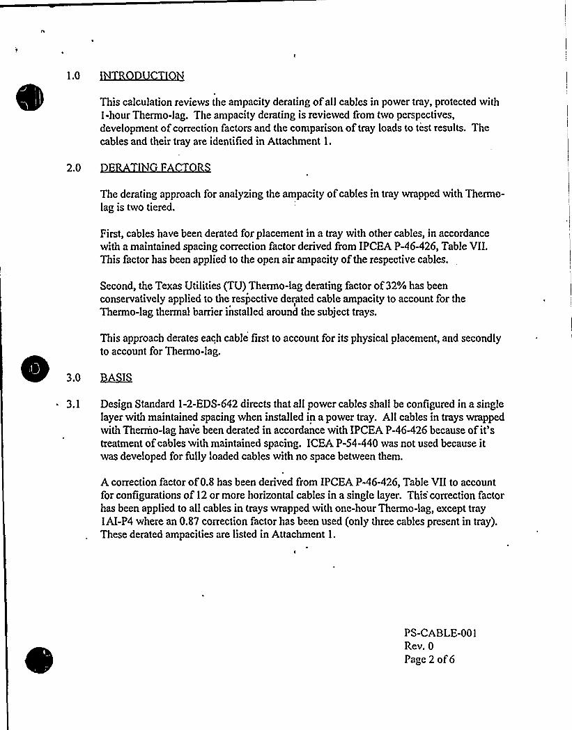
1.0
This calculation reviews the ampacity derating ofall cables in power tray, protected with1-hour Thermo-lag. The ampacity derating is reviewed from two perspectives,development ofcorrection factors and the comparison of tray loads to test results. Thecables and their tray are identified in Attachment l.
2.0 I F T
The derating approach for analyzing the ampacity ofcables in tray wrapped with Thermo-lag is two tiered.
First, cables have been derated for placement in a tray with other cables, in accordancewith a maintained spacing correction factor derived from IPCEA P-46-426, Table VII.This factor has been applied to the open air ampacity of the respective cables.
Second, the Texas Utilities (TU) Thermo-lag derating factor of32% has beenconservatively applied to the respective derated cable ampacity to account for theThermo-lag thermal barrier installed around the subject trays.
This approach derates each cable first to account for its physical placement, and secondlyto account for Thermo-lag.
3.0 ~A@
3.1 Design Standard 1-2-EDS-642 directs that all power cables shall be configured in a singlelayer with maintained spacing when installed in a power tray. Allcables in trays wrappedwith Thermo-lag have been derated in accordance with IPCEA P-46-426 because of it'treatment ofcables with maintained spacing. ICEA P-54-440 was not used because itwas developed for fully loaded cables with no space between them.
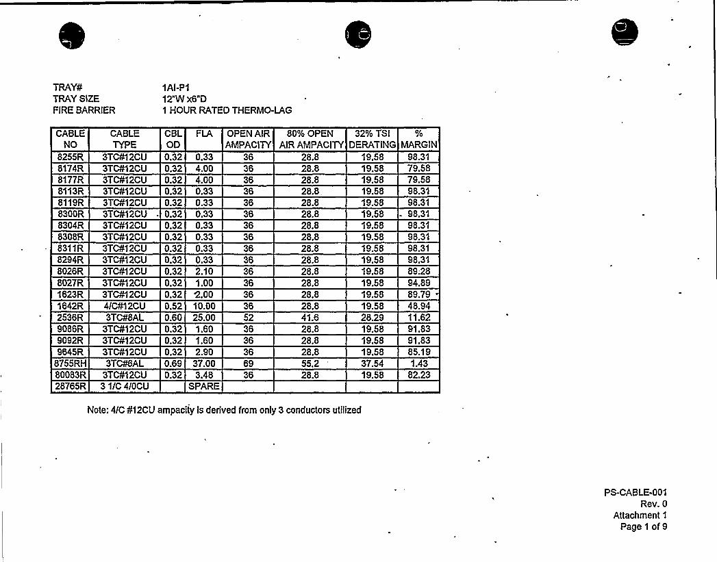
A correction factor of0.8 has been derived from IPCEA P-46-426, Table VII to accountfor configurations of 12 or more horizontal cables in a single layer. This'correction factorhas been applied to all cables in trays wrapped with one-hour Thermo-lag, except tray1AI-P4 where an 0.87 correction factor has been used (only three cables present in tray).These derated ampacities are listed in Attachment 1.
PS-CABLE-001Rev. 0
Page 2 of6
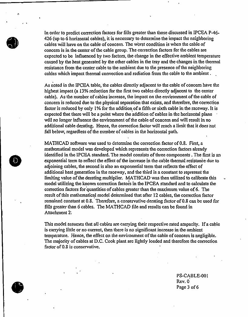
In order to predict correction factors for fillsgreater than those discussed in IPCEA P-46-426 (up to 6 horizontal cables), it is necessary to determine the impact the neighboringcables willhave on the cable ofconcern. The worst condition is when the cable ofconcern is in the center of the cable group. The correction factors for the cables are
expected to be influenced by two factors, the change in the effective ambient temperaturecaused by the heat generated by the other cables in the tray and the changes in the thermalresistance from the center cable to the ambient due to the presence of the neighboringcables which impact thermal convection and radiation from the cable to the ambient.
As noted in the IPCEA table, the cables directly adjacent to the cable ofconcern have thehighest impact (a 13% reduction for the first two cables directly adjacent to the centercable). As the number ofcables increase, the impact on the environment of the cable ofconcern is reduced due to the physical separation that exists, and therefore, the correctionfactor is reduced by only 1% for the addition ofa flAhor sixth cable in the raceway. It isexpected that there willbe a point where the addition ofcables in the horizontal planewillno longer influence the environment of the cable ofconcern and willresult in noadditional cable derating. Hence, the correction factor willreach a limitthat it does 'not
fall below, regardless of the number ofcables in the horizontal path.
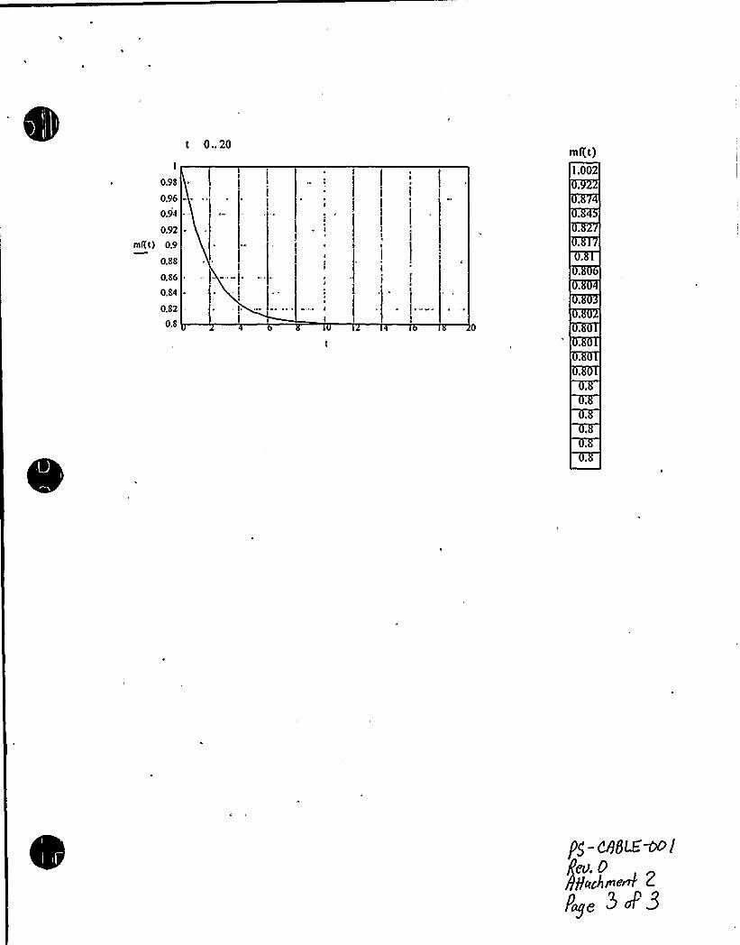
MATHCADsoftware was used to determine the correction factor of0.8. First, amathematical model was developed which represents the correction factors alreadyidentified in the IPCEA standard. The model consists of three components . The first is anexponential term to reflect the effect of the increase in the cable thermal resistance due toadjoining cables, the second is also an exponential term that reflects the effect ofadditional heat generation in the raceway, and the third is a constant to represent thelimitingvalue of the derating multiplier. MATHCADwas then utilized to calibrate thismodel utilizing the known correction factors in the IPCEA standard and to calculate thecorrection factors for quantities ofcables greater than the maximum value of6. Theresult of this mathematical model determined that after 12 cables, the correction factorremained constant at 0.8. Therefore, a conservative derating factor of0.8 can be used forfillsgreater than 6 cables. The MATHCADfile and results can be found inAttachment 2';
This model assumes that all cables are carrying their respective rated ampacity. Ifa cableis carrying little or no current, then there is no significant increase in the ambienttemperature. Hence, the effect on the environment of the cable ofconcern is negligible,The majority ofcables at D.C. Cook plant are lightly loaded and therefore the correctionfactor of0.8 is conservative.
PS-CABLE-001Rev. 0
Page 3 of6

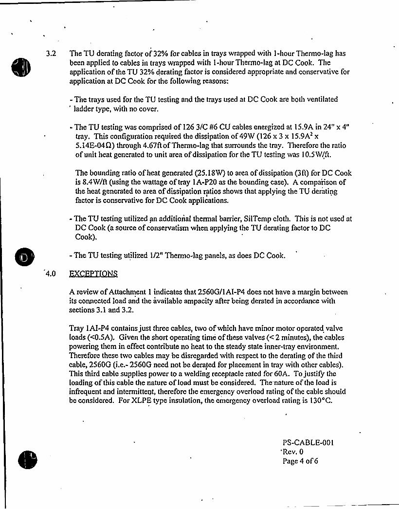
3.2 The TU derating factor of 32% for cables in trays wrapped with 1-hour Thermo-lag has
been applied to cables in trays wrapped with 1-hour Thermo-lag at DC Cook. Theapplication of the TU 32% derating factor is considered appropriate and conservative forapplication at DC Cook for the following reasons:
- The trays used for the TU testing and the trays used at DC Cook are both ventilated'adder type, with no cover.
- The TU testing was comprised of 126 3/C II6 CV cables energized at 15.9A in 24" x 4"
tray. This configuration required the dissipation of49W (126 x 3 x 15.9A2 x5.14E-04Q) through 4.67ft ofThermo-lag that surrounds the tray. Therefore the ratioofunit heat generated to unit area ofdissipation for the TU testing was 10.5W/ft.
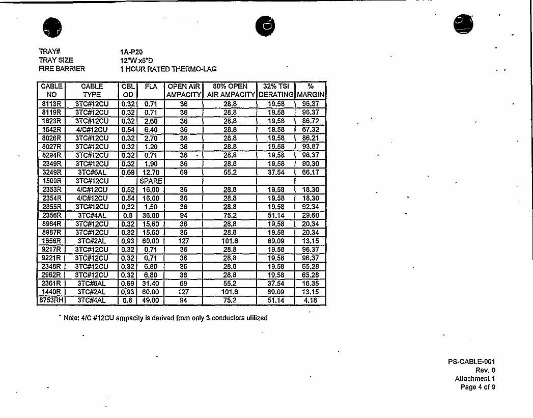
The bounding ratio ofheat generated (25.18W) to area ofdissipation (3ft) for DC Cookis 8.4W/ft (using the wattage of tray 1A-P20 as the bounding case). A comparison ofthe heat generated to area ofdissipation ratios shows that applying the TU deratingfactor is conservative for DC Cook applications.
- The TU testing utilized pn additional thermal barrier, SilTemp cloth. This is not used atDC Cook (a source ofconservatism when applying the TU derating factor to DCCook).
- The TU testing utilized 1/2" Thermo-lag panels, as does DC Cook.
4.0
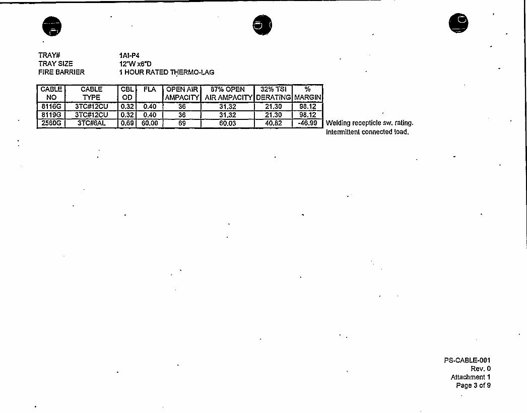
A review ofAttachment 1 indicates that 2560G/1AI-P4 does not have a margin betweenits connected load and the available ampacity aAer being derated in accordance withsections 3.1 and 3.2.
Tray 1AI-P4 contains just three cables, two ofwhich have minor motor operated valveloads (<0.5A). Given the short operating time of these valves (< 2 minutes), the cablespowering them in effect contribute no heat to the steady state inner-tray environment.Therefore these two cables may be disregarded with respect to the derating of the thirdcable, 2560G (i.e.- 2560G need not be derated for placement in tray with other cables).This third cable supplies power to a welding receptacle rated for 60A. To justify theloading of this cable the nature of load must be considered. The nature of the load isinfrequent and intermittent, therefore the emergency overload rating of the cable shouldbe considered. For XLPE type insulation, the emergency overload rating is 130'C.
PS-CABLE-001'Rev. 0
Page 4 of'6

This temperature rating of the cable is for those situations in which the load current is
higher than normal but is not expected to last more than 100 hours at any given time ormore than a total of500 hours in the life of the cable (Reference 5). Adjusting for a
change in heat rise of the cable (90'C to 130'C) in accordance with IPCEA-P-46-426 eq.
5, a free air emergency overload ampacity of 87A is calculated. Applying the 32% TUfactor derates it to 59A.
The portable welding equipment commonly used at DC Cook draws less than 50A. Also,it is expected that during the life of the welding receptacle it would be used within thetime parameters associated with the emergency overload rating of the cable. Thereforethis cable and its loading is considered acceptable.
5.0
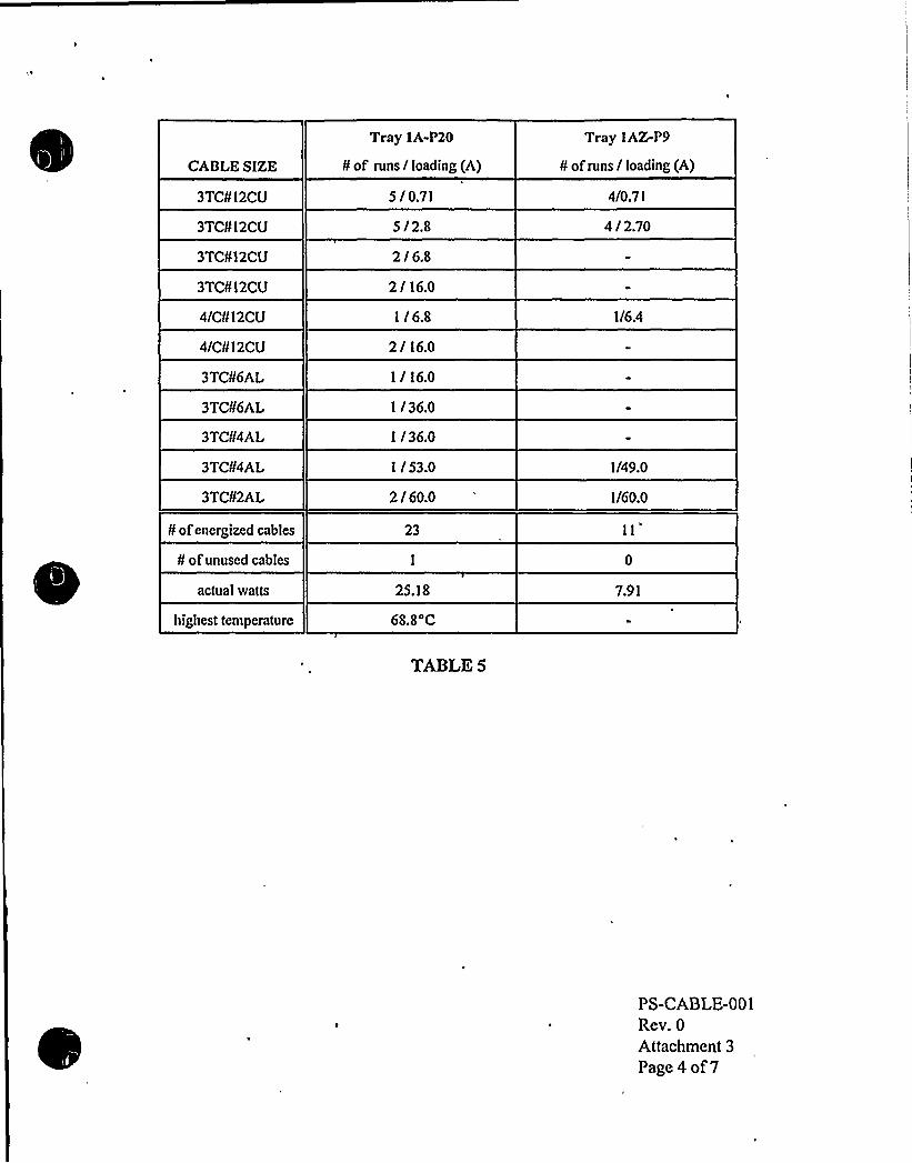
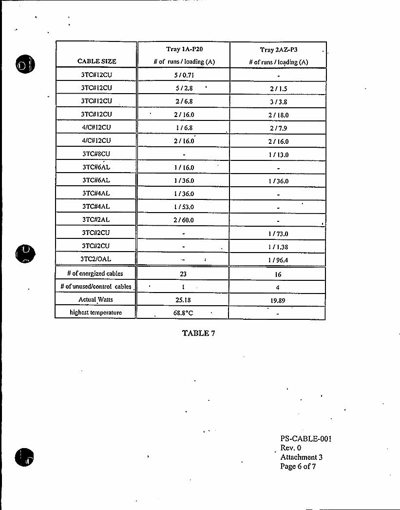
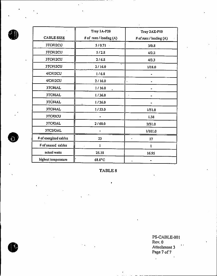
As an alternate means of review of the loading ofThermo-lag wrapped trays listed inAttachment 1, direct comparisons and correlations between tests and actualconfigurations have been made in Attachment 3. This is highly relevant to the study ofampacity loading ofThermo-lag wrapped trays.
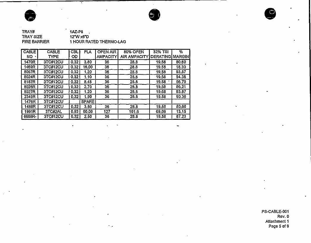
In 1983, the Canton Test Lab performed Test CL-542 (Attachment 4) to simulate theeffects of 1/2" Thermo-lag on conductor temperatures ofspaced cables. These testsreplicated actual installed raceway configurations, including the number and size ofcables, loading and spacing. As an example, CL-542 Tests 1 and 3 were designed toreplicate trays 1AZ-P8 and 1A-P20, respectively. Direct comparison or correlation ofdata provided by these tests and trays under review, provides an excellent means ofassurance that the temperature ratings of the spaced cables willnot be exceeded at thestated loadings while the parent tray is wrapped in 1/2" Thermo-lag.
Attachment 3, Tables 1 and 2, provide a direct comparison between data from CL-542test 1 and 3 and the cables contained in trays 1AZ-P8 and 1A-P20. The test currents usedin the test were equal to or greater than the actual loading of the respective cables. Areview of these tables shows that no cables exceed their temperture rating (90 C).whileenergized at their design loads, in fact, all conductor temperatures are less than 70'C.
Attachment 3, Tables 3 through 8, provide correlations between data from CL-542 test 3
and other trays which are considered to be enveloped by this test. A review of thesetables shows that tray 1A-P20 envelopes all other trays in both number ofcables andloading.
PS-CABLE-001Rev. 0
Page 5 of6
l. IPCEA P-46-4262. ICEA P-54-4403. Texas Utilities Test Report4. DC Cook Electrical Design Standard 1-2-EDS-6425. EPRI Power Plant Reference Guide - Wire and Cable6. DC Cook Tray Contents Listing7. DC Cook Conduit and Cable Drawings
H T
1. Derating tables2. MATHCADfiles3. Test results applied to trays4. CL-542 test report5. Design Verification
PS-CABLE-001Rev. 0Page 6 of 6

0
0
TRAY¹TRAYSIZEFIRE BARRIER
1AI-Pl12"W x6"D1 HOUR RATED THERMO-LAG
CABLENO
CABLETYPE
CBLOD
OPEN AIRAMPACITY
80% OPEN 32% TSIAIR AMPACITY DERATING MARGIN
8255R8174R8177R8113R
3TC¹12CU 0.32 0.333TC¹12CU 0.32 4.003TC¹12CU 0.32 4.003TC¹12CU 0.32 0.33
36
3636
28.828.828.828.8
19.5819.58
98.3179.58
19.58 79.5819.58 98.31
8119R 3TC¹12CU 0.32 0.33 36 28.8 19.58 98.318300R8304R8308R8311R8294R8026R8027R1623R1642R2536R9086R9092R9645R
8755RH80083R28765R
3TC¹12CU . 0.32 0.333TC¹12CU 0.32 0.333TC¹12CU 0.32 0.333TC¹12CU 0.32 0.333TC¹12CU 0.32 0.333TC¹12CU 0.32 2.103TC¹12CU 0.32 1.00
3TC¹12CU 0.32 1.603TC¹12CU 0.32 1.603TC¹12CU 0.32 2.903TC¹6AL 0.69 37.00
3TC¹12CU 0.32 3.48SPARE3 1/C 4/OCU
3TC¹12CU 0.32 2.004/C¹12CU 0.52 10.003TC¹8AL 0.60 25.00
363636363636
3636
3636366936
28.828.828.828.828.828.828.828.828.841.628.828.828.855.228.8
19.58 98.3119.58 98.3119.58 98.3119.58 98.31
28.29 11.6219.58 91.8319.58 91.8319.58 85.1937.54 1.4319.58 82.23
19.58 98.3119.58 89.2819.58 94.8919.58 89.7919.58 48.94
Note: 4/C ¹12CU ampacity Is derived from only 3 conductors utilized
PS-CABLE-001Rev. 0
Attachment 1
Page1 of9


TRAY¹TRAYSIZEFIRE BARRIER
1AI-P212"W x6"D1 HOUR RATED THERMO-LAG
CABLENO
CABLETYPE
CBLOD
OPEN AIRAMPACITY
80% OPEN 32% TSIAIR AMPACITY DERATING MARGIN
8116G 3TC¹12CU 0.32 0.33 36 28.8 19.58 98.318119G8185G8194G8197G8250G8300G8304G8308G8311G8270G
3TC¹12CU 0.32 0.333TC¹12CU 0.32 0.333TC¹12CU 0.32 3.203TC¹12CU 0.32 0.333TC¹1 2CU 0.32 0.333TC¹12CU 0.32 0.333TC¹12CU 0.32 0.333TC¹12CU 0.32 0.333TC¹12CU 0.32 0.333TC¹12CU 0.32 0.70
36363636363636363636
28.828.828.828.828.828.828.828.828.828.8
19.58 98.3119.58 98.3119.58 83.6619.58 98.31
19.58 98.3119.58 98.3119.58 98.3119.58 96.43
19.58 98.3119.58 98.31
2978G2559G
3TC¹6AL3TC¹6AL
SPARESPARE
8756GH 3TC350MCM AL 1.9 150.80 397 317.6 215.97 30.178751 GH8753GH
3TC¹GAL 0.69 15.503TC¹2AL 0.93 49.40 127
55.2101.6
37.5469.09
58.7128.50
8755GH1500G
3TC¹6AL 0.69 37.003TC 2lQ AL 1.27 50.30 206 164.8 112.06 55.11
55.2 ~ 37.54 1.43
PS-CABLE-001Rev. 0
Attachment 1
Page 2 of 9
TRAYSTRAYSIZEFIRE BARRIER
1AI-P412"W x6"D1 HOUR RATED THERMO-LAG
CABLENO
CABLETYPE
8116G 3TC412CU8119G 3TC412CU2560G 3TCKAL
CBL FLA OPEN AIR 87 lo OPEN 32fo TSIOD AMPACITY AIR AMPACITY DERATING MARGIN0.32 0.40 36 31.32 21.30 98.120.32 0.40 36 31.32 2'I.30 98.120.69 60.00 69 60.03 40.82 -46.99 Weiding recepticle sw. rating.
I t 'tt t tdl d.
PS-CABLE-001Rev. 0
Attachment 1
Page 3 of 9
TRAY¹TRAYSIZEFIRE BARRIER
1A-P2012"W x6"D1 HOUR RATED THERMO-LAG
CABLENO
CABLETYPE
CBLOD
FLA OPEN AIRAMPACITY
80% OPENAIR AMPACITY
32/o TSIDERATING MARGIN
8113R8119R1623R1642R
3TC¹12CU3TC¹12CU3TC¹12CU4/C¹12CU
0.32 0.710.32 0.710.32 2.600.54 6.40
36363636
28.828.828.828.8
19.58 96.3719.58 96.37
86.7219.5819.58 67.32
8026R 3TC¹12CU 0.32 2.70 36 28.8 19.58 86.218027R8294R2349R3249R1509R2353R
3TC¹12CU3TC¹12CU3TC¹12CU3TC¹6AL
3TC¹12CU4/C¹12CU
0.32 1.200.32 0.710.32 1.900.69 12.70
SPARE0.52 16.00
363636
36
28.828.828.855.2
28.8
19.58 93.8719.58 96.3719.58 90.3037.54 66.17
19.58 18.302354R 4/C¹12CU 0.54 16.00 36 28.8 19.58 18.302355R2356R
3TC¹12CU3TC¹4AL
0.32 1.500.8 36.00
3694
28,875.2
19.58 92.3451.14 29.60
8984R 3TC¹12CU 0.32 15.60 36 28.8 19.58 20.348987R1656R9217R
3TC¹12CU3TC¹2AL
3TC¹12CU
0.32 15.60 36
0.32 0.71 360.93 60.00 127
28.8101.628.8
19.58 20.3469.09 13.1519.58 96.37
9221R2348R2962R
3TC¹12CU3TC¹12CU3TC¹12CU
0.32 0.710.32 6.800.32 6.80
363636
28.828.828.8
19.58 96.3719.58 65.2819.58 65.28
2361R1440R
8753RH
3TC¹6AL3TC¹2AL3TC¹4AL
0.69 31.40 69
0.8 49.00 940.93 60.00 127
55.2101.675.2
37.54 16.35
51.14 4.1869.09 13.15
Note: 4/C ¹12CU ampacity is derived from only 3 conductors utilized
PS-CABLE-001Rev. 0
Attachment.1Page 4 of 9

TRAY¹TRAYSIZEFIRE BARRIER
1AZ-P812"W x6"D1 HOUR RATED THERMO-LAG
CABLENO-
1470R1469R
CABLETYPE
3TC¹12CU3TC¹12CU
CBLOD0.32 3.800.32 16.00
3636
FLA OPEN AIRAMPACITY
80% OPENAIR AMPACITY
28.8 80.6019.5819.58 18.30
32% TSIDERATING MARGIN
8067R 3TC¹12CU 0.32 1.20 36 28.8 19.58 93.878024R8187R8026R
3TC¹12CU3TC¹12CU3TC¹12CU
0.32 1.100.32 8.480.32 2.70
3636
28.828.828.8
19.58 94.3819.58 '6.7019.58 86.21
8027R 3TC¹12CU 0.32 1.20 36 28.8 1958 93.872349R1476R1488R
3TC¹12CU3TC¹12CU3TC¹12CU
0.32 1.90SPARE
0.32 3.80
36
36
28.8
28.8
19.58 90.30
19.58 80.601991R 3TC¹2AL 0.93 60.00 127 101.6 69.09 13.156666R- 3TC¹12CU 0.32 2.50 36 28.8 19.58 87.23
PS-CABLE-001Rev. 0
Attachment 1
Page 5of9


TRAY¹TRAYSIZEFIRE BARRIER
1AZ-P912"W x6"D1 HOUR RATED THERMO-LAG
CABLENO
CABLETYPE
CBLOD
FLA OPEN AIRAMPACITY
80% OPENAIR AMPACITY
32% TSIDERATING MARGIN
81,1 3R8119R1623R
3TC¹12CU 0.323TC¹12CU 0.323TC¹12CU 0.32
0.710.712.60
3636
28.828.828.8
19.58 96.3796.3719.58
19.58 86.721642R 4/C¹12CU 0.52 6.40 36 28.8 19.58 67.328026R 3TC¹12CU 0.32 2.70 36 28.8 19.58 86.218027R 3TC¹12CU 0.32 1.20 36 28.8 19.58 93.872349R9217R9221R
3TC¹12CU 0.323TC¹12CU 0.323TC¹12CU 0;32
1.900.170.17
-36-3636
28.828.828.8 99.1319.58
19.58 90.3019.58 99.13
1440R 3TC¹2AL 0.93 60.00 127 101.6 69.09 13.158753RH 3TC¹4AL 0.8 49.00 94 75.2 51.14 4.18
Note: 4/C ¹12CU ampacity is derived from only 3 conductors utilized
PS-CABLE-001Rev. 0
Attachment 1
Page 6 of 9
TRAY¹TRAYSIZEFIRE BARRIER
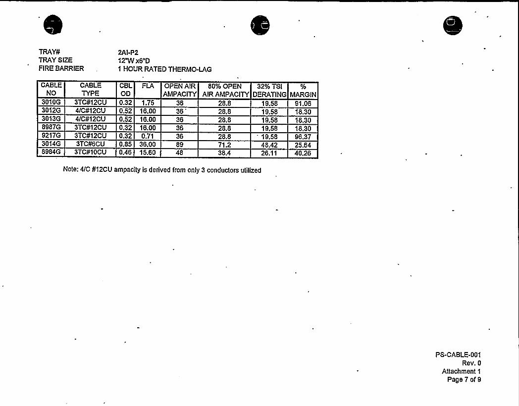
2AI-P212"W x6"D1 HOUR RATED THERMO-LAG
CABLENO
CABLETYPE
CBLOD
OPEN AIR 80% OPEN 32% TSIAMPACITY AIRAMPACITY DERATING MARGIN
3010G 3TC¹12CU 0.323012G 4/C¹12CU 0.523013G 4/C¹12CU 0.528987G 3TC¹12CU 0.329217G 3TC¹12CU 0.323014G 3TC¹6CU 0.858984G 3TC¹1 OCU 0.46
1.7516.0016.0016.000.71
36.0015.60
36363636368948
28.828.828.828.828.871.238.4
19.5819.5819.5819.5819.5848.4226.11
91.0618.3018.3018.3096.3725.6440.26
Note: 4/C ¹12CU ampacity is derived from only 3 conductors utilized
PS-CABLE-001Rev. 0
Attachment 1
Page7of9

TRAY¹.TRAYSIZEFIRE BARRIER
2AZ-P312"W x6"D1 HOUR RATED THERMO-LAG
CABLENO
CABLETYPE
CBLOD
OPEN AIR 80% OPEN 32% TSIAMPACITY AIR AMPACITY DERATING MARGIN
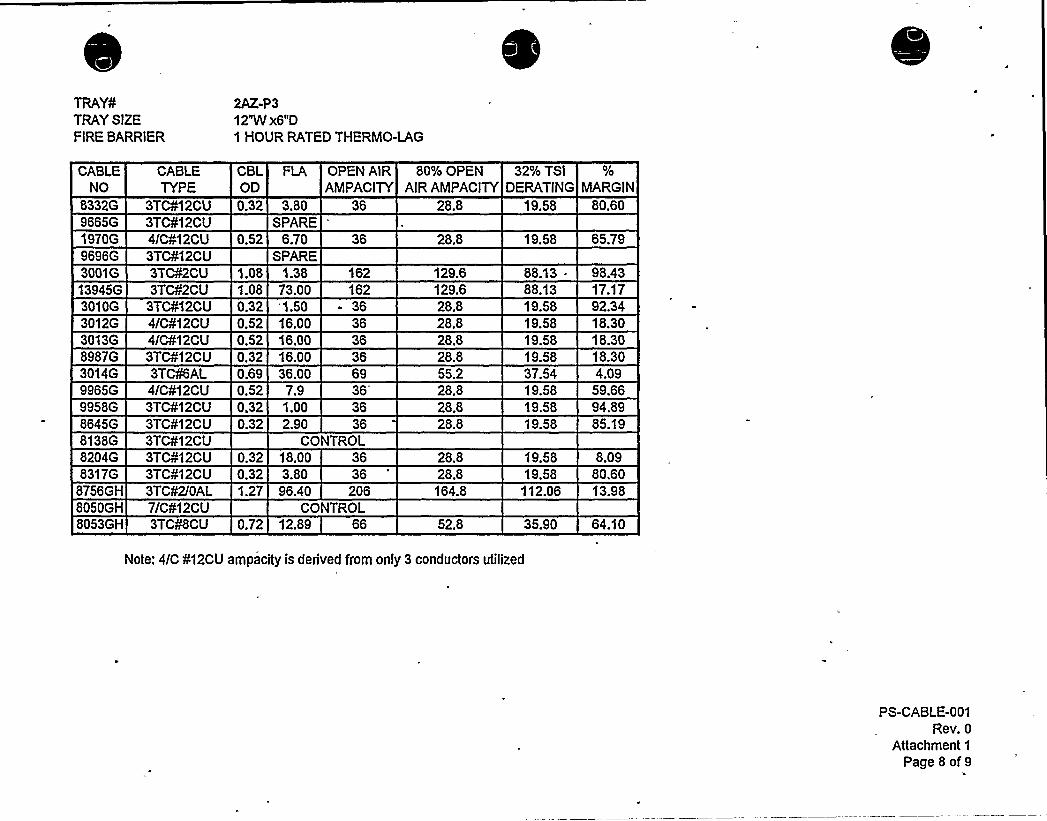
8332G966561970G9696G3001G13945 G3010G3012G3013G8987G3Q14G
9965G9958G8645G8138G
3TC¹12CU3TC¹12CU4/C¹12CU3TC¹12CU3TC¹2CU3TC¹2CU
3TC¹12CU4/C¹12CU4/C¹12CU3TC¹12CU3TC¹6AL4/C¹12CU3TC¹12CU3TC¹12CU3TC¹12CU
0.32 3.80SPARE
0.52 6.70SPARE
1.08 1.381.08 73.000.32 '1.500.52 16.000.52 16.000.32 16.000.69 36.000.52 7.90.32 1.QQ
0.32 2.90CO
36
162363636366936
36NTROL
28.8
28.8
129.6129.628.828.828.828.855.228.828.828.8
19.58
19.58
88.1388.1319.5819.5819.5819.5837.5419.5819.5819.58
80.60
65.79
98.4317.1792.3418.3018.3018.304.09
59.6694.8985.19
82046 3TC¹12CU 0.32 18.00 36 28.8 19.58 8.098317G
8756GH8050GH8053GH
3TC¹12CU3TC¹2/QAL7/C¹12CU3TC¹8CU
0.32 3.801.27 96.40
36206
CONTROL0.72 12.89 66
28.8164.8
52.8
19.58112.06
35.90
80.6Q13.98
64.10
Note: 4/C ¹12CU ampacity is derived from only 3 conductors utilized
PS-CABLE-001Rev. 0
Attachment 1
Page 8 of 9
TRAY¹TRAYSIZEFIRE BARRIER
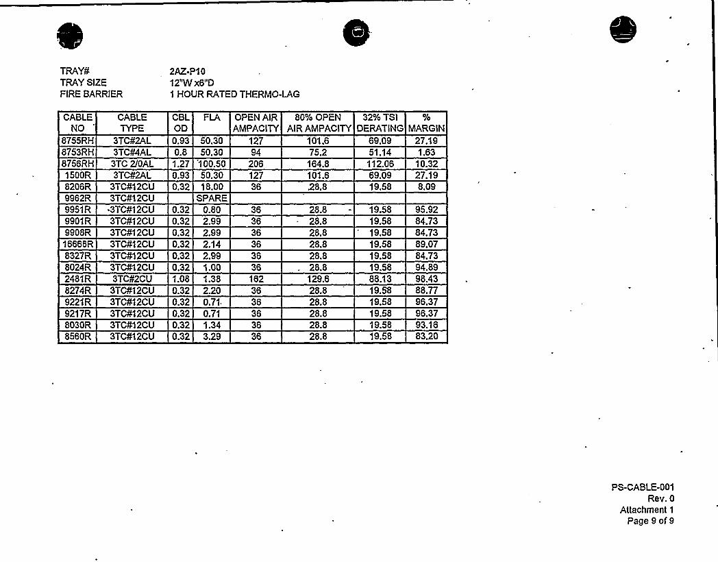
2AZ-P1012"W x6"D1 HOUR RATED THERMO-LAG
CABLENO
CABLETYPE
CBLOD
FLA OPEN AIR 80% OPENAMPACITY AIR AMPACITY
32% TSIDERATING MARGiN
8755RH 3TC¹2AL8753 RH 3TC¹4AL
0.930.8
50.3050.30
12794
101.675.2
69.0951.14
2?.191.63
8756RH 3TC 2/OAL1500R 3TC¹2AL
1.270.93
100.50 20650.30 127
164.8101.6
112.0669.09
10.3227.19
8206R 3TC¹12CU9962R 3TC¹12CU9951R -3TC¹12CU9901R 3TCN2CU9908R 3TC¹12CU
16666R 3TC¹12CU8327R 3TC¹12CU8024R 3TC¹12CU2481R 3TC¹2CU8274R 3TC¹12CU9221R 3TC¹12CU9217R 3TC412CU8030R 3TC¹12CU8560R 3TC¹12CU
0.32
0.320.320.320.320.320.321.080.320.320.320.320.32
18.00SPARE
0.802.992.992.142.991.001.382.200.710.711.343.29
36
363636
36162363636
28.8
28.828.828.828.828.828.8129.628.828.828.828.828.8
19.58
19.5819.5819.5819.5819.5819.5888.1319.5819.5819.5819.5819.58
8.09
95.9284.7384.7389.0784.7394.8998.4388.7796.3796.3793.1683.20
PS-CABLE-001Rev. 0
Attachment 1
Page 9 of 9
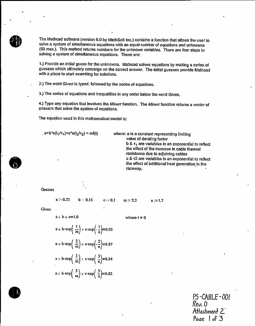
The Mathcad software (version 6.0 by MathSoft Inc.) contains a function that allows the user tosolve a system of simultaneous equations with an equal number of equations and unknowns(50 max.). This method returns numbers for the unknown variables. There are four steps tosolving a system of simultaneous equations. These are:
1.) Provide an initial guess for the unknowns. Mathcad solves equations by making a series ofguesses which ultimately converge on the correct answer. The initial guesses provide Mathcadwith a place to start searching for solutions.
2.) The word Given is typed, followed by the series of equations.
3.) The series of equations and inequalities in any order below the word Given.
4.) Type any equation that involves the Minen function. The Minerr function returns a vector ofanswers that solve the system of equations.
The equation used in this mathematical model is:
. a+b e(tq/~q)+c e(t~/~~) = mf(t) where: a is a constant representing limitingvalue of derating factorb & ~q are variables in an exponential to reflectthe effect of the increase in cable thermalresistance due to adjoining cablesc 8 ~2 are variables in an exponential to reflectthe effect of additional heat generation in theraceway.
Guesses
a ."- 0.75 b: ~ 0.15 c: - 0.1 m:- 2.2 n,'= 1.7
Given
a> bi c=1.0
(1) 1a.t b exp( --) ~ c cxp — =0.93
( m)
"n'here t = 0
/2> 2as b exp~ —
)a c exp -- =0.87
I m) n
/3h 3a i b cxp( -.) i c exp —=0.84
I ) n
a i b expI ..< i c expt —=0.82I )
P5-CABLE-00lRev. 0A8ndleienk
2.'de
I of3
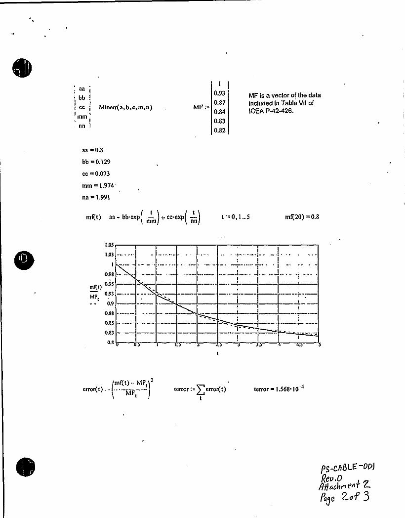
aa
'bb!ji cc t Minerr(a, b, c, m, n)i Imm
r
nn
"'F::. 1
0.93
0.87
0.84
0.83
0.82
MF is a vector of the dataincluded in Table VllofICEA PR2-426.
aa =0.8
bb ~ 0.129
cc =0.073
mm ~ 1.974
nn = 1.991
/ tK tKmf(t) aa - bb exp~ —
jt cc exp —
jt '=0,1..5
Illtn nnjm/20) =0.8
l.05
1.03
0.98
)0.95
0.93MFt
0.9
0.88
0.85
0.83
0.8
/mf(t) ~ MF,error(t),- "----- -—
MFterror: = g error( ti
tterror 1.568 10
I3g t:ABLE'-OPJ
gt.o.O8gujh~f.'"~ ~Pa~e 2 aP 3

0.98
0.96 - ~
0.94
0.92-mgt) 09
0.88
0.86 ~
0,84 ~
0,82—
0.8
0.. 20
0
mft't)
1.002


Comparison ofCI 542 Test I Results fo Tray IAZ-P8
CABLESIZE
'TC¹12CU
3TC¹12CU
3TC¹2AL
TEST
CURRENT'.8
20.0
60.0
RUNS INTRAY'IGHESTCONDUCTORTEMP. ('C)
'5.6
59.7
55.7
CABLE(S)SIMULATED
1470R, 8067R, 8024R,8026R, 8027R, 2349R,16666 R-2
1469R, 8187R, 1488R
1991R
YABLk1
Comparison ofCL-542 Test 3 Resulls fo Tray IA-P20
CABLE
SIZE'TC¹12CU
3TC¹12CU
3TC¹12CU
3TC¹12CU
4/C¹12CU
4/C¹12CU
3TC¹6AL
3TCN6AL
3TC¹4AL
3TCN4AL
3TC¹2AL
TESTCURRENT~
0.71
6.8
16.0
6.8
16.0
16.0
36.0
36.0
53.0
60.0
RUNS IN HIGHEST CONDUCTORTRAY~ TEMP. ('C) i
54.6
57.9
60.4
67.3
55.2
62.7
57.6
65.9
57.9
68.8
63.7
CABLE(S)SIMULATED
8113R,8119R8294 R,9217R,9221R
1623 R,8026R,8027R,2349R,2355R
2348 R,2962R
8984 R,8987R
1642R,
2353R,2354 R
3249R,
2361R
2356R,
8753 RH
1656R,1440R
YABLC< 2
'est data conforms to the actual cables sizes, number of runs, loading and configuration of tray lAZ-P8.2 Test data conforms to the actual cables sizes, number of runs, loading and configuration of tray lA-P20.
PS-CABLE-001Rev. 0Attachment 3
Page 1 of7

CABLESIZE
3TC¹12CU
3TC¹12CU
3TC¹12CU
3TC¹12CU
4/C¹12CU
4/C¹12CU
3TC¹8AL
3TC¹6AL
3TC¹6AL
3TC¹4AL
3TC¹4AL
3TC¹2AL
¹ ofenergized cables
¹ ofunused cables
actual watts
highest temperature
Tray IA-P20
¹ of runs/loading (A)I
5 /0.71
5 /2.8
2/6.8
2/16.0
I /6.8
2/ 16.0
I / 16.0
I /36.0
I /36.0
I /53.0
2/60.0
23
25.18
68.8'C
Tray IAI-PI
¹ ofruns/ loading (A)
8/0.33
5 /2.10
4 /4.0
I /10.0
1 /25.0
I /37.0
20
7.17
TABLE3
PS-CABLE-001Rev. 0Attachment 3
Page2of7


CABLE SIZE
3TC¹12CU
3TC¹12CU
3TC¹12CU
3TC¹12CU
4/C¹12CU
4/C¹12CU
3TC¹6AL
3TC¹6AL
3TC¹4AL
3TC¹4AL
3TC¹2AL
3TC2/OAL
3TC 350MCM AL
¹ ofenergized cables
¹ ofunused 'cables
actual watts
highest temperature
Tray IA-P20
¹of runs/loading{A)
5 /0.71
5 /2.8
2/6.8
2/16.0
I /6.8
2/16.0
I /16.0 ~
I /36.0
I /36.0
I /53.0
2/60.0
23
25.18
68.8'C
Tray IAl-P2
¹ of runs / loading {A)
10/1.0
I/3.2
I/15.5
I/37.0
I/50.0
I/51.0
I/151
16
12.4
TABLE4
PS-CABLE-001Rev. 0Attachment 3
Page3 of7
CABLESIZE
3TC¹12CU
3TC¹12CU
3TC¹12CU
3TC¹12CU
4/C¹12CU
4/C¹12CU
3TC¹6AL
3TC¹6AL
3TC¹4AL
3TC¹4AL
3TC¹2AL
¹ ofenergized cables
¹ ofunused cables
actual watts
highest temperature
Tray IA-P20
¹ of runs/loading (A)
5 /0.71
5/2.8
2/6.8
2/16.0
I /6.8
2/16.0
I / 16.0
I /36.0
I /36.0
I /53.0
2/60.0
23
25.18
68.8'C
Tray IAZ-P9
¹ ofruns/loading (A)
4/0.71
4/2.70
I/6.4
I/49.0
I/60.0
7.91
TABLE5
PS-CABLE-001Rev. 0Attachment 3
Page4of7

Oi

CABLESIZE
3TCII12CU
3TCI112CU
3TC012CU
3TC/I12CU
4/CP12CU
4/CP12CU
3TCI/10CU
3TCN6CU
3TCN6AL
3TC//6AL
3TCP4AL
3TC/I4AL
3TC02AL
// ofenergized cables
//ofunused cables
actual watts
highest temperature
Tray 1A-P20
IIof runs/loading (A)
5 /0.71
5 /2.8
2/6.8
2 / 16.0
1 /6.8
2/16.0
1 / 16.0
1/36.0
1 /36.0
1 /53.0
2/60.0
23
25.18
68.8'C
Tray 2AI-P2
I/ ofruns / loading (A)
2/2.0
1/16.0
2/16.0
1/16.0
1/36.0
7.82
TABLE6
PS-CABLE-001Rev. 0Attachment 3
Page 5 of7
CABLESIZE
3TCN12CU
3TCN12CU
3TCN12CU
3TCN12CU
4/CN12CU
4/CN12CU
3TCN8CU
3TCN6AL
3TCN6AL
3TCN4AL
3TCN4AL
3TCN2AL
3TCN2CU
3TCN2CU
3TC2/OAL
N ofenergized cables
N ofunused/control cables
Actual Watts
highest temperature
Tray IA-P20
N of runs/loading(A)
5/0.71
5 /2.8
2 /6.8
2/ 16.0
I /6.8
2/16.0
I / 16.0
I /36.0
I /36.0
I /53.0
2/60.0
23
25.18
68.8'C
Tray 2AZ-P3
N of runs / loading (A)
2/1.5
3 /3.8
2 / 18.0
2/7.9
2/ 16.0
I /13.0
I /36.0
I /73.0
I / 1.38
I /96.4
16
19.89
TABLE7
PS-CABLE-001Rev. 0Attachment 3
Page6of7

CABLESIZE
3TCN12CU
3TCN12CU
3TCN12CU
3TCN12CU
4/CN12CU
4/CN12CU
3TCN6AL
3TCN6AL
3TCN4AL
3TCN4AL
3TCN2CU
3TCN2AL
3TC2/OAL
Tray IA-P20
N of runs/loading(A)
5/0.71
5 /2.8
2 /6.8
2/ 16.0
I /6.8
2/16.0
I / 16.0
I /36.0
I /36.0
I /53.0
2 /60.0
Tray 2AZ-P10
N of runs / loading (A)
3/0.8
4/2.2
4/3.3
I/18.0
I/51.0
1.38
2/51.0
I/101.0
N ofenergized cables
N ofunused cables
actual watts
highest temperature
23
25.18
68.8'C
17
16.95
TABLE< S
PS-CABLE-001Rev. 0Attachment 3
Page 7 of7