Embed Size (px)
Citation preview

8/6/2019 Engineering Drawing Standards Manual GSFC-X-673!64!1F
http://slidepdf.com/reader/full/engineering-drawing-standards-manual-gsfc-x-673641f 1/128
GSFC X-673-64-1F
ENGINEERING DRAWINGSTANDARDS MANUAL
August 1994
N A T I O
N A L
A E R O N A
U T I C
SAND S P A C E A D
M I N I S T R A T
I O N
U . S. A.

8/6/2019 Engineering Drawing Standards Manual GSFC-X-673!64!1F
http://slidepdf.com/reader/full/engineering-drawing-standards-manual-gsfc-x-673641f 2/128

8/6/2019 Engineering Drawing Standards Manual GSFC-X-673!64!1F
http://slidepdf.com/reader/full/engineering-drawing-standards-manual-gsfc-x-673641f 3/128
X-673-64-1FSupersedes GSFC X-673-64-1E/July 1991
ENGINEERING DRAWINGSTANDARDS MANUAL
Mechanical Engineering BranchGoddard Space Flight CenterGreenbelt, Maryland
August 1994
N A T I O
N A L
A E R O N
A U T I C
SAND S P A C E A D M
I N I S T R A T
I O N
U . S. A.
National Aeronautics and
Space Administration
Goddard Space Flight CenterGreenbelt, Maryland 20771
1994

8/6/2019 Engineering Drawing Standards Manual GSFC-X-673!64!1F
http://slidepdf.com/reader/full/engineering-drawing-standards-manual-gsfc-x-673641f 4/128

8/6/2019 Engineering Drawing Standards Manual GSFC-X-673!64!1F
http://slidepdf.com/reader/full/engineering-drawing-standards-manual-gsfc-x-673641f 5/128
i i i
DESCRIPTION OF REVISION
This revis ion, which supersedes the Goddard Space Fl ight Center (GSFC) StandardX-673-64-1E, Engineering Drawing Standards Manual , i s intended to update and ref lect
the latest formats and s tandards adopted by GSFC.
The fol lowing is a summary of the pr incipal changes and improvements incorporated in
this issue:
a. Addi t ion of Composi te Mater ial Drawing def ini t ion.
b. Changing of the s ignature to a pr inted name in Ti t le blocks.
c . New example of the Metr ic Drawings format and tolerance presentat ion.
d. Improved placement of views on Types of Drawings samples to prevent unnecessary
rework of drawings at a later date.
e . New Engineer ing Order (EO) forms added; old EO forms wil l be phased out .
f . Addi t ional notes on var ious topics added to Note Examples sect ion.
g. Delet ion of microf i lming requirements for drawing format .
h. Flow chart for f l ight projects redef ined.

8/6/2019 Engineering Drawing Standards Manual GSFC-X-673!64!1F
http://slidepdf.com/reader/full/engineering-drawing-standards-manual-gsfc-x-673641f 6/128
iv

8/6/2019 Engineering Drawing Standards Manual GSFC-X-673!64!1F
http://slidepdf.com/reader/full/engineering-drawing-standards-manual-gsfc-x-673641f 7/128
v
PREFACE
The GSFC Engineering Drawing Standards Manual i s the off icial source for therequirements and interpretat ions to be used in the development and presentat ion of
engineer ing drawings and related documentat ion for the GSFC.
The Mechanical Engineer ing Branch, Mechanical Systems Divis ion, has been delegated
the responsibi l i ty for interpretat ion, per iodic updates , and dis t r ibut ion of the GSFC
Engineering Drawing Standards Manual.
Al l Engineer ing Directorate design organizat ions and their contractors shal l adhere to the
requirements of this manual when preparing GSFC engineer ing documentat ion for f l ight
hardware and ground support systems.
Comments or inquir ies concerning this manual should be directed to the Mechanical
Engineer ing Branch, Code 722.
Dr. Al lan Sherman
Director of Engineer ing

8/6/2019 Engineering Drawing Standards Manual GSFC-X-673!64!1F
http://slidepdf.com/reader/full/engineering-drawing-standards-manual-gsfc-x-673641f 8/128
vi
8/6/2019 Engineering Drawing Standards Manual GSFC-X-673!64!1F
http://slidepdf.com/reader/full/engineering-drawing-standards-manual-gsfc-x-673641f 9/128
X-673-64-1F GODDARD SPACE FLIGHT CENTER, Greenbelt , Mary land
ENGINEERING DRAWING STANDARDS MANUAL vii
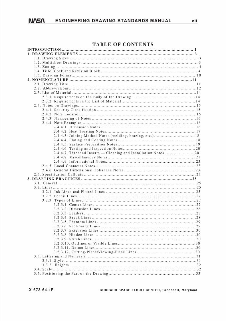
TABLE OF CONTENTSINTRODUCTION .. . . . . . . . . . . . . . . . . . . . . . . . . . . . . . . . . . . . . . . . . . . . . . . . . . . . . . . . . . . . . . . . . . . . . . . . . . . . . . . . . . . . . . . . . . . . . . . . . . . . . . 1
1. DRAWING ELEMENTS .. . . . . . . . . . . . . . . . . . . . . . . . . . . . . . . . . . . . . . . . . . . . . . . . . . . . . . . . . . . . . . . . . . . . . . . . . . . . . . . . . . . . . . . . . 3
1.1 . Drawing Sizes . . . . . . . . . . . . . . . . . . . . . . . . . . . . . . . . . . . . . . . . . . . . . . . . . . . . . . . . . . . . . . . . . . . . . . . . . . . . . . . . . . . . . . . . . . . . . . . . . 3
1 .2 . Mul t i shee t Drawings . . . . . . . . . . . . . . . . . . . . . . . . . . . . . . . . . . . . . . . . . . . . . . . . . . . . . . . . . . . . . . . . . . . . . . . . . . . . . . . . . . . . . . . . 3
1 .3 . Zoning . . . . . . . . . . . . . . . . . . . . . . . . . . . . . . . . . . . . . . . . . . . . . . . . . . . . . . . . . . . . . . . . . . . . . . . . . . . . . . . . . . . . . . . . . . . . . . . . . . . . . . . . . . . . 4
1 .4 . Ti t l e Block and Revis ion Block . . . . . . . . . . . . . . . . . . . . . . . . . . . . . . . . . . . . . . . . . . . . . . . . . . . . . . . . . . . . . . . . . . . . . . . . . 4
1 .5 . Drawing Format . . . . . . . . . . . . . . . . . . . . . . . . . . . . . . . . . . . . . . . . . . . . . . . . . . . . . . . . . . . . . . . . . . . . . . . . . . . . . . . . . . . . . . . . . . . . . .10
2. NOMENCLATURE .. . . . . . . . . . . . . . . . . . . . . . . . . . . . . . . . . . . . . . . . . . . . . . . . . . . . . . . . . . . . . . . . . . . . . . . . . . . . . . . . . . . . . . . . . . . . . . .11
2.1 . Drawing Ti t l e . . . . . . . . . . . . . . . . . . . . . . . . . . . . . . . . . . . . . . . . . . . . . . . . . . . . . . . . . . . . . . . . . . . . . . . . . . . . . . . . . . . . . . . . . . . . . . . . .11
2 .2 . Abbrevia t ions . . . . . . . . . . . . . . . . . . . . . . . . . . . . . . . . . . . . . . . . . . . . . . . . . . . . . . . . . . . . . . . . . . . . . . . . . . . . . . . . . . . . . . . . . . . . . . . . .12
2 .3 . Li s t of Mater ia l . . . . . . . . . . . . . . . . . . . . . . . . . . . . . . . . . . . . . . . . . . . . . . . . . . . . . . . . . . . . . . . . . . . . . . . . . . . . . . . . . . . . . . . . . . . . . .14
2 .3 .1 . Requi rements on the Body of the Drawing . . . . . . . . . . . . . . . . . . . . . . . . . . . . . . . . . . . . . . . . . . . . . . . . 14
2 .3 .2 . Requi rements in the Lis t of Mater ia l . . . . . . . . . . . . . . . . . . . . . . . . . . . . . . . . . . . . . . . . . . . . . . . . . . . . . . . . 14
2 .4 . Notes on Drawings . . . . . . . . . . . . . . . . . . . . . . . . . . . . . . . . . . . . . . . . . . . . . . . . . . . . . . . . . . . . . . . . . . . . . . . . . . . . . . . . . . . . . . . . . .15
2 .4 .1 . Secur i ty Class i f ica t ion . . . . . . . . . . . . . . . . . . . . . . . . . . . . . . . . . . . . . . . . . . . . . . . . . . . . . . . . . . . . . . . . . . . . . . . . . . . 15
2 .4 .2 . Note Loca t ion . . . . . . . . . . . . . . . . . . . . . . . . . . . . . . . . . . . . . . . . . . . . . . . . . . . . . . . . . . . . . . . . . . . . . . . . . . . . . . . . . . . . . . . .15
2 .4 .3 . Number ing of Notes . . . . . . . . . . . . . . . . . . . . . . . . . . . . . . . . . . . . . . . . . . . . . . . . . . . . . . . . . . . . . . . . . . . . . . . . . . . . . . .16
2 .4 .4 . Note Examples . . . . . . . . . . . . . . . . . . . . . . . . . . . . . . . . . . . . . . . . . . . . . . . . . . . . . . . . . . . . . . . . . . . . . . . . . . . . . . . . . . . . . .16
2 .4 .4 .1 . Dimens ion Notes . . . . . . . . . . . . . . . . . . . . . . . . . . . . . . . . . . . . . . . . . . . . . . . . . . . . . . . . . . . . . . . . . . . . . . . . 16
2 .4 .4 .2 . Heat Trea t ing Notes . . . . . . . . . . . . . . . . . . . . . . . . . . . . . . . . . . . . . . . . . . . . . . . . . . . . . . . . . . . . . . . . . . . . 17
2 .4 .4 .3 . Jo in ing Method Notes (weld ing , braz ing, e tc . ) . . . . . . . . . . . . . . . . . . . . . . . . . . . . . . .18
2 .4 .4 .4 . P la t ing and Coating Notes . . . . . . . . . . . . . . . . . . . . . . . . . . . . . . . . . . . . . . . . . . . . . . . . . . . . . . . . . . . 18
2 .4 .4 .5 . Sur face Preparat ion Notes . . . . . . . . . . . . . . . . . . . . . . . . . . . . . . . . . . . . . . . . . . . . . . . . . . . . . . . . . . . 19
2 .4 .4 .6 . Tes t ing and Inspec t ion Notes . . . . . . . . . . . . . . . . . . . . . . . . . . . . . . . . . . . . . . . . . . . . . . . . . . . . . . . 20
2 .4 .4 .7 . Threaded Inser t s — Cleaning and Ins ta l l a t ion Notes . . . . . . . . . . . . . . . . . . . . . . .20
2 .4 .4 .8 . Misce l l aneous Notes . . . . . . . . . . . . . . . . . . . . . . . . . . . . . . . . . . . . . . . . . . . . . . . . . . . . . . . . . . . . . . . . . . .21
2 .4 .4 .9 . Informationa l Notes . . . . . . . . . . . . . . . . . . . . . . . . . . . . . . . . . . . . . . . . . . . . . . . . . . . . . . . . . . . . . . . . . . . . 23
2 .4 .5 . Local Charac te r Notes . . . . . . . . . . . . . . . . . . . . . . . . . . . . . . . . . . . . . . . . . . . . . . . . . . . . . . . . . . . . . . . . . . . . . . . . . . . . 23
2 .4 .6 . Genera l Dimens iona l Tolerance Notes . . . . . . . . . . . . . . . . . . . . . . . . . . . . . . . . . . . . . . . . . . . . . . . . . . . . . . 23
2 .5 . Spec i f i ca t ion Cal lout s . . . . . . . . . . . . . . . . . . . . . . . . . . . . . . . . . . . . . . . . . . . . . . . . . . . . . . . . . . . . . . . . . . . . . . . . . . . . . . . . . . . . . 23
3. DRAFTING PRACTICES .. . . . . . . . . . . . . . . . . . . . . . . . . . . . . . . . . . . . . . . . . . . . . . . . . . . . . . . . . . . . . . . . . . . . . . . . . . . . . . . . . . . . . .25
3.1 . Genera l . . . . . . . . . . . . . . . . . . . . . . . . . . . . . . . . . . . . . . . . . . . . . . . . . . . . . . . . . . . . . . . . . . . . . . . . . . . . . . . . . . . . . . . . . . . . . . . . . . . . . . . . . .25
3 .2 . Lines . . . . . . . . . . . . . . . . . . . . . . . . . . . . . . . . . . . . . . . . . . . . . . . . . . . . . . . . . . . . . . . . . . . . . . . . . . . . . . . . . . . . . . . . . . . . . . . . . . . . . . . . . . . . .25
3 .2 .1 . Ink Lines and Plot t ed Lines . . . . . . . . . . . . . . . . . . . . . . . . . . . . . . . . . . . . . . . . . . . . . . . . . . . . . . . . . . . . . . . . . . . . 25
3 .2 .2 . Penc i l Lines . . . . . . . . . . . . . . . . . . . . . . . . . . . . . . . . . . . . . . . . . . . . . . . . . . . . . . . . . . . . . . . . . . . . . . . . . . . . . . . . . . . . . . . . . .27
3 .2 .3 . Types of Lines . . . . . . . . . . . . . . . . . . . . . . . . . . . . . . . . . . . . . . . . . . . . . . . . . . . . . . . . . . . . . . . . . . . . . . . . . . . . . . . . . . . . . . .27
3 .2 .3 .1 . Center Lines . . . . . . . . . . . . . . . . . . . . . . . . . . . . . . . . . . . . . . . . . . . . . . . . . . . . . . . . . . . . . . . . . . . . . . . . . . . . . . 27
3 .2 .3 .2 . Dimens ion Lines . . . . . . . . . . . . . . . . . . . . . . . . . . . . . . . . . . . . . . . . . . . . . . . . . . . . . . . . . . . . . . . . . . . . . . . . 28
3 .2 .3 .3 . Leaders . . . . . . . . . . . . . . . . . . . . . . . . . . . . . . . . . . . . . . . . . . . . . . . . . . . . . . . . . . . . . . . . . . . . . . . . . . . . . . . . . . . . .28
3 .2 .3 .4 . Break Lines . . . . . . . . . . . . . . . . . . . . . . . . . . . . . . . . . . . . . . . . . . . . . . . . . . . . . . . . . . . . . . . . . . . . . . . . . . . . . . .28
3 .2 .3 .5 . Phantom Lines . . . . . . . . . . . . . . . . . . . . . . . . . . . . . . . . . . . . . . . . . . . . . . . . . . . . . . . . . . . . . . . . . . . . . . . . . . .29
3 .2 .3 .6 . Sec t ioning Lines . . . . . . . . . . . . . . . . . . . . . . . . . . . . . . . . . . . . . . . . . . . . . . . . . . . . . . . . . . . . . . . . . . . . . . . . 293 .2 .3 .7 . Extens ion Lines . . . . . . . . . . . . . . . . . . . . . . . . . . . . . . . . . . . . . . . . . . . . . . . . . . . . . . . . . . . . . . . . . . . . . . . . . 30
3 .2 .3 .8 . Hidden Lines . . . . . . . . . . . . . . . . . . . . . . . . . . . . . . . . . . . . . . . . . . . . . . . . . . . . . . . . . . . . . . . . . . . . . . . . . . . . .30
3 .2 .3 .9 . S t i t ch Lines . . . . . . . . . . . . . . . . . . . . . . . . . . . . . . . . . . . . . . . . . . . . . . . . . . . . . . . . . . . . . . . . . . . . . . . . . . . . . . . 30
3 .2 .3 .10 . Out l ines or Vis ib le Lines . . . . . . . . . . . . . . . . . . . . . . . . . . . . . . . . . . . . . . . . . . . . . . . . . . . . . . . . . . .30
3 .2 .3 .11 . Datum Lines . . . . . . . . . . . . . . . . . . . . . . . . . . . . . . . . . . . . . . . . . . . . . . . . . . . . . . . . . . . . . . . . . . . . . . . . . . . .30
3 .2 .3 .12 . Cut t ing-Plane /Viewing-Plane Lines . . . . . . . . . . . . . . . . . . . . . . . . . . . . . . . . . . . . . . . . . . . . 30
3 .3 . Le t te r ing and Numera ls . . . . . . . . . . . . . . . . . . . . . . . . . . . . . . . . . . . . . . . . . . . . . . . . . . . . . . . . . . . . . . . . . . . . . . . . . . . . . . . . . . . 31
3 .3 .1 . S ty le . . . . . . . . . . . . . . . . . . . . . . . . . . . . . . . . . . . . . . . . . . . . . . . . . . . . . . . . . . . . . . . . . . . . . . . . . . . . . . . . . . . . . . . . . . . . . . . . . . . .31
3 .3 .2 . Height s . . . . . . . . . . . . . . . . . . . . . . . . . . . . . . . . . . . . . . . . . . . . . . . . . . . . . . . . . . . . . . . . . . . . . . . . . . . . . . . . . . . . . . . . . . . . . . . . .32
3 .4 . Sca le . . . . . . . . . . . . . . . . . . . . . . . . . . . . . . . . . . . . . . . . . . . . . . . . . . . . . . . . . . . . . . . . . . . . . . . . . . . . . . . . . . . . . . . . . . . . . . . . . . . . . . . . . . . . .32
3 .5 . Pos i t ioning the Par t on the Drawing . . . . . . . . . . . . . . . . . . . . . . . . . . . . . . . . . . . . . . . . . . . . . . . . . . . . . . . . . . . . . . . . . . 33
8/6/2019 Engineering Drawing Standards Manual GSFC-X-673!64!1F
http://slidepdf.com/reader/full/engineering-drawing-standards-manual-gsfc-x-673641f 10/128
X-673-64-1F GODDARD SPACE FLIGHT CENTER, Greenbelt , Mary land
viii ENGINEERING DRAWING STANDARDS MANUAL
3.5 .1 . P ic tur izat ion . . . . . . . . . . . . . . . . . . . . . . . . . . . . . . . . . . . . . . . . . . . . . . . . . . . . . . . . . . . . . . . . . . . . . . . . . . . . . . . . . . . . . . . . .33
3 .5 .2 . Sec t ions . . . . . . . . . . . . . . . . . . . . . . . . . . . . . . . . . . . . . . . . . . . . . . . . . . . . . . . . . . . . . . . . . . . . . . . . . . . . . . . . . . . . . . . . . . . . . . . .34
3 .5 .3 . Views . . . . . . . . . . . . . . . . . . . . . . . . . . . . . . . . . . . . . . . . . . . . . . . . . . . . . . . . . . . . . . . . . . . . . . . . . . . . . . . . . . . . . . . . . . . . . . . . . . .36
3 .5 .4 . Deta i l s . . . . . . . . . . . . . . . . . . . . . . . . . . . . . . . . . . . . . . . . . . . . . . . . . . . . . . . . . . . . . . . . . . . . . . . . . . . . . . . . . . . . . . . . . . . . . . . . . .373 .5 .5 . Ident i f i ca tion of Sec t ions , Views , and Deta i l s . . . . . . . . . . . . . . . . . . . . . . . . . . . . . . . . . . . . . . . . . . .37
3 .5 .6 . Loca t ing Sec t ions , Views , and Deta i l s . . . . . . . . . . . . . . . . . . . . . . . . . . . . . . . . . . . . . . . . . . . . . . . . . . . . . . 38
4. TYPES OF DRAWINGS .. . . . . . . . . . . . . . . . . . . . . . . . . . . . . . . . . . . . . . . . . . . . . . . . . . . . . . . . . . . . . . . . . . . . . . . . . . . . . . . . . . . . . . . .39
4.1 . Al te red or Se lec ted Vendor Par t Drawing . . . . . . . . . . . . . . . . . . . . . . . . . . . . . . . . . . . . . . . . . . . . . . . . . . . . . . . . . . 39
4 .2 . Assembly Drawing . . . . . . . . . . . . . . . . . . . . . . . . . . . . . . . . . . . . . . . . . . . . . . . . . . . . . . . . . . . . . . . . . . . . . . . . . . . . . . . . . . . . . . . . . .40
4 .3 . Deta i l Drawing . . . . . . . . . . . . . . . . . . . . . . . . . . . . . . . . . . . . . . . . . . . . . . . . . . . . . . . . . . . . . . . . . . . . . . . . . . . . . . . . . . . . . . . . . . . . . . .41
4 .4 . Drawing Tree . . . . . . . . . . . . . . . . . . . . . . . . . . . . . . . . . . . . . . . . . . . . . . . . . . . . . . . . . . . . . . . . . . . . . . . . . . . . . . . . . . . . . . . . . . . . . . . . .42
4 .5 . Elec t ri ca l /Elec t ronic Drawings . . . . . . . . . . . . . . . . . . . . . . . . . . . . . . . . . . . . . . . . . . . . . . . . . . . . . . . . . . . . . . . . . . . . . . . . . 43
4 .5 .1 . Elec t r i ca l and Elec t ronic Symbols. . . . . . . . . . . . . . . . . . . . . . . . . . . . . . . . . . . . . . . . . . . . . . . . . . . . . . . . . . . . 43
4 .5 .2 . Elec t r ica l and Elec t ronic Diagrams . . . . . . . . . . . . . . . . . . . . . . . . . . . . . . . . . . . . . . . . . . . . . . . . . . . . . . . . . . 43
4 .6 . Inseparable Assembly Drawing. . . . . . . . . . . . . . . . . . . . . . . . . . . . . . . . . . . . . . . . . . . . . . . . . . . . . . . . . . . . . . . . . . . . . . . . . 44
4 .7 . Ins ta ll a t ion Assembly Drawing . . . . . . . . . . . . . . . . . . . . . . . . . . . . . . . . . . . . . . . . . . . . . . . . . . . . . . . . . . . . . . . . . . . . . . . . . 45
4 .8 . In te r face Cont ro l Drawing . . . . . . . . . . . . . . . . . . . . . . . . . . . . . . . . . . . . . . . . . . . . . . . . . . . . . . . . . . . . . . . . . . . . . . . . . . . . . . .464 .9 . Matched-Set Drawing . . . . . . . . . . . . . . . . . . . . . . . . . . . . . . . . . . . . . . . . . . . . . . . . . . . . . . . . . . . . . . . . . . . . . . . . . . . . . . . . . . . . . .48
4 .10 . Mechanica l Schemat ic . . . . . . . . . . . . . . . . . . . . . . . . . . . . . . . . . . . . . . . . . . . . . . . . . . . . . . . . . . . . . . . . . . . . . . . . . . . . . . . . . . . . 49
4 .11 . Modi f ica t ion Drawing. . . . . . . . . . . . . . . . . . . . . . . . . . . . . . . . . . . . . . . . . . . . . . . . . . . . . . . . . . . . . . . . . . . . . . . . . . . . . . . . . . . .51
4 .12 . Out l ine Drawing . . . . . . . . . . . . . . . . . . . . . . . . . . . . . . . . . . . . . . . . . . . . . . . . . . . . . . . . . . . . . . . . . . . . . . . . . . . . . . . . . . . . . . . . . . .51
4 .13 . Source Cont ro l Drawing. . . . . . . . . . . . . . . . . . . . . . . . . . . . . . . . . . . . . . . . . . . . . . . . . . . . . . . . . . . . . . . . . . . . . . . . . . . . . . . . . 53
4 .14 . Spec i f i ca tion Cont ro l Drawing. . . . . . . . . . . . . . . . . . . . . . . . . . . . . . . . . . . . . . . . . . . . . . . . . . . . . . . . . . . . . . . . . . . . . . . . 54
4 .15 . S tandard Part Drawing . . . . . . . . . . . . . . . . . . . . . . . . . . . . . . . . . . . . . . . . . . . . . . . . . . . . . . . . . . . . . . . . . . . . . . . . . . . . . . . . . . .56
4 .16 . Tabula ted Drawing . . . . . . . . . . . . . . . . . . . . . . . . . . . . . . . . . . . . . . . . . . . . . . . . . . . . . . . . . . . . . . . . . . . . . . . . . . . . . . . . . . . . . . . .56
4 .17 . Tool ing Drawing . . . . . . . . . . . . . . . . . . . . . . . . . . . . . . . . . . . . . . . . . . . . . . . . . . . . . . . . . . . . . . . . . . . . . . . . . . . . . . . . . . . . . . . . . . .57
4 .18 . Compos i te Mater ia l Drawing . . . . . . . . . . . . . . . . . . . . . . . . . . . . . . . . . . . . . . . . . . . . . . . . . . . . . . . . . . . . . . . . . . . . . . . . . . 58
5. NUMBERING SYSTEM FOR DRAWINGS AND SUPPORTING DOCUMENTATION .60
5.1 . Par t Number ing . . . . . . . . . . . . . . . . . . . . . . . . . . . . . . . . . . . . . . . . . . . . . . . . . . . . . . . . . . . . . . . . . . . . . . . . . . . . . . . . . . . . . . . . . . . . . .61
5 .2 . F ind or I t em Number ing . . . . . . . . . . . . . . . . . . . . . . . . . . . . . . . . . . . . . . . . . . . . . . . . . . . . . . . . . . . . . . . . . . . . . . . . . . . . . . . . . . . 625 .3 . Order of Precedence of Spec i fi ca t ions and Standards . . . . . . . . . . . . . . . . . . . . . . . . . . . . . . . . . . . . . . . . . . 62
5 .3 .1 . Group I . . . . . . . . . . . . . . . . . . . . . . . . . . . . . . . . . . . . . . . . . . . . . . . . . . . . . . . . . . . . . . . . . . . . . . . . . . . . . . . . . . . . . . . . . . . . . . . . .62
5 .3 .2 . Group I I . . . . . . . . . . . . . . . . . . . . . . . . . . . . . . . . . . . . . . . . . . . . . . . . . . . . . . . . . . . . . . . . . . . . . . . . . . . . . . . . . . . . . . . . . . . . . . . 62
5 .3 .3 . Group I I I . . . . . . . . . . . . . . . . . . . . . . . . . . . . . . . . . . . . . . . . . . . . . . . . . . . . . . . . . . . . . . . . . . . . . . . . . . . . . . . . . . . . . . . . . . . . . . 63
5 .3 .4 . Group IV . . . . . . . . . . . . . . . . . . . . . . . . . . . . . . . . . . . . . . . . . . . . . . . . . . . . . . . . . . . . . . . . . . . . . . . . . . . . . . . . . . . . . . . . . . . . . . 63
5 .3 .5 . Group V. . . . . . . . . . . . . . . . . . . . . . . . . . . . . . . . . . . . . . . . . . . . . . . . . . . . . . . . . . . . . . . . . . . . . . . . . . . . . . . . . . . . . . . . . . . . . . . .63
6. ENGINEERING ORDER .. . . . . . . . . . . . . . . . . . . . . . . . . . . . . . . . . . . . . . . . . . . . . . . . . . . . . . . . . . . . . . . . . . . . . . . . . . . . . . . . . . . . . . .64
6.1 . Genera l Requi rements . . . . . . . . . . . . . . . . . . . . . . . . . . . . . . . . . . . . . . . . . . . . . . . . . . . . . . . . . . . . . . . . . . . . . . . . . . . . . . . . . . . . . . 64
6 .2 . Format Sample . . . . . . . . . . . . . . . . . . . . . . . . . . . . . . . . . . . . . . . . . . . . . . . . . . . . . . . . . . . . . . . . . . . . . . . . . . . . . . . . . . . . . . . . . . . . . . . . 64
7. DRAWING REVISIONS .. . . . . . . . . . . . . . . . . . . . . . . . . . . . . . . . . . . . . . . . . . . . . . . . . . . . . . . . . . . . . . . . . . . . . . . . . . . . . . . . . . . . . . . .68
7.1 . Revis ion Methods . . . . . . . . . . . . . . . . . . . . . . . . . . . . . . . . . . . . . . . . . . . . . . . . . . . . . . . . . . . . . . . . . . . . . . . . . . . . . . . . . . . . . . . . . . .68
7 .2 . Revision Ident i f i ca tion . . . . . . . . . . . . . . . . . . . . . . . . . . . . . . . . . . . . . . . . . . . . . . . . . . . . . . . . . . . . . . . . . . . . . . . . . . . . . . . . . . . .68
7 .3 . Revis ion of Mul t i shee t Drawings . . . . . . . . . . . . . . . . . . . . . . . . . . . . . . . . . . . . . . . . . . . . . . . . . . . . . . . . . . . . . . . . . . . . . . 687 .4 . Revis ion Recording . . . . . . . . . . . . . . . . . . . . . . . . . . . . . . . . . . . . . . . . . . . . . . . . . . . . . . . . . . . . . . . . . . . . . . . . . . . . . . . . . . . . . . . . .68
7 .5 . Redrawn or Replaced Drawings . . . . . . . . . . . . . . . . . . . . . . . . . . . . . . . . . . . . . . . . . . . . . . . . . . . . . . . . . . . . . . . . . . . . . . . . 70
8. PARTS LIST AND INDEX LIST .. . . . . . . . . . . . . . . . . . . . . . . . . . . . . . . . . . . . . . . . . . . . . . . . . . . . . . . . . . . . . . . . . . . . . . . . . . . .71
8.1 . Def in i t ions . . . . . . . . . . . . . . . . . . . . . . . . . . . . . . . . . . . . . . . . . . . . . . . . . . . . . . . . . . . . . . . . . . . . . . . . . . . . . . . . . . . . . . . . . . . . . . . . . . . . .71
8 .2 . Requi rements . . . . . . . . . . . . . . . . . . . . . . . . . . . . . . . . . . . . . . . . . . . . . . . . . . . . . . . . . . . . . . . . . . . . . . . . . . . . . . . . . . . . . . . . . . . . . . . . . . 71
8 .2 .1 . Li s t Prepara t ion . . . . . . . . . . . . . . . . . . . . . . . . . . . . . . . . . . . . . . . . . . . . . . . . . . . . . . . . . . . . . . . . . . . . . . . . . . . . . . . . . . . . .71
8 .2 .2 . Li s t Formats . . . . . . . . . . . . . . . . . . . . . . . . . . . . . . . . . . . . . . . . . . . . . . . . . . . . . . . . . . . . . . . . . . . . . . . . . . . . . . . . . . . . . . . . . .72
8 .2 .3 . Revis ion Ident if i ca t ion . . . . . . . . . . . . . . . . . . . . . . . . . . . . . . . . . . . . . . . . . . . . . . . . . . . . . . . . . . . . . . . . . . . . . . . . . . . 72
8 .2 .4 . Dele t ing I t ems . . . . . . . . . . . . . . . . . . . . . . . . . . . . . . . . . . . . . . . . . . . . . . . . . . . . . . . . . . . . . . . . . . . . . . . . . . . . . . . . . . . . . . .72
8 .2 .5 . Adding I t ems . . . . . . . . . . . . . . . . . . . . . . . . . . . . . . . . . . . . . . . . . . . . . . . . . . . . . . . . . . . . . . . . . . . . . . . . . . . . . . . . . . . . . . . . .72
8 .3 . Cover Shee t . . . . . . . . . . . . . . . . . . . . . . . . . . . . . . . . . . . . . . . . . . . . . . . . . . . . . . . . . . . . . . . . . . . . . . . . . . . . . . . . . . . . . . . . . . . . . . . . . . . .72
8 .3 .1 . Format . . . . . . . . . . . . . . . . . . . . . . . . . . . . . . . . . . . . . . . . . . . . . . . . . . . . . . . . . . . . . . . . . . . . . . . . . . . . . . . . . . . . . . . . . . . . . . . . . .72
8/6/2019 Engineering Drawing Standards Manual GSFC-X-673!64!1F
http://slidepdf.com/reader/full/engineering-drawing-standards-manual-gsfc-x-673641f 11/128
X-673-64-1F GODDARD SPACE FLIGHT CENTER, Greenbelt , Mary land
ENGINEERING DRAWING STANDARDS MANUAL ix
8.3 .2 . Ent r i es . . . . . . . . . . . . . . . . . . . . . . . . . . . . . . . . . . . . . . . . . . . . . . . . . . . . . . . . . . . . . . . . . . . . . . . . . . . . . . . . . . . . . . . . . . . . . . . . . .72
8 .4 . Par t s Lis t Cont inuat ion Shee t . . . . . . . . . . . . . . . . . . . . . . . . . . . . . . . . . . . . . . . . . . . . . . . . . . . . . . . . . . . . . . . . . . . . . . . . . . . 75
8 .4 .1 . Format . . . . . . . . . . . . . . . . . . . . . . . . . . . . . . . . . . . . . . . . . . . . . . . . . . . . . . . . . . . . . . . . . . . . . . . . . . . . . . . . . . . . . . . . . . . . . . . . . .75
8 .4 .2 . Ent r i es . . . . . . . . . . . . . . . . . . . . . . . . . . . . . . . . . . . . . . . . . . . . . . . . . . . . . . . . . . . . . . . . . . . . . . . . . . . . . . . . . . . . . . . . . . . . . . . . . .758 .5 . Index Lis t Cont inua t ion Shee t . . . . . . . . . . . . . . . . . . . . . . . . . . . . . . . . . . . . . . . . . . . . . . . . . . . . . . . . . . . . . . . . . . . . . . . . . . 77
8 .5 .1 . Format . . . . . . . . . . . . . . . . . . . . . . . . . . . . . . . . . . . . . . . . . . . . . . . . . . . . . . . . . . . . . . . . . . . . . . . . . . . . . . . . . . . . . . . . . . . . . . . . . .77
8 .5 .2 . Ent r i es . . . . . . . . . . . . . . . . . . . . . . . . . . . . . . . . . . . . . . . . . . . . . . . . . . . . . . . . . . . . . . . . . . . . . . . . . . . . . . . . . . . . . . . . . . . . . . . . . .77
8 .6 . F ind or I t em Number Sys tem of Ident i f i ca tion . . . . . . . . . . . . . . . . . . . . . . . . . . . . . . . . . . . . . . . . . . . . . . . . . . . . 79
8 .6 .1 . Def in i t ion . . . . . . . . . . . . . . . . . . . . . . . . . . . . . . . . . . . . . . . . . . . . . . . . . . . . . . . . . . . . . . . . . . . . . . . . . . . . . . . . . . . . . . . . . . . . .79
8 .6 .2 . Applica t ion and Limi ta t ion . . . . . . . . . . . . . . . . . . . . . . . . . . . . . . . . . . . . . . . . . . . . . . . . . . . . . . . . . . . . . . . . . . . . . 79
8 .6 .3 . Drawing Requi rements . . . . . . . . . . . . . . . . . . . . . . . . . . . . . . . . . . . . . . . . . . . . . . . . . . . . . . . . . . . . . . . . . . . . . . . . . . .80
8 .7 . Li s t of Mater ia l . . . . . . . . . . . . . . . . . . . . . . . . . . . . . . . . . . . . . . . . . . . . . . . . . . . . . . . . . . . . . . . . . . . . . . . . . . . . . . . . . . . . . . . . . . . . . .81
8 .7 .1 . Format . . . . . . . . . . . . . . . . . . . . . . . . . . . . . . . . . . . . . . . . . . . . . . . . . . . . . . . . . . . . . . . . . . . . . . . . . . . . . . . . . . . . . . . . . . . . . . . . . .81
8 .7 .2 . Ent r i es . . . . . . . . . . . . . . . . . . . . . . . . . . . . . . . . . . . . . . . . . . . . . . . . . . . . . . . . . . . . . . . . . . . . . . . . . . . . . . . . . . . . . . . . . . . . . . . . . .81
9. DOCUMENTATION MANAGEMENT .. . . . . . . . . . . . . . . . . . . . . . . . . . . . . . . . . . . . . . . . . . . . . . . . . . . . . . . . . . . . . . . . . . . . 82
9.1 . Typica l Drawing Flow for Fl ight Projec t s . . . . . . . . . . . . . . . . . . . . . . . . . . . . . . . . . . . . . . . . . . . . . . . . . . . . . . . . . . 82
9 .2 . Archiv ing . . . . . . . . . . . . . . . . . . . . . . . . . . . . . . . . . . . . . . . . . . . . . . . . . . . . . . . . . . . . . . . . . . . . . . . . . . . . . . . . . . . . . . . . . . . . . . . . . . . . . . .839 .3 . Computer -Aided Des ign Drawings . . . . . . . . . . . . . . . . . . . . . . . . . . . . . . . . . . . . . . . . . . . . . . . . . . . . . . . . . . . . . . . . . . . . 83
9 .3 .1 . Presenta t ion of Computer -Genera ted Data . . . . . . . . . . . . . . . . . . . . . . . . . . . . . . . . . . . . . . . . . . . . . . . . . 83
9 .3 .2 . Developing and Us ing Computer -Genera ted Drawings . . . . . . . . . . . . . . . . . . . . . . . . . . . . . . . .84
9 .3 .3 . Spec i f i cat ion Data . . . . . . . . . . . . . . . . . . . . . . . . . . . . . . . . . . . . . . . . . . . . . . . . . . . . . . . . . . . . . . . . . . . . . . . . . . . . . . . . . 84
10. DESIGN REFERENCES, STANDARDS, AND SPECIFICATIONS .. . . . . . . . . . . . . . . . . . . . . . . . . .85
10.1 . Dimens ioning and Toleranc ing . . . . . . . . . . . . . . . . . . . . . . . . . . . . . . . . . . . . . . . . . . . . . . . . . . . . . . . . . . . . . . . . . . . . . . . . 85
10.1 .1 . Dimens ioning and Toleranc ing Prac t i ces . . . . . . . . . . . . . . . . . . . . . . . . . . . . . . . . . . . . . . . . . . . . . . . . . 85
10.1 .2 . S ta tements on Dimens ioning . . . . . . . . . . . . . . . . . . . . . . . . . . . . . . . . . . . . . . . . . . . . . . . . . . . . . . . . . . . . . . . . . . 85
10.2 . Met r ic Dimens ioning . . . . . . . . . . . . . . . . . . . . . . . . . . . . . . . . . . . . . . . . . . . . . . . . . . . . . . . . . . . . . . . . . . . . . . . . . . . . . . . . . . . . .86
10.2 .1 . SI Unit s and Symbols . . . . . . . . . . . . . . . . . . . . . . . . . . . . . . . . . . . . . . . . . . . . . . . . . . . . . . . . . . . . . . . . . . . . . . . . . . . 86
10.2 .2 . Uni t Convers ions . . . . . . . . . . . . . . . . . . . . . . . . . . . . . . . . . . . . . . . . . . . . . . . . . . . . . . . . . . . . . . . . . . . . . . . . . . . . . . . . .89
10.2 .2 .1 . Conversion of Dimens ions . . . . . . . . . . . . . . . . . . . . . . . . . . . . . . . . . . . . . . . . . . . . . . . . . . . . . . . . . 89
10.2 .2 .2 . Uni t Rounding . . . . . . . . . . . . . . . . . . . . . . . . . . . . . . . . . . . . . . . . . . . . . . . . . . . . . . . . . . . . . . . . . . . . . . . . . .8910.3 . Des ign References . . . . . . . . . . . . . . . . . . . . . . . . . . . . . . . . . . . . . . . . . . . . . . . . . . . . . . . . . . . . . . . . . . . . . . . . . . . . . . . . . . . . . . . . .92
10.4 . Cont ro l of Sur face Roughness . . . . . . . . . . . . . . . . . . . . . . . . . . . . . . . . . . . . . . . . . . . . . . . . . . . . . . . . . . . . . . . . . . . . . . . . .93
10.4 .1 . Sur face Texture . . . . . . . . . . . . . . . . . . . . . . . . . . . . . . . . . . . . . . . . . . . . . . . . . . . . . . . . . . . . . . . . . . . . . . . . . . . . . . . . . . .93
10.4 .2 . Sur face Texture Symbols . . . . . . . . . . . . . . . . . . . . . . . . . . . . . . . . . . . . . . . . . . . . . . . . . . . . . . . . . . . . . . . . . . . . . . 93
10.4 .3 . Sur face Texture Standards . . . . . . . . . . . . . . . . . . . . . . . . . . . . . . . . . . . . . . . . . . . . . . . . . . . . . . . . . . . . . . . . . . . . . 93
10.5 . Thread Spec i f i ca tions . . . . . . . . . . . . . . . . . . . . . . . . . . . . . . . . . . . . . . . . . . . . . . . . . . . . . . . . . . . . . . . . . . . . . . . . . . . . . . . . . . . .93
10.6 . Welding—Fusion and Res i s tance . . . . . . . . . . . . . . . . . . . . . . . . . . . . . . . . . . . . . . . . . . . . . . . . . . . . . . . . . . . . . . . . . . . . . 95
10.6 .1 . Genera l . . . . . . . . . . . . . . . . . . . . . . . . . . . . . . . . . . . . . . . . . . . . . . . . . . . . . . . . . . . . . . . . . . . . . . . . . . . . . . . . . . . . . . . . . . . . . . .95
10.6 .2 . Bas ic Weld Symbols and Thei r Locat ion Signi f icance . . . . . . . . . . . . . . . . . . . . . . . . . . . . . .95
10.7 . Outgass ing of Spacecraf t Mater ia ls . . . . . . . . . . . . . . . . . . . . . . . . . . . . . . . . . . . . . . . . . . . . . . . . . . . . . . . . . . . . . . . . . 95
10.8 . S tandards and Spec i f i ca tions Index . . . . . . . . . . . . . . . . . . . . . . . . . . . . . . . . . . . . . . . . . . . . . . . . . . . . . . . . . . . . . . . . . 96
10.8 .1 . Nat iona l Bureau of Standards . . . . . . . . . . . . . . . . . . . . . . . . . . . . . . . . . . . . . . . . . . . . . . . . . . . . . . . . . . . . . . . . 96
10.8 .2 . Federa l . . . . . . . . . . . . . . . . . . . . . . . . . . . . . . . . . . . . . . . . . . . . . . . . . . . . . . . . . . . . . . . . . . . . . . . . . . . . . . . . . . . . . . . . . . . . . . .9610.8 .3 . Indus t r ia l . . . . . . . . . . . . . . . . . . . . . . . . . . . . . . . . . . . . . . . . . . . . . . . . . . . . . . . . . . . . . . . . . . . . . . . . . . . . . . . . . . . . . . . . . . . .97
10.8 .4 . Mi l i t a ry . . . . . . . . . . . . . . . . . . . . . . . . . . . . . . . . . . . . . . . . . . . . . . . . . . . . . . . . . . . . . . . . . . . . . . . . . . . . . . . . . . . . . . . . . . . . . .98
10.8 .5 . NASA .. . . . . . . . . . . . . . . . . . . . . . . . . . . . . . . . . . . . . . . . . . . . . . . . . . . . . . . . . . . . . . . . . . . . . . . . . . . . . . . . . . . . . . . . . . . . . . 100
10.9 . S tandards and Spec i fi ca t ions Numer ica l Index . . . . . . . . . . . . . . . . . . . . . . . . . . . . . . . . . . . . . . . . . . . . . . . . 101
APPENDIX A. DESIGN REVIEW DOs AND DON'Ts. . . . . . . . . . . . . . . . . . . . . . . . . . . . . . . . . . . . . . . . . . . . . . . . 107
INDEX.. . . . . . . . . . . . . . . . . . . . . . . . . . . . . . . . . . . . . . . . . . . . . . . . . . . . . . . . . . . . . . . . . . . . . . . . . . . . . . . . . . . . . . . . . . . . . . . . . . . . . . . . . . . . . . . . . . . 110

8/6/2019 Engineering Drawing Standards Manual GSFC-X-673!64!1F
http://slidepdf.com/reader/full/engineering-drawing-standards-manual-gsfc-x-673641f 12/128
X-673-64-1F GODDARD SPACE FLIGHT CENTER, Greenbelt , Mary land
x ENGINEERING DRAWING STANDARDS MANUAL

8/6/2019 Engineering Drawing Standards Manual GSFC-X-673!64!1F
http://slidepdf.com/reader/full/engineering-drawing-standards-manual-gsfc-x-673641f 13/128
X-673-64-1F REV 001 DEC. ‘94 GODDARD SPACE FLIGHT CENTER, Greenbelt , Mary land
ENGINEERING DRAWING STANDARDS MANUAL 1
INTRODUCTION
This drawing s tandards manual establ ishes the convent ions to be adhered to byengineer ing and draf t ing personnel in the preparat ion, revis ion, and complet ion of
engineer ing drawings. This manual sets for th the minimum requirements acceptable at
GSFC for the preparat ion of engineer ing drawings for f l ight hardware and ground
support systems. The requirements specif ied herein are essent ial to the s tandardizat ion
of pract ices and to a uniform interpretat ion of drawings.
A system, payload, or component assembly shal l be completely def ined by means of
drawings, including l is ts , schematics , wir ing diagrams, and specif icat ions, to ensure that
components fabr icated are in accordance with the design. The documentat ion
information shal l serve as a permanent record.
Fl ight hardware shal l be fabr icated in accordance with the approved design documents .
These documents shal l ref lect the character is t ics and acceptance cr i ter ia for al lmater ials , component /par ts , subsystems, and the complete system. The acceptance
cr i ter ia for par ts and mater ials shal l be specif ied by s tandard specif icat ions when
appl icable.
Engineer ing drawings are def ined as those drawings that communicate the requirements
for the manufacture of the end-product i tems, their assembly, and their instal lat ion in the
end product .
The engineer ing drawings prepared by GSFC design personnel or contractors on GSFC
drawing format using GSFC drawing numbers shal l be known as “Government Design
Activi ty Drawings.” Par ts made to these drawings typical ly would be manufactured
through the Fabricat ion Engineer ing Branch, Engineer ing Services Divis ion, GSFC.
“Contractor Design Act ivi ty Drawings”””” (which are a company's drawings bear ing thecompany name, address , federal code ident i f icat ion, and drawing number) should be used
when the company is designing and del iver ing the f inished product in accordance with
the terms of a NASA contract .
The Design Act ivi ty shal l be def ined as an act ivi ty having responsibi l i ty for the design
of an i tem or system. The act ivi ty may be a government ent i ty, a contractor , a vendor , or
another organizat ion such as a universi ty.
Although general ly in accordance with the Department of Defense and industry pract ices
and procedures, this drawing s tandards manual does contain specif ic differences and
except ions to Engineering Drawing Pract ices, MIL-STD-100 E. This manual , whi le not
intended as a manual of inst ruct ion in the basic pr inciples of draf t ing, does set for th the
minimum requirements acceptable at the GSFC. One of those requirements is that
persons engaged in the preparat ion of drawings shal l have a thorough understanding of
the fundamentals of draf t ing and geometr ical dimensioning and tolerancing ( in
accordance with ANSI Y14.5M-198 2, Dimensioning and Tolerancing) in order to
produce interpretable drawings.
8/6/2019 Engineering Drawing Standards Manual GSFC-X-673!64!1F
http://slidepdf.com/reader/full/engineering-drawing-standards-manual-gsfc-x-673641f 14/128
X-673-64-1F REV 001 DEC. ‘94 GODDARD SPACE FLIGHT CENTER, Greenbelt , Mary land
2 ENGINEERING DRAWING STANDARDS MANUAL
8/6/2019 Engineering Drawing Standards Manual GSFC-X-673!64!1F
http://slidepdf.com/reader/full/engineering-drawing-standards-manual-gsfc-x-673641f 15/128
X-673-64-1F REV 001 DEC. ‘94 GODDARD SPACE FLIGHT CENTER, Greenbelt , Mary land
ENGINEERING DRAWING STANDARDS MANUAL 3
1. DRAWING ELEMENTS
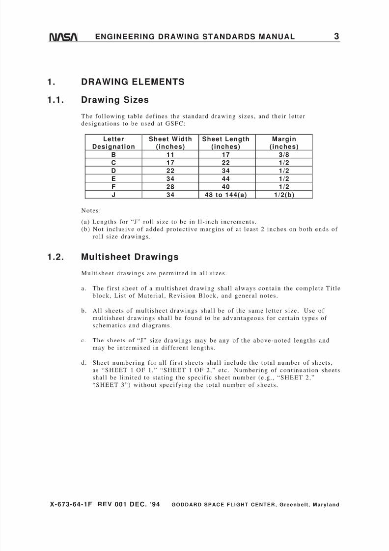
1.1. Drawing Sizes
The fol lowing table def ines the s tandard drawing s izes , and their le t ter
designat ions to be used at GSFC:
Notes:
(a) Lengths for “J” rol l s ize to be in l l - inch increments .
(b) Not inclusive of added protect ive margins of at least 2 inches on both ends of
rol l s ize drawings.
1.2. Multisheet Drawings
Mult isheet drawings are permit ted in al l s izes .
a . The f i rs t sheet of a mult isheet drawing shal l a lways contain the complete Ti t leblock, Lis t of Mater ial , Revision Block, and general notes .
b. Al l sheets of mult isheet drawings shal l be of the same let ter s ize. Use of
mult isheet drawings shal l be found to be advantageous for cer tain types of
schematics and diagrams.
c. The sheets of “J” s ize drawings may be any of the above-noted lengths and
may be intermixed in different lengths.
d. Sheet numbering for al l f i rs t sheets shal l include the total number of sheets ,
as “SHEET 1 OF 1,” “SHEET 1 OF 2,” etc . Numbering of cont inuat ion sheets
shal l be l imited to s tat ing the specif ic sheet number (e .g. , “SHEET 2,”
“SHEET 3”) without specifying the total number of sheets .
LetterDesignation
Sheet Width(inches)
Sheet Length(inches)
Margin(inches)
B 11 17 3/8
C 17 22 1/2
D 22 34 1/2
E 34 44 1/2
F 28 40 1/2
J 34 48 to 144(a) 1/2(b)
8/6/2019 Engineering Drawing Standards Manual GSFC-X-673!64!1F
http://slidepdf.com/reader/full/engineering-drawing-standards-manual-gsfc-x-673641f 16/128
X-673-64-1F REV 001 DEC. ‘94 GODDARD SPACE FLIGHT CENTER, Greenbelt , Mary land
4 ENGINEERING DRAWING STANDARDS MANUAL
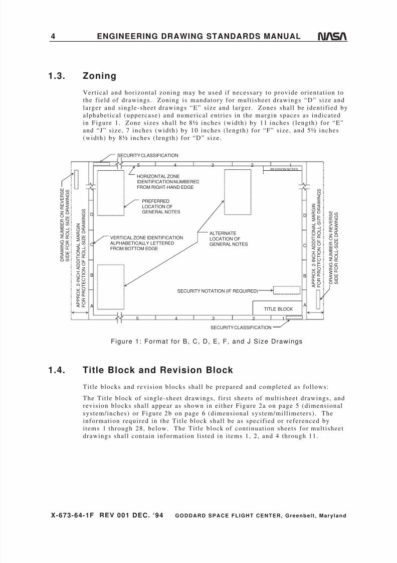
1.3. Zoning
Vert ical and horizontal zoning may be used i f necessary to provide or ientat ion to
the f ield of drawings. Zoning is mandatory for mult isheet drawings “D” size andlarger and s ingle-sheet drawings “E” s ize and larger . Zones shal l be ident i f ied by
alphabet ical (uppercase) and numerical entr ies in the margin spaces as indicated
in Figure 1. Zone s izes shal l be 8½ inches (width) by 11 inches ( length) for “E”
and “J” s ize, 7 inches (width) by 10 inches ( length) for “F” s ize, and 5½ inches
(width) by 8½ inches ( length) for “D” size.
SECURITY NOTATION (IF REQUIRED)
SECURITY CLASSIFICATION
TITLE BLOCK
VERTICAL ZONE IDENTIFICATIONALPHABETICALLY LETTEREDFROM BOTTOM EDGE
ALTERNATE
LOCATION OFGENERAL NOTES
REVISION NOTES
PREFERREDLOCATION OFGENERAL NOTES
HORIZONTAL ZONEIDENTIFICATION NUMBEREDFROM RIGHT-HAND EDGE
SECURITY CLASSIFICATION
D R A W I N G N U M B E R O N R E V E R
S E
S I D E F O R R O L L - S I Z E D R A W I N G S
A P P R O X . 2 - I N C H A D D I T I O N A L M A R G I N
F O R P
R O T E C T I O N O F R O L L - S I Z E D R A W I N G S
A P P R O X . 2 - I N C H A D D I T I O N A L M A R G I N
F O R P R O T E C T I O N O F R O L L - S I Z E D R A W I N
G S
D R A W I N G N U M B E R O N R E V E R S E
S I D E F O R R O L L - S I Z E D R A W I N G S
2345
A
B
C
D
2345
A
B
C
D
1
1
Figure 1: Format for B, C, D, E, F, and J Size Drawings
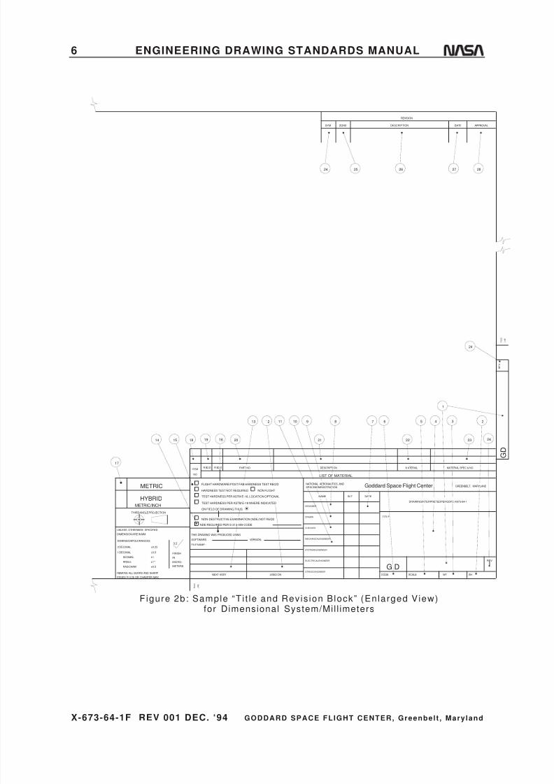
1.4. Title Block and Revision Block
Tit le blocks and revis ion blocks shal l be prepared and completed as fol lows:
The Ti t le block of s ingle-sheet drawings, f i rs t sheets of mult isheet drawings, and
revision blocks shal l appear as shown in ei ther Figure 2a on page 5 (dimensional
system/inches) or Figure 2b on page 6 (dimensional system/mil l imeters) . The
information required in the Ti t le block shal l be as specif ied or referenced by
i tems 1 through 28, below. The Ti t le block of cont inuat ion sheets for mult isheet
drawings shal l contain information l is ted in i tems 1, 2, and 4 through 11.

8/6/2019 Engineering Drawing Standards Manual GSFC-X-673!64!1F
http://slidepdf.com/reader/full/engineering-drawing-standards-manual-gsfc-x-673641f 17/128
X-673-64-1F REV 001 DEC. ‘94 GODDARD SPACE FLIGHT CENTER, Greenbelt , Mary land
ENGINEERING DRAWING STANDARDS MANUAL 5
20
11 10 9
21
8 6
22
5 4
1
3
23
2
24
24 25 26 27 28
71213
14 15 18 19
16
G DWT.CODE
SHSCALE
DRAWING INTERPRETED PER GSFC-X673-64-1
NAME INIT DATE
DESIGNER
CHECKED
APPROVED
APPROVED
APPROVED-STRESS
APPROVED-ENGINEER
UNLESS OTHERWISE SPECIFIED - DIMENSIONS ARE IN INCHES
TOLERANCES:
.XXX.XX
REMOVE ALL BURRS AND SHARP EDGES R .010 OR CHAMFER MAX.
NEXT ASSY USED ON
LIST OF MATERIAL
ITEM
NO
R EQD R EQD PART NO. DESCRIPTION MATERIAL MATERIAL SPEC & NO.
FRACTIONS125
±1/16
F O L D
L I N E
SYM DESCRIPTION DATE APPROVAL
REVISION
G D
FOLDLINE
GREENBELT, MARYLANDNATIONAL AERONAUTICS AND
SPACE ADMINISTRATIONGoddard Space Flight Center
FLIGHT HARDWARE/POST FAB HARDNESS TEST REQ'D
HARDNESS TEST NOT REQUIRED
TEST HARDNESS PER ASTM E-18, LOCATION OPTIONAL
TEST HARDNESS PER ASTM E-18 WHERE INDICATED
ON FIELD OF DRAWING THUS
NO NON-DESTRUCTIVE EXAMINATION (NDE) REQ'D
NDE REQUIRED PER S-313-009 CODE
THIS DRAWING WAS PRODUCED USING
SOFTWARE:
FILE NAME:
VERSION:
TITLE
±.02 ±.005 ±1°
DRAWN
ZONE
NON FLIGHT
REV
R E V
Figure 2a: Sample “T i t le and Revis ion Block” (Enlarged View)for Dimensional System/Inches
8/6/2019 Engineering Drawing Standards Manual GSFC-X-673!64!1F
http://slidepdf.com/reader/full/engineering-drawing-standards-manual-gsfc-x-673641f 18/128
X-673-64-1F REV 001 DEC. ‘94 GODDARD SPACE FLIGHT CENTER, Greenbelt , Mary land
6 ENGINEERING DRAWING STANDARDS MANUAL
SYM
REVISION
APPROVALDATEDESCRIPTIONZONE
F O L D
L I N E
WTCODE SHSCALE
DRAWING INTERPRETED PER GSFC-X673-64-1
NAME INIT DATE
DESIGNER
DRAWN
CHECKED
MECHANICALENGINEER
SYSTEMS ENGINEER
ELECTRICALENGINEER
NEXT ASSY USED ON
LIST OF MATERIAL
ITEM
NO
PART NO DESCRIPTION MATERIAL MATERIAL SPEC & NO
G D
NATIONAL AERONAUTICS ANDGREENBELT, MARYLANDGoddard Space Flight Center
NON-DESTRUCTIVE EXAMINATION (NDE) NOT REQD
NDE REQUIRED PER S-313-009 CODE
THIS DRAWING WAS PRODUCED USING
SOFTWARE:
FILE NAME:
VERSION:
TITLE
F O L D
L I N E
R EQ D R EQ D
STRESS ENGINEER
TEST HARDNESS PER ASTM E-18 WHERE INDICATED
TEST HARDNESS PER ASTM E-18, LOCATION OPTIONAL
ON FIELD OF DRAWING THUS
HARDNESS TEST NOT REQUIRED
FLIGHT HARDWARE/POST FAB HARDNESS TEST REQ'D
G DREV
R E V
NON FLIGHTSPACE ADMINISTRATION
161918
17
1514
13 12 7
2827262524
24
2
23
3
1
45
22
68
21
91011
20 24
EDGES R 0.25 OR CHAMFER MAX
REMOVE ALL BURRS AND SHARP
THIRD ANGLE PROJECTION
UNLESS OTHERWISE SPECIFIED
DIMENSION ARE IN MM
DIMENSION TOLERANCES
RAD/CHAM
METRIC/INCH
ANGLE
2 DECIMAL
1 DECIMAL
DECIMAL
METERS
MICRO-
FINISH
3.2
IN
HYBRID
METRIC
±0.5
±1°
±0.25
±0.5
±1
Figure 2b: Sample “T i t le and Revis ion Block” (Enlarged View)for Dimensional System/Mil l imeters

8/6/2019 Engineering Drawing Standards Manual GSFC-X-673!64!1F
http://slidepdf.com/reader/full/engineering-drawing-standards-manual-gsfc-x-673641f 19/128
X-673-64-1F REV 001 DEC. ‘94 GODDARD SPACE FLIGHT CENTER, Greenbelt , Mary land
ENGINEERING DRAWING STANDARDS MANUAL 7
1 DRAWING NO.: See page 60 .
2 “ S H O F ” : E n te r s h ee t n u mb e r a s a p pl ic ab l e. I n di c at e t o ta l s h ee ts o n lyon shee t 1 .
3 WT: Enter uni t weight calculated at t ime of design i f required.
4 TITLE: See paragraph 2.1 on page 11 for select ion and arrangement of
drawing t i t le . See paragraph 3.3.2 on page 32 for drawing t i t le s ize.
5 SCALE: Enter scale. See paragraph 3.4 on page 32 for select ion of scale.
6 CODE: For drawings prepared by the Goddard Space Fl ight Center (GSFC)
with an off icial GSFC drawing number, enter the three-digi t GSFC code
ident i fying the group responsible for the drawing.
For drawings prepared by a contractor with a contractor drawing number and
format , the contractor 's code number f rom the Commercial and Government
Ent i ty (CAGE) Publ icat ion H4/H8(formerly Federal Supply Code for
Manufacturers (FSCM) H4 and Federal Supply Codes for Non-Manufacturers
(FSCNM) H8) shal l appear .
7 DATE: Enter date of ini t ials .
8 DESIGNER: Enter designer 's pr inted name and ini t ials .
9 DRAWN: Enter draf tsman's pr inted name or i f drawn by the designer , the
designer’s pr inted name may be repeated.
10 CHECKED : Enter design analyst 's pr inted name. This name shal l be an
independent name from al l other names on the drawing. I t represents that the
drawing has been checked against the parameters of this drawing manual and,
where possible, to form, f i t , funct ion, and feasibi l i ty. The checker must have
a thorough understanding of the methods and pract ices of geometr ic
tolerancing and be able to specify such pract ices in accordance with ANSI
Standard Y14.5M-1982, Dimensioning and Tolerancing.
11 APPROVED: Enter the pr inted names of GSFC personnel assigned to approve
the drawing. Project requirements for drawing names shal l vary from program
to program, but each name shal l be ident i f ied. For example, af ter each
approval name, note the fol lowing: “ENG” for engineer , “STRESS” for s t ress
engineer , “QA” for qual i ty assurance engineer , “MATL” for mater ialsengineer , “ELEC” for electr ical engineer , e tc . Al l names in l ine i tems 8
through 11 must be legible. The hand-wri t ten ini t ials on the paper or iginal
are the off icial approval of that document .
12 USED ON: Enter acronym name of program and acronym name of subsystem
or experiment where appl icable.
8/6/2019 Engineering Drawing Standards Manual GSFC-X-673!64!1F
http://slidepdf.com/reader/full/engineering-drawing-standards-manual-gsfc-x-673641f 20/128
X-673-64-1F REV 001 DEC. ‘94 GODDARD SPACE FLIGHT CENTER, Greenbelt , Mary land
8 ENGINEERING DRAWING STANDARDS MANUAL
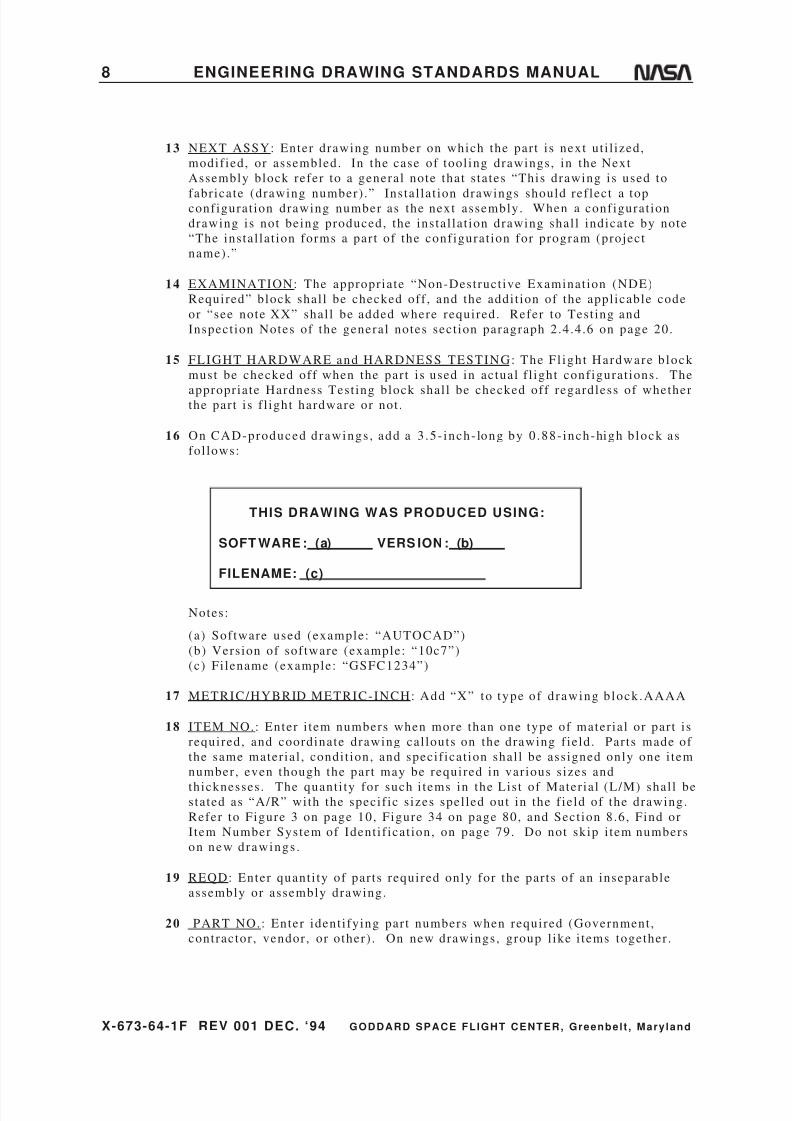
13 NEXT ASSY: Enter drawing number on which the par t is next ut i l ized,
modif ied, or assembled. In the case of tool ing drawings, in the Next
Assembly block refer to a general note that s tates “This drawing is used to
fabricate (drawing number) .” Instal lat ion drawings should ref lect a topconfigurat ion drawing number as the next assembly. When a configurat ion
drawing is not being produced, the instal lat ion drawing shal l indicate by note
“The instal lat ion forms a par t of the configurat ion for program (project
name).”
14 EXAMINATION: The appropriate “Non-Destruct ive Examinat ion (NDE)
Required” block shal l be checked off , and the addi t ion of the appl icable code
or “see note XX” shal l be added where required. Refer to Test ing and
Inspect ion Notes of the general notes sect ion paragraph 2.4.4.6 on page 20.
15 FLIGHT HARDWARE and HARDNESS TESTING: The Fl ight Hardware b lock
must be checked off when the par t is used in actual f l ight configurat ions. The
appropriate Hardness Test ing block shal l be checked off regardless of whetherthe par t is f l ight hardware or not .
16 On CAD-produced drawings , add a 3 .5- inch- long by 0 .88- inch-high b lock as
fol lows:
THIS DRAWING WAS PRODUCED USING:
SOFT WARE : (a) VERS ION : (b)
FILENAME: (c)
Notes:
(a) Software used (example: “AUTOCAD”)
(b) Version of sof tware (example: “10c7”)
(c) Fi lename (example: “GSFC1234”)
17 METRIC/HYBRID METRIC-INCH: Add “X” to type of drawing b lock .AAAA
18 ITEM NO.: Enter i tem numbers when more than one type of mater ial or par t i s
required, and coordinate drawing cal louts on the drawing f ield. Par ts made of
the same mater ial , condi t ion, and specif icat ion shal l be assigned only one i tem
number, even though the par t may be required in var ious s izes and
thicknesses. The quant i ty for such i tems in the List of Mater ial (L/M) shal l bestated as “A/R” with the specif ic s izes spel led out in the f ield of the drawing.
Refer to Figure 3 on page 10, Figure 34 on page 80, and Sect ion 8.6, Find or
I tem Number System of Ident i f icat ion, on page 79. Do not skip i tem numbers
on new drawings .
19 REQD: Enter quant i ty of par ts required only for the par ts of an inseparable
assembly or assembly drawing.
20 PART NO.: Enter ident i fying par t numbers when required (Government ,
contractor , vendor , or other) . On new drawings, group l ike i tems together .
8/6/2019 Engineering Drawing Standards Manual GSFC-X-673!64!1F
http://slidepdf.com/reader/full/engineering-drawing-standards-manual-gsfc-x-673641f 21/128
X-673-64-1F REV 001 DEC. ‘94 GODDARD SPACE FLIGHT CENTER, Greenbelt , Mary land
ENGINEERING DRAWING STANDARDS MANUAL 9
21 DESCRIPTION: Enter mater ial descr ipt ion (plate , e tc .) or a par t name t i t le i f
i t i s another drawing. Enclose reference information such as fastener s izes in
brackets .
22 MATERIAL: Enter the mater ial f rom which the par t is fabr icated. Examples:
“AL ALY”; “CRES”; “BE CU.”
23 MATERIAL SPEC.: Enter the appl icable mater ial specif icat ions, number , and
final condi t ion. Examples: “QQ-A-250/11 6061-T6” for AL ALY plate;
“ASTM A582 303 COND A” for CRES bar .
The information required in the revis ion block shal l be as specif ied or
referenced by i tems 24 through 28, below, and in accordance with “Drawing
Revisions,” paragraph 7, page 68.
24 REVISIONS - SYM: Enter revis ion symbol .
25 REVISIONS - ZONE: Enter zone (where used) .
26 REVISIONS - DESCRIPTION: Enter descr ipt ion of the revis ion (refer to
Sect ion 7, “Drawing Revisions”) .
27 REVISIONS - DATE: Enter date approved by authorized s igner(s) in block.
28 REVISIONS - APPROVAL: Enter s igna ture of GSFC person ass igned to
approve. I f change was by approved EO, drawing only needs approval of the
draf tsman or person incorporat ing the change, and the checker . I f changes
made are not covered by an EO, then approval must include the engineer .
8/6/2019 Engineering Drawing Standards Manual GSFC-X-673!64!1F
http://slidepdf.com/reader/full/engineering-drawing-standards-manual-gsfc-x-673641f 22/128
X-673-64-1F REV 001 DEC. ‘94 GODDARD SPACE FLIGHT CENTER, Greenbelt , Mary land
10 ENGINEERING DRAWING STANDARDS MANUAL
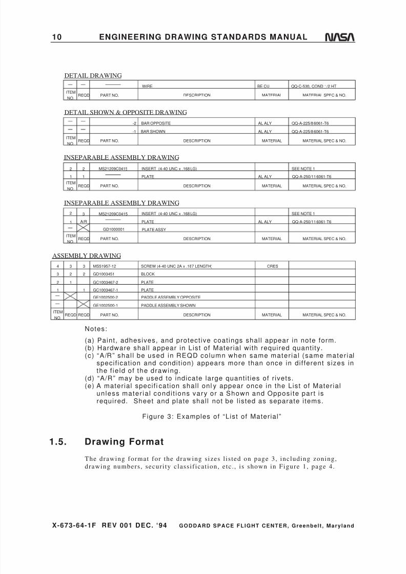
DETAIL DRAWING
INSEPARABLE ASSEMBLY DRAWING
ASSEMBLY DRAWING
INSEPARABLE ASSEMBLY DRAWING
DETAIL SHOWN & OPPOSITE DRAWING
PART NO.REQDITEM
NO.DESCRIPTION MATERIAL MATERIAL SPEC & NO.
WIRE BE CU QQ-C-530, COND 1/2 HT
PART NO.REQDITEM
NO.DESCRIPTION MATERIAL MATERIAL SPEC & NO.
1
2 MS21209C0415
PLATE
INSERT (4-40 UNC x .168 LG)
AL ALY
SEE NOTE 1
QQ-A-250/11 6061-T61
2
PART NO.REQDITEM
NO.DESCRIPTION MATERIAL MATERIAL SPEC & NO.
QQ-A-225/8 6061-T6
QQ-A-225/8 6061-T6
AL ALY
AL ALYBAR OPPOSITE
BAR SHOWN-1
-2
PART NO.REQDITEM
NO.DESCRIPTION MATERIAL MATERIAL SPEC & NO.
1
2
PLATE
INSERT (4-40 UNC x .168 LG)
AL ALY
SEE NOTE 1
QQ-A-250/11 6061-T6
MS21209C0415
GD1000001 PLATE ASSY
A/R
3
PART NO.REQDITEM
NO.DESCRIPTION MATERIAL MATERIAL SPEC & NO.
1
2
3
REQD
3
3
1
2
1
2
MS51957-12
GD1003451
GC1003467-2
GC1003467-1
GE1002500-2
GE1002500-1
4 SCREW (4-40 UNC 2A x .187 LENGTH)
BLOCK
PLATE
PADDLE ASSEMBLY OPPOSITE
PADDLE ASSEMBLY SHOWN
PLATE
CRES
Notes:
(a) Paint , adhesives, and protect ive coat ings shal l appear in note form.(b) Hardware shal l appear in List of Mater ial with required quant i ty.(c) “A/R” shal l be used in REQD column when same mater ia l (same mater ial
specif icat ion and condit ion) appears more than once in dif ferent s izes inthe f ie ld of the drawing.
(d) “A/R” may be used to indicate large quant i t ies of r ivets.(e) A mater ial specif i cat ion shal l onl y appear once in the List of Mater ial
un less mater ia l condi t ions vary or a Shown and Opposi te par t is
required. Sheet and plate shal l not be l isted as separate i tems.
Figure 3: Examples of “List of Mater ial”
1.5. Drawing Format
The drawing format for the drawing s izes l is ted on page 3, including zoning,
drawing numbers , securi ty classi f icat ion, etc . , i s shown in Figure 1, page 4.
8/6/2019 Engineering Drawing Standards Manual GSFC-X-673!64!1F
http://slidepdf.com/reader/full/engineering-drawing-standards-manual-gsfc-x-673641f 23/128
X-673-64-1F REV 001 DEC. ‘94 GODDARD SPACE FLIGHT CENTER, Greenbelt , Mary land
ENGINEERING DRAWING STANDARDS MANUAL 11
2. NOMENCLATURE
2.1. Drawing Title
General information for the select ion or development of a drawing t i t le is as
fol lows:
a. The t i t le should be as br ief as possible but should contain suff icient
information to categorize the par t properly and to dis t inguish i t f rom other
similar par ts .
b. The drawing t i t le shal l consis t of the fol lowing:
1. Ident i fying noun or noun phrase.
2. The most s ignif icant modif ier or modifying phrase.
3. The next most s ignif icant modif ier or modifying phrase.
The noun or noun phrase establ ishes a basic concept of an i tem. The
modif iers serve to narrow the area of concept establ ished by the basic name.
A modif ier is separated from the noun or noun phrase by a comma and from
any preceding modif ier by a comma. The type designator and/or any
addi t ional modif iers required to fur ther ident i fy an i tem are separated from
the f i rs t par t of the t i t le by a dash. Where appl icable, the word “ASSEMBLY”
shal l be used as the last word of the noun phrase.
EXAMPLES:
“Beam, Hoist ing, Guided Missi le”
“Cover , P rotect ive, R ocket Motor—Forward Sect i on”
“Cabinet , Electr ical Equipment—CY-147”
“Transportat ion—Dolly A ssembly, Earth S atel l i te”
c. The noun, or noun phrase, is never abbreviated. Abbreviat ions are used in the
modif iers only when space is l imited. When used, abbreviat ions shal l conform
to Abbrevia t ions , paragraph 2 .2 on page 12 .
d. When one drawing supersedes another , the new drawing, when pract ical , has
the same t i t le .
e . Parentheses are not used to enclose any port ion of the drawing t i t le .
f . Program names (or abbreviat ions) should be added to the “Used On” block and
not the Ti t le block; except ions are on the f inal or top assembly drawing.

8/6/2019 Engineering Drawing Standards Manual GSFC-X-673!64!1F
http://slidepdf.com/reader/full/engineering-drawing-standards-manual-gsfc-x-673641f 24/128
X-673-64-1F REV 001 DEC. ‘94 GODDARD SPACE FLIGHT CENTER, Greenbelt , Mary land
12 ENGINEERING DRAWING STANDARDS MANUAL
2.2. Abbreviations
The purpose of this sect ion is to provide a l is t of authorized abbreviat ions for useon drawings and associated documents . When used, abbreviat ions and acronyms
shal l be in accordance with GSFC STD-256-WE-1 and MIL-STD-12 ( in that order
of precedence) .
a . Uppercase Gothic let ters shal l be used.
b. Abbreviat ions for word combinat ions (e .g. , MMC—Maximum Mater ial
Condi t ion) shal l be used as such and shal l not be separated for use s ingly.
Single abbreviat ions may be combined when necessary.
c . The same abbreviat ion shal l be used for al l tenses, the possessive case and the
singular and plural forms of a given word.
d. Abbreviat ions should be used only to save space or t ime, but never at the
expense of clar i ty.
e . Per iods shal l be used with abbreviat ions that spel l ent i re words to provide
clar i ty and to avoid misinterpretat ion.
The fol lowing abbreviat ions are acceptable to use and are “industry-related”
associat ions not found in GSFC STD-256-WE-1 or MIL-STD-12.
AFBMA Anti-Frict ion Bearing Manufacturers Associat ion, Inc.
1101 Connect icu t Avenue , NW
Suite 700Washington , DC 20036
AGMA American Gear Manufacturers Associat ion, Inc.
1500 King Street
Sui te 201
Ar l ington , VA 22314
ANSI American Nat ional Standard Inst i tute
1430 Broadway
New York , NY 10018
ASME American Society of Mechanical Engineers
345 E. 47th St ree t
New York , NY 10017
ASTM American Society for Test ing and Mater ials
1916 Race Street
Phi ladelphia, PA 19103

8/6/2019 Engineering Drawing Standards Manual GSFC-X-673!64!1F
http://slidepdf.com/reader/full/engineering-drawing-standards-manual-gsfc-x-673641f 25/128
X-673-64-1F REV 001 DEC. ‘94 GODDARD SPACE FLIGHT CENTER, Greenbelt , Mary land
ENGINEERING DRAWING STANDARDS MANUAL 13
AWS American Welding Society, Inc.
550 N.W. Ledeune Road
P.O. Box 351040
Miami, FL 33135
IEEE Inst i tute of Electr ical and Electronic Engineers , Inc.
445 Hose Lane
P.O. Box 1331
Pisca taway, NJ 08855-1331
ISO Internat ional Organizat ion for Standardizat ion/
(Organisat ion Internat ionale de Normalisat ion)
1, rue de Varembé
1211 Geneve 20
Switzer land/Suisse
NEMA National Electr ical Manufacturers Associat ion
2101 L St ree t , NW
Washington , DC 20037
NSA National Standards Associat ion, Inc.
1200 Quince Orchard Blvd
Gaithersburg, MD 20878
NAS Aerospace Industr ies Associat ion of America, Inc.1250 I S t ree t , NW
Washington , DC 20005
SAE Society of Automotive Engineers , Inc.
400 Commonweal th Drive
Warrendale, PA 15096

8/6/2019 Engineering Drawing Standards Manual GSFC-X-673!64!1F
http://slidepdf.com/reader/full/engineering-drawing-standards-manual-gsfc-x-673641f 26/128
X-673-64-1F REV 001 DEC. ‘94 GODDARD SPACE FLIGHT CENTER, Greenbelt , Mary land
14 ENGINEERING DRAWING STANDARDS MANUAL
2.3. List of Material
2.3.1. Requirements on the Body of the Drawing
Each par t l i s ted in the List of Mater ial (Par ts Lis t ) must be
ident i f ied at least once by an I tem (Find) Number on the body of
the drawing (except s ingle i tem drawings and shown and opposi te
i tem drawings) .
Note :
Parts shal l be bracketed, indicat ing reference, when they are
ident i f ied by number and are not noted in the List of Mater ial .
Such par ts are shown in phantom. Repeated i tem numbers shal l be
indicated as reference ei ther within brackets or by the word “REF.”
2.3.2. Requirements in the List of Material
a. The List of Mater ial is a l is t of al l par ts and mater ials cal led
out on the drawing. See Figure 3 on page 10.
b. The quant i ty of par ts noted in the List of Mater ial is the number
required to complete the noted assembly.
c. When a new drawing is made, al l par ts in the List of Mater ial
should be grouped as to type, such as dash number ( for shown
and opposi te assemblies) , GSFC drawings (for detai led par ts) ,
MS parts , NAS parts , e tc . , and l is ted in this sequence.
d. Quant i t ies of Bulk I tems and placement: refer to notes (a)
through (e) on Figure 3 on page 10.
e. Preferred par ts l is ts for par ts , mater ials , and processes can be
found in an unoff icial publ icat ion avai lable for viewing in the
Mechanical Engineer ing Branch. The “Design Select ion Guide”
contains a wide range of hardware, mater ials , design s tandards,
and processes . I t shal l be noted that not al l of the i tems in this
reference guide are rated for space f l ight use.
Note:
All fasteners used in f l ight hardware and cr i t ical nuts and bol tsused on ground support equipment , including al l f l ight /GSE
interfaces, must meet the specif icat ion GSFC Fas tener I n tegr it y
Requirements, GSFC S-313-100, Mater ials Branch, Off ice of
Fl ight Assurance.
8/6/2019 Engineering Drawing Standards Manual GSFC-X-673!64!1F
http://slidepdf.com/reader/full/engineering-drawing-standards-manual-gsfc-x-673641f 27/128
X-673-64-1F REV 001 DEC. ‘94 GODDARD SPACE FLIGHT CENTER, Greenbelt , Mary land
ENGINEERING DRAWING STANDARDS MANUAL 15
2.4. Notes on Drawings
Information other than pictor ial views and dimensions necessary for complet ing adrawing is classi f ied as “notes .” The two types of note forms are General Notes
and Local Character Notes . Notes on a drawing take precedence over
specif icat ion requirements; hence, notes confl ict ing with referenced
specif icat ions shal l not be placed on a drawing unless they are necessary for
deviat ions f rom cer tain provisions of the specif icat ion.
2.4.1. Security Classification
The securi ty classi f icat ion “Top Secret ,” “Secret ,” or
“Confident ial” shal l be located on the drawing as noted in Figure 1
on page 4 .
Each sheet of a mult isheet drawing shal l be individual ly classi f ied
as to i ts contents . The securi ty s tamp on each sheet shal l be that of
the highest classi f icat ion for any i tem shown on that individual
sheet , not the general overal l c lassi f icat ion of the ent i re set of
drawings or the end i tem. On rol l -s ize drawings, the securi ty
classi f icat ion shal l be shown on the reverse s ide at both ends of the
drawings next to the drawing number to enable the classi f icat ion to
be seen without unrol l ing the drawing.
A warning note shal l be included adjacent to the securi ty
classi f icat ion located above the Ti t le block and shal l read as
fol lows:
THIS MATERIAL CONTAINS INFORMATIONAFFECTING THE NATIONAL DEFENSE OF THEUNITED STATES WITHIN THE MEANING OF THEESPIONAGE LAWS, TITLE 18 U.S.C. , SECTIONS 793AND 794. THE TRANSMISSION OR REVELATION OFWHICH IN ANY MANNER TO AN UNAUTHORIZEDPERSON IS PROHIBITED BY LAW.
2.4.2. Note Location
Notes of general character that do not require leaders to indicate
where they apply, and for which provision has not been made in the
supplementary blocks of the drawing format , shal l be located in the
fol lowing order of preference:
a. Adjacent to the upper lef t border and to the lef t of al l views.
b. Immediately to the lef t of the revis ion block.
c. Adjacent to the lower lef t border or below the revis ion block,
space being lef t for extending the revis ion block downward.
This locat ion should be avoided whenever pract ical because the
space required for revis ions cannot be ant icipated.

8/6/2019 Engineering Drawing Standards Manual GSFC-X-673!64!1F
http://slidepdf.com/reader/full/engineering-drawing-standards-manual-gsfc-x-673641f 28/128
X-673-64-1F REV 001 DEC. ‘94 GODDARD SPACE FLIGHT CENTER, Greenbelt , Mary land
16 ENGINEERING DRAWING STANDARDS MANUAL
2.4.3. Numbering of Notes
General notes are numbered consecut ively downward. Note
numbers may be ident i f ied on the f ield of the drawing by placingthe note number in a pennant-shaped f lag at the general note
locat ion and in the f ield of the drawing, or in the List of Mater ial
(Mater ial Specif icat ion column), whichever locat ion is more
appropriate .
2.4.4. Note Examples
The fol lowing notes are l is ted as representat ive examples and
should be used on Engineer ing Drawings when appl icable.
Signif icant information is to be inser ted where blank(s) are
indicated and, for most cases , the notat ions in parentheses are for
information only. (When not appl icable, do not use in note) .
Before using the referenced specif icat ions, check the Department of
Defense Index of Speci f icat ions and Standards Publ icat ions to
ensure that the specif icat ion has not been cancel led or superseded.
Use ei ther of the fol lowing s tatements as main heading for notes:
“Except as noted” or “Unless otherwise specif ied.”
2.4.4.1. Dimension Notes
ALL DIMENSIONS APPLY AFTER SURFACETREATMENT.
DIMENSIONAL LIMITS AND SURFACE ROUGHNESSDESIGNATIONS APPLY (state “BEFORE” or“AFTER”) PLATING.(For other coatings, substitute theappropriate expression for “plating.”)
DIMENSIONS TO APPLY AFTER STRESS RELIEF.
DIMENSIONING AND TOLERANCING TO BEINTERPRETED IN ACCORDANCE WITH ANSIY14.5M-1982.
(Note need be added only when drawingsare not in compliance withGSFC X-673-64-1F.)
GEAR TOLERANCES TO BE IN ACCORDANCE WITHAGMA STANDARD QUALITY (insert number) .
DIMENSIONS ARE IN MILLIMETERS.
8/6/2019 Engineering Drawing Standards Manual GSFC-X-673!64!1F
http://slidepdf.com/reader/full/engineering-drawing-standards-manual-gsfc-x-673641f 29/128
X-673-64-1F REV 001 DEC. ‘94 GODDARD SPACE FLIGHT CENTER, Greenbelt , Mary land
ENGINEERING DRAWING STANDARDS MANUAL 17
TOOLING-CONTROLLED DIMENSION PERTEMPLATE (or “TOOL”) NUMBER GX XXXXXXX. THEACTUAL TOLERANCES ON THE FEATURE'S
LOCATIONS ARE CONTROLLED BY THE TEMPLATE.(Note to be flagged to tooling-affected dimensions and tolerances, which are then enclosed in parenthesesto indicate a reference; templatedrawings shall carry a note statingthe drawing number of the part theyare used to fabricate.)
TORQUE LIMITS FOR THREADED FASTENERSSHALL BE IN ACCORDANCE WITH PROJECTAPPROVED SPECIFICATION NUMBER (ORENGINEERING ANALYSIS) .
2.4.4.2. Heat Treating Notes
Note for beryl l ium copper:
HEAT TREAT IN ACCORDANCE WITH MIL-H-7199 TO(Br ine l l ) .
Note for s teel :
HEAT TREAT IN ACCORDANCE WITH MIL-H-6875 TOXXX.
(XXX = “Rockwell,” “Brinell,” or
Vickers”).
Notes for aluminum:
HEAT TREAT IN ACCORDANCE WITH MIL-H-6088 TO(Br ine l l ) .
HEAT TREAT TO CONDITION AFTER(insert “BRAZING” or “WELDING”) INACCORDANCE WITH MIL-H-6088.
AFTER WELDING, SOLUTION HEAT TREAT AND
ARTIFICIALLY AGE TO T-6 CONDITION PERMIL-H-6088.

8/6/2019 Engineering Drawing Standards Manual GSFC-X-673!64!1F
http://slidepdf.com/reader/full/engineering-drawing-standards-manual-gsfc-x-673641f 30/128
X-673-64-1F REV 001 DEC. ‘94 GODDARD SPACE FLIGHT CENTER, Greenbelt , Mary land
18 ENGINEERING DRAWING STANDARDS MANUAL
2.4.4.3. Joining Method Notes (welding, brazing, etc.)
The fol lowing specif icat ion supersedes MIL-W-8604 for Alum.;
MIL-W-8611A for Stee l , CRES, and HT RES ALY; andMIL-W-18326 for Magnesium:
FUSION WELD IN ACCORDANCE WITHMIL-STD-2219, PROCESS CLASSUSING FILLER METAL AND APPROPRIATEFLUX.(Joint dimension and design should bespecified on the drawing.)
ELECTRON BEAM WELDING IN ACCORDANCE WITHMIL-W-46132.
SOLDER IN ACCORDANCE WITH NHB 5300.4(3A–1) ,USING SOLDER MATERIAL, QQ-S-571, TYPE .
SOLDER IN ACCORDANCE WITH DOD-STD-1866(GENERAL SOLDERING PROCESS FOR ALL TYPESAND MATERIALS FOR NONELECTRICALAPPLICATIONS).
Note for aluminum:
DIP BRAZE IN ACCORDANCE WITH MIL-STD-645;HEAT TREAT TO CONDITION PERMIL-H-6088.
SILVER SOLDER IN ACCORDANCE WITHMIL-B-7883, TYPE GRADE USINGSOLDER MATERIAL QQ-B-654, CLASS .
RIVET IN ACCORDANCE WITH MIL-STD-403.
2.4.4.4. Plating and Coating Notes
Plat ing notes are general ly not for space f l ight hardware use in
rest r icted areas such as opt ics , e lectronics , e tc . , due to f laking.
CADMIUM PLATE IN ACCORDANCE WITH QQ-P-416,TYPE CLASS .
HARD CHROME PLATE (size)—(size) THICK PERQQ-C-320, TYPE , CLASS ; DIMENSIONSSHOWN APPLY AFTER PLATING.
NICKEL PLATE IN ACCORDANCE WITH MIL-STD-171,FINISH (para. number) , TYPE .

8/6/2019 Engineering Drawing Standards Manual GSFC-X-673!64!1F
http://slidepdf.com/reader/full/engineering-drawing-standards-manual-gsfc-x-673641f 31/128
X-673-64-1F REV 001 DEC. ‘94 GODDARD SPACE FLIGHT CENTER, Greenbelt , Mary land
ENGINEERING DRAWING STANDARDS MANUAL 19
SILVER PLATE IN ACCORDANCE WITH QQ-S-365,TYPE , GRADE .
PAINT IN ACCORDANCE WITH MIL-STD-171, TABLE; FINISH NO. COLOR IN
ACCORDANCE WITH FED-STD-595 (color
number).
Notes for aluminum:
ANODIZE IN ACCORDANCE WITH MIL-A-8625, TYPE, CLASS COLOR
(name of color only ) .
IRIDITE IN ACCORDANCE WITH MIL-C-5541,
CLASS .
Note for CRES:
PASSIVATE PER QQ-P-35, TYPE .
FINISH OF MIL-STD-171.Use paragraph that applies to materialbeing used.
Note for i ron and s teel :
APPLY PROTECTIVE PHOSPHATE COATING INACCORDANCE WITH MIL-C-12968, TYPE .(Add “CLASS ”if applicable.)
Note for t i tanium:
SURFACE FINISH TO BE IN ACCORDANCE WITHAMS 2488, TYPE .
2.4.4.5. Surface Preparation Notes
SURFACE TO BE CLEANED AND POLISHED FORVACUUM USE. DO NOT USE ROUGE COMPOUNDSOR CHEMICALS DURING BUFFING OR POLISHINGON ITEMS REQUIRING TANK-TYPE LEAK TESTS.
EXTERNAL SURFACE TO BE BUFFED TO .
BEFORE ELECTROPOLISHING, MASK ALL
SURFACES MARKED .

8/6/2019 Engineering Drawing Standards Manual GSFC-X-673!64!1F
http://slidepdf.com/reader/full/engineering-drawing-standards-manual-gsfc-x-673641f 32/128
X-673-64-1F REV 001 DEC. ‘94 GODDARD SPACE FLIGHT CENTER, Greenbelt , Mary land
20 ENGINEERING DRAWING STANDARDS MANUAL
VAPOR DEGREASING PER ASTM D4126, GENERALSOLVENT GRADE 1,1,1 TRICHLOROETHANE.
2.4.4.6. Testing and Inspection Notes
THIS PART SHALL HAVE A LEAK RATE OF NOT
MORE THAN (1 x 10 -7 CC/SEC OF HELIUM) WHENMEASURED BY A CALIBRATED MASSSPECTROMETER HAVING A SENSITIVITY OF
(1 x 10 -9 CC/SEC WITH GREATER THAN 90%HELIUM) AT A DIFFERENTIAL OF (ONE)ATMOSPHERE OR EQUIVALENT TEST.
RADIOGRAPHIC INSPECTION OF ALL WELDS INACCORDANCE WITH MIL-STD-00453.
ULTRASONIC INSPECTION PER MIL-STD-2154,TYPE (Insert “I” or “II”) , CLASS .(I = Immersion Method, II = ContactMethod.)
For General Fracture Control Plan for Payloads Using the Space
Transportat ion System (STS), refer to GSFC 731-0005-83. One of
the fol lowing notes should be used for par ts requir ing etching
and/or l iquid penetrant inspect ion:
FRACTURE CRITICAL PART - ETCH ANDPENETRANT INSPECT PER GSFC S-313-009,
CODE XXXXX.(Usually used for machined parts.)
FRACTURE CRITICAL PART - DO NOT ETCH PART.PENETRANT INSPECT PER GSFC S-313-009,CODE XXXXX.(Usually used for rolled parts.)
I f areas of a par t are to be etched and inspected pr ior to f inish
machining, a separate drawing note should cal l out this requirement
to avoid cost ly mistakes.
2.4.4.7. Threaded Inserts — Cleaning and InstallationNotes
Note for aluminum and magnet ic surfaces:
CLEAN THREADED INSERTS WITHTRICHLOROETHANE AND BAKE OUT AT 100DEGREES CELSIUS FOR 3 TO 4 HOURS PRIOR TOINSTALLATION. APPLY DRY FILM LUBRICANTGOVT. DESIGNATION M-6003, TYPE (insert
“I” or “II”) PER MIL-L-46010 QPL (LIST).(Type I cure temp. = 150 degrees C.)(Type II cure temp. = 240 degrees C.)
8/6/2019 Engineering Drawing Standards Manual GSFC-X-673!64!1F
http://slidepdf.com/reader/full/engineering-drawing-standards-manual-gsfc-x-673641f 33/128
X-673-64-1F REV 001 DEC. ‘94 GODDARD SPACE FLIGHT CENTER, Greenbelt , Mary land
ENGINEERING DRAWING STANDARDS MANUAL 21
INSTALL THREADED INSERTS PER XXX.(XXX = “MS33537” for coil type,
“MS51835” for Keen type, or“MIL-I-45932/1” for thin wall type.)
INSTALL CLINCH NUTS PER MIL-N-45938/1.
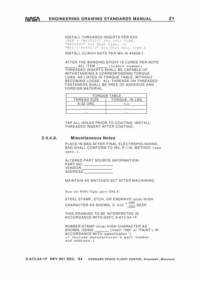
AFTER THE BONDING EPOXY IS CURED PER NOTE, ALL ITEM (insert number)
THREADED INSERTS SHALL BE CAPABLE OFWITHSTANDING A CORRESPONDING TORQUELOAD, AS LISTED IN TORQUE TABLE, WITHOUTBECOMING LOOSE. ALL THREADS ON THREADEDFASTENERS SHALL BE FREE OF ADHESIVE ANDFOREIGN MATERIAL.
TORQUE TABLE
THREAD SIZE TORQUE, IN-LBS6-32 UNC x.x
. . . . . .
. . . . . .
TAP ALL HOLES PRIOR TO COATING; INSTALLTHREADED INSERT AFTER COATING.
2.4.4.8. Miscellaneous Notes
PLACE IN BAG AFTER FINAL ELECTROPOLISHING.
BAG SHALL CONFORM TO MIL-P-116, METHOD (seespec.).
ALTERED PART SOURCE INFORMATION:PART NO. :VENDOR:ADDRESS:
MAINTAIN AS MATCHED SET AFTER MACHINING.
Note for NON-fl ight par ts ONLY:
STEEL STAMP, ETCH, OR ENGRAVE (s ize) HIGH
CHARACTER AS SHOWN, X .010+.005-.000 DEEP.
THIS DRAWING TO BE INTERPRETED INACCORDANCE WITH GSFC X-673-64-1F.
RUBBER STAMP (s ize) HIGH CHARACTER ASSHOWN, USING ( insert “ INK” or “PAINT”) INACCORDANCE WITH (speci f ication * ) .(* Include manufacturer's part numberand address.)

8/6/2019 Engineering Drawing Standards Manual GSFC-X-673!64!1F
http://slidepdf.com/reader/full/engineering-drawing-standards-manual-gsfc-x-673641f 34/128
X-673-64-1F REV 001 DEC. ‘94 GODDARD SPACE FLIGHT CENTER, Greenbelt , Mary land
22 ENGINEERING DRAWING STANDARDS MANUAL
BAG PART PER MIL-P-116, METHOD , ANDTAG WITH PART NUMBER.”
ALTERED SURFACES TO HAVE .
(Refer to paragraph 10.4.1, page 93, forsymbol notation.)
FINISH ALL OVER.
(Refer to paragraph 10.4.1, page 93, forsymbol notation.)
SURFACE ROUGHNESS AS XXX:
MACHINED SURFACES .(where XXX is “ROLLED,” “EXTRUDED,” or“DRAWN”).(Refer to paragraph 10.4.1, page 93, forsymbol notation.)
INSIDE CORNERS R MAXIMUM.
UNIT TO BE STRAIGHTENED AND STRESS-RELIEVED AFTER WELDING.
WELDED OR BRAZED FILLETS TO BE CONFINED TOINSIDE SURFACE.
TWINE SHALL CONFORM TO THE REQUIREMENTSOF MIL-T-713, TYPE , CLASS .
A MANUFACTURER'S CERTIFICATION OF MATERIALSPECIFICATION COMPLIANCE MUST BE SUPPLIEDWITH PART (insert number) .
MAGNETIC SPECIFICATION--PERMEABILITY OFLESS THAN (specify units) .
COMPONENTS MUST BE PACKAGED AND MARKEDIN ACCORDANCE WITH APPLICABLE INTERSTATECOMMERCE COMMISSION ( ICC) REGULATION49-CFR71-78; SHIPMENT SHALL BE MADEDIRECTLY TO THE USING AGENCY. EXPLOSIVE(or other applicable wording) COMPONENTSARE HAZARDOUS AND MUST BE HANDLED INACCORDANCE WITH APPLICABLE SAFETYREGULATION 49-CFR71-78.
8/6/2019 Engineering Drawing Standards Manual GSFC-X-673!64!1F
http://slidepdf.com/reader/full/engineering-drawing-standards-manual-gsfc-x-673641f 35/128
X-673-64-1F REV 001 DEC. ‘94 GODDARD SPACE FLIGHT CENTER, Greenbelt , Mary land
ENGINEERING DRAWING STANDARDS MANUAL 23
2.4.4.9. Informational Notes
Informational notes , such as the fol lowing government r ights to
manufacture note, shal l appear adjacent to the r ight border andTit le block of the drawing:
THE XXXX COMPANY, CHICAGO, IL . , PARTNUMBER XXXX CORRESPONDS TO THE ITEMDEPICTED ON THIS DRAWING, WHICH ISFURNISHED FOR UNRESTRICTED USE INCONNECTION WITH ANY U.S. GOVERNMENTMANUFACTURE OR PROCUREMENT. SUCH USE ISAUTHORIZED BY THE XXX COMPANY LETTER NO.XXX SIGNED AND DATED
. NO OTHER USE IS AUTHORIZED.
2.4.5. Local Character NotesNotes of local character , such as dr i l l notes , thread notes , e tc . , that
require leaders to indicate the features to which they apply, shal l
be located in the f ield of the drawing in posi t ions adjacent to such
features . Each note shal l s tate the number of features to which i t
appl ies unless a leader is drawn to each feature.
2.4.6. General Dimensional Tolerance Notes
The general tolerances entered in the supplementary port ion of the
Tit le block shal l control al l dimensions appl ied to the drawing,
except those specif ical ly labeled “Max,” “Min,” “Ref ,” “Datum,” or
“Basic,” or dimensions having tolerances appl ied direct ly thereto,or dimensions control led by notes or documents invoked on the
drawing. General tolerances may be changed to the prevalent
tolerances that are required by the drawing type. This is done by
str iking through the tolerance and inser t ing the new tolerance
beneath the old. In the case where metr ic tolerancing is required,
see Sect ion 10.2, subparagraph i , for general tolerances.
2.5. Specification Callouts
Normally, only the basic document number of a specif icat ion should be shown on
the drawing, in which case, the latest issue in effect at the t ime of invi tat ion to
bid shal l be imposed in al l procurement act ions. Changes to the specif icat ion
occurr ing subsequent to the t ime of invi tat ion to bid shal l not be imposed incurrent procurement act ions unless the drawing is revised to show the new issue
by basic document number , revis ions, amendment , and/or date and current pro-
curement act ions amended to specify the new drawing revis ion or Engineer ing
Order (EO).
8/6/2019 Engineering Drawing Standards Manual GSFC-X-673!64!1F
http://slidepdf.com/reader/full/engineering-drawing-standards-manual-gsfc-x-673641f 36/128

8/6/2019 Engineering Drawing Standards Manual GSFC-X-673!64!1F
http://slidepdf.com/reader/full/engineering-drawing-standards-manual-gsfc-x-673641f 37/128
X-673-64-1F REV 001 DEC. ‘94 GODDARD SPACE FLIGHT CENTER, Greenbelt , Mary land
ENGINEERING DRAWING STANDARDS MANUAL 25
3. DRAFTING PRACTICES
3.1. General
These draf t ing pract ices are to be employed in the preparat ion of drawings by
GSFC personnel to achieve commonal i ty throughout and resul t in legible
reproduct ions at the least cost f rom original drawings.
Drawings must be complete and unambiguous in interpretat ion. Complete
drawings contain or make reference to al l data necessary for fabr icat ing and
instal l ing the par t and, when appl icable, the necessary test requirements ,
procurement requirements , and source.
Third-angle or thographic project ion shal l be used for mechanical engineer ing
drawings. (Certain diagrams, schematics , e tc . , are excepted.) Al though othertypes of project ion, such as isometr ic , perspect ive, etc . , are not prohibi ted, their
use must be confined to an auxi l iary view on a drawing of a complex par t when
such a view shal l a id in visual izing the par t .
Drawings need not have three views, ( i .e . , one or two views are permissible for
objects that can be completely def ined) . Complementary notes or dimensions are
acceptable in place of the addi t ional views. The rule shal l be that only those
views shal l be drawn that are necessary to convey the required character is t ics of
the par t . Views, dimensions, etc . , shal l not extend into the margins of the
drawing.
3.2. Lines
Acceptable qual i ty of reproduct ions is dependent on the densi ty and uniformity of
l ine work (and let ter ing) . Types of l ines descr ibed herein are merely l ine conven-
t ions, but in every case, each type of l ine shal l be opaque and of uniform width
and shal l be used on al l drawings other than diagrams, such as schematics , e tc .
3.2.1. Ink Lines and Plotted Lines
Lines, whether hand-drawn or plot ted, shal l be opaque and of
uniform width for each type of l ine. Two widths of l ines , i .e . , thin
and thick, wi th their widths in the proport ions of 1:2, shal l be used.
The actual width of each type of l ine shal l be governed by the s ize
and s tyle of the drawing; the relat ive widths of the l ines shal l
approximate those shown in Figure 4 on page 26.
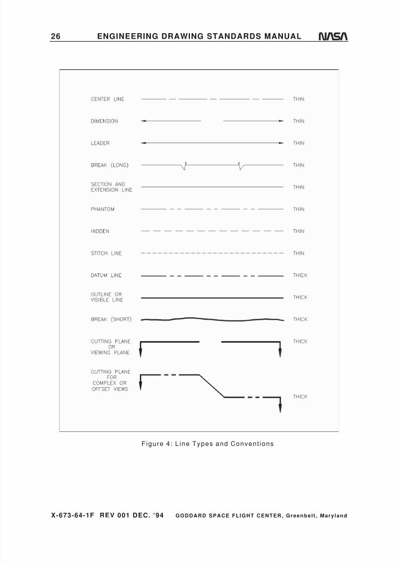
8/6/2019 Engineering Drawing Standards Manual GSFC-X-673!64!1F
http://slidepdf.com/reader/full/engineering-drawing-standards-manual-gsfc-x-673641f 38/128
X-673-64-1F REV 001 DEC. ‘94 GODDARD SPACE FLIGHT CENTER, Greenbelt , Mary land
26 ENGINEERING DRAWING STANDARDS MANUAL
Figure 4: L ine Types and Convent ions
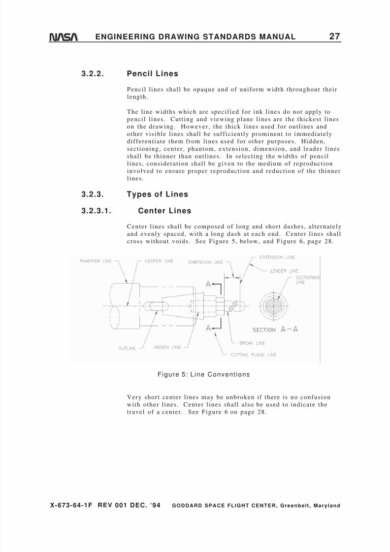
8/6/2019 Engineering Drawing Standards Manual GSFC-X-673!64!1F
http://slidepdf.com/reader/full/engineering-drawing-standards-manual-gsfc-x-673641f 39/128
X-673-64-1F REV 001 DEC. ‘94 GODDARD SPACE FLIGHT CENTER, Greenbelt , Mary land
ENGINEERING DRAWING STANDARDS MANUAL 27
3.2.2. Pencil Lines
Penci l l ines shal l be opaque and of uniform width throughout their
length.
The l ine widths which are specif ied for ink l ines do not apply to
penci l l ines . Cut t ing and viewing plane l ines are the thickest l ines
on the drawing. However , the thick l ines used for out l ines and
other vis ible l ines shal l be suff icient ly prominent to immediately
different iate them from l ines used for other purposes. Hidden,
sect ioning, center , phantom, extension, dimension, and leader l ines
shal l be thinner than out l ines . In select ing the widths of penci l
l ines , considerat ion shal l be given to the medium of reproduct ion
involved to ensure proper reproduct ion and reduct ion of the thinner
l ines .
3.2.3. Types of Lines
3.2.3.1. Center Lines
Center l ines shal l be composed of long and short dashes, al ternately
and evenly spaced, with a long dash at each end. Center l ines shal l
cross without voids. See Figure 5, below, and Figure 6, page 28.
Figure 5: L ine Convent ions
Very short center l ines may be unbroken i f there is no confusion
with other l ines . Center l ines shal l a lso be used to indicate the
travel of a center . See Figure 6 on page 28.

8/6/2019 Engineering Drawing Standards Manual GSFC-X-673!64!1F
http://slidepdf.com/reader/full/engineering-drawing-standards-manual-gsfc-x-673641f 40/128
X-673-64-1F REV 001 DEC. ‘94 GODDARD SPACE FLIGHT CENTER, Greenbelt , Mary land
28 ENGINEERING DRAWING STANDARDS MANUAL
Figure 6: Alternate Posit ion
3.2.3.2. Dimension Lines
Dimension l ines shal l terminate in arrowheads at each end. They
shal l be unbroken except where space is required for the dimension.
The proper method of showing dimensions and tolerances is
explained in Sect ion 1.7 of ANSI Y14.5M-1982.
3.2.3.3. Leaders
Leaders shal l be used to indicate a par t or port ion to which a
number, note, or other reference appl ies and shal l be an unbroken
l ine terminat ing in an arrowhead, dot , or wavy l ine. Arrowheads
should always terminate at a l ine; dots should be within the out l ine
of an object .
3.2.3.4. Break Lines
Short breaks shal l be indicated by sol id f reehand l ines . For long
breaks, ful l ruled l ines with f reehand zigzags shal l be used. Shafts ,
rods, tubes, etc . , which have a port ion of their length broken out ,
shal l have the ends of the break drawn as indicated in Figure 7 on
page 29 .

8/6/2019 Engineering Drawing Standards Manual GSFC-X-673!64!1F
http://slidepdf.com/reader/full/engineering-drawing-standards-manual-gsfc-x-673641f 41/128
X-673-64-1F REV 001 DEC. ‘94 GODDARD SPACE FLIGHT CENTER, Greenbelt , Mary land
ENGINEERING DRAWING STANDARDS MANUAL 29
Figure 7: Break Lines
3.2.3.5. Phantom Lines
Phantom l ines shal l be used to indicate the al ternate posi t ion of
par ts of the i tem del ineated, repeated detai l , or the relat ive posi t ion
of an absent par t and shal l be composed of al ternat ing one long and
two short dashes, evenly spaced, with a long dash at each end. See
Figure 5 on page 27 , F igure 6 on page 28 , and Figure 8 , be low.
Figure 8: Repeated Detai l
3.2.3.6. Sectioning Lines
Sect ioning l ines shal l be used to indicate the exposed surfaces of
an object in a sect ional view. They are general ly thin ful l l ines ,
but may vary with the kind of mater ial shown in sect ion.

8/6/2019 Engineering Drawing Standards Manual GSFC-X-673!64!1F
http://slidepdf.com/reader/full/engineering-drawing-standards-manual-gsfc-x-673641f 42/128
X-673-64-1F REV 001 DEC. ‘94 GODDARD SPACE FLIGHT CENTER, Greenbelt , Mary land
30 ENGINEERING DRAWING STANDARDS MANUAL
3.2.3.7. Extension Lines
Extension l ines are used to indicate the extension of a surface or to
point to a locat ion outside the par t out l ine. They s tar t wi th a short ,vis ible gap from the out l ine of the par t and are usual ly
perpendicular to their associated dimension l ines .
3.2.3.8. Hidden Lines
Hidden l ines shal l consis t of short dashes, evenly spaced. These
l ines are used to show the hidden features of a par t . They shal l
always begin with a dash in contact with the l ine f rom which they
begin, except when such a dash would form a cont inuat ion of a ful l
l ine. Dashes shal l touch at corners , and arcs shal l begin with
dashes on the tangent points . See Figure 5 on page 27 and Figure 8
on page 29 .
3.2.3.9. Stitch Lines
Sti tch l ines shal l be used to indicate the s t i tching or sewing l ines
on an ar t icle and shal l consis t of a ser ies of very short dashes,
approximately half the length of dash or hidden l ines , evenly
spaced. Long l ines of s t i tching may be indicated by a ser ies of
s t i tch l ines connected by phantom l ines.
3.2.3.10. Outlines or Visible Lines
The out l ine or vis ible l ine shal l be used for al l l ines on the drawing
represent ing vis ible l ines on the object ; see Figure 5 on page 27.
3.2.3.11. Datum Lines
Datum l ines shal l be used to indicate the posi t ion of a datum plane
and shal l consis t of one long dash and two short dashes, evenly
spaced.
3.2.3.12. Cutting-Plane/Viewing-Plane Lines
The cut t ing-plane l ines shal l be used to indicate a plane or planes
in which a sect ion is taken. The viewing-plane l ines shal l be used
to indicate the plane or planes f rom which a surface or surfaces are
viewed. On simple views, the cut t ing planes shal l be indicated asshown in Figure 9 on page 31. View shal l be shown in back of the
cut t ing plane (3rd angle) .

8/6/2019 Engineering Drawing Standards Manual GSFC-X-673!64!1F
http://slidepdf.com/reader/full/engineering-drawing-standards-manual-gsfc-x-673641f 43/128
X-673-64-1F REV 001 DEC. ‘94 GODDARD SPACE FLIGHT CENTER, Greenbelt , Mary land
ENGINEERING DRAWING STANDARDS MANUAL 31
Figure 9: Ful l Sect ional View
On complex views, or when the cut t ing planes are bent or offset ,
the cut t ing planes shal l be indicated as shown in Figure 10.
Figure 10: Offset Sect ions

8/6/2019 Engineering Drawing Standards Manual GSFC-X-673!64!1F
http://slidepdf.com/reader/full/engineering-drawing-standards-manual-gsfc-x-673641f 44/128
X-673-64-1F REV 001 DEC. ‘94 GODDARD SPACE FLIGHT CENTER, Greenbelt , Mary land
32 ENGINEERING DRAWING STANDARDS MANUAL
3.3. Lettering and Numerals
All let ter ing shal l be uppercase (capi tal le t ters) . Numbers shal l be Arabic
numerals . The let ter ing and numerals shal l a lwyas be placed in a horizontalreading posi t ion as far as pract icable. Other than this , le t ter ing shal l be in a
horizontal reading posi t ion when the drawing is rotated 90° clockwise. Legible
let ter ing is essent ial for reproduct ions. Let ters and/or numerals shal l not run
together .
When typewri t ten let ters or digi ts are used on drawings or related data, nothing
smaller than pica type is permit ted.
3.3.1. Style
Other than being uppercase Roman and placed in a horizontal
reading posi t ion, the let ter ing is that of the individual 's s tyle .
3.3.2. Heights
Letter ing heights shal l be as fol lows:
Drawing Feature:
Let ter ing
height in
inches
Drawing number in ident i f icat ion blocks .25
Drawing t i t le and descr ipt ion of drawing type above L/M .25
Drawing subt i t le , border , le t ters , and numerals .19
Sect ion, detai l , view, and tabulat ion let ters .25
Descript ion t i t les of sect ion, detai l , view, notes , andtabulat ions .19
Dimensions, tolerances, l imits , notes , subt i t les , tables ,
revis ion, and zone let ters on the f ield of the drawing .16
List of mater ials information, name blocks, used on, and
next assy
.14
Note: Use of f i t text is not al lowed.
3.4. Scale
Drawings shal l be made to ful l scale unless the par ts (or assembly) are too large
to permit i t or so smal l and complex that drawing to an enlarged scale is essent ial
for clar i ty. When the main views of large par ts are drawn to a reduced scale, the
detai l views “taken” to clar i fy detai l should be made to ful l scale whenever
possible. When the par t has been drawn to an enlarged scale for clar i ty, i t i s not
necessary to make an actual-s ize view.
a. The scales preferred for engineer ing drawings are ful l s ize 1/1, reduced 1/2,
1/4, 1/10, 1/20, and enlarged 2/1, 4/1, 10/1, 20/1. The computer data base for
the format s ize shal l be 1/1 at al l t imes.

8/6/2019 Engineering Drawing Standards Manual GSFC-X-673!64!1F
http://slidepdf.com/reader/full/engineering-drawing-standards-manual-gsfc-x-673641f 45/128
X-673-64-1F REV 001 DEC. ‘94 GODDARD SPACE FLIGHT CENTER, Greenbelt , Mary land
ENGINEERING DRAWING STANDARDS MANUAL 33
EXCEPTION:
Certain drawings or f igures , by their very nature, cannot be drawn to a
specif ic scale ( for example, wir ing and schematic diagram drawings.) Thescale designat ion for these cases is “NONE.” See “b,” below.
b. The scale, as noted above, or the word “NONE” must be entered in the Ti t le
block. Do not use the word “SIZE” fol lowing the rat io. The notat ions “1/4 &
NOTED” or “1/2 & NOTED,” etc . , apply to those drawings on which the main
views are to a reduced scale and auxi l iary views are to some other scale.
c . To maintain consis tency with t i t le block cal lout for scale, detai l views shal l
be noted thus:
DETAIL - ASCALE 1 /1
Note :
The scale of the view shal l be s tated only when i t di f fers f rom that noted in
the Ti t le block, which represents the major i ty of views and sect ions.
d. Original penci l drawings should be to scale within 0.03 inch. When changes
to an exis t ing drawing take place, i t i s required to indicate that a par t icular
feature is not to scale by underl ining the dimensions with a s t raight l ine.
e . The geometry of CAD-produced drawings shal l be entered into the electronic
database at one-to-one (ful l ) scale.
3.5. Positioning the Part on the Drawing
Instal lat ions shal l usual ly be posi t ioned on the drawing as they would be seen
when viewed from the lef t s ide or top s ide of the equipment with i ts forward end
point ing to the lef t .
I f c lar i ty can be great ly improved by a posi t ion that resul ts in fewer hidden l ines
and foreshortened project ions, then that posi t ion should be used, and the above
rule should be disregarded. Such instances would be a door or door jamb which
instal ls on the r ight s ide being drawn with the forward port ion to the r ight , or a
number of i tems instal led on the forward s ide of a panel being drawn looking at
the forward s ide.
Parts and minor assemblies are not necessar i ly drawn in the posi t ion they assume
in the equipment . They may be drawn with some surface, s ide, or reference l ine
paral lel or perpendicular to the lower border of the drawing. Lathe- turned par ts
are usual ly drawn with the larger diameters to the lef t .
3.5.1. Picturization
Unnecessary detai l shal l be omit ted from al l views and sect ions i f
c lar i ty is not sacr i f iced and i f draf t ing t ime is reduced. See Figure
11 on page 34 .
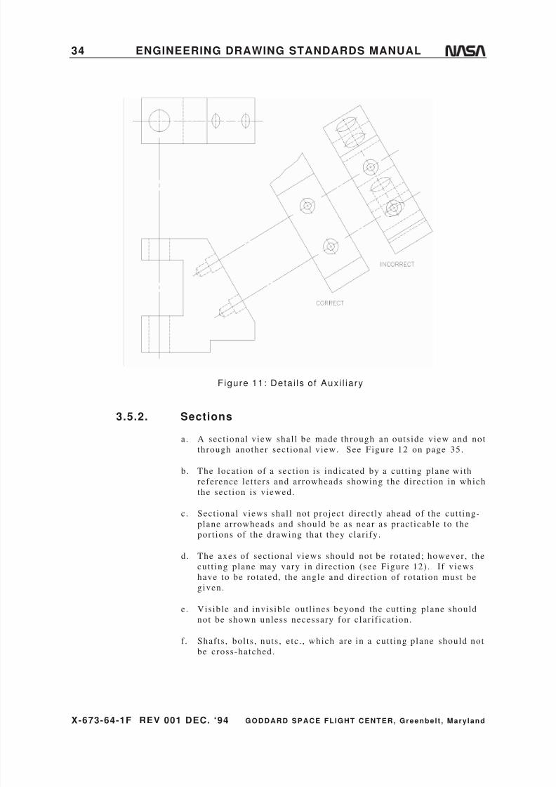
8/6/2019 Engineering Drawing Standards Manual GSFC-X-673!64!1F
http://slidepdf.com/reader/full/engineering-drawing-standards-manual-gsfc-x-673641f 46/128
X-673-64-1F REV 001 DEC. ‘94 GODDARD SPACE FLIGHT CENTER, Greenbelt , Mary land
34 ENGINEERING DRAWING STANDARDS MANUAL
Figure 11: Deta i ls o f Auxi l iary
3.5.2. Sections
a. A sect ional view shal l be made through an outside view and not
through another sect ional view. See Figure 12 on page 35.
b. The locat ion of a sect ion is indicated by a cut t ing plane with
reference let ters and arrowheads showing the direct ion in which
the sect ion is viewed.
c. Sect ional views shal l not project di rect ly ahead of the cut t ing-
plane arrowheads and should be as near as pract icable to the
port ions of the drawing that they clar i fy.
d. The axes of sect ional views should not be rotated; however , the
cut t ing plane may vary in direct ion (see Figure 12) . I f views
have to be rotated, the angle and direct ion of rotat ion must be
given.
e. Visible and invis ible out l ines beyond the cut t ing plane should
not be shown unless necessary for clar i f icat ion.
f . Shafts , bol ts , nuts , e tc . , which are in a cut t ing plane should not
be cross-hatched.
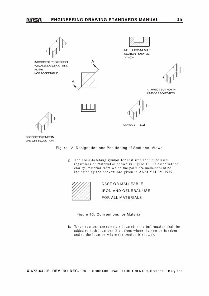
8/6/2019 Engineering Drawing Standards Manual GSFC-X-673!64!1F
http://slidepdf.com/reader/full/engineering-drawing-standards-manual-gsfc-x-673641f 47/128
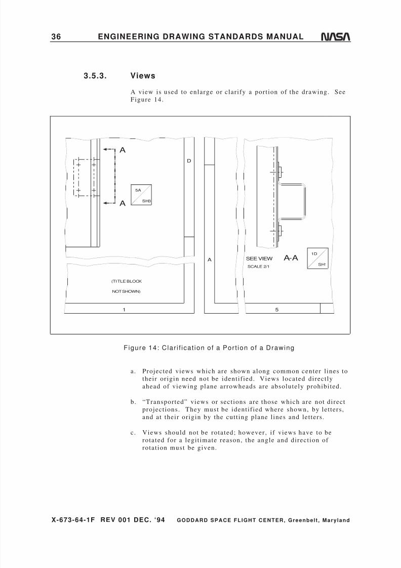
8/6/2019 Engineering Drawing Standards Manual GSFC-X-673!64!1F
http://slidepdf.com/reader/full/engineering-drawing-standards-manual-gsfc-x-673641f 48/128
X-673-64-1F REV 001 DEC. ‘94 GODDARD SPACE FLIGHT CENTER, Greenbelt , Mary land
36 ENGINEERING DRAWING STANDARDS MANUAL
3.5.3. Views
A view is used to enlarge or clar i fy a port ion of the drawing. See
Figure 14.
SEE VIEW
A
A
A-ASCALE 2/1
1D
SH1
5
A
D
1
SH3
5A
(TITLE BLOCK
NOT SHOWN)
Figure 14: Clar i f icat ion of a Por t ion of a Drawing
a. Projected views which are shown along common center l ines to
their or igin need not be ident i f ied. Views located direct ly
ahead of viewing plane arrowheads are absolutely prohibi ted.
b. “Transported” views or sect ions are those which are not direct
project ions. They must be ident i f ied where shown, by let ters ,
and at their or igin by the cut t ing plane l ines and let ters .
c . Views should not be rotated; however , i f views have to be
rotated for a legi t imate reason, the angle and direct ion of
rotat ion must be given.
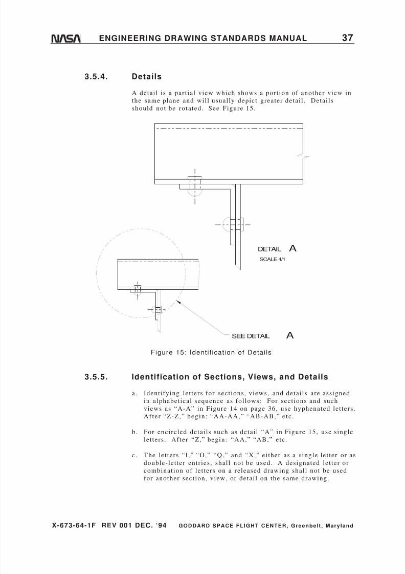
8/6/2019 Engineering Drawing Standards Manual GSFC-X-673!64!1F
http://slidepdf.com/reader/full/engineering-drawing-standards-manual-gsfc-x-673641f 49/128
X-673-64-1F REV 001 DEC. ‘94 GODDARD SPACE FLIGHT CENTER, Greenbelt , Mary land
ENGINEERING DRAWING STANDARDS MANUAL 37
3.5.4. Details
A detai l i s a par t ial view which shows a port ion of another view in
the same plane and wil l usual ly depict greater detai l . Detai lsshould not be rotated. See Figure 15.
DETAIL ASCALE 4/1
SEE DETAIL A
Figure 15: Ident i f icat ion of Detai ls
3.5.5. Identification of Sections, Views, and Details
a. Ident i fying let ters for sect ions, views, and detai ls are assigned
in alphabet ical sequence as fol lows: For sect ions and suchviews as “A-A” in Figure 14 on page 36, use hyphenated let ters .
Af te r “Z-Z,” begin : “AA-AA,” “AB-AB,” e tc .
b. For encircled detai ls such as detai l “A” in Figure 15, use s ingle
let ters . After “Z,” begin: “AA,” “AB,” etc .
c . The let ters “I ,” “O,” “Q,” and “X,” ei ther as a s ingle let ter or as
double- let ter entr ies , shal l not be used. A designated let ter or
combinat ion of let ters on a released drawing shal l not be used
for another sect ion, view, or detai l on the same drawing.

8/6/2019 Engineering Drawing Standards Manual GSFC-X-673!64!1F
http://slidepdf.com/reader/full/engineering-drawing-standards-manual-gsfc-x-673641f 50/128
X-673-64-1F REV 001 DEC. ‘94 GODDARD SPACE FLIGHT CENTER, Greenbelt , Mary land
38 ENGINEERING DRAWING STANDARDS MANUAL
3.5.6. Locating Sections, Views, and Details
On zoned and/or mult isheet drawings, a view, sect ion, or detai l and
the port ion of the drawing i t c lar i f ies shal l be cross-referenced asfol lows:
Reference on Original Drawing to
View on Clar i fying Sheet
Reference at View on Clar i fying
Sheet to Original Drawing
SEE VIEW A-A5A
SH3
VIEW A-ASCALE 4/1
1D
SH1
Note: Zone block s ize is 1/2- inch square.
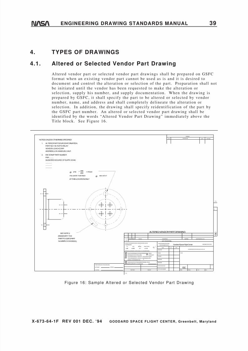
8/6/2019 Engineering Drawing Standards Manual GSFC-X-673!64!1F
http://slidepdf.com/reader/full/engineering-drawing-standards-manual-gsfc-x-673641f 51/128
X-673-64-1F REV 001 DEC. ‘94 GODDARD SPACE FLIGHT CENTER, Greenbelt , Mary land
ENGINEERING DRAWING STANDARDS MANUAL 39
4. TYPES OF DRAWINGS
4.1. Altered or Selected Vendor Part Drawing
Altered vendor par t or selected vendor par t drawings shal l be prepared on GSFC
format when an exis t ing vendor par t cannot be used as is and i t i s desired to
document and control the al terat ion or select ion of the par t . Preparat ion shal l not
be ini t iated unt i l the vendor has been requested to make the al terat ion or
select ion, supply his number , and supply documentat ion. When the drawing is
prepared by GSFC, i t shal l specify the par t to be al tered or selected by vendor
number, name, and address and shal l completely del ineate the al terat ion or
select ion. In addi t ion, the drawing shal l specify reident i f icat ion of the par t by
the GSFC part number . An al tered or selected vendor par t drawing shal l be
ident i f ied by the words “Altered Vendor Par t Drawing” immediately above the
Tit le block. See Figure 16.
NOTES: UNLESSOTHERWISESPECIFIED
1. ALTEREDPART SOURCEINFORMATION;
PART NO: 118-R-0715 RELAY
VENDOR; LEACHCORP.
ADDRESS; LOSANGELES, CALIF.
ALTERED VENDOR PART DRAWINGSEE NOTE2
(REIDENTIFYTHE
PART TOGSFCPART
ø .218 +-
.006
.000-1 HOLE
ENLARGEEXISTING
AT THISLOCATIONONLY
ø .166 HOLE
2. INK STAMP PART NUMBER
PER..........
SUGESTEDSOURCEOF SUPPLY(INK)
...............
...............
...............
NUMBERGCXXXXXXX.)
REV
R E V
DATE APPROVAL
F O L D
L I N E
G C
GREENBELT,MARYLAND
SH
DESCRIPTION
REVISION
MATERIAL
Goddard Space Flight Center
WTSCALE
DRAWINGINTERPRETEDPERGSFC-X673 -64-1
MATERIALSPEC& NO.PARTNO.
HARDNESSTESTNOTREQUIRED
REMOVEALLBURRSAND SHARPEDGESR. 010ORCHAMFERMAX.
UNLESSOTHERWISESPECIFIED-DI MENSIONSAREIN INCHES
TESTHARDNESSPER ASTME-18, LOCATIONOPTIONAL
TESTHARDNESSPER ASTME-18 WHEREINDICATED
ONFIELD OFDRAWINGTHUS
NONON-DESTRUCTIVEEXAMINATION(NDE) REQ'D
NDEREQUIREDPER S-313-009CODETHISDRAWINGWAS PRODUCEDUSING
SOFTWARE:
FILENAME:
VERSION:
TOLERANCES:
FLIGHTHARDWARE/POSTFABHARDNESSTEST REQ'D
F O L D
L I N E
.XX
ITEM
NO.
NEXTASSY
.XXX
REQ'DREQ'D
NAME
LISTOFMATERIAL
NATIONALAERONAUTICSAND
SPACEADMINISTRATION
DESCRIPTION
APPROVED-STRESS
APPROVED-ENGINEER
NONFLIGHT
USEDON
FRACTIONS
±1/16
APPROVED
DESIGNER
DRAWN
CHECKED
APPROVED
125DATEINIT
CODE
TITLE
SYM
GC
±.02 ±.005 ±1°
Figure 16: Sample Altered or Selected Vendor Part Drawing

8/6/2019 Engineering Drawing Standards Manual GSFC-X-673!64!1F
http://slidepdf.com/reader/full/engineering-drawing-standards-manual-gsfc-x-673641f 52/128
X-673-64-1F REV 001 DEC. ‘94 GODDARD SPACE FLIGHT CENTER, Greenbelt , Mary land
40 ENGINEERING DRAWING STANDARDS MANUAL
4.2. Assembly Drawing
An assembly drawing shows two or more separable par ts joined to form astockable i tem, or a group of assemblies required to form an assembly of higher
order . Figure 17 shows an example of an assembly drawing when a separate par ts
l is t i s required. Figure 34, “Assembly Drawing With List of Mater ial ,” on
page 80, shows an assembly drawing with the List of Mater ial on the drawing.
Refer also to Sect ion 5.1, “Part Numbering,” on page 61.
MS15795-30510
9 MS35234-17
11 MS35649-44
MS35649-638
GXXXXXX11
7 MS15795-305
2GXXXXXX5
GXXXXXX63
GXXXXXX34
GXXXXXX45
GXXXXXX26
2X
2X
2X
4X
2X
REV
R E V
DATE APPROVAL
F O L D
L I N E
G C
GREENBELT,MARYLAND
SH
DESCRIPTION
REVISION
MATERIAL
Goddard Space Flight Center
WTSCALE
DRAWINGINTERPRETEDPERGSFC-X673 -64-1
MATERIALSPEC& NO.PARTNO.
HARDNESSTESTNOT REQUIRED
REMOVEALLBURRSAND SHARPEDGESR. 010ORCHAMFERMAX.
UNLESSOTHERWISESPECIFIED-DIMENSIONS AREIN INCHES
TESTHARDNESSPER ASTME-18, LOCATIONOPTIONAL
TESTHARDNESSPER ASTME-18 WHEREINDICATED
ONFIELD OFDRAWINGTHUS
NONON-DESTRUCTIVEEXAMINATION(NDE) REQ'D
NDEREQUIREDPER S-313-009CODETHISDRAWINGWAS PRODUCEDUSING
SOFTWARE:
FILE NAME:
VERSION:
TOLERANCES:
FLIGHTHARDWARE/POSTFABHARDNESSTEST REQ'D
F O L D
L I N E
.XX
ITEM
NO.
NEXTASSY
.XXX
REQ'DREQ'D
NAME
LISTOFMATERIAL
NATIONALAERONAUTICSAND
SPACEADMINISTRATION
DESCRIPTION
APPROVED-STRESS
APPROVED-ENGINEER
NONFLIGHT
USEDON
FRACTIONS
±1/16
APPROVED
DESIGNER
DRAWN
CHECKED
APPROVED
125DATEINIT
CODE
TITLE
SYM
GC
±.02 ±.005 ±1°
Figure 17: Sample Assembly Drawing

8/6/2019 Engineering Drawing Standards Manual GSFC-X-673!64!1F
http://slidepdf.com/reader/full/engineering-drawing-standards-manual-gsfc-x-673641f 53/128
X-673-64-1F REV 001 DEC. ‘94 GODDARD SPACE FLIGHT CENTER, Greenbelt , Mary land
ENGINEERING DRAWING STANDARDS MANUAL 41
4.3. Detail Drawing
A detai l drawing shows al l the information necessary for fabr icat ing an i tem,including the mater ial f rom which i t i s made and those f inishes, protect ive
coat ings, and processes required to fabr icate the end product . Only one i tem
(detai l par t ) shal l be presented per drawing. See Figure 18.
1.120
.750
1.000
NOTES: UNLESSOTHERWISESPECIFIED
.500O
2.250
1.500
1. IRIDITEINACCORDANCEWITH
MIL-C-5541. CLASS1A.
RUBBERSTAMP.125 HIGH CHARACTERS
ASSHOWNUSING____________.
2
ORIGINAL SOURCEOF SUPPLY:
INSERT COMPLETE
_________
ADDRESS _________
BAR ALALY QQ-A-225/8 6061-T6
REV
R E V
DATE APPROVAL
F O L D
L I N E
G C
GREENBELT,MARYLAND
SH
DESCRIPTION
REVISION
MATERIAL
GoddardSpace Flight Center
WTSCALE
DRAWINGINTERPRETEDPERGSFC-X673-6 4-1
MATERIALSPEC& NO.PARTNO.
HARDNESSTESTNOTREQUIRED
REMOVEALLBURRSANDSHARPEDGESR .010 ORCHAMFERMAX.
UNLESSOTHERWISESPECIFIED-DIMENSIONSAREI NINCHES
TESTHARDNESSPERASTME-18, LOCATIONOPTIONAL
TESTHARDNESSPERASTME-18 WHEREINDICATED
ONFIELD OFDRAWINGTHUS
NONON-DESTRUCTIVEEXAMINATION(NDE) REQ'D
NDEREQUIREDPER S-313-009CODETHISDRAWINGWASPRODUCEDUSING
SOFTWARE:
FILE NAME:
VERSION:
TOLERANCES:
FLIGHTHARDWARE/POSTFABHARDNESSTESTREQ'D
F O L D
L I N E
.XX
ITEM
NO.
NEXTASSY
.XXX
REQ'DREQ'D
NAME
LISTOF MATERIAL
NATIONALAERONAUTICSAND
SPACEADMINISTRATION
DESCRIPTION
APPROVED-STRESS
APPROVED-ENGINEER
NONFLIGHT
USEDON
FRACTIONS
±1/16
APPROVED
DESIGNER
DRAWN
CHECKED
APPROVED
125DATEINIT
CODE
TITLE
SYM
GC
±.02 ±.005 ±1°
Figure 18: Sample Deta i l Drawing
In the case of inseparable par ts (such as those that are welded, r iveted, bonded, or
brazed, etc .) which form an integral uni t (par t ) not capable of being disassembled
for replacement , refer to paragraph 4.6 ent i t led “Inseparable Assembly Drawing”
on page 44 .
Mult idetai l drawings are not al lowed. The GSFC requires a unique drawing
number per par t so that each par t can be individual ly est imated by fabricators and
ident i f ied for inspect ion and configurat ion t racking.
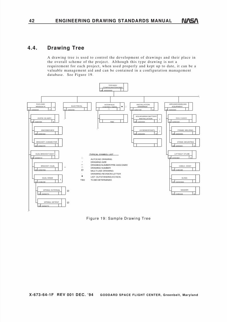
8/6/2019 Engineering Drawing Standards Manual GSFC-X-673!64!1F
http://slidepdf.com/reader/full/engineering-drawing-standards-manual-gsfc-x-673641f 54/128
X-673-64-1F REV 001 DEC. ‘94 GODDARD SPACE FLIGHT CENTER, Greenbelt , Mary land
42 ENGINEERING DRAWING STANDARDS MANUAL
4.4. Drawing Tree
A drawing t ree is used to control the development of drawings and their place inthe overal l scheme of the project . Al though this type drawing is not a
requirement for each project , when used properly and kept up to date, i t can be a
valuable management aid and can be contained in a configurat ion management
database. See Figure 19.
TOP ASSY
CONFIGURATION DWG
GE -XXXXXXX
2456000
4,5
CGJ
MODULE-A
PAYLOAD
2456050 AGF
AVIONICS ASSY
2456042 -GE
ENCODER BOX
2456070 -GD
BRACKET, CONNECTOR
2456010
1
-GE
DUAL BRACKET ASSY
2456789GD
BRACKET, DUAL
2456273GC
SPRING, EXTERNAL
2456272GC
SPRING, DETENT
ELECTRICAL
GJ -2450200
GE 2456290
DUAL HINGE
-
TBD
INTERFACE
CONTROL DWGS
* - AGJ
DRAWINGS
INSTALLATION
UV SENSOR INSTL
GD D2452250
2452100
INSTALLATION
SOLAR ARRAY BATTERY
2452200GE -
2
7
-
SLING
24550362GF
CABLE, HOIST
GD 2450365
LIFTING FI XTURE
GE A2450360
STAND, MOUNTING
GE C2450351
FRAME, WELDING
GE -2450350
DOLLY ASSY
GJ -2450330
GROUND HANDLING
EQUIPMENT
GE -2450300
-
BGC 2450424
WASHER
AUTOCAD DRAWING
DRAWING SIZE
DRAWING NUMBER PRE-ASSIGNED
DRAWING NUMBER
MULTI-USE DRAWING
DRAWING REVISION LETTER
TO BE DETERMINED
LIST OUTSTANDING EO NOS.
**
*
-
TBD
TYPICAL SYMBOL LIST
**
3
Figure 19: Sample Drawing Tree

8/6/2019 Engineering Drawing Standards Manual GSFC-X-673!64!1F
http://slidepdf.com/reader/full/engineering-drawing-standards-manual-gsfc-x-673641f 55/128
X-673-64-1F REV 001 DEC. ‘94 GODDARD SPACE FLIGHT CENTER, Greenbelt , Mary land
ENGINEERING DRAWING STANDARDS MANUAL 43
4.5. Electrical/Electronic Drawings
Electr ical /electronic drawings are prepared to depict schematics , wir ing diagrams,cable interconnect ions, and detai led cable assembly drawings.
4.5.1. Electrical and Electronic Symbols
Applicat ion: Symbols shal l be in accordance with ANSI Y32.2-
1975, Graphic Symbols for Electr ical and Electronic Diagrams (or
later revis ions) , unless otherwise noted.
Graphic electr ical wir ing symbols for archi tectural and electr ical
layout drawings shal l conform to ANSI Y32.9-1972, Graphic
Symbols for Electr ical Wiring and Layout Diagrams Used in
Archi tecture and Bui lding Construct ion (or later revis ions) .
4.5.2. Electrical and Electronic Diagrams
Applicat ion: Diagrams shal l be in accordance with ANSI Y14.15-
1966 (R-73) Electr ical and Electronic Diagrams (or later
revi s ions) ; ANSI Y14.15a-1971, Interconnect ion Diagrams,
subsec t ion 15-11; ANSI Y14.15b-1973, Electr ical and Electronics
Diagrams, subsec t ions 15-1 through 15-10, and 15-12.

8/6/2019 Engineering Drawing Standards Manual GSFC-X-673!64!1F
http://slidepdf.com/reader/full/engineering-drawing-standards-manual-gsfc-x-673641f 56/128
X-673-64-1F REV 001 DEC. ‘94 GODDARD SPACE FLIGHT CENTER, Greenbelt , Mary land
44 ENGINEERING DRAWING STANDARDS MANUAL
4.6. Inseparable Assembly Drawing
An inseparable assembly drawing del ineates i tems (pieces) which are separatelyfabricated and are permanent ly joined together (e .g. , welded, brazed, r iveted,
nai led, bonded, etc .) to form an integral uni t (par t ) not capable of being readi ly
disassembled. An inseparable assembly drawing may be prepared in l ieu of
individual monodetai l drawings for inseparable assemblies intended to be
procured and replaced as a uni t , where (except for s tandard hardware) the
separate par ts are of s imilar or compat ible mater ials . See Figure 20 (al l data,
such as notes and l is t of mater ial , are not shown).
.750
1.000
.250 TYP
R.125
.063
1.000
GXXXXXX2 1
.875
1.250
1.960 .063
MS20426-X3
MS33588-X2
4.000
3.500 .250
.063
ø .125+-
.006
.0002X
REV
R E V
DATE APPROVAL
F O L D
L I N E
G C
GREENBELT,MARYLAND
SH
DESCRIPTION
REVISION
MATERIAL
Goddard Space Flight Center
WTSCALE
DRAWINGINTERPRETEDPERGSFC-X673 -64-1
MATERIALSPEC& NO.PARTNO.
HARDNESSTESTNOT REQUIRED
REMOVEALLBURRSAND SHARPEDGESR. 010 ORCHAMFERMAX.
UNLESSOTHERWISESPECIFIED-DI MENSIONSAREIN INCHES
TESTHARDNESSPER ASTME-18, LOCATIONOPTIONAL
TESTHARDNESSPERASTME-18 WHEREINDICATED
ONFIELDOFDRAWINGTHUS
NONON-DESTRUCTIVEEXAMINATION(NDE) REQ'D
NDEREQUIREDPER S-313-009 CODETHISDRAWINGWAS PRODUCEDUSING
SOFTWARE:
FILENAME:
VERSION:
TOLERANCES:
FLIGHTHARDWARE/POSTFABHARDNESSTEST REQ'D
F O L D
L I N E
.XX
ITEM
NO.
NEXTASSY
.XXX
REQ'DREQ'D
NAME
LISTOFMATERIAL
NATIONALAERONAUTICSAND
SPACEADMINISTRATION
DESCRIPTION
APPROVED-STRESS
APPROVED-ENGINEER
NONFLIGHT
USEDON
FRACTIONS
±1/16
APPROVED
DESIGNER
DRAWN
CHECKED
APPROVED
125DATEINIT
CODE
TITLE
SYM
GC
±.02 ±.005 ±1°
Figure 20: Sample Inseparable Assembly Drawing
An inseparable assembly drawing shal l ful ly def ine the end product or detai l
assembly as assembled. Pieces of the inseparable assembly may be detai led ei ther
on separate detai l drawings or on the inseparable assembly drawing i tsel f . In the
case of weldments , the par ts shal l not be individual ly detai led on separate
drawings (due to the consumable mater ial al lowances that would have to be shown
on detai l drawings) , except in cases where extensive machining might be
necessary.
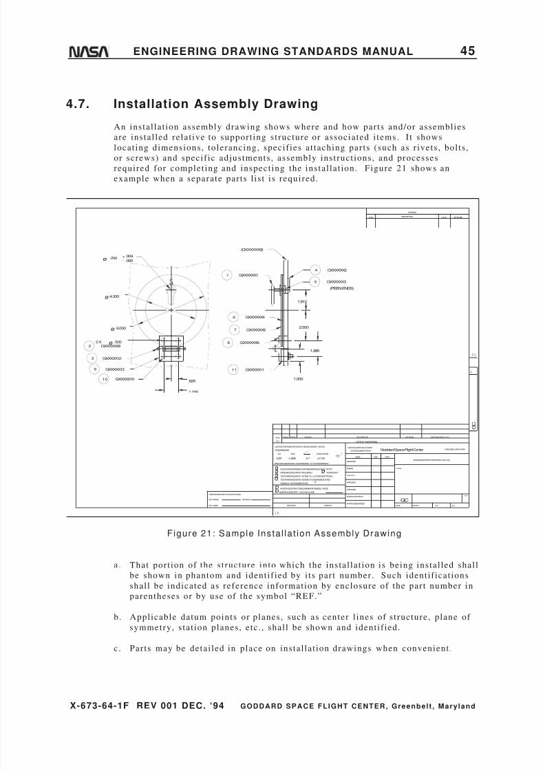
8/6/2019 Engineering Drawing Standards Manual GSFC-X-673!64!1F
http://slidepdf.com/reader/full/engineering-drawing-standards-manual-gsfc-x-673641f 57/128
X-673-64-1F REV 001 DEC. ‘94 GODDARD SPACE FLIGHT CENTER, Greenbelt , Mary land
ENGINEERING DRAWING STANDARDS MANUAL 45
4.7. Installation Assembly Drawing
An instal lat ion assembly drawing shows where and how parts and/or assemblies
are instal led relat ive to support ing s t ructure or associated i tems. I t showslocat ing dimensions, tolerancing, specif ies at taching par ts (such as r ivets , bol ts ,
or screws) and specif ic adjustments , assembly inst ruct ions, and processes
required for complet ing and inspect ing the instal lat ion. Figure 21 shows an
example when a separate par ts l is t i s required.
REV
R E V
DATE APPROVAL
F O L D
L I N E
G C
GREENBELT,MARYLAND
SH
DESCRIPTION
REVISION
MATERIAL
Goddard Space Flight Center
WTSCALE
DRAWINGINTERPRETEDPERGSFC-X673 -64-1
MATERIALSPEC& NO.PARTNO.
HARDNESSTESTNOT REQUIRED
REMOVEALLBURRSAND SHARPEDGESR. 010ORCHAMFERMAX.
UNLESSOTHERWISESPECIFIED-DI MENSIONSAREIN INCHES
TESTHARDNESSPERASTME-18, LOCATIONOPTIONAL
TESTHARDNESSPERASTME-18 WHEREINDICATED
ONFIELD OFDRAWINGTHUS
NONON-DESTRUCTIVEEXAMINATION(NDE) REQ'D
NDEREQUIREDPER S-313-009 CODETHISDRAWINGWAS PRODUCEDUSING
SOFTWARE:
FILE NAME:
VERSION:
TOLERANCES:
FLIGHTHARDWARE/POSTFABHARDNESSTEST REQ'D
F O L D
L I N E
.XX
ITEM
NO.
NEXTASSY
.XXX
REQ'DREQ'D
NAME
LISTOF MATERIAL
NATIONALAERONAUTICSAND
SPACEADMINISTRATION
DESCRIPTION
APPROVED-STRESS
APPROVED-ENGINEER
NONFLIGHT
USEDON
FRACTIONS
±1/16
APPROVED
DESIGNER
DRAWN
CHECKED
APPROVED
125DATEINIT
CODE
TITLE
SYM
GC
±.02 ±.005 ±1°
.000
.004-+.250ø
6.000ø
4.300ø
GXXXXX12
GXXXXX10
GXXXXX139
3
.625
1.150
GXXXXXX11
GXXXXXX82
GXXXXXX46
(GXXXXXX9)
ø .5002 X
GXXXXXX57
GXXXXXX68
GXXXXX1111
1.000
1.812
2.500
1.380
GXXXXXX35
4 GXXXXXX2
(PEENENDS)
10
Figure 21: Sample Insta l la t ion Assembly Drawing
a. That port ion of the s t ructure into which the instal lat ion is being instal led shal l
be shown in phantom and ident i f ied by i ts par t number . Such ident i f icat ions
shal l be indicated as reference information by enclosure of the par t number in
parentheses or by use of the symbol “REF.”
b. Appl icable datum points or planes, such as center l ines of s t ructure, plane of
symmetry, s tat ion planes, etc . , shal l be shown and ident i f ied.
c . Par ts may be detai led in place on instal lat ion drawings when convenient .

8/6/2019 Engineering Drawing Standards Manual GSFC-X-673!64!1F
http://slidepdf.com/reader/full/engineering-drawing-standards-manual-gsfc-x-673641f 58/128
X-673-64-1F REV 001 DEC. ‘94 GODDARD SPACE FLIGHT CENTER, Greenbelt , Mary land
46 ENGINEERING DRAWING STANDARDS MANUAL
4.8. Interface Control Drawing
An interface control drawing shal l be used to maintain compat ibi l i ty of al lphysical and funct ional designs between different engineer ing design act ivi t ies .
The drawing shal l communicate design cr i ter ia such as dimensions, hole and/or
bol t s izes , hardware, and ul t imate changes relat ive to cofunct ioning systems.
“Interface Control Drawing” shal l be added direct ly above the Ti t le block. No
l is t of mater ials is permit ted on this ty pe of drawing; i t i s no t to be used to
manufacture par ts . See Figures 22a, below, and 22b on page 48.
23.250
15.500
7.750
3.000
6.000
9.000
12.000
24.000
+Y
+Z
12 x ø.281±.004
.000
ø.007
23°-30'+Y
PLATFORM#5
REF
VIEWLOOKINGOUTBOARD
INTERFACE CONTROL DRAWING
NOTES: UNLESSOTHERWISESPECIFIED
7.000
A-ASECTION
-A-
A A
M A B C
1.500
.375
1 SUPPLIEDBY XZ CORP.
2 THISDRAWINGIS NOT TO
BEUSEDFORFABRICATION
ORINSPECTION.
1
-C-
-B-
CONTROL BOX#5
REV
R E V
DATE APPROVAL
F O L D
L I N E
G C
GREENBELT,MARYLAND
SH
DESCRIPTION
REVISION
MATERIAL
Goddard Space Flight Center
WTSCALE
DRAWINGINTERPRETEDPERGSFC-X673 -64-1
MATERIALSPEC& NO.PARTNO.
HARDNESSTESTNOTREQUIRED
REMOVEALLBURRSAND SHARPEDGESR. 010 ORCHAMFERMAX.
UNLESSOTHERWISESPECIFIED-DI MENSIONSAREIN INCHES
TESTHARDNESSPER ASTME-18, LOCATIONOPTIONAL
TESTHARDNESSPERASTME-18 WHEREINDICATED
ONFIELDOFDRAWINGTHUS
NONON-DESTRUCTIVEEXAMINATION(NDE) REQ'D
NDEREQUIREDPER S-313-009CODETHISDRAWINGWAS PRODUCEDUSING
SOFTWARE:
FILENAME:
VERSION:
TOLERANCES:
FLIGHTHARDWARE/POSTFABHARDNESSTEST REQ'D
F O L D
L I N E
.XX
ITEM
NO.
NEXTASSY
.XXX
REQ'DREQ'D
NAME
LISTOFMATERIAL
NATIONALAERONAUTICSAND
SPACEADMINISTRATION
DESCRIPTION
APPROVED-STRESS
APPROVED-ENGINEER
NONFLIGHT
USEDON
FRACTIONS
±1/16
APPROVED
DESIGNER
DRAWN
CHECKED
APPROVED
125DATEINIT
CODE
TITLE
SYM
GC
±.02 ±.005 ±1°
BOSS, CT06132
12 WATERLANE
Figure 22a: Sample Inter face Control Drawing

8/6/2019 Engineering Drawing Standards Manual GSFC-X-673!64!1F
http://slidepdf.com/reader/full/engineering-drawing-standards-manual-gsfc-x-673641f 59/128
X-673-64-1F REV 001 DEC. ‘94 GODDARD SPACE FLIGHT CENTER, Greenbelt , Mary land
ENGINEERING DRAWING STANDARDS MANUAL 47
4 . 0 0 F O R P A L L E T
A N D R O L L E R S
W L 1 4 0 . 0 0 C 5 A
9 . 5 6 2 A T T E N . F R .
Z 3 0 0 . 7 6 R E F
4 3 . 5 2 6
6 . 9 3 S P A C E R
7 5 . 9 1 4
9 . 3 8 8 A D A P T E R
5 . 0 0
Z 4 0 0
R E M O V A B L E
S U P P O R T
S T R U T
6 8 . 5 2 4
I N C L U D I N G
C O V E R S
W L 3 0 2 . 0 0 C 5 A
4 . 0 0
5 5 . 1 6 2
Z 4 1 4
T U R N O V E R
A X I S
3 1 . 8 3 9
M M S
R 1 0 1 . 4 3 1 Ø
1 9 0 . 0 0
6 5 . 2 3 9
5 2 . 9 1 4
T R U N N I O N
C O V E R
3 6 . 3 6 1
4 . 3 9
N O T E 1 L O
A D
C E L L
J A C K S
P A C E R
S L O T T E D
1 . 0 0
1 0 4 . 3 1 4 F O R T U R N O V E R M O T I O N ( S H O W N )
1 0 5 . 3 1 4 F O R T U R N O V E R E Q U I P M E N T I N S T A L L A T I O N
1 0 2 . 3 1 4 F O R S T A T I C S U P P O R T O N P O S T S
4 6 . 8 3
4 8 . 0 0
6 9 . 7 5
4 9 . 0 1 3
H I N G E
P O I N T
7 . 0 0
1 . 5
1 7 . 3 7 5
4 7 . 9 0 2
4 6 . 8 3
2 . 0 7 2
U A R I N
T U R N
O V E R
C 5 A S H I P P I N G
C O N F I G U R A T I O N
S I D E V I E W
N O T E S : U N L E S S O T H E R W I S E S P E C I F
I E D
1 .
S U P P O R T P O S T S F O L D A W A Y F
O R T U R N O V E R
A N D R E M O V E F O R S H I P P I N G .
Z 4 1 4
1 6 . 1 7
1 . 0
1 1 . 1 7
M P F
G C
L I S T O F M A T E R I A L
N A T I O N A L A E R O N A U T I C S A N D
S P A C E A D M I N I S T R A T I O N
R E Q D
T O L E R A N C E S :
F L I G H T H A R D W A R E
N E X T A S S Y
H A R D N E S S T E S T N O T R E Q U I R E D
O N F I E L D O F D R A W I N G T H U S
N D E R E Q U I R E D P E R S - 3 1 3 - 0 0 9 C O D E
T E S T H A R D N E S S P E R A S T M E - 1 8 , L O C A T I O N O P T I O N A L
T E S T H A R D N E S S P E R A S T M E - 1 8 W H E R E I N D I C A T E D
N O N O N - D E S T R U C T I V E E X A M I N A T I O N ( N D E ) R E Q ' D
R E M O V E A L L B U R R S A N D S H A R P E D G E S R . 0 1 0 O R C H A M F E R M A X .
U N L E S S O T H E R W I S E S P E C I F I E D - D I M E N S I O N S A R E I N I N C H E S
F I L E N A M E :
S O F T W A R E :
V E R S I O N :
F O L D
L I N E
T H I S D R A W I N G W A S P R O D U C E D U S I N G
. X X
I T E M
N O .
U S E D O N
A P P R O V E D - S T R E S S
A P P R O V E D - E N G I N E E R
N O N F L I G H T
F R A C T I O N S
± 1 / 1 6
P A R T N O .
. X X X
D E S I G N E R
D R A W N
C H E C K E D
A P P R O V E D
A P P R O V E D
1 2 5
N A M E
D E S C R I P T I O N
G R E E N
B E L T , M A R Y L A N D
D R A W I N G I N T E R P R E T E D P E R G S F C - X 6 7 3 - 6 4 - 1
S C A L E
C O D E
W T
S H
G o d d a r d S p a c e F l i g h t C e n t e r
T I T L E
I N I T
D A T E
M A T E R I A L
M A T E R I A L S P E C & N O .
R E V
S Y M
L I N E
F O L D
R E V
A P P R O V A L
D E S C R I P T I O N
D A T E
R E V I S I O N
G C
± . 0 2
± . 0 0 5
± 1 °
/ P O S T F A B H A R D N E S S T E S T R E Q ' D
I N T E R F A C E C O N T R O L D R A W I N G
P O S
I T I O N
R E Q D

8/6/2019 Engineering Drawing Standards Manual GSFC-X-673!64!1F
http://slidepdf.com/reader/full/engineering-drawing-standards-manual-gsfc-x-673641f 60/128
X-673-64-1F REV 001 DEC. ‘94 GODDARD SPACE FLIGHT CENTER, Greenbelt , Mary land
48 ENGINEERING DRAWING STANDARDS MANUAL
Figure 22b: Sample Inter face Control DrawingNote: Format is too small . No informat ion should appear beneath revision block
or above l ist of mater ial. Choose a larger format in this case.
4.9. Matched-Set Drawing
A matched-set drawing depicts par ts that are machine-matched or otherwise mated
and for which replacement as a matched set or pair is essent ial . The operat ing or
mating character is t ics of the matched par ts (set ) shal l be indicated. The par ts
shal l be uniquely marked with a ser ial number ident i f icat ion to indicate a matched
set . See Figure 23 (al l data required for the f inished drawing are not shown).
The drawing t i t le becomes an assembly, al though the par ts are not actual ly
at tached. “Maintain and Furnish Only As A Matched Set” shal l be added direct ly
above the Ti t le block or List of Mater ial .
REV
R E V
DATE APPROVAL
F O L D
L I N E
G C
GREENBELT,MARYLAND
SH
DESCRIPTION
REVISION
MATERIAL
Goddard Space Flight Center
WTSCALE
DRAWINGINTERPRETEDPERGSFC-X673 -64-1
MATERIALSPEC& NO.PARTNO.
HARDNESSTESTNOT REQUIRED
REMOVEALLBURRSAND SHARPEDGESR. 010ORCHAMFERMAX.
UNLESSOTHERWISESPECIFIED-DI MENSIONSAREIN INCHES
TESTHARDNESSPERASTME-18, LOCATIONOPTIONAL
TESTHARDNESSPER ASTME-18 WHEREINDICATED
ONFIELD OFDRAWINGTHUS
NONON-DESTRUCTIVEEXAMINATION(NDE) REQ'D
NDEREQUIREDPER S-313-009 CODETHISDRAWINGWAS PRODUCEDUSING
SOFTWARE:
FILE NAME:
VERSION:
TOLERANCES:
FLIGHTHARDWARE/POSTFABHARDNESSTEST REQ'D
F O L D
L I N E
.XX
ITEM
NO.
NEXTASSY
.XXX
REQDREQD
NAME
LISTOF MATERIAL
NATIONALAERONAUTICSAND
SPACEADMINISTRATION
DESCRIPTION
APPROVED-STRESS
APPROVED-ENGINEER
NONFLIGHT
USEDON
FRACTIONS
±1/16
APPROVED
DESIGNER
DRAWN
CHECKED
APPROVED
125
DATEINIT
CODE
TITLE
SYM
GC
±.02 ±.005 ±1°
3 GXXXXXX3
GXXXXXX22
1 GXXXXXX1
LAP.00008 TO.00015
DIAMETRAL CLEARANCE
MAINTAIN AND FURNISH ONLY AS A MATCHED SET
Figure 23: Sample Matched-Set Drawing

8/6/2019 Engineering Drawing Standards Manual GSFC-X-673!64!1F
http://slidepdf.com/reader/full/engineering-drawing-standards-manual-gsfc-x-673641f 61/128
X-673-64-1F REV 001 DEC. ‘94 GODDARD SPACE FLIGHT CENTER, Greenbelt , Mary land
ENGINEERING DRAWING STANDARDS MANUAL 49
4.10. Mechanical Schematic
A mechanical schematic diagram drawing i l lust rates the operat ional sequence orarrangement of a mechanical device. Dimensions and relat ive s izes of i tems may
be shown to indicate mechanical relat ionship. See Figure 24.
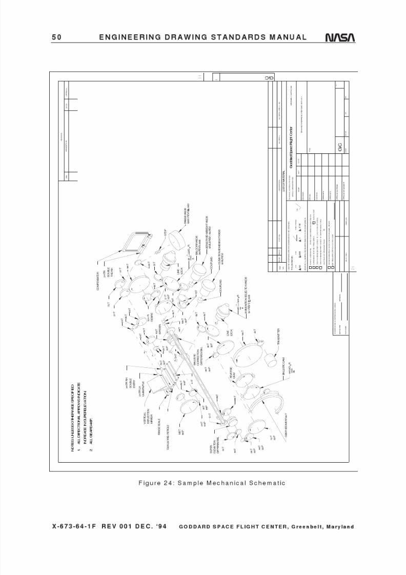
8/6/2019 Engineering Drawing Standards Manual GSFC-X-673!64!1F
http://slidepdf.com/reader/full/engineering-drawing-standards-manual-gsfc-x-673641f 62/128
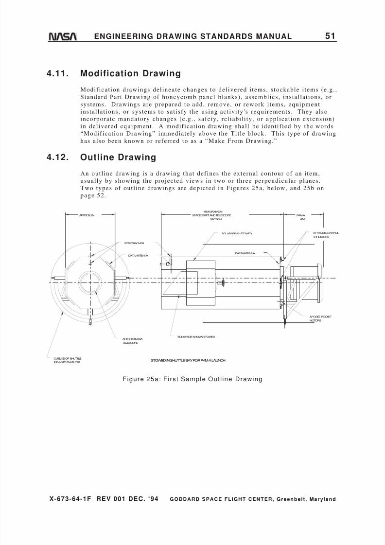
8/6/2019 Engineering Drawing Standards Manual GSFC-X-673!64!1F
http://slidepdf.com/reader/full/engineering-drawing-standards-manual-gsfc-x-673641f 63/128
X-673-64-1F REV 001 DEC. ‘94 GODDARD SPACE FLIGHT CENTER, Greenbelt , Mary land
ENGINEERING DRAWING STANDARDS MANUAL 51
4.11. Modification Drawing
Modif icat ion drawings del ineate changes to del ivered i tems, s tockable i tems (e.g. ,
Standard Part Drawing of honeycomb panel blanks) , assemblies , instal lat ions, orsystems. Drawings are prepared to add, remove, or rework i tems, equipment
instal lat ions, or systems to sat isfy the using act ivi ty 's requirements . They also
incorporate mandatory changes (e .g. , safety, rel iabi l i ty, or appl icat ion extension)
in del ivered equipment . A modif icat ion drawing shal l be ident i f ied by the words
“Modif icat ion Drawing” immediately above the Ti t le block. This type of drawing
has also been known or referred to as a “Make From Drawing.”
4.12. Outline Drawing
An out l ine drawing is a drawing that def ines the external contour of an i tem,
usual ly by showing the projected views in two or three perpendicular planes.
Two types of out l ine drawings are depicted in Figures 25a, below, and 25b onpage 52 .
APPROX 3M SPACECRAFT ANDTELESCOPE PAM-A
15MMAXIMUM
SECTION 3M
STARTRACKER
DATAANTENNA
APPROX1MDIA
OUTLINE OF SHUTTLE
TELESCOPE
PAYLOADENVELOPE
DATAANTENNA
SOLARARRAYSTOWED
SUNSHADESHOWNSTOWED
ATTITUDECONTROL
THRUSTERS
APOGEEROCKET
MOTORS
STOWED IN SHUTTLE BAY FOR PAM-A LAUNCH
Figure 25a: F i rs t Sample Out l ine Drawing

8/6/2019 Engineering Drawing Standards Manual GSFC-X-673!64!1F
http://slidepdf.com/reader/full/engineering-drawing-standards-manual-gsfc-x-673641f 64/128
X-673-64-1F REV 001 DEC. ‘94 GODDARD SPACE FLIGHT CENTER, Greenbelt , Mary land
52 ENGINEERING DRAWING STANDARDS MANUAL
SHUTTLE TRANSPORTATION SYSTEM
PAYLOAD
INSTALLATIONSATELLITE
COBE
576.00584.00
760.50
943.50
1123.50
217.22
SPACECRAFT LENGTH1108.33
1069.00
1307.001305.50
96.68
SOLAR ARRAY PANELS
207.06
186.00
+X Looking aft
+Y
+Z Looking out of
the plane of pape
-Y
Figure 25b: Second Sample Out l ine Drawing
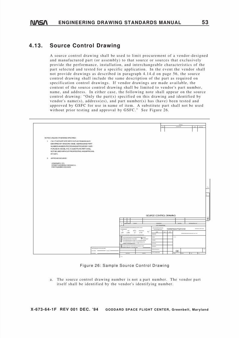
8/6/2019 Engineering Drawing Standards Manual GSFC-X-673!64!1F
http://slidepdf.com/reader/full/engineering-drawing-standards-manual-gsfc-x-673641f 65/128
X-673-64-1F REV 001 DEC. ‘94 GODDARD SPACE FLIGHT CENTER, Greenbelt , Mary land
ENGINEERING DRAWING STANDARDS MANUAL 53
4.13. Source Control Drawing
A source control drawing shal l be used to l imit procurement of a vendor-designed
and manufactured par t (or assembly) to that source or sources that exclusivelyprovide the performance, instal lat ion, and interchangeable character is t ics of the
part selected and tested for a specif ic appl icat ion. In the event the vendor shal l
not provide drawings as descr ibed in paragraph 4.14.d on page 56, the source
control drawing shal l include the same descr ipt ion of the par t as required on
specif icat ion control drawings. I f vendor drawings are made avai lable, the
content of the source control drawing shal l be l imited to vendor 's par t number ,
name, and address . In ei ther case, the fol lowing note shal l appear on the source
control drawing: “Only the par t (s) specif ied on this drawing and ident i f ied by
vendor 's name(s) , address(es) , and par t number(s) has (have) been tested and
approved by GSFC for use in name of i tem. A subst i tute par t shal l not be used
without pr ior test ing and approval by GSFC.” See Figure 26.
NOTES: UNLESSOTHERWISESPECIFIED
1. ONLYTHEPART SPECIFIEDONTHIS DRAWINGAND
IDENTIFIEDBYVENDOR'S NAME, ADDRESSANDPART
NUMBERHASBEENTESTEDANDAPPROVEDBYGSFC
FORUSE IN MODEL XYZ. ASUBSTITUTE PART SHALL
NOT BE USEDWITHOUT PRIORTESTINGANDAPPROVAL
BYGSFC.
2. APPROVEDSOURCE:
JONESMFG. CO.,STREET ADDRESS, CHICAGO, ILPART NUMBERXX3-X4XX
SOURCE CONTROL DRAWING
REV
R E V
DATE APPROVAL
F O L D
L I N E
G C
GREENBELT,MARYLAND
SH
DESCRIPTION
REVISION
MATERIAL
Goddard Space Flight Center
WTSCALE
DRAWINGINTERPRETEDPERGSFC-X673 -64-1
MATERIALSPEC& NO.PARTNO.
HARDNESSTESTNOT REQUIRED
REMOVEALLBURRSAND SHARPEDGESR. 010ORCHAMFERMAX.
UNLESSOTHERWISESPECIFIED-DIMENSIONS AREIN INCHES
TESTHARDNESSPER ASTME-18, LOCATIONOPTIONAL
TESTHARDNESSPER ASTME-18 WHEREINDICATED
ONFIELD OFDRAWINGTHUS
NONON-DESTRUCTIVEEXAMINATION(NDE) REQ'D
NDEREQUIREDPER S-313-009CODETHISDRAWINGWAS PRODUCEDUSING
SOFTWARE:
FILENAME:
VERSION:
TOLERANCES:
FLIGHTHARDWARE/POSTFABHARDNESSTEST REQ'D
F O L D
L I N E
.XX
ITEM
NO.
NEXTASSY
.XXX
REQDREQD
NAME
LISTOFMATERIAL
NATIONALAERONAUTICSAND
SPACEADMINISTRATION
DESCRIPTION
APPROVED-STRESS
APPROVED-ENGINEER
NONFLIGHT
USEDON
FRACTIONS
±1/16
APPROVED
DESIGNER
DRAWN
CHECKED
APPROVED
125DATEINIT
CODE
TITLE
SYM
GC
±.02 ±.005 ±1°
Figure 26: Sample Source Cont ro l Drawing
a. The source control drawing number is not a par t number . The vendor par t
i tsel f shal l be ident i f ied by the vendor 's ident i fying number.

8/6/2019 Engineering Drawing Standards Manual GSFC-X-673!64!1F
http://slidepdf.com/reader/full/engineering-drawing-standards-manual-gsfc-x-673641f 66/128
X-673-64-1F REV 001 DEC. ‘94 GODDARD SPACE FLIGHT CENTER, Greenbelt , Mary land
54 ENGINEERING DRAWING STANDARDS MANUAL
b. The assembly (or instal lat ion) drawing shal l cal l out the par t by source control
drawing number. In the List of Mater ial (par ts l is t ) of the drawing, the source
control drawing number shal l be accompanied by the fol lowing note: “Vendor
Part—see source control drawing.” A source control drawing shal l beident i f ied by the words “Source Control Drawing” immediately above the Ti t le
block.
c. A source control drawing shal l not upgrade a vendor 's par t beyond the
vendor 's s t ipulat ions.
4.14. Specification Control Drawing
Specif icat ion control drawings are prepared to record the character is t ics of a
vendor-designe d and manufactured par t (or assembly) . This type of drawing may
also be used to document GSFC parts that are sent to a unique vendor to perform
a specif ic operat ion because of special equipment and/or hardware only avai lable
there. Such character is t ics are s ize, shape, mount ing dimensions, and otherdesign requirements , including tests , when appl icable, that could be obtained
from the vendor 's manufactur ing drawings i f they were made avai lable. The
vendor 's par t number , name, and address shal l be included, ei ther in note or table
form. See Figure 27.
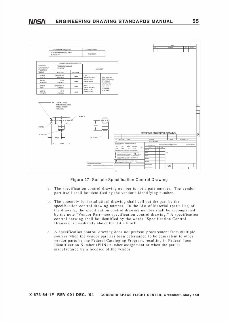
8/6/2019 Engineering Drawing Standards Manual GSFC-X-673!64!1F
http://slidepdf.com/reader/full/engineering-drawing-standards-manual-gsfc-x-673641f 67/128
X-673-64-1F REV 001 DEC. ‘94 GODDARD SPACE FLIGHT CENTER, Greenbelt , Mary land
ENGINEERING DRAWING STANDARDS MANUAL 55
REV
R E V
DATE APPROVAL
F O L D
L I N E
G C
GREENBELT,MARYLAND
SH
DESCRIPTION
REVISION
MATERIAL
Goddard Space Flight Center
WTSCALE
DRAWINGINTERPRETEDPERGSFC-X673 -64-1
MATERIALSPEC& NO.PARTNO.
HARDNESSTESTNOT REQUIRED
REMOVEALLBURRSAND SHARPEDGESR. 010ORCHAMFERMAX.
UNLESSOTHERWISESPECIFIED-DI MENSIONSAREIN INCHES
TESTHARDNESSPER ASTME-18, LOCATIONOPTIONAL
TESTHARDNESSPERASTME-18 WHEREINDICATED
ONFIELD OFDRAWINGTHUS
NONON-DESTRUCTIVEEXAMINATION(NDE) REQ'D
NDEREQUIREDPER S-313-009 CODETHISDRAWINGWAS PRODUCEDUSING
SOFTWARE:
FILE NAME:
VERSION:
TOLERANCES:
FLIGHTHARDWARE/POSTFABHARDNESSTEST REQ'D
F O L D
L I N E
.XX
ITEM
NO.
NEXTASSY
.XXX
REQDREQD
NAME
LISTOF MATERIAL
NATIONALAERONAUTICSAND
SPACEADMINISTRATION
DESCRIPTION
APPROVED-STRESS
APPROVED-ENGINEER
NONFLIGHT
USEDON
FRACTIONS
±1/16
APPROVED
DESIGNER
DRAWN
CHECKED
APPROVED
125DATEINIT
CODE
TITLE
SYM
GC
±.02 ±.005 ±1°
1.250
ø2X .020
.438-20 UNF-3B
FOR.25ODTUBING
PERAND10050
3 PLACES
PORT 1
PORT 3
PORT 2
1.190
2.380
WITHPORT3
PLUGGEDAPPLY
PRESSUREAS
FOLLOWS
PERMISSIBLELEAKAGE
ATRATEOF
INTERNAL EXTERNAL
5 PSI AT
PORT2
2250PSI
ATPORT2
5 PSI AT
PORT1
2250PSI
ATPORT1
1 DROPPERHR
ATPORT1
NONE
ATPORT1
1DROPPERHR
ATPORT1
NONE
ATPOR2
NONE
NONE
NONE
NONE
THESETESTS
DOWNDURING
SHOULDBE HELD
PORT1
PORT2
SHOULDBE HELD
DOWNDURING
THESETESTS
COMMENTS
PRODUCTIONTESTPROCEDURE
BESURETHAT
SEALINGPOPPET
ISLOOSEIN
VALVEWHEN
ISAPPLIED
PRESSURE
EACHTEST
VENDORNAME&ADDRESS
BUFFALO. N.Y.
SMITHENGINEERINGCOMPANYXA3-X29XX
VENDORPARTNO.
SPECIFICATION CONTROL DRAWING
3X
Figure 27: Sample Speci f icat ion Cont ro l Drawing
a. The specif icat ion control drawing number is not a par t number . The vendor
part i t sel f shal l be ident i f ied by the vendor 's ident i fying number.
b. The assembly (or instal lat ion) drawing shal l cal l out the par t by the
specif icat ion control drawing number. In the List of Mater ial (par ts l is t ) of
the drawing, the specif icat ion control drawing number shal l be accompanied
by the note “Vendor Par t—see specif icat ion control drawing.” A specif icat ion
control drawing shal l be ident i f ied by the words “Specif icat ion Control
Drawing” immediately above the Ti t le block.
c. A specif icat ion control drawing does not prevent procurement f rom mult iple
sources when the vendor par t has been determined to be equivalent to other
vendor par ts by the Federal Cataloging Program, resul t ing in Federal I tem
Ident i f icat ion Number (FIIN) number assignment or when the par t is
manufactured by a l icensee of the vendor .

8/6/2019 Engineering Drawing Standards Manual GSFC-X-673!64!1F
http://slidepdf.com/reader/full/engineering-drawing-standards-manual-gsfc-x-673641f 68/128
X-673-64-1F REV 001 DEC. ‘94 GODDARD SPACE FLIGHT CENTER, Greenbelt , Mary land
56 ENGINEERING DRAWING STANDARDS MANUAL
d. The preparat ion of specif icat ion control drawings can be avoided by procuring
the vendor 's manufactur ing drawings. In the event the vendor claims
proprietary r ights and refuses to provide his manufactur ing drawings, he shal l
be requested to furnish an out l ine drawing of his par t suff icient to include therequirements s tated above. When the vendor provides ei ther type of drawings
( i .e . , manufactur ing drawings or an out l ine drawing) , the par t number cal lout
on the drawing shal l be by the vendor 's number .
e . A specif icat ion control drawing shal l not upgrade a vendor 's par t beyond the
vendor 's s t ipulat ions.
4.15. Standard Part Drawing
Standard par ts shal l be selected from government and industry s tandards in that
order of precedence. I f nei ther of these contain a par t sat isfactory for the design
needs, a drawing shal l be prepared. Before preparat ion, i t must be determined
that the par t shal l be a GSFC standard par t , in which case i t shal l be draf ted onGSFC standard manual format .
4.16. Tabulated Drawing
A tabulated drawing depicts s imilar i tems with differences in character is t ics such
as dimensions, mater ial , f inish, and other requirements . These differences are
tabulated on the drawing, the f ixed character is t ics depicted once.
Pictor ial di fferences that are not clear should be shown in views or detai ls and
should be properly labeled. A tabulated drawing precludes the preparat ion of an
individual drawing for each i tem. See Figure 28.
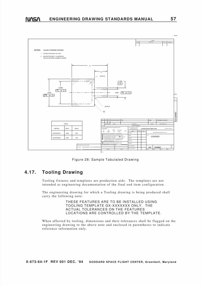
8/6/2019 Engineering Drawing Standards Manual GSFC-X-673!64!1F
http://slidepdf.com/reader/full/engineering-drawing-standards-manual-gsfc-x-673641f 69/128
X-673-64-1F REV 001 DEC. ‘94 GODDARD SPACE FLIGHT CENTER, Greenbelt , Mary land
ENGINEERING DRAWING STANDARDS MANUAL 57
B
A
1.375
1.250
DIM. B
3.625
3.500
DIM. A
GCXXXXXX5-3
GCXXXXXX5-1
PARTNO.
.020 Aø.953
ø1.360
2X R.31
2X R.31
.003 A
A.020
ø3.265
ø3.95
PASSIVATEPERQQ-P-35, TYPEII
BAGPARTPERMIL-P-116, METHODIII,
ANDTAGWITHPART NUMBERGC1234567.
UNLESSOTHERWISESPECIFIED
1.
2.
NOTES:
TABLEI
BAR CRES ASTMA582 /303CONDA
A
REV
R E V
DATE APPROVAL
F O L D
L I N E
G C 1 2 3 4 5 6 7
GREENBELT,MARYLAND
SH
DESCRIPTION
REVISION
MATERIAL
Goddard Space Flight Center
WTSCALE
DRAWINGINTERPRETEDPERGSFC-X673 -64-1
MATERIALSPEC& NO.PARTNO.
HARDNESSTESTNOT REQUIRED
REMOVEALLBURRSAND SHARPEDGESR. 010ORCHAMFERMAX.
UNLESSOTHERWISESPECIFIED-DI MENSIONSAREIN INCHES
TESTHARDNESSPER ASTME-18, LOCATIONOPTIONAL
TESTHARDNESSPERASTME-18 WHEREINDICATED
ONFIELD OFDRAWINGTHUS
NONON-DESTRUCTIVEEXAMINATION(NDE) REQ'D
NDEREQUIREDPER S-313-009 CODETHISDRAWINGWAS PRODUCEDUSING
SOFTWARE:
FILE NAME:
VERSION:
TOLERANCES:
FLIGHTHARDWARE/POSTFABHARDNESSTEST REQ'D
F O L D
L I N E
.XX
ITEM
NO.
NEXTASSY
.XXX
REQDREQD
NAME
LISTOF MATERIAL
NATIONALAERONAUTICSAND
SPACEADMINISTRATION
DESCRIPTION
APPROVED-STRESS
APPROVED-ENGINEER
NONFLIGHT
USEDON
FRACTIONS
±1/16
APPROVED
DESIGNER
DRAWN
CHECKED
APPROVED
125DATEINIT
CODE
TITLE
SYM
GC
±.02 ±.005 ±1°
1234567
COUPLER
Figure 28: Sample Tabulated Drawing
4.17. Tooling Drawing
Tooling f ixtures and templates are product ion aids . The templates are not
intended as engineer ing documentat ion of the f inal end i tem configurat ion.
The engineer ing drawing for which a Tool ing drawing is being produced shal l
carry the fol lowing note:
THESE FEATURES ARE TO BE INSTALLED USINGTOOLING TEMPLATE GX-XXXXXXX ONLY. THEACTUAL TOLERANCES ON THE FEATURESLOCATIONS ARE CONTROLLED BY THE TEMPLATE.
When affected by tool ing, dimensions and their tolerances shal l be f lagged on the
engineer ing drawing to the above note and enclosed in parentheses to indicate
reference information only.

8/6/2019 Engineering Drawing Standards Manual GSFC-X-673!64!1F
http://slidepdf.com/reader/full/engineering-drawing-standards-manual-gsfc-x-673641f 70/128
X-673-64-1F REV 001 DEC. ‘94 GODDARD SPACE FLIGHT CENTER, Greenbelt , Mary land
58 ENGINEERING DRAWING STANDARDS MANUAL
The fol lowing note shal l be added to the tool ing drawing:
THIS TOOLING IS USED TO FABRICATE PIECE PARTGX-XXXXXXX.
The tool ing drawing shal l be dimensioned the same way as the engineer ing
drawing.
4.18. Composite Material Drawing
A composi te mater ial drawing is an engineer ing representat ion of two or more
mater ials in combinat ion (reinforcing f ibers and resin binder) . The f iber and
resin differ in form or composi t ion, and are tai lored to meet specif ic engineer ing
propert ies . The drawing shal l specify the mult i -ply laminate configurat ion that
def ines the number of pl ies , the s tacking sequence, the ply angle or ientat ion, the
prepreg f iber-resin mater ials , and the physical dimensions.
For the fol lowing requirements , refer to Figure 29 as an example of a composi te
mater ial drawing.
a. A coordinate reference and angle direct ion shal l be shown for both the par t
and the s tacked detai l .
b. Each ply shal l be ident i f ied by I tem No., angle, and thickness , as shown in
Table 1 of Figure 29.
c. Dash numbers may be used to show variat ions, such as length and mater ial , as
shown in Table 2 of Figure 29.
d. Stacking sequence code (+30/0/-30/90) 2 S , as shown in Table 1 in Figure 29defines the fol lowing features:
Ply 1 +30-degree or ientat ion
Ply 2 0-degree or ientat ion
Ply 3 -30-degree or ientat ion
Ply 4 +90-degree or ientat ion
Subscr ipt “2 ” indicates repeat sequence (pl ies 1–4) two
t imes, for bui ld up of pl ies 5–8.
Subscr ipt “S” indicates symmetry, i .e . , pl ies 1–8 repeated in
reverse order for bui ldup of pl ies 9–16.
The code is read (+30/0/-30/90/+30/0/-30/90/90/-30/0/+30/90/-30/0/+30) .
Examples of other var iat ions to the code are (0 3 /902 /45/-45 3)S . This code is read
(0/0/0/90/90/+45/-45/-45/-45/-45/-45/-45/+45/90/90/0/0/0) .
In the same example, the subscr ipt “T” can be used in l ieu of “S” to designate the
total laminate. For example, (03 /90 2 /45/-45 6 /45/90 2 /0 3) T . However , in this
example, using the “S” to denote symmetry is the preferred method. “T” is
general ly reserved for laminates where symmetry is not specif ied, as in
(0/30/60/90) T .

8/6/2019 Engineering Drawing Standards Manual GSFC-X-673!64!1F
http://slidepdf.com/reader/full/engineering-drawing-standards-manual-gsfc-x-673641f 71/128
X-673-64-1F REV 001 DEC. ‘94 GODDARD SPACE FLIGHT CENTER, Greenbelt , Mary land
ENGINEERING DRAWING STANDARDS MANUAL 59
Figure 29: Composi te Mater ia l Drawing Example

8/6/2019 Engineering Drawing Standards Manual GSFC-X-673!64!1F
http://slidepdf.com/reader/full/engineering-drawing-standards-manual-gsfc-x-673641f 72/128
X-673-64-1F REV 001 DEC. ‘94 GODDARD SPACE FLIGHT CENTER, Greenbelt , Mary land
60 ENGINEERING DRAWING STANDARDS MANUAL
5. NUMBERING SYSTEM FOR DRAWINGS AND
SUPPORTING DOCUMENTATIONThe GSFC numbering system for ident i fying engineer ing drawings and associated
l is ts is based on the “uni t number” pr inciple, whereby the same basic number
assigned to an assembly drawing is also appl ied to index, usage, data, and par ts
l is ts .
a . Drawing numbers shal l consis t of assigned basic seven-digi t numbers ,
pref ixed by the let ter “G” (s ignifying GSFC) and a second let ter s ignifying the
drawing s ize (B, C, D, E, F , or J ) .
b. Associated l is t numbers shal l be the basic seven-digi t drawing number pref ix
with PL or IL as appl icable. Refer to Defini t ions paragraph 8.1 on page 71.
c. Al l GSFC organizat ions using drawing numbers shal l make their request to the
Mechanical Systems Divis ion, Mechanical Engineer ing Branch (designated
custodian) for blocks of numbers for their f l ight hardware and ground support
equipment .
d. The management of drawing numbers becomes the responsibi l i ty of the
engineer ing design group to whom they are assigned. Reassignment of the
numbers to group subsect ions or individuals , other contractors or
subcontractors , or other programs or projects must be control led, recorded,
and maintained by the Configurat ion Management Off icer .
e . Engineer ing documentat ion (drawings, engineer ing change orders , and
configurat ion change requests) shal l be retained by the Configurat ion Managerin the responsible engineer ing organizat ion unt i l otherwise directed by the
Project .
f . When i t i s necessary to ident i fy a drawing as a sketch, the number shal l be
assigned by the or iginator . The sketch shal l be maintained by the or iginator
to prevent the necessi ty of a central control . Sketches shal l not be prepared in
place of engineer ing drawings for procurement of mockups, models ,
preproduct ion hardware or f l ight hardware, and associated equipment .
g. GSFC numbers for specif icat ions, processes , and s tandards shal l be issued by
the specif ic organizat ion for which such documents are being developed.
Procedures governing the preparat ion of GSFC specif icat ions, processes , and
standards shal l be in accordance with GSFC-S-250-3, Guide for thePreparat ion of Speci f icat ions . The Library Services Branch of the GSFC
Information Management Divis ion shal l receive two copies of f inal , approved
documents that are of general interest and use. A l is t of exis t ing
specif icat ions is maintained by the Library Services Branch.

8/6/2019 Engineering Drawing Standards Manual GSFC-X-673!64!1F
http://slidepdf.com/reader/full/engineering-drawing-standards-manual-gsfc-x-673641f 73/128
X-673-64-1F REV 001 DEC. ‘94 GODDARD SPACE FLIGHT CENTER, Greenbelt , Mary land
ENGINEERING DRAWING STANDARDS MANUAL 61
h. In the absence of a project-directed document numbering plan, the fol lowing
system shal l be used:
revision letterordinal specification number issued in given year
year of specification issueBranch, Division or organization
issuing & maintaining specification
"S" for specification, "P" for procedure
Goddard Space Flight Center
GSFC - S - 722 - 93 - 002 - A
5.1. Part Numbering
Each detai l par t , subassembly, etc . , shal l be ident i f ied by a par t number as
fol lows:
a. An i tem covered by an approved s tandard and used without al terat ion or
select ion shal l be ident i f ied by the proper s tandard number (such as MS
number for mil i tary s tandard) , which shal l include any dash number or code
necessary for complete ident i ty.
b. Each nonstandard i tem shal l be ident i f ied by a par t number that shal l be, or
shal l include, the drawing number.
c . Vendor-design ed and manufactured par ts or assemblies shal l be ident i f ied by
the vendor 's par t number . See “Specif icat ion Control Drawing,” paragraph
4.14 on page 54 , and “Source Cont ro l Drawing,” paragraph 4 .13 on page 53 .
d. Al tered or selected par ts shal l be ident i f ied as required. See “Altered or
Selected Vendor Par t Drawing,” paragraph 4.1 on page 39.
e. Symmetr ical ly opposi te par ts shal l be designated by -1 (shown) and -2
(opposi te) carrying the odd/even relat ionship to higher numbers as necessary.
The par t shown shal l a lways be an odd number, and i ts opposi te , the next
higher number .
Par ts shal l be ident i f ied on the f ield of drawing by showing both the ident i fying
part number and f ind number where cross-referenced on a separate Engineer ing
Parts List . See “Sample Assembly Drawing,” Figure 17 on page 40. When the
parts appear in the List of Mater ial on the drawing, only the i tem number is cal led
out on the f ield of the drawing. See Figure 34, “Sample Assembly Drawing With
List of Mater ial ,” on page 80.
A detai l drawing depicts a s ingle detai l par t , and the par t shal l be designated by
the drawing number. See “Detai l Drawing,” paragraph 4.3 on page 41.
An inseparable assembly drawing depicts par ts permanent ly fastened together , and
the assembly shal l be designated by the drawing number. The individual par ts
shal l be designated by par t number as descr ibed per “Inseparable Assembly
Drawing,” paragraph 4 .6 on page 44 .

8/6/2019 Engineering Drawing Standards Manual GSFC-X-673!64!1F
http://slidepdf.com/reader/full/engineering-drawing-standards-manual-gsfc-x-673641f 74/128
X-673-64-1F REV 001 DEC. ‘94 GODDARD SPACE FLIGHT CENTER, Greenbelt , Mary land
62 ENGINEERING DRAWING STANDARDS MANUAL
Each of the par ts shown on a tabulated drawing shal l be ident i f ied by the drawing
number suff ixed with a dash number . The basic drawing number alone shal l not
be used to ident i fy a par t . See “Tabulated Drawing,” paragraph 4.16 on page 56.
Parts that must be mated, and for which replacement as a matched set or pair is
required, shal l be assigned a s ingle number to designate each matched set or pair .
Component par ts shown in matched-set drawings instead of separate detai l
drawings shal l be ident i f ied by the ident i fying par t number and f ind number . See
“Matched-Set Drawing,” paragraph 4.9 on page 48.
5.2. Find or Item Numbering
Under the f ind or i tem numbering system, a number is assigned to a par t or detai l
assembly for the purpose of locat ing i t in the f ield of the assembly drawing. The
find or i tem number is also shown in the Engineer ing Parts List for an assembly
drawing, cross-referenced to the par t number used for procurement purposes.
5.3. Order of Precedence of Specifications and Standards
When ident ical par ts or assemblies of equal qual i ty are ident i f ied by more than
one document , the i tem shal l be referenced on drawings in the fol lowing order :
5.3.1. Group I
Group I covers government specif icat ions and s tandards l is ted for
use by GSFC and industry documents coordinated to the extent
indicated as fol lows in (c) and (e) .
a . Coordinated federal specif icat ions and s tandards.
b. Coordinated mil i tary specif icat ions and s tandards ( including
JANs, ANs, and ANDs) .
c . Industry specif icat ions and s tandards (e .g. , those promulgated
by nat ional ly recognized associat ions, commit tees , and
technical societ ies) having coordinated s tatus establ ished under
pol icies and procedures of other government agencies and
approved for GSFC use.
d. Limited coordinat ion mil i tary and inter im federal specif icat ions
and s tandards issued by other government agencies and
approved for GSFC use.
e . Industry specif icat ions and s tandards having l imited
coordinat ion s tatus establ ished under pol icies and procedures of
other government agencies and approved for GSFC use.
5.3.2. Group II
Group II covers industry specif icat ions and s tandards (e .g. , those
promulgated by nat ional ly recognized associat ions, commit tees , and
technical societ ies) approved for use by GSFC, for which s tatus
equivalent to mil i tary documents has not been establ ished.

8/6/2019 Engineering Drawing Standards Manual GSFC-X-673!64!1F
http://slidepdf.com/reader/full/engineering-drawing-standards-manual-gsfc-x-673641f 75/128
X-673-64-1F REV 001 DEC. ‘94 GODDARD SPACE FLIGHT CENTER, Greenbelt , Mary land
ENGINEERING DRAWING STANDARDS MANUAL 63
5.3.3. Group III
Group III covers Government specif icat ions and s tandards not
previously l is ted by GSFC.
5.3.4. Group IV
Group IV covers industry specif icat ions and s tandards not
previously l is ted for use by GSFC. Company specif icat ions and
standards are not to be considered as a par t of this group. Copies
of industry specif icat ions and s tandards should be obtained from
the associat ion concerned.
5.3.5. Group V
Group V covers company specif icat ions and s tandards. Reference
to a company specif icat ion or s tandard for new appl icat ions or
designs shal l be discont inued upon the issuance of a specif icat ion
or s tandard in Group I , I I , I I I , or IV covering an interchangeable
i tem of equivalent qual i ty.
Note (appl icable to Groups I , I I , IV, and V above):
When industry specif icat ions and s tandards are specif ied on GSFC
drawings and documents , such specif icat ions and s tandards shal l be
avai lable to GSFC personnel .
8/6/2019 Engineering Drawing Standards Manual GSFC-X-673!64!1F
http://slidepdf.com/reader/full/engineering-drawing-standards-manual-gsfc-x-673641f 76/128
X-673-64-1F REV 001 DEC. ‘94 GODDARD SPACE FLIGHT CENTER, Greenbelt , Mary land
64 ENGINEERING DRAWING STANDARDS MANUAL
6. ENGINEERING ORDER
6.1. General Requirements
The use of Engineer ing Order (EO) for the purpose of revis ing released drawings
is the preferred method of changing drawings, al though the method of direct
change to the drawing may be chosen by the project engineer .
After an EO system is elected, i t i s the responsibi l i ty of that project design
act ivi ty to assign numbering and maintain the documentat ion system. The
approved EO is considered an off icial par t of the or iginal drawing and shal l
always be avai lable to others , even af ter incorporat ion. With this system,
reference to EOs in the revis ion block of drawings is permit ted in place of the
usual detai led l is t ing of changes.
6.2. Format Sample
The fol lowing minimum information should be included on an EO form. See
Figure 30a on page 66.
1 . DRAWING & REV. LEVEL: The number of the drawing to be changed and the
revis ion level affected. Where the change is exact ly the same on more than
one drawing, add an aster isk to the drawing and revis ion level block; then add
the drawing numbers along with the next appl icable EO number to the aster isk
table on the f ield of change on EO page 1. I f more than one EO page is
required, the addi t ional EO pages wil l only note that those pages affect the
l is t of drawings the EO is wri t ten against .
2. INC. REV.: The revis ion let ter to be provided by the Configurat ion Manager
(CM) at the t ime of drawing change incorporat ion. Outstanding EO numbers
may be incorporated under one revis ion let ter .
3. TITLE: Ti t le of the drawing to be revised.
4. NEXT ASSEMBLY: Next assembly number of the drawings affected by the
change .
5. USED ON: The type of equipment such as Ground-Support Equipment (GSE)
or Fl ight (FLT).
6. PROGRAM: Name of program.
7. REASON: Reason why the change is necessary rather than descr ipt ion of the
change. A Configurat ion Change Request (CCR) number and class to be
provided by the project engineer where appl icable or when required by the
CM.
8. TYPE OF EO:
Advance Notice of Change : A change to the drawing that shal l take place at
some future date. Several EOs may be incorporated under the same revis ion
let ter .
8/6/2019 Engineering Drawing Standards Manual GSFC-X-673!64!1F
http://slidepdf.com/reader/full/engineering-drawing-standards-manual-gsfc-x-673641f 77/128

8/6/2019 Engineering Drawing Standards Manual GSFC-X-673!64!1F
http://slidepdf.com/reader/full/engineering-drawing-standards-manual-gsfc-x-673641f 78/128
X-673-64-1F REV 001 DEC. ‘94 GODDARD SPACE FLIGHT CENTER, Greenbelt , Mary land
66 ENGINEERING DRAWING STANDARDS MANUAL
EODRAWING& REVLEVEL
SHEET
ISSUEDBY CMO
GSFCCODELOCATION DATE
1. DRAWINGTITLE
5. TYPEOFEO:
ADVANCEDNOTICEOFCHANGE
Drawing will be revised
DEVIATION
Drawing will not
OTHER(Explain)
DATE
SERIAL
EFFECTIVE7.
8. DESCRIPTION
ENGINEERINGORDERGODDARDSPACEFLIGHTCENTER
GREENBELT,MARYLANDOF
be revised
CCBAPPROVAL3a .
JOBORDERNO..3b
4.
DISPOSITION R W K
AS
USE
IS S C R A P
N O
P A R T S
RAWMATERIAL
PARTIN PROCESS
6. PROGRAM
USEDON
NEXTASSY
10. DRAWNBY CHECKED: APPROVED: APPROVED: ENGINEERING:
DATE CODE CODEDATE CODEDATE CODEDATE CODEDATE
M A D E
REASON2.
INCREVEONO.
3 8 9 7 19 18 1 10 20 2
14
12
6
5
4
171611 13 15
Figure 30a: Engineer ing Order (sheet 1)
EOENGINEERINGORDER
GODDARDSPACEFLIGHTCENTER
GREENBELT,MARYLANDOF
DRAWING&REVLEVEL EONO. INCREV
SHEET
Figure 30b: Engineer ing Order (sheet 2)
8/6/2019 Engineering Drawing Standards Manual GSFC-X-673!64!1F
http://slidepdf.com/reader/full/engineering-drawing-standards-manual-gsfc-x-673641f 79/128
X-673-64-1F REV 001 DEC. ‘94 GODDARD SPACE FLIGHT CENTER, Greenbelt , Mary land
ENGINEERING DRAWING STANDARDS MANUAL 67

8/6/2019 Engineering Drawing Standards Manual GSFC-X-673!64!1F
http://slidepdf.com/reader/full/engineering-drawing-standards-manual-gsfc-x-673641f 80/128
X-673-64-1F REV 001 DEC. ‘94 GODDARD SPACE FLIGHT CENTER, Greenbelt , Mary land
68 ENGINEERING DRAWING STANDARDS MANUAL
7. DRAWING REVISIONS
7.1. Revision Methods
Revisions in the f ield of drawings are made by delet ion, ei ther by erasure or
crossing out (a ser ies of paral lel l ines placed on the face of drawing over the
deleted port ions of drawing) , by addi t ion, or by redrawing (al l del ineat ions shal l
be made to scale) .
7.2. Revision Identification
Revisions shal l be ident i f ied by symbols in the f ield of the drawing (see
paragraph 7.4) cross-referenced to the revis ion descr ipt ion. Revision symbols
shal l be entered in the revis ion block (see Figures 31a, 31b, and 31c, page 69) .
Revisions shal l be by alphabet ical le t ter and order , except that le t ters I , O, Q, S,X, and Z shal l not be used as revis ion symbols . Fol lowing let ter Y, use AA, AB,
etc.; af ter AY, use BA, BB, etc .
7.3. Revision of Multisheet Drawings
There is only one acceptable method of recording changes to mult isheet drawings.
Revisions to any sheet(s) shal l be recorded in the revis ion descr ipt ion block on
sheet 1, and reference shal l be made to sheet(s) affected. Level of revis ion shal l
be changed on each drawing sheet whether or not that par t icular sheet is affected.
The revis ion descr ipt ion block on al l sheets other than sheet 1 shal l s tate “See
sheet 1 for revis ions.”
7.4. Revision Recording
A symbol (e .g. , “A3” ) enclosed in a ci rcle shal l appear in the f ield of drawing at
the point of revis ion. The let ter “A” refers to any revis ions completed at a given
t ime. The number fol lowing refers to the number of the revis ion made.
Figure 31a shows examples of this . The same symbol may appear more than once
if , in the revis ion descr ipt ion column, more than one act ion took place per l ine
(see Figure 31a under symbol “A3,” l ine 2) .
When changes are made to a drawing through a direct incorporat ion, revis ion
symbols are required on the f ield of the drawing, and abbreviated descr ipt ions of
the changes must be recorded in the revis ion block.
When changes are made to a drawing through an EO or Revision Notice system,
revis ion symbols are not required on the f ield of the drawing, but the Revision
Block must s tate “See EO number for changes” or “See Revision Notice
number ” in the revis ion descr ipt ion column.
For ei ther method of incorporat ion, the person incorporat ing the revis ion, the
person assigned to check the incorporat ion, and the cognizant engineer
responsible for the revis ion al l shal l date and ini t ial the revis ion block in the
approved column.
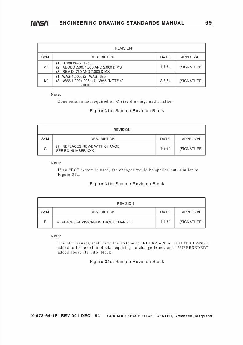
8/6/2019 Engineering Drawing Standards Manual GSFC-X-673!64!1F
http://slidepdf.com/reader/full/engineering-drawing-standards-manual-gsfc-x-673641f 81/128

8/6/2019 Engineering Drawing Standards Manual GSFC-X-673!64!1F
http://slidepdf.com/reader/full/engineering-drawing-standards-manual-gsfc-x-673641f 82/128
8/6/2019 Engineering Drawing Standards Manual GSFC-X-673!64!1F
http://slidepdf.com/reader/full/engineering-drawing-standards-manual-gsfc-x-673641f 83/128
X-673-64-1F REV 001 DEC. ‘94 GODDARD SPACE FLIGHT CENTER, Greenbelt , Mary land
ENGINEERING DRAWING STANDARDS MANUAL 71
8. PARTS LIST AND INDEX LIST
This sect ion establ ishes minimum requirements for the preparat ion andsubmission of Par ts Lis ts (PL) and Index Lists ( IL) used with engineer ing
drawings.
Parts Lis ts may be prepared for each assembly drawing in accordance with this
sect ion. For par ts l is ts on drawings, see Figure 34 on page 80 or Figure 3 on
page 10 .
Index Lists may be prepared for each Payload, Engineer ing Model , Major
Assembly, Complex Assembly of assemblies , as directed by Project Manager .
8.1. Definitions
Cover Sheet: This refers to the f i rs t sheet of each Parts List or Index List and is
a record of the revis ions.
Parts List (PL): This is a tabulat ion of the i tems necessary for fabr icat ing or
assembling the end i tem(s) to which the l is t appl ies .
Index List (IL): This is a l is t of the one pr incipal and al l subordinate PLs
appl icable to a major assembly.
Bulk Materials: These are i tems that are necessary const i tuents of an assembly or
subassembly, for which the quant i ty required is not readi ly predeterminable.
Examples are oi l , wax, solder , cement , ink, damping f luid, grease, powdered
graphi te , f lux, welding rod, thread, twine, and chain. I f the quant i ty is known,but the physical nature of the mater ial is such that i t i s not adaptable to depict ion
on a drawing, or the mater ial can be cut to f inished s ize by the use of such hand
or bench tools as shears , pl iers , knives, etc . wi thout fur ther machining operat ions,
then the mater ial 's configurat ion shal l be ful ly descr ibed in wri t ing without the
necessi ty of pictor ial presentat ion.
Special Handling Equipment and Packaging: This term appl ies to i tems such as
boxes, shipping containers , cradles , crane at tachments , and other special i tems
needed for s tor ing and t ransport ing.
Special Test Equipment: This term appl ies to i tems of special tes t equipment
that are required for government inspect ion or service maintenance, such as test
s tands, indicators , e tc .
Applicable Standards, Specif ications, and Publications: This term appl ies to
documents referenced on or invoked by the drawings.
8.2. Requirements
8.2.1. List Preparation
The PL and IL may be prepared manual ly or by typewri ter or
computer word processor .

8/6/2019 Engineering Drawing Standards Manual GSFC-X-673!64!1F
http://slidepdf.com/reader/full/engineering-drawing-standards-manual-gsfc-x-673641f 84/128
X-673-64-1F REV 001 DEC. ‘94 GODDARD SPACE FLIGHT CENTER, Greenbelt , Mary land
72 ENGINEERING DRAWING STANDARDS MANUAL
8.2.2. List Formats
Lists shal l use preprinted 8 1/2- by 11-inch s ize format . The
preparat ion requirements are provided herein.
When more than a s ingle sheet is required to prepare or revise a
l is t , the l is t t i t le is required on the f i rs t sheet only.
The design act ivi ty shal l use a cover sheet as i l lust rated in
Figure 32a on page 74. Entr ies on the cover sheet shal l be
completed as explained in “Cover Sheet ,” sect ion 8.3, below.
8.2.3. Revision Identification
A revision let ter and the date of revis ion shal l be appl ied to each
l is t when any change is made. The let ters I , O, Q, and X shal l not
be used as revis ion let ters . Lis t shal l be revised independent ly of the associated drawings.
8.2.4. Deleting Items
I tems to be deleted may be ei ther l ined out , erased, or omit ted.
8.2.5. Adding Items
New or superseding i tems may be added at the end of a l is t or
inser ted in the l is t in proper sequence.
8.3. Cover Sheet
The Cover Sheet shal l be the f i rs t sheet for each PL or IL and shal l
be prepared as indicated herein.
8.3.1. Format
The Cover Sheet shal l be prepared on Form 670-36 (1/65) . Refer to
Figure 32a on page 74.
8.3.2. Entries
Entr ies shal l be made in the blocks and columns of the Cover Sheetas directed on the fol lowing page:
1. CODE IDENT: Enter Code Ident i f icat ion number as assigned by
Federal Supply CAGE Publ icat ion H4/H8 for using act ivi ty.
Number is located in t i t le block of design act ivi ty.
2. LIST NO.: Enter the number of the PL or IL for which the cover
sheet is being prepared.
3. SHEET OF : Enter the total number of sheets used.
8/6/2019 Engineering Drawing Standards Manual GSFC-X-673!64!1F
http://slidepdf.com/reader/full/engineering-drawing-standards-manual-gsfc-x-673641f 85/128
X-673-64-1F REV 001 DEC. ‘94 GODDARD SPACE FLIGHT CENTER, Greenbelt , Mary land
ENGINEERING DRAWING STANDARDS MANUAL 73
4. REV: Enter revis ion let ter of the latest revis ion to the PL.
Changes to this block shal l be made by erasure.
5. ITEM NOMENCLATURE: Enter the same nomenclature thatappears in the Ti t le block of the assembly for which the l is t i s
being prepared. The i tem nomenclature shal l a lways be a noun.
6. VENDOR: If prepared by contractor for GSFC, enter contractor
name and Federal Supply CAGE Code Numbers .
7. PREPARED : Enter name of person preparing l is t .
8. APPROVED : Enter s ignature of person approving for accuracy
and completeness .
9. ENG APPROVAL: Enter s ignature of Assis tant Project Engineer
(opt ional) .
10. ENG APPROV AL: Enter s ignature of Project Eng ineer
(mandatory for al l procurement) .
11. AUTHENTI CATION: Enter name of person de signated to s ign
for design act ivi ty or divis ion.
12 . CONTRACT NO: When prepared by cont rac tor for GSFC, en ter
the contract number .
13. LTR: Enter revi s ion let ter of current rev is ion.
14. DESCRIPT ION: Enter a complete and concise descr ipt io n of the
revis ion that appl ies to the PL.
15. DATE: Enter da te of revis ion.
16. APP (Approval) : En ter ini t ials of person complet ing revis ion
review.
17. RECORD OF R EVISION: Enter revis io n s tatus of individual PL
sheets .

8/6/2019 Engineering Drawing Standards Manual GSFC-X-673!64!1F
http://slidepdf.com/reader/full/engineering-drawing-standards-manual-gsfc-x-673641f 86/128
X-673-64-1F REV 001 DEC. ‘94 GODDARD SPACE FLIGHT CENTER, Greenbelt , Mary land
74 ENGINEERING DRAWING STANDARDS MANUAL
Figure 32a: Parts List (and Index List) Cover Sheet
8/6/2019 Engineering Drawing Standards Manual GSFC-X-673!64!1F
http://slidepdf.com/reader/full/engineering-drawing-standards-manual-gsfc-x-673641f 87/128
X-673-64-1F REV 001 DEC. ‘94 GODDARD SPACE FLIGHT CENTER, Greenbelt , Mary land
ENGINEERING DRAWING STANDARDS MANUAL 75
8.4. Parts List Continuation Sheet
The PL cont inuat ion sheet shal l be prepared as indicated herein. Circled numbers
have been assigned to each column or block for ident i f icat ion only. The PL shal lcontain a cover sheet and as many PL cont inuat ion sheets as necessary to
completely l is t a l l the information.
8.4.1. Format
The PL cont inuat ion sheet shal l be prepared on Form 670-37 (1/65) .
Refer to Figure 32b on page 76
8.4.2. Entries
Entr ies shal l be made in the blocks and columns as directed below:
1. PARTS LIST NO.: On each sheet of the PL, enter the number of
the corresponding drawing.
2. SHEET NO.: On each sheet , enter the appropriate sheet number .
3. ITEM FIND NOS.: Enter number taken from assembly drawing.
4 . DWG. DOCUMENT PART OR STOCK NO.: Enter the par t
number or other ident i fying number of each i tem in the l is t .
5 . QTY REQD PER ASSY.: Enter the quanti ty requi red for each
assembly.
6. CODE IDENT NO. (Code ident i f icat ion number) : Enter
appropriate number assigned to the design act ivi ty per CAGE
Publicat ion H4/H8. When a government or industry s tandard
part or specif icat ion number appears in Column 4, no entry
shal l be made in Column 6. When the Code Ident i f icat ion
Number for an i tem is ident ical to that entered in Block 1 of the
Cover Sheet , do not repeat the number in Column 6 of the PL
cont inuat ion sheet .
7. DRAWING TITLE OR ITEM DESCRIPT ION (I tem descr ipt ion
or nomenclature) : Enter the noun or noun phrase descr ibing the
i tem whose par t or ident i fying number appears on assembly
drawing.
8. REMARKS: Enter information that could be useful for reference
[i .e . , specif icat ion, control drawings, designat ions (e .g. , R10,
J14, etc .) , vendor 's i tems, etc .] .
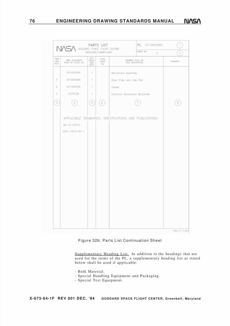
8/6/2019 Engineering Drawing Standards Manual GSFC-X-673!64!1F
http://slidepdf.com/reader/full/engineering-drawing-standards-manual-gsfc-x-673641f 88/128
8/6/2019 Engineering Drawing Standards Manual GSFC-X-673!64!1F
http://slidepdf.com/reader/full/engineering-drawing-standards-manual-gsfc-x-673641f 89/128
X-673-64-1F REV 001 DEC. ‘94 GODDARD SPACE FLIGHT CENTER, Greenbelt , Mary land
ENGINEERING DRAWING STANDARDS MANUAL 77
- Appl icable Standards, Specif icat ions, and Publ icat ions.
8.5. Index List Continuation Sheet
The IL cont inuat ion sheet shal l be prepared as indicated herein. Circled numbers
have been assigned to each column or block for ident i f icat ion only. The IL shal l
contain a cover sheet and as many IL cont inuat ion sheets as necessary to
completely l is t a l l the information.
8.5.1. Format
The IL cont inuat ion sheet shal l be prepared on Form 670-39 (1/65) .
Refer to Figure 33 on page 78.
8.5.2. Entries
Entr ies shal l be made in the blocks and columns as directed below:
1. INDEX LIST NUMBER: On each sheet , enter the number of
f i rs t assembly level ( top or main assembly) .
2. SHEET NO.: On each sheet , enter the appropriate sheet number .
3. CODE IDENT.: Enter code ident i f icat ion taken from PL.
4. LIST NO.: Enter number of the PL.
5. LIST NOMENCLATURE: Enter nomenclature as i t appears on
the PL.
6. ASSY LEVEL: Enter the next assembly level number of the l is t
number .
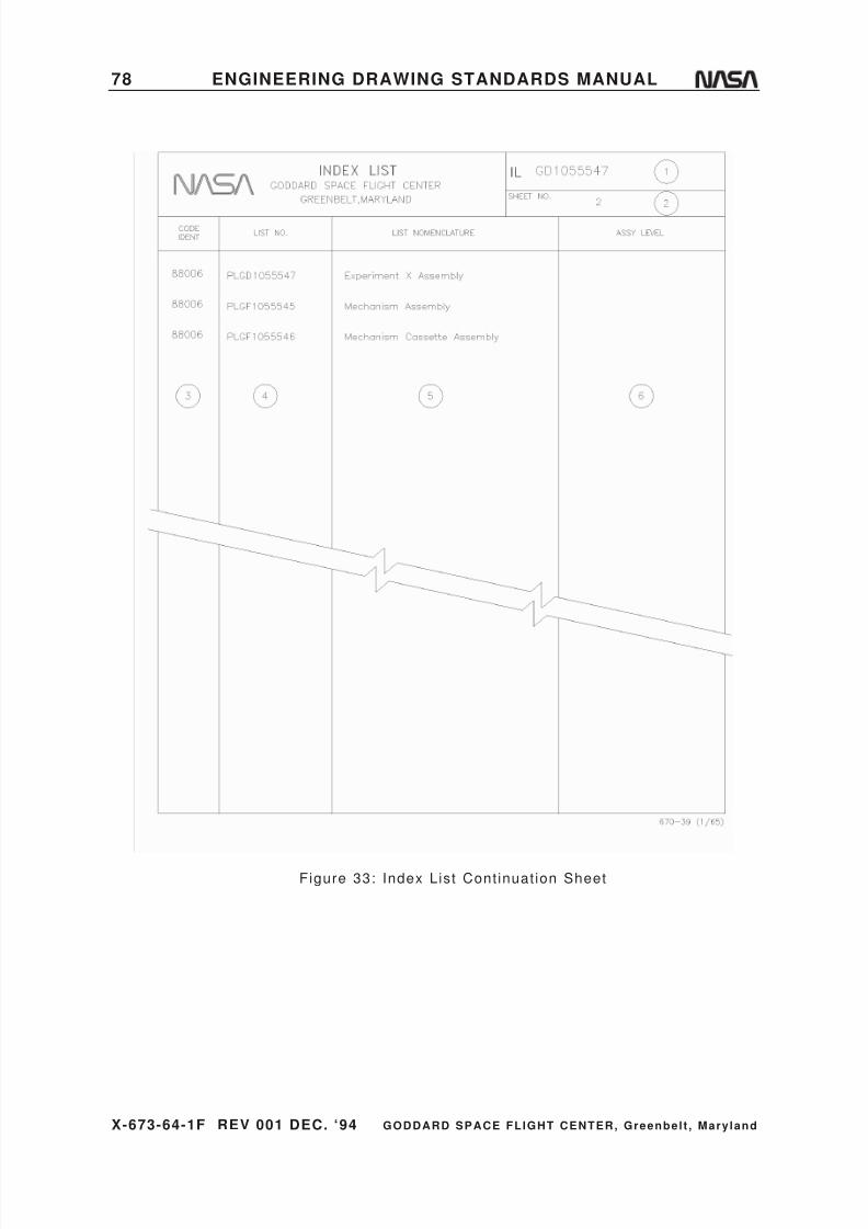
8/6/2019 Engineering Drawing Standards Manual GSFC-X-673!64!1F
http://slidepdf.com/reader/full/engineering-drawing-standards-manual-gsfc-x-673641f 90/128
X-673-64-1F REV 001 DEC. ‘94 GODDARD SPACE FLIGHT CENTER, Greenbelt , Mary land
78 ENGINEERING DRAWING STANDARDS MANUAL
Figure 33: Index List Cont inuat ion Sheet
8/6/2019 Engineering Drawing Standards Manual GSFC-X-673!64!1F
http://slidepdf.com/reader/full/engineering-drawing-standards-manual-gsfc-x-673641f 91/128
X-673-64-1F REV 001 DEC. ‘94 GODDARD SPACE FLIGHT CENTER, Greenbelt , Mary land
ENGINEERING DRAWING STANDARDS MANUAL 79
8.6. Find or Item Number System of Identification
8.6.1. Definition
A find number or i tem number is a number assigned to a par t or
subassembly for the purpose of locat ing the par t or subassembly in
the f ield of the assembly drawing. The f ind or i tem number is also
shown in the Par ts Lis t for an assembly drawing, whether the l is t i s
separate or an integral par t of the drawing. The “f ind number” is
usual ly associated with a separate Par ts Lis t , and the “i tem number”
is usual ly associated with the List of Mater ial on drawings, but
both are used for locat ing par ts . Par ts and subassemblies are
ident i f ied by other numbers for purposes of procurement and
marking. These ident i fying numbers are cross-referenced to the
f ind or i tem numbers in the PL or in a tabulat ion on the assembly
drawing.
8.6.2. Application and Limitation
The f ind or i tem number system provides a quick means of locat ing
parts on a relat ively smal l area of a drawing having a high densi ty
of par ts . I t i s preferred that the convent ional method of
ident i f icat ion ( i tem numbers) be used on drawings of s imple
assemblies , even though f ind and par t numbers are used for
complex assemblies that are components of the same equipment .
See Figure 34 on page 80. For a sample drawing of an assembly
using the f ind and par t number system, see Figure 17 on page 40.
The i tem number system of ident i f icat ion shal l a lso be used to
locate pieces on drawings of inseparable assemblies when mater ialspecif icat ions or mater ial tempers differ f rom one another .
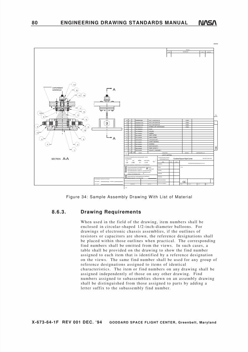
8/6/2019 Engineering Drawing Standards Manual GSFC-X-673!64!1F
http://slidepdf.com/reader/full/engineering-drawing-standards-manual-gsfc-x-673641f 92/128
X-673-64-1F REV 001 DEC. ‘94 GODDARD SPACE FLIGHT CENTER, Greenbelt , Mary land
80 ENGINEERING DRAWING STANDARDS MANUAL
EXPERIMENT
8
11
7
6
3
5
4
13
3
2
1
14
10
9
4
13
3
2
GD1416697 MOUNTC, ASSEMBLY
1 1 GD1416678 BASE, MOUNTC
2 2 GC1416680 SEAT, MOUNTC
3 3 GC1416640 BEARING
4 2 GC1416681 SHAFT, BEARING
5 1 GD1416679 STEM, MOUNTC
6 1 GC1416638 SEAT, LOWER
7 1 GC1416637 SEAT, UPPER
8 1 GC1416636 SLEEVE
9 1 SPACER
10 1 SHIM
11 2
NUT, 3/4-16UNF-3B
CRES
12 1 NUT, 5/8-18UNF-3B CRES13 4
SCREW, CAP, HEXAGONHD
CRES
14 4 NUT, 1/4-2BUNF-3B CRES
GC1416635-1
MS20500-428
MS35308-314
MS20500-1018MS20500-1214
GC1416639-1
X
A
A
12
INTERFACE
A-ASECTION
REV
R E V
DATE APPROVAL
F O L D
L I N E
G C
GREENBELT,MARYLAND
SH
DESCRIPTION
REVISION
MATERIAL
Goddard Space Flight Center
WTSCALE
DRAWINGINTERPRETEDPERGSFC-X673-64- 1
MATERIALSPEC& NO.PARTNO.
HARDNESSTESTNOT REQUIRED
REMOVEALLBURRSAND SHARPEDGESR. 010ORCHAMFERMAX.
UNLESSOTHERWISESPECIFIED-DI MENSIONSAREIN INCHES
TESTHARDNESSPER ASTME-18, LOCATIONOPTIONAL
TESTHARDNESSPER ASTME-18 WHEREINDICATED
ONFIELD OFDRAWINGTHUS
NONON-DESTRUCTIVEEXAMINATION(NDE)REQ'D
NDEREQUIREDPER S-313-009 CODETHISDRAWING WASPRODUCEDUSING
SOFTWARE:
FILENAME:
VERSION:
TOLERANCES:
FLIGHTHARDWARE/POSTFABHARDNESSTESTREQ'D
F O L D
L I N E
.XX
ITEM
NO.
NEXTASSY
.XXX
REQDREQD
NAME
LISTOF MATERIAL
NATIONALAERONAUTICSAND
SPACEADMINISTRATION
DESCRIPTION
APPROVED-STRESS
APPROVED-ENGINEER
NONFLIGHT
USEDON
FRACTIONS
±1/16
APPROVED
DESIGNER
DRAWN
CHECKED
APPROVED
125DATEINIT
CODE
TITLE
SYM
GC
±.02 ±.005 ±1°
Figure 34: Sample Assembly Drawing With List of Mater ial
8.6.3. Drawing Requirements
When used in the f ield of the drawing, i tem numbers shal l be
enclosed in ci rcular-shaped 1/2- inch-diameter bal loons. For
drawings of electronic chassis assemblies , i f the out l ines of
resis tors or capaci tors are shown, the reference designat ions shal l
be placed within those out l ines when pract ical . The corresponding
find numbers shal l be omit ted from the views. In such cases, atable shal l be provided on the drawing to show the f ind number
assigned to each i tem that is ident i f ied by a reference designat ion
on the views. The same f ind number shal l be used for any group of
reference designat ions assigned to i tems of ident ical
character is t ics . The i tem or f ind numbers on any drawing shal l be
assigned independent ly of those on any other drawing. Find
numbers assigned to subassemblies shown on an assembly drawing
shal l be dis t inguished from those assigned to par ts by adding a
let ter suff ix to the subassembly f ind number .
8/6/2019 Engineering Drawing Standards Manual GSFC-X-673!64!1F
http://slidepdf.com/reader/full/engineering-drawing-standards-manual-gsfc-x-673641f 93/128
X-673-64-1F REV 001 DEC. ‘94 GODDARD SPACE FLIGHT CENTER, Greenbelt , Mary land
ENGINEERING DRAWING STANDARDS MANUAL 81
8.7. List of Material
A List of Mater ial (LM) shal l be prepared and included on each assembly drawing
to provide the individual par t or subassembly i tem number, quant i ty required, par tnumber , descr ipt ion, mater ial , and mater ial specif icat ion. See Figure 34 on
page 80 .
8.7.1. Format
The List of Mater ial shal l be placed above the drawing Ti t le block
as shown in Figure 34 on page 80 .
8.7.2. Entries
Entr ies shal l be made in the blocks and columns as indicated in
Figure 3 on page 10.

8/6/2019 Engineering Drawing Standards Manual GSFC-X-673!64!1F
http://slidepdf.com/reader/full/engineering-drawing-standards-manual-gsfc-x-673641f 94/128
X-673-64-1F REV 001 DEC. ‘94 GODDARD SPACE FLIGHT CENTER, Greenbelt , Mary land
82 ENGINEERING DRAWING STANDARDS MANUAL
9. DOCUMENTATION MANAGEMENT
9.1. Typical Drawing Flow for Flight Projects
Engineer(acceptance or rejection)
Engineer(concept)
Designer Documents(detail, subassy., assy., instl., etc.)
on CAD or conventional board drawing
Designer
(layout)
Engineer (approvalof layout concepts)
Engineer
(review)
Design Analyst
(checking/review)
Designer(modifications)
Design Analyst(checking approval of
CAD/paper or vellum original)
Engineer(approval)
Configuration Manager
1. Update Master CAD File with Names & Dates2. Release Prints to Fabrication
Changes to
Released Drawings
Engineer
(considerationof suggestions
affecting design)
PartsCompleted
PartsGSFC QA
No Yes Engineer EOs(change notice)
Advance
Shop Copy(optional)
Designer(records change &
forwards check copy)
Figure 35: Typica l Drawing Flow for F l ight Pro jects

8/6/2019 Engineering Drawing Standards Manual GSFC-X-673!64!1F
http://slidepdf.com/reader/full/engineering-drawing-standards-manual-gsfc-x-673641f 95/128
X-673-64-1F REV 001 DEC. ‘94 GODDARD SPACE FLIGHT CENTER, Greenbelt , Mary land
ENGINEERING DRAWING STANDARDS MANUAL 83
9.2. Archiving
Drawings, Engineer ing Orders (EOs) , Cert i f icat ion Logs, Associated Lists , and
Engineer ing Parts Lists (EPLs) shal l be archived af ter s ignoff . Fol lowing aresome sample archiving methods:
a. Fi l ing of al l paper or iginals .
b. Scanning of the paper or iginals to a s tandard digi tal raster image format such
as CCITT Group 4 (CALS, MIL-R-28002) and then using a digi tal s torage
system to archive the resul t ing database of raster images.
c . Microf i lming and s tor ing on aperture cards when requested by a GSFC
divis ion that s t i l l has equipment to ret r ieve the information.
Note :
Before deciding to archive using aperture cards, the avai labi l i ty of ret r ieval
equipment and the qual i ty of reproduct ion should be considered. The qual i ty
of drawings, l i s ts , and documents shal l meet the legibi l i ty and contrast
requirements of MIL-D-5480 and MIL-M-9868. The microf i lm suppl ied shal l
be Type I , Class 1 .
9.3. Computer-Aided Design Drawings
The purpose of this sect ion is to set pol icy on how Computer-Aided Design
(CAD) drawings are to be handled while act ive, suppl ied, documented, and
archived.
9.3.1. Presentation of Computer-Generated Data
A computer graphics or CAD program is used to create electronic
data f i le drawings. A paper or iginal is produced on which drawing
signature requirements are placed. The electronic data f i le must be
updated to include names, ini t ials , and dates . The paper or iginal is
now the act ive or iginal and is f i led with the configurat ion manager
(CM), along with the electronic data f i le which must be used for
future changes.
When a revis ion is needed, an Engineer ing Order (EO) paper
original is wri t ten and submit ted to the CM for dis t r ibut ion and
fi l ing. After no more than f ive outstanding EOs are wri t ten, a new
electronic CAD drawing should be produced by the or iginat ing
GSFC group or contractor . The changes shal l be recorded in the
revis ion block, dated, and ini t ialed. A new paper or iginal with the
changes incorporated, dated, and ini t ialed, shal l replace the
previous or iginal in the CM fi le . The new original shal l be so
stamped, dated, and s igned by the CM representat ive.
8/6/2019 Engineering Drawing Standards Manual GSFC-X-673!64!1F
http://slidepdf.com/reader/full/engineering-drawing-standards-manual-gsfc-x-673641f 96/128
X-673-64-1F REV 001 DEC. ‘94 GODDARD SPACE FLIGHT CENTER, Greenbelt , Mary land
84 ENGINEERING DRAWING STANDARDS MANUAL
CAD data f i les are to be s tored on media that are compat ible with
current ly used GSFC systems. These media include mult i t rack reels
of computer tape or f lexible disks (3-1/2” or 5-1/4” double s ide,
high densi ty) . Each s torage medium may contain one or more f i les .The fol lowing shal l accompany each s torage request :
a . A computer-generated l is t of information contained on each
piece of s torage medium (for example: number , drawing s ize,
etc .) .
b. The brand name of the computer and sof tware used to create the
f i les , and the sof tware version number i f pract ical .
GSFC requires that CAD data be converted to a s tandard format ,
such as the Drawing Interchange Fi le (DXF) or Ini t ial Graphics
Exchange Specif icat ion (IGES). Refer to the Nat ional Inst i tute for
Standards and Technology for the latest version of IGES. This typeof format al lows the CAD data to be read by different types of CAD
systems. For a technical overview of IGES, refer to the Nat ional
Bureau of Standards publ icat ion, NBS IR81-229, A Techn ical
Brief ing on the Ini t ial Graphics Exchange .
9.3.2. Developing and Using Computer-GeneratedDrawings
All quest ions regarding the latest information systems and
appl icat ions should be directed to the Computer-Aided Design
Sect ion of the Mechanical Engineer ing Branch. Drawings
generated by computer must be to scale per sect ion 3.4 on page 32
of this manual .
9.3.3. Specification Data
The American Nat ional Standards Inst i tute publ icat ion, Digital
Representat ion for Communicat ion of Product Def ini t ion Data
(ANSI Y14.26M-1987 and updates) , should be consul ted to
establ ish a s tandard data communicat ions format .

8/6/2019 Engineering Drawing Standards Manual GSFC-X-673!64!1F
http://slidepdf.com/reader/full/engineering-drawing-standards-manual-gsfc-x-673641f 97/128
X-673-64-1F REV 001 DEC. ‘94 GODDARD SPACE FLIGHT CENTER, Greenbelt , Mary land
ENGINEERING DRAWING STANDARDS MANUAL 85
10. DESIGN REFERENCES, STANDARDS, AND
SPECIFICATIONS10.1. Dimensioning and Tolerancing
10.1.1. Dimensioning and Tolerancing Practices
The dimensioning and tolerancing for al l types of drawings shal l be
in accordance with ANSI Y14.5M-198 2 (or later revis ions) . Copies
are avai lable f rom
American Nat ional Standards Inst i tute
1430 Broadway
New York , NY 10018
American Society of Mechanical Engineers
345 E. 47th St ree t
New York , NY 10017
10.1.2. Statements on Dimensioning
a. Dimensions shal l be chosen and placed on drawings based on
the par ts interrelat ionships with mat ing par ts , not to
insignif icant theoret ical center l ines .
b. Pr imary, secondary, and ter t iary datum features shal l be labeled
in alphabet ical order when creat ing a new drawing.
c. Drawings of par ts requir ing templates in the fabr icat ion process
and their template drawings must be dimensioned al ike. Refer to
tool ing required notes in “Dimension Notes ,” paragraph 2.4.4.1
on page 16 .
d. Use a minimum of reference dimensions on drawings.
e . When using t rue posi t ion dimensioning*, the dimension from
the feature to other edges and i ts perpendicular i ty relat ionship
to a surface must be ident i f ied with datum let ters . Implied
datums (when no datum let ter(s) are specif ied) are no longer
acceptable.
*basic, or theoret ical ly exact dimensions; example:
X.XXX
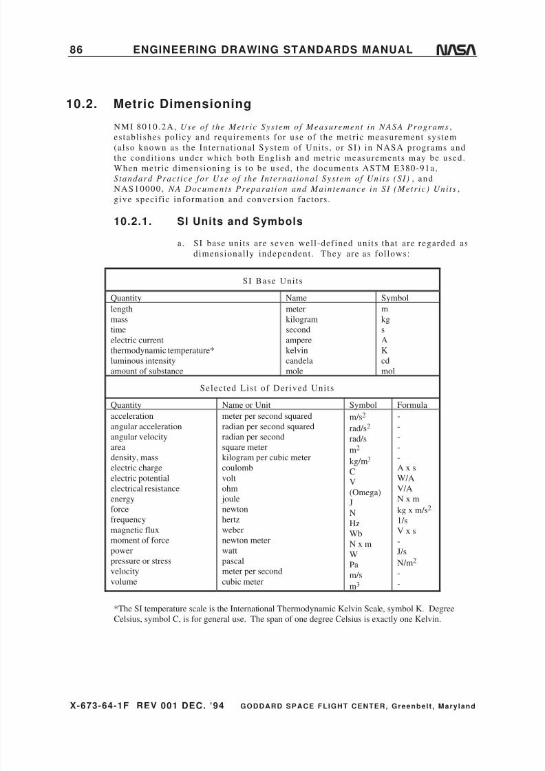
8/6/2019 Engineering Drawing Standards Manual GSFC-X-673!64!1F
http://slidepdf.com/reader/full/engineering-drawing-standards-manual-gsfc-x-673641f 98/128
X-673-64-1F REV 001 DEC. ‘94 GODDARD SPACE FLIGHT CENTER, Greenbelt , Mary land
86 ENGINEERING DRAWING STANDARDS MANUAL
10.2. Metric Dimensioning
NMI 8010.2A, Use of the Metric System of Measurement in NASA Programs ,
es tabl ishes pol icy and requirements for use of the metr ic measurement system(also known as the Internat ional System of Units , or SI) in NASA programs and
the condi t ions under which both Engl ish and metr ic measurements may be used.
When metr ic dimensioning is to be used, the documents ASTM E380-91a,
Standard Pract ice for Use of the Internat ional System of Uni ts (SI) , and
NAS10000, NA Documents Preparat ion and Maintenance in SI (Metric) Uni ts ,
give specif ic information and conversion factors .
10.2.1. SI Units and Symbols
a. SI base uni ts are seven wel l -def ined uni ts that are regarded as
dimensional ly independent . They are as fol lows:
SI Base Units
Quantity Name Symbol
length
mass
time
electric current
thermodynamic temperature*
luminous intensity
amount of substance
meter
kilogram
second
ampere
kelvin
candela
mole
m
kg
s
A
K
cd
mol
Selected List of Derived Units
Quantity Name or Unit Symbol Formulaacceleration
angular acceleration
angular velocity
area
density, mass
electric charge
electric potential
electrical resistance
energy
force
frequency
magnetic flux
moment of forcepower
pressure or stress
velocity
volume
meter per second squared
radian per second squared
radian per second
square meter
kilogram per cubic meter
coulomb
volt
ohm
joule
newton
hertz
weber
newton meterwatt
pascal
meter per second
cubic meter
m/s2
rad/s2
rad/s
m2
kg/m3
C
V
(Omega)
J
N
Hz
Wb
N x m
W
Pa
m/s
m3
-
-
-
-
-
A x s
W/A
V/A
N x m
kg x m/s2
1/s
V x s
-J/s
N/m2
-
-
*The SI temperature scale is the International Thermodynamic Kelvin Scale, symbol K. Degree
Celsius, symbol C, is for general use. The span of one degree Celsius is exactly one Kelvin.

8/6/2019 Engineering Drawing Standards Manual GSFC-X-673!64!1F
http://slidepdf.com/reader/full/engineering-drawing-standards-manual-gsfc-x-673641f 99/128
X-673-64-1F REV 001 DEC. ‘94 GODDARD SPACE FLIGHT CENTER, Greenbelt , Mary land
ENGINEERING DRAWING STANDARDS MANUAL 87
b. Dimensioning and tolerancing shal l be in SI uni ts and decimal
fract ions of the uni t . Al l l inear dimensions shal l be in
mil l imeters and decimal f ract ions of mil l imeters . Al though the
SI uni t for the plane angle is the radian, angles s tated indegrees, minutes , and seconds, or in degrees and decimal of a
degree (preferred) , shal l be used when dimensioning par ts . The
number of decimal places in the dimension shal l be the same as
the number of places in the required tolerance. The rounding of
dimensions and tolerancing shal l be in accordance with sect ion
10.2.2.2 on page 89. Drawings shal l be dimensioned and
toleranced in accordance with ANSI Y14.5M-1982.
c. Surface texture values shal l be noted in micrometers (m). See
the fol lowing table:
Surface Texture Conversion Values
Micrometers Microinches
Roughness
Grade
Numbers
50
25
12.5
6.3
3.2
1.6
0.8
0.4
0.2
0.10.05
0.025
2000
1000
500
250
125
63
32
16
8
42
1
N12
N11
N10
N9
N8
N7
N6
N5
N4
N3N2
N1
d. Forces, such as tensi le and shear loads, shal l be shown in
newtons (N) .
e . Stresses shal l be shown in megapascals (MPa = Pa x 106 ) . The
fol lowing table gives examples:
Ult imate Strength
Engl ish (PSI) SI (MPa)
Tensi le Shear Tensi le Shear
85 ,000
125,000
160,000
180,000
220,000
260,000
50,000
75,000
95,000
110,000
132,000
156,000
600
900
1,100
1,250
1,550
1,800
340
540
660
750
930
1,080
f . Pressure values for l iquid and gas shal l be shown in ki lopascals
(kPa = Pa x 103 ) .

8/6/2019 Engineering Drawing Standards Manual GSFC-X-673!64!1F
http://slidepdf.com/reader/full/engineering-drawing-standards-manual-gsfc-x-673641f 100/128
X-673-64-1F REV 001 DEC. ‘94 GODDARD SPACE FLIGHT CENTER, Greenbelt , Mary land
88 ENGINEERING DRAWING STANDARDS MANUAL
g. Mass values shal l be shown in ki lograms (kg) .
h. Preferred diameter /pi tch combinat ions for threaded fasteners are
shown in the fol lowing table, in accordance with ISO/TC20/SC4Resolut ions 169 and 220.
Dash Numbers
Thread Size Nominal Size
First
Oversize
(0.5 mm)
Second
Oversize
(1 mm)
1.0 x 0.25
1.2 x 0.25
1.6 x 0.35
2.0 x 0.402.5 x 0.45
3.0 x 0.50
3.5 x 0.60
4.0 x 0.70
5.0 x 0.80
6.0 x 1.0
7.0 x 1.0
8.0 x 1.0
10.0 x 1.25
12.0 x 1.2514.0 x 1.50
16.0 x 1.50
18.0 x 1.50
20.0 x 1.50
22.0 x 1.5
24.0 x 2.0
27.0 x 2.0
30.0 x 2.0
33.0 x 2.0
36.0 x 2.039.0 x 2.0
-010
-012
-016
-020-025
-030
-035
-040
-050
-060
-070
-080
-100
-120-140
-160
-180
-200
-220
-240
-270
-300
-330
-360-390
-
-
-
--
-
-
-
-055
-065
-075
-085
-105
-125-145
-165
-185
-205
-225
-245
-275
-305
-335
-365-395
-
-
-
--
-
-
-
-
-
-
-090
-110
-130-150
-170
-190
-210
-230
-250
-280
-310
-340
-370-400

8/6/2019 Engineering Drawing Standards Manual GSFC-X-673!64!1F
http://slidepdf.com/reader/full/engineering-drawing-standards-manual-gsfc-x-673641f 101/128
X-673-64-1F REV 001 DEC. ‘94 GODDARD SPACE FLIGHT CENTER, Greenbelt , Mary land
ENGINEERING DRAWING STANDARDS MANUAL 89
i . The tolerance block on the GSFC drawing format shal l be in
accordance with the format example in Figure 2b on page 6.
Tolerances given in the format may be adjusted to ref lect therequirements of the design.
j . Preferred Metric Limits & Fi ts (ANSI B4.2-1978) encompasses
tolerance required designat ions, preferred l imits , basic s izes ,
and symbols .
k . General Tolerances for Metric Dimensioned Products (ANSI
B4.3-1978) is used for metr ic dimensions without tolerance
designat ions.
10.2.2. Unit Conversions
10.2.2.1. Conversion of Dimensions
Following is a table of selected conversion factors . I f fur ther conversion factors
are needed, the references out l ined in paragraph 10.2 on page 86 are very useful .
To Convert From: To: Multiply By:
inch
in2
foot
ft2
lblbf/in2 (psi)
meter
m2
meter
m2
kgPa
2.540000 E–2*
6.451600 E–4*
3.048000 E–1*
9.290304 E–2*
4.5359237 E–1*
6.894757 E3
degrees Fahrenheit
degrees Fahrenheit
degrees Celsius
kelvin
tC = (tF – 32)/1.8*
tK = (tF + 459.67)/1.8*
*Exact conversion
10.2.2.2. Unit Rounding
a. General Rounding Rules
When a f igure is to be rounded to fewer digi ts than the total
number avai lable and the f i rs t digi t discarded is less than 5, the
last digi t retained should not be changed. For example,3.46325, i f rounded to three decimal places ( i .e . , 4 s ignif icant
digi ts or s imply 4 digi ts) , would be 3.463; i f rounded to three
signif icant digi ts , 3.46.
When the f i rs t digi t discarded is greater than 5, or i f i t i s a 5
fol lowed by at least one digi t other than 0, the last digi t
retained should be increased by one uni t . For example 8.37652,
i f rounded to four digi ts , would be 8.377; i f rounded to three
digi ts , 8.38.

8/6/2019 Engineering Drawing Standards Manual GSFC-X-673!64!1F
http://slidepdf.com/reader/full/engineering-drawing-standards-manual-gsfc-x-673641f 102/128
X-673-64-1F REV 001 DEC. ‘94 GODDARD SPACE FLIGHT CENTER, Greenbelt , Mary land
90 ENGINEERING DRAWING STANDARDS MANUAL
When the f i rs t digi t discarded is exact ly 5, fol lowed only by
zeros, the last digi t retained ( i .e . , the digi t preceding the 5,
underl ined in the examples below) should be rounded upward i f
i t i s an odd number, but no adjustment made i f i t i s an evennumber. For example, 4.365, when rounded to three s ignif icant
digi ts , becomes 4.36. The number 4.355 would also round to
the same value, 4.36, i f rounded to three s ignif icant digi ts .
This procedure is known as “odd-even rounding.”
Example: Round 46.02500 to two decimal places.
Answer : 46 .02
Example: Round 41.27500 to two decimal places.
Answer : 41 .28
General ly, the accuracy of the number of s ignif icant digi ts to
which a value is to be rounded must be known before a
conversion factor is used. I f this is not known, then the best
rule of thumb is to round the f inal value to the number of
s ignif icant digi ts corresponding to the least number of
s ignif icant digi ts of the or iginal , unconverted numbers . For
example, to convert 11.4 feet ( f t ) to meters (m):
11 .4 x 0 .3048 = 3 .47472, which rounds to 3 .47 meters . Nei ther
the conversion factor nor the quant i ty shal l be rounded before
performing the mult ipl icat ion, because accuracy would be
reduced. For convert ing inches ( in) to mil l imeters (mm), which
would general ly be the case in drawings, the rule of thumb is to
round to one less decimal place than the or iginal inchdimension. When convert ing from mil l imeters to inches, the
rule is to round to two more decimal places than the or iginal
value.
Example: Convert 3.5748 inches to mil l imeters .
3 .5748 x 25 .4 = 90 .79992 Answer : 90 .800 mm
Example: Convert 1.625 inches to mil l imeters .
1 .625 x 25 .4 = 41 .275 Answer : 41 .28 mm
Example: Convert 101.83 mil l imeters to inches.
101.83/25 .4 = 4 .009055118 Answer : 4 .0091 inches
b. Rounding Basic Dimensions
To convert basic dimensions of drawings from inches to
mil l imeters , the converted value shal l be rounded to three
decimal places s ince this shal l provide a maximum conversion
error of 0.00002 inch. In convert ing basic dimensions from
mil l imeters to inches, the value shal l be rounded to f ive decimal
places, giving a maximum conversion error of 0.000005 inch.
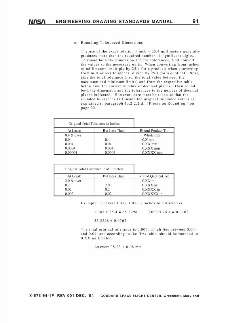
8/6/2019 Engineering Drawing Standards Manual GSFC-X-673!64!1F
http://slidepdf.com/reader/full/engineering-drawing-standards-manual-gsfc-x-673641f 103/128

8/6/2019 Engineering Drawing Standards Manual GSFC-X-673!64!1F
http://slidepdf.com/reader/full/engineering-drawing-standards-manual-gsfc-x-673641f 104/128
X-673-64-1F REV 001 DEC. ‘94 GODDARD SPACE FLIGHT CENTER, Greenbelt , Mary land
92 ENGINEERING DRAWING STANDARDS MANUAL
d. Precis ion Rounding (Inside)
When converted, tolerances must never exceed the or iginal ly
specif ied l imits (as in the case where the “converted” par ts areto be inspected by gages made for the or iginal par ts) . The
round-off must be such that the new dimensions shal l l ie inside
the or iginal tolerance l imits . This may be accomplished by
convert ing the maximum and minimum l imits exact ly, and then
rounding the upper l imit to the next lower value and rounding
the lower l imit to the next higher value.
Example: Convert 0.877 from inches to mil l imeters without
0 .874
violat ion of the or iginal l imits :
0 .877 x 25 .4 = 22 .2758; 0 .874 x 25 .4 = 22 .1996
The total or iginal tolerance is 0.003, which l ies between 0.0004
and 0.004 and, according to the preceding table, should be
rounded to 0.XXX mil l imeters .
Answer : 22 .275 mm
22.200 mm
Note that 22.2758 is not rounded to 22.276 mm because i t would
violate the “inside” rule.
10.3. Design References
a. Finishes of Metal and Wood Surfaces: MIL-STD-171. Reference document( for a working knowledge) : MIL-HDBK-132A.
b. Gears/Gear Classi f icat ion and Inspect ion Handbook Tolerances and Measuring
Methods for Unassembled Spur and Hel ical Gears ( including metr ic
equivalents) : AGMA 2000-A-88.
c. Gear Classi f icat ion, Mater ials , and Measuring Methods for Bevel , Hypoid,
Fine Pi tch Wormgearing, and Racks Only as Unassembled Gears:
AGMA 390.03A-88.
d. Opt ics/General Specif icat ion Governing the Manufacture, Assembly, and
Inspect ion of Opt ical Components for Fire Control Inst ruments: MIL-O-13830
.
e. Solder ing/Gener al Specif icat ion for Solder ing Process ( for nonelectr ical
appl icat ions) : MIL-S-6872.
f . Springs/Drawin g Requirements for Mechanical Springs: MIL-STD-29.
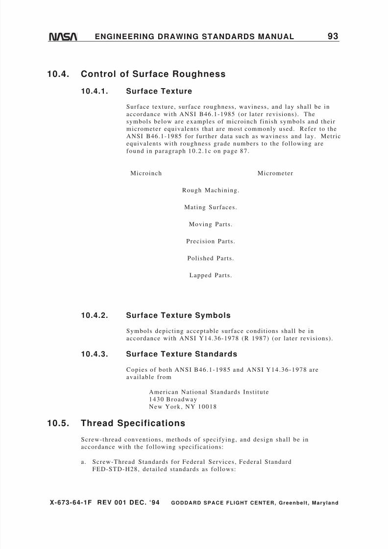
8/6/2019 Engineering Drawing Standards Manual GSFC-X-673!64!1F
http://slidepdf.com/reader/full/engineering-drawing-standards-manual-gsfc-x-673641f 105/128
8/6/2019 Engineering Drawing Standards Manual GSFC-X-673!64!1F
http://slidepdf.com/reader/full/engineering-drawing-standards-manual-gsfc-x-673641f 106/128
X-673-64-1F REV 001 DEC. ‘94 GODDARD SPACE FLIGHT CENTER, Greenbelt , Mary land
94 ENGINEERING DRAWING STANDARDS MANUAL
FED-STD-H28/1 Nomenclature, Defini t ions, and Let ter Symbols for Screw
Threads.
FED-STD-H28/2 Unif ied Thread Form and Thread Series for Bol ts , Screws,Nuts , Tapped Holes , and General Appl icat ions.
FED-STD-H28/3 Unif ied Threads of Special Diameter , Pi tches, and Lengths of
Engagement .
FED-STD-H28/4 Control led Radius Root Screw Threads, UNJ Symbol .
FED-STD-H28/5 Unif ied Miniature Screw Threads.
FED-STD-H28/6 Gages and Gaging for Uni f ied Screw Threads .
FED-STD-H28/7 American Standard Pipe Threads (except Dryseal and Hose
Coupl ing Types) .
FED-STD-H28/8 Dryseal American Standard Pipe Threads.
FED-STD-H28/9 Gas Cyl inder Valve Outlet and Inlet Threads.
FED-STD-H28/10 American Nat ional Hose Coupl ing and Fire-Hose Coupl ing
Threads.
FED-STD-H28/11 Hose Connect ions for Welding and Cut t ing Equipment .
FED-STD-H28/12 Acme Threads.
FED-STD-H28/13 Stub Acme Threads.
FED-STD-H28/14 Nat ional But t ress Threads.
FED-STD-H28/15 American Standard Rol led Threads for Screw Shel ls of
Electr ic Lamp Holders and for Screw Shel ls of Unassembled Lamp Bases.
FED-STD-H28/16 Microscope Object ive and Nosepiece Threads, 0.800—
36AMO.
FED-STD-H28/17 Surveying Instrument Mounting Threads.
FED-STD-H28/18 Photographic Equipment Threads.
FED-STD-H28/19 Miscel laneous Threads.
FED-STD-H28/20 Inspect ion Methods for Acceptabi l i ty of UN, UNR, UNJ, M,
and MJ Screw-Threads.
FED-STD-H28/21A Metr ic Screw-Thread Standards.
FED-STD-H28/22 Metr ic Screw-Thread Gages.
b. General Specif icat ion for Screw Threads, Standard, Opt imum Selected Series ,
Mil i tary Specif icat ion MIL-S-7742.

8/6/2019 Engineering Drawing Standards Manual GSFC-X-673!64!1F
http://slidepdf.com/reader/full/engineering-drawing-standards-manual-gsfc-x-673641f 107/128
X-673-64-1F REV 001 DEC. ‘94 GODDARD SPACE FLIGHT CENTER, Greenbelt , Mary land
ENGINEERING DRAWING STANDARDS MANUAL 95
c. General Requirements for Pipe Threads, Taper , Aeronaut ical Nat ional Form,
Symbol-ANPT, Mil i tary Specif icat ion MIL-P-7105.
d. General Specif icat ion for Screw Threads, Control led Radius Root WithIncreased Minor Diameter , Mil i tary Specif icat ion MIL-S-8879.
e. Metr ic Screw Threads M Profi le ANSI/ASME B1.13M-1983.
f . Metr ic Screw Threads MJ Profi le ANSI B1.21M-1978 .
g. Screw Thread Representat ion s (Convent ions and Methods of Specifying) ,
American Nat ional Standard ANSI Y14.6-1978, and ANSI Y14.6aM-1981
(Metr ic Supplement) .
10.6. Welding—Fusion and Resistance
10.6.1. General
The standard def ini t ion for the term “weld” is a local ized
coalescence of metals where coalescence is produced by heat ing to
sui table temperatures , wi th or without the appl icat ion of pressure,
and with or without the use of f i l ler metal . The f i l ler metal ei ther
has a mel t ing point approximately the same as the base metal or has
a mel t ing point below that of the base metal but above 800 degrees
F. For s tandard welding specif icat ion cal louts , refer to “Joining
Method Notes ,” paragraph 2 .4 .4 .3 on page 18 .
10.6.2. Basic Weld Symbols and Their Location
Significance
Basic weld symbols and their locat ion s ignif icance shal l be in
accordance with ANSI AWS A 2.4-86 (or later revis ions) .
Copies are avai lable f rom
American Welding Society
2501 NW 7th St ree t
Miami, FL 33125
10.7. Outgassing of Spacecraft Materials
NASA Reference Publ icat ion, RP-1124, November 1990, Outgassing Data for
Select ing Spacecraf t Materials , covers a wide range of mater ials , including
adhesives, compounds, coat ings, insulat ion, and var ious other mater ials . As
presented, the data represent the “total mass loss” (TML) and the “Collected
Volat i le Condensable Mater ials” (CVCM), as der ived from tests at 398 K (125 C)
for 24 hours in vacuum per ASTM E595-84.
The publ icat ion can be purchased as document number N-88-10117 from

8/6/2019 Engineering Drawing Standards Manual GSFC-X-673!64!1F
http://slidepdf.com/reader/full/engineering-drawing-standards-manual-gsfc-x-673641f 108/128
X-673-64-1F REV 001 DEC. ‘94 GODDARD SPACE FLIGHT CENTER, Greenbelt , Mary land
96 ENGINEERING DRAWING STANDARDS MANUAL
National Technical Information Service (NTIS)
5285 Por t Royal Road
Spr ingf ie ld , VA 22151
10.8. Standards and Specifications Index
10.8.1. National Bureau of Standards
NBS IR81-229, A Technical Brief ing on the Ini t ial Graphics
Exchange Specif icat ion (IGES).
10.8.2. Federal
Commerce Commission Regulat ion 49-CFR71-78 Commerce
Commission Safety Regulat ions
Commercial and Government Ent i ty (CAGE) Publ icat ion H4/H8
Sect ion A: Name to CAGE Code; Sect ion B: CAGE Code to
Name (formerly FSCM H4 and FSCNM H8).
FED-STD-H28/1, Nomenclature, Defini t ions, and Let ter Symbols
for Screw Threads.
FED-STD-H28/2, Unif ied Thread Form and Thread Series for Bol ts .
FED-STD-H28/3, Unif ied Threads of Special Diameter , Pi tches, and
Lengths of Engagement .
FED-STD-H28/4, Cont ro l l ed Radius Root Screw Threads , UNJSymbol .
FED-STD-H28/5, Unif ied Miniature Screw Threads.
FED-STD-H28/6 , Gages and Gaging for Uni f ied Screw Threads .
FED-STD-H28/7, American Standard Pipe Threads (except Dryseal
and Hose Coupl ing Types.
FED-STD-H28/8, Dryseal American Standard Pipe Threads.
FED-STD-H28/9, Gas Cyl inder Valve Outlet and Inlet Threads.
FED-STD-H28/10, American Nat ional Hose Coupl ing and Fire-
Hose .
FED-STD-H28/11, Hose Connect ions for Welding and Cut t ing
Equipment .
FED-STD-H28/12, Acme Threads .
FED-STD-H28/13, S tub Acme Threads .
FED-STD-H28/14, Nat ional But t ress Threads.

8/6/2019 Engineering Drawing Standards Manual GSFC-X-673!64!1F
http://slidepdf.com/reader/full/engineering-drawing-standards-manual-gsfc-x-673641f 109/128
X-673-64-1F REV 001 DEC. ‘94 GODDARD SPACE FLIGHT CENTER, Greenbelt , Mary land
ENGINEERING DRAWING STANDARDS MANUAL 97
FED-STD-H28/15, American Standard Rol led Threads for Screw
Shel ls for Electr ic Lamp Holders & Unassembled Lamp Bases.
FED-STD-H28/16, Microscope Object ive and Nosepiece Threads.
FED-STD-H28/17, Surveying Instrument Mounting Threads.
FED-STD-H28/18, Photographic Equipment Threads.
FED-STD-H28/19, Miscel laneous Threads.
FED-STD-H28/20, Inspect ion Methods for Acceptabi l i ty of UN,
UNR, UNJ, M, and MJ Screw-Threads .
FED-STD-H28/21, Metr ic Screw-Thread Standards.
FED-STD-H28/22, Metr ic Screw-Thread Gages.
FED-STD-595, Colors .
QQ-B-654, Brazing Alloys, Si lver .
QQ-C-320, Chromium Plat ing (Electrodeposi ted) .
QQ-P-35, Passivat ion Treatments for Corrosion-Resis tant Steel .
QQ-P-416, Plat ing, Cadmium (Electrodeposi ted) .
QQ-S-365, Si lver Plat ing (Electrodeposi ted) , General Requirements
for .
QQ-S-571, Solder , Tin Alloy, Tin-Lead Alloy, and Lead Alloy.
Safety Regulat ions 49-CFR71-78, Commerce Commission Safety
Regulat ions.
10.8.3. Industrial
AGMA 390.03A-88, Gear Classi f icat ion and Inspect ion Handbook
Tolerances and Measuring Methods for Bevel , Hypoid, Fine
Pi tch Wormgearing, and Racks.
AGMA 2000-A-88, Gear Classi f icat ion and Inspect ion Handbook Tolerances and Measuring Methods for Unassembled Spur and
Helical Gears ( Including Metr ic Equivalents) .
AMS 2488, Anodic Treatment of Ti tanium and Ti tanium Alloys.
ANSI AWS A2.4-1986, Symbols for Welding and Nondes t ruc t ive
Test ing.
ANSI/ASME B1.13M-1983, Metr ic Screw Threads M Profi le .
ANSI B1.21M-1978, Metr ic Screw Threads MJ Profi le .

8/6/2019 Engineering Drawing Standards Manual GSFC-X-673!64!1F
http://slidepdf.com/reader/full/engineering-drawing-standards-manual-gsfc-x-673641f 110/128
X-673-64-1F REV 001 DEC. ‘94 GODDARD SPACE FLIGHT CENTER, Greenbelt , Mary land
98 ENGINEERING DRAWING STANDARDS MANUAL
ANSI B4.2-1978, Preferred Metr ic Limits and Fi ts .
ANSI B4.3-1978 General Tolerances for Metr ic Dimensioned
Products .
ANSI B46.1-1985, Surface Texture (Surface Roughness, Waviness ,
and Lay) .
ANSI Y14.15-1966 (R-73) , Electr ical and Electronics Diagrams.
ANSI Y14.15a-1971, Interconnect ion Diagrams.
ANSI Y14.15b-1973, Electr ical and Electronics Diagrams.
ANSI Y14.2M-1979, Line Convent ions and Let ter ing.
ANSI Y14.26M-1987, Digi tal Representat ion for Communicat ion of Product Defini t ion Data.
ANSI Y14.36-1978 (R1987) , Sur face Texture Symbols .
ANSI Y14.5M-1982, Dimensioning and Tolerancing.
ANSI Y14.6-1978, Screw Thread Representa t ion .
ANSI Y14.6AM-1981, Screw Thread Representat ion (Metr ic
Supplement) .
ANSI Y32.2-1975, IEEE STD 315-1975, CSA Z99-1975, Graphic
Symbols for Electr ical and Electronics Diagrams.
ANSI Y32.9-1972, Graphic Symbols for Electr ical Wiring and
Layout Diagrams Used in Archi tecture and Bui lding
Construct ion.
ASTM D4126, Vapor Degreas ing .
ASTM E380-91a, Standard Pract ice for Use of the Internat ional
System of Units (The Modernized Metr ic System).
ASTM E595-84, Standard Test Method for Total Mass Loss and
Collected Volat i le Condensible Mater ials From Outgassing in a
Vacuum Environment .
N-88-10117, Nat ional Technical Information Service—Outgassing
Data for Select ing Spacecraf t Mater ials .
NAS10000, NA Documents Preparat ion and Maintenance in SI
(Metr ic) Uni ts .
10.8.4. Military
DOD-STD-1866, Solder ing Specif icat ion.

8/6/2019 Engineering Drawing Standards Manual GSFC-X-673!64!1F
http://slidepdf.com/reader/full/engineering-drawing-standards-manual-gsfc-x-673641f 111/128
X-673-64-1F REV 001 DEC. ‘94 GODDARD SPACE FLIGHT CENTER, Greenbelt , Mary land
ENGINEERING DRAWING STANDARDS MANUAL 99
MIL-A-8625, Anodic Coat ings, for Aluminum and Aluminum
Alloys.
MIL-B-7883, Brazing of Steels , Copper , Copper Alloys, NickelAlloys, Aluminum, and Aluminum Alloys.
MIL-C-5541, Chemical Conversion Coat ings on Aluminum and
Aluminum Alloys.
MIL-C-12968, Coat ings, Phosphate, Protect ive.
MIL-C-13924, Coat ing, Oxide, Black, for Ferrous Metals .
MIL-D-5480, Data, Engineer ing and Technical , Reproduct ion
Requirements for .
MIL-H-6088, Heat Treatment of Aluminum Alloys.
MIL-H-6875, Heat Treatment of Steel , Processes for .
MIL-H-7199, Heat Treatment of Wrought Copper-Beryl l ium Alloys,
Process for .
MIL-HDBK-132A, Protect ive Finishes for Metal and Wood
Surfaces.
MIL-I-45932/1, Inser t , Screw Thread - Thin Wall , Locked in.
MIL-L-46010, Lubricant , Sol id Fi lm, Heat Cured, Corrosion.
MIL-M-9868, Microf i lming of Engineer ing D ocuments , 35MM,
Requirements for .
MIL-N-45938/1, Nut , Plain, Cl inch (Self-Cl inching, Round) .
MIL-O-13830, Opt ical Components for Fire Control Inst ruments;
General Specif icat ion Governing the Manufactur ing, Assembly,
and Inspect ion of .
MIL-P-116, Preservat ion, Methods of .
MIL-P-7105, Pipe Threads, Taper , Aeronaut ical Nat ional Form,
Symbol ANPT, General Requirement for .
MIL-R-28002, Raster Graphics Representat ion in Binary Format ,
Requirements for .
MIL-S-6872, General Specif icat ion for Solder ing Process (non-
electr ical) .
MIL-S-7742, Screw Threads, STD, Optimum Selected Series ,
General Specif icat ion for .
8/6/2019 Engineering Drawing Standards Manual GSFC-X-673!64!1F
http://slidepdf.com/reader/full/engineering-drawing-standards-manual-gsfc-x-673641f 112/128
X-673-64-1F REV 001 DEC. ‘94 GODDARD SPACE FLIGHT CENTER, Greenbelt , Mary land
100 ENGINEERING DRAWING STANDARDS MANUAL
MIL-S-8879, Screw Threads, Control led Radius Root With
Increased Minor Diameter ; General Specif icat ion for .
MIL-STD-12, Abbreviat ion s.
MIL-STD-29, Drawing Requirements for Mechanical Springs.
MIL-STD-100, Engineer ing Drawing Pract ices .
MIL-STD-171, Finishes of Metal and Wood Surfaces.
MIL-STD-403, Preparat ion for and Instal lat ion of Rivets and
Screws, Rocket and Missi le Structures .
MIL-STD-00453, Radiographic Inspec t ion.
MIL-STD-645, Dip Brazing of Aluminum Alloys.
MIL-STD-2154, Ult rasonic Inspect ion.
MIL-STD-2219, Fusion Welding for Aerospace Appl icat ions.
MIL-T-713, Twine, Fibrous; Impregnated, Lacing and Tying.
MIL-W-46132, Electronic Beam Welding.
MS33537, Inser t , Screw Thread, Hel ical Coi l , Coarse and Fine
Thread, Standard Dimensions for .
MS51835, Inser ts and Studs, Locked In-Key Locked, HoleDimensions for and Assembly of .
10.8.5. NASA
GSFC 731-0005-83, General Fracture Control Plan for Payloads
Using the Space Transportat ion System (STS).
GSFC-GHB-2200.2, Scient i f ic and Technical Information
Handbook.
GSFC S-250-3, Guide for the Preparat ion of Specif icat ions.
GSFC S-313-009, Fluorescent Penetrant Test Method Requirementsand Guidel ines.
GSFC S-313-100, GSFC Fastener Integri ty Requirements .
GSFC-STD-256-WE-1, For Your Information, A Compendium of
General Reference Data for Technical Wri t ing and Edi t ing.
GSFC X-673-64-1F, GSFC Engineer ing Standards Design Manual .
NASA Reference Publ icat ion RP-1124, November 1990, Outgassing
Data for Select ing Spacecraf t Mater ials .

8/6/2019 Engineering Drawing Standards Manual GSFC-X-673!64!1F
http://slidepdf.com/reader/full/engineering-drawing-standards-manual-gsfc-x-673641f 113/128
X-673-64-1F REV 001 DEC. ‘94 GODDARD SPACE FLIGHT CENTER, Greenbelt , Mary land
ENGINEERING DRAWING STANDARDS MANUAL 101
NHB 5300.4 (3A-l) 1976, Requirements for Soldered Electr ical
Connect ions.
NMI 80102A, Use of the Metr ic System of Measurement in NASAPrograms.
NSTS 07700, System Descript ion and Design Data, Intervehicular
Act ivi t ies .
10.9. Standards and Specifications Numerical Index
Specif icat ion Page
AGMA 2000-A-88, Gear Classi f icat ion and Inspect ion
Handbook Tolerances and Measuring Methods for
Unassembled Spur and Hel ical Gears ( Including Metr ic
Equivalents) . 92
AGMA 390.03A-88, Gear Classi f icat ion Mater ials and
Measuring Methods for Bevel , Hypoid, Fine Pi tch
Wormgearing, and Racks. 92
AMS 2488, Anodic Treatment of Ti tanium and Ti tanium
Al loys . 19
ANSI AWS A 2 .4-86 , Symbols for Welding and
Nondestruct ive Test ing. 95
ANSI B1.21M-197 8, Metr ic Screw Threads MJ Profi le 95
Specif icat ion Page
ANSI B4.2-1978, Preferred Metr ic Limits and Fi ts . 89
ANSI B46.1-1985, Surface Texture (Surface Roughness,
Waviness , and Lay) . 93
ANSI Y14.15-1966 (R-73) , Electr ical and Electronics
Diagrams. 43
ANSI Y14.15a-19 71, Interconnect ion Diagrams. 43
ANSI Y14.15b-1 973, Electr ical and Electronics Diagrams. 43
ANSI Y14.2M-197 9, Line Convent ions and Let ter ing. 35
ANSI Y14.26M-1987, Digi tal Representat ion for
Communicat ion of Product . 84
ANSI Y14.36-1978 (R 1987) , Sur face Texture Symbols . 93
ANSI Y14.5M-1982, Dimensioning and Tolerancing.
1 , 7 , 16 , 28 , 85 , 87 , 107, 108

8/6/2019 Engineering Drawing Standards Manual GSFC-X-673!64!1F
http://slidepdf.com/reader/full/engineering-drawing-standards-manual-gsfc-x-673641f 114/128
X-673-64-1F REV 001 DEC. ‘94 GODDARD SPACE FLIGHT CENTER, Greenbelt , Mary land
102 ENGINEERING DRAWING STANDARDS MANUAL
ANSI Y14.6-1978, Screw Thread Representat ion . 95
ANSI Y14.6aM-1981, Screw Thread Representat ion (Metr ic
Supplement) . 95
ANSI Y32.2-1975, IEEE STD 315-1975, CSA Z99-1975,
Graphic Symbols for Electr ical and Electronic Diagrams. 43
ANSI Y32.9-1972, Graphic Symbols for Electr ical Wiring
and Layout Diagrams Used in Archi tecture and Bui lding
Cons t ruc t ion . 43
ANSI/ASME B1.13M-1983, Metr ic Screw Threads M Profi le 95
ASTM D4126, Vapor Degreas ing. 20
ASTM E380-91a, Standard Pract ice for Use of theInternat ional System of Units (The Modernized Metr ic
System). 86
ASTM E595-84, Standard Test Method for Total Mass Loss
and Col lected Volat i le Condensible Mater ials From
Outgassing in a Vacuum Environment . 95
Commerce Commission Regulat ion 49-CFR71-78, Commerce
Commission Safety Regulat ions. 22
Commercial and Government Ent i ty (CAGE) Publ icat ion
H4/H8. 7 , 72 , 75
Specif icat ion Page
DOD-STD-1 866, Solder ing Specif icat ion. 18
FED-STD-595, Colors 19
FED-STD-H28/1, Nomenclature, Defini t ions, and Let ter
Symbols for Screw Threads. 93
FED-STD-H28/2, Unif ied Thread Form and Thread Series
for Bol t s , Screws , Nuts , Tapped Holes , and Genera l
Appl ica t ions . 93
FED-STD-H28/3, Unif ied Threads of Special Diameter ,
Pi tches, and Lengths of Engagements . 93
FED-STD-H28/4, Control led Radius Root Screw Threads,
UNJ Symbol . 93
FED-STD-H2 8/5, Unif ied Miniature Screw Threads. 93
FED-STD-H28/6, Gages and Gaging for Uni f ied Screw
Threads . 93

8/6/2019 Engineering Drawing Standards Manual GSFC-X-673!64!1F
http://slidepdf.com/reader/full/engineering-drawing-standards-manual-gsfc-x-673641f 115/128
X-673-64-1F REV 001 DEC. ‘94 GODDARD SPACE FLIGHT CENTER, Greenbelt , Mary land
ENGINEERING DRAWING STANDARDS MANUAL 103
FED-STD-H28/7, American Standard Pipe Threads (except
Dryseal and Hose Coupl ing Types) . 93
FED-STD-H2 8/8, Dryseal American Standard Pipe Threads. 93
FED-STD-H28/9, Gas Cyl inder Valve Outlet and Inlet
Threads . 93
FED-STD-H28/10, American Nat ional Hose Coupl ing and
Fi re-Hose Coupl ing Threads . 93
FED-STD-H28/11, Hose Connect ions for Welding and
Cutt ing Equipment . 93
FED-STD-H28/12, Acme Threads . 93
FED-STD-H28/13, S tub Acme Threads . 93
FED-STD-H2 8/14, Nat ional But t ress Threads. 93
FED-STD-H28/15, American Standard Rol led Threads for
Screw Shel ls of Electr ic Lamp Holders and for Screw
Shel ls of Unassembled Lamp Bases. 93
FED-STD-H28/16, Microscope Object ive and Nosepiece
Threads , 0 .800-36AMO. 93
FED-STD-H 28/17, Surveying Instrument Mounting Threads. 93
FED-STD-H 28/18, Photographic Equipment Threads. 93
Specif icat ion Page
FED-STD-H2 8/19, Miscel laneous Threads. 93
FED-STD-H28/20, Inspect ion Methods for Acceptabi l i ty of
UN, UNR, UNJ, M, and MJ Screw-Threads . 94
FED-STD-H2 8/21A, Metr ic Screw-Thread Standards. 94
FED-STD-H2 8/22, Metr ic Screw-Thread Gages. 94
GSFC 731-0005-83, General Fracture Control Plan forPayloads Using the Space Transportat ion System (STS). 20
GSFC S-250-3, Guide for the Preparat ion of Specif icat ions. 60
GSFC S-313-009, Fluorescent Penetrant Test Method
Requirements and Guidel ines. 20
GSFC S-313-100, GSFC Fastener Integri ty Requirements . 14
GSFC STD-256-WE-1, For Your Informat ion—A
Compendium Of General Reference Data. 12

8/6/2019 Engineering Drawing Standards Manual GSFC-X-673!64!1F
http://slidepdf.com/reader/full/engineering-drawing-standards-manual-gsfc-x-673641f 116/128
X-673-64-1F REV 001 DEC. ‘94 GODDARD SPACE FLIGHT CENTER, Greenbelt , Mary land
104 ENGINEERING DRAWING STANDARDS MANUAL
GSFC X-673-64-1F, GSFC Engineer ing Drawing Standards
Manual . i i i , 16, 21
MIL-A-8625, Anodic Coat ings, for Aluminum and AluminumAl loys . 19
MIL-B-7883, Brazing of Steels , Copper , Copper Alloys,
Nickel Alloys, Aluminum, and Aluminum Alloys. 18
MIL-C-5541, Chemical Conversion Coat ings on Aluminum
and Aluminum Alloys. 19
MIL-C-12968, Coat ings, Phosphate, Protect ive. 19
MIL-C-13924, Coat ing, Oxide, Black, for Ferrous Metals . 109
MIL-D-5480, Data, Engineer ing and Technical ,Reproduct ion Requirements for . 83
MIL-H-6088, Heat Treatment of Aluminum Alloys. 17, 18
MIL-H-6875, Heat Treatment of Steel , Processes for . 17
MIL-H-7199, Heat Treatment of Wrought Copper-Beryl l ium
Al loys , Process for . 17
MIL-HDBK-132A, Protect ive Finishes for Metal and Wood
Surfaces . 92
Specif icat ion Page
MIL-I-45932/1, Inser t , Screw Thread - Thin Wall , Locked
In . 21
MIL-L-46010, Lubricant , Sol id Fi lm, Heat Cured, Corrosion.20, 109
MIL-M-9868, Microf i lming of Engineer ing Documents ,
35mm, Requirements for . 83
MIL-N-45938/1, Nut , Plain, Cl inch (Self-Cl inching, Round) . 21
MIL-O-13830, Opt ical Components for Fire Control
Instruments; General Specif icat ion Governing the
Manufactur ing, Assembly, and Inspect ion of . 92
MIL-P-116, Preservat ion, Methods of . 21, 22
MIL-P-7105, Pipe Threads, Taper , Aeronaut ical Nat ional
Form, Symbol ANPT, General Requirements for . 95
MIL-R-28002, Raster Graphics Representat ion in Binary
Format , Requirements for . 83

8/6/2019 Engineering Drawing Standards Manual GSFC-X-673!64!1F
http://slidepdf.com/reader/full/engineering-drawing-standards-manual-gsfc-x-673641f 117/128
X-673-64-1F REV 001 DEC. ‘94 GODDARD SPACE FLIGHT CENTER, Greenbelt , Mary land
ENGINEERING DRAWING STANDARDS MANUAL 105
MIL-S-6872, General Specif icat ion for Solder ing Process
(non-electr ical) . 92
MIL-S-7742, Screw Threads, STD, Optimum SelectedSeries , General Specif icat ion for . 94
MIL-S-8879, Screw Threads, Control led Radius Root with
Increased Minor . 95
MIL-STD-00453 , Radiographic Inspect ion. 20
MIL-STD-12, Abbrevia t ions . 12
MIL-STD-100E , Engineer ing Drawing Pract ices . 1
MIL-STD-171, Finishes of Metal and Wood Surfaces. 18, 92
MIL-STD-2154, Ult rasonic Inspect ion. 20
MIL-STD-2219, Fusion Welding for Aerospace
Appl ica t ions . 18
MIL-STD-29, Drawing Requirements for Mechanical
Spr ings . 92
MIL-STD-403, Preparat ion for and Instal lat ion of Rivets and
Screws, Rocket and Missi le Structures . 18
MIL-STD-645, Dip Brazing of Aluminum Alloys 18
Specif icat ion Page
MIL-T-713, Twine, Fibrous; Impregnated, Lacing and Tying. 22
MIL-W-46132, Electronic Beam Welding. 18
MS33537, Inser t , Screw Thread, Hel ical Coi l , Coarse and
Fine Thread, Standard Dimensions for . 21
MS51835, Inser t s and Studs , Locked In-Key Locked, Hole
Dimensions for and Assembly of . 21
N-88-10117, Nat ional Technical Information Service—Outgassing Data Compilat ion of Spacecraf t Mater ials . 95
NAS10000, NA Documents Preparat ion and Maintenance in
SI (Metr ic) Uni ts . 86
NASA Reference Publ icat ion, RP-1124, November 1990,
Outgassing Data for Select ing Spacecraf t Mater ials . 95, 108
NBS IR81-229, A Technical Brief ing on the Ini t ial Graphics
Exchange . 84
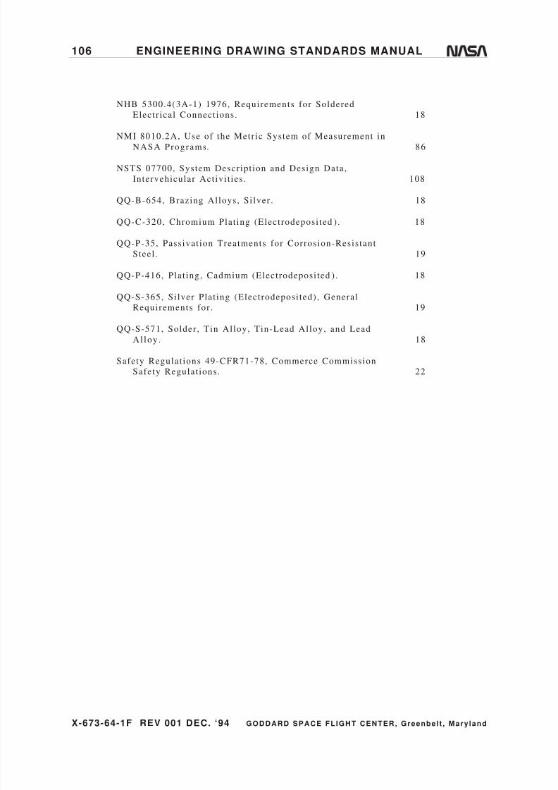
8/6/2019 Engineering Drawing Standards Manual GSFC-X-673!64!1F
http://slidepdf.com/reader/full/engineering-drawing-standards-manual-gsfc-x-673641f 118/128
X-673-64-1F REV 001 DEC. ‘94 GODDARD SPACE FLIGHT CENTER, Greenbelt , Mary land
106 ENGINEERING DRAWING STANDARDS MANUAL
NHB 5300.4(3A-1) 1976, Requirements for Soldered
Electr ical Connect ions. 18
NMI 8010.2A, Use of the Metr ic System of Measurement inNASA Programs. 86
NSTS 07700, System Descript ion and Design Data,
Intervehicular Act ivi t ies . 108
QQ-B-654, Brazing Alloys, Si lver . 18
QQ-C-320, Chromium Plat ing (Electrodeposi ted ) . 18
QQ-P-35, Passivat ion Treatments for Corrosion-Resis tant
Steel . 19
QQ-P-416, Plat ing, Cadmium (Electrodeposi ted ) . 18
QQ-S-365, Si lver Plat ing (Electrodeposi ted) , General
Requirements for . 19
QQ-S-571, Solder , Tin Alloy, Tin-Lead Alloy, and Lead
Al loy . 18
Safety Regulat ions 49-CFR71-78, Commerce Commission
Safety Regulat ions. 22

8/6/2019 Engineering Drawing Standards Manual GSFC-X-673!64!1F
http://slidepdf.com/reader/full/engineering-drawing-standards-manual-gsfc-x-673641f 119/128
X-673-64-1F REV 001 DEC. ‘94 GODDARD SPACE FLIGHT CENTER, Greenbelt , Mary land
ENGINEERING DRAWING STANDARDS MANUAL 107
APPENDIX A. DESIGN REVIEW DOs AND DON'Ts
All drawings should adhere to the fol lowing guidel ines:
a . Dimension parts correctly. Dimensioning shal l be to pr imary or mat ing
surfaces. Unwanted bui ldup of tolerances between mat ing surfaces should be
avoided. Dimensions to insignif icant theoret ical center l ines can resul t in
mistakes by the machinis t , as wel l as the inspectors , because of the mult iple
addi t ions and subtract ions required to locate the feature in relat ion to other
features . Whenever possible, dimensions should be lef t to r ight and bot tom to
top (Quadrant I , a l l posi t ive numbers) or f rom datums establ ished by design
requirements .
b. Do not detail weldment parts separate ly . Since each par t may be fabricated
by a different manufacturer , the required tolerancing typical ly cannot be met ,
resul t ing in delays and addi t ional cost . Different par ts of a weldment shouldbe drawn on an Inseparable Assembly Drawing (Figure 20 on page 44) so that
the overal l assembly tolerancing is the responsibi l i ty of a s ingle manufacturer .
c . Implied datums are no longer al lowed. Whenever possible, select datums
that are funct ional to the par t . A datum should always be assigned to a
physical surface or a feature of s ize. When using t rue posi t ion dimensioning
(basic dimensions) , the dimensions from the feature to other edges and i ts
perpendicular i ty relat ionship to a surface must be ident i f ied with datum
let ters . The combined usage of posi t ional tolerancing with plus and minus
methods as related to basic dimensioned pat terns is discont inued and replaced
with the composi te tolerancing method. Refer to ANSI Y14.5M-1982,
“Dimensioning and Tolerancing.”
Note :
Although there is no requirement that al l holes be t rue posi t ioned, i t i s
preferred that hole pat terns be t rue posi t ioned, regardless of use, s ince
tolerancing specif ied in the t rue posi t ion block is the control l ing factor .
d. Drawings for parts produced using templates must be properly
dimensioned and toleranced. Lack of dimensioning may resul t in inadequate
st ress analysis , f i t checking, and/or inspect ion. Engineer ing and tool ing
drawings should be dimensioned al ike and related to one another . Refer to
tool ing required notes in “Dimension Notes ,” paragraph 2.4.4.1 on page 16.
e. Use the l ist of material format correctly. The assembly number does not get
an i tem number. While the mater ial is properly an i tem on the List of Mater ial , on end product drawings, there is no need to specify ei ther the
drawing number or an i tem number in the List of Mater ial i f there is only one
part or mater ial . An i tem with the same mater ial and specif icat ion requires
only one i tem number and “A/R” (as required) as a quant i ty. The var ious
mater ial s izes required are indicated on the f ield of the drawing, as is the case
of inseparable assemblies (weldments , r iveted par ts , e tc .) . Dash numbers are
required only when there is a “shown” (odd number) and “opposi te” (even
number) , when there is more than one assembly version, or when the drawing
is of a tabulated type (refer to types of drawings) . Mult idetai l drawings are
not al lowed (refer to “Detai l Drawing,” paragraph 4.3 on page 41 for
explanat ion) .
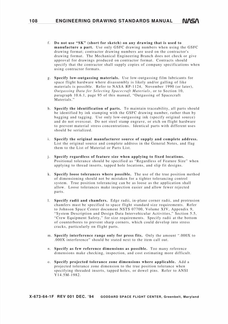
8/6/2019 Engineering Drawing Standards Manual GSFC-X-673!64!1F
http://slidepdf.com/reader/full/engineering-drawing-standards-manual-gsfc-x-673641f 120/128
X-673-64-1F REV 001 DEC. ‘94 GODDARD SPACE FLIGHT CENTER, Greenbelt , Mary land
108 ENGINEERING DRAWING STANDARDS MANUAL
f . Do not use “SK” (short for sketch) on any drawing that is used to
manufacture a part. Use only GSFC drawing numbers when using the GSFC
drawing format; contractor drawing numbers are used on the contractor 's
drawing format . The Mechanical Engineer ing Branch does not check or giveapproval for drawings produced on contractor format . Contracts should
specify that the contractor shal l supply copies of company specif icat ions when
using contractor formats .
g. Specify low-outgassing materials . Use low-outgassing f i lm lubricants for
space f l ight hardware where disassembly is l ikely and/or gal l ing of l ike
mater ials is possible. Refer to NASA RP-1124, November 1990 (or later) ,
Outgassing Data for Select ing Spacecraf t Materials , or to Sect ion 10,
paragraph 10.6.1, page 95 of this manual , “Outgassing of Spacecraf t
Mater ials .”
h. Specify the identif ication of parts. To maintain t raceabi l i ty, a l l par ts should
be ident i f ied by ink s tamping with the GSFC drawing number, rather than bybagging and tagging. Use only low-outgassing ink (specify or iginal source)
and do not overcoat . Do not s teel s tamp engrave, or etch on f l ight hardware
to prevent mater ial s t ress concentrat ions. Ident ical par ts with different uses
should be ser ial ized.
i . Specify the original manufacturer source of supply and complete address.
List the or iginal source and complete address in the General Notes , and f lag
them to the List of Mater ial or Par ts Lis t .
j . Specify regardless of feature size when applying to f ixed locations.
Posi t ional tolerance should be specif ied as “Regardless of Feature Size” when
applying to thread inser ts , tapped hole locat ions, and s l ip f i t designs.
k. Specify loose tolerances where possible. The use of the t rue posi t ion method
of dimensioning should not be mistaken for a t ighter tolerancing control
system. True posi t ion tolerancing can be as loose as the appl icat ion shal l
al low. Loose tolerances make inspect ion easier and al low fewer rejected
parts .
l . Specify radii and chamfers. Edge radi i , in-plane corner radi i , and protrusion
chamfers must be specif ied to space f l ight s tandard s ize requirements . Refer
to Johnson Space Center document NSTS 07700, Volume XIV, Appendix 9,
“System Descript ion and Design Data Intervehicular Act ivi t ies ,” Sect ion 5.5,
“Crew Equipment Safety,” for s ize requirements . Specify radi i a t the bot tom
of counterbores to prevent sharp corners , which could develop into s t ress
cracks, par t icular ly on f l ight par ts .
m. Specify interference range only for press f i ts . Only the amount “ .000X to
.000X interference” should be s tated next to the i tem cal l out .
n. Specify as few reference dimensions as possible. Too many reference
dimensions make checking, inspect ion, and cost est imat ing more diff icul t .
o. Specify projected tolerance zone dimensions where applicable. Add a
projected tolerance zone dimension to the t rue posi t ion tolerance when
specifying threaded inser ts , tapped holes , or dowel pins . Refer to ANSI
Y14.5M-1982.

8/6/2019 Engineering Drawing Standards Manual GSFC-X-673!64!1F
http://slidepdf.com/reader/full/engineering-drawing-standards-manual-gsfc-x-673641f 121/128
X-673-64-1F REV 001 DEC. ‘94 GODDARD SPACE FLIGHT CENTER, Greenbelt , Mary land
ENGINEERING DRAWING STANDARDS MANUAL 109
p. Specify fastener torque requirements. These requirements may refer to a
project-developed specif icat ion number , or fastener s ize and torque
requirements can be tabulated in the General Notes and f lagged to i tem cal l -
outs in the f ield of the drawing.
q. Avoid double f ixations. A pat tern of countersunk holes in one par t and
tapped holes in the mat ing par t leaves no tolerancing for ei ther par t , resul t ing
in bending s t resses in the screw. I f the s i tuat ion shal l a l low, counterbore one
of the par ts and use a pan head screw. I f not , dr i l l out the second par t and use
a nut in place of tapped holes . Matched dr i l l ing should be avoided because of
loss of interchangeabi l i ty.
r . Avoid severe gal l ing between l ike materials . To avoid severe gal l ing in
CRES-to-CRES fastener appl icat ions, consider the fol lowing possibi l i t ies :
Use of phosphor bronze inser ts .
Use of dry f i lm lubricant per MIL-G-46010, Lubricant , Sol id Fi lm, Heat
Cured, Corrosion Inhibi t ing (for CRES inser ts and nuts) .
Use of black oxide coat ing per MIL-C-13924 (for bol ts and screws) .
s . Avoid the use of internal , external , or spl it-ring lock washers. These types
of washers are not used on aerospace f l ight projects for several reasons; the
worst is possible par t iculate contaminat ion.
t . Avoid using si lver-plated hardware around electronic applications. This
can cause contaminat ion par t icles . However , i t i s acceptable for al l other
appl icat ions.
u. Design a part so i t can be made with the least amount of machine setups
possible.

8/6/2019 Engineering Drawing Standards Manual GSFC-X-673!64!1F
http://slidepdf.com/reader/full/engineering-drawing-standards-manual-gsfc-x-673641f 122/128
X-673-64-1F REV 001 DEC. ‘94 GODDARD SPACE FLIGHT CENTER, Greenbelt , Mary land
110 ENGINEERING DRAWING STANDARDS MANUAL
INDEX
For an alphabet ical (numerical) l i s t ing of the Standards and Specif icat ions l is tedin this manual , see Sect ion 10.9, page 101.
A
Abbrev i at i ons . . . . . . .. . . . . .. . . . . . .. . . . . .. . . . . 11 , 12
AFBM A. . . .. . . . . .. . . . . . .. . . . . .. . . . . . .. . . . . .. . . . . . .. . 12
AGM A . . . . . . .. . . . . .. . . . . . .. . . . . .. . . . . . .. . . . . .. . . . . . . 12
AGMA s tandard qua l i ty . . . . . . . . . . . . . . . . . . . . . . . 16
Al te red par t s . . . . . . . . . . . . . . . . see Parts—Vendor
Al te red vendor par t drawings . . . . . . . . . . . . . . . . . . .
. . . . . . . . . . . . . . . . . . . . . . . . . . . . . . . . . . . . . . see Drawings
ANSI . . . . . .. . . . . . .. . . . . .. . . . . . .. . . . . .. . . . . . .. . . . . . .. . 12Ar chi v i ng . . . . . .. . . . . .. . . . . . .. . . . . . .. . . . . .. . . . . . .. . . 80
ASM E . . . . . . .. . . . . .. . . . . . .. . . . . .. . . . . . .. . . . . .. . . . . . .. 12
Assembly drawings . . . . . . . . . . . . . . see Drawings
As s oc i a ted l i st s . . . . . . .. . . . . .. . . . . .. . . . . .. . . . . . .. . 80
ASTM . . . . . .. . . . . . .. . . . . .. . . . . . .. . . . . .. . . . . . .. . . . . .. . 13
AWS . . . . . .. . . . . . .. . . . . .. . . . . . .. . . . . . .. . . . . .. . . . . 13 , 92
B
Basic d imens ions . . . . . . . . . . . . . . . . . . . . . . . . . . . . . . . . . . . .
. . . . . . . . . . see Dimensioning—True posi t ion
Br azi ng . . . . . .. . . . . . .. . . . . .. . . . . . .. . . . . .. . . . . .. . . . . . . 18
C
CAD . . . . . .. . . . . . .. . see Computer-aided design
CAD- pr oduced d r awi ngs . . . . . . see Drawings
Cer ti f i ca t i on l ogs . . . . . .. . . . . .. . . . . . .. . . . . .. . . . . . 80
Chamfers . . . . . . . . . . . . . . . . . . . . . . . . . . . . . . . . . . . . . . . . . . 105
Coat ing Notes . . . . . . . . . . . . . . . . . . . . . . . . . . see Notes
Compos it e m a t er i a l d r awi ng . . . . . .. . . . . .. . . . 56
Computer-a ided des ign . . . . . . . . . . . . . . . . . . . 33 , 80
. . . . s ee a l s o Drawings—Computer-aided design
Data f i les
M ed ia . . . . . .. . . . . . .. . . . . .. . . . . . .. . . . . .. . . . . . .. . . 81
Pr e sen t at i on o f da t a . . . . . .. . . . . .. . . . . . .. . . . . . 80Speci f i ca t ion da ta . . . . . . . . . . . . . . . . . . . . . . . . . . . . 81
Computer-generated data
Pr e sen t at i on o f . . . . . .. . . . . . .. . . . . .. . . . . . .. . . . . . 80
Conf igura tion management of fi cer . . . . . . . . 58
Conf igura tion manager . . . . . . . . . . . . . . . . . . . 58 , 80
Contractor design act ivi ty drawings.. . . . . . . . .
. . . . . . . . . . . . . . . . . . . . . . . . . . . . . . . . . . . . . . see Drawings
Conve r s ion o f d i mens ions . . . . . . .. . . . . .. . . . . . 86
Cross -ha tching symbol . . . . . . . . . . . . . . . . . . . . . . . . 35
D
Datum.. . . . . . . . . . . . . . . . . . . . . . . . . . . . . . . . . . . .30 , 45 , 82
I m pl i ed . . . . . . .. . . . . .. . . . . . .. . . . . .. . . . . . .. . . . . . .. 104
Des ign re ferences . . . . . . . . . . . . . . . . . . . . . . . . . . . . . . . .82
Des ign r ev i ew Dos and Don ' t s . . . . . .. . . . . . 104
Des ign Se lec tion Guide . . . . . . . . . . . . . . . . . . . . . . . . 14
Deta i l d rawings . . . . . . . . . . . . . . . . . . . see Drawings
Deta i l s . . . . . . . . . . . . . . . . . . . . . . . . . . . . . . . . . . . . . . . . . . . . . . .37
Ident i f ica t ion . . . . . . . . . . . . . . . . . . . . . . . . . . . . . . . . . . .37Locat ing . . . . . . . . . . . . . . . . . . . . . . . . . . . . . . . . . . . . . . . . . .38
Diagrams
Elec t r i ca l and e lec t ronic . . . . . . . . . . . . . . . . . . .43
Dimens ion notes . . . . . . . . . . . . . . . . . . . . . . . .see Notes
Dimens iona l to le rance notes . . . . . . .see Notes
Dimensioning
Met r ic . . . . . . . . . . . . . see Metric dimensioning
Sta tements on . . . . . . . . . . . . . . . . . . . . . . . . . . . . . . . . . .82
Tr ue pos i t ion . . . . . . .. . . . . .. . . . . . . 82 , 104 , 105
Dimens ioning and to le ranc ing . . 82 , 84 , 104
Met r ic . . . . . . . . . . . . . . . . . . . . . . . . . . . . . . . . . . . . . . . . . . . . . 83
Prac t i ces . . . . . . . . . . . . . . . . . . . . . . . . . . . . . . . . . . . . . . . . .82
Dimens ions . . . . . . . . . . . . . . . . . . . . . . . . . . . . . . . . . . . . . . . . . . . .. . . 15 , 16 , 24 , 25, 28 , 55 , 82 , 84 , 88 , 104
Convers ion of . . . . . . . . . . . . . . . . . . . . . . . . . . . . . . . . . . 86
Projec ted to le rance zone . . . . . . . . . . . . . . . . . 106
Reference . . . . . . . . . . . . . . . . . . . . . . . . . . . . . . . . . . . . . . 105
Documentat ion management . . . . . . . . . . . . . . . . . .79
Doub le f i xat i ons . . . . . . .. . . . . .. . . . . . .. . . . . .. . . . . 106
Draf t ing prac t i ces . . . . . . . . . . . . . . . . . . . . . . . . . . . . . . .25
Drawing e lements . . . . . . . . . . . . . . . . . . . . . . . . . . . . . . . . . 3
Drawing f low char t . . . . . . . . . . . . see Flow char t
Drawing format . . . . . . . . . . . . . . . . . . . . . . . . . . . . . . . . . . .10
Drawing In te rchange Fi le . . . . . . . . . . . . . . . . . . . . .81
Drawing notes . . . . . . . . . . . . . . . . . . . . . . . . . . .see Notes
Drawing number . . . . . . . . . . 1 , 7 , 10 , 41 , 58 , 60Source cont ro l . . . . . . . . . . . . . . . . . . . . . . . . . . . . . . . . .53
Speci f i cat ion cont ro l . . . . . . . . . . . . . . . . . . . . . . . .54
Drawing revi s ions . . . . . . . . . . . . . . . see Revisions
Dr awing s i zes . . . . . .. . . . . . .. . . . . .. . . . . . .. . . . . .. . . . . . 3
Drawing t i t l e . . . . . . . . . . . . . . . . . . . . . . . . . . . . . . . . . . . . . .11
Drawing t ree . . . . . . . . . . . . . . . . . . . . . . . . . . . . . . . . . . . . . . .42
Drawings
Archiv ing . . . . . . . . . . . . . . . . . . . . . . . . . . . . . . . . . . . . . . . . 80
Assembly . . . . . . . . . . . . . . . . . . . . . . . . . . . . . .40 , 53 , 54
CAD- pr oduced . . . . . . .. . . . . . .. . . . . .. . . . . . .. . . . . .. 8
Computer-a ided des ign . . . . . . . . . . . . . . . . . . . . . . 80
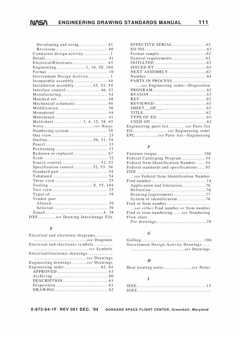
8/6/2019 Engineering Drawing Standards Manual GSFC-X-673!64!1F
http://slidepdf.com/reader/full/engineering-drawing-standards-manual-gsfc-x-673641f 123/128
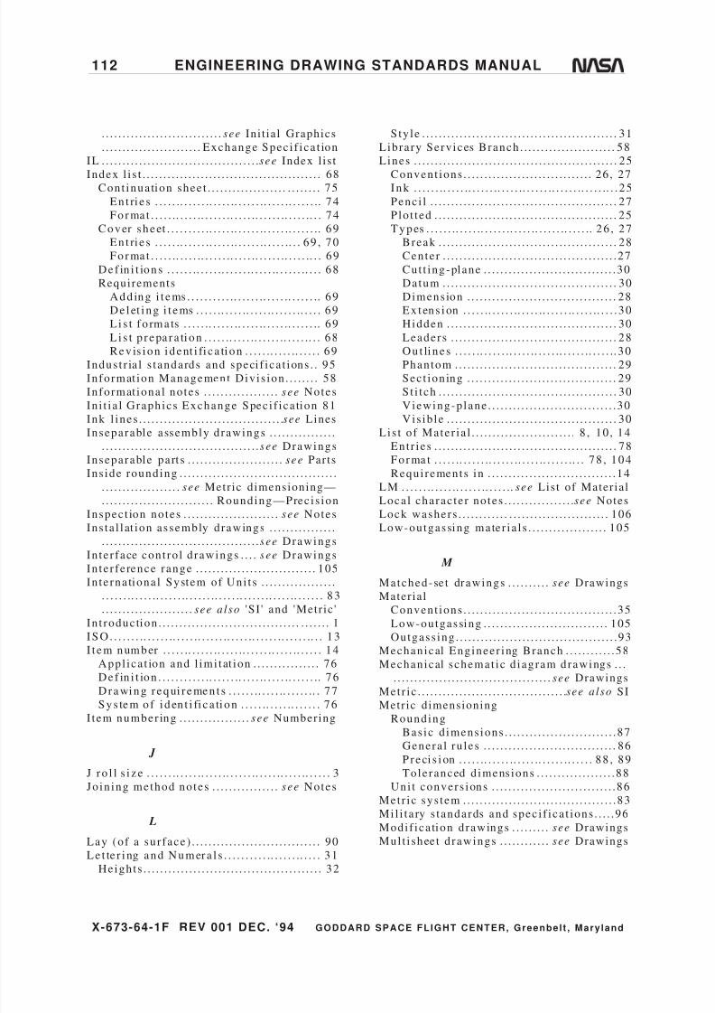
8/6/2019 Engineering Drawing Standards Manual GSFC-X-673!64!1F
http://slidepdf.com/reader/full/engineering-drawing-standards-manual-gsfc-x-673641f 124/128
X-673-64-1F REV 001 DEC. ‘94 GODDARD SPACE FLIGHT CENTER, Greenbelt , Mary land
112 ENGINEERING DRAWING STANDARDS MANUAL
. . . . . . . . . . . . . . . . . . . . . . . . . . . . . see Ini t ial Graphics
. . . . . . . . . . . . . . . . . . . . . . . . Exchange Spec i f i ca t ion
IL . . . . . . . . . . . . . . . . . . . . . . . . . . . . . . . . . . . . . . see Index l is t
Index l i s t . . . . . . . . . . . . . . . . . . . . . . . . . . . . . . . . . . . . . . . . . . . 68Cont inua tion shee t . . . . . . . . . . . . . . . . . . . . . . . . . . . 75
En t ri e s . . . . . .. . . . . . .. . . . . .. . . . . . .. . . . . .. . . . . . .. 74
For ma t . . . . . .. . . . . .. . . . . . .. . . . . .. . . . . . .. . . . . .. . . 74
Cover s heet . . . . . . . . . .. . . . . .. . . . . . .. . . . . .. . . . . . .. 69
En t ri e s . . . . . .. . . . . . .. . . . . .. . . . . . .. . . . . .. . . 69 , 70
For ma t . . . . . .. . . . . .. . . . . . .. . . . . .. . . . . . .. . . . . .. . . 69
Def in i t ions . . . . . . .. . . . . .. . . . . . .. . . . . .. . . . . . .. . . . 68
Requirements
Add ing i t ems . . . . . . . . . . .. . . . . . .. . . . . .. . . . . . .. 69
De l et i ng i t ems . . . . . .. . . . . .. . . . . .. . . . . . .. . . . . 69
Li s t f o rm a ts . . . . . .. . . . . . .. . . . . .. . . . . .. . . . . . .. 69
Li s t p r epa r a ti on . . . . . .. . . . . .. . . . . . .. . . . . .. . . 68
Rev is i on i dent i fi c a ti on . . . . . .. . . . . .. . . . . . 69Indus t r ia l s t andards and speci f i ca t ions . . 95
Informat ion Management Divi s ion . . . . . . . . 58
Informat iona l notes . . . . . . . . . . . . . . . . . . see Notes
In i t i a l Graphics Exchange Spec i f i ca tion 81
Ink l ines . . . . . . . . . . . . . . . . . . . . . . . . . . . . . . . . . . . see Lines
Inseparable assembly drawings . . . . . . . . . . . . . . . .
. . . . . . . . . . . . . . . . . . . . . . . . . . . . . . . . . . . . . . see Drawings
Inseparable part s . . . . . . . . . . . . . . . . . . . . . . . see Parts
Ins ide rounding . . . . . . . . . . . . . . . . . . . . . . . . . . . . . . . . . . . . . .
. . . . . . . . . . . . . . . . . . . see Metric dimensioning—
.. . . . . . . . . . . . . . . . . . . . . . . . . . Rounding—Prec i s ion
Inspec t ion notes . . . . . . . . . . . . . . . . . . . . . . . see Notes
Ins ta l l at ion assembly drawings . . . . . . . . . . . . . . . .. . . . . . . . . . . . . . . . . . . . . . . . . . . . . . . . . . . . . . see Drawings
In te r face cont ro l drawings . . . . see Drawings
In te r fe rence range . . . . . . . . . . . . . . . . . . . . . . . . . . . . . 105
Interna tiona l System of Uni t s . . . . . . . . . . . . . . . . . .
. . . . . . .. . . . . .. . . . . . .. . . . . . .. . . . . .. . . . . . .. . . . . .. . . . . . . 83
. . . . . . . . . . . . . . . . . . . . . . see also 'SI ' and 'Metr ic '
In t roduction . . . . . . . . . . . . . . . . . . . . . . . . . . . . . . . . . . . . . . . . . 1
I SO. . . . . . . .. . . . . . .. . . . . .. . . . . . .. . . . . .. . . . . . .. . . . . . .. . . 13
I t em num ber . . . . . .. . . . . . .. . . . . .. . . . . . .. . . . . .. . . . . . 14
Appl ica t ion and l imi tat ion . . . . . . . . . . . . . . . . 76
Def in i t ion . . . . . . . . . . . .. . . . . . .. . . . . .. . . . . .. . . . . . .. 76
Dr awi ng r equi r emen t s . . . . . . .. . . . . .. . . . . . .. . 77
Sys tem o f i den t i fi c a ti on . . . . . .. . . . . .. . . . . . . 76I tem number ing . . . . . . . . . . . . . . . . . see Numbering
J
J r o l l s i z e . . . . . . .. . . . . .. . . . . .. . . . . . .. . . . . .. . . . . .. . . . . . 3
Jo in ing method notes . . . . . . . . . . . . . . . . see Notes
L
Lay (of a sur face) . . . . . . . . . . . . . . . . . . . . . . . . . . . . . . . 90
Le t te r i ng and Num er a l s . . . . . . . . . . .. . . . . . .. . . . . 31
Heights . . . . . . . . . . . . . . . . . . . . . . . . . . . . . . . . . . . . . . . . . . . 32
Sty le . . . . . . . . . . . . . . . . . . . . . . . . . . . . . . . . . . . . . . . . . . . . . . . 31
Library Serv ices Branch. . . . . . . . . . . . . . . . . . . . . . . 58
Lines . . . . . . . . . . . . . . . . . . . . . . . . . . . . . . . . . . . . . . . . . . . . . . . . . 25
Convent ions . . . . . . . . . . . . . . . . . . . . . . . . . . . . . . . 26 , 27I nk . . . . . . .. . . . . .. . . . . . .. . . . . .. . . . . . .. . . . . . .. . . . . .. . . 25
Penci l . . . . . . . . . . . . . . . . . . . . . . . . . . . . . . . . . . . . . . . . . . . . . 27
Plo t ted . . . . . . . . . . . . . . . . . . . . . . . . . . . . . . . . . . . . . . . . . . . . 25
Types . . . . . . .. . . . . .. . . . . . .. . . . . .. . . . . . .. . . . . .. 26 , 27
Break . . . . . . . . . . . . . . . . . . . . . . . . . . . . . . . . . . . . . . . . . . . 28
Center . . . . . . . . . . . . . . . . . . . . . . . . . . . . . . . . . . . . . . . . . .27
Cut t ing-plane . . . . . . . . . . . . . . . . . . . . . . . . . . . . . . . .30
Datum .. . . . . . . . . . . . . . . . . . . . . . . . . . . . . . . . . . . . . . . . . 30
Dimens ion . . . . . . . . . . . . . . . . . . . . . . . . . . . . . . . . . . . . 28
Ex t ens i on . . . . . .. . . . . . .. . . . . .. . . . . . .. . . . . .. . . . . 30
Hidden . . . . . . . . . . . . . . . . . . . . . . . . . . . . . . . . . . . . . . . . . 30
Leaders . . . . . . . . . . . . . . . . . . . . . . . . . . . . . . . . . . . . . . . . 28
Out li ne s . . . . . .. . . . . . .. . . . . .. . . . . .. . . . . . .. . . . . .. 30Phantom . . . . . . . . . . . . . . . . . . . . . . . . . . . . . . . . . . . . . . . 29
Sec t ioning . . . . . . . . . . . . . . . . . . . . . . . . . . . . . . . . . . . . 29
St i t ch . . . . . . . . . . . . . . . . . . . . . . . . . . . . . . . . . . . . . . . . . . . 30
Viewing-plane . . . . . . . . . . . . . . . . . . . . . . . . . . . . . . .30
Vis ib le . . . . . . . . . . . . . . . . . . . . . . . . . . . . . . . . . . . . . . . . . 30
Lis t of Mater ia l . . . . . . . . . . . . . . . . . . . . . . . . . 8 , 10 , 14
Ent r ies . . . . . . . . . . . . . . . . . . . . . . . . . . . . . . . . . . . . . . . . . . . . 78
For ma t . . . . . .. . . . . . .. . . . . . .. . . . . .. . . . . . .. . . 78 , 104
Requi rements in . . . . . . . . . . . . . . . . . . . . . . . . . . . . . . .14
LM . . . . . . .. . . . . .. . . . . . .. . . . . .. see List of Mater ial
Loca l charac te r notes . . . . . . . . . . . . . . . . .see Notes
Lock washers . . . . . . . . . . . . . . . . . . . . . . . . . . . . . . . . . . . . 106
Low-outgassing mater ia l s . . . . . . . . . . . . . . . . . . . 105
M
Matched-se t drawings . . . . . . . . . . see Drawings
Mater ial
Convent ions . . . . . . . . . . . . . . . . . . . . . . . . . . . . . . . . . . . . .35
Low-outgassing . . . . . . . . . . . . . . . . . . . . . . . . . . . . . . 105
Outgass ing . . . . . . . . . . . . . . . . . . . . . . . . . . . . . . . . . . . . . . .93
Mechanical Engineer ing Branch . . . . . . . . . . . .58
Mechanical schemat ic d iagram drawings . . .
. . . . . . . . . . . . . . . . . . . . . . . . . . . . . . . . . . . . . . see Drawings
Met r ic . . . . . . . . . . . . . . . . . . . . . . . . . . . . . . . . . . . . see also SI
Metr ic dimensioningRounding
Bas ic d imens ions . . . . . . . . . . . . . . . . . . . . . . . . . . .87
Genera l ru les . . . . . . . . . . . . . . . . . . . . . . . . . . . . . . . . 86
Pr eci s i on . . . . . .. . . . . . .. . . . . .. . . . . . .. . . . . . 88 , 89
Toleranced d imens ions . . . . . . . . . . . . . . . . . . .88
Uni t convers ions . . . . . . . . . . . . . . . . . . . . . . . . . . . . . .86
Met r ic sys tem . . . . . . . . . . . . . . . . . . . . . . . . . . . . . . . . . . . . .83
Mi l i t a ry s tandards and spec i f i ca t ions . . . . .96
Modi f ica tion drawings . . . . . . . . . see Drawings
Mul t i shee t drawings . . . . . . . . . . . . see Drawings

8/6/2019 Engineering Drawing Standards Manual GSFC-X-673!64!1F
http://slidepdf.com/reader/full/engineering-drawing-standards-manual-gsfc-x-673641f 125/128
X-673-64-1F REV 001 DEC. ‘94 GODDARD SPACE FLIGHT CENTER, Greenbelt , Mary land
ENGINEERING DRAWING STANDARDS MANUAL 113
N
NAS. . . . . .. . . . . .. . . . . . .. . . . . . .. . . . . .. . . . . . .. . . . . .. . . . . 13
NASA s t anda rds and s pec i f ic a t ions . . . . . . 98
Nat iona l Bureau of Standards index . . . . . . 93NEM A. . . . . .. . . . . .. . . . . .. . . . . . .. . . . . .. . . . . . .. . . . . .. . . 13
Nomenclature . . . . . . . . . . . . . . . . . . . . . . . . . . . . . . . . . . . . . 11
Not es . . . . . .. . . . . . .. . . . . .. . . . . . .. . . . . .. . . . . . .. . . . . .. . . 25
Coa ti ng . . . . . .. . . . . . .. . . . . .. . . . . . .. . . . . .. . . . . . .. . . 18
Di mens ion . . . . . .. . . . . . .. . . . . .. . . . . . .. . . . . .. . . . . . 16
Dimens iona l to le rance . . . . . . . . . . . . . . . . . . . . . . 24
Exampl e s . . . . . . . . . . .. . . . . .. . . . . . .. . . . . .. . . . . .. . . . 16
Gener a l . . . . . .. . . . . .. . . . . . .. . . . . .. . . . . . .. . . . . .. . . . 15
Hea t t r ea t i ng . . . . . . .. . . . . .. . . . . .. . . . . . .. . . . . .. . . 17
I n f or m at i ona l . . . . . . .. . . . . .. . . . . . .. . . . . .. . . . . . .. 23
Inspec t ion . . . . . . . . . . . . . . . . . . . . . . . . . . . . . . . . . . . . . . . 20
J o i ni ng m e thod . . . . . . . . .. . . . . . .. . . . . .. . . . . . .. . . 18
Local cha r ac te r . . . . . .. . . . . .. . . . . . .. . . . . .. 15 , 23Locat i on . . . . . . . . . . . .. . . . . .. . . . . . .. . . . . .. . . . . . .. . . 15
M i sce l laneous . . . . . . .. . . . . .. . . . . .. . . . . . .. . . . . .. 21
Number ing o f . . . . . .. . . . . . .. . . . . . .. . . . . .. . . . . . .. 16
P l a ti ng . . . . . .. . . . . . .. . . . . .. . . . . . .. . . . . .. . . . . . .. . . . 18
Sur face prepara tion . . . . . . . . . . . . . . . . . . . . . . . . . . 19
Tes ti ng . . . . . . . . . . .. . . . . .. . . . . . .. . . . . .. . . . . . .. . . . . . 20
Threaded inser ts
Cl ean i ng and i n s t a ll a t ion . . . . . .. . . . . . .. . 21
War ni ng no te . . . . . . .. . . . . .. . . . . . .. . . . . .. . . . . . .. 15
NSA. . . . . .. . . . . . .. . . . . .. . . . . . .. . . . . .. . . . . . .. . . . . .. . . . . 13
NTI S . . . . . .. . . . . . .. . . . . .. . . . . . .. . . . . .. . . . . . .. . . . . . .. . . 93
Number ing . . . . . . . .. . . . . . .. . . . . .. . . . . . .. . . . . .. . . . . . . 58
F i nd . . . . . . .. . . . . .. . . . . . .. . . . . .. . . . . . .. . . . . .. . . . . . .. 60I t em . . . . . . .. . . . . .. . . . . . .. . . . . .. . . . . . .. . . . . .. . . . . . .. 60
Pa r ts . . . . . . .. . . . . .. . . . . . .. . . . . .. . . . . . .. . . . . .. . . . . . . 59
Number ing o f no t e s . . . . . .. . . . . . .. . . . . s ee No te s
O
Order of precedence. . . . . . see Specif icat ions
Or t hogr aph i c p r o jec t ion . . . . . . .. . . . . .. . . . . . .. . 25
Outgassing
Low-outgass ing mater ia l s . . . . . . . . . . . . . . . . 105
Of s pacec r af t m a te r i al s . . . . . . .. . . . . .. . . . . .. 93
Out l ine drawings . . . . . . . . . . . . . . . . . see Drawings
Outl inesI nv is i b le . . . . . .. . . . . . .. . . . . .. . . . . . .. . . . . .. . . . . . .. . 34
Vi s ib l e . . . . . .. . . . . . .. . . . . .. . . . . . .. . . . . .. . . . . . .. . . . 34
P
Par t number . . . . . . . . . . . . . . . . . . . . . . . . . . . . . . . . . . 52 , 59
Par t Pos i t ioning . . . . . . . . . . . . . . . see Posi t ioning
Parts
Dimens ions . . . . . . . . . . . . . . . . . . . . . . . . . . . . . . . . . . . . 104
Ident i f ica t ion of . . . . . . . . . . . . . . . . . . . . . . . . . . . . . 105
I ns epa r ab l e . . . . . . .. . . . . .. . . . . . .. . . . . .. . . . . . .. . . . 41
Number ing . . . . . . . . . . . . . . . . . . . . . . . . . . . . . . . . . . . . . . .59
Separable . . . . . . . . . . . . . . . . . . . . . . . . . . . . . . . . . . . . . . . . 40
Vendor . . . . . . . . . . . . . . . . . . . . . . . . . . . . . . . . . 52 , 53 , 59
Al te red . . . . . . . . . . . . . . . . . . . . . . . . . . . . . . . . . . . 39 , 59Se l ec t ed . . . . . . .. . . . . .. . . . . .. . . . . . .. . . . . .. 39 , 59
Weldment . . . . . . . . . . . . . . . . . . . . . . . . . . . . . . . . . . . . . . 104
Pa r ts l i s t . . . . . .. . . . . . .. . . . . .. . . . . .. . . . . . .. . . . . . 14 , 68
Cont inua t ion shee t . . . . . . . . . . . . . . . . . . . . . . . . . . . . 73
Ent r ies . . . . . . . . . . . . . . . . . . . . . . . . . . . . . . . . . . . . . . . . . 72
For ma t . . . . . .. . . . . . .. . . . . .. . . . . . .. . . . . .. . . . . . .. . 72
Supplementary heading l i s t . . . . . . . . . . . . . 73
Cover sheet
En t ri e s . . . . . .. . . . . . .. . . . . .. . . . . . .. . . . . .. . . 69 , 70
For ma t . . . . . . .. . . . . .. . . . . . .. . . . . .. . . . . . .. . . . . .. . 69
Def in i t ions . . . . . . . . . . . . . . . . . . . . . . . . . . . . . . . . . . . . . . 68
Engineer ing . . . . . . . . . . . . . . . . . . . . . . . . . . 59 , 60 , 80
Prefer red . . . . . . . . . . . . . . . . . . . . . . . . . . . . . . . . . . . . . . . . . 14Requirements
Adding i t ems . . . . . . . . . . . . . . . . . . . . . . . . . . . . . . . . .69
Dele t ing it ems . . . . . . . . . . . . . . . . . . . . . . . . . . . . . . . 69
Lis t formats . . . . . . . . . . . . . . . . . . . . . . . . . . . . . . . . . . 69
Lis t prepara t ion . . . . . . . . . . . . . . . . . . . . . . . . . . . . . 68
Revis ion identi f i ca t ion . . . . . . . . . . . . . . . . . . .69
Penci l d r awi ngs . . . . . .. . . . . . .. . . . . see Drawings
Penci l l ines . . . . . . . . . . . . . . . . . . . . . . . . . . . . . . see Lines
Pic tur iza t ion . . . . . . . . . . . . . . . . . . . . . . . . . . . . . . . . . . . . . . .33
PL . . . . . . . . . . . . . . . . . . . . . . . . . . . . . . . . . . . . . . see Parts l is t
P la t ing notes . . . . . . . . . . . . . . . . . . . . . . . . . . . . .see Notes
Plo t ted l ines . . . . . . . . . . . . . . . . . . . . . . . . . . . . . see Lines
Pos i t ioning . . . . . . . . . . . . . . . . . . . . . . . . . . . . . . . . . . . 33 , 35Prec i s ion rounding . . . . . . . . . . . . . . . . . . . . . . . . . . . . . . . . .
. . . . . . see Metric dimensioning—Rounding
Press f i t s . . . . . . . . . . . . . . . . . . . . . . . . . . . . . . . . . . . . . . . . . . 105
Projec ted to le rance zone . . . . . . . . . . . . . . . . . . . . 106
Projec ted v iews . . . . . . . . . . . . . . . . . . . . . . . . see Views
R
Rad ii . . . . . .. . . . . . .. . . . . .. . . . . . .. . . . . . .. . . . . .. . . . . . .. 105
Regardless of Fea ture Size . . . . . . . . . . . . . . . . . 105
Revis ion b lock . . . . . . . . . . . . . . . . . . . . . . . . . . . . 4 , 9 , 65
APPROVAL . . . . . . .. . . . . .. . . . . . .. . . . . .. . . . . . .. . . . . 9
DATE . . . . . .. . . . . . .. . . . . .. . . . . . .. . . . . .. . . . . . .. . . . . . . 9DESCRIPTION.. . . . . . . . . . . . . . . . . . . . . . . . . . . . . . . . . 9
Samples . . . . . . . . . . . . . . . . . . . . . . . . . . . . . . . . . . . . . . . 5 , 66
SYM . . . . . . .. . . . . . .. . . . . .. . . . . . .. . . . . .. . . . . . .. . . . . .. . 9
ZONE . . . . . .. . . . . . .. . . . . .. . . . . . .. . . . . .. . . . . . .. . . . . . . 9
Revis ions . . . . . . . . . . . . . . . . . . . . . . . . . . . . . . . . . . . . . . . . . . . 65
Ident i f ica t ion . . . . . . . . . . . . . . . . . . . . . . . . . . . . . . . . . . .65
Methods . . . . . . . . . . . . . . . . . . . . . . . . . . . . . . . . . . . . . . . . . . 65
Mul t i shee t drawings . . . . . . . . . . . . . . . . . . . . . . . . .65
Recording . . . . . . . . . . . . . . . . . . . . . . . . . . . . . . . . . . . . . . . .65
Redrawn or rep laced drawings . . . . . . . . . . .67
Rota ted v iews . . . . . . . . . . . . . . . . . . . . . . . . . . see Views
Roundi ng . . . . . .. . . . . . .. . . . . . .. . . . . .. . . . . . .. . . . . .. . . . 86

8/6/2019 Engineering Drawing Standards Manual GSFC-X-673!64!1F
http://slidepdf.com/reader/full/engineering-drawing-standards-manual-gsfc-x-673641f 126/128
X-673-64-1F REV 001 DEC. ‘94 GODDARD SPACE FLIGHT CENTER, Greenbelt , Mary land
114 ENGINEERING DRAWING STANDARDS MANUAL
Rounding: . . . . see also Metric dimensioning
S
SAE . . . . . .. . . . . . .. . . . . .. . . . . . .. . . . . .. . . . . . .. . . . . . .. . . . 13
Sca le . . . . . . . . . . . . . . . . . . . . . . . . . . . . . . . . . . . . . . . . . . . . . . . . . 32
Sec ti ons . . . . . .. . . . . . .. . . . . .. . . . . . .. . . . . .. . . . . . .. . . . . 34
I dent i f ic a t ion . . . . . . .. . . . . .. . . . . .. . . . . . .. . . . . .. . 37
Locat i ng . . . . . . . . . . . .. . . . . .. . . . . . .. . . . . .. . . . . . .. . . 38
Secur i ty c lass i fi ca t ion . . . . . . . . . . . . . . . . . . . 10 , 15
Se l ec t ed pa r ts . . . . . .. . . . . .. . see Parts—Vendor
Selec ted vendor par t drawings . . . . . . . . . . . . . . . . .
. . . . . . . . . . . . . . . . . . . . . . . . . . . . . . . . . . . . . . see Drawings
Separable par t s . . . . . . . . . . . . . . . . . . . . . . . . . see Parts
Shee t number ing . . . . . . . . . . . . . . . . . . . . . . . . . . . . . . . . . . . 3
S I . .. s ee a ls o Internat ional System of Units
Un i ts and s ymbo l s . . . . . . .. . . . . .. . . . . .. . . . . . .. 83Si lver -p la ted hardware . . . . . . . . . . . . . . . . . . . . . . . 106
Solder ing . . . . . . . . . . . . . . . . . . . . . . . . . . . . . . . . . . . . . . 18 , 89
Source cont ro l drawings . . . . . . . see Drawings
Space Tr ans po rt a t ion Sys t em . . . . . .. . . . . .. . . 20
Speci f ic a t ion ca l lou t s . . . . . .. . . . . . .. . . . . .. . . . . . 24
Speci f i cat ion cont ro l drawings . . . . . . . . . . . . . . . . .
. . . . . . . . . . . . . . . . . . . . . . . . . . . . . . . . . . . . . . see Drawings
Speci f ic a t ions . . . . . .. . . . . . .. . . . . .. . . . . .. . . . . . .. . . . 82
Order of precedence . . . . . . . . . . . . . . . . . . . . . . . . . 60
Subsequen t changes . . . . . .. . . . . . .. . . . . . .. . . . . 24
Thread . . . . . . . . . . . . . . . . . . . . . . . . . . . . . . . . . . . . . . . 91 , 92
Speci f i cat ions index . . . . . . . . . . . . . . . . . . . . . . . . . . . . . . .
. . see Standards and specif icat ions indexStandard part drawing . . . . . . . . . . see Drawings
S t anda r ds . . . . . .. . . . . .. . . . . . .. . . . . . .. . . . . .. . . . . . .. . . 82
Order of precedence . . . . . . . . . . . . . . . . . . . . . . . . . 60
Standards and spec i f ica t ions index . . . . . . . 93
Feder a l . . . . . . . . .. . . . . . .. . . . . .. . . . . . .. . . . . .. . . . . . .. 93
Indus t r ia l . . . . . . . . . . . . . . . . . . . . . . . . . . . . . . . . . . . . . . . . 95
M i li t a ry . . . . . .. . . . . .. . . . . . .. . . . . .. . . . . .. . . . . . .. . . . 96
NASA . . . . . . .. . . . . .. . . . . . .. . . . . .. . . . . . .. . . . . .. . . . . 98
Nat iona l Bureau of Standards . . . . . . . . . . . . 93
Standards and specif icat ions numerical
i ndex . . . . . . . .. . . . . .. . . . . . .. . . . . .. . . . . . .. . . . . .. . . . . . 98
S TS . .. .. .. see Space Transportat ion System
Support ing documentat ionNumber ing . . . . . .. . . . . . .. . . . . .. . . . . . .. . . . . . .. . . . . 58
Sur face prepara t ion notes . . . . . . . . . . see Notes
Surface roughness
Con tr o l o f . . . . . . . .. . . . . . .. . . . . .. . . . . . .. . . . . .. . . . . 90
Sur face t ex ture . . . . . . . . . . . . . . . . . . . . . . . . . . . . . . . . . . . 90
Standards . . . . . . . . . . . . . . . . . . . . . . . . . . . . . . . . . . . . . . . . 90
Symbo l s . . . . . .. . . . . . .. . . . . .. . . . . . .. . . . . .. . . . . . .. . 90
Symbols
Cr oss - hat ch ing . . . . . .. . . . . . .. . . . . .. . . . . . .. . . . . . 35
El ect r ic a l /E l ect r on i c . . . . . .. . . . . .. . . . . .. . . . . . 43
Welding . . . . . . . . . . . . . . . . . . . . . . . . . . . . . . . . . . . . . . . . . . 92
Wir ing . . . . . . . . . . . . . . . . . . . . . . . . . . . . . . . . . . . . . . . . . . . . 43
T
Tabula ted drawings . . . . . . . . . . . . . see Drawings
Templa tes . . . . . . . . . . . . . . . . . . . . . . . . . . . . . . 55 , 82 , 104
Tes t ing notes . . . . . . . . . . . . . . . . . . . . . . . . . . . . see NotesThi rd-angle or thographic projec t ion . . . . . .25
Thread spec i f i ca t ions . . . . . . . . . . . . . . . . . . . . . 91 , 92
Threaded inser ts—Cleaning and
ins ta l l at ion notes . . . . . . . . . . . . . . . . . . . .see Notes
T i t le b l ock . . . . . . .. . . . . .. . . . . . .. . . . . .. . 4 , 9 , 32 , 33
APPROVED . . . . . .. . . . . .. . . . . . .. . . . . . .. . . . . .. . . . . . 7
CHECKED. . . . . . . . . . . .. . . . . .. . . . . . .. . . . . .. . . . . . .. . 7
CODE . . . . . .. . . . . . .. . . . . .. . . . . . .. . . . . .. . . . . . .. . . . . .. 7
DATE . . . . . .. . . . . . .. . . . . .. . . . . . .. . . . . .. . . . . . .. . . . . . . 7
DESCRIPTION.. . . . . . . . . . . . . . . . . . . . . . . . . . . . . . . . . 9
DESI GNER. . . . . . . . . . .. . . . . . .. . . . . .. . . . . . .. . . . . .. . 7
Dr awing No . . . . . . . .. . . . . .. . . . . . .. . . . . . .. . . . . .. . . . 7
DRAWN . . . . . . .. . . . . .. . . . . . .. . . . . .. . . . . . .. . . . . .. . . . 7EXAM INATI ON . . . . . .. . . . . . .. . . . . .. . . . . . .. . . . . . 8
FLI GHT HARDWARE. . . . . . .. . . . . . .. . . . . .. . . . 8
HARDNESS TESTI NG . . . . . .. . . . . . .. . . . . .. . . . 8
I TEM NO. . . . . . .. . . . . .. . . . . . .. . . . . .. . . . . . .. . . . . . .. 8
M ATERI AL . . . . . .. . . . . . .. . . . . .. . . . . . .. . . . . .. . . . . . 9
M ATERI AL SPEC. . . . . . .. . . . . . .. . . . . .. . . . . .. . . 9
M ETRIC. . . . . . . . . . .. . . . . . .. . . . . .. . . . . . .. . . . . .. . . . . . 8
NEXT ASSY . . . . . . .. . . . . .. . . . . . .. . . . . .. . . . . . .. . . . 8
PART NO. . . . . . . .. . . . . .. . . . . . .. . . . . .. . . . . . .. . . . . .. 8
REQD . . . . . .. . . . . . .. . . . . .. . . . . . .. . . . . .. . . . . . .. . . . . .. 8
Sampl e . . . . . . .. . . . . .. . . . . .. . . . . . .. . . . . .. . . . . . .. . . . . . 5
SCALE. . . . . . .. . . . . .. . . . . . .. . . . . .. . . . . . .. . . . . .. . . . . . 7
SH___OF___ . . . . . . . . . . . . . . . . . . . . . . . . . . . . . . . . . . . . . . 7Sof twa r e u s ed . . . . . .. . . . . . .. . . . . .. . . . . . .. . . . . .. . . 8
TI TLE. . . . . . . . .. . . . . .. . . . . .. . . . . . .. . . . . .. . . . . . .. . . . . 7
USED ON . . . . . . .. . . . . .. . . . . . .. . . . . .. . . . . . .. . . . . .. . 7
WT . . . . . . .. . . . . . .. . . . . .. . . . . . .. . . . . .. . . . . . .. . . . . .. . . . 7
Tolerance Block
Met r ic . . . . . . . . . . . . . . . . . . . . . . . . . . . . . . . . . . . . . . . . . . . . . 86
Tolerances . . . . . . . . . . . . . . . . . . 24 , 82 , 84 , 88 , 104
Loose . . . . . . . . . . . . . . . . . . . . . . . . . . . . . . . . . . . . . . . . . . . . 105
Met r ic . . . . . . . . . . . . . . . . . . . . . . . . . . . . . . . . . . . . . . . . . . . . . 86
Tolerancing
True pos i t ion . . . . . . . . . . . . . . . . . . . . . . . . . . . . . . . . . 105
Tool ing drawings . . . . . . . . . . . . . . . . see Drawings
Tool ing f ix tures . . . . . . . . . . . . . . . . . . . . . . . . . . . . . . . . . . 55Transpor ted v iews . . . . . . . . . . . . . . . . . . . . see Views
True pos i tion d imens ioning . . . . . . . . . . . . . . . . . . . . .
. . . . . . . . . . . . . . . . . . . . . . . . . . . . . . . . see Dimensioning
U
Uni t number princ ip le . . . . . . . . . . . . . . . . . . . . . . . . . . 58
Uni t rounding . . . . . . . . . . . . . . . . . . . . . see Rounding
8/6/2019 Engineering Drawing Standards Manual GSFC-X-673!64!1F
http://slidepdf.com/reader/full/engineering-drawing-standards-manual-gsfc-x-673641f 127/128
X-673-64-1F REV 001 DEC. ‘94 GODDARD SPACE FLIGHT CENTER, Greenbelt , Mary land
ENGINEERING DRAWING STANDARDS MANUAL 115
V
Vapor deg r eas i ng . . . . . . .. . . . . .. . . . . . .. . . . . . .. . . . 20
Vendor par t . . . . . . . . . . . . . . . . . . . . . . . . . . . . . . see Parts
Vendor par t drawings . . . . . . . . . . . see DrawingsVi ews . . . . . . .. . . . . .. . . . . . .. . . . . .. . . . . . .. . . . . . .. . 25 , 36
I dent i f ic a t ion . . . . . . .. . . . . .. . . . . .. . . . . . .. . . . . .. . 37
Locat i ng . . . . . . . . . . . .. . . . . .. . . . . . .. . . . . .. . . . . . .. . . 38
Pr o jec t ed . . . . . .. . . . . . .. . . . . .. . . . . . .. . . . . .. . . . . . .. 36
Rota ted . . . . . . . . . . . . . . . . . . . . . . . . . . . . . . . . . . . . . . . . . . . 36
Sec ti onal . . . . . . .. . . . . .. . . . . .. . . . . . .. . . . . .. . . . . . .. 34
Des igna ti on . . . . . .. . . . . .. . . . . . .. . . . . .. . . . . . .. . 35
Pos it i oni ng . . . . . .. . . . . . .. . . . . .. . . . . .. . . . . . .. . 35
Tr ans port ed . . . . . .. . . . . . .. . . . . .. . . . . . .. . . . . .. . . . 36
W
Waviness (of a sur face) . . . . . . . . . . . . . . . . . . . . . . . 90Wel di ng . . . . . .. . . . . .. . . . . . .. . . . . .. . . . . . .. . . . . . .. . . . . 18
Gener a l . . . . . .. . . . . . .. . . . . .. . . . . . .. . . . . .. . . . . . .. . . 92
Not es . . . . . . .. . . . . .. . . . . . .. . . . . .. . . . . . .. . . . . .. . . . . . 18
Speci f i ca t ion ca l lout s . . . . . . . . . . . . . . . . . . . . . . . 92
Symbo l s . . . . . .. . . . . .. . . . . . .. . see also Symbols
Locat i on s i gni f ic ance . . . . . . .. . . . . .. . . . . .. 92
Weldments . . . . . . . . . . . . . . . . . . . . . . . . . . . . . . . . . . 44 , 104
Wir ing symbols . . . . . . . . . . . . . . . . . . . . see Symbols
Z
Zoning . . . . . . . . . . . . . . . . . . . . . . . . . . . . . . . . . . . . . . . . . . . 4 , 10

8/6/2019 Engineering Drawing Standards Manual GSFC-X-673!64!1F
http://slidepdf.com/reader/full/engineering-drawing-standards-manual-gsfc-x-673641f 128/128
116 ENGINEERING DRAWING STANDARDS MANUAL