Embed Size (px)
Citation preview


Engineering Materials
For further volumes:http://www.springer.com/series/4288

Hans Berns • Valentin GavriljukSascha Riedner
High Interstitial StainlessAustenitic Steels
123
Hans BernsRuhr-UniversityBochumGermany
Valentin GavriljukG.V. Kurdyumov Institute for Metal
PhysicsKievUkraine
Sascha RiednerDeutsche Edelstahlwerke GmbHKamenGermany
ISSN 1612-1317 ISSN 1868-1212 (electronic)ISBN 978-3-642-33700-0 ISBN 978-3-642-33701-7 (eBook)DOI 10.1007/978-3-642-33701-7Springer Heidelberg New York Dordrecht London
Library of Congress Control Number: 2012949081
� Springer-Verlag Berlin Heidelberg 2013This work is subject to copyright. All rights are reserved by the Publisher, whether the whole or part ofthe material is concerned, specifically the rights of translation, reprinting, reuse of illustrations,recitation, broadcasting, reproduction on microfilms or in any other physical way, and transmission orinformation storage and retrieval, electronic adaptation, computer software, or by similar or dissimilarmethodology now known or hereafter developed. Exempted from this legal reservation are briefexcerpts in connection with reviews or scholarly analysis or material supplied specifically for thepurpose of being entered and executed on a computer system, for exclusive use by the purchaser ofthe work. Duplication of this publication or parts thereof is permitted only under the provisionsof the Copyright Law of the Publisher’s location, in its current version, and permission for use mustalways be obtained from Springer. Permissions for use may be obtained through RightsLink at theCopyright Clearance Center. Violations are liable to prosecution under the respective Copyright Law.The use of general descriptive names, registered names, trademarks, service marks, etc. in thispublication does not imply, even in the absence of a specific statement, that such names are exemptfrom the relevant protective laws and regulations and therefore free for general use.While the advice and information in this book are believed to be true and accurate at the date ofpublication, neither the authors nor the editors nor the publisher can accept any legal responsibility forany errors or omissions that may be made. The publisher makes no warranty, express or implied, withrespect to the material contained herein.
Printed on acid-free paper
Springer is part of Springer Science+Business Media (www.springer.com)
Preface
A close cooperation between the Institute of Metal Physics in Kiev, Ukraine, andthe Chair of Materials Technology at the Ruhr University Bochum, Germany, hasbeen going on now for more than 20 years. During the first decade the joint effortcentered on high nitrogen steels (HNS) and the partners published a book on thissubject in 1999. Already then they had shown that combined alloying ofmartensitic stainless steels with carbon + nitrogen considerably improved structureand properties. These findings were transferred to the hardenable stainless bearingsteel CRONIDUR� used, e.g., in aviation and to SolNit� which allows casehardening of stainless steel with nitrogen instead of carbon.
The second decade of partnership was dedicated to extending the beneficialC+N concept to new stainless austenitic grades called high interstitial steels (HIS).The results compiled in the present book have two major targets. On the scientificside the structure/ property relation starts at the electron structure and is carried onto the macroscale explaining the superior performance of HIS. The engineeringaspects cover major steps of industrial manufacture and possible applications.Compared to similar HNS the new HIS do without costly pressure or powdermetallurgy. Thus the contents are of interest to materials scientists working inR&D but also to engineers in design, manufacture, and materials selection.
The authors thank Prof. Dr. Bela Shanina (Theoretic Physics), Dr. habil. YuriPetrov (Electron Microscopy), Dr. Andrij Tyshchenko (Mössbauer Spectroscopy)in Kiev and Dr.-Ing. Fabian Schmalt, Dr.-Ing. Lais Mujica-Roncery, and Dipl.Ing. Nilofar Nabiran in Bochum for their most valuable contributions. Thanksare also extended to other researchers, students, and technical staff involved inthe development of HIS and to Miriam Rockenbach, Agnes Krolik, and Dipl.Ing. Fabian Pöhl for preparing the final manuscript. The authors are grateful toProf. Dr.-Ing. Werner Theisen, Head of Chair in Bochum, for his continuoussupport to the HIS project and to the German research foundation (DFG) for
v

sponsoring part of the work. They feel also indebted to the National Academy ofScience and the Science and Technology Center in Ukraine for financial support.Last but not least, we thank several companies for melting and processing newHIS (see Chap. 5).
Summer 2012 Hans BernsValentin Gavriljuk
Sascha Riedner
vi Preface
Contents
1 Introduction . . . . . . . . . . . . . . . . . . . . . . . . . . . . . . . . . . . . . . . . 11.1 High Nitrogen Steels . . . . . . . . . . . . . . . . . . . . . . . . . . . . . . . 11.2 High Interstitial Steels . . . . . . . . . . . . . . . . . . . . . . . . . . . . . . 21.3 Aim . . . . . . . . . . . . . . . . . . . . . . . . . . . . . . . . . . . . . . . . . . . 31.4 Procedure . . . . . . . . . . . . . . . . . . . . . . . . . . . . . . . . . . . . . . . 4References . . . . . . . . . . . . . . . . . . . . . . . . . . . . . . . . . . . . . . . . . . 5
2 Constitution . . . . . . . . . . . . . . . . . . . . . . . . . . . . . . . . . . . . . . . . . 72.1 General Remarks . . . . . . . . . . . . . . . . . . . . . . . . . . . . . . . . . . 72.2 Variation of Interstitial Content . . . . . . . . . . . . . . . . . . . . . . . . 82.3 Effect of C/N Ratio . . . . . . . . . . . . . . . . . . . . . . . . . . . . . . . . 92.4 Variation of Substitutional Content . . . . . . . . . . . . . . . . . . . . . 11
2.4.1 Chromium and Manganese . . . . . . . . . . . . . . . . . . . . . . 112.4.2 Molybdenum and Copper. . . . . . . . . . . . . . . . . . . . . . . 142.4.3 Tramp Elements . . . . . . . . . . . . . . . . . . . . . . . . . . . . . 16
2.5 Selection of Steels . . . . . . . . . . . . . . . . . . . . . . . . . . . . . . . . . 17References . . . . . . . . . . . . . . . . . . . . . . . . . . . . . . . . . . . . . . . . . . 19
3 Structure . . . . . . . . . . . . . . . . . . . . . . . . . . . . . . . . . . . . . . . . . . . 213.1 As-Quenched . . . . . . . . . . . . . . . . . . . . . . . . . . . . . . . . . . . . 22
3.1.1 Electron Structure: Calculated and Measured . . . . . . . . . 223.1.2 Atomic Distribution. . . . . . . . . . . . . . . . . . . . . . . . . . . 283.1.3 Chemical Nanoscale Homogeneity . . . . . . . . . . . . . . . . 36
3.2 Structural Change by Loading. . . . . . . . . . . . . . . . . . . . . . . . . 473.2.1 Tensile Straining. . . . . . . . . . . . . . . . . . . . . . . . . . . . . 473.2.2 Effect of Subzero Temperature . . . . . . . . . . . . . . . . . . . 593.2.3 Effect of Strain Rate . . . . . . . . . . . . . . . . . . . . . . . . . . 613.2.4 Effect of Cyclic Loading . . . . . . . . . . . . . . . . . . . . . . . 68
References . . . . . . . . . . . . . . . . . . . . . . . . . . . . . . . . . . . . . . . . . . 77
vii

4 Properties . . . . . . . . . . . . . . . . . . . . . . . . . . . . . . . . . . . . . . . . . . 854.1 Mechanical Properties . . . . . . . . . . . . . . . . . . . . . . . . . . . . . . 85
4.1.1 Tensile Properties at Room Temperature . . . . . . . . . . . . 854.1.2 Tensile Properties at Subzero Temperatures . . . . . . . . . . 884.1.3 Tensile Properties at Elevated Temperatures. . . . . . . . . . 884.1.4 Creep Properties . . . . . . . . . . . . . . . . . . . . . . . . . . . . . 914.1.5 Hardness . . . . . . . . . . . . . . . . . . . . . . . . . . . . . . . . . . 934.1.6 Notch Impact Toughness . . . . . . . . . . . . . . . . . . . . . . . 934.1.7 Rotating Bending Fatigue. . . . . . . . . . . . . . . . . . . . . . . 94
4.2 Wear Resistance . . . . . . . . . . . . . . . . . . . . . . . . . . . . . . . . . . 954.2.1 Abrasive Wear . . . . . . . . . . . . . . . . . . . . . . . . . . . . . . 964.2.2 Impact Wear. . . . . . . . . . . . . . . . . . . . . . . . . . . . . . . . 964.2.3 Wear by Cavitation . . . . . . . . . . . . . . . . . . . . . . . . . . . 99
4.3 Corrosion Resistance . . . . . . . . . . . . . . . . . . . . . . . . . . . . . . . 994.3.1 Submersion Tests . . . . . . . . . . . . . . . . . . . . . . . . . . . . 1004.3.2 Current Density/Potential Tests. . . . . . . . . . . . . . . . . . . 1024.3.3 Tests on Intercrystalline Corrosion . . . . . . . . . . . . . . . . 106
4.4 Magnetic Properties . . . . . . . . . . . . . . . . . . . . . . . . . . . . . . . . 106References . . . . . . . . . . . . . . . . . . . . . . . . . . . . . . . . . . . . . . . . . . 108
5 Manufacture . . . . . . . . . . . . . . . . . . . . . . . . . . . . . . . . . . . . . . . . 1115.1 Melting and Casting. . . . . . . . . . . . . . . . . . . . . . . . . . . . . . . . 112
5.1.1 Ingots . . . . . . . . . . . . . . . . . . . . . . . . . . . . . . . . . . . . 1125.1.2 Centrifugal Castings . . . . . . . . . . . . . . . . . . . . . . . . . . 1135.1.3 Sand Castings . . . . . . . . . . . . . . . . . . . . . . . . . . . . . . . 1135.1.4 Refractories . . . . . . . . . . . . . . . . . . . . . . . . . . . . . . . . 114
5.2 Hot Working. . . . . . . . . . . . . . . . . . . . . . . . . . . . . . . . . . . . . 1155.3 Heat Treatment . . . . . . . . . . . . . . . . . . . . . . . . . . . . . . . . . . . 116
5.3.1 Solution Annealing . . . . . . . . . . . . . . . . . . . . . . . . . . . 1165.3.2 Interrupted Quenching . . . . . . . . . . . . . . . . . . . . . . . . . 1185.3.3 Continuous Quenching. . . . . . . . . . . . . . . . . . . . . . . . . 1205.3.4 Aging . . . . . . . . . . . . . . . . . . . . . . . . . . . . . . . . . . . . 123
5.4 Cold Drawing . . . . . . . . . . . . . . . . . . . . . . . . . . . . . . . . . . . . 1235.5 Welding . . . . . . . . . . . . . . . . . . . . . . . . . . . . . . . . . . . . . . . . 1245.6 Machining . . . . . . . . . . . . . . . . . . . . . . . . . . . . . . . . . . . . . . 125References . . . . . . . . . . . . . . . . . . . . . . . . . . . . . . . . . . . . . . . . . . 126
6 Assessment . . . . . . . . . . . . . . . . . . . . . . . . . . . . . . . . . . . . . . . . . 1276.1 From Structure to Properties . . . . . . . . . . . . . . . . . . . . . . . . . . 127
6.1.1 Mechanical Properties . . . . . . . . . . . . . . . . . . . . . . . . . 1286.1.2 Wear Behaviour . . . . . . . . . . . . . . . . . . . . . . . . . . . . . 1306.1.3 Corrosion Resistance . . . . . . . . . . . . . . . . . . . . . . . . . . 1306.1.4 Nonmagnetic State . . . . . . . . . . . . . . . . . . . . . . . . . . . 131
viii Contents
6.2 From Manufacture to Application . . . . . . . . . . . . . . . . . . . . . . 1316.2.1 Constitution and Hot Manufacture. . . . . . . . . . . . . . . . . 1326.2.2 Workhardening and Cold Manufacture . . . . . . . . . . . . . 1336.2.3 Application . . . . . . . . . . . . . . . . . . . . . . . . . . . . . . . . 134
6.3 Pros and Cons of HIS . . . . . . . . . . . . . . . . . . . . . . . . . . . . . . 1376.3.1 Pros. . . . . . . . . . . . . . . . . . . . . . . . . . . . . . . . . . . . . . 1376.3.2 Cons . . . . . . . . . . . . . . . . . . . . . . . . . . . . . . . . . . . . . 138
References . . . . . . . . . . . . . . . . . . . . . . . . . . . . . . . . . . . . . . . . . . 138
Appendix A: Tables. . . . . . . . . . . . . . . . . . . . . . . . . . . . . . . . . . . . . . 141
Appendix B: Figures . . . . . . . . . . . . . . . . . . . . . . . . . . . . . . . . . . . . . 151
About the Authors. . . . . . . . . . . . . . . . . . . . . . . . . . . . . . . . . . . . . . . 163
Index . . . . . . . . . . . . . . . . . . . . . . . . . . . . . . . . . . . . . . . . . . . . . . . . 165
Contents ix

Chapter 1Introduction
Standard stainless austenitic CrNi (Mo) steels are used in a wide range ofapplications because of their high corrosion resistance and ductility. Their lowinterstitial content enhances weldability but lowers the yield strength. In contrastto sheet material, castings and forgings do not as much rely on weldability butwould profit from more strength. In these cases solid solution strengthening byinterstitial atoms of carbon and nitrogen is a promising way of raising strengthwithout losing too much ductility. However, the solubility of interstitial elementsdepends on the concentration of substitutional elements as e.g. chromium, nickel,manganese and molybdenum. Of these, Cr and Mo are required for corrosionresistance, Ni and Mn for austenite stability. Therefore a proper balance of sub-stitutional elements has to be established to enhance the concentration of inter-stitials and thus the strength of austenitic steels. In principle one may use C or N orC ? N but C alone did not meet the requirements.
1.1 High Nitrogen Steels
Chromium reduces the activity of carbon in steel thus increasing its solubility.However, the maximum solubility at the border to carbide precipitation, i.e. therange of homogeneous austenite, is reduced. Nickel enhances the activity ofcarbon and lowers its solubility in the lattice. The effect of chromium and nickelon interstitial nitrogen is similar to that on interstitial carbon, except for a highersolubility of the former. In contrast, volatile nitrogen escapes from the melt as N2
gas. This situation is expressed by a solubility of N [ C in austenite but N \\ Cin the melt and comprises the basic dilemma of stainless high nitrogen steels(HNS) [1]: Nitrogen offers more solubility in austenite and therefore more strengthbut requires special manufacturing routes to introduce high contents to the steel.Of these melting and solidification under N2 pressure (pressure metallurgy) and
H. Berns et al., High Interstitial Stainless Austenitic Steels,Engineering Materials, DOI: 10.1007/978-3-642-33701-7_1,� Springer-Verlag Berlin Heidelberg 2013
1
solid state nitriding of steel powder followed by hot compaction (powder metal-lurgy) have been industrially exploited. But compared to standard ingot metallurgyat normal pressure of air, pressure and powder metallurgy considerably increasethe costs.
Instead of special manufacturing processes suitable alloying may be used toenhance the nitrogen solubility of the melt. It aims at an exchange of nickel bymanganese, because the latter raises the nitrogen solubility in contrast to theformer. About twice as much manganese as nickel is required to fend off d-ferritewhich is expressed e.g. by the Schaeffler diagram [2]. Steel Cr18Mn18N0.55(in mass %) is e.g. used for retaining rings on electric generator shafts, steelMn23Cr21Ni2N0.85 for drill collars. The 0.2 % proof strength of these two HNSgrades, molten at normal pressure of air, was raised to about 400 and 600 MPa,respectively, which amounts to two or three times the level encountered in stan-dard steel Cr18Ni10. The increase from 0.55 to 0.85 mass % N in these two HNSis brought about by a higher content of the substitutional elements chromium andmanganese which spur the nitrogen solubility. However, the fracture elongation intensile tests is lowered and the ductile to brittle transition temperature (DBTT) innotch impact tests is raised pointing to some embrittlement.
1.2 High Interstitial Steels
To avoid this deficiency it was proposed to saturate a lean austenitic CrMn steelwith interstitial nitrogen at normal pressure and add interstitial carbon to furtherraise the strength. This concept of high interstitial steels (HIS) with C ? N waspresented in 2002 [3] and steel Mn17Cr15N0.43C0.39 showed the followingmechanical properties: proof strength Rp0.2 = 494 MPa, true fracture strengthR = 2635 MPa, elongation A = 78 % [4, 5]. This remarkable combination ofstrength and ductility was explained by an increase in the concentration ne of freeelectrons in austenite via combined alloying with C ? N, compared to alloyingwith C or N alone. A high ne enhances the ductile metallic character of interatomicbonding. From previous work on the austenite of martensitic stainless steel it wasalready known [1, 6] that—in the order of alloying with C, N or C ? N—shortrange atomic ordering is promoted which stabilizes the austenitic phase and raisesthe interstitial solubility. The significance of the C/N ratio for the precipitation ofM2N nitrides or M23C6 carbides and for welding of austenitic CrMn steels wasmentioned in [3].
The stepwise addition of up to 0.4 mass % C to steels with (mass %) 19Mn,17Cr, 3Ni and 0.4–0.55 N raised strength and ductility but hardly the DBTT [7–9].The corrosion resistance was improved as well, in that the passivation and re-passivation was enhanced and the resistance to pitting corrosion strengthened.These beneficial effects assigned to carbon may have been based on C ? N,
2 1 Introduction
though. It was pointed out that the temperature of beginning precipitationincreased with the carbon content leading to embrittlement at lower temperatures.The strengthening part of this precipitation was used in steels for exhaust valves,as e.g. Cr21Mn9Ni4C0.53N0.42 which came into use already in 1952 [10]. Theyare probably the earliest HIS, but were not meant to dwell on homogenousaustenite.
A most recent development started from high manganese TWIP steels whichrely on twinning induced plasticity [11]. Chromium was added to provide amoderate corrosion resistance and C ? N to enhance the strength. SteelMn25Cr12C0.32N0.45 for instance arrived at Rp 0.2 = 443 MPa, R = 1635 MPaand A = 99.7 % [12, 13]. This unique combination of strength and high ductilityresulted in a specific fracture energy Ws = 751 J/cm3 which is probably thehighest ever measured at room temperature [14]. At a stacking fault energy (SFE)of 31 mJ/cm3 twinning is the major strengthening mechanism. The carbide/nitrideprecipitation was studied in great detail by experiment and simulation as well asthe implications for welding [13].
1.3 Aim
All development starts from the respective state of art. For high strength austeniticsteels it was e.g. compiled in the proceedings of several HNS conferences and abook on HNS [1]. In addition the previous work on HIS of moderate interstitialcontent was taken into account. Starting from this basis our aim is to explore thepotential of HIS and develop advanced grades centering on the followingobjectives:
(a) Strive for a really high interstitial content of C ? N, e.g. between 0.8 and 1.1mass %, to boost the strength of homogeneous austenite.
(b) Balance the effects of C ? N on strength, embrittling precipitation and cor-rosion, paying special attention to the C/N ratio.
(c) Rely on melting and solidification at normal pressure of air to avoid costlypressure or powder metallurgy.
(d) Deal with manufacturing on an industrial scale, e.g. with melting, casting,forging, heat treatment.
(e) Select HIS for special applications.
In all, it is the key aim of this book to come up with manufacturable andapplicable new steels with a unique combination of properties, as strength,toughness, wear and corrosion resistance as well as non-magnetisability.
1.2 High Interstitial Steels 3
1.4 Procedure
To reach this engineering goal the competence of metal physics and materialstechnology is combined.
The development starts with a survey on the constitution of the Fe–Cr–Mn–C–N alloy system to come up with suitable HIS grades. This task is carried out bythermodynamic simulations which not only give the type, amount and compositionof phases in dependence of the alloy composition, temperature and nitrogenpressure, but also allow to predict process parameters for melting, casting, forgingand heat treatment.
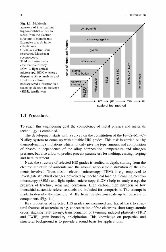
Next, the structure of selected HIS grades is studied in depth, starting from theelectron structure of austenite and the atomic nano-scale distribution of the ele-ments involved. Transmission electron microscopy (TEM) is e.g. employed toinvestigate structural changes provoked by mechanical loading. Scanning electronmicroscopy (SEM) and light optical microscopy (LOM) help to analyse e.g. theprogress of fracture, wear and corrosion. High carbon, high nitrogen or lowinterstitial austenitic reference steels are included for comparison. The attempt ismade to describe the structure of HIS from the electron scale up to the scale ofcomponents (Fig. 1.1).
Key properties of selected HIS grades are measured and traced back to struc-tural features of austenite as e.g. concentration of free electrons, short range atomicorder, stacking fault energy, transformation or twinning induced plasticity (TRIPand TWIP), grain boundary precipitation. This knowledge on properties andstructural background is to provide a sound basis for applications.
Fig. 1.1 Multiscaleapproach of investigatinghigh-interstitial austeniticsteels from the electronstructure to components.Examples are: ab initiocalculations,CESR = electron spinresonance, Mössbauerspectroscopy,TEM = transmissionelectron microscopy,LOM = light opticalmicroscopy, EDX = energydispersive X-ray analysis andEBSD = electronbackscattered diffraction in ascanning electron microscope(SEM), tensile tests
4 1 Introduction

References
1. Gavriljuk VG, Berns H (1999) High Nitrogen steel. Springer, Berlin2. Schaeffler AL (1949) Constitutional diagram for stainless steel weld metal. Metal progress
56:680–680B3. Shanina BD, Gavriljuk VG, Berns H, Schmalt F (2002) Concept of a new high-strength
austenitic stainless steel. Steel Res 73:105–1134. Schmalt F, Berns H, Gavriljuk VG (2004) Mechanical properties of a stainless austenitic
CrMnCN steel, Steel Grips 2. Suppl High Nitrogen Steels 2004:437–4465. Schmalt F (2004) Nutzung der Löslichkeit von C ? N in nichtrostenden Stählen, doctoral
thesis Ruhr University Bochum, see also Fortschr. Ber. (2005) VDI 5-702, VDI Verlag,Düsseldorf
6. Gavriljuk VG, Berns H (1999) Precipitates in tempered stainless martensitic steels alloyedwith nitrogen, carbon or both, Trans Tech Publ. Zürich Mat Sci Forum 318–320:71–80
7. Bernauer J, Speidel MO (2003) Effects of carbon in high-nitrogen corrosion-resistantaustenitic steels. In: Speidel MO, Kowanda C, Diener M (eds) Proceeding HNS 2003, vdfHochschulverlag AG, ETH Zürich, pp 159–168
8. Bernauer J, Saller G, Speidel MOl (2004) Combined influence of carbon and nitrogen on themechanical and corrosion properties of Cr-Mn steel grades, Steel Grips 2, Suppl HighNitrogen Steels, pp 529–537
9. Bernauer J (2004) Einfluss von Kohlenstoff als Legierungselement in stickstofflegiertenChrom—Mangan Stählen, doctoral thesis ETH Zürich, No. 15457
10. Müller R, Weintz R (1998) Ventilwerkstoffe für Verbrennungsmotoren, Materialwiss.u. Werkstofftechn 29:97–130
11. Bonaziz O, Allain S, Scott CD, Cugy P, Barbier D (2011) High manganese austenitictwinning induced plasticity steel: a review of the microstructure properties relationships,Current Opinions in Sol. State Mat Sci 15:141–168
12. Mujica Roncery L, Weber S, Theisen W (2010) Development of Mn-Cr-(C-N) corrosionresistant twinning induced plasticity steel: Thermodynamic and diffusion calculations,production, and characterization. Metall Mat Trans 41A(10):2471–2479
13. Mujica Roncery L (2010) Development of high-strength corrosion-resistant austenitic TWIPSteels with C ? N, doctoral thesis, Ruhr University Bochum
14. Berns H, Gavriljuk VG (2007) Steel of highest fracture energy, Key engineering materials,vols 345–346. Trans Tech Publications, pp 421–424
References 5
Chapter 2Constitution
2.1 General Remarks
The constitution of high interstitial steels describes the state of atomic order inthermodynamic equilibrium. It depends on the three variables of state: concen-tration of alloying elements in iron, temperature and pressure. A region that is inthe same state of order is known as a phase. Nitrogen is a volatile element andtherefore the gas phase and especially the partial pressure of N2 has to be takeninto account. The liquid phase appears during melting, solidification and welding.Of the solid state phases austenite, d-ferrite, carbides, nitrides and sigma phase areto be expected. To cope with such a complex alloy system the commercial soft-ware program THERMO-CALCTM, version R with TCFE4 database [1] was usedto calculate the constitution of multi-component HIS.
It depends on experimental data and theoretical models covering a wide rangeof steel compositions by minimizing the Gibb’s free energy [2]. The programprovides phase diagrams as isothermal or isoplethal sections through a system.Also the mole, mass or volume fraction of phases in a given steel may be plottedover the temperature. In addition the chemical composition of each phase isavailable. In the high temperature range from solidification to solution annealing,which are of practical importance, less deviation from the calculated equilibrium isto be expected than at lower temperatures. However during quenching the kineticsof precipitation are of interest only. It is shown in the next chapter that the atoms inhomogeneous austenite are not necessarily distributed evenly, but that microseg-regation (mm range) or short range atomic decomposition (clustering, nm range)may cause a chemical inhomogeneity which is not covered by the calculations.Tramp elements are not considered to reduce the computing time except formanufactured grades.
Limited experimental verification was in good agreement with the simulation.Therefore the calculated phase diagrams are taken as a reasonable guideline toreveal tendencies.
H. Berns et al., High Interstitial Stainless Austenitic Steels,Engineering Materials, DOI: 10.1007/978-3-642-33701-7_2,� Springer-Verlag Berlin Heidelberg 2013
7