Embed Size (px)
Citation preview
8/9/2019 Engineering Piping Design Guide Fibra de Vidrio
http://slidepdf.com/reader/full/engineering-piping-design-guide-fibra-de-vidrio 1/36
Engineering & Piping Design Guide
Manual No. E5000
October 15, 2003
SMITH FIBERCAST Fiberglass Reinforced Piping Systems
8/9/2019 Engineering Piping Design Guide Fibra de Vidrio
http://slidepdf.com/reader/full/engineering-piping-design-guide-fibra-de-vidrio 2/36
INTRODUCTION
INTRODUCTION
Smith Fibercast fiberglass reinforced epoxy and vinyl esterresin piping systems possess excellent corrosion resistance
and a combination of mechanical and physical properties thatoffer many advantages over traditional piping systems. SmithFibercast is recognized worldwide as a leading supplier of pip-ing systems for a wide range of chemical and industrial appli-
cations.This manual is provided as a reference resource for some of the specific properties of Smith Fibercast’s piping systems. Itis not intended to be a substitute for sound engineering prac-
tices as normally employed by professional design engineers.
Smith Fibercast has an international network of distributorsand trained field personnel to advise on proper installationtechniques. It is recommended they be consulted for assis-tance when installing Smith Fibercast piping systems. Thisnot only enhances the integrity of the piping system, but alsoincreases the efficiency and economy of the installation.
Additional information regarding installation techniques isprovided in the following Smith Fibercast installation manu-
als:
M a n u a l N o . F 6 0 0 0 Pipe Installation Handbook for Tapered Bell & Spigot Joints
M a n u a l N o . F6 0 8 0 Pipe Installation Handbook for Straight Socket Joints and
Butt & Wrap Joints
M an u a l N o . F6 3 0 0 Pipe Installation Handbook for Marine-Offshore Piping
GENERAL POLICY STATEMENT
It is the policy of Smith Fibercast to improve its products con-tinually. In accordance with that policy, the right is reservedto make changes in specifications, descriptions, and illustra-tive material contained in this manual as conditions warrant.The information contained herein is general in nature and isnot intended to express any warranty of any type whatsoevernor shall any be implied. In providing this technical informa-tion, Smith Fibercast has not been retained as and does notassume the role of engineering consultant to any user or cus-
tomer. Smith Fibercast does not accept and specifically dis-claims any responsibility or warranty for the design, specifica-tion, installation, or design performance of any fiberglasspiping system. We suggest that you visit our website or con-tact your distributor representative to verify that the litera-
ture and technical information is current.
SAFETY This safety alert symbol indicates an importantsafety message. When you see this symbol, bealert to the possibility of personal injury.
PIPING SYSTEMS
Epoxy Resin Systems:· Z-CORE® (High Performance Resin)
· CENTRICAST PLUS® RB-2530· CENTRICAST® RB-1520· GREEN THREAD®
· GREEN THREAD Performance Plus
· MARINE-OFFSHORE· GREEN THREAD 175· GREEN THREAD 175 Conductive· GREEN THREAD 250· GREEN THREAD 250 Cconductive· GREEN THREAD 250 Fire Resistant
· RED THREAD® II· RED THREAD II Performance Plus· RED THREAD II JP· SILVER STREAK ® (FGD Piping)
· CERAM CORE® (Ceramic-lined Piping)
· F-CHEM® (Custom Piping)
· HIGH PRESSURE Line Pipe andDownhole Tubing*
Vinyl Ester Systems:· CENTRICAST PLUS CL-2030· CENTRICAST CL-1520· CHEM THREAD®
· F-CHEM (Custom Piping)
Secondary Containment Systems:· DUALCAST®
· CLAM SHELL
* Available from FIBER GLASS SYSTEMS, A Varco Company, San Antonio, TexasPhone: (210) 434-5043 · FAX: (210) 434-7543
Website: http://www.starfiberglass.com
©Copyright 1982-2003, Varco L.P.
® and ™ Trademarks of Varco I/P, Inc.
Smith Fibercast has developed a computer programspecifically for our fiberglass products. This softwareprogram called Success By Design is available on our website at http://www.smithfibercast.com.
i Engineer ing & Pip ing Design Gu ide
8/9/2019 Engineering Piping Design Guide Fibra de Vidrio
http://slidepdf.com/reader/full/engineering-piping-design-guide-fibra-de-vidrio 3/36
Introduction ........................................................................i
Piping System Selection...................................................1
SEC TION 1 – Flo w Prope rti es .........................2
Preliminary Pipe Sizing ........................................................2
Detailed Pipe Sizing
A. Liquid Flow ...............................................................2B. Loss in Pipe Fittings..................................................4
C. Open Channel Flow...................................................5
D. Gas Flow....................................................................5
SECTION 2 – Above Ground System Design
Using Supp orts, Anch ors & G uides .................7
Piping Support Design
A. Support Bracket Design............................................7
B. Typical Guide Design................................................8
C. Anchor Design...........................................................9
D. Piping Support Span Design....................................11
SECT ION 3 – Tempe rature Effe cts ................12
System Design.....................................................................12
Thermal Properties and Characteristics.............................12
Fundamental Thermal Analysis Formulas
A. Thermal Expansion and Contraction......................13
B. Anchor Restraint Load............................................13
C. Guide Spacing..........................................................13
Flexibility Analysis and Design
A. Directional Change Design .....................................13
B. Expansion Loop Design ..........................................14
C. Expansion Joint Design ..........................................14
D. Heat Tracing............................................................15
E. Thermal Conductivity .............................................16
F. Thermal Expansion in Buried Pipe.........................16
G. Pipe Torque due to Thermal Expansion.................16
SEC TION 4 – Pipe Bur ial ................................17
Pipe Flexibility.....................................................................17
Burial Analysis
A. Soil Types.................................................................17
B. Soil Modulus ...........................................................18
Trench Excavation and Preparation
A. Trench Size..............................................................18
B. Trench Construction ...............................................18
C. Maximum Burial Depth ..........................................19
D. Roadway Crossing ..................................................19
Bedding and Backfill
A. Trench Bottom........................................................20
B. Backfill Materials....................................................20
C. Backfill Cover..........................................................20
D. High Water Table ...................................................20
SECTI ON 5 – Oth er Con side ratio ns ..............21
A. Abrasive Fluids..............................................................21
B. Low Temperature Applications ....................................21
C. Pipe Passing Through Walls or
Concrete Structures.......................................................21
D. Pipe Bending .................................................................21
E. Static Electricity............................................................22
F. Steam Cleaning .............................................................22
G. Thrust Blocks ................................................................22
H. Vacuum Service ............................................................22
I. Valves ...........................................................................22
J. Vibration.......................................................................23
K. Fluid (Water) Hammer.................................................23
L. Ultraviolet (U.V.) Radiation and Weathering ..............23
M. Fungal, Bacterial, and Rodent Resistance ...................23
SECTION 6 – Specifications
and Approvals ..................................................24
A. Compliance with National Specifications ....................24B. Approvals, Listings, and Compliance
with Regulations...........................................................24
A PP E N D I CE S
Appendix A Useful Formulas..........................................27
Appendix B Conversions ................................................30
L I S T O F T A B L E S
Table 1.0 Typical Applications............................................1
Table 1.1 Flow Resistance K Values for Fittings................4
Table 1.2 Typical Liquid Properties ...................................4
Table 1.3 Typical Gas Properties........................................6
Table 2.0 Minimum Support Width ...................................7
Table 2.1 Saddle Length .....................................................8
Table 4.0 Recommended Bedding and Backfill................18
Table 4.1 Nominal Trench Widths....................................18
Table 6.0 ASTM 2310 Classification.................................24
Table 6.1 Classifying Fiberglass Flanges
to ASTM D4024 ................................................25
Table 6.2 Classifying Fiberglass Pipe
Using ASTM D2310 and
Specifying Pipe Using ASTM D2996and D2997.........................................................26
TABLE OF CONTENTS
iiEngineer ing & Pip ing Design Guide
8/9/2019 Engineering Piping Design Guide Fibra de Vidrio
http://slidepdf.com/reader/full/engineering-piping-design-guide-fibra-de-vidrio 4/36
PRODUCT SELECTION and APPLICATION
PRODUCT SYSTEM SELECTION
When selecting a piping system for a particular application, itis important to consider the corrosive characteristics of themedia to which the pipe and fittings will be exposed, the nor-mal and potential upset temperatures and pressures of thesystem, as well as other environmental factors associated withthe project. Fiberglass reinforced plastic (FRP) piping sys-
tems provide excellent corrosion resistance, combined withhigh temperature and pressure capabilities, all at a relatively low installed cost. Smith Fibercast engineers, using epoxy, vinyl ester, and polyester resins, have developed a compre-hensive array of piping systems designed to meet the most de-manding application requirements. Piping systems are avail-
able with liners of varying type and thickness, with molded,fabricated, or filament wound fittings, ranging in size from 1"to 84"(25 to 2134 mm) in diameter.
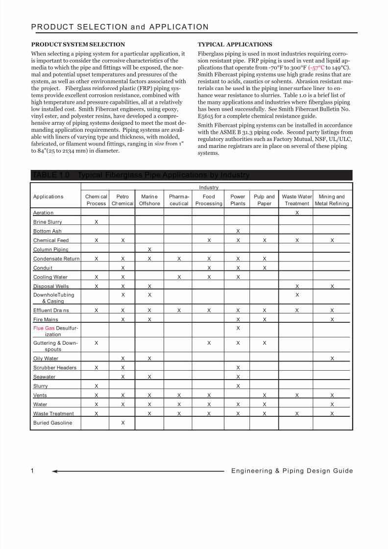
TYPICAL APPLICATIONS
Fiberglass piping is used in most industries requiring corro-sion resistant pipe. FRP piping is used in vent and liquid ap-plications that operate from -70°F to 300°F (-57°C to 149°C).Smith Fibercast piping systems use high grade resins that areresistant to acids, caustics or solvents. Abrasion resistant ma-terials can be used in the piping inner surface liner to en-
hance wear resistance to slurries. Table 1.0 is a brief list of the many applications and industries where fiberglass pipinghas been used successfully. See Smith Fibercast Bulletin No.E5615 for a complete chemical resistance guide.
Smith Fibercast piping systems can be installed in accordance with the ASME B 31.3 piping code. Second party listings fromregulatory authorities such as Factory Mutual, NSF, UL/ULC,and marine registrars are in place on several of these pipingsystems.
Industry
Appl ications Chemical Petro Marine Pharma- Food Power Pulp and Waste Water Mining and
Process Chemical Offshore ceutical Processing Plants Paper Treatment Metal Refining
Aerat ion X
Brine Slurry X
Bottom Ash X
Chemical Feed X X X X X X X
Column Piping X
Condensate Return X X X X X X X
Conduit X X X X
Cooling Water X X X X X
Disposal Wells X X X X XDownholeTubing X X X
& Casing
Effluent Drains X X X X X X X X X
Fire Mains X X X X X
Flue Gas Desulfur- X
ization
Guttering & Down- X X X X
spouts
Oily Water X X X
Scrubber Headers X X X
Seawater X X X
Slurry X X
Vents X X X X X X X X
Water X X X X X X X X
Waste Treatment X X X X X X X X
Buried Gasoline X
TABLE 1.0 Typical Fiberglass Pipe Applications by Industry
1 Engineer ing & Pip ing Design Guide
8/9/2019 Engineering Piping Design Guide Fibra de Vidrio
http://slidepdf.com/reader/full/engineering-piping-design-guide-fibra-de-vidrio 5/36
SECTION 1. FLOW PROPERTIES
The smooth interior surface of fiberglass pipe, combined withinside diameters larger than steel or thermoplastic pipe of thesame nominal diameter, yield significant flow advantages.This section provides design techniques for exploiting theflow capacity of fiberglass pipe.
PRELIMINARY PIPE SIZING
The determination of the pipe size required to transport a givenamount of fluid is the first step in designing a piping system.
Minimum recommended pipe diameters.
Clear Liquids
Eq. 1
Corrosive or erosive fluids
Eq. 2
Where:
d = Pipe inner diameter, inch
Q = Flow rate, gal/min (gpm)
Sg = Fluid specific gravity, dimensionless
p = Fluid density, lb/ft3
Recommended maximum fluid velocities
Clear fluids
Eq. 3
Corrosive or erosive fluids
Eq. 4
Where:
V = velocity, ft/sec
p = fluid density, lb/ft3
Typical fiberglass piping systems are operated at flow veloci-ties between 3 & 12 ft/sec.
DETAILED PIPE SIZING
A. Liquid Flow
Fluid flow characteristics are very sensitive to the absoluteroughness of the pipe inner surface. The absolute rough-ness of Smith Fibercast piping is (0.00021 inches) 1.7 x10⁻⁵ feet(1 ). This is less than 1/8 the average value for(non-corroded) new steel of (0.0018 inch) 15 x 10-5
feet(2). For ambient temperature water, the equivalentManning value (n) is 0.009 and the Hazen-Williams coef-ficient is 150.
The most commonly used pipe head loss formula is theDarcy-Weisbach equation.
Eq. 5
Where:
Hf = Pipe friction loss, ft(m)
f = Friction factor
L = Length of pipe run, ft (m)
D = Inner diameter, ft (m)
V = Fluid velocity, ft/sec (m/sec)
g = Acceleration of gravity, 32.2 ft/s2 (9.81 m/s2)
The friction factor is dependent on the flow conditions,pipe diameter and pipe smoothness. The flow conditionsare determined by the value of the Reynolds Number.There are four flow zones defined by the Reynolds Number;they are laminar, critical, transitional and turbulent.
For laminar flow (Reynolds Number below 2,000), thefriction factor is calculated by Eq.VI.
Eq. 6
Where Nr is the dimensionless Reynolds Number
Eq. 7
Where:
D = Pipe inner diameter, ft (m)
V = Fluid velocity, ft/sec (m/sec)
v = Fluid kinematic viscosity, ft2/sec (m2/sec)
Nr = Reynolds Number
f = Friction Factor
d
0.73 Q
Sg⋅
ρ0.33
:=
d
1.03 Q
Sg⋅
ρ0.33
:=
V 48
ρ0.33
:=
V24
ρ0.33
:=
Hf f L
D⋅
V2
2g⋅:=
1 Based on testing at Oklahoma State University in Stillwater, OK.
2 Cameron Hydraulic Data, Ingersoll-Rand, Seventeenth Edition, 1988.
Nr D V⋅
ν:=
SECTION 1. Flow Properties
f 64
Nr :=
2Engineer ing & Pip ing Design Guide
0.73 .
1.03 .
8/9/2019 Engineering Piping Design Guide Fibra de Vidrio
http://slidepdf.com/reader/full/engineering-piping-design-guide-fibra-de-vidrio 6/36
3 Engineer ing & Pip ing Design Gu ide3 Engineer ing & Pip ing Design Gu ide
SECTION 1. FLOW PROPERTIES
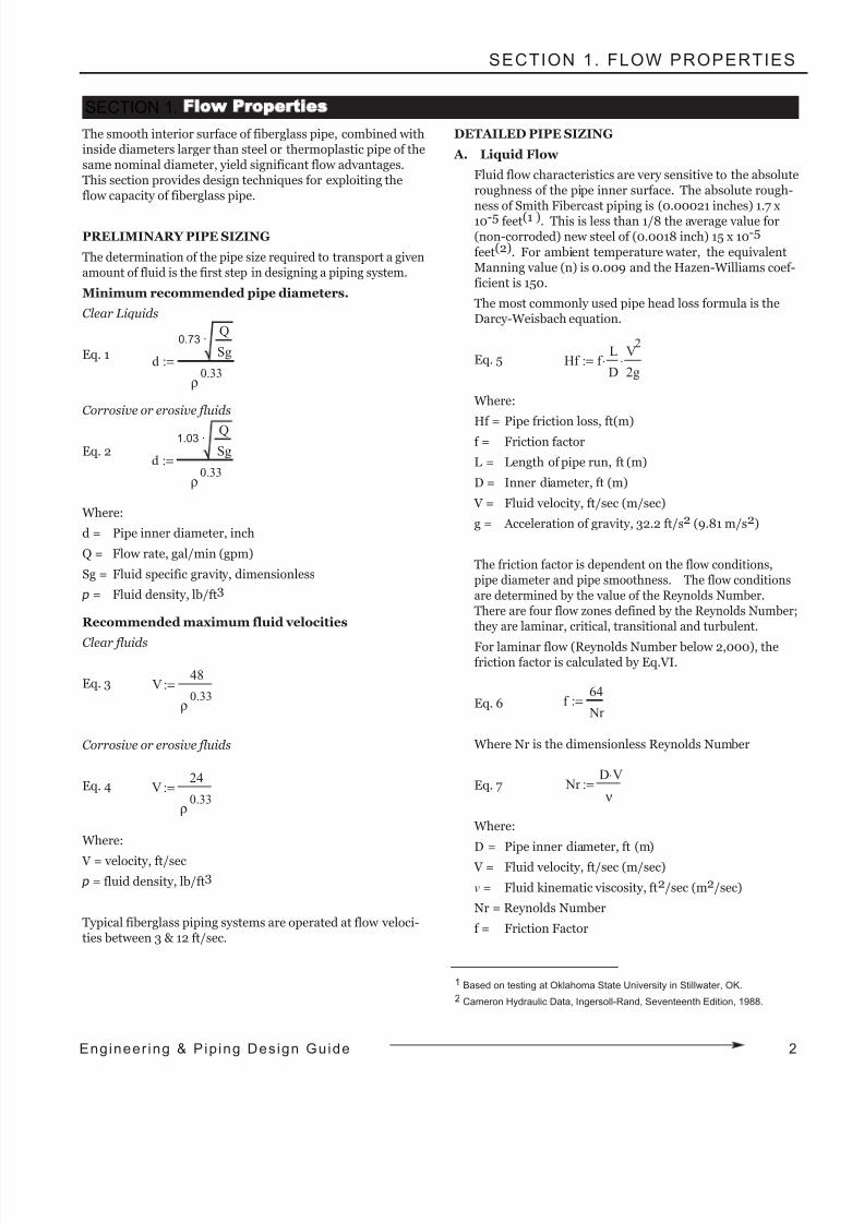
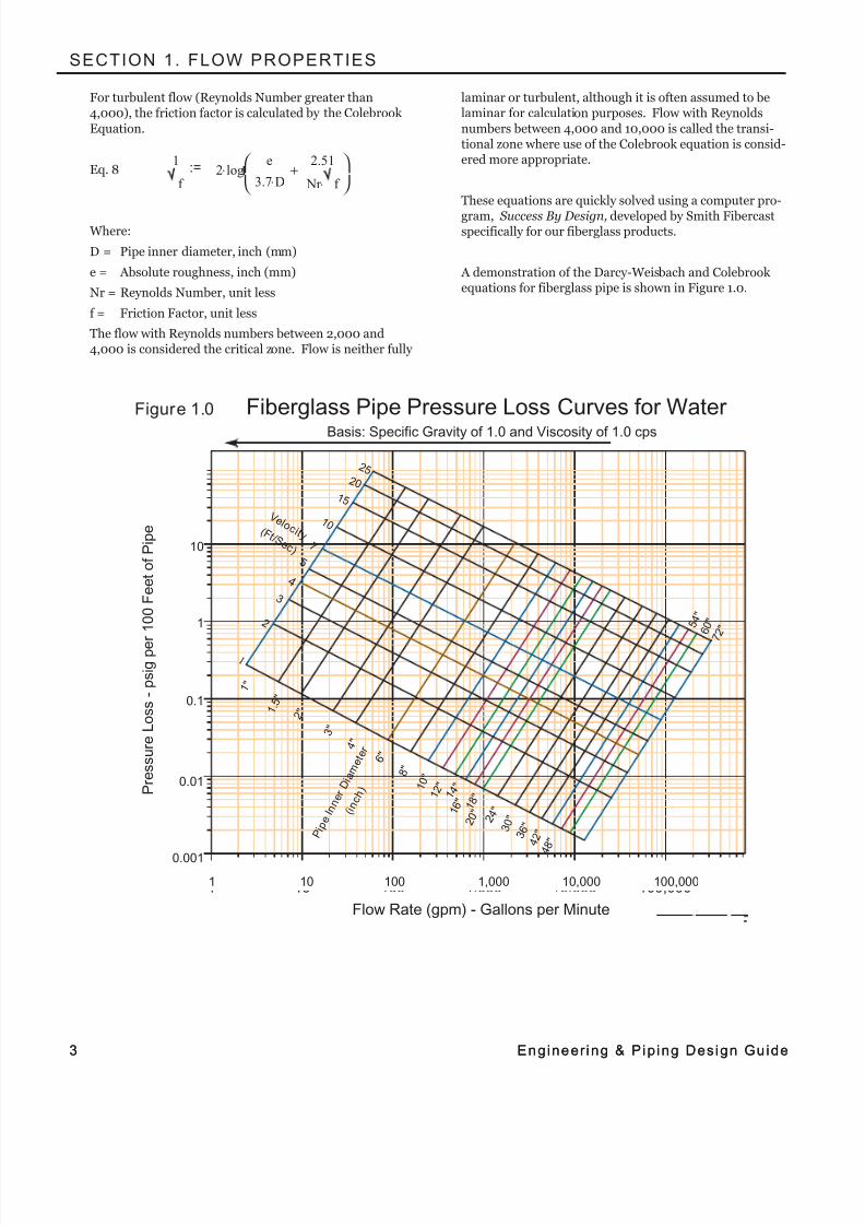
For turbulent flow (Reynolds Number greater than4,000), the friction factor is calculated by the Colebrook
Equation.
Eq. 8
Where:
D = Pipe inner diameter, inch (mm)
e = Absolute roughness, inch (mm)
Nr = Reynolds Number, unit less
f = Friction Factor, unit less
The flow with Reynolds numbers between 2,000 and4,000 is considered the critical zone. Flow is neither fully
laminar or turbulent, although it is often assumed to belaminar for calculation purposes. Flow with Reynolds
numbers between 4,000 and 10,000 is called the transi-tional zone where use of the Colebrook equation is consid-ered more appropriate.
These equations are quickly solved using a computer pro-
gram, Success By Design, developed by Smith Fibercastspecifically for our fiberglass products.
A demonstration of the Darcy-Weisbach and Colebrook equations for fiberglass pipe is shown in Figure 1.0.
1 10 100 1,000 10,000 100,000Flow Rate (gpm) - Gallons per Minute
0.001
0.01
0.1
1
10
2
34579
2
3457
2
3457
2
3457
2
34579
P r e s s u r e L o s s - p s i g p e r 1 0 0 F e e t o f P i p e
Fiberglass Pipe Pressure Loss Curves for Water Basis: Specific Gravity of 1.0 and Viscosity of 1.0 cps
4
5
2
7
1 0
1 5
2 0
2 5
V e l o c i t y ( F t / S e c )
1 "
1 . 5 "
2 "
3 "
4 "
6 "
8 "
1 0 "
1 2 "
1 4 "
1 6 "
1 8 "
2 0 "
2 4 "
3 0 "
3 6 "
4 2 "
4 8 "
5 4 "
6 0 "
7 2 "
1
3
P i p
e I n n e r D i a
m e t e r
( i n c h )
Figure 1.0
1
f
:= 2− log e
3.7 D⋅
2.51
Nr f ⋅+
⋅
10
1
0.1
0.01
0.001
1 10 100 1,000 10,000 100,000
Fiberglass Pipe Pressure Loss Curves for Water Basis: Specific Gravity of 1.0 and Viscosity of 1.0 cps
Flow Rate (gpm) - Gallons per Minute
8/9/2019 Engineering Piping Design Guide Fibra de Vidrio
http://slidepdf.com/reader/full/engineering-piping-design-guide-fibra-de-vidrio 7/36
SECTION 1. FLOW PROPERTIES
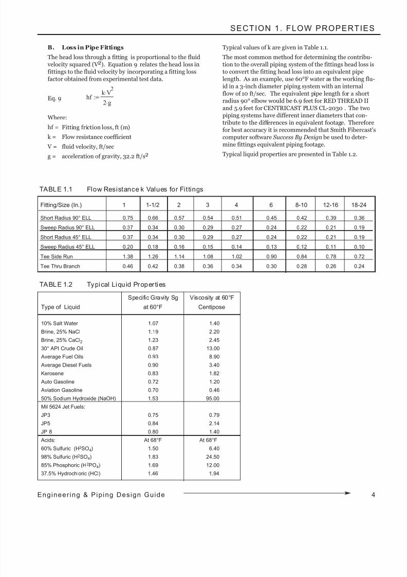
B. Loss in Pipe Fittings
The head loss through a fitting is proportional to the fluid velocity squared (V 2). Equation 9 relates the head loss infittings to the fluid velocity by incorporating a fitting lossfactor obtained from experimental test data.
Eq. 9
Where:
hf = Fitting friction loss, ft (m)
k = Flow resistance coefficient
V = fluid velocity, ft/sec
g = acceleration of gravity, 32.2 ft/s2
Typical values of k are given in Table 1.1.
The most common method for determining the contribu-tion to the overall piping system of the fittings head loss isto convert the fitting head loss into an equivalent pipelength. As an example, use 60°F water as the working flu-id in a 3-inch diameter piping system with an internalflow of 10 ft/sec. The equivalent pipe length for a short
radius 90° elbow would be 6.9 feet for RED THREAD IIand 5.9 feet for CENTRICAST PLUS CL-2030 . The twopiping systems have different inner diameters that con-tribute to the differences in equivalent footage. Thereforefor best accuracy it is recommended that Smith Fibercast'scomputer software Success By Design be used to deter-mine fittings equivalent piping footage.
Typical liquid properties are presented in Table 1.2.
Fitting/Size (In.) 1 1-1/2 2 3 4 6 8-10 12-16 18-24
Short Radius 90° ELL 0.75 0.66 0.57 0.54 0.51 0.45 0.42 0.39 0.36
Sweep Radius 90° ELL 0.37 0.34 0.30 0.29 0.27 0.24 0.22 0.21 0.19
Short Radius 45° ELL 0.37 0.34 0.30 0.29 0.27 0.24 0.22 0.21 0.19
Sweep Radius 45° ELL 0.20 0.18 0.16 0.15 0.14 0.13 0.12 0.11 0.10
Tee Side Run 1.38 1.26 1.14 1.08 1.02 0.90 0.84 0.78 0.72
Tee Thru Branch 0.46 0.42 0.38 0.36 0.34 0.30 0.28 0.26 0.24
TABLE 1.1 Flow Resistance k Values for Fittings
TABLE 1.2 Typical Liquid Proper ties
Specific Gravity Sg Viscosity at 60°F
Type of Liquid at 60°F Centipose
10% Salt Water 1.07 1.40
Brine, 25% NaCl 1.19 2.20
Brine, 25% CaCl2 1.23 2.45
30° API Crude Oil 0.87 13.00
Average Fuel Oils 0.93 8.90
Average Diesel Fuels 0.90 3.40
Kerosene 0.83 1.82
Auto Gasoline 0.72 1.20
Aviation Gasoline 0.70 0.46
50% Sodium Hydroxide (NaOH) 1.53 95.00
Mil 5624 Jet Fuels:
JP3 0.75 0.79
JP5 0.84 2.14
JP 8 0.80 1.40
Acids: At 68°F At 68°F
60% Sulfuric (H2SO4) 1.50 6.40
98% Sulfuric (H2SO4) 1.83 24.50
85% Phosphoric (H2PO4) 1.69 12.00
37.5% Hydrochloric (HCl) 1.46 1.94
hf k V
2⋅
2 g⋅:=
4Engineer ing & Pip ing Design Guide
8/9/2019 Engineering Piping Design Guide Fibra de Vidrio
http://slidepdf.com/reader/full/engineering-piping-design-guide-fibra-de-vidrio 8/36
5 Engineer ing & Pip ing Design Gu ide
SECTION 1. FLOW PROPERTIES
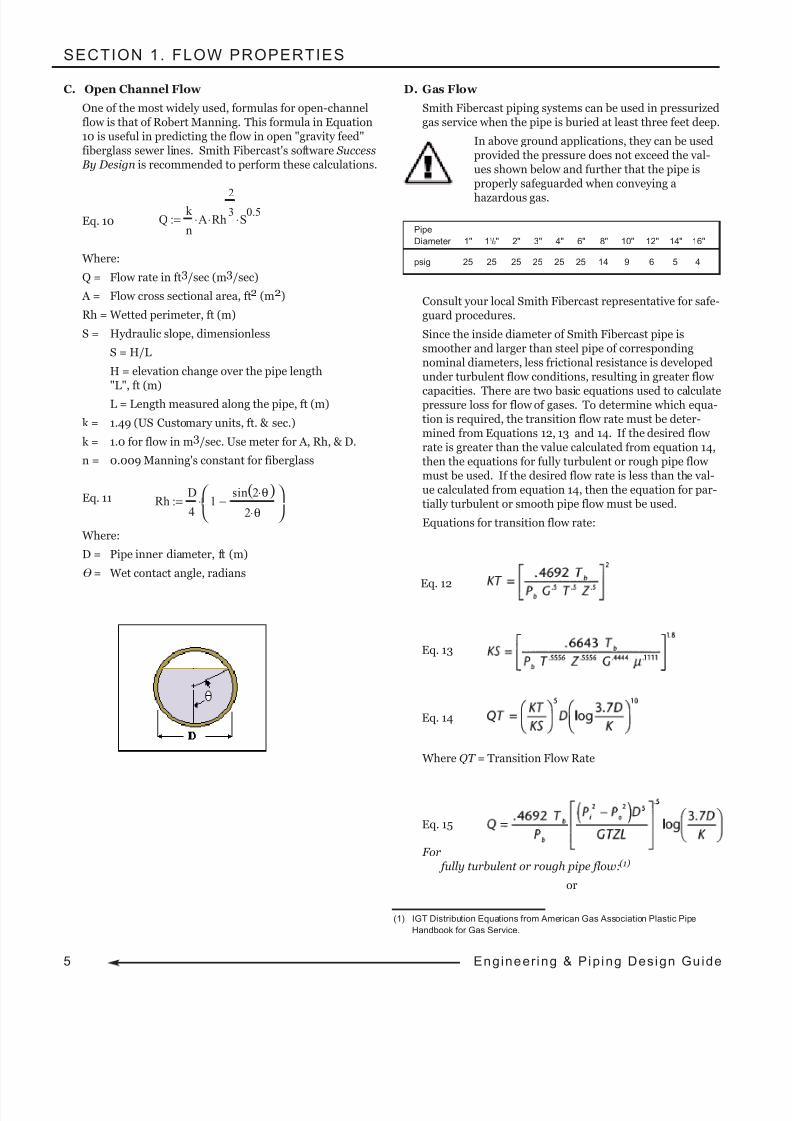
C. Open Channel Flow
One of the most widely used, formulas for open-channelflow is that of Robert Manning. This formula in Equation10 is useful in predicting the flow in open "gravity feed"fiberglass sewer lines. Smith Fibercast's software Success By Design is recommended to perform these calculations.
Eq. 10
Where:
Q = Flow rate in ft3/sec (m3/sec)
A = Flow cross sectional area, ft2 (m2)
Rh = Wetted perimeter, ft (m)
S = Hydraulic slope, dimensionless
S = H/L
H = elevation change over the pipe length"L", ft (m)
L = Length measured along the pipe, ft (m)
k = 1.49 (US Customary units, ft. & sec.)
k = 1.0 for flow in m3/sec. Use meter for A, Rh, & D.
n = 0.009 Manning's constant for fiberglass
Eq. 11
Where:
D = Pipe inner diameter, ft (m)
= Wet contact angle, radians
D. Gas Flow
Smith Fibercast piping systems can be used in pressurizedgas service when the pipe is buried at least three feet deep.
In above ground applications, they can be usedprovided the pressure does not exceed the val-ues shown below and further that the pipe isproperly safeguarded when conveying a
hazardous gas.
Consult your local Smith Fibercast representative for safe-guard procedures.
Since the inside diameter of Smith Fibercast pipe issmoother and larger than steel pipe of correspondingnominal diameters, less frictional resistance is developedunder turbulent flow conditions, resulting in greater flow
capacities. There are two basic equations used to calculatepressure loss for flow of gases. To determine which equa-tion is required, the transition flow rate must be deter-mined from Equations 12, 13 and 14. If the desired flow rate is greater than the value calculated from equation 14,then the equations for fully turbulent or rough pipe flow must be used. If the desired flow rate is less than the val-ue calculated from equation 14, then the equation for par-tially turbulent or smooth pipe flow must be used.
Equations for transition flow rate:
Where QT = Transition Flow Rate
For fully turbulent or rough pipe flow:(1)
or
Q k
nA⋅ Rh
23
⋅ S0.5
⋅:=
Rh D
41
sin 2 θ⋅( )2 θ⋅
−
⋅:=
Pipe
Diameter 1" 11/2" 2" 3" 4" 6" 8" 10" 12" 14" 16"
psig 25 25 25 25 25 25 14 9 6 5 4
Eq. 12
Eq. 13
Eq. 14
(1) IGT Distribution Equations from American Gas Association Plastic Pipe
Handbook for Gas Service.
Eq. 15
8/9/2019 Engineering Piping Design Guide Fibra de Vidrio
http://slidepdf.com/reader/full/engineering-piping-design-guide-fibra-de-vidrio 9/36
SECTION 1. FLOW PROPERTIES
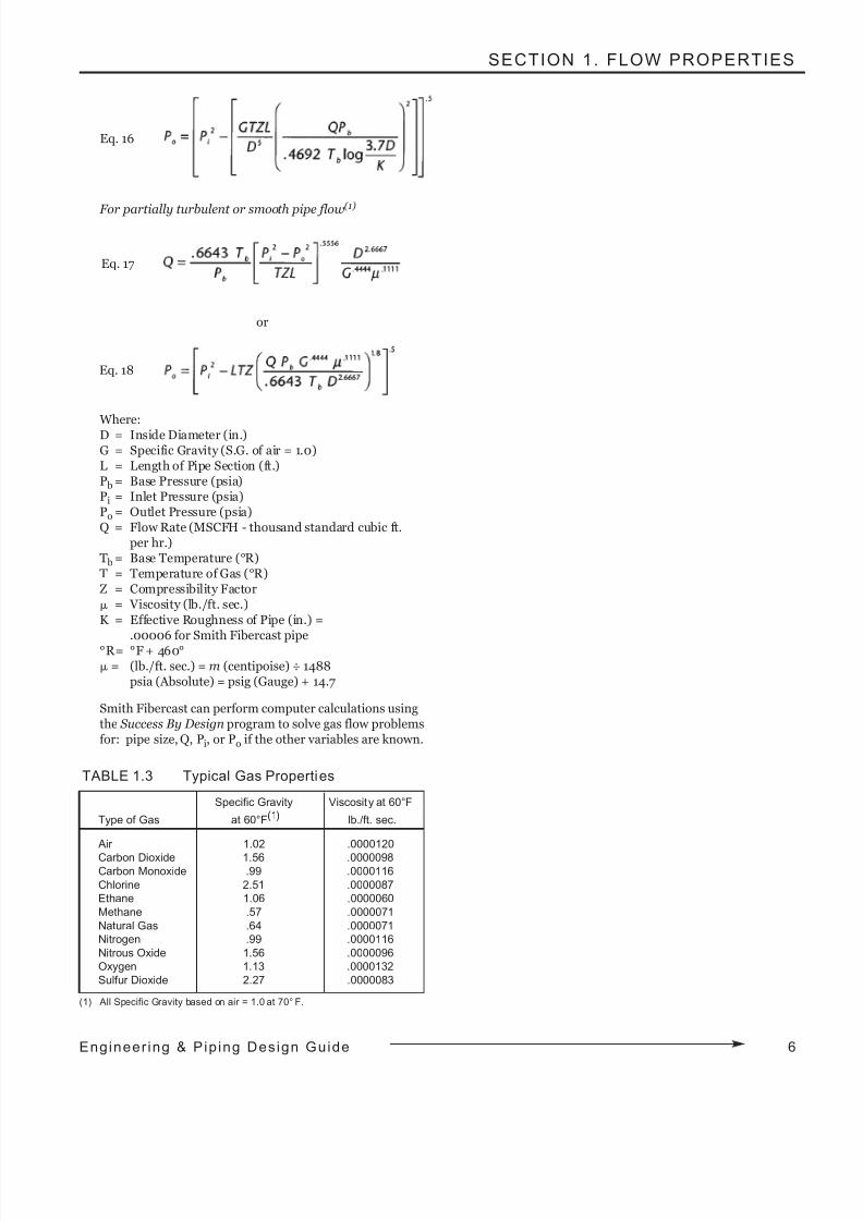
For partially turbulent or smooth pipe flow(1)
or
Where:D = Inside Diameter (in.)G = Specific Gravity (S.G. of air = 1.0)L = Length of Pipe Section (ft.)P b = Base Pressure (psia)Pi = Inlet Pressure (psia)Po = Outlet Pressure (psia)Q = Flow Rate (MSCFH - thousand standard cubic ft.
per hr.)T b = Base Temperature (°R)T = Temperature of Gas (°R)Z = Compressibility Factor
µ = Viscosity (lb./ft. sec.)
K = Effective Roughness of Pipe (in.) =
.00006 for Smith Fibercast pipe°R= °F + 460°µ = (lb./ft. sec.) = m (centipoise) ÷ 1488
psia (Absolute) = psig (Gauge) + 14.7
Smith Fibercast can perform computer calculations usingthe Success By Design program to solve gas flow problemsfor: pipe size, Q, Pi, or Po if the other variables are known.
TABLE 1.3 Typical Gas Properties
Specific Gravity Viscosity at 60°F
Type of Gas at 60°F(1) lb./ft. sec.
Air 1.02 .0000120
Carbon Dioxide 1.56 .0000098Carbon Monoxide .99 .0000116
Chlorine 2.51 .0000087
Ethane 1.06 .0000060
Methane .57 .0000071
Natural Gas .64 .0000071
Nitrogen .99 .0000116
Nitrous Oxide 1.56 .0000096
Oxygen 1.13 .0000132
Sulfur Dioxide 2.27 .0000083
(1) All Specific Gravity based on air = 1.0 at 70° F.
Eq. 16
Eq. 17
Eq. 18
6Engineer ing & Pip ing Design Guide
8/9/2019 Engineering Piping Design Guide Fibra de Vidrio
http://slidepdf.com/reader/full/engineering-piping-design-guide-fibra-de-vidrio 10/36
7 Engineer ing & Pip ing Design Gu ide
SECTION 2. SUPPORTS, ANCHORS and GUIDES
PIPING SUPPORT DESIGN Above ground piping systems may be designed as restrainedor unrestrained. Selection of the design method is dependenton variables such as operating temperature, flow rates, pres-sures and piping layout. System designs combining the two
methods often lead to the most structurally efficient and eco-nomical piping layout.
Unrestrained System Design
The unrestrained system is often referred to as a "simplesupported" design. It makes use of the inherent flexibility of fiberglass pipe to safely absorb deflections and bendingstresses. Simple pipe hangers or steel beams are used toprovide vertical support to the pipe. These simple sup-ports allow the piping system to expand and contract freely resulting in small axial stresses in the piping system. Longstraight runs often employ changes-in-direction to safely absorb movement due to thermal expansion and contrac-tions, flow rate changes, and internal pressure.
Restrained System DesignThe restrained system is often referred to as an "anchoredand guided design". The low modulus of elasticity forSmith Fibercast piping translates to significantly smallerthermal forces when compared to steel. Anchors are em-
ployed to restrain axial movement and provide verticalsupport in horizontal pipelines. Anchors used to restrainthermal expansion create compressive forces in thepipeline. These forces must be controlled by the use of pipe guides to prevent the pipe from buckling. In cases where axial loads created by anchoring a pipe run are ex-cessively high, the use of expansion loops or expansion joints must be employed. When using anchors, the effect
of system contraction should be considered. See the ther-mal analysis section for more thorough information onhandling thermal loads.
FIBERGLASS PIPING SYSTEM "SUPPORT"TERMINOLOGY Fiberglass piping engineers use three basic structural compo-nents to install a piping system. They are the support,
anchor, and guide.
SupportPipe supports hold the pipe in position and prevent excessivedeflections due to the weight of the pipe, fluid, external insu-lation and other load sources.
AnchorPipe anchors restrain the pipe against axial movement or ap-plied forces. These forces may result from thermal loads, wa-ter hammer, vibrating equipment, or externally applied me-chanical loads.
GuidePipe guides prevent lateral (side-to-side) movement of thepipe. Guides are required to prevent the pipe from buckling
under compressive loading. For example: When anchors areused to control thermal expansion, guides are always re-quired.
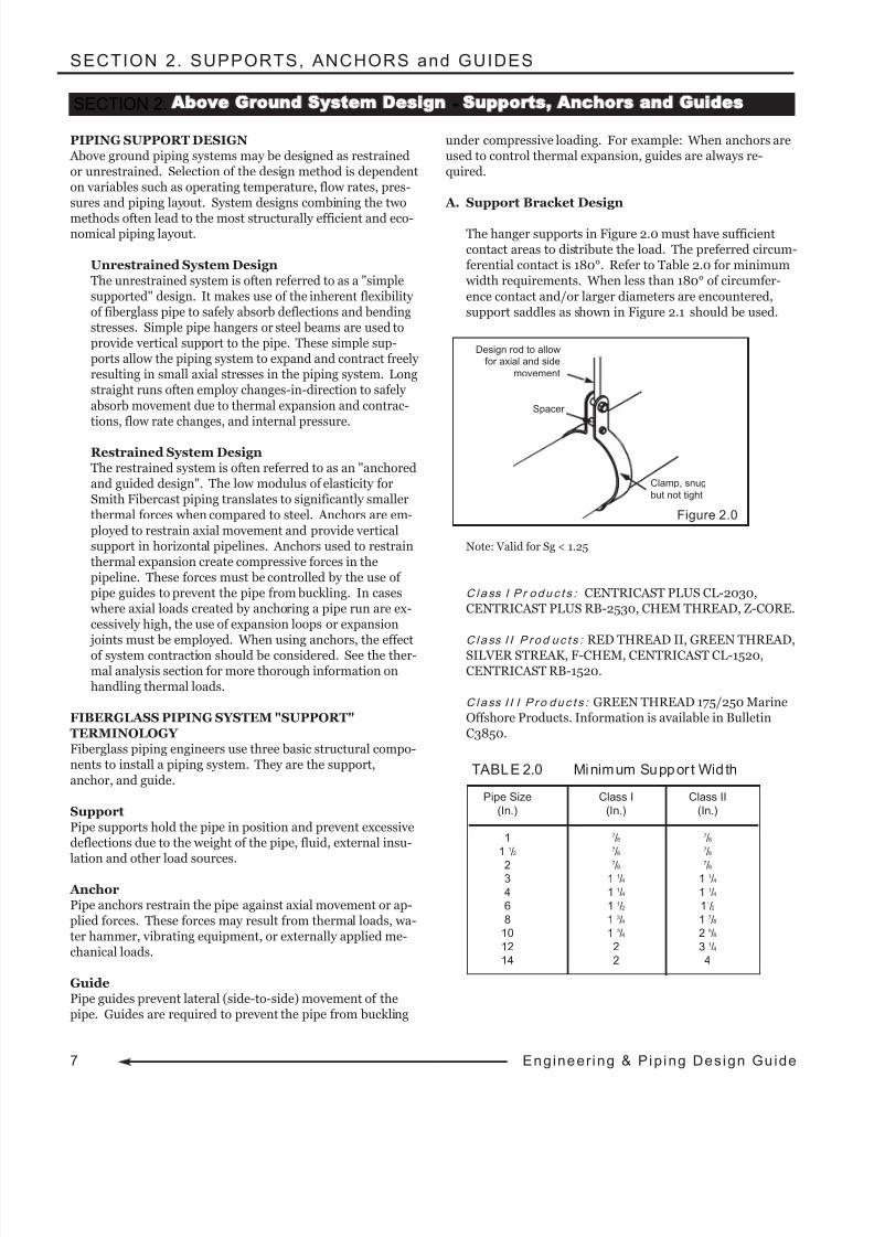
A. Support Bracket Design
The hanger supports in Figure 2.0 must have sufficientcontact areas to distribute the load. The preferred circum-ferential contact is 180°. Refer to Table 2.0 for minimum width requirements. When less than 180° of circumfer-
ence contact and/or larger diameters are encountered,support saddles as shown in Figure 2.1 should be used.
Note: Valid for Sg < 1.25
C la ss I P r oduc t s : CENTRICAST PLUS CL-2030,CENTRICAST PLUS RB-2530, CHEM THREAD, Z-CORE.
C la ss I I P r od uc t s : RED THREAD II, GREEN THREAD,
SILVER STREAK, F-CHEM, CENTRICAST CL-1520,CENTRICAST RB-1520.
C la ss I I I P r o duc t s : GREEN THREAD 175/250 MarineOffshore Products. Information is available in BulletinC3850.
Pipe Size Class I Class II
(In.) (In.) (In.)
1 7/8 7/8
1 1/2 7/8 7/8
27
/87
/83 1 1/4 1 1/4
4 1 1/4 1 1/4
6 1 1/2 11/2
8 1 3/4 1 7/8
10 1 3/4 2 5/8
12 2 3 1/4
14 2 4
TABLE 2.0 Minimum Suppor t Width
Figure 2.0
SECTION 2. Above Ground System Design - Supports Anchors and Guides
Design rod to allowfor axial and side
movement
Spacer
Clamp, snug
but not tight
8/9/2019 Engineering Piping Design Guide Fibra de Vidrio
http://slidepdf.com/reader/full/engineering-piping-design-guide-fibra-de-vidrio 11/36
SECTION 2. SUPPORTS, ANCHORS and GUIDES
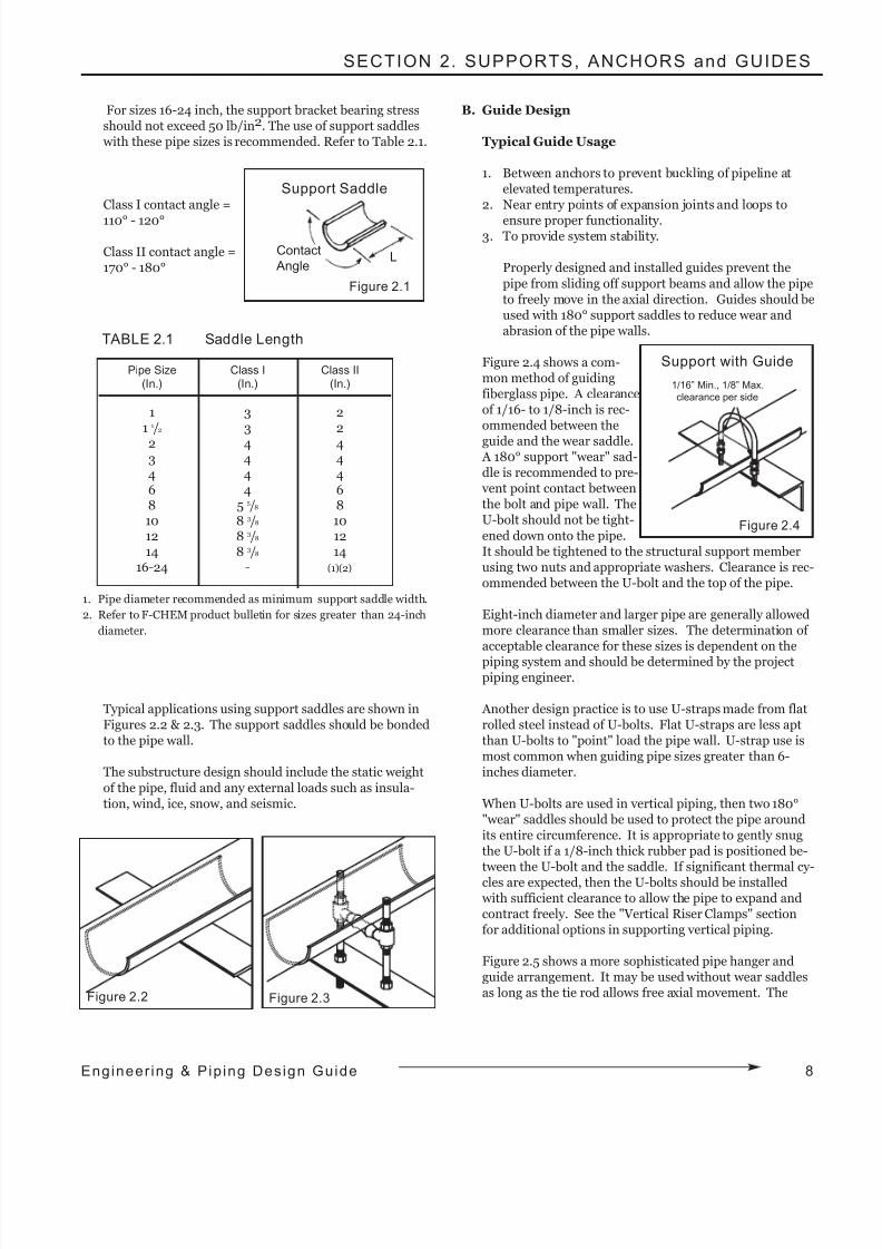
For sizes 16-24 inch, the support bracket bearing stressshould not exceed 50 lb/in2. The use of support saddles with these pipe sizes is recommended. Refer to Table 2.1.
Class I contact angle =
110° - 120°
Class II contact angle =170° - 180°
1. Pipe diameter recommended as minimum support saddle width.
2. Refer to F-CHEM product bulletin for sizes greater than 24-inch
diameter.
Typical applications using support saddles are shown inFigures 2.2 & 2.3. The support saddles should be bondedto the pipe wall.
The substructure design should include the static weight
of the pipe, fluid and any external loads such as insula-tion, wind, ice, snow, and seismic.
B. Guide Design
Typical Guide Usage
1. Between anchors to prevent buckling of pipeline atelevated temperatures.
2. Near entry points of expansion joints and loops to
ensure proper functionality.3. To provide system stability.
Properly designed and installed guides prevent the
pipe from sliding off support beams and allow the pipeto freely move in the axial direction. Guides should beused with 180° support saddles to reduce wear andabrasion of the pipe walls.
Figure 2.4 shows a com-mon method of guidingfiberglass pipe. A clearanceof 1/16- to 1/8-inch is rec-ommended between the
guide and the wear saddle. A 180° support "wear" sad-dle is recommended to pre- vent point contact betweenthe bolt and pipe wall. TheU-bolt should not be tight-
ened down onto the pipe.It should be tightened to the structural support memberusing two nuts and appropriate washers. Clearance is rec-ommended between the U-bolt and the top of the pipe.
Eight-inch diameter and larger pipe are generally allowedmore clearance than smaller sizes. The determination of acceptable clearance for these sizes is dependent on the
piping system and should be determined by the projectpiping engineer.
Another design practice is to use U-straps made from flatrolled steel instead of U-bolts. Flat U-straps are less aptthan U-bolts to "point" load the pipe wall. U-strap use ismost common when guiding pipe sizes greater than 6-inches diameter.
When U-bolts are used in vertical piping, then two 180°"wear" saddles should be used to protect the pipe aroundits entire circumference. It is appropriate to gently snugthe U-bolt if a 1/8-inch thick rubber pad is positioned be-tween the U-bolt and the saddle. If significant thermal cy-cles are expected, then the U-bolts should be installed with sufficient clearance to allow the pipe to expand andcontract freely. See the "Vertical Riser Clamps" sectionfor additional options in supporting vertical piping.
Figure 2.5 shows a more sophisticated pipe hanger andguide arrangement. It may be used without wear saddlesas long as the tie rod allows free axial movement. The
Pipe Size Class I Class II
(In.) (In.) (In.)
1 3 21 1/2 3 22 4 43 4 44 4 46 4 68 5 5/8 810 8 3/8 1012 8 3/8 1214 8 3/8 14
16-24 - (1)(2)
TABLE 2.1 Saddle Length
Figure 2.2 Figure 2.3
Figure 2.4
Support with Guide
1/16” Min., 1/8” Max.
clearance per side
8Engineer ing & Pip ing Design Guide
Support Saddle
Figure 2.1
Contact
AngleL
8/9/2019 Engineering Piping Design Guide Fibra de Vidrio
http://slidepdf.com/reader/full/engineering-piping-design-guide-fibra-de-vidrio 12/36
9 Engineer ing & Pip ing Design Gu ide
SECTION 2. SUPPORTS, ANCHORS and GUIDES
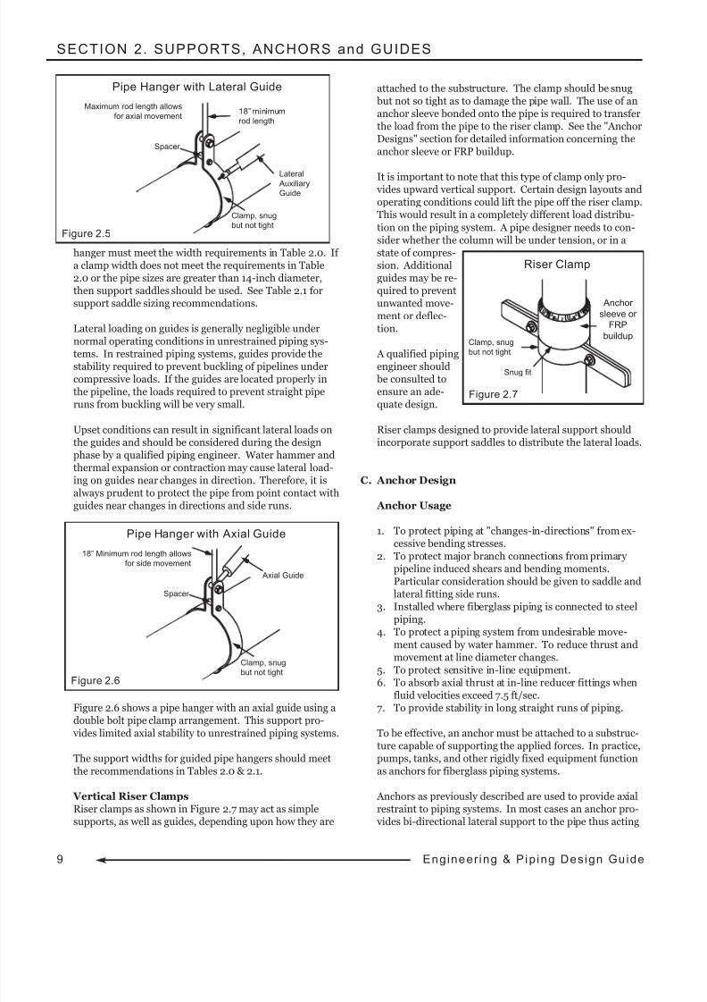
hanger must meet the width requirements in Table 2.0. If a clamp width does not meet the requirements in Table2.0 or the pipe sizes are greater than 14-inch diameter,then support saddles should be used. See Table 2.1 forsupport saddle sizing recommendations.
Lateral loading on guides is generally negligible undernormal operating conditions in unrestrained piping sys-
tems. In restrained piping systems, guides provide thestability required to prevent buckling of pipelines undercompressive loads. If the guides are located properly inthe pipeline, the loads required to prevent straight piperuns from buckling will be very small.
Upset conditions can result in significant lateral loads onthe guides and should be considered during the designphase by a qualified piping engineer. Water hammer andthermal expansion or contraction may cause lateral load-ing on guides near changes in direction. Therefore, it isalways prudent to protect the pipe from point contact withguides near changes in directions and side runs.
Figure 2.6 shows a pipe hanger with an axial guide using adouble bolt pipe clamp arrangement. This support pro-
vides limited axial stability to unrestrained piping systems.
The support widths for guided pipe hangers should meetthe recommendations in Tables 2.0 & 2.1.
Vertical Riser ClampsRiser clamps as shown in Figure 2.7 may act as simplesupports, as well as guides, depending upon how they are
attached to the substructure. The clamp should be snug but not so tight as to damage the pipe wall. The use of ananchor sleeve bonded onto the pipe is required to transferthe load from the pipe to the riser clamp. See the "AnchorDesigns" section for detailed information concerning theanchor sleeve or FRP buildup.
It is important to note that this type of clamp only pro- vides upward vertical support. Certain design layouts andoperating conditions could lift the pipe off the riser clamp.This would result in a completely different load distribu-
tion on the piping system. A pipe designer needs to con-sider whether the column will be under tension, or in astate of compres-sion. Additionalguides may be re-quired to preventunwanted move-ment or deflec-tion.
A qualified pipingengineer should be consulted toensure an ade-quate design.
Riser clamps designed to provide lateral support shouldincorporate support saddles to distribute the lateral loads.
C. Anchor Design
Anchor Usage
1. To protect piping at "changes-in-directions" from ex-cessive bending stresses.
2. To protect major branch connections from primary pipeline induced shears and bending moments.Particular consideration should be given to saddle andlateral fitting side runs.
3. Installed where fiberglass piping is connected to steelpiping.
4. To protect a piping system from undesirable move-
ment caused by water hammer. To reduce thrust andmovement at line diameter changes.
5. To protect sensitive in-line equipment.6. To absorb axial thrust at in-line reducer fittings when
fluid velocities exceed 7.5 ft/sec.7. To provide stability in long straight runs of piping.
To be effective, an anchor must be attached to a substruc-ture capable of supporting the applied forces. In practice,pumps, tanks, and other rigidly fixed equipment functionas anchors for fiberglass piping systems.
Anchors as previously described are used to provide axialrestraint to piping systems. In most cases an anchor pro- vides bi-directional lateral support to the pipe thus acting
Figure 2.5
Maximum rod length allows
for axial movement
Spacer
Clamp, snug
but not tight
Lateral Auxiliary
Guide
18” minimum
rod length
Pipe Hanger with Lateral Guide
Figure 2.6
18” Minimum rod length allows
for side movement
Spacer
Clamp, snug
but not tight
Axial Guide
Pipe Hanger with Axial Guide
Figure 2.7
Riser Clamp
Anchor
sleeve or
FRP
buildup
Snug fit
Clamp, snug
but not tight
8/9/2019 Engineering Piping Design Guide Fibra de Vidrio
http://slidepdf.com/reader/full/engineering-piping-design-guide-fibra-de-vidrio 13/36
SECTION 2. SUPPORTS, ANCHORS and GUIDES
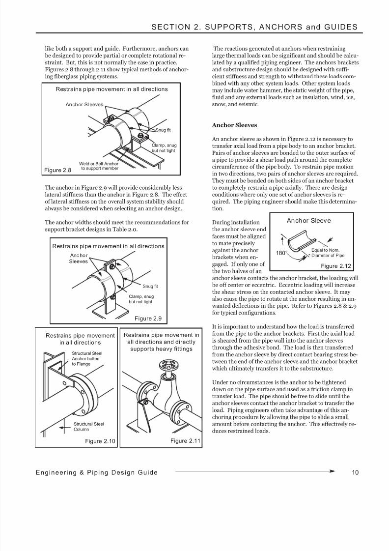
like both a support and guide. Furthermore, anchors can be designed to provide partial or complete rotational re-straint. But, this is not normally the case in practice.Figures 2.8 through 2.11 show typical methods of anchor-ing fiberglass piping systems.
The anchor in Figure 2.9 will provide considerably less
lateral stiffness than the anchor in Figure 2.8. The effectof lateral stiffness on the overall system stability shouldalways be considered when selecting an anchor design.
The anchor widths should meet the recommendations forsupport bracket designs in Table 2.0.
The reactions generated at anchors when restraininglarge thermal loads can be significant and should be calcu-lated by a qualified piping engineer. The anchors bracketsand substructure design should be designed with suffi-cient stiffness and strength to withstand these loads com- bined with any other system loads. Other system loadsmay include water hammer, the static weight of the pipe,
fluid and any external loads such as insulation, wind, ice,snow, and seismic.
Anchor Sleeves
An anchor sleeve as shown in Figure 2.12 is necessary totransfer axial load from a pipe body to an anchor bracket.Pairs of anchor sleeves are bonded to the outer surface of a pipe to provide a shear load path around the completecircumference of the pipe body. To restrain pipe motionin two directions, two pairs of anchor sleeves are required.They must be bonded on both sides of an anchor bracketto completely restrain a pipe axially. There are design
conditions where only one set of anchor sleeves is re-quired. The piping engineer should make this determina-tion.
During installationthe anchor sleeve end
faces must be alignedto mate precisely against the anchor brackets when en-gaged. If only one of the two halves of ananchor sleeve contacts the anchor bracket, the loading will be off center or eccentric. Eccentric loading will increase
the shear stress on the contacted anchor sleeve. It may also cause the pipe to rotate at the anchor resulting in un- wanted deflections in the pipe. Refer to Figures 2.8 & 2.9for typical configurations.
It is important to understand how the load is transferredfrom the pipe to the anchor brackets. First the axial loadis sheared from the pipe wall into the anchor sleevesthrough the adhesive bond. The load is then transferred
from the anchor sleeve by direct contact bearing stress be-tween the end of the anchor sleeve and the anchor bracket which ultimately transfers it to the substructure.
Under no circumstances is the anchor to be tighteneddown on the pipe surface and used as a friction clamp totransfer load. The pipe should be free to slide until theanchor sleeves contact the anchor bracket to transfer theload. Piping engineers often take advantage of this an-choring procedure by allowing the pipe to slide a smallamount before contacting the anchor. This effectively re-duces restrained loads.
Figure 2.8
Anchor Sleeves
Snug fit
Clamp, snug
but not tight
Weld or Bolt Anchor to support member
Restrains pipe movement in all directions
Figure 2.9
Restrains pipe movement in all directions
Snug fit
Clamp, snug
but not tight
Anchor
Sleeves
Figure 2.10
Restrains pipe movement
in all directions
Structural Steel
Anchor bolted
to Flange
Structural Steel
Column
Figure 2.11
Figure 2.12
Anchor Sleeve
180°Equal to Nom.
Diameter of Pipe
Restrains pipe movement in
all directions and directly
supports heavy fittings
10Engineer ing & Pip ing Design Guide
8/9/2019 Engineering Piping Design Guide Fibra de Vidrio
http://slidepdf.com/reader/full/engineering-piping-design-guide-fibra-de-vidrio 14/36
11 Eng ineer ing & Pip ing Design Gu ide
SECTION 2. SUPPORTS, ANCHORS and GUIDES
Split repair couplings, split fiberglass pipe sections orhand layups of fiberglass and resin are commonly used asanchor sleeves. Contact your fiberglass distributor to de-termine the most appropriate choice for Smith Fibercast's wide variety of piping products.
D. Piping Support Span Design
A support span is the distance between two pipe supports.Proper support span lengths ensure the pipe deflectionsand bending stresses are within safe working limits. For
static weight loads, it is standard practice to limit themaximum span deflection in horizontal pipe lines to ½"and the bending stresses to 1/8 of the ultimate allowable bending stress. Smith Fibercast applies these design lim-its to the engineering analysis used to determine the al-lowable support spans.
Span Analysis Methodology
The maximum allowable piping support spans are deter-
mined using the "Three Moment Equations" for uniformly loaded continuous beams. The equations may be modifiedto represent various end conditions, load types and evensupport settlements. Refer to Appendix A for the funda-mental equations. Smith Fibercast uses these equationsto calculate the bending moments in piping spans. The
pipe bending stresses and deflections are then evaluatedfor compliance with the aforementioned design criteria.
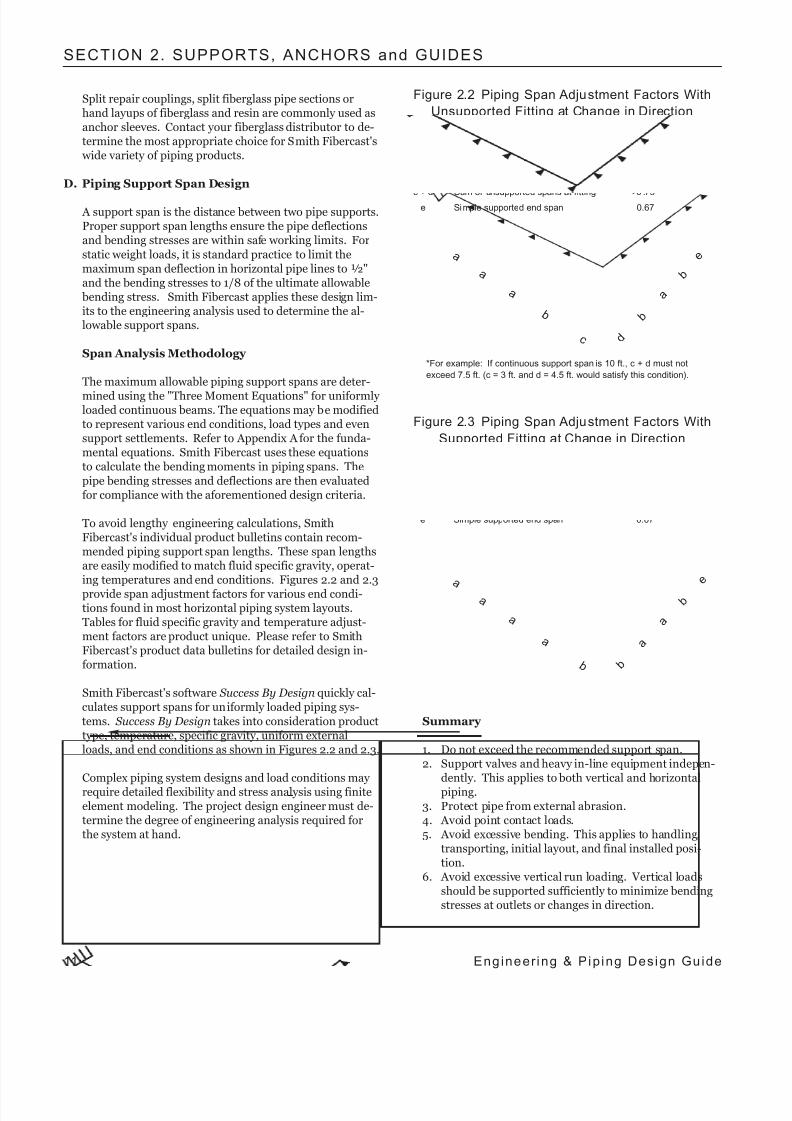
To avoid lengthy engineering calculations, SmithFibercast's individual product bulletins contain recom-mended piping support span lengths. These span lengthsare easily modified to match fluid specific gravity, operat-ing temperatures and end conditions. Figures 2.2 and 2.3
provide span adjustment factors for various end condi-tions found in most horizontal piping system layouts.Tables for fluid specific gravity and temperature adjust-ment factors are product unique. Please refer to SmithFibercast's product data bulletins for detailed design in-formation.
Smith Fibercast's software Success By Design quickly cal-culates support spans for uniformly loaded piping sys-
tems. Success By Design takes into consideration producttype, temperature, specific gravity, uniform externalloads, and end conditions as shown in Figures 2.2 and 2.3.
Complex piping system designs and load conditions may require detailed flexibility and stress analysis using finiteelement modeling. The project design engineer must de-termine the degree of engineering analysis required forthe system at hand.
Summary
1. Do not exceed the recommended support span.2. Support valves and heavy in-line equipment indepen-
dently. This applies to both vertical and horizontalpiping.
3. Protect pipe from external abrasion.4. Avoid point contact loads.5. Avoid excessive bending. This applies to handling,
transporting, initial layout, and final installed posi-tion.
6. Avoid excessive vertical run loading. Vertical loadsshould be supported sufficiently to minimize bendingstresses at outlets or changes in direction.
Figure 2.2 Piping Span Adjustment Factors With
Unsupported Fitting at Change in Direction
Span Type Factor
a Continuous interior or fixed end spans 1.00
b Second span from simple supported 0.80
end or unsupported fitting
c + d Sum of unsupported spans at fitting < 0 .75*e Simple supported end span 0.67
a
a
a
b
c d
b
a
b
*For example: If continuous support span is 10 ft., c + d must not
exceed 7.5 ft. (c = 3 ft. and d = 4.5 ft. would satisfy this condition).
e
Figure 2.3 Piping Span Adjustment Factors With
Supported Fitting at Change in Direction
Span Type Factor
a Continuous interior or fixed end spans 1.00
b Span at supported fi tt ing or span adjacent 0.80
to a simple supported end
e Simple supported end span 0.67
a
a
a
a
b b
a
a
b
e
8/9/2019 Engineering Piping Design Guide Fibra de Vidrio
http://slidepdf.com/reader/full/engineering-piping-design-guide-fibra-de-vidrio 15/36
SECTION 3. TEMPERATURE EFFECTS
SYSTEM DESIGN
The properly designed piping system provides safe and effi-cient long-term performance under varying thermal environ-ments. The system design dictates how a piping system will
react to changes in operating temperatures.
The unrestrained piping system undergoes expansion andcontraction in proportion to changes in the pipe wall mean
temperature. Fiberglass piping systems that operate at ornear the installation temperature are normally unrestraineddesigns, where the most important design consideration is the basic support span spacing. Since few piping systems operateunder these conditions, some provisions must be made forthermal expansion and contraction.
The simplest unrestrained piping systems use directionalchanges to provide flexibility to compensate for thermalmovements. When directional changes are unavailable or
provide insufficient flexibility, the use of expansion loops orexpansion joints should be designed into the system to pre- vent overstressing the piping system. These systems are con-sidered unrestrained even though partial anchoring and guid-ing of the pipe is required for proper expansion joint,expansion loop performance and system stability.
The fully restrained "anchored" piping system eliminates axi-al thermal movement. Pipe and fittings generally benefitfrom reduced bending stresses at directional changes.Restrained systems develop internal loads required to main-tain equilibrium at the anchors due to temperature changes. When the pipe is in compression, these internal loads requireguided supports to keep the pipe straight. Thus, the com-
monly referred to name of restrained systems is "anchoredand guided". Anchored and guided systems have anchors atthe ends of straight runs that protect fittings from thermalmovement and stresses.
Anchors at directional changes (elbows and tees) transmitloads to the support substructure. Special attention should begiven to these loads by the piping engineer to ensure an ade-quate substructure design. When anchors are used to break
up long straight runs, the loads between them and the sub-structure are generally negligible. The axial restraining loadsare simply balanced between the two opposing sides of thepipeline at the anchor.
THERMAL PROPERTIES & CHARACTERISTICS
The reaction of fiberglass piping to changes in temperaturedepends on two basic material properties, the thermal "coeffi-cient of expansion"(α) and the axial moduli of elasticity. The
composite nature of fiberglass piping results in two distinctiveaxial moduli of elasticity. They are the axial compression andaxial tensile moduli. Systems installed at ambient tempera-ture and operated at higher temperatures will generate inter-nal compression piping stress when anchored. Although this
is the most common engineering design condition, the pipingengineer should not overlook the opposite thermal conditionthat generates tensile stresses.
The thermal properties of fiberglass pipe distinguish it fromsteel in important ways. The coefficient of expansion isroughly twice that of steel. This translates to twice the ther-mal movement of steel in unrestrained systems. The axialcompression modulus of elasticity of fiberglass pipe varies
from 3% to 10% that of steel. When restraining thermalmovements in fiberglass piping the anchor loads would be 1/5or less than the loads created by a same size and wall thick-ness in steel piping system.
Thermoplastic pipe coefficients of expansion are typically more than four times that of fiberglass. The elastic modulus
of thermoplastic piping is considerably smaller than the mod-uli of fiberglass and steel. The modulus of elasticity of ther-moplastic pipe decreases rapidly as the temperatures increas-es above 100°F. This results in very short support spans atelevated temperatures. A restrained thermoplastic pipingsystems operating at elevated temperatures is very susceptibleto buckling thus requiring extensive guiding.
It is important to properly determine the temperature gradi-ent. The gradient should be based on the pipeline tempera-ture at the time that the system is tied down or anchored. If the operating temperature is above this temperature, then thegradient is positive and conversely if it is less than this tem-perature, then the gradient is negative. Many piping systems will see both positive and negative temperature gradients thatmust be considered during the system design.
Smith Fibercast's software Success By Design performs ther-mal analysis on fiberglass piping systems based on the meth-ods discussed in this section. The benefits of using Success By Design are not only ease of use, but increased analysis ac-curacy. The software evaluates the fiberglass material proper-ties at the actual operating temperatures, eliminating the con-servatism built into charts and tables designed to cover worstcase scenarios for all designs.
SECTION 3. Temperature Effects on Fiberglass Pipe
12Engineer ing & Pip ing Design Guide
8/9/2019 Engineering Piping Design Guide Fibra de Vidrio
http://slidepdf.com/reader/full/engineering-piping-design-guide-fibra-de-vidrio 16/36
13 Eng ineer ing & Pip ing Design Gu ide
SECTION 3. TEMPERATURE EFFECTS
FUNDAMENTAL THERMAL ANALYSIS FORMULAS
A. Thermal Expansion and Contraction
The calculation of thermal expansion or contraction instraight pipelines is easily accomplished using the follow-ing equation.
Eq. 19
Where:
δ = Length change, in (m)α = Thermal coefficient of expansion, in/in/°F (m/m/°C)
L = Pipe length, in (m)To = Operating temperature, °F (°C)Ti = Installation temperature, °F (°C)
Final tie-in or completion temperature.(To - Ti) is the temperature gradient
B. Anchor Restraint Load
The calculation of the restrained load in a pipeline be-tween two anchors is easily accomplished using the fol-lowing equation.
Eq. 20
Where:Fr = Restraining force, lb (N)α = Thermal coefficient of expansion, in/in/°F (m/m/°C)
A = Reinforced pipe wall cross sectional area, in2 (m2)To = Operating temperature, °F (°C)Ti = Installation temperature, °F (°C)
Final tie-in or completion temperature.(To - Ti) Temperature gradient
E = Axial modulus of elasticity, lb/in2 (N/m2)The compression modulus should be used with a positivetemperature change (To>Ti) and the tensile modulus with anegative temperature change (To<Ti).
The reactions on the external support structure at inter-nally spaced anchors in long straight runs are negligible because the in-line forces balance. However, the anchorsat the end of straight runs will transmit the full load to the
support structure.
C. Guide Spacing
The Guide spacing calculations are derived from Euler'scritical elastic buckling equation for a slender column withpivot ends.
Eq. 21
Where:
Lg = Guide spacing, in (m)
Fr = Restraining force, lb (N)
E = Bending modulus of elasticity, lb/in2 (N/m2)
I = Pipe area moment of inertia, in4 (m4)
π = Pi ~3.14159
FLEXIBILITY ANALYSIS AND DESIGN
There are four basic methods of controlling thermal expan-sion and contraction in piping systems. They are:
1. Anchoring and Guiding2. Directional Changes
3. Expansion Loops4. Mechanical Expansion Joints
The use of anchors and guides as discussed earlier depends on
restraining thermal growth. Directional changes, expansionloops and mechanical expansion joints use component flexi- bility to safely absorb thermal movements.
A. Directional Change Design
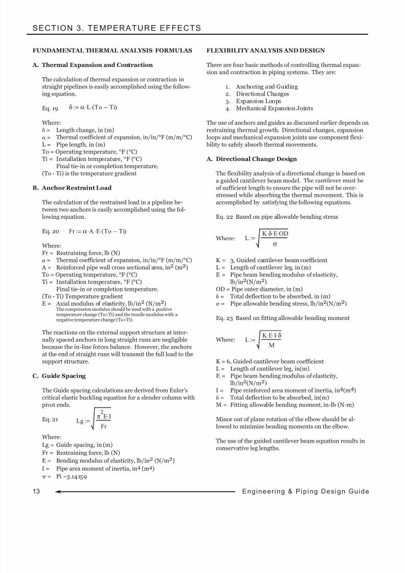
The flexibility analysis of a directional change is based ona guided cantilever beam model. The cantilever must beof sufficient length to ensure the pipe will not be over-stressed while absorbing the thermal movement. This is
accomplished by satisfying the following equations.
Eq. 22 Based on pipe allowable bending stress
Where:
K = 3, Guided cantilever beam coefficientL = Length of cantilever leg, in (m)E = Pipe beam bending modulus of elasticity,
lb/in2(N/m2)OD = Pipe outer diameter, in (m)δ = Total deflection to be absorbed, in (m)σ = Pipe allowable bending stress, lb/in2(N/m2)
Eq. 23 Based on fitting allowable bending moment
Where:
K = 6, Guided cantilever beam coefficientL = Length of cantilever leg, in(m)E = Pipe beam bending modulus of elasticity,
lb/in2(N/m2)I = Pipe reinforced area moment of inertia, in4(m4)δ = Total deflection to be absorbed, in(m)M = Fitting allowable bending moment, in-lb (N-m)
Minor out of plane rotation of the elbow should be al-lowed to minimize bending moments on the elbow.
The use of the guided cantilever beam equation results inconservative leg lengths.
δ α L⋅ To Ti−( )⋅:=
Fr α A⋅ E⋅ To Ti−( )⋅:=
Lg π
2E I⋅
Fr :=
L K E⋅ I⋅ δ⋅
M:=
L K δ⋅ E⋅ OD⋅
σ:=
8/9/2019 Engineering Piping Design Guide Fibra de Vidrio
http://slidepdf.com/reader/full/engineering-piping-design-guide-fibra-de-vidrio 17/36
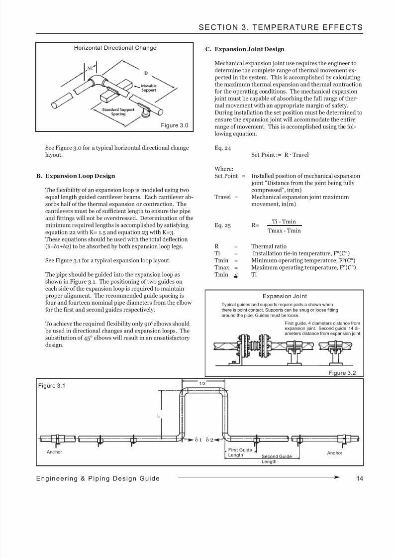
8/9/2019 Engineering Piping Design Guide Fibra de Vidrio
http://slidepdf.com/reader/full/engineering-piping-design-guide-fibra-de-vidrio 18/36
SECTION 3. TEMPERATURE EFFECTS
15 Eng ineer ing & Pip ing Design Gu ide
E x amp l e P r o b l em :
Determine the "Travel" and "Set Point" for the followingconditions.
Ti = 75°F, Tmin = 45°F, Tmax = 145°F, R = 0.3Pipe total thermal movement is 6 inches.
Design factor 1.5
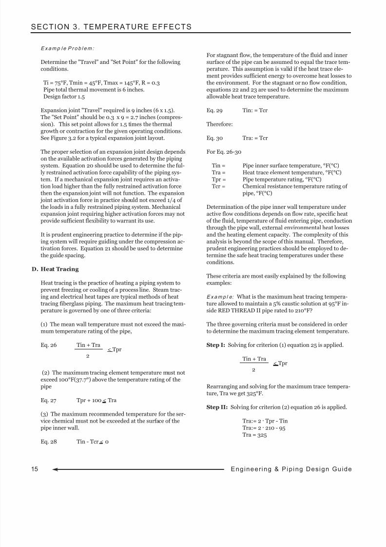
Expansion joint "Travel" required is 9 inches (6 x 1.5).The "Set Point" should be 0.3 x 9 = 2.7 inches (compres-
sion). This set point allows for 1.5 times the thermalgrowth or contraction for the given operating conditions.See Figure 3.2 for a typical expansion joint layout.
The proper selection of an expansion joint design dependson the available activation forces generated by the pipingsystem. Equation 20 should be used to determine the ful-ly restrained activation force capability of the piping sys-tem. If a mechanical expansion joint requires an activa-tion load higher than the fully restrained activation force
then the expansion joint will not function. The expansion joint activation force in practice should not exceed 1/4 of the loads in a fully restrained piping system. Mechanicalexpansion joint requiring higher activation forces may notprovide sufficient flexibility to warrant its use.
It is prudent engineering practice to determine if the pip-ing system will require guiding under the compression ac-tivation forces. Equation 21 should be used to determinethe guide spacing.
D. Heat Tracing
Heat tracing is the practice of heating a piping system to
prevent freezing or cooling of a process line. Steam trac-ing and electrical heat tapes are typical methods of heattracing fiberglass piping. The maximum heat tracing tem-perature is governed by one of three criteria:
(1) The mean wall temperature must not exceed the maxi-mum temperature rating of the pipe,
Eq. 26 Tin + Tra< Tpr
2
(2) The maximum tracing element temperature must notexceed 100°F(37.7°) above the temperature rating of thepipe
Eq. 27 Tpr + 100 < Tra
(3) The maximum recommended temperature for the ser- vice chemical must not be exceeded at the surface of thepipe inner wall.
Eq. 28 Tin - Tcr < 0
For stagnant flow, the temperature of the fluid and innersurface of the pipe can be assumed to equal the trace tem-perature. This assumption is valid if the heat trace ele-ment provides sufficient energy to overcome heat losses tothe environment. For the stagnant or no flow condition,equations 22 and 23 are used to determine the maximum
allowable heat trace temperature.
Eq. 29 Tin: = Tcr
Therefore:
Eq. 30 Tra: = Tcr
For Eq. 26-30
Tin = Pipe inner surface temperature, °F(°C)Tra = Heat trace element temperature, °F(°C)Tpr = Pipe temperature rating, °F(°C)Tcr = Chemical resistance temperature rating of
pipe, °F(°C)
Determination of the pipe inner wall temperature underactive flow conditions depends on flow rate, specific heatof the fluid, temperature of fluid entering pipe, conductionthrough the pipe wall, external environmental heat losses
and the heating element capacity. The complexity of thisanalysis is beyond the scope of this manual. Therefore,prudent engineering practices should be employed to de-termine the safe heat tracing temperatures under theseconditions.
These criteria are most easily explained by the followingexamples:
E x amp l e: What is the maximum heat tracing tempera-ture allowed to maintain a 5% caustic solution at 95°F in-side RED THREAD II pipe rated to 210°F?
The three governing criteria must be considered in orderto determine the maximum tracing element temperature.
Step I: Solving for criterion (1) equation 25 is applied.
Tin + Tra< Tpr
2
Rearranging and solving for the maximum trace tempera-ture, Tra we get 325°F.
Step II: Solving for criterion (2) equation 26 is applied.
Tra:= 2 . Tpr - TinTra:= 2 . 210 - 95Tra = 325
8/9/2019 Engineering Piping Design Guide Fibra de Vidrio
http://slidepdf.com/reader/full/engineering-piping-design-guide-fibra-de-vidrio 19/36
SECTION 3. TEMPERATURE EFFECTS
Rearranging and solving for the maximum trace tempera-ture, Tra we get 310°F.
Tpr + 100 < TraTra = 325
Step III: Solving for criterion (3) equation 29 the stag-
nant flow condition is applied.
Tra:= Tc1
Therefore the maximum allowable heat trace temperatureequals the maximum chemical resistance temperature forthe piping. Referencing Smith Fibercast, Chemical Resistance Guide, Bulletin No. E5615, RED THREAD IIpipe is rated to 100°F in 5% caustic. Therefore the maxi-mum heat trace temperature is 100°F.
However, if the fluid were flowing into the pipeline attemperatures below 100°F, then the heat trace tempera-ture would be higher than 100°F. A thorough heat trans-
fer analysis would be required to determine the appropri-ate heat trace temperature for this condition.
The maximum heat trace temperature for stagnant flow is100°F, the lowest temperature calculated using the threecriteria.
E. Thermal Conductivity - Heat Gain or Los
The thermal conductivity of fiberglass piping is approxi-mately 1/100 that of steel, making it a poor conductor of heat compared to steel. However, the use of insulation toprevent heat loss or gain is recommended when there areeconomic consequences due to heat loss or gain. Typical
fiberglass thermal conductivity values vary from 0.07-0.29 BTU/(Ft.)(Hr.)(°F).
F. Thermal Expansion in Buried Pipe
Soil restraint inherently restrains movement of buriedSmith Fibercast pipelines because these pipes develop rel-atively small forces during a temperature change. Specialprecautions (thrust blocks, guides, expansion joints, etc.)
for handling thermal expansion are not necessary if thepipe is buried at least two to three feet and the beddingmaterial is of a soil type capable of restraining the line.Sand, loam, clay, silt, crushed rock and gravel are suitable bedding for restraining a pipeline; however, special pre-cautions must be taken to properly anchor the pipe inswamps, bogs, etc. where bedding might easily shift and yield to even the low forces developed in fiberglass pipe.
G. Pipe Torque Due to Thermal Expansion
Torsion shear stresses in piping systems containing multi-ple elevation and directional changes normally do nothave to be considered in pipe analysis. The allowable bending moments are much lower than the allowable tor-sional moments in a pipe. Therefore, bending moments in
a pipe leg reacted by torsion in a connecting pipe will belimited by the bending moment capability of the pipe notthe torsional load. Computer modeling is recommendedfor this sophisticated level of piping system analysis.
16Engineer ing & Pip ing Design Guide
8/9/2019 Engineering Piping Design Guide Fibra de Vidrio
http://slidepdf.com/reader/full/engineering-piping-design-guide-fibra-de-vidrio 20/36
17 Eng ineer ing & Pip ing Design Gu ide
SECTION 4. PIPE BURIAL
INTRODUCTION
The guidelines in this section pertain to the design and burialof fiberglass pipe. The structural design process assumes thepipe will receive adequate support in typically encountered
soil conditions. Recommendations for trenching, selecting,placing and compacting backfill will be discussed.
The successful installation depends on all components work-
ing together to form a sound support system. Therefore, oncea pipe is selected, it is of utmost importance to carefully re- view the native soil conditions, select the backfill material andclosely monitor the trenching and installation process.Properly positioned and compacted bedding and backfill re-duces pipe deformations maximizing long-term performanceof a buried pipeline.
Detailed design and installation data for buried fiberglass pip-ing systems may be found in AWWA M45, Manual of Water
Supply Practices, Fiberglass Pipe Design, First Edition.Contact Smith Fibercast applications engineer for detailed burial calculations.
PIPE FLEXIBILITY
The response of fiberglass pipe to burial loads is highly de-pendent on the flexibility of the pipe walls. The best measureof pipe flexibility can be found using the "pipe stiffness" valueas defined and determined by ASTM D2412 tests.
Pipe with pipe stiffness values greater than 72 psi typically re-sist native backfill loads with minimal pipe deformation. Thepipe stiffness of small diameter fiberglass pipe, 1 to 8 inch di-
ameters, typically meets or exceeds 72 psi. Two to three feetof native backfill cover with a soil modulus greater than orequal to 1,000 psi is generally sufficient to protect this catego-ry of pipe from HS-20 vehicular and dead weight soil loads.
Pipe that is buried under concrete or asphalt roadways thatsupport vehicular loads requires less cover. Design data and burial depth recommendation for specific piping can be foundin Smith Fibercast product bulletins and installation hand-
books. Smith Fibercast's Manual No. B2160 contains specialinstallation instructions for UL Listed RED THREAD IIA pip-ing commonly used under pavements.
Pipe with pipe stiffness values less than 72 psi, are consideredflexible and are more susceptible to the effects of poor com-paction or soil conditions. Because of this, larger diameterpiping requires detailed attention during the design and in-stallation of buried pipelines.
BURIAL ANALYSIS
Pipe burial depth calculations are based on Spangler's deflec-tion equation and Von Mise's buckling equation as outlined in AWWA M45. Application of these methods is based on the
assumption that the design values used for bedding, backfilland compaction levels will be achieved with good field prac-tice and appropriate equipment. If these assumptions are notmet, the deflections can be higher or lower than predicted by calculation.
A. Soil Types
A soil's ability to support pipe depends on the type of soil,degree of compaction and condition of the soil, i.e. density and moisture content. A stable soil is capable of providingsufficient long-term bearing resistance to support a buriedpipe. Unstable soils such as peat, organic soil, and highly expansive clays exhibit a significant change in volume
with a change in moisture content. Special trenching and backfill requirements are necessary when the native soil isunstable. Some guidelines to aid the engineer in deter-mining the stability at a particular site follow:
1. For cohesive soils or granular-cohesive soils, if the
unconfined compressive strength per ASTM D2166exceeds 1,500 lb/ft2, the soil will generally be stable.
2. For cohesive soils, if the shear strength of the soilper ASTM D2573 is in excess of 750 lb/ft2, the soil will generally be stable.
3. For sand, if the standard penetration "Blow" value,
N, is above 10, the soil will generally be stable.
Soils types are grouped into "stiffness categories" (SC).They are designated SC1 through SC5. SC1 indicates a soilthat provides the highest soil stiffness at any given Proctordensity. An SC1 classified soil requires the least amountof compaction to achieve the desired soil stiffness. Thehigher numbered soil classifications (SC2-SC4) become,
the more compaction is required to obtain specific soilstiffness at a given Proctor density. The SC5 soils are un-stable and should not be used as backfill or bedding.Decaying organic waste and frozen materials fall in theSC5 category. Lists of recommended backfill materials areshown in Table 4.0.
SECTION 4. Pipe Burial
8/9/2019 Engineering Piping Design Guide Fibra de Vidrio
http://slidepdf.com/reader/full/engineering-piping-design-guide-fibra-de-vidrio 21/36
B. Soil Modulus Considerations
The soil modulus is a common variable that is very impor-tant to fiberglass piping burial analysis regardless of thesoil type. Extensive research and engineering analysis hasshown that a soil modulus of 1,000 psi provides very goodsupport to fiberglass pipe. Table 4.0 shows the degree of compaction based on the Proctor density to obtain a soilmodulus of 1,000 psi. It is worth noting that for all stiff-
ness categories this soil modulus may be obtained, al-though with varying compaction requirements.
Although a modulus of 1,000 psi is preferred, values aslow as 750 psi will provide sufficient support to fiberglasspipe if it is properly engineered and installed.
TRENCH EXCAVATION AND PREPARATION
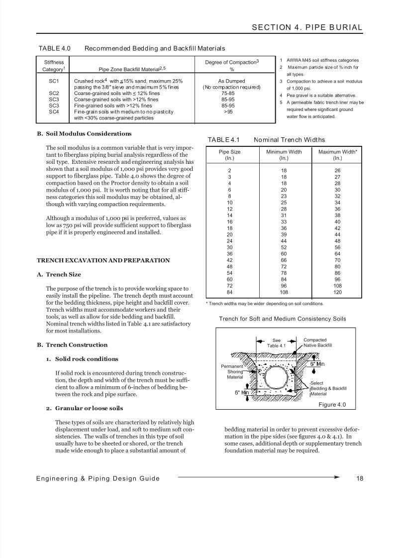
A. Trench Size
The purpose of the trench is to provide working space to
easily install the pipeline. The trench depth must accountfor the bedding thickness, pipe height and backfill cover.Trench widths must accommodate workers and theirtools, as well as allow for side bedding and backfill.Nominal trench widths listed in Table 4.1 are satisfactory for most installations.
B. Trench Construction
1. Solid rock conditions
If solid rock is encountered during trench construc-tion, the depth and width of the trench must be suffi-cient to allow a minimum of 6-inches of bedding be-tween the rock and pipe surface.
2. Granular or loose soils
These types of soils are characterized by relatively highdisplacement under load, and soft to medium soft con-sistencies. The walls of trenches in this type of soilusually have to be sheeted or shored, or the trenchmade wide enough to place a substantial amount of
bedding material in order to prevent excessive defor-mation in the pipe sides (see figures 4.0 & 4.1). Insome cases, additional depth or supplementary trenchfoundation material may be required.
SECTION 4. PIPE B URIAL
Stiffness Degree of Compaction3
Category1 Pipe Zone Backfill Material2,5 %
SC1 Crushed rock4 with <15% sand, maximum 25% As Dumped
passing the 3/8" sieve and maximum 5% fines (No compaction required)
SC2 Coarse-grained soils with < 12% fines 75-85
SC3 Coarse-grained soils with >12% fines 85-95SC3 Fine-grained soils with >12% fines 85-95
SC4 Fine-grain soils with medium to no plasticity >95
with <30% coarse-grained particles
TABLE 4.0 Recommended Bedding and Backfi l l Materials
Pipe Size Minimum Width Maximum Width*
(In.) (In.) (In.)
2 18 26
3 18 27
4 18 28
6 20 30
8 23 3210 25 34
12 28 36
14 31 38
16 33 40
18 36 42
20 39 44
24 44 48
30 52 56
36 60 64
42 66 70
48 72 80
54 78 86
60 84 96
72 96 108
84 108 120
TABLE 4.1 Nominal Trench Widths
Figure 4.0
Trench for Soft and Medium Consistency Soils
1 AWWA M45 soil stiffness categories
2 Maximum particle size of ¾ inch for
all types.
3 Compaction to achieve a soil modulus
of 1,000 psi.
4 Pea gravel is a suitable alternative.5 A permeable fabric trench liner may be
required where significant ground
water flow is anticipated.
* Trench widths may be wider depending on soil conditions.
18Engineer ing & Pip ing Design Guide
Compacted
Native BackfillSee
Table 4.1
Permanent
Shoring
Material
Select
Bedding & Backfill
Material
8/9/2019 Engineering Piping Design Guide Fibra de Vidrio
http://slidepdf.com/reader/full/engineering-piping-design-guide-fibra-de-vidrio 22/36
19 Eng ineer ing & Pip ing Design Gu ide
SECTION 4. PIPE BURIAL
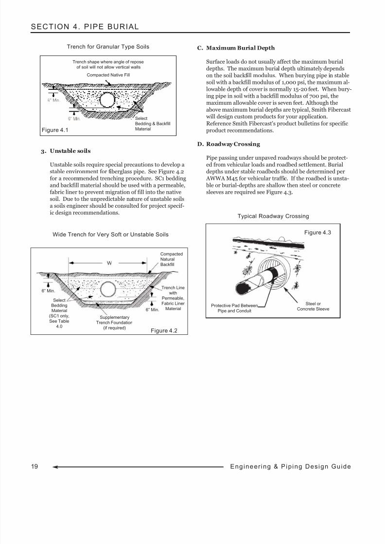
3. Unstable soils
Unstable soils require special precautions to develop astable environment for fiberglass pipe. See Figure 4.2for a recommended trenching procedure. SC1 beddingand backfill material should be used with a permeable,
fabric liner to prevent migration of fill into the nativesoil. Due to the unpredictable nature of unstable soilsa soils engineer should be consulted for project specif-ic design recommendations.
C. Maximum Burial Depth
Surface loads do not usually affect the maximum burialdepths. The maximum burial depth ultimately dependson the soil backfill modulus. When burying pipe in stablesoil with a backfill modulus of 1,000 psi, the maximum al-lowable depth of cover is normally 15-20 feet. When bury-
ing pipe in soil with a backfill modulus of 700 psi, themaximum allowable cover is seven feet. Although theabove maximum burial depths are typical, Smith Fibercast will design custom products for your application.
Reference Smith Fibercast's product bulletins for specificproduct recommendations.
D. Roadway Crossing
Pipe passing under unpaved roadways should be protect-ed from vehicular loads and roadbed settlement. Burialdepths under stable roadbeds should be determined per AWWA M45 for vehicular traffic. If the roadbed is unsta- ble or burial-depths are shallow then steel or concrete
sleeves are required see Figure 4.3.
Trench for Granular Type Soils
Wide Trench for Very Soft or Unstable Soils
Figure 4.1
Supplementary
Trench Foundation
(if required)
Compacted
Natural
Backfill
Figure 4.2
6” Min.
6” Min.
SelectBedding
Material
(SC1 only,
See Table
4.0
Trench Line
with
Permeable,
Fabric Liner
Material
Typical Roadway Crossing
Figure 4.3
Select
Bedding & Backfill
Material
Trench shape where angle of repose
of soil will not allow vertical walls
Compacted Native Fill
Protective Pad Between
Pipe and Conduit
Steel or
Concrete Sleeve
8/9/2019 Engineering Piping Design Guide Fibra de Vidrio
http://slidepdf.com/reader/full/engineering-piping-design-guide-fibra-de-vidrio 23/36
SECTION 4. PIPE B URIAL
BEDDING AND BACKFILL
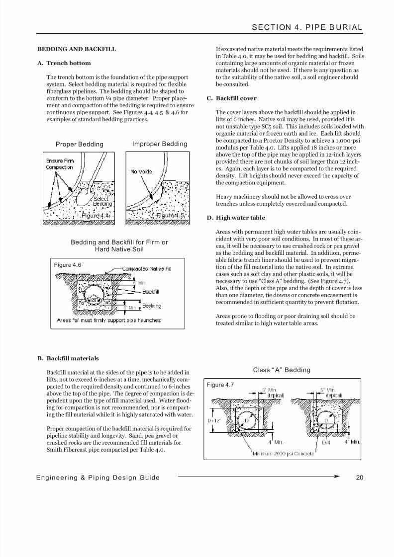
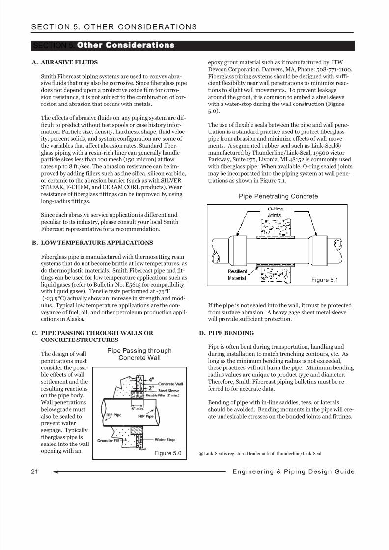
A. Trench bottom
The trench bottom is the foundation of the pipe supportsystem. Select bedding material is required for flexiblefiberglass pipelines. The bedding should be shaped to
conform to the bottom ¼ pipe diameter. Proper place-ment and compaction of the bedding is required to ensurecontinuous pipe support. See Figures 4.4, 4.5 & 4.6 forexamples of standard bedding practices.
B. Backfill materials
Backfill material at the sides of the pipe is to be added inlifts, not to exceed 6-inches at a time, mechanically com-pacted to the required density and continued to 6-inchesabove the top of the pipe. The degree of compaction is de-pendent upon the type of fill material used. Water flood-ing for compaction is not recommended, nor is compact-ing the fill material while it is highly saturated with water.
Proper compaction of the backfill material is required forpipeline stability and longevity. Sand, pea gravel orcrushed rocks are the recommended fill materials forSmith Fibercast pipe compacted per Table 4.0.
If excavated native material meets the requirements listedin Table 4.0, it may be used for bedding and backfill. Soilscontaining large amounts of organic material or frozenmaterials should not be used. If there is any question asto the suitability of the native soil, a soil engineer should be consulted.
C. Backfill cover
The cover layers above the backfill should be applied inlifts of 6 inches. Native soil may be used, provided it is
not unstable type SC5 soil. This includes soils loaded withorganic material or frozen earth and ice. Each lift should be compacted to a Proctor Density to achieve a 1,000-psimodulus per Table 4.0. Lifts applied 18 inches or moreabove the top of the pipe may be applied in 12-inch layersprovided there are not chunks of soil larger than 12 inch-es. Again, each layer is to be compacted to the requireddensity. Lift heights should never exceed the capacity of the compaction equipment.
Heavy machinery should not be allowed to cross overtrenches unless completely covered and compacted.
D. High water table
Areas with permanent high water tables are usually coin-cident with very poor soil conditions. In most of these ar-
eas, it will be necessary to use crushed rock or pea gravelas the bedding and backfill material. In addition, perme-able fabric trench liner should be used to prevent migra-tion of the fill material into the native soil. In extremecases such as soft clay and other plastic soils, it will benecessary to use "Class A" bedding. (See Figure 4.7). Also, if the depth of the pipe and the depth of cover is less
than one diameter, tie downs or concrete encasement isrecommended in sufficient quantity to prevent flotation.
Areas prone to flooding or poor draining soil should betreated similar to high water table areas.
Proper Bedding Improper Bedding
Figure 4.4 Figure 4.5
Figure 4.6
Figure 4.7
Bedding and Backfill for Firm orHard Native Soil
Class “ A” Bedding
20Engineer ing & Pip ing Design Guide
8/9/2019 Engineering Piping Design Guide Fibra de Vidrio
http://slidepdf.com/reader/full/engineering-piping-design-guide-fibra-de-vidrio 24/36
21 Eng ineer ing & Pip ing Design Gu ide
SECTION 5. OTHER CONSIDERATIONS
A. ABRASIVE FLUIDS
Smith Fibercast piping systems are used to convey abra-sive fluids that may also be corrosive. Since fiberglass pipedoes not depend upon a protective oxide film for corro-
sion resistance, it is not subject to the combination of cor-rosion and abrasion that occurs with metals.
The effects of abrasive fluids on any piping system are dif-
ficult to predict without test spools or case history infor-mation. Particle size, density, hardness, shape, fluid veloc-ity, percent solids, and system configuration are some of the variables that affect abrasion rates. Standard fiber-glass piping with a resin-rich liner can generally handleparticle sizes less than 100 mesh (150 micron) at flow rates up to 8 ft./sec. The abrasion resistance can be im-proved by adding fillers such as fine silica, silicon carbide,or ceramic to the abrasion barrier (such as with SILVER STREAK, F-CHEM, and CERAM CORE products). Wear
resistance of fiberglass fittings can be improved by usinglong-radius fittings.
Since each abrasive service application is different andpeculiar to its industry, please consult your local SmithFibercast representative for a recommendation.
B. LOW TEMPERATURE APPLICATIONS
Fiberglass pipe is manufactured with thermosetting resinsystems that do not become brittle at low temperatures, asdo thermoplastic materials. Smith Fibercast pipe and fit-tings can be used for low temperature applications such asliquid gases (refer to Bulletin No. E5615 for compatibility
with liquid gases). Tensile tests performed at -75°F(-23.9°C) actually show an increase in strength and mod-ulus. Typical low temperature applications are the con- veyance of fuel, oil, and other petroleum production appli-cations in Alaska.
C. PIPE PASSING THROUGH WALLS OR CONCRETE STRUCTURES
The design of wallpenetrations mustconsider the possi- ble effects of wallsettlement and theresulting reactionson the pipe body. Wall penetrations below grade mustalso be sealed toprevent waterseepage. Typically fiberglass pipe issealed into the wallopening with an
epoxy grout material such as if manufactured by ITW Devcon Corporation, Danvers, MA, Phone: 508-771-1100.Fiberglass piping systems should be designed with suffi-cient flexibility near wall penetrations to minimize reac-tions to slight wall movements. To prevent leakage
around the grout, it is common to embed a steel sleeve with a water-stop during the wall construction (Figure5.0).
The use of flexible seals between the pipe and wall pene-
tration is a standard practice used to protect fiberglasspipe from abrasion and minimize effects of wall move-ments. A segmented rubber seal such as Link-Seal®manufactured by Thunderline/Link-Seal, 19500 victorParkway, Suite 275, Livonia, MI 48152 is commonly used with fiberglass pipe. When available, O-ring sealed jointsmay be incorporated into the piping system at wall pene-trations as shown in Figure 5.1.
If the pipe is not sealed into the wall, it must be protectedfrom surface abrasion. A heavy gage sheet metal sleeve will provide sufficient protection.
D. PIPE BENDING
Pipe is often bent during transportation, handling and
during installation to match trenching contours, etc. Aslong as the minimum bending radius is not exceeded,these practices will not harm the pipe. Minimum bendingradius values are unique to product type and diameter.Therefore, Smith Fibercast piping bulletins must be re-ferred to for accurate data.
Bending of pipe with in-line saddles, tees, or lateralsshould be avoided. Bending moments in the pipe will cre-ate undesirable stresses on the bonded joints and fittings.
® Link-Seal is registered trademark of Thunderline/Link-Seal
SECTION 5. Other Considerations
Figure 5.0
Figure 5.1
Pipe Passing throughConcrete Wall
Pipe Penetrating Concrete
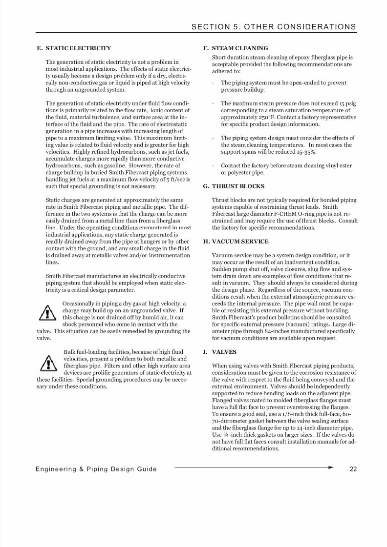
8/9/2019 Engineering Piping Design Guide Fibra de Vidrio
http://slidepdf.com/reader/full/engineering-piping-design-guide-fibra-de-vidrio 25/36
SECTION 5. OTHER CONSIDERATIONS
E. STATIC ELECTRICITY
The generation of static electricity is not a problem inmost industrial applications. The effects of static electrici-ty usually become a design problem only if a dry, electri-cally non-conductive gas or liquid is piped at high velocity through an ungrounded system.
The generation of static electricity under fluid flow condi-tions is primarily related to the flow rate, ionic content of the fluid, material turbulence, and surface area at the in-
terface of the fluid and the pipe. The rate of electrostaticgeneration in a pipe increases with increasing length of pipe to a maximum limiting value. This maximum limit-ing value is related to fluid velocity and is greater for high velocities. Highly refined hydrocarbons, such as jet fuels,accumulate charges more rapidly than more conductivehydrocarbons, such as gasoline. However, the rate of charge buildup in buried Smith Fibercast piping systemshandling jet fuels at a maximum flow velocity of 5 ft/sec issuch that special grounding is not necessary.
Static charges are generated at approximately the samerate in Smith Fibercast piping and metallic pipe. The dif-ference in the two systems is that the charge can be moreeasily drained from a metal line than from a fiberglassline. Under the operating conditions encountered in most
industrial applications, any static charge generated isreadily drained away from the pipe at hangers or by othercontact with the ground, and any small charge in the fluidis drained away at metallic valves and/or instrumentationlines.
Smith Fibercast manufactures an electrically conductivepiping system that should be employed when static elec-
tricity is a critical design parameter.
Occasionally in piping a dry gas at high velocity, acharge may build up on an ungrounded valve. If this charge is not drained off by humid air, it canshock personnel who come in contact with the
valve. This situation can be easily remedied by grounding the valve.
Bulk fuel-loading facilities, because of high fluid velocities, present a problem to both metallic andfiberglass pipe. Filters and other high surface areadevices are prolific generators of static electricity at
these facilities. Special grounding procedures may be neces-sary under these conditions.
F. STEAM CLEANING
Short duration steam cleaning of epoxy fiberglass pipe isacceptable provided the following recommendations are
adhered to:
· The piping system must be open-ended to preventpressure buildup.
· The maximum steam pressure does not exceed 15 psigcorresponding to a steam saturation temperature of approximately 250°F. Contact a factory representativefor specific product design information.
· The piping system design must consider the effects of the steam cleaning temperatures. In most cases thesupport spans will be reduced 15-35%.
· Contact the factory before steam cleaning vinyl esteror polyester pipe.
G. THRUST BLOCKS
Thrust blocks are not typically required for bonded pipingsystems capable of restraining thrust loads. SmithFibercast large diameter F-CHEM O-ring pipe is not re-strained and may require the use of thrust blocks. Consultthe factory for specific recommendations.
H. VACUUM SERVICE
Vacuum service may be a system design condition, or itmay occur as the result of an inadvertent condition.Sudden pump shut off, valve closures, slug flow and sys-tem drain down are examples of flow conditions that re-sult in vacuum. They should always be considered during
the design phase. Regardless of the source, vacuum con-ditions result when the external atmospheric pressure ex-ceeds the internal pressure. The pipe wall must be capa- ble of resisting this external pressure without buckling.Smith Fibercast's product bulletins should be consultedfor specific external pressure (vacuum) ratings. Large di-ameter pipe through 84-inches manufactured specifically for vacuum conditions are available upon request.
I. VALVES
When using valves with Smith Fibercast piping products,consideration must be given to the corrosion resistance of the valve with respect to the fluid being conveyed and theexternal environment. Valves should be independently supported to reduce bending loads on the adjacent pipe.Flanged valves mated to molded fiberglass flanges musthave a full flat face to prevent overstressing the flanges.To ensure a good seal, use a 1/8-inch thick full-face, 60-70-durometer gasket between the valve sealing surfaceand the fiberglass flange for up to 14-inch diameter pipe.Use ¼-inch thick gaskets on larger sizes. If the valves donot have full flat faces consult installation manuals for ad-ditional recommendations.
22Engineer ing & Pip ing Design Guide
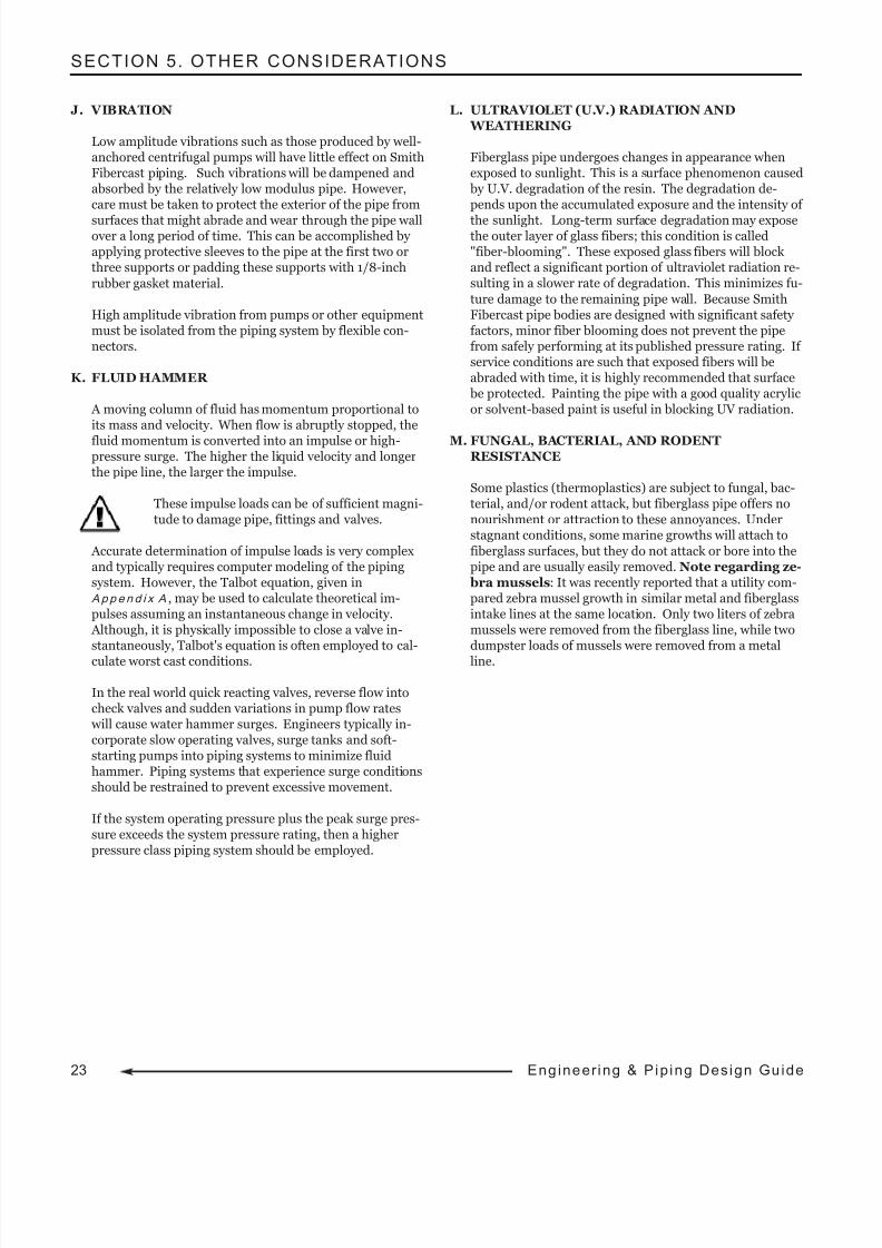
8/9/2019 Engineering Piping Design Guide Fibra de Vidrio
http://slidepdf.com/reader/full/engineering-piping-design-guide-fibra-de-vidrio 26/36
23 Eng ineer ing & Pip ing Design Gu ide
SECTION 5. OTHER CONSIDERATIONS
J. VIBRATION
Low amplitude vibrations such as those produced by well-anchored centrifugal pumps will have little effect on SmithFibercast piping. Such vibrations will be dampened andabsorbed by the relatively low modulus pipe. However,care must be taken to protect the exterior of the pipe from
surfaces that might abrade and wear through the pipe wallover a long period of time. This can be accomplished by applying protective sleeves to the pipe at the first two orthree supports or padding these supports with 1/8-inch
rubber gasket material.
High amplitude vibration from pumps or other equipmentmust be isolated from the piping system by flexible con-nectors.
K. FLUID HAMMER
A moving column of fluid has momentum proportional toits mass and velocity. When flow is abruptly stopped, the
fluid momentum is converted into an impulse or high-pressure surge. The higher the liquid velocity and longerthe pipe line, the larger the impulse.
These impulse loads can be of sufficient magni-tude to damage pipe, fittings and valves.
Accurate determination of impulse loads is very complexand typically requires computer modeling of the pipingsystem. However, the Talbot equation, given inAppe n d i x A , may be used to calculate theoretical im-pulses assuming an instantaneous change in velocity. Although, it is physically impossible to close a valve in-stantaneously, Talbot's equation is often employed to cal-
culate worst cast conditions.
In the real world quick reacting valves, reverse flow intocheck valves and sudden variations in pump flow rates will cause water hammer surges. Engineers typically in-corporate slow operating valves, surge tanks and soft-starting pumps into piping systems to minimize fluidhammer. Piping systems that experience surge conditionsshould be restrained to prevent excessive movement.
If the system operating pressure plus the peak surge pres-sure exceeds the system pressure rating, then a higherpressure class piping system should be employed.
L. ULTRAVIOLET (U.V.) RADIATION AND WEATHERING
Fiberglass pipe undergoes changes in appearance whenexposed to sunlight. This is a surface phenomenon caused by U.V. degradation of the resin. The degradation de-pends upon the accumulated exposure and the intensity of
the sunlight. Long-term surface degradation may exposethe outer layer of glass fibers; this condition is called"fiber-blooming". These exposed glass fibers will block and reflect a significant portion of ultraviolet radiation re-sulting in a slower rate of degradation. This minimizes fu-
ture damage to the remaining pipe wall. Because SmithFibercast pipe bodies are designed with significant safety factors, minor fiber blooming does not prevent the pipefrom safely performing at its published pressure rating. If service conditions are such that exposed fibers will beabraded with time, it is highly recommended that surface be protected. Painting the pipe with a good quality acrylicor solvent-based paint is useful in blocking UV radiation.
M. FUNGAL, BACTERIAL, AND RODENTRESISTANCE
Some plastics (thermoplastics) are subject to fungal, bac-terial, and/or rodent attack, but fiberglass pipe offers nonourishment or attraction to these annoyances. Understagnant conditions, some marine growths will attach to
fiberglass surfaces, but they do not attack or bore into thepipe and are usually easily removed. Note regarding ze-
bra mussels: It was recently reported that a utility com-pared zebra mussel growth in similar metal and fiberglassintake lines at the same location. Only two liters of zebramussels were removed from the fiberglass line, while twodumpster loads of mussels were removed from a metal
line.
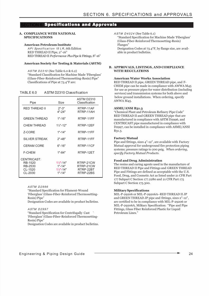
8/9/2019 Engineering Piping Design Guide Fibra de Vidrio
http://slidepdf.com/reader/full/engineering-piping-design-guide-fibra-de-vidrio 27/36
SECTION 6. SPECIFICATIONS and APPROVALS
A. COMPLIANCE WITH NATIONALSPECIFICATIONS
American Petroleum InstituteAP I Speci f i c a t i o n 15 LR , 6th Edition
RED THREAD II Pipe, 2"-16"RED THREAD II Performance PlusPipe & Fittings, 8"-16"
American Society for Testing & Materials (ASTM)
ASTM D2310 (See Table 6.0 & 6.2)“Standard Classification for Machine Made ‘Fiberglass’(Glass-Fiber-Reinforced Thermosetting-Resin) Pipe”Classifications of Pipe at 73.4°F are:
ASTM D299 6
“Standard Specification for Filament-Wound‘Fiberglass’ (Glass-Fiber-Reinforced Thermosetting-Resin) Pipe”Designation Codes are available in product bulletins.
ASTM D299 7
“Standard Specification for Centrifugally Cast `‘Fiberglass’ (Glass-Fiber-Reinforced Thermosetting-Resin) Pipe”Designation Codes are available in product bulletins.
ASTM D 4 0 2 4 (See Table 6.1)“Standard Specification for Machine Made ‘Fiberglass’(Glass-Fiber-Reinforced Thermosetting-Resin)Flanges”Designation Codes at 73.4°F, by flange size, are avail-
able in product bulletins.
B. APPROVALS, LISTINGS, AND COMPLIANCE WITH REGULATIONS
American Water Works AssociationRED THREAD II pipe, GREEN THREAD pipe, and F-CHEM pipe can be made in compliance with AWWA M45for use as pressure pipes for water distribution (includingservices) and transmission systems for both above and below ground installations. When ordering, specify AWWA M45.
ASME/ANSI B31.3“Chemical Plant and Petroleum Refinery Pipe Code”RED THREAD II and GREEN THREAD pipe that aremanufactured in compliance with ASTM D2996, andCENTRICAST pipe manufactured in compliance withD2997, can be installed in compliance with ASME/ANSI
B31.3.
Factory MutualPipe and fittings, sizes 4"-12", are available with Factory Mutual approval for underground fire protection pipingsystems; pressure ratings to 200 psig. When ordering,specify Factory Mutual Products.
Food and Drug AdministrationThe resins and curing agents used in the manufacture of RED THREAD II Pipe and Fittings and GREEN THREADPipe and Fittings are defined as acceptable with the U.S.Food, Drug, and Cosmetic Act as listed under 21 CFR Part177 Subpart C Section 177.2280 and 21 CFR Part 175Subpart C Section 175.300.
Military SpecificationsMIL-P-29206 or MIL-P-29206A–RED THREAD II JPand GREEN THREAD JP pipe and fittings, sizes 2"-12",are certified to be in compliance with MIL-P-29206 orMIL-P-29206A, Military Specification: “Pipe and PipeFittings, Glass Fiber Reinforced Plastic for LiquidPetroleum Lines.”
SECTION 6. Specifications and Approvals
ASTM D2310
Pipe Size ClassificationRED THREAD II 2"-3" RTRP-11AF
4"-24" RTRP-11AH
GREEN THREAD 1"-16" RTRP-11FF
CHEM THREAD 11/2"-12" RTRP-12EF
Z-CORE 1"-14" RTRP-11FF
SILVER STREAK 2"-48" RTRP-11FF
CERAM CORE 6"-16" RTRP-11CF
F-CHEM 1"-84" RTRP-12ET
CENTRICAST:RB-1520 11/2"-14" RTRP-21CWRB-2530 1"-14" RTRP-21CWCL-1520 11/2"-14" RTRP-22BTCL-2030 1"-14" RTRP-22BS
TABLE 6.0 ASTM D2310 Classi ficat ion
24Engineer ing & Pip ing Design Guide
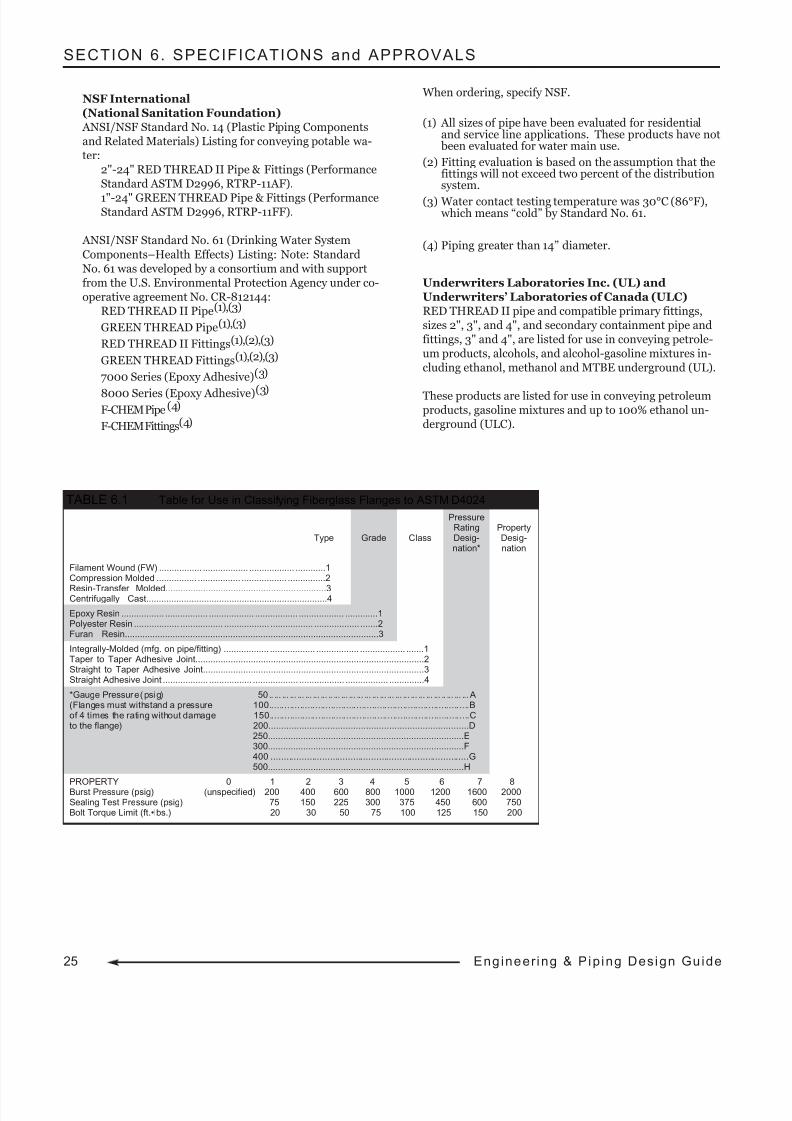
8/9/2019 Engineering Piping Design Guide Fibra de Vidrio
http://slidepdf.com/reader/full/engineering-piping-design-guide-fibra-de-vidrio 28/36
SECTION 6. SPECIFICATIONS and APPROVALS
NSF International(National Sanitation Foundation) ANSI/NSF Standard No. 14 (Plastic Piping Componentsand Related Materials) Listing for conveying potable wa-ter:
2"-24" RED THREAD II Pipe & Fittings (PerformanceStandard ASTM D2996, RTRP-11AF).
1"-24" GREEN THREAD Pipe & Fittings (PerformanceStandard ASTM D2996, RTRP-11FF).
ANSI/NSF Standard No. 61 (Drinking Water System
Components–Health Effects) Listing: Note: StandardNo. 61 was developed by a consortium and with supportfrom the U.S. Environmental Protection Agency under co-operative agreement No. CR-812144:
RED THREAD II Pipe(1),(3)
GREEN THREAD Pipe(1),(3)
RED THREAD II Fittings(1),(2),(3)
GREEN THREAD Fittings(1),(2),(3)
7000 Series (Epoxy Adhesive)(3)
8000 Series (Epoxy Adhesive)(3)F-CHEM Pipe(4)
F-CHEM Fittings(4)
When ordering, specify NSF.
(1) All sizes of pipe have been evaluated for residentialand service line applications. These products have not been evaluated for water main use.
(2) Fitting evaluation is based on the assumption that thefittings will not exceed two percent of the distributionsystem.
(3) Water contact testing temperature was 30°C (86°F), which means “cold” by Standard No. 61.
(4) Piping greater than 14” diameter.
Underwriters Laboratories Inc. (UL) andUnderwriters’ Laboratories of Canada (ULC)RED THREAD II pipe and compatible primary fittings,sizes 2", 3", and 4", and secondary containment pipe andfittings, 3" and 4", are listed for use in conveying petrole-um products, alcohols, and alcohol-gasoline mixtures in-cluding ethanol, methanol and MTBE underground (UL).
These products are listed for use in conveying petroleumproducts, gasoline mixtures and up to 100% ethanol un-derground (ULC).
PressureRating Property
Type Grade Class Desig- Desig-nation* nation
Filament Wound (FW) ................. .................. .................. ............1Compression Molded ................ ................. .................. ...............2
Resin-Transfer Molded................................................................3Centrifugally Cast........................................................................4
Epoxy Resin ................. ................. .................. ................. .................. .............1Polyester Resin .................. ................. .................. ................. .................. .......2Furan Resin.....................................................................................................3
Integrally-Molded (mfg. on pipe/fitting) .................. .................. ................. .................. .......1Taper to Taper Adhesive Joint...........................................................................................2Straight to Taper Adhesive Joint........................................................................................3Straight Adhesive Joint .................. ................. .................. .................. ................. ..............4
*Gauge Pressure (psig) 50 .. ... ... ... ... ... ... ... .. ... ... ... ... ... ... ... ... ... ... ... ... ... ... .. ... ... ...A(Flanges must withstand a pressure 100..............................................................................Bof 4 times the rating without damage 150..............................................................................Cto the flange) 200..............................................................................D
250..............................................................................E300..............................................................................F400 .............................................................................G500..............................................................................H
PROPERTY 0 1 2 3 4 5 6 7 8Burst Pressure (psig) (unspecified) 200 400 600 800 1000 1200 1600 2000Sealing Test Pressure (psig) 75 150 225 300 375 450 600 750Bolt Torque Limit (ft.•lbs.) 20 30 50 75 100 125 150 200
TABLE 6.1 Table for Use in Classifying Fiberglass Flanges to ASTM D4024
25 Eng ineer ing & Pip ing Design Gu ide
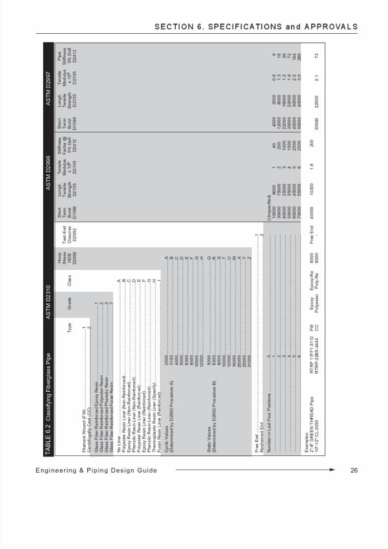
8/9/2019 Engineering Piping Design Guide Fibra de Vidrio
http://slidepdf.com/reader/full/engineering-piping-design-guide-fibra-de-vidrio 29/36
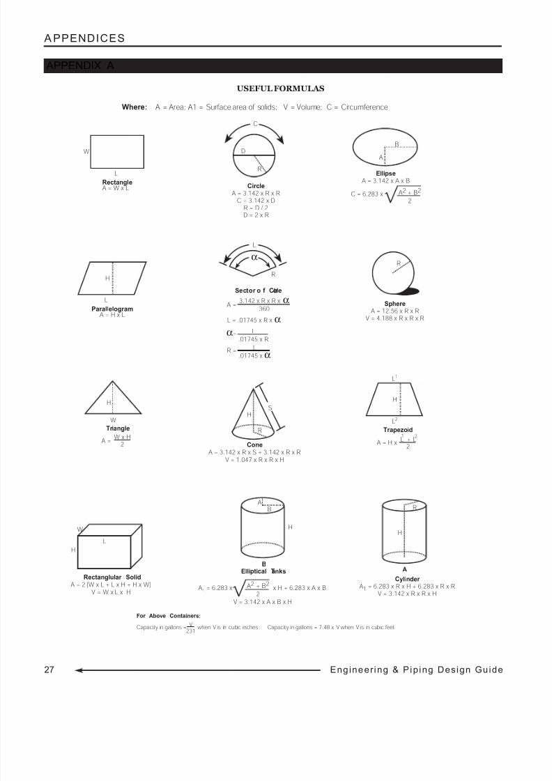
8/9/2019 Engineering Piping Design Guide Fibra de Vidrio
http://slidepdf.com/reader/full/engineering-piping-design-guide-fibra-de-vidrio 30/36
27 Eng ineer ing & Pip ing Design Gu ide
A PPENDICES
USEFUL FORMULAS
APPENDIX A
SphereA = 12.56 x R x R
V = 4.188 x R x R x R
R
W
L
Rectanglular SolidA = 2 [W x L + L x H + H x W]
V = W x L x H
H
H
R
S
ConeA = 3.142 x R x S + 3.142 x R x R
V = 1.047 x R x R x H
B
A
EllipseA = 3.142 x A x B
A2 + B2
2C = 6.283 x
C
D
R
CircleA = 3.142 x R x R
C = 3.142 x DR = D / 2D = 2 x R
For Above Container s:
Capacity in gallons = when V is in cubic inches Capacity in gallons = 7.48 x V when V is in cubic feetV231
Where: A = Area; A1 = Surface area of solids; V = Volume; C = Circumference
W
L
RectangleA = W x L
L
ParallelogramA = H x L
H
A = H xL + L
2
L
Trapezoid
H
2
L1
21
Tr iangle
H
W
W x H2
A =
L
L = .01745 x R x α
α
3.142 x R x R x α360
Sector o f Cir cle
L.01745 x R
L.01745 x α
A =
α=
R =
R
B
V = 3.142 x A x B x H
A1 = 6.283 x A2 + B2
2x H + 6.283 x A x B
H
AB
Elliptical Tanks
H
R
Cylinder A1 = 6.283 x R x H + 6.283 x R x R
V = 3.142 x R x R x H
A
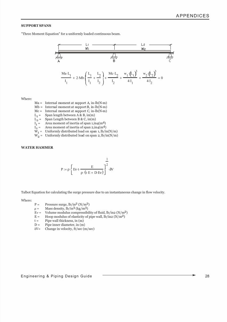
8/9/2019 Engineering Piping Design Guide Fibra de Vidrio
http://slidepdf.com/reader/full/engineering-piping-design-guide-fibra-de-vidrio 31/36
A PPENDICES
SUPPORT SPANS
"Three Moment Equation" for a uniformly loaded continuous beam.
Where:Ma = Internal moment at support A, in-lb(N-m)Mb = Internal moment at support B, in-lb(N-m)Mc = Internal moment at support C, in-lb(N-m)L1 = Span length between A & B, in(m)L2 = Span Length between B & C, in(m)I1 = Area moment of inertia of span 1,in4(m4)I2 = Area moment of inertia of span 2,in4(m4) W 1 = Uniformly distributed load on span 1, lb/in(N/m) W 2 = Uniformly distributed load on span 2, lb/in(N/m)
WATER HAMMER
Talbot Equation for calculating the surge pressure due to an instantaneous change in flow velocity.
Where:P = Pressure surge, lb/in2 (N/m2)ρ = Mass density, lb/in3 (kg/m3)Eν = Volume modulus compressibility of fluid, lb/in2 (N/m2)E = Hoop modulus of elasticity of pipe wall, lb/in2 (N/m2)t = Pipe wall thickness, in (m)
D = Pipe inner diameter, in (m)δ V= Change in velocity, ft/sec (m/sec)
Ma L1
⋅
I1
2 Mb⋅L
1
I1
L2
I2
+
⋅+
Mc L2
⋅
I2
+w
1 L
1( )3⋅
4 I1
⋅+
w2
L2( )3
⋅
4 I2
⋅+ 0=
P ρ E ν t⋅ E
ρ t E⋅ D E ν⋅+( )⋅⋅
1
2
⋅ δV⋅:=
28Engineer ing & Pip ing Design Guide
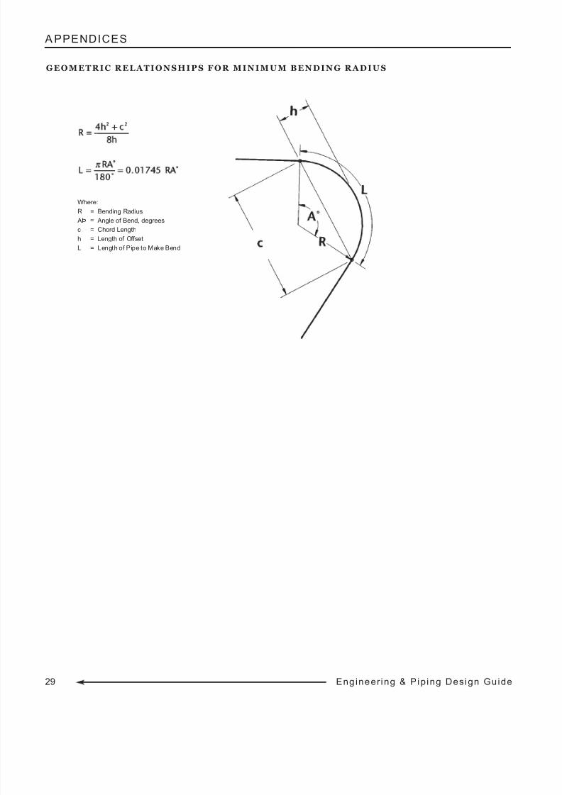
8/9/2019 Engineering Piping Design Guide Fibra de Vidrio
http://slidepdf.com/reader/full/engineering-piping-design-guide-fibra-de-vidrio 32/36
29 Eng ineer ing & Pip ing Design Gu ide
A PPENDICES
G E O M E T R I C R E L A T I O N S H I P S F O R M I N I M U M B E N D I N G R A D I U S
Where:
R = Bending Radius
AÞ = Angle of Bend, degrees
c = Chord Length
h = Length of Offset
L = Length of Pipe to Make Bend
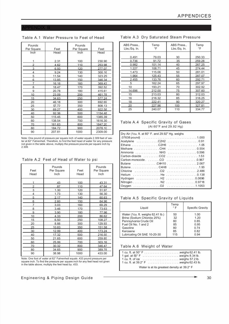
8/9/2019 Engineering Piping Design Guide Fibra de Vidrio
http://slidepdf.com/reader/full/engineering-piping-design-guide-fibra-de-vidrio 33/36
Table A.1 Water Pressu re to Feet of Head
Pounds Pounds
Per Square Feet Per Square Feet
Inch Head Inch Head
1 2.31 100 230.90
2 4.62 110 253.98
3 6.93 120 277.07
4 9.24 130 300.16
5 11.54 140 323.25
6 13.85 150 346.34
7 16.16 160 369.43
8 18.47 170 392.52
9 20.78 180 415.61
10 23.09 200 461.78
15 34.63 250 577.24
20 46.18 300 692.69
25 57.72 350 808.13
30 69.27 400 922.58
40 92.36 500 1154.4850 115.45 600 1385.39
60 138.54 700 1616.30
70 161.63 800 1847.20
80 184.72 900 2078.10
90 207.81 1000 2309.00
Note: One pound of pressure per square inch of water equals 2.309 feet of wa-ter at 62° Fahrenheit. Therefore, to f ind the feet head of water for any pressurenot given in the table above, multiply the pressure pounds per square inch by2.309.
Table A.3 Dry Saturated Steam Pressure
ABS Press., Temp ABS Press., Temp
Lbs./Sq. In. °F Lbs./Sq. In. °F
0.491 79.03 30 250.330.736 91.72 35 259.28
0.982 101.14 40 267.25
1.227 108.71 45 274.44
1.473 115.06 50 281.01
1.964 125.43 55 287.07
2.455 133.76 60 292.71
5 162.24 65 297.97
10 193.21 70 302.92
14.696 212.00 75 307.60
15 213.03 80 312.03
16 216.32 85 316.25
18 222.41 90 320.27
20 227.96 100 327.81
25 240.07 110 334.77
Pounds Pounds
Feet Per Square Feet Per SquareHead Inch Head Inch
1 .43 100 43.31
2 .87 110 47.64
3 1.30 120 51.97
4 1.73 130 56.30
5 2.17 140 60.63
6 2.60 150 64.96
7 3.03 160 69.29
8 3.46 170 73.63
9 3.90 180 77.96
10 4.33 200 86.62
15 6.50 250 108.27
20 8.66 300 129.93
25 10.83 350 151.5830 12.99 400 173.24
40 17.32 500 216.55
50 21.65 600 259.85
60 25.99 700 303.16
70 30.32 800 346.47
80 34.65 900 389.78
90 38.98 1000 433.00
Table A.2 Feet of Head of Water to psi
Note: One foot of water at 62° Fahrenheit equals .433 pound pressure per square inch. To find the pressure per square inch for any feet head not givenin the table above, multiply the feet head by .433.
Dry Air (1cu. ft. at 60° F. and 29.92" Hg. weighs
.07638 pound) . . . . . . . . . . . . . . . . . . . . . . . . . . . . . . . . 1.000
Acetylene . . . . . . . . . . . . .C2H2 . . . . . . . . . . . . . . . . . . 0.91
Ethane . . . . . . . . . . . . . . . .C2H6 . . . . . . . . . . . . . . . . . .1.05
Methane . . . . . . . . . . . . . . . CH4 . . . . . . . . . . . . . . . . . 0.554
Ammonia . . . . . . . . . . . . . . NH3 . . . . . . . . . . . . . . . . . 0.596
Carbon-dioxide . . . . . . . . . CO2 . . . . . . . . . . . . . . . . . . .1.53
Carbon-monoxide . . . . . . . .CO . . . . . . . . . . . . . . . . . .0.967
Butane . . . . . . . . . . . . . .C4H10 . . . . . . . . . . . . . . . . . 2.067
Butene . . . . . . . . . . . . . . . . C4H8 . . . . . . . . . . . . . . . . . .1.93
Chlorine . . . . . . . . . . . . . . .Cl2 . . . . . . . . . . . . . . . . . .2.486Helium . . . . . . . . . . . . . . . . He . . . . . . . . . . . . . . . . . . 0.138
Hydrogen . . . . . . . . . . . . . . H2 . . . . . . . . . . . . . . . . . 0.0696
Nitrogen . . . . . . . . . . . . . . . . N2 . . . . . . . . . . . . . . . . . 0.9718
Oxygen . . . . . . . . . . . . . . . .O2 . . . . . . . . . . . . . . . . .1.1053
Table A.4 Specif ic Gravity of Gases(At 60°F and 29.92 Hg)
Table A.5 Speci f ic Gravi ty of Liquids
Table A.6 Weight of Water
1 cu. ft. at 50° F . . . . . . . . . . . . . . . . . . . . .weighs 62.41 lb.1 gal. at 50° F . . . . . . . . . . . . . . . . . . . . . .weighs 8.34 lb.1 cu. ft. of ice . . . . . . . . . . . . . . . . . . . . . .weighs 57.2 lb.1 cu. ft. at 39.2° F . . . . . . . . . . . . . . . . . . .weighs 62.43 lb.
Water is at its greatest density at 39.2° F
TempLiquid ° F Specific Gravity
Water (1cu. ft. weighs 62.41 lb.) 50 1.00Brine (Sodium Chloride 25%) 32 1.20Pennsylvania Crude Oil 80 0.85Fuel Oil No. 1 and 2 85 0.95
Gasoline 80 0.74Kerosene 85 0.82Lubricating Oil SAE 10-20-30 115 0.94
APPENDIX B
30Engineer ing & Pip ing Design Guide
A PPENDICES
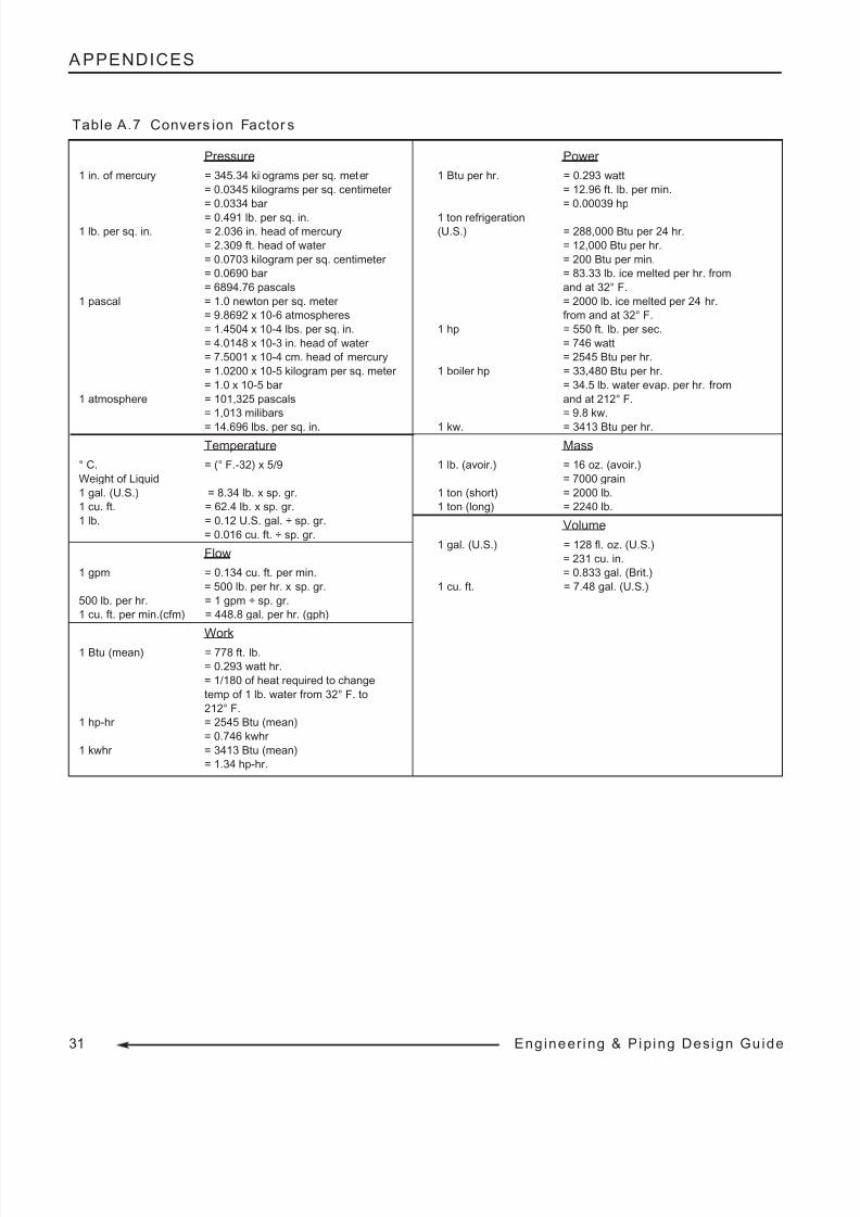
8/9/2019 Engineering Piping Design Guide Fibra de Vidrio
http://slidepdf.com/reader/full/engineering-piping-design-guide-fibra-de-vidrio 34/36
31 Eng ineer ing & Pip ing Design Gu ide
A PPENDICES
Pressure
1 in. of mercury = 345.34 kilograms per sq. meter
= 0.0345 kilograms per sq. centimeter
= 0.0334 bar
= 0.491 lb. per sq. in.
1 lb. per sq. in. = 2.036 in. head of mercury
= 2.309 ft. head of water
= 0.0703 kilogram per sq. centimeter
= 0.0690 bar
= 6894.76 pascals
1 pascal = 1.0 newton per sq. meter
= 9.8692 x 10⁻⁶ atmospheres
= 1.4504 x 10⁻⁴ lbs. per sq. in.
= 4.0148 x 10⁻³ in. head of water
= 7.5001 x 10⁻⁴ cm. head of mercury
= 1.0200 x 10⁻⁵ kilogram per sq. meter
= 1.0 x 10⁻⁵ bar
1 atmosphere = 101,325 pascals
= 1,013 milibars
= 14.696 lbs. per sq. in.
Temperature
° C. = (° F.-32) x 5/9
Weight of Liquid
1 gal. (U.S.) = 8.34 lb. x sp. gr.
1 cu. ft. = 62.4 lb. x sp. gr.
1 lb. = 0.12 U.S. gal. ÷ sp. gr.
= 0.016 cu. ft. ÷ sp. gr.
Flow
1 gpm = 0.134 cu. ft. per min.
= 500 lb. per hr. x sp. gr.
500 lb. per hr. = 1 gpm ÷ sp. gr.
1 cu. ft. per min.(cfm) = 448.8 gal. per hr. (gph)
Work1 Btu (mean) = 778 ft. lb.
= 0.293 watt hr.
= 1/180 of heat required to change
temp of 1 lb. water from 32° F. to
212° F.
1 hp-hr = 2545 Btu (mean)
= 0.746 kwhr
1 kwhr = 3413 Btu (mean)
= 1.34 hp-hr.
Power
1 Btu per hr. = 0.293 watt
= 12.96 ft. lb. per min.
= 0.00039 hp
1 ton refrigeration
(U.S.) = 288,000 Btu per 24 hr.
= 12,000 Btu per hr.
= 200 Btu per min.
= 83.33 lb. ice melted per hr. from
and at 32° F.
= 2000 lb. ice melted per 24 hr.
from and at 32° F.
1 hp = 550 ft. lb. per sec.
= 746 watt
= 2545 Btu per hr.
1 boiler hp = 33,480 Btu per hr.
= 34.5 lb. water evap. per hr. from
and at 212° F.
= 9.8 kw.
1 kw. = 3413 Btu per hr.
Mass
1 lb. (avoir.) = 16 oz. (avoir.)
= 7000 grain
1 ton (short) = 2000 lb.
1 ton (long) = 2240 lb.
Volume
1 gal. (U.S.) = 128 fl. oz. (U.S.)
= 231 cu. in.
= 0.833 gal. (Brit.)
1 cu. ft. = 7.48 gal. (U.S.)
Table A.7 Convers ion Factor s

8/9/2019 Engineering Piping Design Guide Fibra de Vidrio
http://slidepdf.com/reader/full/engineering-piping-design-guide-fibra-de-vidrio 35/36
NOTES
32Engineer ing & Pip ing Design Guide
8/9/2019 Engineering Piping Design Guide Fibra de Vidrio
http://slidepdf.com/reader/full/engineering-piping-design-guide-fibra-de-vidrio 36/36
SMITH FIBERCAST DIVISION
2700 West 65th Street • Little Rock, AR 72209
(501) 568-4010 • Fax: (501) 568-4465
P.O. Box 968 • 25 South Main • Sand Springs, OK 74063
(800) 331-4406 or (918) 245-6651 • Fax: (Local/International) (918) 245-7566 • Fax: (800) 365-7473
ENGINEERING & PIPING DESIGN GUIDE