Embed Size (px)
Citation preview
IPS-E-TP-760
This Standard is the property of Iranian Ministry of Petroleum. All rights are reserved to the owner. Neither whole nor any part of this document may be disclosed to any third party, reproduced, stored in any retrieval system or transmitted in any form or by any means without the prior written consent of the Iranian Ministry of Petroleum.
ENGINEERING STANDARD
FOR
CORROSION CONSIDERATION IN DESIGN
ORIGINAL EDITION
DEC. 1997
This standard specification is reviewed and updated by the relevant technical committee on July 2005. The approved modifications are included in the present issue of IPS.
Dec. 1997
IPS-E-TP-760
1
CONTENTS : PAGE No.
1. SCOPE ............................................................................................................................................ 3 2. REFERENCES ................................................................................................................................ 3 3. DEFINITIONS AND TERMINOLOGY ............................................................................................. 4 4. UNITS ............................................................................................................................................ 10 5. CORROSION PROBLEMS IN PETROLEUM REFINING AND PETROCHEMICAL OPERATION..................................................................................................... 10
5.1 General ................................................................................................................................... 10 5.2 Low Temperature Corrosion ................................................................................................ 10 5.3 High Temperature Corrosion ............................................................................................... 15 5.4 SCC and Embrittlement ........................................................................................................ 26 5.5 Hydrogen Damage ................................................................................................................ 32 5.6 Hydrogen Attack ................................................................................................................... 35 5.7 Corrosion Fatigue ................................................................................................................. 38 5.8 Liquid-Metal Embrittlement.................................................................................................. 38 5.9 Erosion-Corrosion ................................................................................................................ 40 5.10 Corrosion Control ............................................................................................................... 41
6. SYSTEMATIC ANALYSIS OF PROJECT .................................................................................... 41 6.1 General ................................................................................................................................... 41 6.2 Organization of Work............................................................................................................ 42 6.3 Team Work ............................................................................................................................. 43 6.4 Sources of Information......................................................................................................... 47
7. COMPATIBILITY........................................................................................................................... 52 7.1 General ................................................................................................................................... 52 7.2 Requirement .......................................................................................................................... 52
8. SHAPE OR GEOMETRY .............................................................................................................. 62 8.1 General ................................................................................................................................... 62 8.2 Requirement .......................................................................................................................... 62
9. MECHANICS................................................................................................................................. 63 9.1 General ................................................................................................................................... 63 9.2 Requirements ........................................................................................................................ 64
10. SURFACE ................................................................................................................................... 70 10.1 General ................................................................................................................................. 70 10.2 Requirements ...................................................................................................................... 70
11. PROTECTION ............................................................................................................................. 78 11.1 General ................................................................................................................................. 78 11.2 Requirements ...................................................................................................................... 78
12. MAINTAINABILITY ..................................................................................................................... 91 12.1 General ................................................................................................................................. 91 12.2 Requirements ...................................................................................................................... 92
13. ECONOMICS .............................................................................................................................. 93 13.1 General ................................................................................................................................. 93 13.2 Requirements ...................................................................................................................... 93 13.3 Methods of Appraisal.......................................................................................................... 98

Dec. 1997
IPS-E-TP-760
2
APPENDICES :
APPENDIX A COMPATIBILITY ..................................................................................................... 99 APPENDIX B SHAPE OR GEOMETRY ....................................................................................... 125 APPENDIX C MECHANICS.......................................................................................................... 146 APPENDIX D SURFACES............................................................................................................ 165 APPENDIX E PROTECTION ........................................................................................................ 180 APPENDIX F MAINTAINABILITY ................................................................................................ 208 APPENDIX G ECONOMICS ......................................................................................................... 212 APPENDIX I FORMS OF CORROSION AND PREVENTIVE MEASURES ................................ 216
Dec. 1997
IPS-E-TP-760
3
1. SCOPE
This Engineering Standard contains the minimum requirements to be considered in design in order to prevent or control corrosion damage economically and safely in Petroleum Industries.
Factors influencing the service life of materials, design, source of construction materials, fabrication, quality control, specifications, operation, maintenance, environmental conditions, geometry and surface protections are described and presented in this Standard.
The designers are urged to apply this Standard during the design stage in order to avoid or minimize corrosion hazards technically, economically and safely, because proper corrosion control of structures and units is most effectively and economically begun during the design stage.
Basic forms of Corrosion and the Prevention methods are discussed in Appendix I in order to be Considered during the design stages and help the parties involved to analyze the project regarding the Corrosion.
Note:
This standard specification is reviewed and updated by the relevant technical committee on July 2005. The approved modifications by T.C. were sent to IPS users as amendment No. 1 by circular No. 313 on July 2005. These modifications are included in the present issue of IPS.
2. REFERENCES
Throughout this Standard the following dated and undated standards/codes are referred to. These referenced documents shall, to the extent specified herein, form a part of this standard. For dated references, the edition cited applies. The applicability of changes in dated references that occur after the cited date shall be mutually agreed upon by the Company and the Vendor. For undated references, the latest edition of the referenced documents (including any supplements and amendments) applies.
API (AMERICAN PETROLEUM INSTITUTE)
API 941:2004 "Steal for Hydrogen Service at Elevated temperature and Pressure"
ASTM (AMERICAN SOCIETY FOR TESTING AND MATERIALS)
ASTM A353/A353M: 2004 "Pressure Vessel Plates, Alloy Steel 9% Nickel, Double Normalized and Tempered"
ASTM D664: 2004 "Standard Test Method for Acid No. of Petroleum Products (5.3.4) by Potentiometric Titration"
IPS (IRANIAN PETROLEUM STANDARDS)
IPS-C-TP-101 "Construction Standard for Surface Preparation"
IPS-C-TP-102 "Construction Standard for Painting"
IPS-C-TP-274 "Construction Standard for Electrochemical Protection"
IPS-C-TP-820 "Construction Standard for Electro-Chemical Protection Cathodic and Anodic"
IPS-E-TP-100 "Engineering Standard for Paints"

Dec. 1997
IPS-E-TP-760
4
IPS-E-TP-270 "Engineering Standard for Coating"
IPS-E-TP-350 "Engineering Standard for Linings"
IPS-E-TP-700 "Engineering Standard for Thermal Insulation"
IPS-E-TP-740 "Engineering Standard for Corrosion Consideration in Material Selection"
IPS-E-TP-780 "Engineering Standard for Chemical Control of Corrosive Environment"
NACE (NATIONAL ASSOCIATION OF CORROSION ENGINEERS)
NACE RP 0170: "Protection of Austenitic Stainless Steels and Other
2004 (5.4.5) Austenitic Alloys from Polythionic Acid SCC during Shut- down of Refinery Equipment"
NACE MR 0175/ "Material for use in H2S Containing Environments in Oil ISO 15156: 2003 and Gas Production"
NACE RP 0472 : 2000 "Methods and Controls to Prevent in Service Environment (5.5.3) Cracking of C.S. Weldments in Corrosive Petroleum"
3. DEFINITIONS AND TERMINOLOGY
Abrasion
The removal of surface material from any solid through the frictional action of another solid, a liquid or a gas or combination thereof.
Aluminizing
Process for impregnating the surface of a metal with aluminum in order to obtain protection from oxidation and corrosion.
Anchor Pattern / Surface Profile
Shape and amplitude of profile of blast cleaned or grooved steel which influences the bond between metallic or paint of films and the substrate.
Anion
Negatively charged ion, which migrates to the anode of a galvanic or voltaic cell.
Anode
An electrode at which oxidation of the surface or some component of the solution is occurring.
Anode Polarization
Difference between the potential of an anode passing current and equilibrium potential (or steady-state potential) of the electrode having the same electrode reaction.
Anodic Inhibitor
A chemical substance or combination of substances that prevent or reduce, by physical, physiochemical or chemical action, the rate of the anodic or oxidation reaction.
Dec. 1997
IPS-E-TP-760
5
Anodic Metallic Coating
A coating, composed wholly or partially of an anodic metal (in sufficient quantity to set off electrochemical reaction) which is electrically positive to the substrate to which it is applied.
Anodic Protection
A technique to reduce corrosion of a metal surface under some conditions, by passing sufficient anodic current to it to cause its electrode potential to enter and remain in the passive region.
Austenitic Stainless Steel
Steel containing sufficient amount of Nickel, Nickel and Chromium, or Manganese to retain austenite at atmospheric temperature.
Blast Cleaning
Cleaning and roughening of a surface (particularly steel) by the use of metallic grit or nonmetallic grit or metal shot, which is projected against a surface by compressed air, centrifugal force, or water.
Blast Peening
Treatment for relieving tensile stress by inducing beneficial compressive stress in the surface by kinetic energy of rounded abrasive particles.
Bonderizing
A proprietary custom process for phosphatizing.
Breakway Corrosion
A sudden increase in corrosion rate, especially in high temperature "dry" oxidation, etc.
Case Hardening
Production of a hard surface layer on steel by heating in a carbonaceous medium to increase the carbon content, then quenching.
Cathode
The electrode of an electrolytic cell at which reduction occurs. In corrosion processes, usually the area at which metal ions do not enter the solution. Typical cathodic processes are cations taking up electrons and being discharged, oxygen being reduced and the reduction from a higher to a lower state of valency.
Cathodic Inhibitor
A chemical substance or combination of substances that prevent or reduce the rate of cathodic reaction by a physical, physiochemical or chemical action.
Cathodic Protection
1) Reduction of corrosion rate by shifting the "Corrosion Potential" of the electrode toward a less oxidizing potential by applying an external "Electromotive Force".
2) Partial or complete protection of a metal from corrosion by making it a cathode using either a galvanic or an impressed current. Contrast with anodic protection.
Dec. 1997
IPS-E-TP-760
6
Cation
Positively charged ion which migrates to the cathode in a galvanic or voltaic cell.
Caustic Embrittlement
The form of stress corrosion cracking occurring in steel exposed to alkaline solutions.
Cavitation Erosion
Cavitation is a particular kind of erosion-corrosion caused by the formation and collapse of vapor bubbles in a liquid contacting a metal surface. The resultant shock forces reach high levels in local areas and can tear out jagged chunks of brittle materials or deform soft metals. Where the environment is corrosive, severity of cavitation damage increases.
Chamfering
The surface produced by beveling an edge or corner.
Chemical Cleaning
Method of surface preparation or cleaning involving the use of chemicals, with or without electrical force, for removal of mill scale, rust, sediments and paint. These chemicals can also be introduced into some systems on-stream while the system is operating.
Chemical Conversion Coating
A protective or decorative coating which is produced deliberately on a metal surface by reaction of the surface with a chosen chemical environment. The thin layer formed by this reaction may perform several or all of the following functions: protect against corrosion; provide a base for organic coatings; improve retention of lubricants or compounds; improve abrasion resistance; provide an absorbent layer for rust-preventive oils and waxes.
Clad Metals
Two metals rolled together so that the cheaper one forms a backing for the more costly one.
Compatibility
The ability of a given material to exist unchanged under certain condition and environment in the presence of some other material.
Controlled Galvanic System
Cathodic protection system using sacrificial anodes controlled by means of resistors, fixed or variable.
Copper Ferrule
A ring or cap of copper put around a slender shaft (as a cane or tool handle) to strengthen it or prevent splitting.
Corrosion Potential
The potential of a corroding surface in an electrolyte, relative to a reference electrode.
Corrosion Rate
The rate at which corrosion proceeds, expressed by inches of penetration per year (ipy); mils
Dec. 1997
IPS-E-TP-760
7
penetration per year (mpy); milligrams weight loss per square decimeter per day (mdd); microns per year (µm/year) or millimeters per year (mmpy). One micron is equal to 0.0395 mils.
Critical Humidity
The Relative Humidity (RH) at and above which the atmospheric corrosion rate of metal increases markedly.
Current Density
Denotes the average current flowing in the electrolyte expressed in amperes per square foot (A/ft2), amperes per square decimeter (A/dm2), amperes per square centimeter (A/cm2) or milliamperes per square centimeter (mA/cm2) of cathode or, more occasionally, of anode surface.
Dielectric Strength
Degree of electrical non-conductance of a material; the maximum electric field a material can withstand without breakdown.
Diffusion Coating
Application of metallic coating, the chemical composition of which was modified by diffusing this at melting temperature into the substrate.
Electrode Potential
The potential of an electrode as measured against a reference electrode. The electrode potential does not include any resistance loss in potential in solution due to the current passing to or from the electrode.
Electrogalvanising
Galvanized by electroplating.
Electrolyte
A chemical substance or mixture, usually liquid, containing ions which migrate in an electric field.
Electroplating
Electro deposition of a thin adherent layer of a metal or alloy of desirable chemical, physical and mechanical properties on metallic or non-metallic substrate.
Encapsulation
To protect the assembly by inhibited organic sealant, plastic caps or cast potting compound.
Erosion
Destruction of metals by the abrasive action of moving fluids accelerated by the presence of solid particles in suspension. When corrosion occurs simultaneously, the term "erosion-corrosion" is often used.
Etch
To corrode the surface of a metal in order to reveal its composition and structure.
Dec. 1997
IPS-E-TP-760
8
Ferrite
1) A solid solution of one or more elements in body-centered cubic iron. Unless otherwise, designated (for instance as chromium ferrite), the solute is generally assumed to be carbon. On some equilibrium diagrams, there are two ferrite regions separated by an austenitic area. The lower area is alpha ferrite; the upper delta ferrite. If there is no designation, alpha ferrite is assumed.
2) In the field of magnetic, substances having the general formula M2+O2-, M2 3+O32- the
trivalent metal often being iron.
Filiform Corrosion
Corrosion which occurs under film in the form of randomly distributed hairlines.
Flame Hardening
Hardening of metal surface by heating with oxyacetylene torch, followed by rapid cooling with water or air jet.
Galvanizing
The accepted term for the coating of iron or steel with zinc by the immersion of the metal in a bath of molten zinc. Galvanizing comes from "GALVANO".
Hermetic Seal
An impervious seal made by the fusion of metals or ceramic materials (as by brazing, soldering, welding, fusing glass or ceramic), which prevents the passage of gas or moisture.
Impressed Current Protection
Cathodic protection of structures, where the cathodic polarization of metal is secured by electric currents emitted from an independent source.
Laminar Scale
Rust formation in heavy layers.
Martensite
A generic term for microstructures formed by diffusionless phase transformation in which the parent and product phases have a specific crystallographic relationship. Martensite is characterized by an acicular pattern in the microstructure in both ferrous and nonferrous alloys. In alloys where the solute atoms occupy interstitial positions in the martensitic lattice (such as carbon in iron), the structure is hard and highly strained; but where the solute atoms occupy substantial position (such as nickel in iron), the martensite is soft and ductile.
Mill Scale
An oxide layer on metals or alloys produced by metal rolling, hot forming, welding or heat treatment. Especially applicable to iron and steel.
Organic Zinc Coating
A paint containing zinc powder pigment and an organic (containing carbon) resin.
Dec. 1997
IPS-E-TP-760
9
Parkerizing
Trade name for process for the production of phosphate coating on steel articles by immersion in an aqueous solution of manganese or zinc acid with phosphate.
Passivity
A metal or alloy which is thermodynamically unstable in a given electrolytic solution is said to be passive when it remains visibly unchanged for a prolonged period. The following should be noted:
1) During passivation the appearance may change if the passivating film is sufficiently thick (e.g. interference films);
2) The electrode potential of a passive metal is always appreciably more noble than its potential in the active state;
3) Passivity is an anodic phenomenon and thus control of corrosion by decreasing cathodic reactivity (e.g. amalgamated zinc in sulphuric acid) or by cathodic protection is not passivity.
Peen Plating
Deposition of the coating metal, in powder form, on the substrate by a tumbling action in presence of peening shot.
Phosphatizing
The forming of a thin inert phosphate coating on a surface, usually accomplished by treating with H3PO4 (phosphoric acid).
Pickle / Pickling
Form of chemical and electrolytic removal or loosening of mill scale and corrosion products from the surface of a metal in a chemical solution (usually acidic). Electrolytic pickling can be anodic or cathodic depending on polarization of metal in the solution.
Plasma Plating
Deposition on critical areas of metal coatings resistant to wear and abrasion, by means of a high velocity and high temperature ionized inert gas jet.
Polarization
The deviation from the open circuit potential of an electrode resulting from the passage of current.
Primer
The first coat of paint applied to a surface. Formulated to have good bonding and wetting characteristics; may or may not contain inhibiting pigments.
Sacrificial Protection / Sacrificial Anodes / Sacrificial Pieces
Pieces of metal which, being anodic to the equipment into which they are introduced, will galvanically corrode and so protect the equipment. Cathodic protection, based on wasting of anodic metal to prevent corrosion of cathodic metal- zinc, aluminum, magnesium, carbon steel, etc.-so protecting steel and other more noble metals.
Season Cracking
A term usually applied to stress corrosion cracking of brass.
Dec. 1997
IPS-E-TP-760
10
Sherodising
The coating of iron or steel with zinc by heating the product to be coated in zinc powder at a temperature below the melting point of zinc.
Standard Electrode Potential
The reversible potential for an electrode process when all products and reactions are at unit activity on a scale in which the potential for the standard hydrogen half-cell is zero.
Substrate
The basic metal or non-metal whose surface is being protected.
Surface Treatment
Any suitable means of cleaning and treating a surface that will result in the desired surface profile and cleanliness and the required coating characteristics.
Terne Plate
Deposition of lead-tin alloy on iron or steel sheets by the hot dip process.
Vacuum Deposition / Vapor Depositions / Gas Plating
Deposition of metal coatings by the precipitation, sometimes in vacuum, or metal vapor on the treated surface. Vapor may be produced by thermal decomposition, cathode sputtering or by evaporation of the molten metal in air or inert gas.
Vulcanized Rubber
Treatment of rubber with sulphur or sulphur compound resulting in a change in physical properties of rubber.
Weather Resistance
Ability of a material to resist all ambient weather conditions. These include changes of temperature, precipitation, effect of wind and humidity, sunlight, oxygen and other gases and impurities in the atmosphere, ultraviolet rays, radiation and ozone.
4. UNITS
This Standard is based on International System of Units (SI), except where otherwise specified.
5. CORROSION PROBLEMS IN PETROLEUM REFINING AND PETROCHEMICAL OPERATION
5.1 General
For practical purposes corrosion in refineries and petrochemical plants can be classified into low temperature corrosion and high temperature corrosion. Low temperature corrosion occurs below 260°C in the presence of water. High temperature corrosion takes place above 260°C. The presence of water is not necessary in this case because corrosion occurs by direct reaction between metal and environments. Reference is made to IPS-E-TP-740, IPS-E-TP-780 for material selection and corrosion control by inhibitors.
5.2 Low Temperature Corrosion
Most corrosion problems are not caused by hydrocarbons but by various inorganic compounds such as water, hydrogen sulfide, hydrochloric acid, hydrofluoric acid, sulfuric acid and caustic. There are
Dec. 1997
IPS-E-TP-760
11
two principal sources of these compounds; feed-stock contaminants and process chemicals.
5.2.1 Low temperature corrosion by feed-stock contaminants
The cause of the refinery corrosion is the presence of contaminants in crude oil as it is produced. Corrosive hydrogen chloride evolves in crude preheat furnaces from relatively harmless magnesium and calcium chloride entrained in crude oil. In petrochemical plants, certain corrosives may have been introduced from upstream refinery and other process operations, other corrosives can form from corrosion products after exposure to air during shut-down: polythionic acids fall into this category. Corrosive contaminants are as follows:
- Air;
- Water;
- Hydrogen sulfide;
- Hydrogen chloride;
- Nitrogen compounds;
- Sour water;
- Polythionic acids
5.2.1.1 Air
During shut-downs most plant equipment is exposed to air. Air also can enter the suction side of pumps if seals are not tight. In general, the air contamination of hydrocarbon streams has been more detrimental with regard to fouling than corrosion. However, air contaminant has been sited as a cause of accelerated corrosion in vacuum towers and vacuum transfer lines, also accelerate overhead corrosion of crude distillation towers.
5.2.1.2 Water
Water content of crude oils and water originated with stripping steam for fractionation towers hydrolyses certain inorganic chlorides to hydrogen chloride, and is responsible for various forms of corrosion in fractionation tower overhead systems. It is a good practice to keep equipment dry in order to minimize corrosion.
Combination of moisture and air enters into storage tanks during normal breathing as a result of pumping and changes in temperature. Corrosion of tank bottoms occurs mostly with crude oil tanks, which is caused by water and salt, entrained in the crude oil. A layer of water usually settles out and can become highly corrosive.
5.2.1.3 Hydrogen sulfide
Hydrogen sulfide is the main constituent of refinery sour waters and can cause severe corrosion problems in overhead of certain fractionation towers, in hydrocracker and hydrotreater effluent streams in vapor recovery of Fluid Catalytic Cracking (F.C.C) Units, in sour water stripping units and in sulfur recovery units. Carbon steel has fairly good resistance to aqueous sulfide corrosion because a protective film of FeS is formed to avoid hydrogen stress cracking (sulfide cracking), hard welds (above 200 HB) must be avoided, if necessary, through suitable post weld heat treatment. Excessive localized corrosion in vessels can be resolved by selective lining with alloy 400 (N04400), but this alloy can be less resistant than carbon steel to aqueous sulfide corrosion at temperatures above 150°C. If significant amounts of chlorides are not present, lining vessels with Type 405 (S40500) or Type 304 (S30400) stainless steel can be considered. Recently titanium Grade 2 (R50400) tubes have been used as replacement for carbon steel tubes to control aqueous sulfide corrosion in heat exchangers. Hydrogen sulfide present in some feed stocks handled by
Dec. 1997
IPS-E-TP-760
12
petrochemical plants. During processing at elevated temperature, hydrogen sulfide is also formed by the decomposition of organic sulfur compounds that are present.
5.2.1.4 Hydrogen chloride
In refineries, corrosion by hydrogen chloride is primarily a problem in crude distillation units, and to lesser degree in reforming and hydrotreating units. In petrochemical plants, HCl contamination can be present in certain feed stocks or can be formed by the hydrolysis of aluminum chloride catalyst.
To minimize aqueous chloride corrosion in the overhead system of crude towers, it is best to keep the salt content of crude oil charge as low as possible, about 4 ppm. Another way to reduce overhead corrosion would be to inject sodium hydroxide into the crude oil downstream of the desalter. Up to 10 ppm caustic soda can usually be tolerated.
In most production wells, chloride salts are found either dissolved in water that is emulsified in crude oil or as suspended solids. Salts also originate from brines injected for secondary recovery or from seawater ballast in marine tankers. Typically, the salts in crude oils consist of 75% sodium chloride, 15% magnesium chloride and 10% calcium chloride. When crude oils are charged to crude distillation units and heated to temperatures above approximately 120°C hydrogen chloride is evolved from magnesium and calcium chloride, while sodium chloride is essentially stable up to roughly 750°C.
Neutralizers are injected into the overhead vapor line of the crude tower to maintain the pH value of stripping steam condensate between 5 and 6. A pH value above 7 can increase corrosion with sour crudes as well as fouling and under deposit corrosion by neutralizer chloride salts.
5.2.1.5 Nitrogen compound
Organic nitrogen compound, such as in dole, carbuzole, pyridine, or quinoline, are present in many crude oils, but do not contribute to corrosion problems unless converted to ammonia or hydrogen cyanide which occurs in catalytic cracking, hydrotreating and hydro-cracking operations where NH3HCN in combination with H2S and other constituents become the major constituents of sour water that can be highly corrosive to carbon steel.
Ammonia is also produced in ammonia plants to become a raw material for the manufacture of urea and other nitrogen base fertilizers. Ammonia in synthesis gas at temperatures between 450 and 500°C causes nitriding of steel components. When synthesis gas is compressed to up to 34.5 MPa (5000 psig) prior to conversion, corrosive ammonium carbonate is formed, requiring various stainless steels for critical components. Condensed ammonia is also corrosive and can cause SCC of stressed carbon steel and low-alloy steel components.
5.2.1.6 Sour water
The term sour water denotes various types of process water containing H2S, NH3HCN, and small amount of phenols, mercaptanes, chlorides and fluorides. High concentrations of ammonia can saturate process water with ammonium bisulfide (NH4HS) and causes serious corrosion of carbon steel components. Ammonium bisulfide will also rapidly attack admiralty metal (C44300) tubes. Only titanium Grade 2 (R50400) tubes have sufficient resistance to be used in this service.
5.2.1.7 Polythionic acids
Combustion of H2S in refinery flares can produce polythionic acids of type H2SxOy (including sulfurous acid) and cause severe intergranular corrosion of flare tips made of stainless steels and high-nickel alloys. Corrosion can be minimized by using nickel alloys such as alloy 825 (N08825) or alloy 625 (N06625). Polythionic acids also cause SCC during shutdown as discussed in the section "SCC and Embrittlement" in this article.
Dec. 1997
IPS-E-TP-760
13
5.2.2 Low temperature corrosion by process chemicals
Severe corrosion problems can be caused by process chemicals, such as various alkylation's catalysts, certain alkylation's by-products, organic acid solvents used in certain petrochemical process, hydrogen chloride stripped off reformer catalyst, and caustic and other neutralizers that ironically, are added to control acid corrosion. Filming-amine corrosion inhibitor can be quite corrosive if injected undiluted (neat) into a hot vapor stream. Another group of process chemicals that are corrosive, or become corrosive, is solvents used in treating and gas-scrubbing operations. These chemicals are as follows:
- Acetic acid;
- Aluminum chloride;
- Organic chloride;
- Hydrogen fluoride;
- Sulfuric acid;
- Caustic;
- Amine;
- Phenol.
5.2.2.1 Acetic acid
Corrosion by acetic acid can be a problem in petrochemical process units for the manufacture of certain organic intermediates such as terephthalic acid. Various types of austenitic stainless steels are used, as well as alloy C-4 (N06455), alloy C-276 (N10276) and titanium, to control corrosion by acetic acid in the presence of small amount of hydrogen bromide or hydrogen chloride.
Small amount of water in acetic acid can have a significant influence on corrosion. Type 304 (S30400) stainless steel has sufficient resistance to the lower concentration of acetic acid up to the boiling point. Higher concentration can be handled by type 304 stainless steel if the temperature is below 90°C.
Corrosion by acetic acid increases with temperature. Bromide and chloride contamination causes pitting and SCC, while addition of oxidizing agents, including air, can reduce corrosion rates by several orders of magnitude.
5.2.2.2 Aluminum chloride
Certain refining and petrochemical processes such as butane, isomerization, ethylbenzene production and polybutene production, use aluminum chloride as a catalyst. Aluminum chloride is not corrosive if it is kept absolutely dry otherwise it hydrolyzes to hydrochloric acid. During shut-down equipment shall be opened for the shortest possible time. Upon closing, the system shall be dried with hot air followed by inert gas blanketing. Equipment that is exposed to hydrchloric acid may require extensive lining with nickel alloys, such as alloy 400 (N04400), B-2 (N10665), G4 (N06455), or C-276 (N10276).
5.2.2.3 Organic chloride
Organic chloride in crude oils will form various amounts of hydrogen chloride at the elevated temperature of crude preheat furnaces. Many crude oils contains small amounts of organic chlorides (5 to 50 ppm), but the major problem is contamination with organic chloride solvents during production.
Dec. 1997
IPS-E-TP-760
14
If contaminated crude oil must be run off for distillation, the usual approach is to blend it slowly into uncontaminated crude oil.
5.2.2.4 Hydrogen fluoride
Some alkylation processes use concentrated HF instead of H2SO4 as the catalyst. In general, HF is less corrosive than HCl because it passivates most metals by the formation of protective fluoride films. If these films are destroyed by diluted acid, severe corrosion occurs. Therefore as long as feedstocks are dry, carbon steel-with various corrosion allowances-can be used for vessels, piping, and valve bodies of hydrofluoric acid alkylation units. All carbon steel welds that contact HF, shall be post weld heat treated.
Fractionation towers shall have Type 410 (S41000) stainless steel tray valves and bolting for desiobutanizer tower tray valve and bolting, alloy 400 (N04400) is recommended. Corrosion problems in HF alkylation's units occur after shutdown because pockets of water have been left in the equipment. It is very important that equipment be thoroughly dried by draining all low spots and by circulating hydrocarbon before the introduction of HF catalyst at start-up.
5.2.2.5 Sulfuric acid
Certain alkylation units use essentially concentrated sulfuric acid as the catalyst; some of this acid is entrained in reactor effluent and must be removed by neutralization with caustic and scrubbing with water. Acid removal may not be complete, however, and trace of acid-at various concentrations (in terms of water)-remain in the stream.
Dilute sulfuric acid can be highly corrosive to carbon steel, which is the principal material of construction for sulfuric acid alkylation units. Because the boiling point of sulfuric acid depending on concentration ranges from 165 to 315°C, depending on concentration entrained acid usually ends up in the bottom of the first fractionation tower and reboiler following the reactor; this is where the entrained acid becomes concentrated.
Acid concentration above 85% by weight are not corrosive to carbon steel if temperatures are below 40°C. Cold-worked metal (usually bends) shall be stress relieved. Under ideal operating conditions, few, if any, corrosion and fouling problems occur.
Carbon steel depends on a film of iron sulfate for corrosion resistance, and if its film is destroyed by high velocities and flow turbulence, corrosion can be quite severe.
5.2.2.6 Caustic
Sodium hydroxide is widely used in refinery and petrochemical plant operations to neutralize acid constituents. At ambient temperature and under dry conditions, NaOH can be handled in carbon steel equipment. Carbon steel is also satisfactory for aqueous caustic solutions below 50 and 80°C depending on concentration. For caustic service above these temperature but below 95°C, carbon steel can also be used if it has been post weld heat treated to avoid SCC at welds. Austenitic stainless steels, such as Type 304 (S 30400), can be used up to approximately 120°C, while nickel alloys are required at higher temperatures.
Injecting 3% NaOH, instead of 40% NaOH solution minimizes problem of soda corrosion of crude transfer line. If caustic is injected too close to an elbow of the transfer line, impingement by droplets of caustic can cause severe attack and hole-through at the elbow.
5.2.2.7 Amines
Corrosion of carbon steel by amines in gastreating and sulfur recovery units can usually be traced to faulty plant design, poor operating practices and solution contamination. In general, corrosion is most severe in systems removing only CO2 and is least severe in systems removing only H2S. Systems handling mixtures of the two, fall between these two extremes if the gases contain at least 1 vol.% H2S. Corrosion in amine plants using monoethanolamine is more severe than in those using
Dec. 1997
IPS-E-TP-760
15
diethanolamine, because the former is more prone to degradation. Corrosion is not caused by the amine itself, but is caused by dissolved hydrogen sulfide or carbon dioxide and by amine degradation products.
5.2.2.8 Phenol
Phenol (carbolic acid) is used in refineries to convert heavy, waxy distillates obtained by crude oil distillation into lubricating oils. As a rule, all components in the treating and raffinate recovery sections, except tubes in water-cooled heat exchangers, are made from carbon steel. If water is not present, few significant corrosion problems can be expected to occur in these sections. In the exact recovery section severe corrosion can occur, especially where high flow turbulence is encountered. As a result, certain components require selective alloying with Type 316 (S31600) stainless steel. Typically stainless steel liners are required for the top of the dryer tower, the entire phenol flash tower, and various condenser shells and separator drums that handle phenolic water.
Tubes and headers in the extract furnace shall also be made of Type 316 (S31600) stainless steel with U-bends sleeved with alloy C-4 (N06455) on the outlet side to minimize velocity accelerated corrosion.
5.3 High Temperature Corrosion
Equipment failures can have serious consequences because processes at high temperatures usually involve high pressures as well. With hydrocarbon streams, there is always the danger of fire when ruptures occur. High temperature refinery corrosion is caused by various sulfur compounds originating with crude oil, sulfidic corrosion rate correlations are available; therefore equipment life can be predicted with some degree of reliability. High temperature corrosions are named as follows:
- sulfidic corrosion;
- sulfidic corrosion without hydrogen present;
- sulfudic corrosion with hydrogen present;
- naphthenic acids;
- fuel ash;
- oxidation.
5.3.1 Sulfidic corrosion
Corrosion by various sulfur compounds at temperatures between 260 and 540°C is a common problem in many petroleum-refining processes and occasionally in petrochemical processes. Sulfur compounds originate with crude oils and include polysulfides hydrogen sulfide, mercaptans, aliphatic sulfides, disulfides, and thiophenes. With the exception of thiophenes, sulfur compounds react with metal surfaces at elevated temperatures, with forming metal sulfide, certain organic molecules and hydrogen sulfide. Corrosion is in the form of uniform thining, localized attack, or erosion corrosion. Nickel and nickel rich alloys are rapidly attacked by sulfur compounds at elevated temperatures, while chromium containing steels provide excellent corrosion resistance (as does aluminum). The combinations of hydrogen sulfide and hydrogen can be particularly corrosive, and as a rule, austenitic stainless steels are required for effective corrosion control.
5.3.2 Sulfidic corrosion without hydrogen present
This type of corrosion occurs in various components of crude distillation units, catalytic cracking units, hydrotreating and hydrocracking units upstream of hydrogen injection line.
Preheat-exchanger tubes, furnace tubes, and transfer lines are generally made from carbon steel, as is corresponding equipment in the vacuum distillation section. The lower shall of distillation
Dec. 1997
IPS-E-TP-760
16
towers, where temperatures are above 230°C is usually lined with stainless steel containing 12% Cr such as Type 405. Trays are made of stainless steel containing 12% Cr. Even with low corrosion rates of carbon steel, certain tray compounds, such as tray valves, may fail in a short time because attack occurs from both sides of a relatively thin piece of metal.
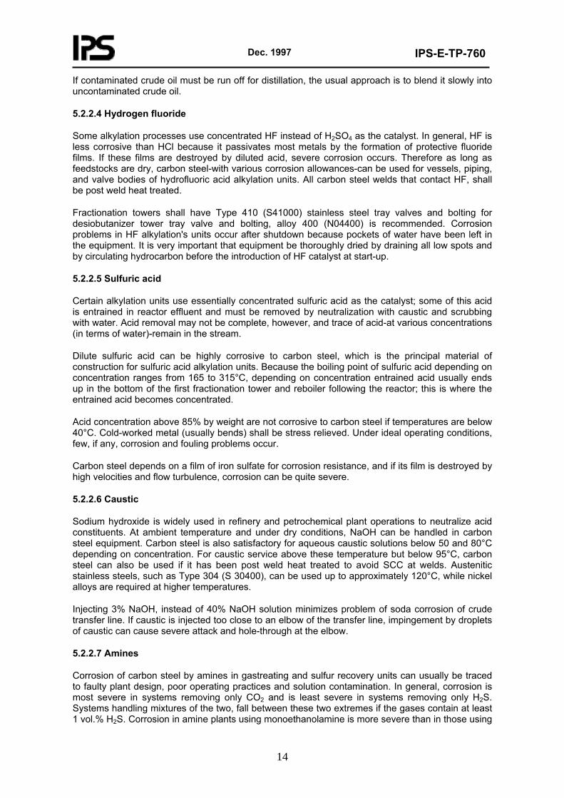
Crude distillation units that process mostly sour crude oils require additional alloy protection over the years, it has been found that corrosion rates predicated by the original McConomy curves shall be decreased by a factor of roughly 2.5, resulting in the modified curves shown in Fig. 5.1. The curves demonstrate the beneficial effects of alloying steel with chromium in order to reduce corrosion rates.
Temperature, °C
Temperature, °F
MODIFIED McCONOMY CURVES SHOWING THE EFFECT OF TEMPERATURE ON HIGH-TEMPERATURE ON HIGH-TEMPERATURE SULFIDIC CORROSION OF VARIOUS STEELS
AND STAINLESS STEEL Fig. 5.1
Metal skin temperature, rather than flow stream temperatures, shall be used to predict corrosion rates when significant differences between the two arise. For example metal temperatures of furnace tubes are typically 85 to 110°C higher than the temperature of the hydrocarbon stream passing through the tubes. Furnace tubes normally corrode at a higher rate on the hot side (fire side) than on the cool side (wall side).
5.3.3 Sulfidic corrosion with hydrogen present
The presence of hydrogen in, for example, hydrotreating and hydrocracking operations, increases the severity of hightemperature sulfidic corrosion. Hydrogen coverts organic sulfur compounds in feed stocks to hydrogen sulfide; corrosion becomes a function of H2S concentration.
Dec. 1997
IPS-E-TP-760
17
Down stream of hydrogen injection line, low-alloy steel piping usually requires aluminizing in order to minimize sulfidic corrosion. Alternatively Type 321 (S32100) stainless steel can be used. Tubes in the preheat furnace are aluminized low-alloy steel, aluminized 12% Cr stainless steel.
Reactors are usually made of 2.25 Cr-1 Mo steel, either with a Type 347 (S34700) stainless steel weld overlay or an internal factory lining. Reactor internals are often Type 321 stainless steel.
When selecting materials for this service, the recommendations of API 941-2004 shall be followed to avoid problems with high temperature hydrogen attack.
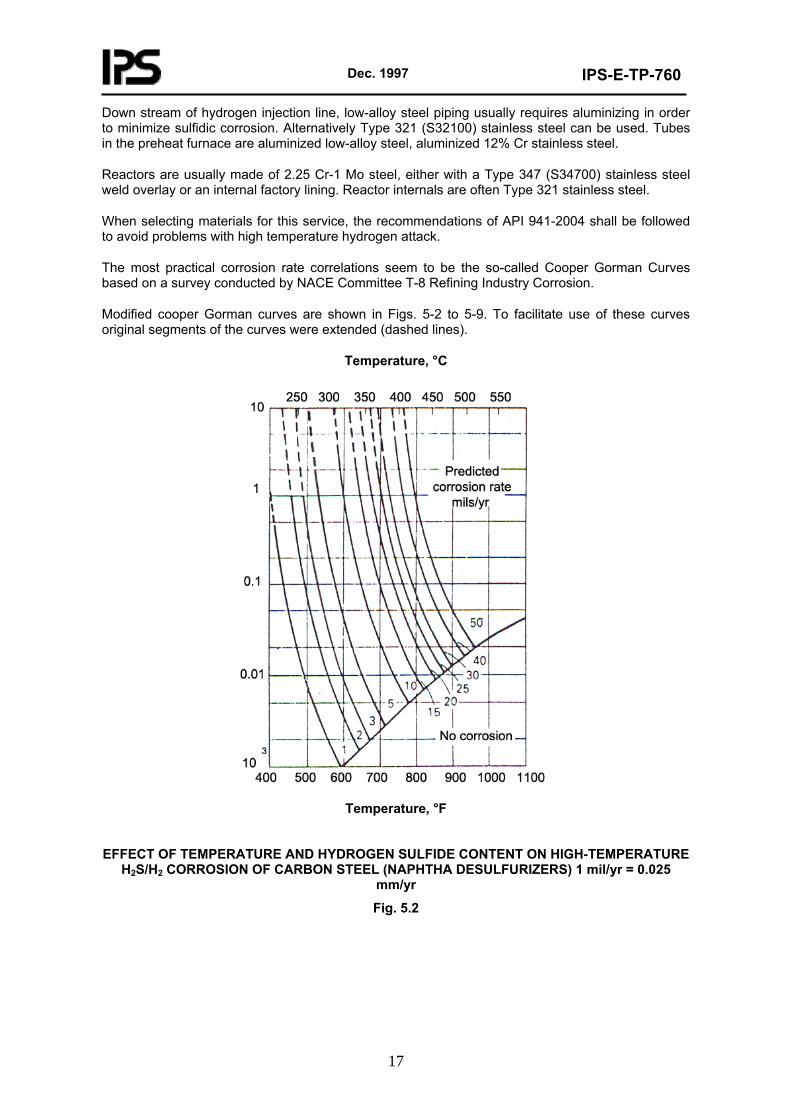
The most practical corrosion rate correlations seem to be the so-called Cooper Gorman Curves based on a survey conducted by NACE Committee T-8 Refining Industry Corrosion.
Modified cooper Gorman curves are shown in Figs. 5-2 to 5-9. To facilitate use of these curves original segments of the curves were extended (dashed lines).
Temperature, °C
Temperature, °F
EFFECT OF TEMPERATURE AND HYDROGEN SULFIDE CONTENT ON HIGH-TEMPERATURE
H2S/H2 CORROSION OF CARBON STEEL (NAPHTHA DESULFURIZERS) 1 mil/yr = 0.025 mm/yr
Fig. 5.2
Dec. 1997
IPS-E-TP-760
18
Temperature, °C
Temperature, °F
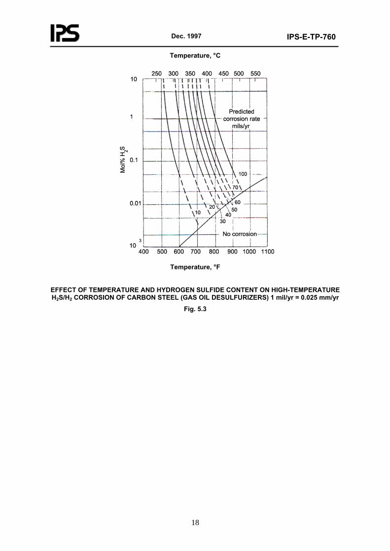
EFFECT OF TEMPERATURE AND HYDROGEN SULFIDE CONTENT ON HIGH-TEMPERATURE H2S/H2 CORROSION OF CARBON STEEL (GAS OIL DESULFURIZERS) 1 mil/yr = 0.025 mm/yr
Fig. 5.3
Dec. 1997
IPS-E-TP-760
19
Temperature, °C
Temperature, °F
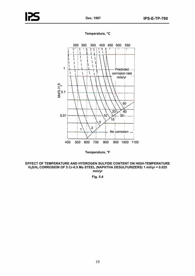
EFFECT OF TEMPERATURE AND HYDROGEN SULFIDE CONTENT ON HIGH-TEMPERATURE
H2S/H2 CORROSION OF 5 Cr-0.5 Mo STEEL (NAPHTHA DESULFURIZERS) 1 mil/yr = 0.025 mm/yr
Fig. 5.4
Dec. 1997
IPS-E-TP-760
20
Temperature, °C
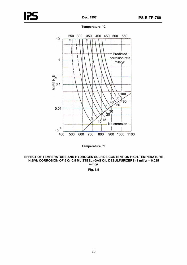
Temperature, °F
EFFECT OF TEMPERATURE AND HYDROGEN SULFIDE CONTENT ON HIGH-TEMPERATURE
H2S/H2 CORROSION OF 5 Cr-0.5 Mo STEEL (GAS OIL DESULFURIZERS) 1 mil/yr = 0.025 mm/yr
Fig. 5.5
Dec. 1997
IPS-E-TP-760
21
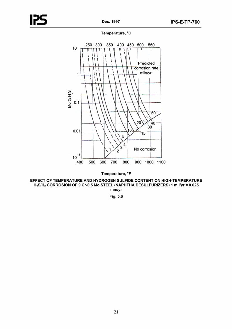
Temperature, °C
Temperature, °F
EFFECT OF TEMPERATURE AND HYDROGEN SULFIDE CONTENT ON HIGH-TEMPERATURE H2S/H2 CORROSION OF 9 Cr-0.5 Mo STEEL (NAPHTHA DESULFURIZERS) 1 mil/yr = 0.025
mm/yr
Fig. 5.6
Dec. 1997
IPS-E-TP-760
22
Temperature, °C
Temperature, °F
EFFECT OF TEMPERATURE AND HYDROGEN SULFIDE CONTENT ON HIGH-TEMPERATURE H2S/H2 CORROSION OF 9 Cr-0.5 Mo STEEL (GAS OIL DESULFURIZERS) 1 mil/yr = 0.025
mm/yr
Fig. 5.7
Dec. 1997
IPS-E-TP-760
23
Temperature, °C
Temperature, °F
EFFECT OF TEMPERATURE AND HYDROGEN SULFIDE CONTENT ON HIGH-TEMPERATURE H2S/H2 CORROSION OF 12% Cr STAINLESS STEEL 1 mil/yr = 0.025 mm/yr
Fig. 5.8
Dec. 1997
IPS-E-TP-760
24
Temperature, °C
Temperature, °F
EFFECT OF TEMPERATURE AND HYDROGEN SULFIDE CONTENT ON HIGH-TEMPERATURE H2S/H2 CORROSION OF 18 Cr-8Ni AUSTENITIC STAINLESS STEEL 1 mil/yr = 0.025 mm/yr
Fig. 5.9
Stainless steels containing at least 18% Cr are often required for complete immunity to corrosion because Couper- Gorman curves are primarily based on corrosion rate data for an all-vapor system, partial condensation can be expected to increase corrosion rates because of droplet impingement.
5.3.4 Naphthenic acids
These organic acids are present in many crude oils. The general formula may be written as R(CH2)n COOH, where R is usually cyclopentane ring. The higher molecular weight acids can be bicyclic (12 < n > 20), tricyclic (n > 20) and even polycyclic. Naphthenic acid content is generally expressed in terms of the neutralization number (total-acid number) which shall be evaluated by ASTM D 664 as mg KOH/grams of sample. This acid is corrosive only at temperature above 230°C in the range of 1 to 6 neutralization number encountered with crude oil and various side-cuts. At any given temperature, corrosion rate is proportional to neutralization number. Corrosion rate triples with each 55°C increase in temperature. In contrast to high-temperature sulfidic corrosion, no protective scale is formed, and low-alloy and stainless steels containing up to 12% Cr provide no benefits whatsoever over carbon steel. The presence of naphthenic acids may accelerate high-temperature sulfidic corrosion that occurs at furnace headers, elbows, ant tees of crude distillation units because of unfavorable flow conditions.
Dec. 1997
IPS-E-TP-760
25
Severe naphthenic acid corrosion (in the form of pitting) has been experienced in the vacuum towers of crude distillation units in the temperature zone of 290 to 345°C and sometimes as low as 230°C. Attack is often limited to the inside and very top of the outside surfaces of bubble caps as shown in Fig. 5.10.
NAPHTHENIC ACID CORROSION ON TOP OF 150 mm (6 in.) BUBBLE CAPS MADE FROM
TYPE 317 (S 31700) STAINLESS STEEL CONTAINING 2.95% Mo. TRAY TEMPERATURE WAS 305°C (580°F)
Fig. 5.10
Attacks on bubble caps are due to impinging droplets of condensing acids. Naphthenic acid corrosion is most easily controlled by blending crude oils having high neutralization numbers with other crude oils, in order to keep this neutralization number between 0.5 and 1.0. However, this does not prevent corrosion of vacuum tower internals operating in the 290 to 345°C range.
These should be made from Type 316 (S31600) or, preferably, Type 317 (S31700) stainless steel containing at least 3.5% Mo. The vacuum tower lining in this temperature range should also be Type 317 (S31700) stainless steel. Aluminum has excellent resistance to naphthenic acid corrosion in vacuum towers and can be used if its strength limitations and low resistance to velocity effects are kept in mind. Alloy 20 (N08020) and titanium Grade 2 (R50400) are also resistant to naphthenic acid corrosion. In contrast, aluminized carbon steel tray components, such as bubble caps, have performed poorly.
5.3.5 Fuel ash
Corrosion by fuel ash deposits can be one of the most serious operating problems with boiler and preheat furnaces. All fuels except natural gas contain certain inorganic contaminants that leave the furnace with products of combustion. These will deposit on heat-receiving surfaces, such as superheater tubes, and after melting can cause severe liquid-phase corrosion. Contaminant of this type include various combinations of vanadium, sulfur, and sodium compounds. Fuel ash corrosion is most likely to occur when residual fuel oil (Bunker C fuel) is burned.
In particular, vanadium pentoxide vapor (V2O5) reacts with sodium sulfate (Na2SO4) to form sodium
Dec. 1997
IPS-E-TP-760
26
vanadate (Na2O-6 V2O5). The latter compound reacts with steel, forming a molten slag that runs off and exposes fresh metal to attack.
Corrosion increases sharply with increasing temperature and vanadium content of fuel. If the vanadium content in the fuel oil exceeds 150 ppm, the maximum tube wall temperature should be limited to 650°C. Between 20 and 150 ppm V, maximum tube wall temperatures can be between 650 and 845°C depending on sulfur content and the sodium-vanadium ratio of the fuel oil. With 5 to 20 ppm V, the maximum tube wall temperature can exceed 845°C.
In general, most alloys are likely suffer from fuel ash corrosion. However, alloys with high chromium and nickel contents provide the best resistance to this type of attack. Sodium vanadate corrosion can be reduced by firing boilers with low excess air (<1%). This minimizes formation of sulfur trioxide in the firebox and produces high-melting slages containing vanadium tetroxide and trioxide rather than pentoxide. In the temperature range of 400 to 480°C boiler tubes are corroded by alkali pyrosulfates such as sodium pyrosulfate and potassium pyrosulfate, when appreciable concentrations of sulfur trioxide are present.
Additives can be helpful in controlling corrosion, particularly in conjunction with firing with low excess air. The effectiveness of the additives varies. The most useful additives are based on organic magnesium compounds. Additives raise the melting point of fuel ash deposits and prevent the formation of sticky and highly corrosive films. Instead, a porous and fluffy deposit layer is formed with additives that can be readily re-moved by periodic cleaning. Magnesium-type additives offer additional benefits with regard to cold-end corrosion in boilers. Sulfuric acid condenses at temperatures between 150 and 175°C (300 and 350°F), depending on sulfur content of the fuel oil, and can cause serious corrosion problems. Additives neutralize any free acid by forming magnesium sulfate.
5.3.6 Oxidation
Carbon steels, low-alloy steels and stainless steels react at elevated temperatures with oxygen in the surrounding air and become scaled. Nickel alloys can also become oxidized, especially if spalling of scale occur. The oxydation of copper alloys usually is not a problem, because these are rarely used where operating temperatures exceed 260°C. Alloying with both chromium and nickel increases scaling resistance. Stainless steels or nickel alloys except alloy 400 (N04400), are required to provide satisfactory oxidation resistance at temperatures above 705°C.
Thermal cycling, applied stresses, moisture and sulfur-bearing gases will decrease scaling resistance.
High temperature oxidation is limited to the outside surfaces of furnace tubes, tube hangers and other parts that are exposed to combustion gases containing excess air.
At elevated temperatures, steam decomposes at metal surfaces to hydrogen and oxygen and may cause steam oxidation which is more severe than air oxidation at the same temperature. Fluctuating steam temperatures tend to increase the rate of oxidation by causing scale to spall and thus expose fresh metal to further attack.
5.4 SCC and Embrittlement
Stress-Corrosion Cracking and environmental embrittlement are the most insidious forms of failure that can be experienced by process equipment, because they tend to strike without warning. There is no noticeable yielding or bulging of the component, there is no measurable metal loss, and through-thickness cracks can form in as little as 1 to 2 h after initial exposure to a crack-inducing environment. For example, cracking throughout an entire furnace coil occurred within 1 h after exposure to air and the resultant formation of polythionic acids.
Towers and heat exchangers had to be scrapped because of hydrogen blistering, embrittlement, and stress cracking at welds. High temperature hydrogen attack has resulted in the sudden rupture of pressure vessels.
Dec. 1997
IPS-E-TP-760
27
Environments affected stress-corrosion cracking, are summarized as follows:
- Chlorides;
- Caustics;
- Ammonia;
- Amines;
- Polythionic acids.
5.4.1 Chloride cracking
Chlorides are the most common cause of SCC of austenitic stainless steels and nickel alloys. In theory, one would need a single chloride ion in water with sufficient oxygen and residual stresses present, to cause cracking. In practice however, the permissible limits on chloride ion content are higher.
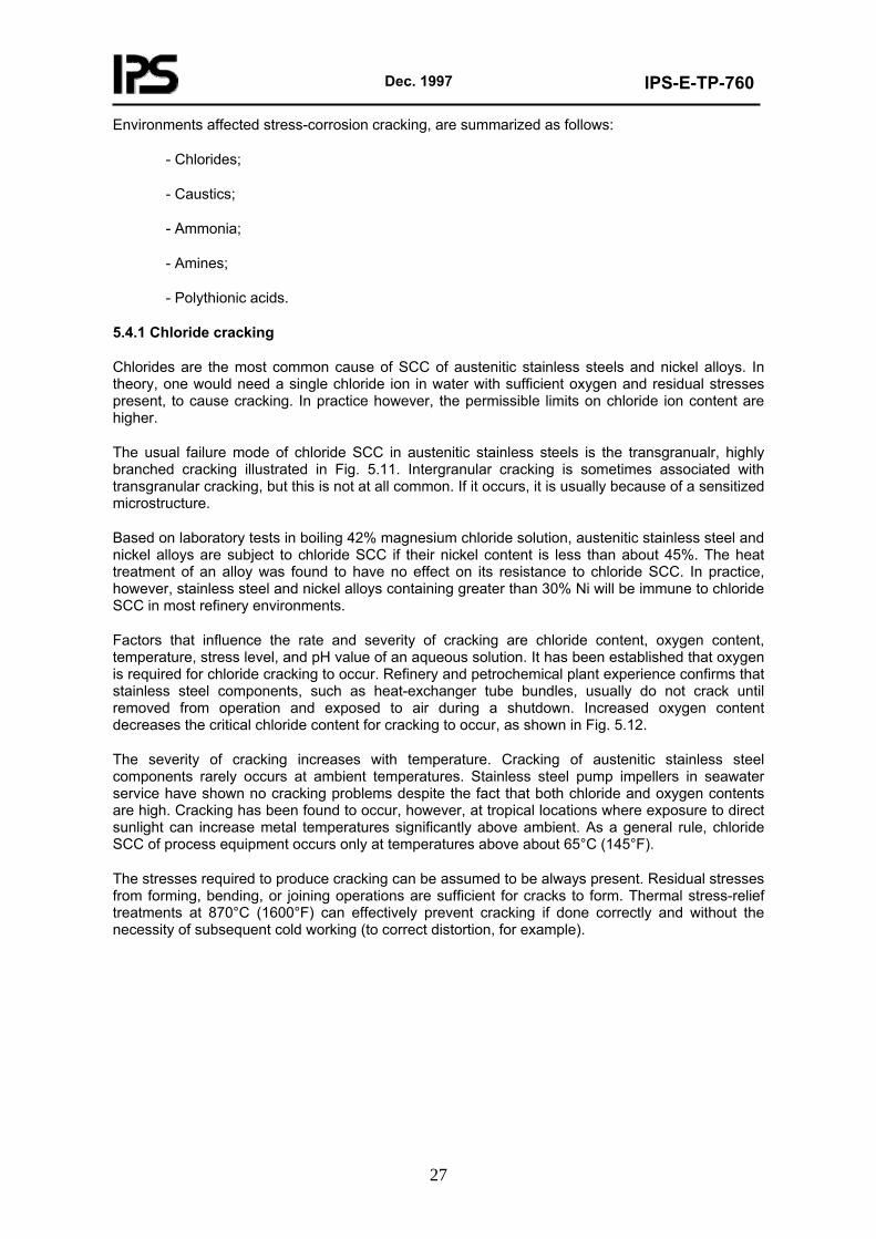
The usual failure mode of chloride SCC in austenitic stainless steels is the transgranualr, highly branched cracking illustrated in Fig. 5.11. Intergranular cracking is sometimes associated with transgranular cracking, but this is not at all common. If it occurs, it is usually because of a sensitized microstructure.
Based on laboratory tests in boiling 42% magnesium chloride solution, austenitic stainless steel and nickel alloys are subject to chloride SCC if their nickel content is less than about 45%. The heat treatment of an alloy was found to have no effect on its resistance to chloride SCC. In practice, however, stainless steel and nickel alloys containing greater than 30% Ni will be immune to chloride SCC in most refinery environments.
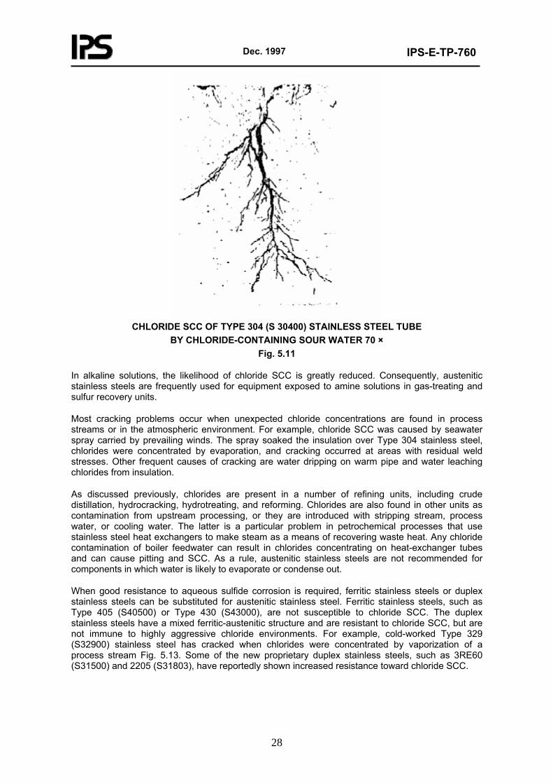
Factors that influence the rate and severity of cracking are chloride content, oxygen content, temperature, stress level, and pH value of an aqueous solution. It has been established that oxygen is required for chloride cracking to occur. Refinery and petrochemical plant experience confirms that stainless steel components, such as heat-exchanger tube bundles, usually do not crack until removed from operation and exposed to air during a shutdown. Increased oxygen content decreases the critical chloride content for cracking to occur, as shown in Fig. 5.12.
The severity of cracking increases with temperature. Cracking of austenitic stainless steel components rarely occurs at ambient temperatures. Stainless steel pump impellers in seawater service have shown no cracking problems despite the fact that both chloride and oxygen contents are high. Cracking has been found to occur, however, at tropical locations where exposure to direct sunlight can increase metal temperatures significantly above ambient. As a general rule, chloride SCC of process equipment occurs only at temperatures above about 65°C (145°F).
The stresses required to produce cracking can be assumed to be always present. Residual stresses from forming, bending, or joining operations are sufficient for cracks to form. Thermal stress-relief treatments at 870°C (1600°F) can effectively prevent cracking if done correctly and without the necessity of subsequent cold working (to correct distortion, for example).
Dec. 1997
IPS-E-TP-760
28
CHLORIDE SCC OF TYPE 304 (S 30400) STAINLESS STEEL TUBE
BY CHLORIDE-CONTAINING SOUR WATER 70 × Fig. 5.11
In alkaline solutions, the likelihood of chloride SCC is greatly reduced. Consequently, austenitic stainless steels are frequently used for equipment exposed to amine solutions in gas-treating and sulfur recovery units.
Most cracking problems occur when unexpected chloride concentrations are found in process streams or in the atmospheric environment. For example, chloride SCC was caused by seawater spray carried by prevailing winds. The spray soaked the insulation over Type 304 stainless steel, chlorides were concentrated by evaporation, and cracking occurred at areas with residual weld stresses. Other frequent causes of cracking are water dripping on warm pipe and water leaching chlorides from insulation.
As discussed previously, chlorides are present in a number of refining units, including crude distillation, hydrocracking, hydrotreating, and reforming. Chlorides are also found in other units as contamination from upstream processing, or they are introduced with stripping stream, process water, or cooling water. The latter is a particular problem in petrochemical processes that use stainless steel heat exchangers to make steam as a means of recovering waste heat. Any chloride contamination of boiler feedwater can result in chlorides concentrating on heat-exchanger tubes and can cause pitting and SCC. As a rule, austenitic stainless steels are not recommended for components in which water is likely to evaporate or condense out.
When good resistance to aqueous sulfide corrosion is required, ferritic stainless steels or duplex stainless steels can be substituted for austenitic stainless steel. Ferritic stainless steels, such as Type 405 (S40500) or Type 430 (S43000), are not susceptible to chloride SCC. The duplex stainless steels have a mixed ferritic-austenitic structure and are resistant to chloride SCC, but are not immune to highly aggressive chloride environments. For example, cold-worked Type 329 (S32900) stainless steel has cracked when chlorides were concentrated by vaporization of a process stream Fig. 5.13. Some of the new proprietary duplex stainless steels, such as 3RE60 (S31500) and 2205 (S31803), have reportedly shown increased resistance toward chloride SCC.
Dec. 1997
IPS-E-TP-760
29
SYNERGISTIC EFFECT OF CHLORIDES AND OXYGEN ON THE SCC OF TYPE 304 (S30400) STAINLESS STEEL. THE TESTS WERE CONDUCTED AT 250 TO 300°C (480 TO 570°F) AT A
STRAIN RATE OF < 10-5. 5-1. Fig. 5.12
There are no simple methods of preventing SCC when an austenitic stainless steel must be used in an environment known to contain chlorides. Chloride SCC in refineries and petrochemical plants often occurs under shutdown conditions when air and moisture enters equipment opened for inspection and repair. It has been found that the precautionary measures outlined in NACE RP-01-70 for the prevention of cracking by polythionic acids also help prevent cracking by chlorides. In particular, excluding air and moisture by nitrogen blanketing and rinsing equipment with an aqueous 0.5% sodium nitrate or sodium carbonate 3-5% solution have been shown to inhibit chloride SCC. To prevent chloride SCC on the outside of insulated pipe, aluminum foil has been wrapped between the insulation and pipe to provide some measure of cathodic protection. One method of preventing the catastrophic failure of components by chloride SCC would be the use of austenitic stainless steel as an internal cladding. The highly branched mode of any cracking would effectively prevent the development of stress raisers. Carbon or low alloy steel base metal would not be susceptible to cracking in chloride solutions, but some localized corrosion may occur. This type of construction would also provide resistance to cracking when chlorides are liable to contact the outside of the components, as in external insulation, for example.
Dec. 1997
IPS-E-TP-760
30
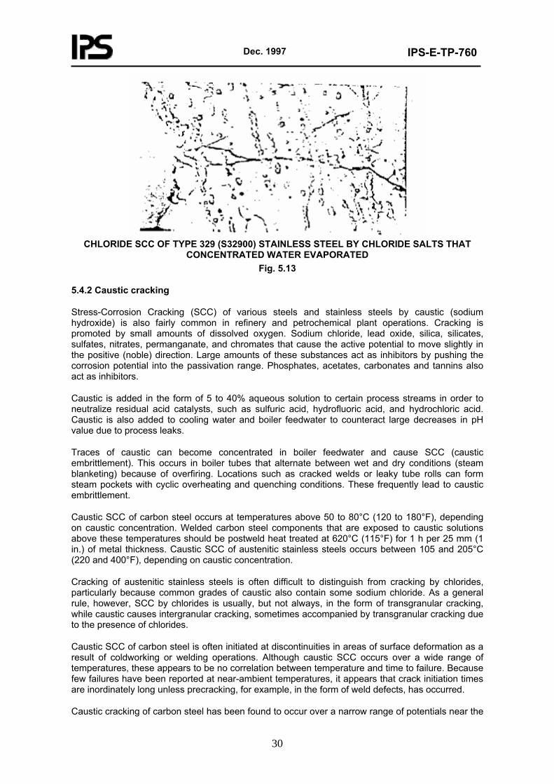
CHLORIDE SCC OF TYPE 329 (S32900) STAINLESS STEEL BY CHLORIDE SALTS THAT
CONCENTRATED WATER EVAPORATED Fig. 5.13
5.4.2 Caustic cracking
Stress-Corrosion Cracking (SCC) of various steels and stainless steels by caustic (sodium hydroxide) is also fairly common in refinery and petrochemical plant operations. Cracking is promoted by small amounts of dissolved oxygen. Sodium chloride, lead oxide, silica, silicates, sulfates, nitrates, permanganate, and chromates that cause the active potential to move slightly in the positive (noble) direction. Large amounts of these substances act as inhibitors by pushing the corrosion potential into the passivation range. Phosphates, acetates, carbonates and tannins also act as inhibitors.
Caustic is added in the form of 5 to 40% aqueous solution to certain process streams in order to neutralize residual acid catalysts, such as sulfuric acid, hydrofluoric acid, and hydrochloric acid. Caustic is also added to cooling water and boiler feedwater to counteract large decreases in pH value due to process leaks.
Traces of caustic can become concentrated in boiler feedwater and cause SCC (caustic embrittlement). This occurs in boiler tubes that alternate between wet and dry conditions (steam blanketing) because of overfiring. Locations such as cracked welds or leaky tube rolls can form steam pockets with cyclic overheating and quenching conditions. These frequently lead to caustic embrittlement.
Caustic SCC of carbon steel occurs at temperatures above 50 to 80°C (120 to 180°F), depending on caustic concentration. Welded carbon steel components that are exposed to caustic solutions above these temperatures should be postweld heat treated at 620°C (115°F) for 1 h per 25 mm (1 in.) of metal thickness. Caustic SCC of austenitic stainless steels occurs between 105 and 205°C (220 and 400°F), depending on caustic concentration.
Cracking of austenitic stainless steels is often difficult to distinguish from cracking by chlorides, particularly because common grades of caustic also contain some sodium chloride. As a general rule, however, SCC by chlorides is usually, but not always, in the form of transgranular cracking, while caustic causes intergranular cracking, sometimes accompanied by transgranular cracking due to the presence of chlorides.
Caustic SCC of carbon steel is often initiated at discontinuities in areas of surface deformation as a result of coldworking or welding operations. Although caustic SCC occurs over a wide range of temperatures, these appears to be no correlation between temperature and time to failure. Because few failures have been reported at near-ambient temperatures, it appears that crack initiation times are inordinately long unless precracking, for example, in the form of weld defects, has occurred.
Caustic cracking of carbon steel has been found to occur over a narrow range of potentials near the
Dec. 1997
IPS-E-TP-760
31
active current peak of potential/log current curves. Typically, this potential range is centered about -700 mV versus the Standard Hydrogen Electrode (SHE). The most negative (active) potential for inducing caustic cracking coincides with the potential for initiating passivation by magnetite (Fe3O4) formation. Cracking is promoted by small amounts of dissolved oxygen, sodium
chloride, lead oxide, silica, silicates, sulfates, nitrates, permanganate, and chromates that cause the active corrosion potential to move slightly in the positive (noble) direction. In contrast, large amounts of these substances act as inhibitors by pushing the corrosion potential into the passivation range. Phosphates, acetates, carbonates, and tannins also act as inhibitors.
5.4.3 Ammonia cracking
Ammonia has caused two types of SCC in refineries and petrochemical plants. The first is cracking of carbon steel in anhydrous ammonia service, and the second type is cracking of copper alloys, such as admiralty metal (C 44300). In copper alloys, SCC can occur by ammonia-base neutralizers that are added to control corrosion.
Carbon steel storage vessels, primarily spheres, have developed stress-corrosion cracks in anhydrous ammonia service at ambient temperature but elevated pressure. In most cases, cracking was detected by inspection before leakage or rupture, but there were at least two catastrophic failures. There have been few problems with semirefrigerated storage vessels and no documented cases of SCC in cryogenic storage vessels. The primary causes of cracking are high stresses, hard welds, and air contamination.
To minimize the likelihood of cracking, only low strength steels, with a maximum tensile strength of 483 MPa (70 ksi), should be used in anhydrous ammonia service. Welds should be postweld heat treated 595°C (1100°F) or higher, with a maximum allowable hardness of 225 HB. A water content of at least 0.2% should be maintained in the ammonia because water has been found to be an effective inhibitor of cracking. Air contamination increases the tendency toward cracking and shall be minimized, if necessary, by the addition of hydrazine to the water. With a water content of 10 ppm, the oxygen content should be below 10 ppm for safe operation. The permissible oxygen content increases to 100 ppm with a water content of 0.1 percent. Regular inspection of all components in anhydrous ammonia service is recommended.
Cracking of admiralty metal (C 44300) heat-exchanger tubes has been recurring problem in number of refining units and petrochemical process units. For example, ammonia is often used to neutralize acidic constituents, such as hydrogen chloride or sulfur dioxide, in overhead systems crude of distillation or alkylation units, respectively. Stripped sour water containing residual ammonia is used as desalter water at some crude distillation units. This practice causes ammonia contamination of the overhead system even if no ammonia is added intentionally. Ammonia is formed from nitrogencontaining feed stocks during catalytic cracking, hydrotreating, and hydrocracking operations. As a rule, cracking of admiralty metal (C 44300) tubes occurs only during shutdowns when ammonia-containing deposits on the tube surface become exposed to air. To prevent cracking tube bundles should be sprayed with a very dilute solution of sulfuric acid immediately after they are pulled from their shells in order to neutralize an residual ammonia. Cracking of admiralty metal (C 44300) tubes has occasionally been attributed to traces of ammonia in cooling water.
5.4.4 Amine cracking
Stress-Corrosion Cracking (SCC) of carbon steel by aqueous amine solutions, which are used to remove hydrogen sulfide and carbon dioxide from refinery and petrochemical plant streams, has been a recurring problem for number of years.
Cracking was found primarily at temperatures ranging from 50°C up to 95°C. Cracking was intergranular, with crack surface covered by a thin film of magnetite. No crack was found in piping that had received postweld heat treatment.
To prevent amine SCC, postweld heat treatment at 620°C as recommended for carbon steel welds exposed to amine solutions at temperatures exceeding 95°C shall be done.
Dec. 1997
IPS-E-TP-760
32
5.4.5 Polythionic acid cracking
Polythionic acid SCC occurs only in austenitic stainless steels and nickel-chromium-iron alloys that have become sensitized through thermal exposure. Sensitization occurs when the carbon present in the alloy reacts with chromium to produce chromium carbides at the grain boundaries. As a result, the areas adjacent to the grain boundaries become depleted in chromium and are no longer fully resistant to certain corrosive environments.
Sensitization of Type 304 (S30400) stainless steels normally occurs at temperatures between 370 and 815°C (750 and 1500°F), whenever the alloy is slowly cooled through this temperature range (such as during welding and heat treating), or during normal process operations. The higher the temperature, the shorter the time of exposure required for sensitization. Addition of stabilizing elements, such as titanium or niobium, or limiting the amount of carbon are two methods for reducing the effects of welding and heat treating on sensitization. However, they are not effective for long-term exposure to temperatures above 430°C (800°F). The resistance of titanium-stabilized Type 321 (S32100) stainless steel to polythionic SCC can be significantly improved by a thermal stabilization at approximately 900°C (1650°F) and holding for 2 h, with no specific limits on the cooling rate.
Laboratory studies and plant experiences have demonstrated that austenitic stainless steels are not sensitized when applied as a weld overlay over carbon or low-alloy steels. SCC of the roll-bonded cladding stops at the weld overlay around the nozzle.
Polythionic acids of the Type H2SxOy (including sulfurous acid) are formed by the reaction of oxygen and water with the iron/chromium sulfide scale that covers the surfaces of austenitic stainless steel components as a result of high temperature sulfidic corrosion. Because neither oxygen nor water is present during normal operation under conditions in which austenitic stainless steels would be used, SCC evidently occurs during shutdowns. Oxygen and water originate from steam or wash water used to free components of hydrocarbons during shutdown before inspection or simply from atmospheric exposure. In catalytic cracking units, oxygen and water can be present during normal operations at certain locations of the catalyst regeneration system because of steam purges and water sprays for preventing catalyst accumulation. The components involved include air rings, plenums, slide valves, cyclone components, and expansion joint bellows in the catalyst regenerator and associated lines.
In general, however, SCC by polythionic acids is considered to be a problem primarily during shutdown periods; suitable procedures to prevent cracking are outlined in NACE RP-01-70. These procedures include nitrogen purging of components that were opened to the atmosphere, purging with dry air having a dew point below -15°C (5°F), or neutralizing any polythionic acids that are formed, by washing components with a 2% aqueous soda ash (sodium carbonate) solution.
Soda ash solution should also be used for hydro testing prior to returning components to service.
5.5 Hydrogen Damage
Corrosion of carbon and low-alloy steels by aqueous hydrogen sulfide solutions or sour waters can result in one or more types of hydrogen damage. These include loss of ductility on slow application of strain (hydrogen embrittlement), formation of blisters or internal voids (hydrogen blistering), and spontaneous cracking of high-strength or high-hardness steels (hydrogen stress cracking).
Hydrogen stress cracking of embrittled metal is caused by static external stresses, transformation stresses (for example, as a result of welding), internal stresses, cold working, and hardening. As a rule, cracking does not occur in ductile steels or in steels that have received a proper postweld heat treatment.
Hydrogen damage occurs primarily when steel is exposed to aqueous hydrogen sulfide solutions having low pH values. Aqueous hydrogen sulfide solutions having high pH values can also cause hydrogen damage if cyanides are present. In the absence of cyanides, aqueous hydrogen sulfide solutions with pH values above 8 do not corrode steel, because a protective iron sulfide film forms
Dec. 1997
IPS-E-TP-760
33
on the surface.
Cyanides destroy this protective film and convert it into soluble Ferro cyanide [Fe(CN)6 -4]
complexes. As a result, the now unprotected steel can corrode very rapidly. For practical purposes, the corrosion rate depends primarily on the disulfide ion (SH - ) concentration and, to a lesser extent, on the cyanide ion (CN-) concentration. The more disulfide ion that is present, the more cyanide that is required to destroy the protective iron sulfide film. It has been shown experimentally that corrosion of steel in aqueous ammonia/sulfide/cyanide solutions with pH values above 8 is always accompanied by hydrogen damage. Hydrogen damages have different types as follows:
- Hydrogen embrittlement;
- Hydrogen blistering;
- Hydrogen stress cracking.
5.5.1 Hydrogen embrittlement
Hydrogen embrittlement is characterized by decreasing ductility with decreasing strain rate; this is contrary to metal behavior in most other types of embrittlement. For example, the ductility of carbon steel has been reported to drop from 42 to 7% when charged with hydrogen. This loss of ductility is only observed during slow strain rate testing and conventional tensile tests, but not during impact tests, such as the Charpy V-notch test. Failure, in the form of cracking, usually occurs some time after a load is applied to hydrogen-charged steel. Because this phenomenon is also known as static fatigue, the minimum load for failure to occur is known as the static fatigue limit.
Hydrogen embrittlement is temporary and can be reversed by heating the steel to drive out the hydrogen. The rate of recovery depends on time and temperature. Heating to 230°C (450°F) and holding for 1 h/25 mm (1 in.) of thickness has been found to be adequate to prevent cracking after welding. Although temperatures as high as 650°C (1200°F) for 2 h or as low as 105°C (225°F) for 1 day have reportedly been used to restore full ductility, even the heat of the sun on a summer day was found to be sufficient to restore ductility to a high-carbon cold-drawn steel wire that had been embrit- tled by exposure to wet hydrogen sulfide. As a rule, however, heating to temperatures above 315°C (600°F) for any length of time should be avoided to lessen the possibility of high-temperature hydrogen attack.
Titanium can also become embrittled by absorbed hydrogen as a result of corrosion or exposure to dry hydrogen gas. When hydrogen is absorbed by titanium in excess of about 150 ppm, a brittle titanium hydride phase will precipitate out. Embrittlement due to titanium hydride precipitation is usually permanent and can be reversed only by vacuum annealing, which is difficult to perform. Absorption of hydrogen by titanium dramatically increases once the protective oxide film normally present on the metal is damaged through either mechanical abrasion or chemical reduction. Hydrogen intake is accelerated by the presence of surface contaminants, including iron smears, and occurs predominantly as temperatures exceed 70°C (160°F).
Hydrating can be minimized by anodizing or thermal oxidizing treatments to increase the thickness of the protective oxide film. If it is impractical to apply these treatments, acid pickling of titanium components-with 10 to 30 vol.% nitric acid containing 1 to 3 vol.% hydrofluoric acid at 49 to 52°C (120 to 125°F) for 1 to 5 min-can be performed to remove iron smears. Acid pickling is also recommended for cleaning titanium components after inspection and repairs during shutdowns, especially components exposed to concentrated acetic acid in certain petrochemical operations. To minimize hydrogen pickup during pickling, the volume ratio of nitric acid to hydrofluoric acid should be near 10. In some highly aggressive process environments, titanium components may have to be electrically insulated from more anodic components, such as aluminum, to prevent hydride formation as a result of hydrogen evolution on titanium surfaces. When process streams contain a significant volume of hydrogen (for example, reactor effluent from hydrotreating units), titanium should be used only at temperatures below 175°C (350°F).
Dec. 1997
IPS-E-TP-760
34
5.5.2 Hydrogen blistering
Hydrogen blistering has been a problem primarily in the vapor recovery (light ends) section of catalytic cracking units and, to a lesser degree, in the low-temperature areas of the reactor effluent section of hydrotreating and hydrocracking units. Hydrogen blistering has also been seen in the overhead systems for sour water stripper towers and amineregenerator (stripper) towers, as well as in the bottom of amine contactor (absorber) towers.
Hydrogen blistering often accompanies hydrogen embrittlement as a result of aqueous sulfide corrosion. As a rule, the severity of hydrogen blistering depends on the severity of corrosion, but even low corrosion rates can produce enough hydrogen to cause extensive damage. In some cases hydrogen blistering is limited to dirty steel with highly oriented slag inclusions or laminations. Vapor/liquid interface areas in equipment often show most of the damage.
The basic approach toward reducing corrosion and hydrogen blistering in the various vapor-compression stages of catalytic cracking units should be aimed at decreasing the concentration of cyanide and disulfide ions in water condensate. Several methods for accomplishing this have been tried over the years. Conversion of cyanide to harmless thiocyanate (SCN - ) by injection of air or polysulfide solutions at various locations has often produced undesirable side effects, such as accelerated corrosion and fouling at stagnant-flow areas. In contrast, water washing of the compressed wet-gas streams, in conjunction with corrosion inhibitor injection, has been found to be very effective when applied correctly and consistently. Water washing reduces the concentration of cyanides by improved contacting of vapors and dilution of water condensate. To prevent dissolved and suspended solids from fouling the compressor aftercooler, only water of fairly good quality, such as boiler feed water or steam condensate, should be injected. To reduce the amount of freshwater used, stripping-stream condensate from the reflux drum can be used. As a rule, there is sufficient stripping-steam condensate to meet the wash-water requirements.
It is important that the waste sour water from the interstage and high-pressure separator drums be sent directly to waste disposal rather than first being recycled to the reflux drum. Waste water is often recycled for convenience so that its pressure can be reduced in the reflux drum prior to disposal. This alleviates the need for an external depressuring drum, but will build up the concentration of ammonia, hydrogen sulfide, and, especially, hydrogen cyanide in the wet gas leaving the reflux drum. Consequently, excessive concentrations of cyanides will be found in water condensing in the highpressure stage. Water washing of the overhead of the debutanizer and depropanizer is indicated only if serious fouling problems occur. Normally, these streams are quite dry and should be kept that way to minimize corrosion and hydrogen blistering problems. With proper water washing of the compressed wet-gas stream, water washing of the overhead vapor streams of the debutanizer and depropanizer towers becomes unnecessary.
Corrosion inhibitors help control aqueous sulfide corrosion and hydrogen blistering even though cyanides may still be present. Hydrogen activity probes and chemical tests of water condensate are used to monitor the effectiveness of water washing and inhibitor injection. Where limited hydrogen blistering occurs in certain components of hydrotreating and hydrocracking units, it is usually sufficient to line affected areas with stainless steel or alloy 400 (N04400). This also applies to components of overhead systems for sour water stripper towers and amine regenerator (stripper) towers or the bottoms of amine contactor (absorber) towers.
5.5.3 Hydrogen stress cracking
Sour water containing hydrogen sulfide can cause spontaneous cracking of highly stressed high-strength steel components, such as bolting and compressor rotors. Cracking has also occurred in carbon steel components containing hard welds. Hydrogen stress cracking was first identified in the production of sour crude oils when high-strength steels used for wellhead and down-hole equipment cracked readily after contacting produced water that contained hydrogen sulfide. Hydrogen stress cracking was not experienced by refineries gas industries and petrochemical plants until the introduction of high pressure processes that required high-strength bolting and other components gas compressors. With the increased use of submerged arc welding for pressure vessel construction it was found that weld deposits significantly harder and stronger than the base metal
Dec. 1997
IPS-E-TP-760
35
could be produced. This led to transverse cracking in the weld deposit.
In general terms, hydrogen stress cracking occurs in the same corrosive environments that lead to hydrogen embrittlement. Hydrogen sulfide affects the corrosion rate and the relative amount of hydrogen absorption, but otherwise does not appear to be directly involved in the cracking mechanism. As a general rule of thumb, hydrogen stress cracking can be expected to occur in process streams containing in excess of 50 ppm hydrogen sulfide (although cracking has been found to occur at lower concentrations).
There is a direct relationship between hydrogen sulfide concentration and the allowable maximum hardness value of the HAZ on one hand and cracking threshold stress on the other. Typically, the allowable maximum hardness value decreases 30 HB, and the allowable threshold stress decreases by 50% for a tenfold increase in hydrogen sulfide concentration. Also, hydrogen stress cracking occurs primarily at ambient temperature. As in the case of hydrogen embrittlement and hydrogen blistering, hydrogen stress cracking of steel in refineries and petrochemical plants often requires the presence of cyanides.
The most effective way of preventing hydrogen stress cracking is to ensure that the steel is in the proper metallurgical condition. This means that weld hardness is limited to 200 HB. Because hard zones can also form in the HAZs of welds and shell plates from hot forming, the same hardness limitation shall be applied in these areas. Guidelines for dealing with the hydrogen stress cracking that occurs in refineries and petrochemical plants are given in NACE RP 0472-2000.
Post weld heat treatment of fabricated equipment will greatly reduce the occurrence of hydrogen stress cracking. The effect is twofold: First, there is the tempering effect of heating to 620°C (115°F) on any hard microstructure, and second, the residual stresses from welding or forming are reduced. The residual stresses represent a much larger strain on the equipment that internal pressure stresses.
A large number of the ferrous alloys, including the stainless steels, as well as certain nonferrous alloys, are susceptible to hydrogen stress cracking. Cracking may be expected to occur with carbon and low-alloy steels when the tensile strength exceeds 620 MPa (90 ksi). Because there is a relationship between hardness and strength in steels, the above strength level approximates the 200 HB hardness limit. For other ferrous and nonferrous alloys used primarily in oil field equipment, limits on hardness and/or heat treatment have been established in NACE MR 0175/ISO 15156-2003. Although oil field environments can be more severe than those encountered during refining, the recommendations can be used as a general guide for material selection (see also IPS-E-TP-740).
5.6 Hydrogen Attack
5.6.1 The term hydrogen attack (or, more specifically, high-temperature hydrogen attack) refers to the deterioration of the mechanical properties of steels in the presence of hydrogen gas at elevated temperatures and pressures. Although not a corrosion phenomenon in the usual sense, hydrogen attack is potentially a very serious problem with regard to the design and operation of refinery equipment in hydrogen service. It is of particular concern in hydrotreating, reforming, and hydrocracking units at above roughly 260°C (500°F) and hydrogen partial pressures above 689 kPa (100 psia). Hydrogen attack takes the form of overall decarburization rather than blistering or cracking.
The overall effect of hydrogen attack is the partial depletion of carbon in pearlite (decarburization) and the formation of fissures in the metal. Hydrogen attack is accompanied by loss of tensile strength and ductility. Consequently, unexpected failure of equipment without prior warning signs is the primary cause for concern.
5.6.2 Forms of hydrogen attack
Hydrogen attack can take several forms within the metal structure, depending on the severity of the attack, stress, and the presence of inclusions in the steel. The following discussion will illustrate
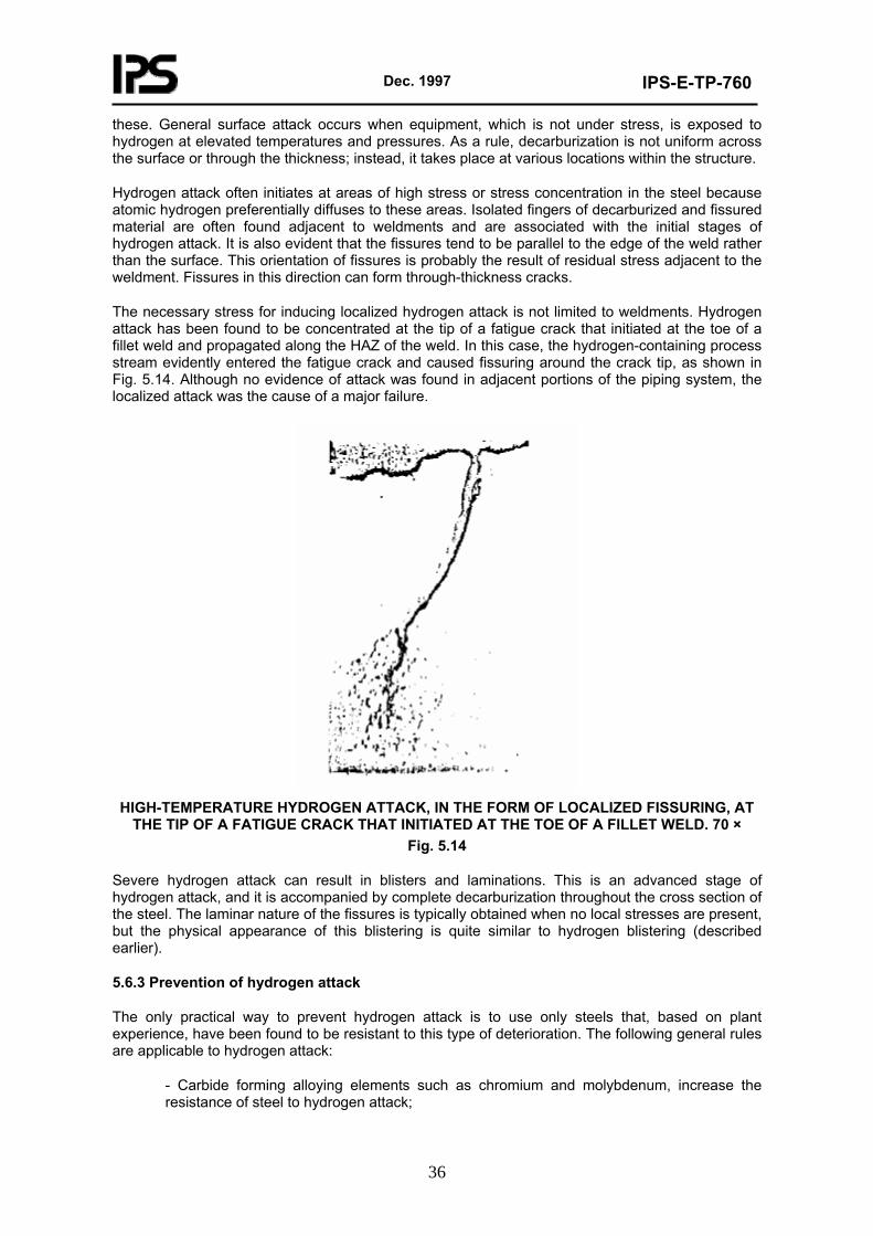
Dec. 1997
IPS-E-TP-760
36
these. General surface attack occurs when equipment, which is not under stress, is exposed to hydrogen at elevated temperatures and pressures. As a rule, decarburization is not uniform across the surface or through the thickness; instead, it takes place at various locations within the structure.
Hydrogen attack often initiates at areas of high stress or stress concentration in the steel because atomic hydrogen preferentially diffuses to these areas. Isolated fingers of decarburized and fissured material are often found adjacent to weldments and are associated with the initial stages of hydrogen attack. It is also evident that the fissures tend to be parallel to the edge of the weld rather than the surface. This orientation of fissures is probably the result of residual stress adjacent to the weldment. Fissures in this direction can form through-thickness cracks.
The necessary stress for inducing localized hydrogen attack is not limited to weldments. Hydrogen attack has been found to be concentrated at the tip of a fatigue crack that initiated at the toe of a fillet weld and propagated along the HAZ of the weld. In this case, the hydrogen-containing process stream evidently entered the fatigue crack and caused fissuring around the crack tip, as shown in Fig. 5.14. Although no evidence of attack was found in adjacent portions of the piping system, the localized attack was the cause of a major failure.
HIGH-TEMPERATURE HYDROGEN ATTACK, IN THE FORM OF LOCALIZED FISSURING, AT
THE TIP OF A FATIGUE CRACK THAT INITIATED AT THE TOE OF A FILLET WELD. 70 × Fig. 5.14
Severe hydrogen attack can result in blisters and laminations. This is an advanced stage of hydrogen attack, and it is accompanied by complete decarburization throughout the cross section of the steel. The laminar nature of the fissures is typically obtained when no local stresses are present, but the physical appearance of this blistering is quite similar to hydrogen blistering (described earlier).
5.6.3 Prevention of hydrogen attack
The only practical way to prevent hydrogen attack is to use only steels that, based on plant experience, have been found to be resistant to this type of deterioration. The following general rules are applicable to hydrogen attack:
- Carbide forming alloying elements such as chromium and molybdenum, increase the resistance of steel to hydrogen attack;
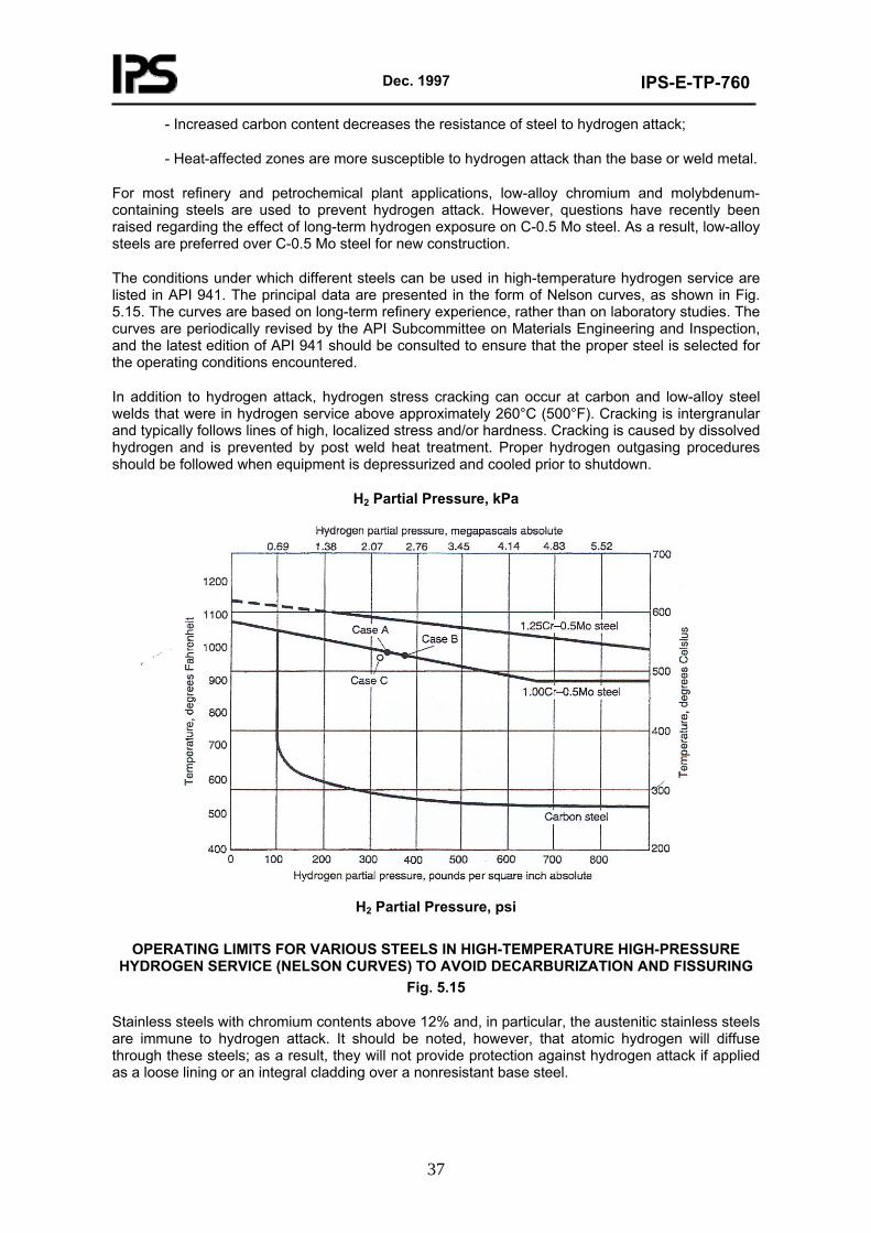
Dec. 1997
IPS-E-TP-760
37
- Increased carbon content decreases the resistance of steel to hydrogen attack;
- Heat-affected zones are more susceptible to hydrogen attack than the base or weld metal.
For most refinery and petrochemical plant applications, low-alloy chromium and molybdenum-containing steels are used to prevent hydrogen attack. However, questions have recently been raised regarding the effect of long-term hydrogen exposure on C-0.5 Mo steel. As a result, low-alloy steels are preferred over C-0.5 Mo steel for new construction.
The conditions under which different steels can be used in high-temperature hydrogen service are listed in API 941. The principal data are presented in the form of Nelson curves, as shown in Fig. 5.15. The curves are based on long-term refinery experience, rather than on laboratory studies. The curves are periodically revised by the API Subcommittee on Materials Engineering and Inspection, and the latest edition of API 941 should be consulted to ensure that the proper steel is selected for the operating conditions encountered.
In addition to hydrogen attack, hydrogen stress cracking can occur at carbon and low-alloy steel welds that were in hydrogen service above approximately 260°C (500°F). Cracking is intergranular and typically follows lines of high, localized stress and/or hardness. Cracking is caused by dissolved hydrogen and is prevented by post weld heat treatment. Proper hydrogen outgasing procedures should be followed when equipment is depressurized and cooled prior to shutdown.
H2 Partial Pressure, kPa
H2 Partial Pressure, psi
OPERATING LIMITS FOR VARIOUS STEELS IN HIGH-TEMPERATURE HIGH-PRESSURE
HYDROGEN SERVICE (NELSON CURVES) TO AVOID DECARBURIZATION AND FISSURING Fig. 5.15
Stainless steels with chromium contents above 12% and, in particular, the austenitic stainless steels are immune to hydrogen attack. It should be noted, however, that atomic hydrogen will diffuse through these steels; as a result, they will not provide protection against hydrogen attack if applied as a loose lining or an integral cladding over a nonresistant base steel.
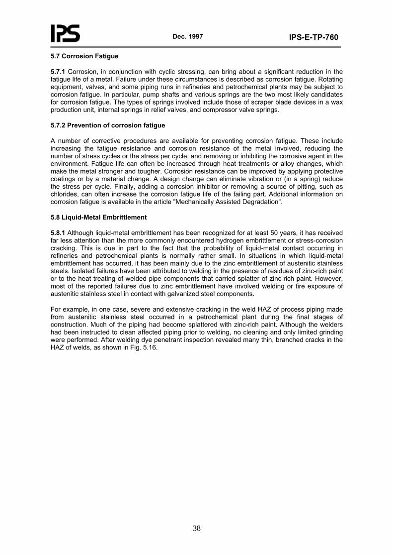
Dec. 1997
IPS-E-TP-760
38
5.7 Corrosion Fatigue
5.7.1 Corrosion, in conjunction with cyclic stressing, can bring about a significant reduction in the fatigue life of a metal. Failure under these circumstances is described as corrosion fatigue. Rotating equipment, valves, and some piping runs in refineries and petrochemical plants may be subject to corrosion fatigue. In particular, pump shafts and various springs are the two most likely candidates for corrosion fatigue. The types of springs involved include those of scraper blade devices in a wax production unit, internal springs in relief valves, and compressor valve springs.
5.7.2 Prevention of corrosion fatigue
A number of corrective procedures are available for preventing corrosion fatigue. These include increasing the fatigue resistance and corrosion resistance of the metal involved, reducing the number of stress cycles or the stress per cycle, and removing or inhibiting the corrosive agent in the environment. Fatigue life can often be increased through heat treatments or alloy changes, which make the metal stronger and tougher. Corrosion resistance can be improved by applying protective coatings or by a material change. A design change can eliminate vibration or (in a spring) reduce the stress per cycle. Finally, adding a corrosion inhibitor or removing a source of pitting, such as chlorides, can often increase the corrosion fatigue life of the failing part. Additional information on corrosion fatigue is available in the article "Mechanically Assisted Degradation".
5.8 Liquid-Metal Embrittlement
5.8.1 Although liquid-metal embrittlement has been recognized for at least 50 years, it has received far less attention than the more commonly encountered hydrogen embrittlement or stress-corrosion cracking. This is due in part to the fact that the probability of liquid-metal contact occurring in refineries and petrochemical plants is normally rather small. In situations in which liquid-metal embrittlement has occurred, it has been mainly due to the zinc embrittlement of austenitic stainless steels. Isolated failures have been attributed to welding in the presence of residues of zinc-rich paint or to the heat treating of welded pipe components that carried splatter of zinc-rich paint. However, most of the reported failures due to zinc embrittlement have involved welding or fire exposure of austenitic stainless steel in contact with galvanized steel components.
For example, in one case, severe and extensive cracking in the weld HAZ of process piping made from austenitic stainless steel occurred in a petrochemical plant during the final stages of construction. Much of the piping had become splattered with zinc-rich paint. Although the welders had been instructed to clean affected piping prior to welding, no cleaning and only limited grinding were performed. After welding dye penetrant inspection revealed many thin, branched cracks in the HAZ of welds, as shown in Fig. 5.16.
Dec. 1997
IPS-E-TP-760
39
INTERGRANULAR CRACKING IN HAZ OF STRINGER-BEAD WELD ON TYPE 304 (S30400)
STAINLESS STEEL PIPE DUE TO ZINC EMBRITTLEMENT. WELD AREA HAD BEEN COVERED WITH ZINC-RICH PAINT.
Fig. 5.16
In many cases, through-wall cracks cause leaks during hydro testing. Typically, zinc embrittlement cracks contain zinc rich precipitates on fracture surfaces and at the very end of the crack tip. Cracking is invariably intergranular in nature.
Zinc embrittlement is a relatively slow process that is controlled by the rate of zinc diffusion along austenitic grain boundaries. Zinc combines with nickel, and this results in nickel-depleted zones adjacent to the grain boundaries. The resulting transformation of face-centered cubic austenite (γ ) to body-centered cubic ferrite (α ) in this region is thought to produce not only a suitable diffusion path for zinc but also the necessary stresses for initiating intergranular cracking. Externally applied stresses accelerate cracking by opening prior cracks to liquid metal.
Although the melting point of zinc is 420°C (788°F), no zinc embrittlement has been observed at temperatures below 570°C (1380°F), probably because of phase transformation and diffusion limitations. There is no evidence that an upper temperature limit exists. In the case of zinc-rich paints, only those having metallic zinc powder as a principal component can cause zinc embrittlement of austenitic stainless steels. Paints containing zinc oxide or zinc chromates are known not to cause embrittlement.
5.8.2 Prevention of zinc embrittlement
Obviously, the best approach to the prevention of zinc embrittlement is to avoid or minimize zinc contamination of austenitic stainless steel components in the first place. In practice, this means using no galvanized structural steel, such as railings, ladders, walkways, or corrugated sheet metal, at locations where molten zinc is likely to drop on stainless steel components if a fire occurs. If zinc-rich paints will be used on structural steel components, shop priming is to be preferred. Field application of zinc-rich paints should be done after all welding of stainless steel components has been completed and after insulation has been applied. Otherwise, stainless steel components should be temporarily covered with plastic sheathing to prevent deposition of overspray and splatter.
If stainless steel components have become contaminated despite these precautionary measure, proper cleaning procedures must be implemented. Visible paint overspray should be removed by sandblasting, wire brushing, or grinding. The operations should be followed by acid pickling and
Dec. 1997
IPS-E-TP-760
40
water rinsing. Acid pickling will remove any traces of zinc that may have been smeared into the stainless steel surface by mechanical cleaning operations. Suitable acid pickling solutions include 5 to 10% nitric acid, phosphoric acid, or sulfuric acid. Hydrochloric acid should not be used in order to avoid potential pitting or SCC problems. After removal of all traces of acid by water rinsing, final cleaning with naphtha solvent should be performed immediately before welding.
5.9 Erosion-Corrosion
5.9.1 Various materials of construction for refinery and petrochemical plant service may exhibit accelerated metal loss under unusual fluid-flow conditions. Attack is caused by a combination of flow velocity (mechanical factors) and corrosion (electrochemical factors) known as erosion-corrosion. Affected metal surfaces will often contain grooves or wavelike marks that indicate a pattern of directional attack. Soft metals, such as copper and aluminum alloys, are often especially prone to erosion-corrosion, as are metals such as stainless steels, which depend on thin oxide films for corrosion protection. Most cases of erosion-corrosion can be mitigated by proper design and/or materiel changes. For example, by eliminating sharp bends, erosion-corrosion problems can be significantly reduced in process piping. Increasing the pipe diameter of vapor lines will reduce flow velocities and therefore the erosion-corrosion by impinging droplets of liquid. Piping immediately downstream of pressure letdown valves often must be upgraded to prevent accelerated attack due to high flow turbulence.
5.9.2 Cavitation
Cavitation damage is a fairly common form of erosion-corrosion of pumps impellers or hydraulic turbine internals. Cavitation is caused by collapsing gas bubbles at high-pressure locations; adjacent metal surfaces are damaged by the resultant hydraulic shock waves. Cavitation damage is usually in the form of loosely spaced pits that produce a roughened surface area. Subsurface metal shows evidence of mechanical deformation. As a general rule, cast alloys are likely to suffer more damage than wrought versions of the same alloy. Ductile materials, such as wrought austenitic stainless steels, have the best resistance to cavitations. Damage can be reduced by design changes, material changes, and the use of corrosion inhibitors. Smooth finishes on pump impellers will reduce damage. Some coatings can be beneficial. Design changes with the objective of reducing pressure gradients in the flowing liquid are most effective.
5.9.2.1 Mixed-phase flow
Accelerated corrosion due to mixed vapor/liquid streams is found primarily in crude and vacuum furnace headers and transfer lines of crude distillation units, in over-head vapor lines and condenser inlets on various fractionation towers, and in reactor effluent coolers of hydrocracking and hydrotreating units.
In general, increases in vapor load and mass velocity increase the severity of high-temperature sulfidic corrosion by crude oils and atmospheric residuum (reduced crude). Corrosion is least severe with flow regimes in which the metal surface is completely wetted with a substantial liquid hydrocarbon layer. Corrosion is most severe with the spray flow that results from vapor velocities above 60 m/s (200 ft/s) and vapor loads above 60%.
Under these conditions, corrosion rates of certain components, such as furnace headers, furnace-tube return bends, and piping elbows, could increase by as much as two orders of magnitude. This phenomenon is caused by droplet impingement, which destroys the protective sulfide scale normally found on steel components. Such impingement damage is usually not seen in straight piping, except immediately down-stream of circumferential welds. Damage is usually in the form of sharp-edged lake type corrosion that, because of its appearance, is often confused with naphthenic acid corrosion. As a rule, 5 Cr-0.5 Mo steel components have sufficient resistance to all but severe cases of droplet impingement in transfer lines. Higher alloys should be used for furnace tubes and associated components, such as headers and return bends.
Corrosion damage at elbows of overhead vapor lines is often caused by droplet impingement as a result of excessively high vapor velocities. Typical impingement-type corrosion of tubes and baffles
Dec. 1997
IPS-E-TP-760
41
just below the vapor inlet of overhead condensers. As a general rule, overhead vapor velocities should be kept below 7.5 m/s (25 ft/s) to minimize impingement-type corrosion. In addition, horizontal impingement baffles can be mounted just above the top tube row of overhead condensers.
Air-cooled reactor effluent coolers of hydrocracking ad hydrotreating units are also prone to impingement-type corrosion. Poor flow distribution through large banks of parallel air coolers can result in excessive flow velocities in some coolers, usually those in the center. The resulting low flow velocities in the outer coolers can cause deposition of ammonium sulfide and/or chloride in these coolers; this blocks the tubes and further increases velocities in the remaining air coolers. This problem is aggravated by low, nighttime air temperatures, which increase deposition problems. Installation of protective sleeves (ferrules) at the inlet tube end has helped to reduce attack in some cases; in others, it has only moved the area of attack to an area immediately downstream of the sleeves. Careful attention to proper flow distribution through redesign of the inlet headers is often the only way of controlling air cooler corrosion.
5.9.2.2 Entrained catalyst particles
Accelerated corrosion due to entrained catalyst particles can occur in the reaction and catalyst regeneration sections of catalytic cracking units. Refractory linings are required to provide protection against oxidation and high-temperature sulfidic corrosion, as well as erosion by catalyst particles, particularly in cyclones, risers, standpipes, and slide valves. Stellite hardfacing is used on some components to protect against erosion. When there are no erosion problems and when protective linings are impractical, austenitic stainless steels such as Type 304 (S30400) can be used. Cyclone dip legs, air rings, and other internals in the catalyst regenerator are usually made of Type 304 (S30400) stainless steel, as is piping for regenerator flue gas. The main fractionation tower is usually made of carbon steel, with the lower part lined with a ferritic or martensitic stainless steel containing 12% Cr such as Type 405 (S40500) or 410 (S41000). Slurry piping between the bottom of the main fractionation tower and the reactor may receive an additional corrosion allowance as protection against excessive erosion.
5.10 Corrosion Control
Corrosion control measures shall be implemented during the design stage of refineries and petrochemical plants. This includes:
- proper design (see 6);
- proper material selection (see also IPS-E-TP-740);
- proper process which involves reduced temperature, low concentration of critical corrosive species, reduced flow velocity, oxygen elimination, etc.;
- proper protective coatings and linings specially for refractories (see IPS-E-TP-100 and IPS-E-TP-350).
6. SYSTEMATIC ANALYSIS OF PROJECT
6.1 General
Where corrosion can interfere, the true functional purpose will not be achieved. Thus the concerned designer shall not concentrate purely on the functional aspects of design, to the total exclusion of other considerations, but must be aware that there are many ways in which corrosion can ruin even the best creation.
He shall acquaint himself with the basics of corrosion and shall be fully aware of his own power and opportunity to ease, retard or stop corrosion in a reasonable and economic way, by selective employment of qualified precautions or by optimal adjustment of his functional design. The corrosion-control measures he takes in his design need tactical, logistic and mainly logical support
Dec. 1997
IPS-E-TP-760
42
embodied in the design itself.
The designer shall appreciate both his technical formulae and also the corrosion which destroys the function of his product. All this knowledge shall be combined in a unified and orderly form of creation. Basically, the main effort in corrosion control is given to:
a) curative control-to cure corrosion after it has occurred;
b) preventive control-to prevent or delay corrosion and reduce its harmful effects by taking precautions in advance.
Preventive control deals with the followings:
- pre-production planning;
- specification of corrosion-control measures and selection of optimal materials;
- design forms;
- fabrication and treatment methods to suit the finite environment;
- conditions of employment.
Further, preventive control is concerned with putting these selected measures into effect prior to deployment of the designed structure or equipment and ultimately with the means of securing the appropriate quality of the product’s economically extended functionalism.
The cost and degree of efficiency of the embodied corrosion-control measures can be predetermined and their system varied to suit. The unexpected is more expensive than the planned and predicted. For this reason preventive control shall be the prime consideration of every designer. On the other hand, curative control of the designed utility must not be altogether forgotten and all newly designed products must be made ready for its probable deployment at any appropriate time.
6.2 Organization of Work
A thorough planning of working sequences and procedures is necessary to secure the requisite efficiency and smooth flow of applying corrosion control in design. Possible extent, sequencing and flow are indicated in a schematic diagram of corrosion control (Fig. 6.1.).
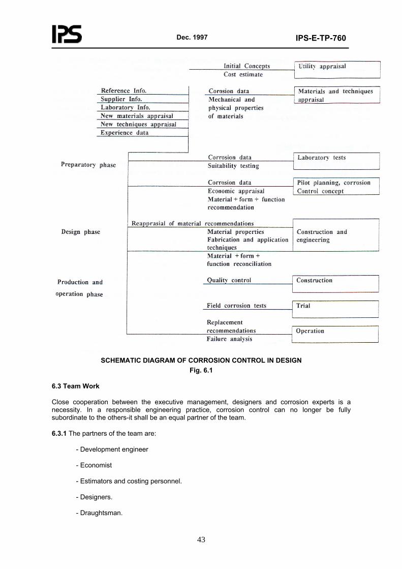
Dec. 1997
IPS-E-TP-760
43
SCHEMATIC DIAGRAM OF CORROSION CONTROL IN DESIGN
Fig. 6.1
6.3 Team Work
Close cooperation between the executive management, designers and corrosion experts is a necessity. In a responsible engineering practice, corrosion control can no longer be fully subordinate to the others-it shall be an equal partner of the team.
6.3.1 The partners of the team are:
- Development engineer
- Economist
- Estimators and costing personnel.
- Designers.
- Draughtsman.
Dec. 1997
IPS-E-TP-760
44
- Production control.
- Corrosion engineer.
- Laboratories and testing establishments.
- Industry related to corrosion data.
- Quality control organization.
The followings show what kind of co-operation these specialists can expect from any other member of his corrosion control team:
6.3.1.1 Development engineer
- Informs on overall corrosion involvement within the project utility.
- Informs on probable or possible environmental conditions and corrosion and ecological problems created by the product.
6.3.1.2 Economist
- Informs on broad spectrum evaluation of economic feasibility of the product, including its corrosion control.
- Instructs on cost limits for implementation of corrosion-control measures. In latter stages provides budgetary control to prevent corrosion control from running wild and to prevent unnecessary and excessive precautions.
6.3.1.3 Estimators and costing personnel
- Compute, financially evaluate, record and report continuously on the cost of anti-corrosion measures at all stages of the design work, to prevent waste.
6.3.1.4 Designers
- Study, consider, reconcile and embody into the design such corrosion-control precautions that materially do not interfere with the engineering function of the utility and serve the purpose of optimal upkeep of its economic function.
- Seek relevant information from corrosion specialists and other involved personnel and sources on matters of corrosion-control policy and details.
- Supply corrosion specialists with necessary data and allow access to their work for the purpose of study and constructive criticism.
- Amend, revise or modify their design to a reasonable degree to suit the demands of corrosion control (changes to be documented).
- Implement the design instructions with well-founded quality control rules on matters of corrosion prevention.
- Supply required data to budgetary control for costing and evaluation of corrosion prevention.
- Initiate procurement or contract documents assisting in optimal corrosion control.
- Secure compatibility and prevent corrosive interference within their design between items supplied from various sources.
Dec. 1997
IPS-E-TP-760
45
6.3.1.5 Draughtsman
- Study and correctly interpret corrosion-control instructions and involvement of guidance drawings, specifications and design and quality control instructions.
- Consult with corrosion specialists on inclusion of relative aspects of corrosion control in the working drawings, bills of materials and schedules in the best interest of preventing infusion of corrosion into the product to be fabricated.
- Co-operate with production control on adjustment of corrosion-prevention measures to suit both parties and amend working drawings and schedules accordingly.
- Supply necessary data to costing personnel.
- Assist corrosion specialist in evaluation of drafting work.
6.3.1.6 Production control
- Secure practical planning of corrosion-control measures to suit the design and the particular production methods and techniques, as well as the application facilities and procedures.
- Reconcile design with production.
6.3.1.7 Corrosion engineer
- Supplies up-to-date information and practical expert advice (discussions, evaluations, advisory worksheets, design instructions, proposals and specifications) on principles and good practices of corrosion control; on the nature and effect of corrosive environments; on structural, metallurgical, physical and mechanical properties of various materials relative to their rate of corrosion, on their availability, fabrication, welding, treatment, their optimum design form, method of application and effective saving in weight.
- Advises on substitutions, clad metals, weld overlays, metallizing, preservation systems, anodic and cathodic protection, environmental adjustment, etc.
- Acts as a cleaning house for corrosion information to feed it selectively to the design personnel; to foster their awareness and involvement in corrosion control. Participates in writing specifications, standards and recommended practices instructions on matters of corrosion-control affinity.
- In collaboration with laboratories, testing establishments and project officers investigates new corrosion-control materials, processes, equipment and methods consistent with good practices; generates new ideas and investigates changes in design, specifications and standards.
- Evaluates economy of individual precautions on demand.
- Correlates technical work of design and drawing offices with original corrosion-control specifications, design instructions, manuals, standards and rules of good husbandry in corrosion control; instructs and examines for correct incorporation of corrosion control in all design activities, including guidance and working drawings either in pictorial form or in notes, schedules and bills of materials.
- Assists in translation of corrosion aspects of drawings and specifications into practical working instructions to project and production engineers and represents corrosion-control interests in negotiations between the design office and production organization for sound inclusion of corrosion-control rules, specifications, instructions and quality control stipulations into production planning.
Dec. 1997
IPS-E-TP-760
46
- Collaborates with quality control organization on setting up of appropriate quality control procedures and on maintenance of quality assurance of corrosion-control precautions during design, drafting, production and trial activities.
- Represents management and design office on corrosion and failure committees for interpretation of applied corrosion-control measures and proposes revisions.
- Co-operates with ordering channels on corrosion-control suitability of bought-out items and contents of appropriate instructions contained in contracting documents.
6.3.1.8 Laboratories and testing establishments
- Report on pure research of corrosion phenomena and applied research of corrosion-control materials and methods.
- Test at various stages of the design program or on request the performance and suitability of materials and methods to assure optimum use, application and design form in the given conditions.
- Participate on pilot and trial runs for evaluation of efficiency or merit of tested corrosion-control precautions.
- Install and operate scientific testing and recording apparatus for evaluation of failures and non-destructive testing.
- Participate in quality assurance.
- Assist design organization in avoidance of guesswork in preparation of design and in establishing a more stable scientific basis for engineering decisions.
6.3.1.9 Industry, related to corrosion data
- Supplies accurate and complete corrosion data on their own products, methods, techniques and facilities. Collaborates on applied corrosion research and testing relevant to their products.
- Supplies correct materials and services in accordance with specifications, design, schedules and working drawings and maintain their uniform quality.
- Trains and supplies efficient advisory staff, approved applicators and site inspectors for securement of effective corrosion-control measures (materials and work) when arranged.
6.3.1.10 Quality control organization
- Assures that quality control measures are maintained on all levels of planning, design, drawing and fabrication.
- Plans and organizes quality control for individual corrosion-control systems and procedures.
- Composes written or drawn instructions and quality assurance specifications overall or in detail for individual tasks.
- Performs practical inspection in co-operation with laboratories and corrosion specialists.
- Indicates modes of enforcement of quality assurance.
Dec. 1997
IPS-E-TP-760
47
6.4 Sources of Information
Before project analysis can commence the basic common concepts of the project utility should be known to all personnel engaged both in functional design and corrosion-control work, as well as the basic philosophy of the utility complex and the principles of working and flow sequences of all mechanical, chemical and electronic components which constitute the utility.
Further, the design personnel should make a total effort to collect from all available sources accurate data and information relating to corrosion-control requirements of the project, in their most comprehensive form, to allow the designers to analyze and select proper measures and appreciate accurately their probabilities.
6.4.1 Environmental conditions
Environmental conditions is a thorough review of corrosive environment existing in oil, gas and petrochemical industries can be classified as follows:
6.4.1.1 Atmospheric environment
Atmospheric environment is defined under categories of dry, damp, humid, rural, industrial, coastal, municipal, etc.
Generally increase in humidity, temperature and the percentage of acid gases such as CO2, H2S, SO2, CO, Cl2 will increase its corrosivity (for more information see IPS-E-TP-100 and API Standard 571 7 580).
6.4.1.2 Natural waters
Corrosivity of natural waters depends on their constituents such as dissolved solids, gases and sometimes colloidal or suspended matters. The effect may be either one of stimulation or one of suppression the corrosion reaction. Constituents or impurities of water are dissolved gases such as oxygen, CO2, SO2, NH3, H2S which part of them are the results of bacteria activity.
Dissolved mineral salts are mostly calcium, magnesium sodium, bicarbonate, sulfate, chloride and nitrate. The effect of each of these ions on corrosion rate is different but briefly the chlorides have received the most study in this regard.
Organic contaminants of water directly can affect the corrosion rate of metals and alloys. Bacteria, under favorite conditions can be doubled in 10-60 minutes. This characteristics is typical of wide spread biodeterioration caused by microbes in all industries of which corrosion is a special case. With a few exceptions such as synthetics polymers, all materials can be attached by bacteria.
6.4.1.3 Sea water
Greatest attack on offshore structures occurs in the splash zone due to alternate wetting and drying and also aeration. In quite stagnant condition the effect of bacteria and pitting type corrosion are predominant. The rapid growth of marine fouling in the tropics may provide a protective shield which counteracts the effect of the greater activity of the hotter water.
6.4.1.4 Soils
Most of the industrial equipment in contact with soil or embedded underground will suffer corrosion. Increase in water content and decrease in pH and resistivity will enhance corrosivity of soil. For details see IPS-E-TP-820.
6.4.1.5 Chemicals
The chemical environments exist in refinery and mostly in petrochemical industries. Various chemicals are explained as follows:
Dec. 1997
IPS-E-TP-760
48
- Type and composition of chemical; physical state (solid, liquid, gaseous); toxicity; purity; concentration/- dilution; pH value; continuity and type of exposure (cycling, immersion, spillage, fumes); maximum and minimum temperatures; fluid velocity; aeration and oxygen content; effect of corrosion products on the chemical; catalytic effect; probability of osmosis; etc.
- To clarify all the chemical environments and suitable material, is impossible because of collating such a large amount of data. For example if some 400 systems are identified as being handled and processed on a large scale and there are 10 suitable materials, then 4000 systems would have to be considered. Since temperature concentration and solution velocity are important in determining corrosion rate, and if only five levels of each of the three variables are considered, then the number of environments to be considered would be 4000 × 53 = 600000. Therefore only those chemical environments which are corrosive and have a detrimental effect on material selection in oil, gas and petrochemical industries are briefly discussed.
6.4.1.6 Dry heat or cold exposure
Maximum and minimum temperature; temperature gradient; temperature spread; frequency of variations; hot spots; etc.
6.4.1.7 Abrasion exposure
Degree; duration; concentration; etc.
6.4.1.8 Microbiological influence
Type of microbial life; direct or indirect effect; medium; temperature; periodicity of exposure; etc.
6.4.1.9 Shock and vibration
Source; strength; frequency; concentration; transfer path; etc.
6.4.1.10 Atomic radiation
Type; exposure; continuity; temperature; etc.
6.4.1.11 Absorbent materials
Type (mortar, concrete, brick, floor compositions, wood, plastics, insulating and gasket materials, etc.); thickness; Ph value; consistency; porosity; evaporation rate; absorbence rate; conductivity and resistivity; etc.
6.4.2 Case histories and technical data records
Historically documented cases of corrosion behavior of the same or similar product and of the effectiveness of corrosion-control methods applied in similar environmental and operational circumstances are very useful for comparative evaluation of corrosion control in design. Such information however shall be studied and considered with caution, taking into account the possibility of many variations and combinations of conditions, from which errors and misconceptions could arise. Ultimately, each design case should be appreciated as unique and then no individual case history may be accepted as an unquestionable dictate.
6.4.2.1 Failure reports
The negative information contained in these documents shall be recorded in a comprehensive form (object, materials, fabrication, treatment, operational data, locality, description and cause of failure), evaluated either by corrosion experts or a failure board and filed for easy reference by all design personnel.
Dec. 1997
IPS-E-TP-760
49
The reports can either be filed individually or together. Where a number of failure reports on a related subject can accumulate, a corrosion failure index dealing with various sections of the problem or various parts of utility is preferred. Where a considerable number of failures of a comparatively restricted and repetitive nature is expected, it is desirable to record such information by electronic data processing. It is important that such information, in accurate form and preferably converted into a useful summary, be distributed as soon as possible to all interested personnel to be used either for design revision or maintenance programming.
6.4.2.2 Materials and treatment records
The positive information recorded in an index form, and accurately updated, can illustrate the whole development and progress of corrosion-control application in design of a particular project or its part and may become a source of valuable information for corrosion-control design analysis, specifications, working drawings, schedules, standards and procedures.
6.4.2.3 Reference file
No person engaged in corrosion control shall be without access to a filing system which covers accurately all corrosion control in his particular enterprise. The volume of information required is too extensive to memorize.
This can be achieved either by a well-organized personal file or through access to a large-scale or computerized filing system.
The volume of such a file, in so far as it depends on the extent of activities, shall not be static but altogether dynamic; it shall grow in size and utility with the demand and progress of corrosion science and art and be immediately usable to cover the need of the moment and so allow an easy literature search.
6.4.2.4 Comparative index
When the extent of the reference file becomes too unwieldy for a quick search, or where several materials of the same generic group are often evaluated for preferential use, a comparative index can prove of value.
6.4.2.5 Standards
Setting of IPS corrosion engineering standards helps the speeding up of design.
6.4.3 Analysis
Once the preparatory stage of corrosion-control work in design (i.e. setting up a suitable organization and assembling ample information) is complete, the design team may commence with a step-by-step appreciation and evaluation of corrosion-control data, requirements, rules and other relevant information in a suitable and systematic manner. The results of this analysis will be followed by a reconciliation of the arising corrosion-prevention ideas with the product of the designers’ functional engineering appreciation, in accordance with their merits. Finally an overall decision will be made and also a plan of action compatible with the requirements of a rational securement of the planned function, the utility’s economic life and the safety of the utility or its parts appointed.
One may however consider, after a detailed examination of the schematic design control analysis (Fig. 6.2) and the following individual sections, that by a total separation of the mentioned two efforts some work will be duplicated and valuable time wasted. Thus it may be left to the discretion of individual organizations in general or to necessities of individual projects in particular, whether by a judicious combination of items, at least in some of the opposing sections of analysis, a method of parallel thinking can be developed and unnecessary repetition avoided.
Each individual item of the two main parts of design analysis is important, by the degree of its merit

Dec. 1997
IPS-E-TP-760
50
for securement of the final results, and shall not be forgotten or neglected. For this reason the combined analytical effort shall be systematically suited to the project and systematically followed without fail.
One can mention here that the reasoning obtained by the corrosion-control analysis does not absolve the designer from implementing the basic engineering requirements vested in the utility itself, and a correct corrosion-control decision must not obstruct the product’s engineering function. Both of the mentioned efforts are, however, so closely knitted together that they shall be considered of equal importance, although on a selective basis.it is not good policy to consider only one branch of design analysis neglect the other.
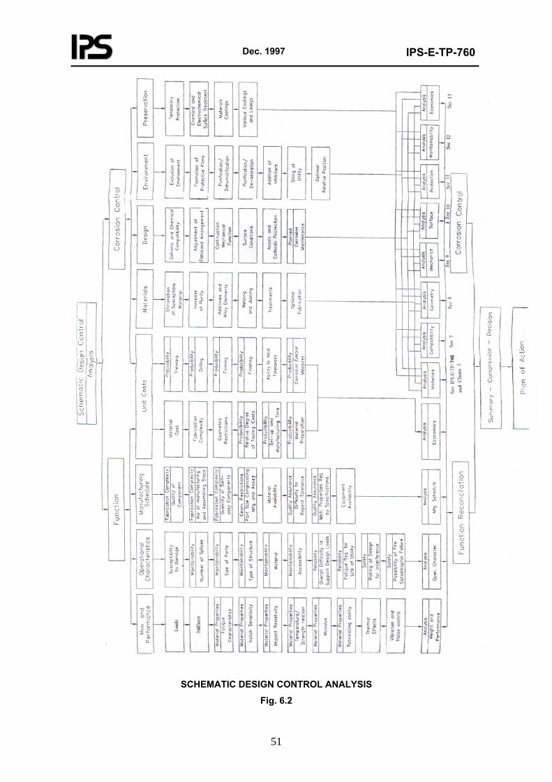
Dec. 1997
IPS-E-TP-760
51
SCHEMATIC DESIGN CONTROL ANALYSIS
Fig. 6.2
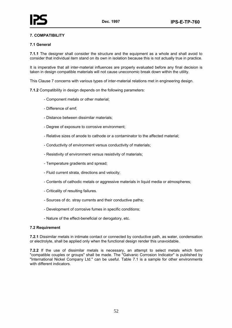
Dec. 1997
IPS-E-TP-760
52
7. COMPATIBILITY
7.1 General
7.1.1 The designer shall consider the structure and the equipment as a whole and shall avoid to consider that individual item stand on its own in isolation because this is not actually true in practice.
It is imperative that all inter-material influences are properly evaluated before any final decision is taken in design compatible materials will not cause uneconomic break down within the utility.
This Clause 7 concerns with various types of inter-material relations met in engineering design.
7.1.2 Compatibility in design depends on the following parameters:
- Component metals or other material;
- Difference of emf;
- Distance between dissimilar materials;
- Degree of exposure to corrosive environment;
- Relative sizes of anode to cathode or a contaminator to the affected material;
- Conductivity of environment versus conductivity of materials;
- Resistivity of environment versus resistivity of materials;
- Temperature gradients and spread;
- Fluid current strata, directions and velocity;
- Contents of cathodic metals or aggressive materials in liquid media or atmospheres;
- Criticality of resulting failures.
- Sources of dc. stray currents and their conductive paths;
- Development of corrosive fumes in specific conditions;
- Nature of the effect-beneficial or derogatory, etc.
7.2 Requirement
7.2.1 Dissimilar metals in intimate contact or connected by conductive path, as water, condensation or electrolyte, shall be applied only when the functional design render this unavoidable.
7.2.2 If the use of dissimilar metals is necessary, an attempt to select metals which form "compatible couples or groups" shall be made. The "Galvanic Corrosion Indicator" is published by "International Nickel Company Ltd." can be useful. Table 7.1 is a sample for other environments with different indicators.
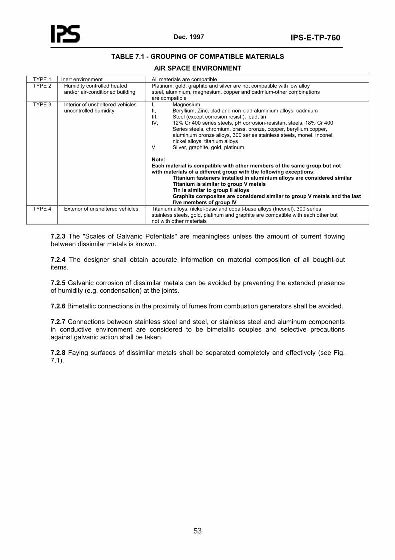
Dec. 1997
IPS-E-TP-760
53
TABLE 7.1 - GROUPING OF COMPATIBLE MATERIALS
AIR SPACE ENVIRONMENT TYPE 1 Inert environment All materials are compatible TYPE 2 Humidity controlled heated
and/or air-conditioned building Platinum, gold, graphite and silver are not compatible with low alloy steel, aluminium, magnesium, copper and cadmium-other combinations are compatible
TYPE 3 Interior of unsheltered vehicles uncontrolled humidity
I, Magnesium II, Beryllium, Zinc, clad and non-clad aluminium alloys, cadmium III, Steel (except corrosion resist.), lead, tin IV, 12% Cr 400 series steels, pH corrosion-resistant steels, 18% Cr 400 Series steels, chromium, brass, bronze, copper, beryllium copper, aluminium bronze alloys, 300 series stainless steels, monel, Inconel, nickel alloys, titanium alloys V, Silver, graphite, gold, platinum Note: Each material is compatible with other members of the same group but not with materials of a different group with the following exceptions: Titanium fasteners installed in aluminium alloys are considered similar Titanium is similar to group V metals Tin is similar to group II alloys Graphite composites are considered similar to group V metals and the last five members of group IV
TYPE 4 Exterior of unsheltered vehicles Titanium alloys, nickel-base and cobalt-base alloys (Inconel), 300 series stainless steels, gold, platinum and graphite are compatible with each other but not with other materials
7.2.3 The "Scales of Galvanic Potentials" are meaningless unless the amount of current flowing between dissimilar metals is known.
7.2.4 The designer shall obtain accurate information on material composition of all bought-out items.
7.2.5 Galvanic corrosion of dissimilar metals can be avoided by preventing the extended presence of humidity (e.g. condensation) at the joints.
7.2.6 Bimetallic connections in the proximity of fumes from combustion generators shall be avoided.
7.2.7 Connections between stainless steel and steel, or stainless steel and aluminum components in conductive environment are considered to be bimetallic couples and selective precautions against galvanic action shall be taken.
7.2.8 Faying surfaces of dissimilar metals shall be separated completely and effectively (see Fig. 7.1).
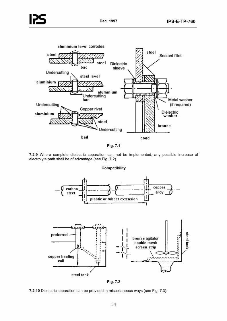
Dec. 1997
IPS-E-TP-760
54
Fig. 7.1
7.2.9 Where complete dielectric separation can not be implemented, any possible increase of electrolyte path shall be of advantage (see Fig. 7.2).
Compatibility
Fig. 7.2
7.2.10 Dielectric separation can be provided in miscellaneous ways (see Fig. 7.3):
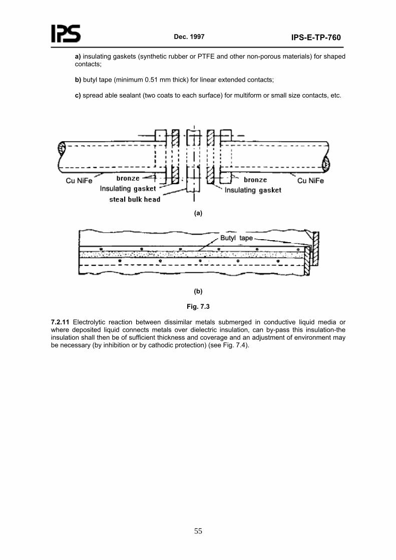
Dec. 1997
IPS-E-TP-760
55
a) insulating gaskets (synthetic rubber or PTFE and other non-porous materials) for shaped contacts;
b) butyl tape (minimum 0.51 mm thick) for linear extended contacts;
c) spread able sealant (two coats to each surface) for multiform or small size contacts, etc.
(a)
(b)
Fig. 7.3
7.2.11 Electrolytic reaction between dissimilar metals submerged in conductive liquid media or where deposited liquid connects metals over dielectric insulation, can by-pass this insulation-the insulation shall then be of sufficient thickness and coverage and an adjustment of environment may be necessary (by inhibition or by cathodic protection) (see Fig. 7.4).
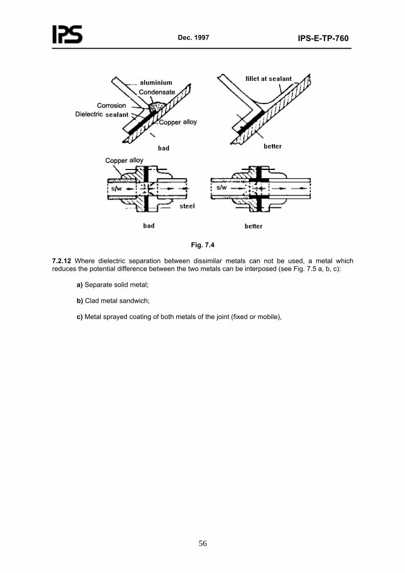
Dec. 1997
IPS-E-TP-760
56
Fig. 7.4
7.2.12 Where dielectric separation between dissimilar metals can not be used, a metal which reduces the potential difference between the two metals can be interposed (see Fig. 7.5 a, b, c):
a) Separate solid metal;
b) Clad metal sandwich;
c) Metal sprayed coating of both metals of the joint (fixed or mobile),
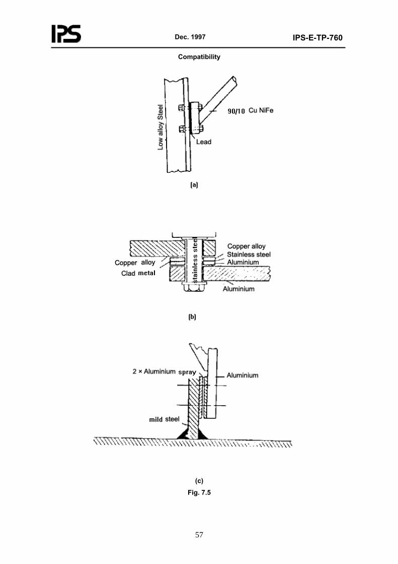
Dec. 1997
IPS-E-TP-760
57
Compatibility
(c)
Fig. 7.5
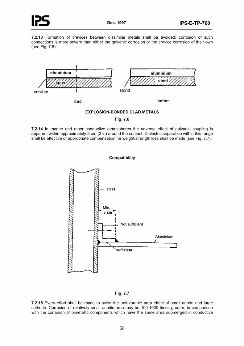
Dec. 1997
IPS-E-TP-760
58
7.2.13 Formation of crevices between dissimilar metals shall be avoided; corrosion of such connections is more severe than either the galvanic corrosion or the crevice corrosion of their own (see Fig. 7.6).
EXPLOSION-BONDED CLAD METALS
Fig. 7.6
7.2.14 In marine and other conductive atmospheres the adverse effect of galvanic coupling is apparent within approximately 5 cm (2 in) around the contact. Dielectric separation within this range shall be effective or appropriate compensation for weight/strength loss shall be made (see Fig. 7.7).
Compatibility
Fig. 7.7
7.2.15 Every effort shall be made to avoid the unfavorable area effect of small anode and large cathode. Corrosion of relatively small anodic area may be 100-1000 times greater, in comparison with the corrosion of bimetallic components which have the same area submerged in conductive
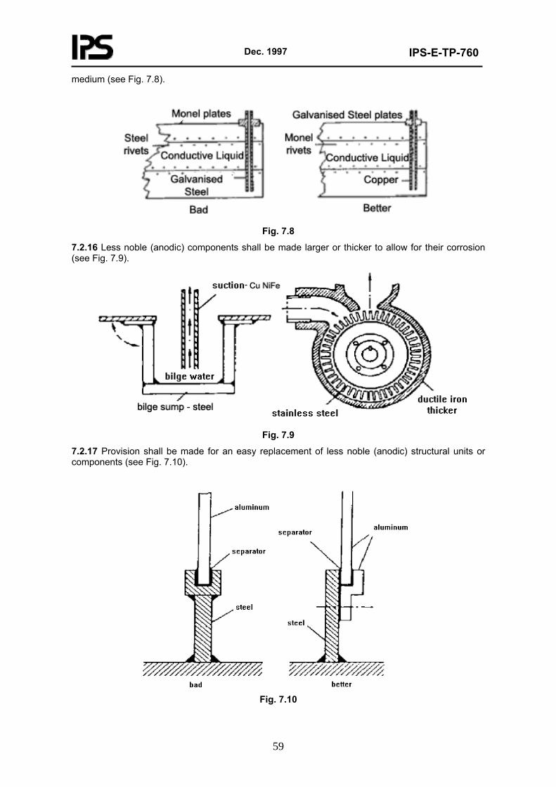
Dec. 1997
IPS-E-TP-760
59
medium (see Fig. 7.8).
Fig. 7.8
7.2.16 Less noble (anodic) components shall be made larger or thicker to allow for their corrosion (see Fig. 7.9).
Fig. 7.9
7.2.17 Provision shall be made for an easy replacement of less noble (anodic) structural units or components (see Fig. 7.10).
Fig. 7.10
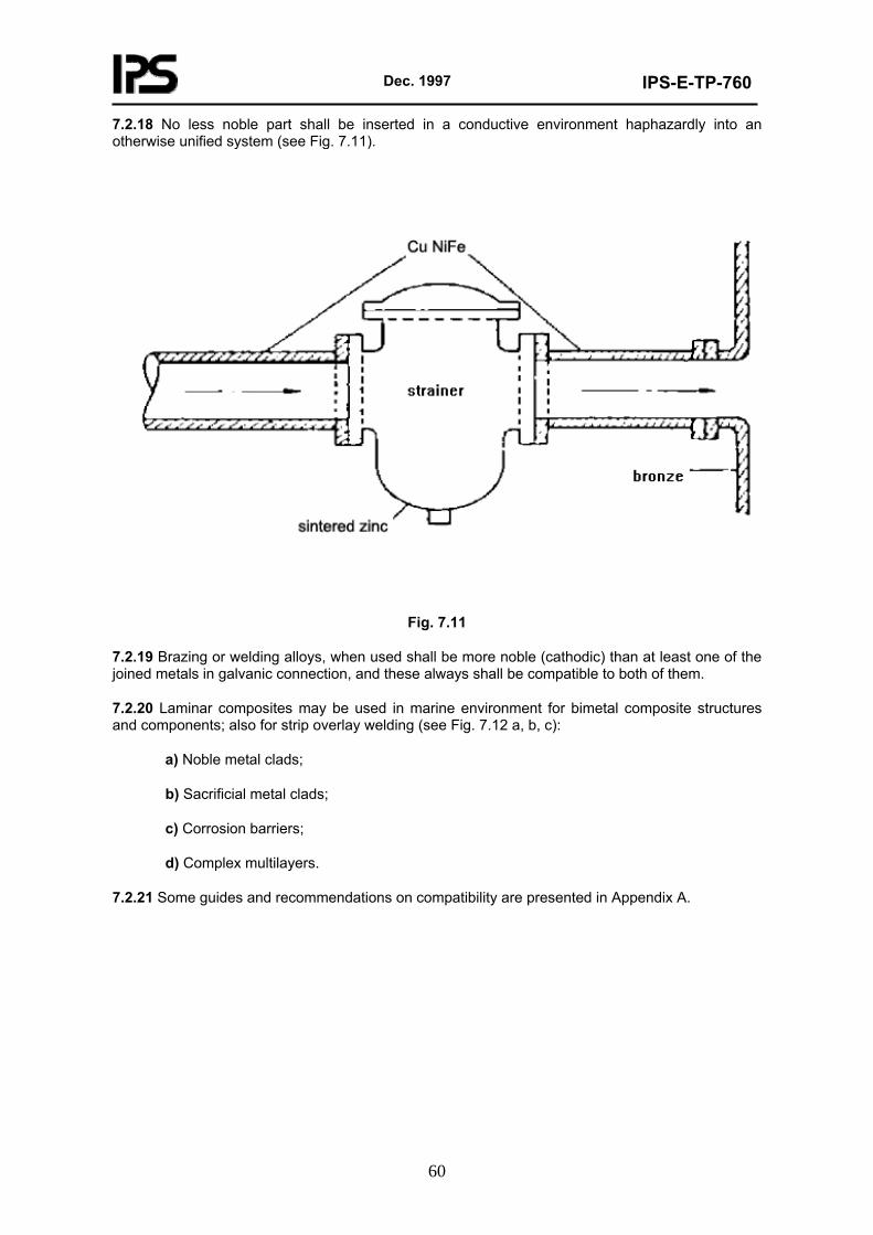
Dec. 1997
IPS-E-TP-760
60
7.2.18 No less noble part shall be inserted in a conductive environment haphazardly into an otherwise unified system (see Fig. 7.11).
Fig. 7.11
7.2.19 Brazing or welding alloys, when used shall be more noble (cathodic) than at least one of the joined metals in galvanic connection, and these always shall be compatible to both of them.
7.2.20 Laminar composites may be used in marine environment for bimetal composite structures and components; also for strip overlay welding (see Fig. 7.12 a, b, c):
a) Noble metal clads;
b) Sacrificial metal clads;
c) Corrosion barriers;
d) Complex multilayers.
7.2.21 Some guides and recommendations on compatibility are presented in Appendix A.
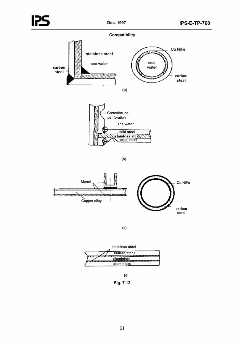
Dec. 1997
IPS-E-TP-760
61
Compatibility
Fig. 7.12
Dec. 1997
IPS-E-TP-760
62
8. SHAPE OR GEOMETRY
8.1 General
The embodiment of corrosion control into the design of a product can be achieved most efficiently by captivating this control within the product’s geometry, i.e. in its three-dimensional form, its layout and its relative and spatial positions. There is no other design effort which can assist so much in prevention of corrosion for such a comparatively small outlay.
Whereas basically the pattern of a utility depends on its functional, material and fabrication requirements, it is within the scope of a good designer to select from the available possibilities only such geometric shapes or combinations of forms that help to reduce corrosion attack in the most efficient and economic manner.
8.2 Requirement
8.2.1 The geometry of the designed component shall not only be appreciated within the narrowly defined lines of the component itself, in its own splendid isolation; its interdependence with other components within the system, within the utility and the space generally shall also be considered.
8.2.2 The appreciated form shall not be viewed rigidly from any one obvious aspect, the natural one to a respective designer, but from all sides, i.e. including the blind one.
8.2.3 Excessive complexity shall be avoided; design shall be simple, sleek and streamlined.
8.2.4 All environmental and functional conditions shall be made as uniform as possible throughout the entire design system by application of selective geometry.
8.2.5 The outside and inside geometric form, including the layout and general location, shall facilitate the product being kept clean and corrosion free at all stages of fabrication, assembly and during service-based on normal operation and breakdown conditions-without excessive effort.
8.2.6 The design shall prevent the adverse corrosive influence of one component of the utility on another in various media, due to spillage, emission of fumes or vapor, thermal and chemical effects, transfer of corrosive matter, formation of hot spots, etc., within the selected pattern.
8.2.7 Where water can be deposited by rain, spray or condensation, all reasonable design precautions should be taken to provide free access of drying air to the wetted surfaces. Fast drying of such surfaces shall be secured primarily by an appropriate selection of individual shapes, as well as by their proper combination and attachment.
8.2.8 Shapes which, contrary to their function, retain corrosive combinations of air and electrolyte should be avoided. The designed product shall neither collect nor retain unwelcome compound corrosive media within their form and frame.
8.2.9 Access and retention of unwelcome solid contaminants or wastes, which may act within the designed form by their absorbence and retention of moisture or their abrasive action, should be avoided by selected form and arrangement.
8.2.10 The geometry of the product shall be designed for exclusion or inclusion of oxygen, as relevant to the requirements of the particular construction material (e.g. active/passive metals require oxygen for the build-up of protective film; corrosion of other metals or alloys is aggravated by the presence of oxygen).
8.2.11 Design forms shall be chosen which lessen the effect or reduce the occurrence of such types of corrosion which depend directly or indirectly on the geometry of the product for their occurrence and degree of aggressiveness.
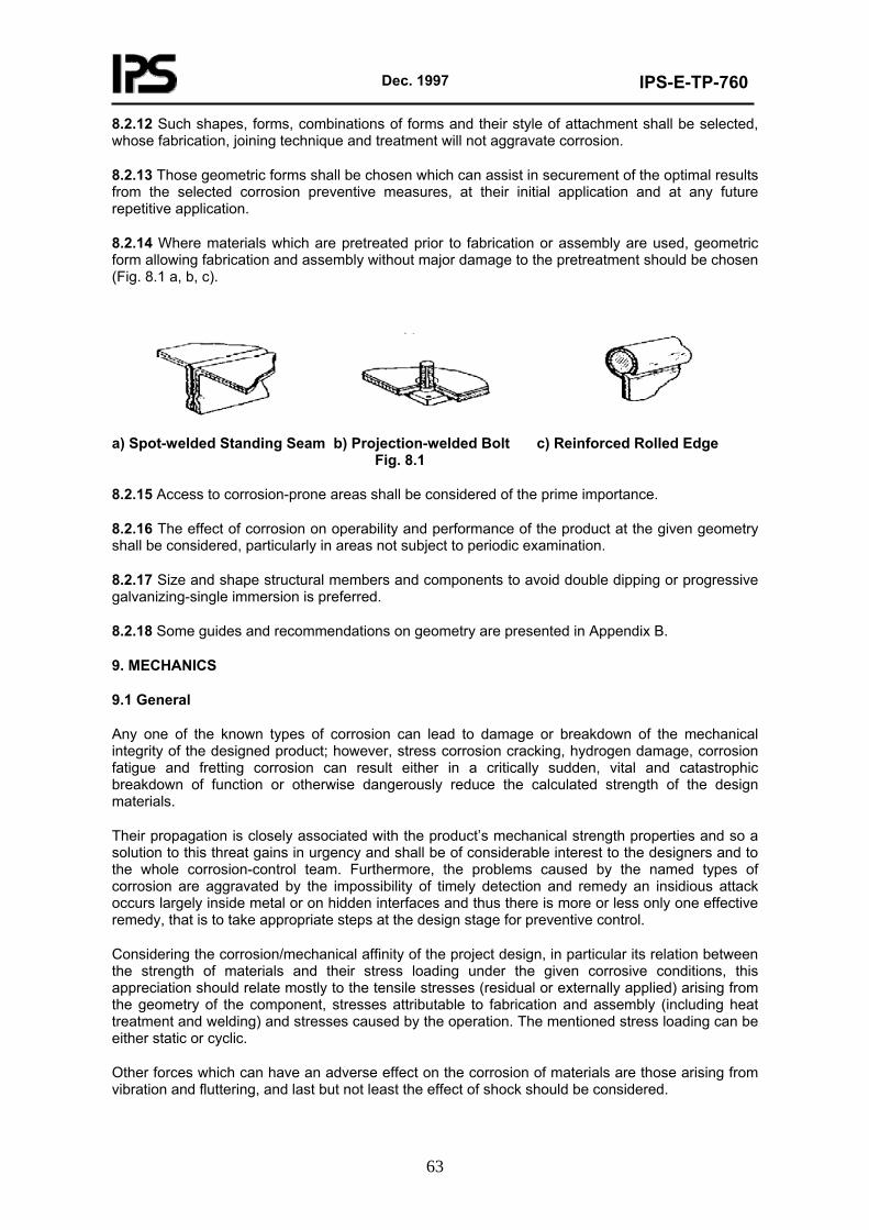
Dec. 1997
IPS-E-TP-760
63
8.2.12 Such shapes, forms, combinations of forms and their style of attachment shall be selected, whose fabrication, joining technique and treatment will not aggravate corrosion.
8.2.13 Those geometric forms shall be chosen which can assist in securement of the optimal results from the selected corrosion preventive measures, at their initial application and at any future repetitive application.
8.2.14 Where materials which are pretreated prior to fabrication or assembly are used, geometric form allowing fabrication and assembly without major damage to the pretreatment should be chosen (Fig. 8.1 a, b, c).
a) Spot-welded Standing Seam b) Projection-welded Bolt c) Reinforced Rolled Edge Fig. 8.1
8.2.15 Access to corrosion-prone areas shall be considered of the prime importance.
8.2.16 The effect of corrosion on operability and performance of the product at the given geometry shall be considered, particularly in areas not subject to periodic examination.
8.2.17 Size and shape structural members and components to avoid double dipping or progressive galvanizing-single immersion is preferred.
8.2.18 Some guides and recommendations on geometry are presented in Appendix B.
9. MECHANICS
9.1 General
Any one of the known types of corrosion can lead to damage or breakdown of the mechanical integrity of the designed product; however, stress corrosion cracking, hydrogen damage, corrosion fatigue and fretting corrosion can result either in a critically sudden, vital and catastrophic breakdown of function or otherwise dangerously reduce the calculated strength of the design materials.
Their propagation is closely associated with the product’s mechanical strength properties and so a solution to this threat gains in urgency and shall be of considerable interest to the designers and to the whole corrosion-control team. Furthermore, the problems caused by the named types of corrosion are aggravated by the impossibility of timely detection and remedy an insidious attack occurs largely inside metal or on hidden interfaces and thus there is more or less only one effective remedy, that is to take appropriate steps at the design stage for preventive control.
Considering the corrosion/mechanical affinity of the project design, in particular its relation between the strength of materials and their stress loading under the given corrosive conditions, this appreciation should relate mostly to the tensile stresses (residual or externally applied) arising from the geometry of the component, stresses attributable to fabrication and assembly (including heat treatment and welding) and stresses caused by the operation. The mentioned stress loading can be either static or cyclic.
Other forces which can have an adverse effect on the corrosion of materials are those arising from vibration and fluttering, and last but not least the effect of shock should be considered.
Dec. 1997
IPS-E-TP-760
64
Neither of the mentioned corrosion attacks has been ultimately defined by research and, where a critical design or materials are being considered, their suitability testing in a laboratory or as a pilot project is recommended. Generally it may be said that, given the right environment, none of the metals or alloys used is completely free of the danger of stress corrosion except, perhaps, those in pure from. Some of the most susceptible alloys are those normally selected for highly loaded and critical applications, and it is known that present-day demands on the available strength of materials are supporting this trend. Many failures attributed to fatigue of metals, overloading or other physical causes are, in fact, caused by stress corrosion.
Non-metallic materials also suffer from phenomena similar to stress corrosion, e.g., the presence of moisture lowers the strength of glass, stressed plastics crack when exposed to specific organic solvents, etc.
The analysis of corrosion associated with mechanical strength will be naturally in very close relation to the appreciation of the prime engineering function and optimalization of the designed product. Furthermore, one can qualify it as a functional analysis with a slant towards corrosion-control appreciation. Mechanical fault can initiate or aggravate corrosion incidence and corrosion per se can initiate or cause catastrophic failure.
Whilst an engineering product can fail due to stress, fatigue or friction in a benign corrosion environment, unless absolute perfection has been reached in design and fabrication through strict attention to the good practices of secure mechanical design, these optimal conditions are only very rarely obtained in general practice. It is truly advisable to pursue the sound policy of parallel appreciation of functional engineering and corrosion-control parameters by mutual consultancy to secure a safe product.
9.2 Requirements
9.2.1 Materials, stress level, environment, service temperature and design life are important parameters and shall be considered in every design.
9.2.2 Stress corrosion cracking is affected only by tensile stresses (residual or externally applied) purely compressive stresses do not cause stress corrosion cracking. No stress corrosion cracking shall occur at elastic stresses.
9.2.3 Select correct materials (see IPS-E-TP-740). If possible metals and alloys susceptible to stress corrosion or corrosion fatigue shall not be specified for highly loaded and critical structures and equipment in malignant corrosive environment.
9.2.4 Preference shall be given to materials which are resistant both to intergranular and stress corrosion, especially for applications involving residual and induced stresses. Alloys which are normally most resistant to intergranular corrosion are also more resistant to stress corrosion.
9.2.5 Avoid metals subject to hydrogen embrittlement in critical structures and equipment.
9.2.6 Any selection of dissimilar metal couples, if absolutely necessary, shall be confined to compatible couples in environments leading to stress corrosion cracking, corrosion fatigue and fretting corrosion.
9.2.7 Within the requirements of the economic life of the product, specify for adequate control of heat treating and metal working processes to develop microstructure optimally resistant to specific environment.
9.2.8 All bending, forming and shaping shall preferably be performed on metal in an annealed condition and every effort made to use the lowest practicable stress level.
9.2.9 Specify metal working, heat treating, flame and induction hardening, case hardening, carburising and nitriding (grain size refinement, metallurgical phase transformation, strain and dispersion hardening), whichever is required for increase of local strength or for improvement of
Dec. 1997
IPS-E-TP-760
65
fatigue strength or for introduction of compressive residual stresses into one or both of the rubbing surfaces.
9.2.10 Carbide solution treatment of corrosion-resistant steels shall be specified to minimize their sensitivity to intergranular corrosion. Specify suitable stress relieving (heat treatment, surface treatment, ultrasonic oscillators).
9.2.11 Select welding techniques that can produce sound welds. Defects (selective precipitation of phases, gas pockets, laps, undercutting, non-metallic inclusions, metallic alloying with prefabrication primers and other surface coatings, fissures and cracks) can act as sites of high residual tensile stress and thus lower the corrosion resistance.
9.2.12 The chemical and metallurgical composition of welding rods shall be compatible with the base metals, especially in the case of high strength metals.
9.2.13 Select and specify appropriate welding rods and welding techniques that will not cause hydrogen embrittlement of high strength metals.
9.2.14 Careful and optimal preparation and finishing of welds for stressed structures and equipment is imperative.
For prevention of stress corrosion cracking observe the precautions.
9.2.15 Preventive measures on stress corrosion cracking:
- Minimize applied or residual tensile stresses.
- Secure sufficient flexibility.
- Increase size of critical sections.
- Reduce stress concentration or redistribute stress.
- Compensate for loss of stiffness produced by penetration.
- Avoid misalignment of sections joined by riveting, bolting and welding.
- Design simple joints under stress. Avoid lap welding, riveting, bolting. But or fillet welding is preferred.
- Specify for stressed structures techniques that produce sound welds; also careful preparation and finishing of welds.
- Specify and design for elimination of stress raisers.
- Select suitable material (metallurgical composition).
- Avoid specifying any machining, assembling or welding operations which impart residual tensile stresses.
- Use materials in assembly with similar coefficient of expansion.
- Secure control of heat treatment and metal working to develop resistant microstructure.
- Specify input of compressive surface stresses by suitable treatments.
- Specify electroplating or metallising in stressed areas.
- Select suitable surface coatings. Specify passive surface films, suitable organic coatings
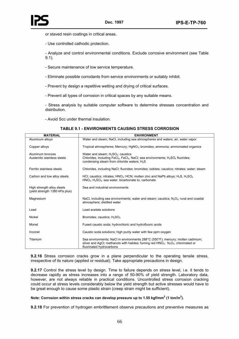
Dec. 1997
IPS-E-TP-760
66
or staved resin coatings in critical areas.
- Use controlled cathodic protection.
- Analyze and control environmental conditions. Exclude corrosive environment (see Table 9.1).
- Secure maintenance of low service temperature.
- Eliminate possible corrodants from service environments or suitably inhibit.
- Prevent by design a repetitive wetting and drying of critical surfaces.
- Prevent all types of corrosion in critical spaces by any suitable means.
- Stress analysis by suitable computer software to determine stresses concentration and distribution.
- Avoid Scc under thermal insulation.
TABLE 9.1 - ENVIRONMENTS CAUSING STRESS CORROSION MATERIAL ENVIRONMENT
Aluminum alloys Copper alloys Aluminum bronzes Austenitic stainless steels Ferritic stainless steels Carbon and low alloy steels High strength alloy steels (yield strength 1380 kPa plus) Magnesium Lead Nickel Monel Inconel Titanium
Water and steam; NaCl, including sea atmospheres and waters; air, water vapor Tropical atmospheres; Mercury; HgNO3; bromides; ammonia; ammoniated organics Water and steam; H2SO4; caustics Chlorides, including FeCl2, FeCl3, NaCl; sea environments; H2SO4 fluorides; condensing steam from chloride waters; H2S Chlorides, including NaCl; fluorides; bromides; iodides; caustics; nitrates; water; steam HCl; caustics; nitrates; HNO3; HCN; molten zinc and NaPb alloys; H2S, H2SO4 HNO3; H2SO4; sea water, bicarbonate to, carbonate Sea and industrial environments NaCl, including sea environments; water and steam; caustics; N2O4; rural and coastal atmosphere; distilled water Lead acetate solutions Bromides; caustics; H2SO4 Fused caustic soda; hydrochloric and hydrofluoric acids Caustic soda solutions; high purity water with few ppm oxygen Sea environments; NaCl in environments 288°C (550°F); mercury; molten cadmium; silver and AgCl; methanols with halides; fuming red HNO3; N2O4; chlorinated or fluorinated hydrocarbons
9.2.16 Stress corrosion cracks grow in a plane perpendicular to the operating tensile stress, irrespective of its nature (applied or residual). Take appropriate precautions in design.
9.2.17 Control the stress level by design. Time to failure depends on stress level, i.e. it tends to decrease rapidly as stress increases into a range of 50-90% of yield strength. Laboratory data, however, are not always reliable in practical conditions. Uncontrolled stress corrosion cracking could occur at stress levels considerably below the yield strength but active stresses would have to be great enough to cause some plastic strain (creep strain might be sufficient).
Note: Corrosion within stress cracks can develop pressure up to 1.55 kgf/mm2 (1 ton/in2).
9.2.18 For prevention of hydrogen embrittlement observe precautions and preventive measures as
Dec. 1997
IPS-E-TP-760
67
follows:
9.2.18.1 Select a clean metal.
9.2.18.2 Select a resistant material-homogeneous or clad.
9.2.18.3 Select low hydrogen welding electrodes and specify welding in dry conditions.
9.2.18.4 Select correct surface preparation and treatment.
9.2.18.5 Avoid incorrect pickling and plating procedures.
9.2.18.6 Metallize with resistant metal, or use a clad metal.
9.2.18.7 Induce compressive stresses.
9.2.18.8 Remove hydrogen from metal by baking 93-149°C; (200-300°F).
9.2.18.9 Provide for control of media chemistry (e.g. use inhibitors, remove sulphides, arsenic compounds, cyanides and phosphorus-containing ions from environment).
9.2.18.10 Control cathodic protection potential.
9.2.18.11 Specify impervious protective coating (e.g. rubber, plastic).
9.2.18.12 Avoid anodic metallic coatings.
9.2.19 For prevention of corrosion fatigue observe precautions and preventive measures as follows:
- Minimize or eliminate cyclic stressing.
- Increase size, bulk or local strength of critical sections.
- Reduce stress concentration or redistribute stress.
- Streamline fillet design for decrease of stress concentration and improvement of stress flow.
- Select the correct shape of critical sections.
- Size components by exchange of useless material in non-critical components for stronger critical sections.
- Provide for sufficient flexibility to reduce overstressing by thermal expansion. Vibration, shock and working of the structure or equipment.
- Provide against rapid changes of loading, temperature or pressure.
- Avoid fluttering and vibration-producing or vibration-transmitting design.
- Increase natural frequency for reduction of resonance corrosion fatigue.
- Improve ductility and impact strength.
- Specify stress relieve by heat treatment or by shot peening, Swaging, rolling, vapour blasting, tumbling, etc., to induce compressive stresses.
- Specify suitable surface finish.
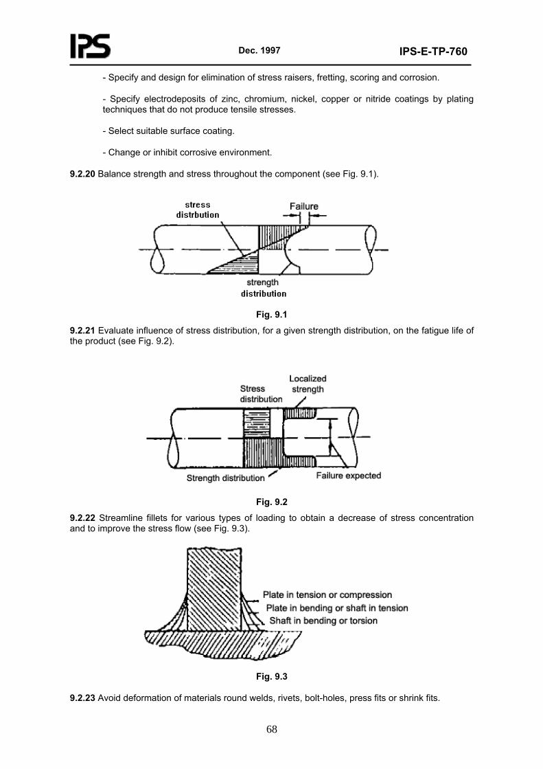
Dec. 1997
IPS-E-TP-760
68
- Specify and design for elimination of stress raisers, fretting, scoring and corrosion.
- Specify electrodeposits of zinc, chromium, nickel, copper or nitride coatings by plating techniques that do not produce tensile stresses.
- Select suitable surface coating.
- Change or inhibit corrosive environment.
9.2.20 Balance strength and stress throughout the component (see Fig. 9.1).
Fig. 9.1
9.2.21 Evaluate influence of stress distribution, for a given strength distribution, on the fatigue life of the product (see Fig. 9.2).
Fig. 9.2
9.2.22 Streamline fillets for various types of loading to obtain a decrease of stress concentration and to improve the stress flow (see Fig. 9.3).
Fig. 9.3
9.2.23 Avoid deformation of materials round welds, rivets, bolt-holes, press fits or shrink fits.
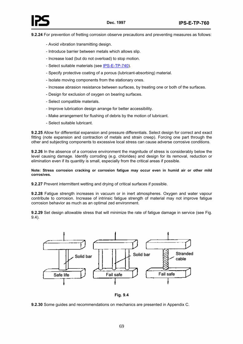
Dec. 1997
IPS-E-TP-760
69
9.2.24 For prevention of fretting corrosion observe precautions and preventing measures as follows:
- Avoid vibration transmitting design.
- Introduce barrier between metals which allows slip.
- Increase load (but do not overload) to stop motion.
- Select suitable materials (see IPS-E-TP-740).
- Specify protective coating of a porous (lubricant-absorbing) material.
- Isolate moving components from the stationary ones.
- Increase abrasion resistance between surfaces, by treating one or both of the surfaces.
- Design for exclusion of oxygen on bearing surfaces.
- Select compatible materials.
- Improve lubrication design arrange for better accessibility.
- Make arrangement for flushing of debris by the motion of lubricant.
- Select suitable lubricant.
9.2.25 Allow for differential expansion and pressure differentials. Select design for correct and exact fitting (note expansion and contraction of metals and strain creep). Forcing one part through the other and subjecting components to excessive local stress can cause adverse corrosive conditions.
9.2.26 In the absence of a corrosive environment the magnitude of stress is considerably below the level causing damage. Identify corroding (e.g. chlorides) and design for its removal, reduction or elimination even if its quantity is small, especially from the critical areas if possible.
Note: Stress corrosion cracking or corrosion fatigue may occur even in humid air or other mild corrosives.
9.2.27 Prevent intermittent wetting and drying of critical surfaces if possible.
9.2.28 Fatigue strength increases in vacuum or in inert atmospheres. Oxygen and water vapour contribute to corrosion. Increase of intrinsic fatigue strength of material may not improve fatigue corrosion behavior as much as an optimal zed environment.
9.2.29 Set design allowable stress that will minimize the rate of fatigue damage in service (see Fig. 9.4).
Fig. 9.4
9.2.30 Some guides and recommendations on mechanics are presented in Appendix C.
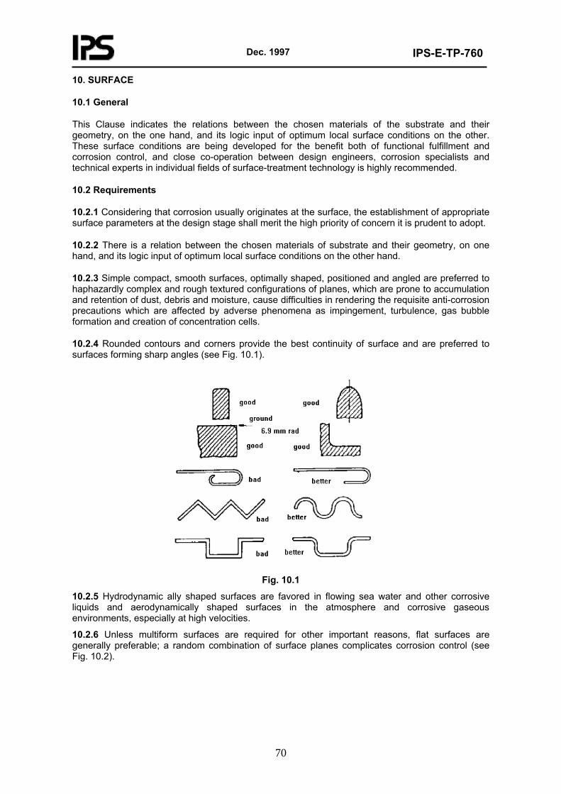
Dec. 1997
IPS-E-TP-760
70
10. SURFACE
10.1 General
This Clause indicates the relations between the chosen materials of the substrate and their geometry, on the one hand, and its logic input of optimum local surface conditions on the other. These surface conditions are being developed for the benefit both of functional fulfillment and corrosion control, and close co-operation between design engineers, corrosion specialists and technical experts in individual fields of surface-treatment technology is highly recommended.
10.2 Requirements
10.2.1 Considering that corrosion usually originates at the surface, the establishment of appropriate surface parameters at the design stage shall merit the high priority of concern it is prudent to adopt.
10.2.2 There is a relation between the chosen materials of substrate and their geometry, on one hand, and its logic input of optimum local surface conditions on the other hand.
10.2.3 Simple compact, smooth surfaces, optimally shaped, positioned and angled are preferred to haphazardly complex and rough textured configurations of planes, which are prone to accumulation and retention of dust, debris and moisture, cause difficulties in rendering the requisite anti-corrosion precautions which are affected by adverse phenomena as impingement, turbulence, gas bubble formation and creation of concentration cells.
10.2.4 Rounded contours and corners provide the best continuity of surface and are preferred to surfaces forming sharp angles (see Fig. 10.1).
Fig. 10.1
10.2.5 Hydrodynamic ally shaped surfaces are favored in flowing sea water and other corrosive liquids and aerodynamically shaped surfaces in the atmosphere and corrosive gaseous environments, especially at high velocities.
10.2.6 Unless multiform surfaces are required for other important reasons, flat surfaces are generally preferable; a random combination of surface planes complicates corrosion control (see Fig. 10.2).
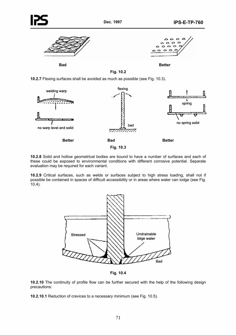
Dec. 1997
IPS-E-TP-760
71
Bad Better
Fig. 10.2
10.2.7 Flexing surfaces shall be avoided as much as possible (see Fig. 10.3).
Better Bad Better
Fig. 10.3
10.2.8 Solid and hollow geometrical bodies are bound to have a number of surfaces and each of these could be exposed to environmental conditions with different corrosive potential. Separate evaluation may be required for each variant.
10.2.9 Critical surfaces, such as welds or surfaces subject to high stress loading, shall not if possible be contained in spaces of difficult accessibility or in areas where water can lodge (see Fig. 10.4).
Fig. 10.4
10.2.10 The continuity of profile flow can be further secured with the help of the following design precautions:
10.2.10.1 Reduction of crevices to a necessary minimum (see Fig. 10.5).
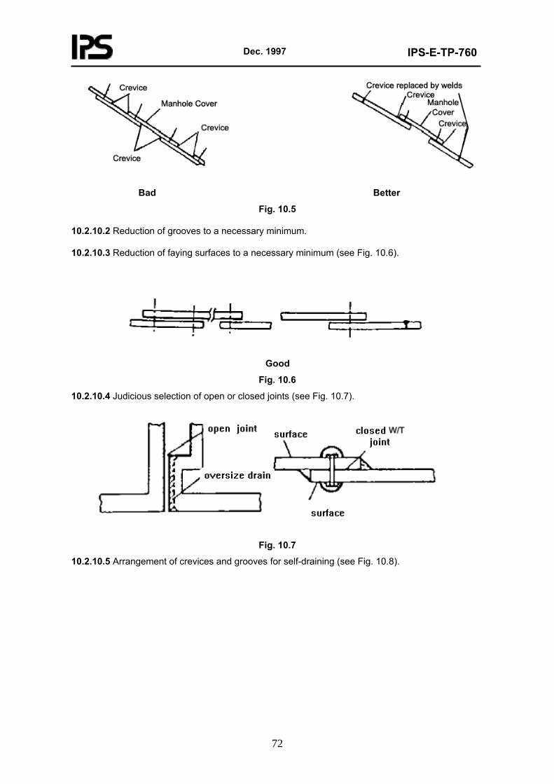
Dec. 1997
IPS-E-TP-760
72
Bad Better
Fig. 10.5
10.2.10.2 Reduction of grooves to a necessary minimum.
10.2.10.3 Reduction of faying surfaces to a necessary minimum (see Fig. 10.6).
Good
Fig. 10.6
10.2.10.4 Judicious selection of open or closed joints (see Fig. 10.7).
Fig. 10.7
10.2.10.5 Arrangement of crevices and grooves for self-draining (see Fig. 10.8).
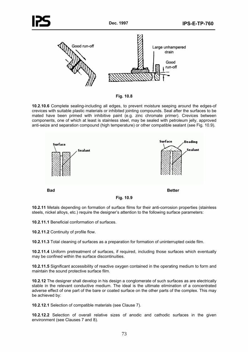
Dec. 1997
IPS-E-TP-760
73
Fig. 10.8
10.2.10.6 Complete sealing-including all edges, to prevent moisture seeping around the edges-of crevices with suitable plastic materials or inhibited jointing compounds. Seal after the surfaces to be mated have been primed with inhibitive paint (e.g. zinc chromate primer). Crevices between components, one of which at least is stainless steel, may be sealed with petroleum jelly, approved anti-seize and separation compound (high temperature) or other compatible sealant (see Fig. 10.9).
Bad Better
Fig. 10.9
10.2.11 Metals depending on formation of surface films for their anti-corrosion properties (stainless steels, nickel alloys, etc.) require the designer’s attention to the following surface parameters:
10.2.11.1 Beneficial conformation of surfaces.
10.2.11.2 Continuity of profile flow.
10.2.11.3 Total cleaning of surfaces as a preparation for formation of uninterrupted oxide film.
10.2.11.4 Uniform pretreatment of surfaces, if required, including those surfaces which eventually may be confined within the surface discontinuities.
10.2.11.5 Significant accessibility of reactive oxygen contained in the operating medium to form and maintain the sound protective surface film.
10.2.12 The designer shall develop in his design a conglomerate of such surfaces as are electrically stable in the relevant conductive medium. The ideal is the ultimate elimination of a concentrated adverse effect of one part of the bare or coated surface on the other parts of the complex. This may be achieved by:
10.2.12.1 Selection of compatible materials (see Clause 7).
10.2.12.2 Selection of overall relative sizes of anodic and cathodic surfaces in the given environment (see Clauses 7 and 8).
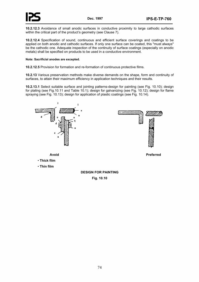
Dec. 1997
IPS-E-TP-760
74
10.2.12.3 Avoidance of small anodic surfaces in conductive proximity to large cathodic surfaces within the critical part of the product’s geometry (see Clause 7).
10.2.12.4 Specification of sound, continuous and efficient surface coverings and coatings to be applied on both anodic and cathodic surfaces. If only one surface can be coated, this "must always" be the cathodic one. Adequate inspection of the continuity of surface coatings (especially on anodic metals) shall be specified on products to be used in a conductive environment.
Note: Sacrificial anodes are excepted.
10.2.12.5 Provision for formation and re-formation of continuous protective films.
10.2.13 Various preservation methods make diverse demands on the shape, form and continuity of surfaces, to attain their maximum efficiency in application techniques and their results.
10.2.13.1 Select suitable surface and jointing patterns-design for painting (see Fig. 10.10); design for plating (see Fig.10.11 and Table 10.1); design for galvanizing (see Fig. 10.12); design for flame spraying (see Fig. 10.13); design for application of plastic coatings (see Fig. 10.14).
Avoid Preferred
• Thick film
• Thin film
DESIGN FOR PAINTING
Fig. 10.10
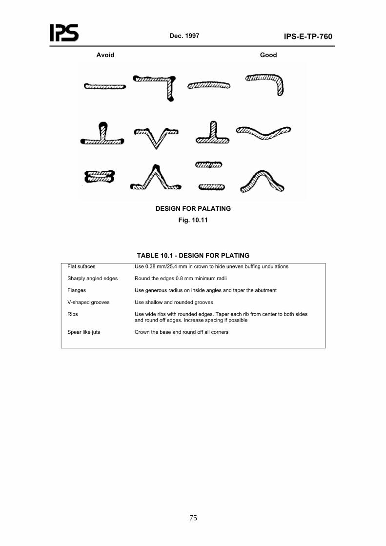
Dec. 1997
IPS-E-TP-760
75
Avoid Good
DESIGN FOR PALATING
Fig. 10.11
TABLE 10.1 - DESIGN FOR PLATING
Flat sufaces Use 0.38 mm/25.4 mm in crown to hide uneven buffing undulations Sharply angled edges Round the edges 0.8 mm minimum radii Flanges Use generous radius on inside angles and taper the abutment V-shaped grooves Use shallow and rounded grooves Ribs Use wide ribs with rounded edges. Taper each rib from center to both sides and round off edges. Increase spacing if possible Spear like juts Crown the base and round off all corners
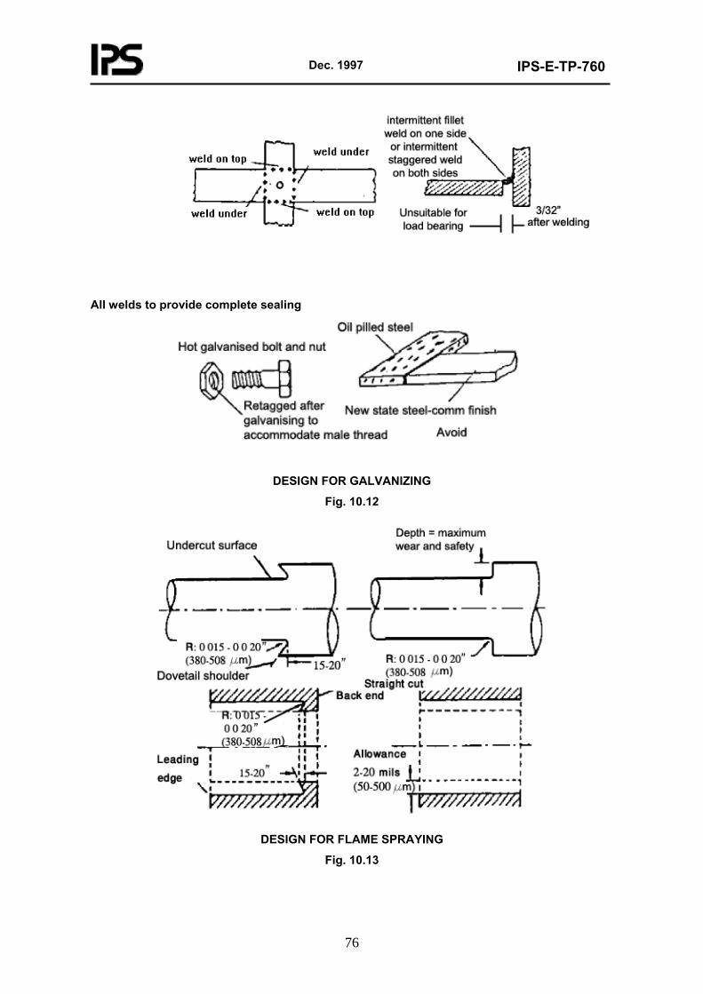
Dec. 1997
IPS-E-TP-760
76
All welds to provide complete sealing
DESIGN FOR GALVANIZING
Fig. 10.12
DESIGN FOR FLAME SPRAYING
Fig. 10.13
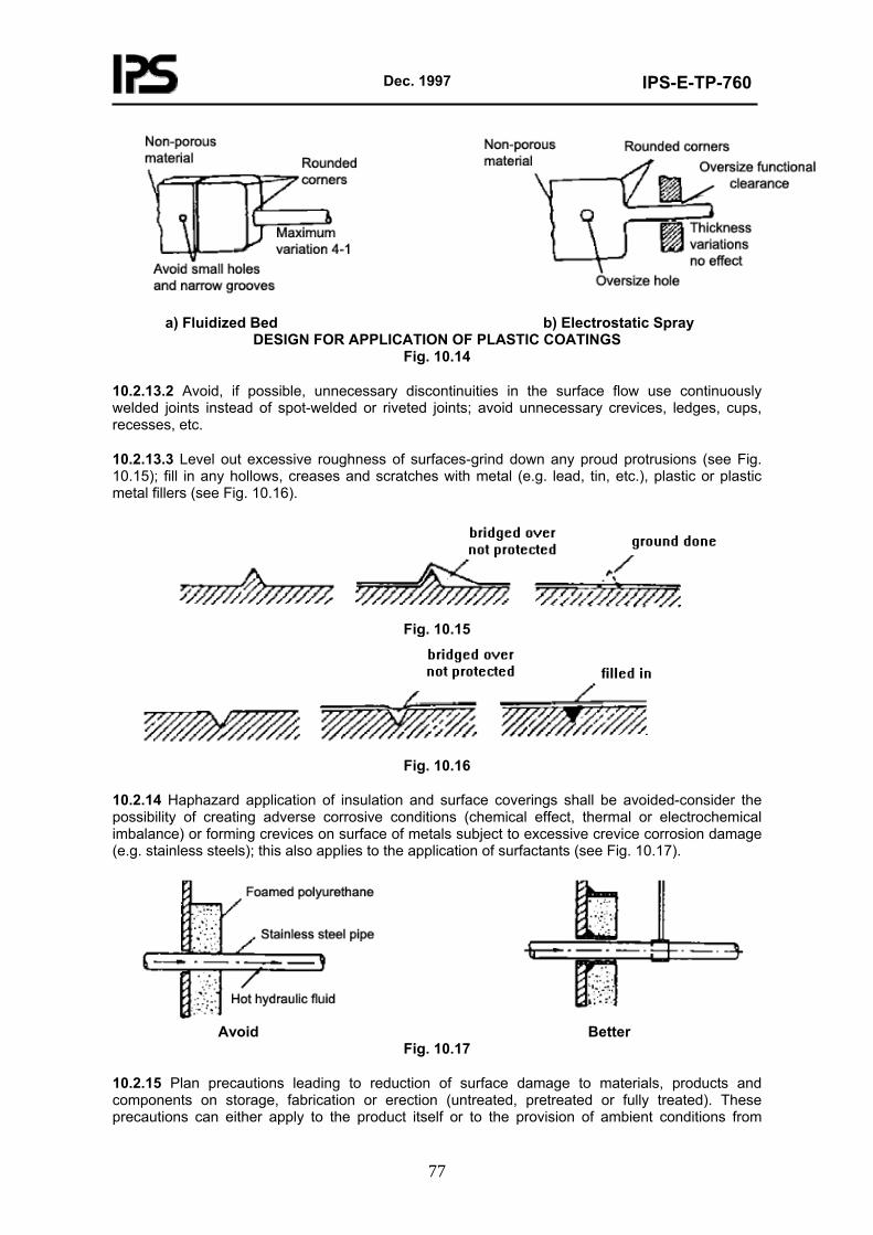
Dec. 1997
IPS-E-TP-760
77
a) Fluidized Bed b) Electrostatic Spray
DESIGN FOR APPLICATION OF PLASTIC COATINGS Fig. 10.14
10.2.13.2 Avoid, if possible, unnecessary discontinuities in the surface flow use continuously welded joints instead of spot-welded or riveted joints; avoid unnecessary crevices, ledges, cups, recesses, etc.
10.2.13.3 Level out excessive roughness of surfaces-grind down any proud protrusions (see Fig. 10.15); fill in any hollows, creases and scratches with metal (e.g. lead, tin, etc.), plastic or plastic metal fillers (see Fig. 10.16).
Fig. 10.15
Fig. 10.16
10.2.14 Haphazard application of insulation and surface coverings shall be avoided-consider the possibility of creating adverse corrosive conditions (chemical effect, thermal or electrochemical imbalance) or forming crevices on surface of metals subject to excessive crevice corrosion damage (e.g. stainless steels); this also applies to the application of surfactants (see Fig. 10.17).
Avoid Better
Fig. 10.17
10.2.15 Plan precautions leading to reduction of surface damage to materials, products and components on storage, fabrication or erection (untreated, pretreated or fully treated). These precautions can either apply to the product itself or to the provision of ambient conditions from

Dec. 1997
IPS-E-TP-760
78
without the boundaries of the component.
10.2.16 Where a surface damage by filiform corrosion on storage can be expected, provide for storing of coated metals in a low humidity environment; coat metals with brittle film; use low permeability permanent or temporary coatings.
10.2.17 Some guides and recommendations on surface are presented in Appendix D.
11. PROTECTION
11.1 General
The function of protection is, to a considerable degree, the upkeep of the optimum anti-corrosion factor built into the particular design itself. Protection on its own, therefore, cannot normally take the sole responsibility for preservation of a utility in a usable state. Both the intrinsic corrosion-control provisions and properties which are kept captive within the material boundaries of the designed structure or equipment, and the corrosion-protection activities which are applied from without, are complementary to each other. The demarcation of their respective boundaries will be largely governed by the rational trade-off of their comparative economic values.
High costing protection may favorably balance the appropriate replacement of more exotic materials or geometric forms with the cheaper ones; it may favourably compensate for reduction in strength, for less frequent maintenance, for better safety of operations, etc. Use of cheap protective measures may often prove false economy.
Protection should be tailored to the particular assembly complex and not to the individual composite parts, subassemblies or units. For optimum protection, consideration should be given to the geometry and location of the utility and its vital parts, ease of application and the effectiveness of the protective measures, these factors being reciprocally adjusted to suit each other. New or revolutionary protective measures and techniques should not be incorporated haphazardly in design-structures and equipment should be designed for their most effective use. The more inaccessible the surfaces, the better should be their protection. Active or passive ecological involvement of protective measures is of prime importance.
Only necessary, safe and economically feasible protection shall be specified, preferably by methods and techniques applied under controlled or automated conditions, thus eliminating or reducing the adverse influence of human variant. The local obtain ability of an efficient and expert labour force, as well as local climatic conditions at the initial production site and at the subsequent ports of call, will have a considerable influence on the selection of protective measures. Where these factors can have a critical effect on the efficiency of protection, preference should be given to those materials, methods and techniques that can give the best results being used at the consequential locality.
Basically, protection comprises those protective measures providing separation of surfaces from environment, those giving cathodic protection or anodic polarization and those which cater for adjustment of environment. These methods can be used individually or in various combinations, the latter affording a greater degree of protection that the sum of individual effects.
11.2 Requirements
11.2.1 Separation of materials from the environment, provided by the following applications:
11.2.1.1 Cladding (see IPS-E-TP-350, Appendix A & B).
11.2.1.2 Painting (see IPS-E-TP-100).
11.2.1.3 Lining with organic and inorganic materials (see IPS-E-TP-350).
11.2.1.4 Coating by non-metallic (see IPS-E-TP-270).
Dec. 1997
IPS-E-TP-760
79
11.2.1.5 Application of metallic coating.
11.2.1.6 Thermal insulation and isolation (see IPS-E-TP-700).
11.2.1.7 Protection by electro chemical cathodic and anodic protection (IPS-E-TP-820).
11.2.1.8 Protection by adjustment of environment (see IPS-C-TP-780).
All the above applications involves primarily a change in surface composition which causes by the addition of different materials (metallic or non-metallic) in the form of an outer skin. Most of these processes involve a dimensional change (except perhaps diffusion coating) and also a weight change.
11.2.2 Protection by separation of materials from the environments
a) Ideal separation of surface requires total exclusion of air and moisture or other corrosive media from the protected surfaces. This is difficult to achieve due to the inherent porosity of various protective materials, due to the limited survival life of these materials and due to these materials being prone to application faults.
b) To provide against the deficiency in effective separation of surfaces, recourse is normally made to multiphase combinations of separation materials applied to surfaces in a form of protective systems, which combine several materials either of the same family or of several complementary categories.
11.2.2.1 Selection of protection system
11.2.2.1.1 Make the basic decision as to the type of separation method to be used with respect to the following considerations:
- Which single or combined method can provide the optimum period of respite from repetitive maintenance and preserve the operational function and anti-corrosion integrity in the given environment.
- Which methods are compatible with the materials to be preserved and, if a combination of separation methods is considered, whether the whole system will be compatible throughout.
- Which methods will suit the considered geometric form initially and at repetitive maintenance; which method will suit requirements of frictional joints.
- What will be the effect of thermal shock, abrasion, impact, overheating and cryogenic temperatures on the selective system.
- What stage of fabrication and assembly may be critical for the optimum application of considered methods to fit well into the production program.
11.2.2.2 Metal coating
11.2.2.2.1 Metal-coating processes can be classified as anodic and cathodic. The anodic ones will protect substrate metal (even when porous or damaged) through their preferential corrosion, whereas the noble metal coatings, which are mainly used for their superior chemical resistance properties, will accelerate the corrosion of metallic substrate in such circumstances (see Clause 7, 8 and Table 11.1).
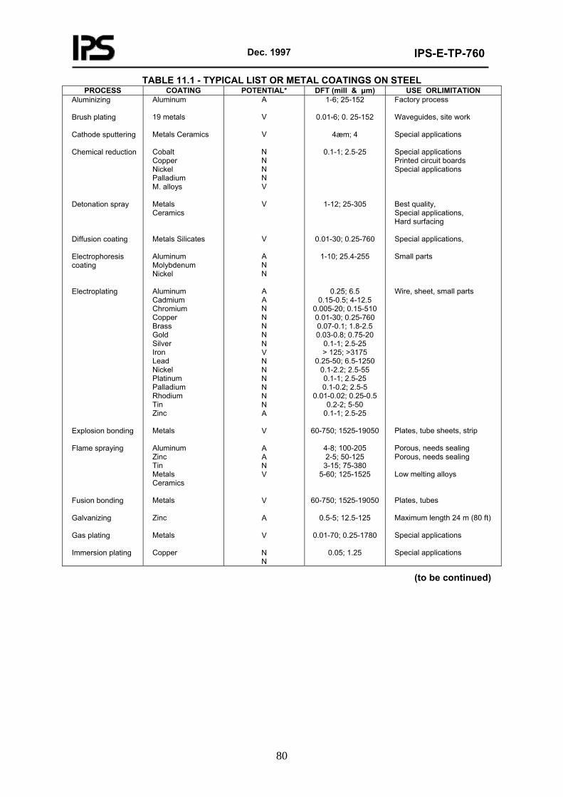
Dec. 1997
IPS-E-TP-760
80
TABLE 11.1 - TYPICAL LIST OR METAL COATINGS ON STEEL PROCESS COATING POTENTIAL* DFT (mill & μm) USE ORLIMITATION
Aluminizing Brush plating Cathode sputtering Chemical reduction Detonation spray Diffusion coating Electrophoresis coating Electroplating Explosion bonding Flame spraying Fusion bonding Galvanizing Gas plating Immersion plating
Aluminum 19 metals Metals Ceramics Cobalt Copper Nickel Palladium M. alloys Metals Ceramics Metals Silicates Aluminum Molybdenum Nickel Aluminum Cadmium Chromium Copper Brass Gold Silver Iron Lead Nickel Platinum Palladium Rhodium Tin Zinc Metals Aluminum Zinc Tin Metals Ceramics Metals Zinc Metals Copper
A
V
V
N N N N V
V
V
A N N
A A N N N N N V N N N N N N A
V
A A N V
V
A
V
N N
1-6; 25-152
0.01-6; 0. 25-152
4æm; 4
0.1-1; 2.5-25
1-12; 25-305
0.01-30; 0.25-760
1-10; 25.4-255
0.25; 6.5 0.15-0.5; 4-12.5
0.005-20; 0.15-510 0.01-30; 0.25-760 0.07-0.1; 1.8-2.5 0.03-0.8; 0.75-20
0.1-1; 2.5-25 > 125; >3175
0.25-50; 6.5-1250 0.1-2.2; 2.5-55 0.1-1; 2.5-25 0.1-0.2; 2.5-5
0.01-0.02; 0.25-0.5 0.2-2; 5-50
0.1-1; 2.5-25
60-750; 1525-19050
4-8; 100-205 2-5; 50-125
3-15; 75-380 5-60; 125-1525
60-750; 1525-19050
0.5-5; 12.5-125
0.01-70; 0.25-1780
0.05; 1.25
Factory process Waveguides, site work Special applications Special applications Printed circuit boards Special applications Best quality, Special applications, Hard surfacing Special applications, Small parts Wire, sheet, small parts Plates, tube sheets, strip Porous, needs sealing Porous, needs sealing Low melting alloys Plates, tubes Maximum length 24 m (80 ft) Special applications Special applications
(to be continued)
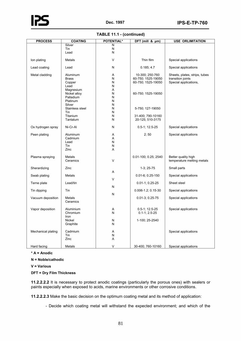
Dec. 1997
IPS-E-TP-760
81
TABLE 11.1 - (continued) PROCESS COATING POTENTIAL* DFT (mill & μm) USE ORLIMITATION
Ion plating Lead coating Metal cladding Ox hydrogen spray Peen plating Plasma spraying Sherardizing Swab plating Terne plate Tin dipping Vacuum deposition Vapor deposition Mechanical plating Hard facing
Silver Tin Lead Metals Lead Aluminum Brass Copper Lead Magnesium Nickel alloy Palladium Platinum Silver Stainless steel Tin Titanium Tantalum Ni-Cr-Al Aluminum Cadmium Lead Tin Zinc Metals Ceramics Zinc Metals Lead/tin Tin Metals Ceramics Aluminium Chromium Iron Nickel Graphite Cadmium Tin Zinc Metals
N N N
V
N
A N N N A N N N N N N N N
N
A A N N A
V
A
V
N
N
A N
N N
A N A
V
Thin film
0.185; 4.7
10-300; 250-760 60-750; 1525-19050 60-750; 1525-19050
60-750; 1525-19050
5-750; 127-19050
31-400; 790-10160 20-125; 510-3175
0.5-1; 12.5-25
2; 50
0.01-100; 0.25; 2540
1-3; 25-75
0.01-6; 0.25-150
0.01-1; 0.25-25
0.006-1.2; 0.15-30
0.01-3; 0.25-75
0.5-1; 12.5-25 0.1-1; 2.5-25
1-100; 25-2540
30-400; 760-10160
Special applications Special applications Sheets, plates, strips, tubes transition joints Special applications, Special applications Special applications Better quality high temperature melting metals Small parts Special applications Sheet steel Special applications Special applications Special applications Special applications Special applications
* A = Anodic
N = Noble/cathodic
V = Various
DFT = Dry Film Thickness
11.2.2.2.2 It is necessary to protect anodic coatings (particularly the porous ones) with sealers or paints especially when exposed to acids, marine environments or other corrosive conditions.
11.2.2.2.3 Make the basic decision on the optimum coating metal and its method of application:
- Decide which coating metal will withstand the expected environment; and which of the
Dec. 1997
IPS-E-TP-760
82
coating metals can be applied to adequate thickness with good coverage.
Note: The danger of micro-cracking of thickly applied chromium, rhodium or hard metals; (corrosion rate of deposited metal from economical and technical point of view).
- Which combination of metallic coating and substrate can provide optimum porosity and galvanic relationship.
- Consider if the coating method change the physical properties of the substrate.
- Will the coating metal allow the desired physical properties (appearance, color, brightness hardness, strength, wear resistance, temperature resistance), electrical conductivity at the allowable cost and is the optimum technology readily available.
11.2.2.2.4 In case of electrode position, consider the followings:
- Which desirable physical, mechanical and chemical properties and what composition of deposited metal are required.
- What thickness of coating is required.
Note: The nature of substrate, nature of coating, environmental conditions and economics.
- What hardness of deposits is required.
- What precautions are necessary to reduce input of high tensile stresses in the deposits.
- What precoating is required to secure effectiveness of deposits.
- Will the substrate be adversely affected by the process solutions (e.g. hydrogen embrittlement).
- Which available method of application is suitable for the designed component (vat process, barrel process, brush plating, chemical reduction, etc.).
- What are the desired main and side effects of deposition (corrosion protection, decorative, specular and heat reflecting finishing, wear resistance, prevention of galling, stopping-off during carburising, electroforming, etc.), and which particular technique can provide the optimal results.
- Which of the practical applications is most suitable for the composite of materials, geometry, surfaces and size of the component.
- What effect will the environmental conditions have on the deposited coatings and, if subject to abrasion, what will be the edge effect of deposited metal on the substrate.
- Which will be the best way to secure non-porosity and uniformity of cathodic/noble coatings.
- Which method of sealing will be compatible with the anodic metals deposits.
11.2.2.2.5 In case of hot-dip metal deposition, consider the followings:
- Will the composite of materials, geometry, surfaces and size of the components suit the available practical application.
- Will the basic metal be adversely affected by the pretreatment process solutions.
- What effect will the environmental conditions have on the deposited metal coating and, if
Dec. 1997
IPS-E-TP-760
83
subject to abrasion, what will be the edge effect of deposited metal on the substrate.
- What thickness or weight of coating is required to provide the optimum protection.
- Will the reduction of coating thickness (by rolling, wiping, centrifuging, etc.) of molten metal be required to secure relevant thickness.
- Will the improvement of properties or appearance of coating by chromatizing, phosphatizing, light rolling or roller levelling be required, and will the removal of palm oil or other post-metallizing treatment be necessary on production.
- Will any change of character of the coating by annealing and conversion, by anodizing or dyeing, be required.
- Will painting of the deposited metal be required.
- Will any preparation or pretreatment of the deposited metal be required prior to further coating.
- Will any joining be possible after metal deposition; which techniques can be used where hot-dip coatings are applied to raw materials prior to fabrication.
11.2.2.2.6 Typical detail appreciation of hot metal spraying (corrosion prevention; sprayed lead for use in atmospheres containing sulphuric acid; tin for food vessels; stabilized stainless steel, nickel and monel for pump rods, impellers, etc., for build-up; hard facing; spray welding; etc.):
- What will be the purpose and use of the metal-sprayed coating.
- Which system of metal spraying will offer the optimum results (molten metal, metal powder, metal wire, electric arc, detonation spray, plasma spray or other).
- Will the bond strength of the flame-spray applied coating exceed the design stress at the interface.
- Will the surface roughness of the substrate be comparable with the particle size of the sprayed metal.
- Will the composite of materials, geometry, surfaces and size of the components suit the available practical application.
- What effect will the environmental conditions have on the deposited metal coating and, if subject to abrasion, what will be the edge effect of the deposited metal on the substrate.
- What thickness of coating is optimal and can be applied to the substrate without obvious shear stress between dissimilar metals (shrinkage) which may arise, especially in environmental conditions of fluctuating temperatures, sustained vibration, etc.
- Will overall uniformity of thickness and minimum porosity be obtained?
- What hardness of the coating is required?
- What sealing will be necessary to counteract the porosity of the sprayed metals?
11.2.2.2.7 For critical applications, and since thermal-sprayed coatings are not homogeneous materials, it is further advisable to consider:
- Behavior of melted particles on passage through the flame and the change in composition involved, pick-up of contaminants, embrittlement of layers and its influence on thermal expansion, thermal conductivity and strength of the coating.
Dec. 1997
IPS-E-TP-760
84
- Some metals show higher strength on the plane parallel to the surface than the one perpendicular to it.
- Porosity influences the strength of ductile and brittle coatings, and therefore the pore size, shape and volume of porosity shall be evaluated.
- Porosity is influenced by variables such as torch to substrate distance, spray environment, substrate temperature and spray process.
- Pore volume decreases the heat conductivity of the coating.
- The bond strength must exceed the design stress at the interface and this is relative to the true surface area, its roughness and the thickness of the coating.
11.2.2.2.8 In case of diffusion coatings consider the followings:
- Will the composite of materials, geometry, surfaces and size of components suit the available practical application.
- Will the basic metal be adversely affected by the pretreatment process solutions and by the heat of compression of the diffusion process.
- What effect will the environmental conditions have on the diffusion layer and what will be the edge effect when damage occurs.
- Will the process secure the overall non-porosity of the coating.
- Normalizing, air-hardening and other pretreatments, air or gas welding, brazing and silver soldering, etc. aversely affect the diffusion coating.
11.2.2.3 Coating system (paints) (see IPS-E-TP-100):
11.2.2.3.1 The complete coating system is a complex multi-purpose finish, performing protective, sealing and decorative functions (it may also provide lubrication, conductivity, etc.). The system is the basic engineering unit of surface separation rendered wholly or partially by surface coatings or linings. The complete system comprises:
- Preparation of surface to provide optimum interface.
- Application of the required film thickness of the anti-corrosive medium (metallic or non-metallic), the thickness depending upon the service requirements of the coating system.
- Application of the required thickness of sealing and/or decorative medium (sealer) to secure sufficient impermeability against the environment and thus to extend the functional readiness of the anti-corrosive medium.
- Application of special-purpose coatings (anti-condensation, noise damping, etc.).
11.2.2.3.2 The most important parts of the coating system are the preparation of surface (see IPS-C-TP-101) and the selection and application of anti-corrosive medium (various anodic metallic coatings, prefabrication primers, organic or inorganic corrosion-inhibiting primers, conversion coatings, anodizing). Undercoats are only for improvement of appearance.
11.2.2.3.3 Prefabrication primers are an important part of the whole preservation system. Their integrity shall therefore be preserved throughout the process of manufacture, and every economically sound remedial action taken to repair any damage as soon as possible whilst fabrication proceeds and definitely prior to the application of the next coating; on area shall remain untreated and open to corrosion for extended periods. All necessary activities shall be included in the production planning.
Dec. 1997
IPS-E-TP-760
85
11.2.2.3.4 Prefabrication primers shall satisfy following requirements:
- Cover adequately the contours of the surface.
- Allow an easy application by brush, roller, spray (all types including electrostatic spray) or by any other method available, required or suitable.
- Secure a fast drying time-not more than 5 min for spray application and 20-30 min for brush or roller applications.
- Have a reasonable pot life.
- Supply a good temporary protection by a thin film both before and after fabrication, until such time as the full paint system can be applied.
- Provide good, if possible permanent, base for widest range of subsequently applied coatings.
Note: Solvent resistance.
- Be free of toxic fumes on cutting and welding.
- Will not interfere adversely with flame cutting and welding operations or the quality of the weld outside of established parameters-will also provide only for a minimum back burn without major damage.
- Will withstand cold working of the metal without flaking.
- Be electrically conductive where earthing in fabricated structure is required.
- Possess a good resistance to abrasion and good adhesion to withstand fabrication, transportation and erection.
- Be reliable when used under cathodic protection.
- Be eventually tin table in various colors for marking different grades of basic construction steel, for marking distinctive sections of structures, etc.
11.2.2.3.5 There is a large range of primers to choose from, differing in their purpose and quality. The differences, however, are not confined only to the variety of utility and quality within each generic group but also to the design of the coating regarding its method of application and the thickness of the applied film. Where the coating is to be applied to a relatively smooth surface, with no sharp peaks and for a limited or temporal utility, then a thin film (e.g. prefabrication primer only, etc.) may suffice. Where the texture of the surface is rather more pronounced, where the corrosive conditions are more aggressive and where extended protection is needed, then a thicker film is required; in this case the original pretreatment shall be extended by addition of one or several further coatings of primer to suit. Two-step application procedures shall be used. Where the texture is even coarser, as on corroded steel, then a very thick film is required. In this case, high build primers can be used, the number of coats varying with the expected life and environmental conditions. (see Table 1 of IPS-E-TP-100).
11.2.2.3.6 A sealer primarily means any coating or lining which is applied on top of anti-corrosive compositions for the purpose of extending their utility in an efficient state for an economic period. The general requirements of a good sealer are as follows:
- Good adhesion to the anti-corrosive composition.
Dec. 1997
IPS-E-TP-760
86
Note: The use of barrier (tie) coats for improvement of adhesion.
- Low permeability to water or other corrosive media.
- High film thickness.
- Good chemical resistance.
- Optimal resistance to abrasion.
- Good weather resistance, including resistance to ultraviolet light.
11.2.2.3.7 Where protection is required against atmospheric corrosion only (e.g. under rural conditions), it may not be necessary to use sealer provided an adequate film thickness of sacrificial metal contained, for example, in metallic coating or inorganic zinc coating, is applied. Otherwise an application of sealer is a necessity, observing that it is in the interests of the proprietor of a utility to avoid repetition of expensive overall preparation of surface. Sealer extends the effectiveness of anti-corrosive composition and the anti-corrosive composition prevents the onset of corrosion which had penetrated through damaged and porous sealer. Both are complementary to each other.
11.2.2.3.8 Seventy-five percent of the success of protection depends on adequate surface preparation and reliable application. The use of technically skilled industrial and approved applicators is recommended. Engineering planning, accurate specification and complete scheduling of the protection by protective coatings is a necessity, (see IPS-C-TP-102).
11.2.2.3.9 Protective coatings shall only be used if it is more economical than use of corrosion-resistant metals and other materials.
11.2.2.3.10 Care shall be taken to ensure that all materials are stored, handled and maintained to avoid physical damage, contamination and deterioration of the protective coatings, and the requisite precautions shall be planned.
11.2.2.3.11 Protection by separation of surface from environment by protective coating shall be evaluated together with relevant parts of Sections on 7, "Compatibility" 9, "Mechanics" and 10, "Surface". Further the problems and limitations of the applicator, climatic and working conditions, properties of materials in relation to procedures and schedules shall be reviewed; application methods to suit the geometry chosen; systems which permit maximum application of money saving practices, use of minimum number of different materials and least number of colors selected; maintenance practice anticipated.
11.2.2.3.12 Typical detail appreciation of proprietary prefabrication primers (further to IPS-E-TP-100) is as follows:
- Will there be suitable and effective facilities for prefabrication priming available; can the prefabrication-primed metal be supplied ex stock.
- Will the substrate metal be suitable for prefabrication priming (type and thickness).
- Will the handling, storing and fabrication facilities and program be attuned to the proprietary prefabrication primer?
- What is the workmen’s (trade unions) attitude towards the working of prefabrication primed metals, especially welding?
- Will the removal of primer prior to flame cutting or welding be necessary (critically loaded structures), or can arrangements be made to mask the critical welding surfaces prior to priming.
- Will it be necessary to remove the proprietary primer overall or partially to further coating?
Dec. 1997
IPS-E-TP-760
87
- What will be the effect of weathering (in stock and in work) on prefabrication primed metal and what precautions will be necessary prior to application of further coatings.
11.2.2.3.13 Suitably precoated metals (fabrication process) are preferred to complete or partial post-fabrication treatment where the degree of required protection, the construction and the joining will permit.
11.2.2.3.14 Typical detail appreciation of plastic coatings is as follows:
Note: General appreciation of plastic coatings will be similar to the appreciation of paint coatings.
- Will the plastic coating lend itself to application by available facilities.
- Will the process be rapid and economic enough.
- Will the plastic coating withstand atmospheric weathering conditions.
- Will the plastic coating be tough enough to endure the abrasion and impact of handling, loading and unloading of storage and transport facilities, and stringing equipment.
- Will the plastic coating have sufficient flexibility to withstand the maximum bends utilized at temperatures from -6.7°C to 60°C (20°F to 140°F).
- Will it not melt or burn back within 1.2 cm (½ in) of the weld and be compatible with a joint system subsequently applied to protect the weld area.
- Will it resist the impact of rocks and soil during backfill operation; also, will it resist the wear and tear of fitting and normal operation.
- Will it not crack or disband during hydrostatic and other testing.
- Will it not soften at temperatures below 93°C (200°F) when used on hot line service.
- Will it resist penetration of subsurface waters or liquid contents?
- Will it resist the chemical attack from outside (e.g. natural soil chemicals, fertilisers) or inside.
- Will it not be attacked by bacteria and fungus in the soil?
- Will it resist the solvent action of products in permanent contact or occasional contact in the event of overflow, spillage or breakage (e.g. aviation gasoline, jet fuel, crude oil, etc.).
- Will it possess the adhesive forces and chemical inertness which will resist, within an economical lifetime, the effects of cathodic protection systems in soils or sea water of low resistivity?
11.2.3 Protection by electrochemical cathodic and anodic (see IPS-E-TP-820)
11.2.3.1 The designer shall decide initially whether the polarization of materials in conductive media shall be secured by:
- Cathodic protection-ships’ hulls and appendages, cargo and ballast compartments, bilges, sea inlets and discharges, off-shore structures, jetties and navigational aids, off-shore pipelines, harbor structures, heat exchangers, box coolers, large seawater storage tanks, buried pipelines, well casings and gathering lines, public utilities, lines and cables, buried feet of overhead power pylons and metallic telephone posts, industrial storage tanks, gas holders, bottle washing machines and other industrial plant, reinforcing rods and wires in prestressed concrete and other structures or equipment immersed in aqueous solutions of
Dec. 1997
IPS-E-TP-760
88
electrolyte (pure water, river water, potable water, sea water, wet soils and weak acids) and in weak to medium corrosive environments where proportionally higher consumption of protective currents is allowed.
- Anodic polarization of active/passive metals-alloys of nickel, iron, chromium, titanium and stainless steel in weak to extremely corrosive environments, where economy in consumption of protective currents is required.
- Coating with anodic metals (zinc, aluminum, cadmium), which may be appreciated either as a part of surface separation or a part of cathodic protection.
11.2.3.2 When the initial decision to use cathodic protection has been made it must be decided upon whether to use impressed currents or sacrificial anodes by:
- Size and geometry of the project (impressed currents method is usually used for large projects).
- Availability of the power supply.
- Possibility of the interface problems.
- Necessity for safety from spark hazards and accumulation of hydrogen in enclosed spaces.
- Replace ability of sacrificial anodes.
- Expected economic life of the system.
11.2.3.3 Typical basic appreciation of cathodic protection by sacrificial anodes is as follows:
- Estimate of total current requirements (current densities allowed, spare capacity, allowance for protective coatings and linings, assessment of environmental media).
- Resistivity of water, soil or other electrolyte solution.
- Requirements for insulating flanges and bonding to foreign structures and assessment of extra current allowances.
- Selection of suitable anode metal (zinc, magnesium, aluminum, iron, mild steel or other metals anodic to the protected structures or equipment) and its alloying composition.
- Requirements for introduction of current control to limit output within the optimum parameters.
- Selection of the size of anodes to provide optimum life.
- Selection of the suitable shape of anodes to secure optimum spread.
- Determination of the total number of anodes required.
- Anode spacing to give uniform current distribution.
- Selection of test-point localities.
- Attachment of anodes.
Note: Sacrificial anodes shall be conductively attached to the protected metal but their sacrificial mass should preferably be separated from the protected surfaces.
Dec. 1997
IPS-E-TP-760
89
11.2.3.4 Typical basic appreciation of cathodic protection by impressed current/cathodic control; are as follows:
- Estimate of total current requirements.
- Resistivity of water, soil or electrolyte solutions.
- Requirements for insulating flanges and bonding to foreign structures and equipment and assessment of extra current allowances.
- Selection of suitable groundbed locations (in low resistivity soils or media, reasonably near power supply, at points where there are no interference problems, where beds and cables are reasonably secure from interference or disturbance).
- Decision on the type of anodes and the design of their attachment.
- Decision on whether the anodes (if elongated ones selected) shall be installed vertically or horizontally.
- Decision on the voltage to be used.
- Determination of the optimum anode material.
- Optimum number and size of the anodes.
- Decision on anode spacing.
- Type and location of reference electrodes.
- Requirements and design of grounding of propeller shaft, rubber and other attached substructures and equipment within the protected complex-materials and systems.
- Location of controllers, power supply and transmission (cabling and installation).
- Potential hazards of marine and surface traffic.
- Wave action and soil instability.
- Bottom involvement.
- Weed fouling and microbiological effect.
- Malicious damage.
11.2.3.5 Where cathodic protection is to be used the alkali resistance of the protective paint coatings shall be evaluated.
11.2.3.6 Where possible, cathodically protected surfaces shall be preserved by suitable surface coatings or linings.
11.2.3.7 All precautions shall be taken to prevent hydrogen embrittlement of high strength metals arising from their cathodic protection.
11.2.3.8 Detail design of cathodic protection systems is a highly specialised field of expertise and shall be left primarily to a corrosion specialist. However, it will be the designer’s task to accommodate, eventually, the diagrammatic detail design rendered by the corrosion specialist in the functional design of the utility to their mutual satisfaction.
11.2.3.9 Use of zinc-rich primers on cathodically protected structures or equipment in conductive environment is not generally recommended.
Dec. 1997
IPS-E-TP-760
90
11.2.3.10 Typical basic appreciation of anodic polarization by impressed currents/anodic control are as follows (further to IPS-E-TP-820):
- Estimate of total current requirements.
- Is the used chemical/metal system suitable for anodic polarization (e.g. oleum and carbon steel, cold concentrated sulphuric acid and carbon steel, hot concentrated sulphuric acid and stainless steel, dilute sulphuric acid and stainless steel, etc.).
- Conductivity of liquid, its temperature, pH, pressure and velocity.
- Minimum, normal and maximum concentration of the liquid.
- Is any substance present which might coat, abrade or coagulate.
- Decision on the type of the cathodes and design of their attachment.
- Decision on the voltage to be used.
- Selection of the optimum cathode material.
- Optimum number, size and spacing of cathodes.
- Type and location of reference electrodes.
- Location of controllers, power supply and transmission.
- Potential fouling of cathodes and reference electrodes.
11.2.4 Protection by adjustment of environment (see also IPS-E-TP-780)
11.2.4.1 Reduction of corrosion by a change of environment is to be considered, provided the design is suitable and this can be achieved without excessive cost by any one, or several, of the following methods:
- Lowering the corrosiveness of the atmosphere or other corrosive media by ventilation, dehumidification, air conditioning, reduction of acid strength, sacrificing chemical efficiency for the sake of lower corrosion costs, continuous venting of steam from the unit, reduction of concentration of CO2 and oxygen in condensate, etc.
- Adjusting the thermal efficiency of the components by raising or lowering the temperature by reduction of thermal efficiency of preheaters and boilers, by making heat exchangers co-current instead of counter-current, by reduction of peak metal temperature, etc.
- Using the inhibitors in critical media, e.g. fuels, process liquids, cooling waters, paints, elastomers, etc.
11.2.4.2 Typical basic appreciation of ventilation, dehumidification and air conditioning for change of environment are as follows:
- Requirements for habitability.
- Adjustments of environment to improve protection through control of corrosiveness.
- Corrosion rating of particular design complex.
11.2.4.3 Desiccating agents used in corrosion prevention must be cheap, easy to handle and non-corrosive. An easy access for inspection and replacement must be provided and eventually a provision for regeneration in situ shall be made.
11.2.4.4 Typical basic appreciation of inhibitors for the purpose of change of environment are as follows (see IPS-E-TP-780):
- What is the effect of inhibitor concentration on corrosion rate?
- Minimum concentration needed.
- Tendency to favor pitting-effects at water line.
- Relation to surface area of metal-initial consumption (in coating surface, in reacting with existing corrosion scale).
- Effectiveness as a function of time.
Dec. 1997
IPS-E-TP-760
91
- Tendency to be consumed by reaction with ingredients of corrosive medium.
- Effectiveness under varied conditions that may be found in plant different temperatures, concentrations of corrosive, velocities, aeration, etc.).
- Effectiveness on metal already corroded.
- Can the cost of maintaining a sufficient quantity of inhibitor in the system, and the cost of testing that this quantity is being maintained at an appropriate level, be kept within reasonable economic boundaries.
- Can the inhibitor contaminate the product/contents.
- Can the inhibited fluid present an effluent problem.
- Can the inhibitor loosen corrosion deposits and thus cause blockages.
- Can the inhibitor precipitate on stream and can the sludge or scale thus formed be acceptable.
- Can the organic inhibitor coat heavily the surfaces to the important and considerable detriment of efficiency of the heat transfer and filtration or may it give undesirable emulsification, iron exchanger, etc.
- What effect will it have on other metals that may be present effect on bimetallic couples.
- Can the inhibitor cause foaming and thus impair the operation.
- What are the hazards in handling toxicity.
- What would be the cost and effect of the fall in the inhibitor concentration?
11.2.4.5 The combined effect of inhibitors and cathodic protection is far greater than the individual effect of each method separately.
11.2.4.6 Avoid packaging materials containing soluble salts or acids in significant quantities or emitting corrosive vapors. Prevent entrapment of gaseous contaminants carried by air between the metallic components and the packaging materials.
11.2.5 Some guides and recommendations on protection are presented in Appendix E.
12. MAINTAINABILITY
12.1 General
It would be a truly ideal achievement to provide, in design, for an a absolute functional reliability of a utility during its full operational life-from its conception to the termination of its usefulness. This, however, will be only very seldom possible in practice and the designed structure or equipment may fail as a result of random catastrophic failures of individual parts or by progressive degradation and deterioration of performance. Corrosion-control assessment should take account both of catastrophic and degradation failures with the understanding that each can be caused by a conglomerate of both mechanical and corrosion factors.
The designer can expect that during the utility’s operational life its failures, including the failures of intrinsic corrosion control, will proceed in three stages. In the first phase, representing the debugging period, the failure rate will rapidly decrease from an initial peak, due to replacement of parts and correction of design and practical manufacturing and preservation errors.
In the second phase, a constant failure rate of lower power can be expected and this can further be
Dec. 1997
IPS-E-TP-760
92
reduced to the lowest possible frequency and potential by the diligent effort of designers and corrosion specialist. In this way the period of the utility’s useful can be extended to the most economic length of time, with the help of operational maintenance, when necessary.
In the third, or wear-out phase, the incidence of failures will again rise through a combination of catastrophic and deterioration failures. It is again in the hands of the mentioned group of specialists to postpone this period to the ultimate end of the utility’s useful life.
12.2 Requirements
When failures occur, the cost of major repairs, the danger of pollution of contents by corrosion products, the loss of productivity, the danger of destruction of a utility and of human life shall in most cases, enforce some sort of operational or preventive maintenance. As long as the equipment has to be maintained, its maintainability must be ensured. Followings are the major tasks to be considered with respect to maintainability.
12.2.1 All corrosion-control precautions included in design shall be ’inspect able’. Their temporal state and efficiency shall be open to observation under the conditions given by the selected geometry of the utility, its location and its arrangement and this shall be possible in the ambient environment of production, operation or maintenance and with reasonable ease.
12.2.2 All specified corrosion-control precautions shall be ’repeatable and repairable’ with reasonable ease in the given position and environment, as far as possible.
12.2.3 Preference of replacing the whole utility (or its individual parts) instead of repetitive maintenance shall be assessed on economic and operational conditions of the utility.
12.2.4 Fundamental changes of the design concept may be necessary to avoid major impediments in maintenance, especially on complex structures and equipment in a corrosion-prone environment.
12.2.5 Anti-corrosion maintenance shall either require the shortest possible length of time to be executed or it shall be as widely spaced as possible (e.g. in the case of structures and equipment or parts located of necessity in inaccessible positions). Design shall be based on optimal length of corrosion prevention.
12.2.6 The anti-corrosion maintenance shall lend itself to a planned maintenance program, which shall be implemented with the least interference to the operation or use of the utility and be at the same time compatible with the corrosion incidence.
12.2.7 Periodicity of maintenance shall suit the operational cycles to cause the least possible inconvenience all round.
12.2.8 All precautions shall be taken in design to reduce the cost and degree of difficulty of subsequent maintenance, including dismantling and reassembling of structures and equipment, cleaning and preparation of surfaces in situ, preservation, etc., to a minimum. All such operations shall be made easy and foolproof.
12.2.9 Due consideration to the safety of the maintenance personnel shall be given (e.g. easy and adequate access with the tools, provision of maintenance platforms, temporary ventilation, lighting, etc.).
12.2.10 Fast corroding and critical parts shall not be located in inaccessible positions within a utility, which would involve maintenance personnel in major dismantling operations. Such parts or units shall be easily removable. Parts requiring difficult anti-corrosion maintenance shall not be positioned in dark places.
12.2.11 Materials and protective systems shall be selected with an inherent economic length of resistance to corrosion.
Dec. 1997
IPS-E-TP-760
93
12.2.12 Anti-corrosion maintenance shall be adjusted to suit problems arising from engineering maintenance procedures (e.g. physical damage, spillage of chemicals, etc.).
12.2.13 Accessibility for inspection shall be reconciled with the selected inspection and destructive or non-destructive testing procedures (e.g. X-rays, ultrasonic, visual, probes, instruments, etc.).
12.2.14 Probable expertise and availability of future maintenance personnel may govern selected maintenance requirements.
12.2.15 Use of modular assemblies tailored to the requirements of corrosion control is recommended.
12.2.16 Some guide and recommendations an maintainability are presented in Appendix F.
13. ECONOMICS
13.1 General
Corrosion, as such, is basically an economic problem associated closely with the loss of capital assets and business profits; corrosion control shall provide the most advantageous course of obviating such losses in the first case, whilst not neglecting the most important implications of safety, health, pollution of environment and products, which have a very close affinity with corrosion damage.
The corrosion specialist and the involved designer shall primarily be concerned with achieving optimum allowable economy in each specific case on their drawing board. Current corrosion-control technology is usually able to offer a selection of acceptable solutions to any particular corrosion problems, although it may be difficult to select the best one without a common denominator. The selection of optimum solution cannot thus be based only on the understanding and knowledge of corrosion technology but the pertinent cost value must also be known. Selecting an ultimate in corrosion technology may sometimes prove the least profitable venture and a losing proposition.
Whilst basing his decision on a realistic appraisal of economy a designer can distinguish which combination of material, method, technique and system from the selective range is the best proposition, by trying to answer following questions:
a) Would more expenditure on corrosion control be economically advantageous?
b) Could greater savings be obtained, at the present level of expenditure, by better application of the money spent?
c) Does it pay to accept a given degree of corrosion rather than to spend more money on controlling it?
d) What premium on expenditure will satisfy the public requirements for safety and healthy environments?
The fullest investigation is necessary to answer these questions.
This Section provides a basis guidance to the art of economic evaluation of the particulate factors of corrosion-control appreciation and compromising the complete integrated corrosion control of the whole project.
13.2 Requirements
13.2.1 Where possible, and subject to availability at the time of analysis, all elements of costs shall be included in the economic evaluation of corrosion control in design. These elements are as follows:
Dec. 1997
IPS-E-TP-760
94
13.2.1.1 Direct costs for:
- Direct labour (original, service, replacement; operating time for tank washing and gas freeing, fresh water rinse);
- Direct materials (original, service, replacement);
- Over-design (part);
- Subcontracts (including ex works treatments);
- Deterioration and preventive measures;
- Travel and transport (e.g. dock fees. etc.);
- Contract labour;
- Consultants’ services;
- Sampling and testing including NDT (Net Data Throughput) procedures;
- Pilot projects.
13.2.1.2 Indirect costs
- Indirect labour;
- Indirect materials and supplies (receiving, inspection, storage, handling, etc.);
- Over-design (part);
- Delays;
- Safety and insurance;
- Downtime (shut down);
- Efficiency losses;
- Product losses;
- Contamination of environment;
- Contamination and decontamination of product;
- Freight and cargo loss (due to the coating and rust scale formation);
- Freight and cargo loss during critical period;
- Loss or gain of turnaround time (improvement of drainage in rustless tanks and vice versa);
- Cost of potential catastrophic failure;
- Cost of potential fire;
- Repair of damage caused by corrosion to own and other properties.
Dec. 1997
IPS-E-TP-760
95
13.2.1.3 Overheads (prorated)
- General and administrative (marketing, executive salaries, corporate expenses, etc.);
- Rental of machinery and equipment;
- Depreciation of machinery, equipment and facilities;
- Fringe benefits, sickness, vacation and holidays;
- Insurance;
- Taxes, less development subsidies;
- Heat and light;
- Utilities;
- Plant operating expenses;
- Repairs and maintenance;
- Research and development;
- Laboratory supplies and stationery.
13.2.1.4 Profit or loss
- Cost of borrowing (interest on loans);
- Cost of capital (return on investment);
- Recovery profits and salvage values;
- Inflation trends.
13.2.2 Good and comprehensive specifications are essential to any accurate economic evaluation of corrosion-control precautions. The estimator needs to know exactly what is needed from the producer/erector/assembler and applicator in order to intelligently evaluate the whole job.
13.2.3 Where exact instructions or specifications are not available, the contractor is going to bid and con sequently furnish that product which is most economical. For a meaningful economic evaluation, the following information must be known:
13.2.3.1 Accurate description of the job; what is to be done and what is not to be done; where the job is to be done and how long.
13.2.3.2 Avoidance of general terms of instructions; instructions to be referenced to standards or spelled out in exact technical terms and comprehensively described.
13.2.3.3 Production and application methods formulated and accurately described; machinery and tools described.
13.2.3.4 Corrosion-control systems exactly specified and conditions of their application stated.
13.2.3.5 Safety requirements and auxiliary equipment described.
13.2.3.6 Storage and materials or product movements, workmanship, weather limitations, flow of productions and assembly, decontamination and ventilation procedures, specific instruments by
Dec. 1997
IPS-E-TP-760
96
trade name and number, hiring charges, inspection requirements, etc., comprehensively described.
13.2.4 Parallel to management’s anxiety at the alarming increase of the cost of construction and investment, the main concern of the economies of corrosion control in design lies in the reduction of expenditure and the increase of profits. Economics being a social science and engineering an applied science, the economic evaluation of corrosion-control contents of design serves to bridge the gap between these two human activities, to interpret the intention of relevant engineering endeavor to the management in the meaningful language of money and to temper the flight of the engineering invention by the stark realities of commerce.
13.2.5 Any unproductive deterioration of materials and facilities by corrosion damage shall be recognized as an important loss of material and human resources, which could be otherwise used for a productive purpose.
13.2.6 The degree of corrosion control applied in the designed product is a matter of sound economics. The designer’s job is to achieve the desired balance of effect for a minimum in capital outlay, maintenance and replacement costs, cost of inconvenience and social depredations or the potential wastage of human life. However, more expensive materials or products than absolutely necessary shall not be chosen, unless it is more economical in the long run, necessary for safety or for other important reasons.
13.2.7 Sometimes a timely replacement of deteriorated components may be more economical than such precautions, which require high initial expenditure or an extended maintenance. The cost of remedial maintenance or the cost of making do with the deteriorating structures and equipment shall be known. Corroding components can then be replaced at a later date with new, used or improved materials or components; the design shall be adjusted accordingly.
13.2.8 To increase the utility of structures and equipment subject to corrosion, the designer may look at the long-term factors influencing their degree of utilization. These factors are:
- Amount of capital equipment per user.
- Level of technology applied to the work.
- Quality of labour force, depending on the education, training and motivation.
- Skill, drive and intent of the executive branch of the involved organization.
13.2.9 The groundwork of correct economic evaluation and decision-making in corrosion control rests with comprehensive recording and periodical evaluation of the cost and effectiveness of materials (including their interrelation), systems, technologies and personnel. This preferably segregated for each given component, system, unit or grouping. The whole of a given project shall be covered.
13.2.10 Good records are better than a good memory in establishing the onset of the corrosion problem, the frequency of its occurrence and immediate past cost. Decision shall be reached on all information available and recorded, using the best estimates of cost, life and other germane factors that can be obtained at the time.
13.2.11 Effects of previous corrosion-control precautions or procedures shall be classified as to whether these are constant problems or seasonal, whether they are progressive or static.
13.2.12 Historically documented cases of corrosion behavior of materials, structures, plant, equipment and the methods of corrosion control shall be considered with caution; the response of materials, designs and preservation systems may vary considerably in the vast variety of corrosive conditions in existence.
13.2.13 Where a considerable number of items of corrosion control import (e.g. corrosion failures) of a comparatively restricted and repetitive nature can be expected, electronic data processing and
Dec. 1997
IPS-E-TP-760
97
periodic analytical summaries may be very useful for the process of economic evaluation.
13.2.14 Corrosion failures, especially those associated with stress corrosion cracking, fatigue corrosion and similar, are often, by mistake, classified under the costs of mechanical breakdowns.
13.2.15 In any given project, life expectancy, frequency of recurrence, etc., shall be estimated and evaluated.
13.2.16 All estimates of life expectancy may be only an educated guess, based on a thorough study of a range of possibilities obtained by the averaging of statistical data; these do not always agree with actual experience.
13.2.17 Service life of existing materials, even when correlated with recorded corrosion test data, shall be weighed in the light of the costs (first cost, average yearly expense of replacement, average yearly expense of routine maintenance, average yearly expense of operating costs, average yearly expense of down-time, etc.).
13.2.18 Information on the service life pattern of selective materials is based on the following data.
- Information on wastage limits in a given environment and in a particular location, based on the mean corrosion rate plus the standard or observed deviation.
- Information on the critical thickness or strength of materials to secure the integrity of the appreciated structure or equipment.
- Information on the expected materials renewal periods in the particular locations for various structural members or groupings.
- Information on the distribution of materials amongst various structural members, or groupings by logical divisions in corrosion patterns.
- Information on miscellaneous material repairs of structures and groupings.
- Information on possible benefits of corrosion.
13.2.19 Both the external and internal corrosions shall be included in the estimation of the service life in the progressive corrosion-rate figures.
13.2.20 For comparative evaluation of various technological solutions of the given corrosion problem the results of individual calculations shall be converted to a common denominator, e.g. cost per day, cost per year, cost per life or to any other suitable financial base.
13.2.21 Select the design, system or method which will make the greatest reduction in overall operating cost and provide the prerequisite safety accounts for the first application of corrosion economics in corrosion-safe design.
13.2.22 For estimation of corrosion-control economy the estimator shall make every effort to project the immediate past experience into the future with a help of projection graphs, where possible.
13.2.23 The annual corrosion rate of steel has little or no bearing on paint selection; the main concern is with the service life of the paint system in destructive exposures and a possible occurrence of rust-creep. Neither does it affect the selection of surface preparation nor the selection of a cathodic protection system.
13.2.24 The ultimate paint system shall be restricted for economic reasons to the aggressive areas and the less expensive systems used for less destructive exposures.
13.2.25 In the economic evaluation of painting preservation the cost of materials is not indicative on its own-the cost of labour (approximately 80%), auxiliary provisions (scaffolding, plant, ventilation,
Dec. 1997
IPS-E-TP-760
98
drying, lighting and cleaning), accommodation and transport of personnel must be included.
13.2.26 Surface estimating aids presented by many paint suppliers are not valid for economic evaluation of paint systems-the true surface areas form the base for estimates (texture, undulation, fasteners, flanges, etc.).
13.2.27 For appropriate evaluation of a particular paint system the most important factor is its maintenance cost per square meter per year, and this consideration shall be coupled with the serviceability of the paint system in variable conditions (e.g. change of cargo in a ship or similar).
13.3 Methods of Appraisal
13.3.1 Having decided upon the integrated technical concept of corrosion control the corrosion specialist must be prepared to obtain optimum economy from his conclusions and to present his supporting arguments to his principals in terms that are readily comprehensible. He has thus to secure their backing not only for the preferred corrosion control that is technically sound but also offers the greatest economic advantage and increases their profits. Basically he is faced with three possible types of decision as follows:
Type 1: Selection of optimum corrosion control for a brand new process or untested project. No money value can be consigned to corrosion control.
Type 2: Clear-cut decision; concept A costs less money than concept B and has the same life expectancy or costs the same and has a longer life-normally both lives being shorter than one year.
Type 3: Comparison between specific concepts of different costs and different anticipated lives, where not only the financial cost of the new project but also the subsequent upkeep of its utility during its economic life has to be compared.
13.3.2 The systematic analysis of corrosion control in design is primarily concerned with the last type of financial comparison. There are several different techniques of calculating the economic appraisal of corrosion control at hand as follows:
- Comparison of money outflow for short-time projects.
- Life versus cost comparison-value of money and possible cost of production losses not being considered.
- Pay-out period comparison of the cost of an item of corrosion control, divided by the income or savings it produces per year-taxes and time value of money not being considered.
- Return on investment comparison, which is reciprocal to the pay-out period system-the results can be compared directly in terms of interest.
- Annual cost comparison; the cost is multiplied by capital recovery factors for comparison of items of corrosion control with different service life, or for comparison of an item requiring major expense with another one in need of recurring expenses.
- Discounted cash flow comparison present worth and present worth after taxes-where the cost of money is also being considered.
13.3.3 For an overall simplified and standard approach to the economic appraisal calculations, reference is made to NACE, RP-02-72. (Direct calculation of economic appraisals of corrosion-control measure which is based on the method of discounted cash flow analysis.)
13.3.4 Some guides and recommendations on economics are presented in Appendix G.
Dec. 1997
IPS-E-TP-760
99
APPENDICES
APPENDIX A
COMPATIBILITY
A.1 General
Badly conceived relations between individual materials of a complex can ruin even the best design. Thus it is imperative that all inter-material influences are properly appreciated and evaluated before any final decision in design is taken, whether these are caused by direct contact between dissimilar metals or induced by changes of polarity, transfer of electrolysis through a medium, carry of metallic particles in the stream, adverse influence of stray currents or by any other derogatory effect arising from the near proximity of materials (e.g. chemical, thermal or radiation) selected to form the required entity.
In complex structures and equipment, process streams and piping arrangements, different metals, alloys or other materials are frequently used in corrosive or conductive environments within an easy reach of each other; in practical applications the contact between dissimilar materials cannot be totally avoided. It is up to each individual designer to create benign conditions of contact between the various materials and units implanted into the designed project, and to take proper precautions for avoidance of the consequences of the probable and less optimal selections enforced by predominant functional requirements. These precautions will mainly consist of selecting compatible materials, designing effective electric separation and of adjusting environmental media.
Compatible materials are those which, although used together in a particular medium in appropriate relative sizes and compositions, will not cause an uneconomic breakdown within the utility. Materials do not only influence each other by virtue of their inherent or induced difference of electric potentiality (electrochemically), but also by their composite chemistry. These adverse chemical influences may be caused by materials in ambient state or induced by changes in materials caused by variations of environmental conditions. All the above-mentioned possibilities will bear influence on the designer’s appreciation of the problem.
Not all considerations may, however, be given to the adverse effects of proximity of materials. There is a number of outlets where, by judicious choice of dissimilarity between materials, beneficial results can be obtained (e.g. sacrificial cathodic protection, cleaning of metals).
Followings are some recommendations on compatibility which shall be considered at the design stage:
A.2 Structures and Equipment
A.2.1 Assembly of dissimilar metals in design shall be preselected on a well balanced utilitarian basis with compatible affinity (see Fig. A.1 and Table A.1)
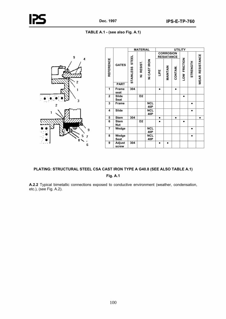
Dec. 1997
IPS-E-TP-760
100
TABLE A.1 - (see also Fig. A.1)
MATERIAL UTILITY CORROSION RESIATANCE
GATES
REF
EREN
CE
PART STA
INLE
SS S
TEEL
Ni
RES
IST.
Ni C
AST
IRO
N
LIFE
MA
INTA
IN
CO
NTA
M.
LOW
FR
ICTI
ON
STR
ENG
TH
WEA
R R
ESIS
TAN
CE
1 Frame seat
304 ● ●
2 Slide Seat
D2 ●
3 Frame NCL 40P
●
4 Slide NCL 40P
●
5 Stem 304 ● ● ● 6 Stem
Nut D2 ● ●
7 Wedge NCL 40P
●
8 Wedge Seat
NCL 40P
●
9 Adjust screw
304 ● ●
PLATING: STRUCTURAL STEEL CSA CAST IRON TYPE A G40.8 (SEE ALSO TABLE A.1)
Fig. A.1
A.2.2 Typical bimetallic connections exposed to conductive environment (weather, condensation, etc.), (see Fig. A.2).
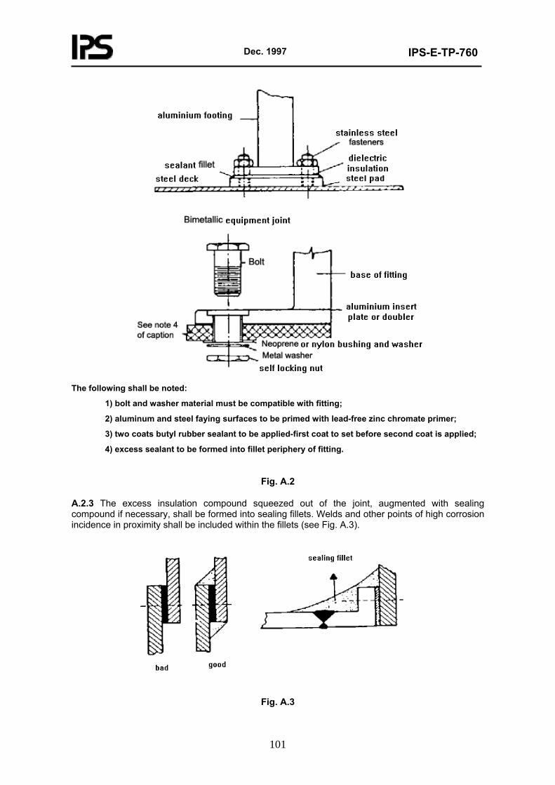
Dec. 1997
IPS-E-TP-760
101
The following shall be noted:
1) bolt and washer material must be compatible with fitting;
2) aluminum and steel faying surfaces to be primed with lead-free zinc chromate primer;
3) two coats butyl rubber sealant to be applied-first coat to set before second coat is applied;
4) excess sealant to be formed into fillet periphery of fitting.
Fig. A.2
A.2.3 The excess insulation compound squeezed out of the joint, augmented with sealing compound if necessary, shall be formed into sealing fillets. Welds and other points of high corrosion incidence in proximity shall be included within the fillets (see Fig. A.3).
Fig. A.3
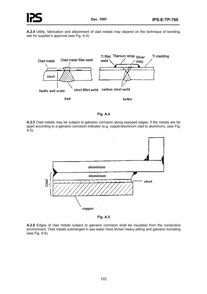
Dec. 1997
IPS-E-TP-760
102
A.2.4 Utility, fabrication and attachment of clad metals may depend on the technique of bonding; ask for supplier’s approval (see Fig. A.4).
Fig. A.4
A.2.5 Clad metals may be subject to galvanic corrosion along exposed edges, if the metals are far apart according to a galvanic corrosion indicator (e.g. copper/aluminum clad to aluminum), (see Fig. A.5).
Fig. A.5
A.2.6 Edges of clad metals subject to galvanic corrosion shall be insulated from the conductive environment. Clad metals submerged in sea water have shown heavy pitting and galvanic tunneling (see Fig. A.6).
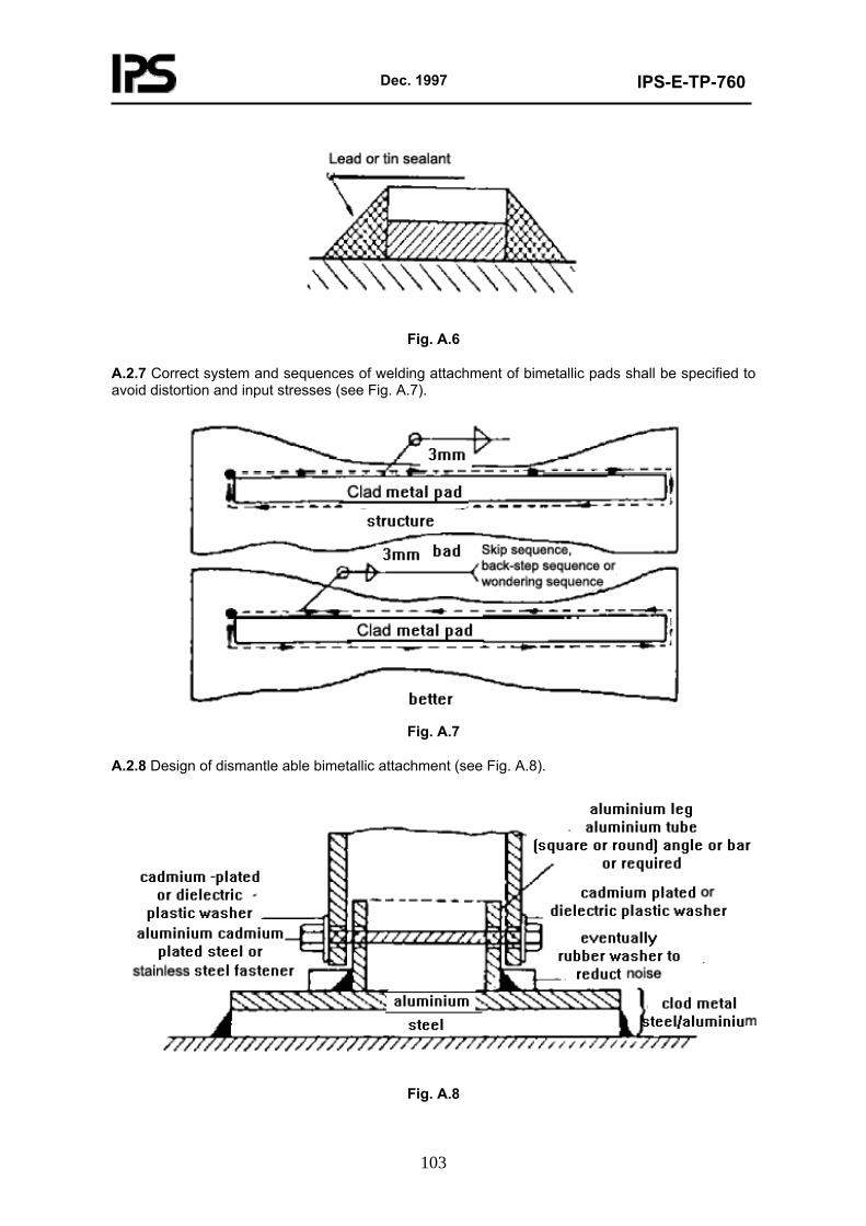
Dec. 1997
IPS-E-TP-760
103
Fig. A.6
A.2.7 Correct system and sequences of welding attachment of bimetallic pads shall be specified to avoid distortion and input stresses (see Fig. A.7).
Fig. A.7
A.2.8 Design of dismantle able bimetallic attachment (see Fig. A.8).
Fig. A.8
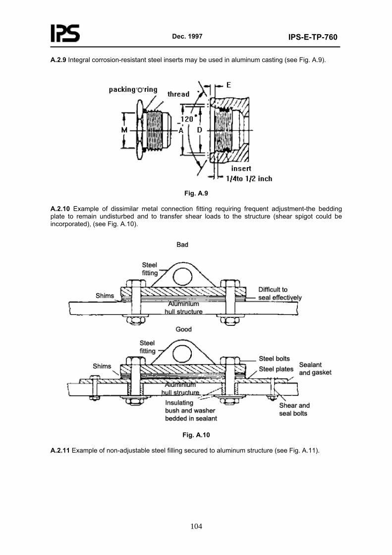
Dec. 1997
IPS-E-TP-760
104
A.2.9 Integral corrosion-resistant steel inserts may be used in aluminum casting (see Fig. A.9).
Fig. A.9
A.2.10 Example of dissimilar metal connection fitting requiring frequent adjustment-the bedding plate to remain undisturbed and to transfer shear loads to the structure (shear spigot could be incorporated), (see Fig. A.10).
Fig. A.10
A.2.11 Example of non-adjustable steel filling secured to aluminum structure (see Fig. A.11).
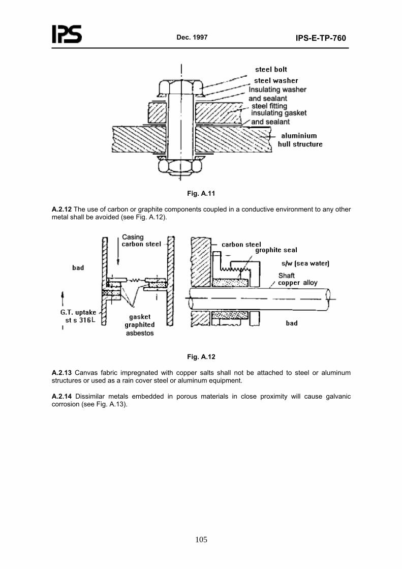
Dec. 1997
IPS-E-TP-760
105
Fig. A.11
A.2.12 The use of carbon or graphite components coupled in a conductive environment to any other metal shall be avoided (see Fig. A.12).
Fig. A.12
A.2.13 Canvas fabric impregnated with copper salts shall not be attached to steel or aluminum structures or used as a rain cover steel or aluminum equipment.
A.2.14 Dissimilar metals embedded in porous materials in close proximity will cause galvanic corrosion (see Fig. A.13).
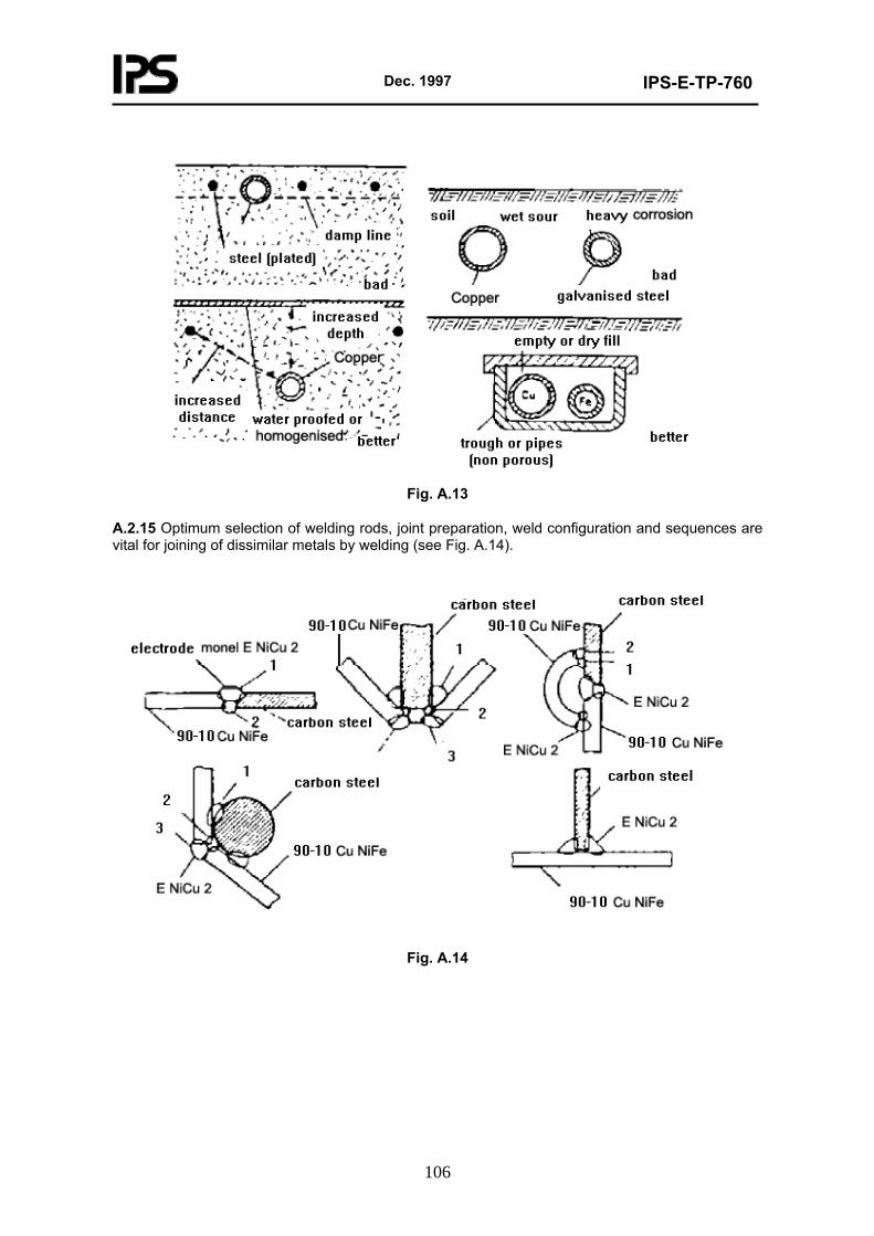
Dec. 1997
IPS-E-TP-760
106
Fig. A.13
A.2.15 Optimum selection of welding rods, joint preparation, weld configuration and sequences are vital for joining of dissimilar metals by welding (see Fig. A.14).
Fig. A.14
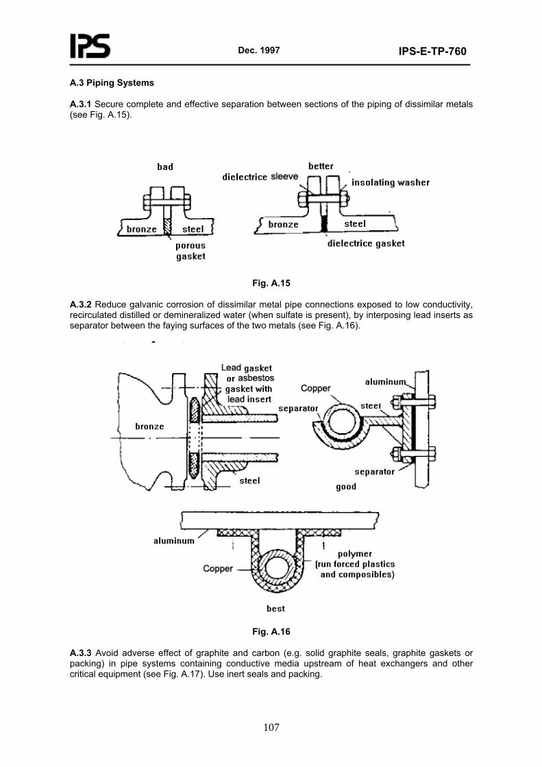
Dec. 1997
IPS-E-TP-760
107
A.3 Piping Systems
A.3.1 Secure complete and effective separation between sections of the piping of dissimilar metals (see Fig. A.15).
Fig. A.15
A.3.2 Reduce galvanic corrosion of dissimilar metal pipe connections exposed to low conductivity, recirculated distilled or demineralized water (when sulfate is present), by interposing lead inserts as separator between the faying surfaces of the two metals (see Fig. A.16).
Fig. A.16
A.3.3 Avoid adverse effect of graphite and carbon (e.g. solid graphite seals, graphite gaskets or packing) in pipe systems containing conductive media upstream of heat exchangers and other critical equipment (see Fig. A.17). Use inert seals and packing.
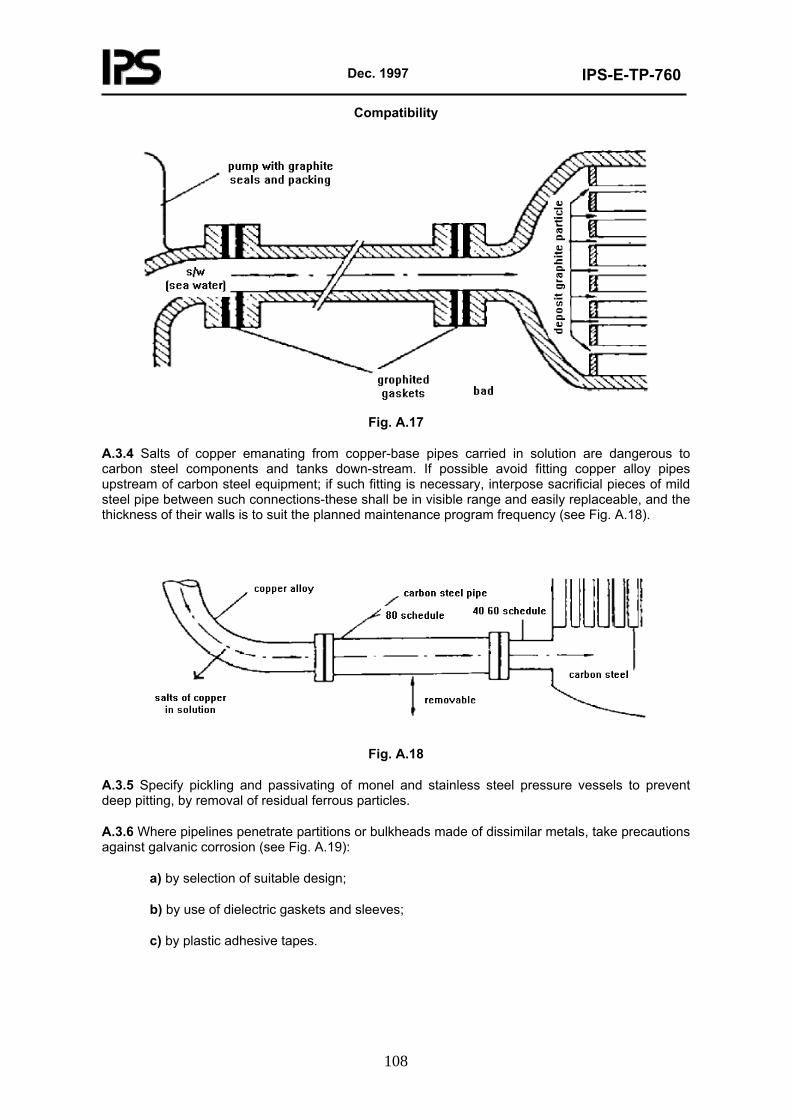
Dec. 1997
IPS-E-TP-760
108
Compatibility
Fig. A.17
A.3.4 Salts of copper emanating from copper-base pipes carried in solution are dangerous to carbon steel components and tanks down-stream. If possible avoid fitting copper alloy pipes upstream of carbon steel equipment; if such fitting is necessary, interpose sacrificial pieces of mild steel pipe between such connections-these shall be in visible range and easily replaceable, and the thickness of their walls is to suit the planned maintenance program frequency (see Fig. A.18).
Fig. A.18
A.3.5 Specify pickling and passivating of monel and stainless steel pressure vessels to prevent deep pitting, by removal of residual ferrous particles.
A.3.6 Where pipelines penetrate partitions or bulkheads made of dissimilar metals, take precautions against galvanic corrosion (see Fig. A.19):
a) by selection of suitable design;
b) by use of dielectric gaskets and sleeves;
c) by plastic adhesive tapes.
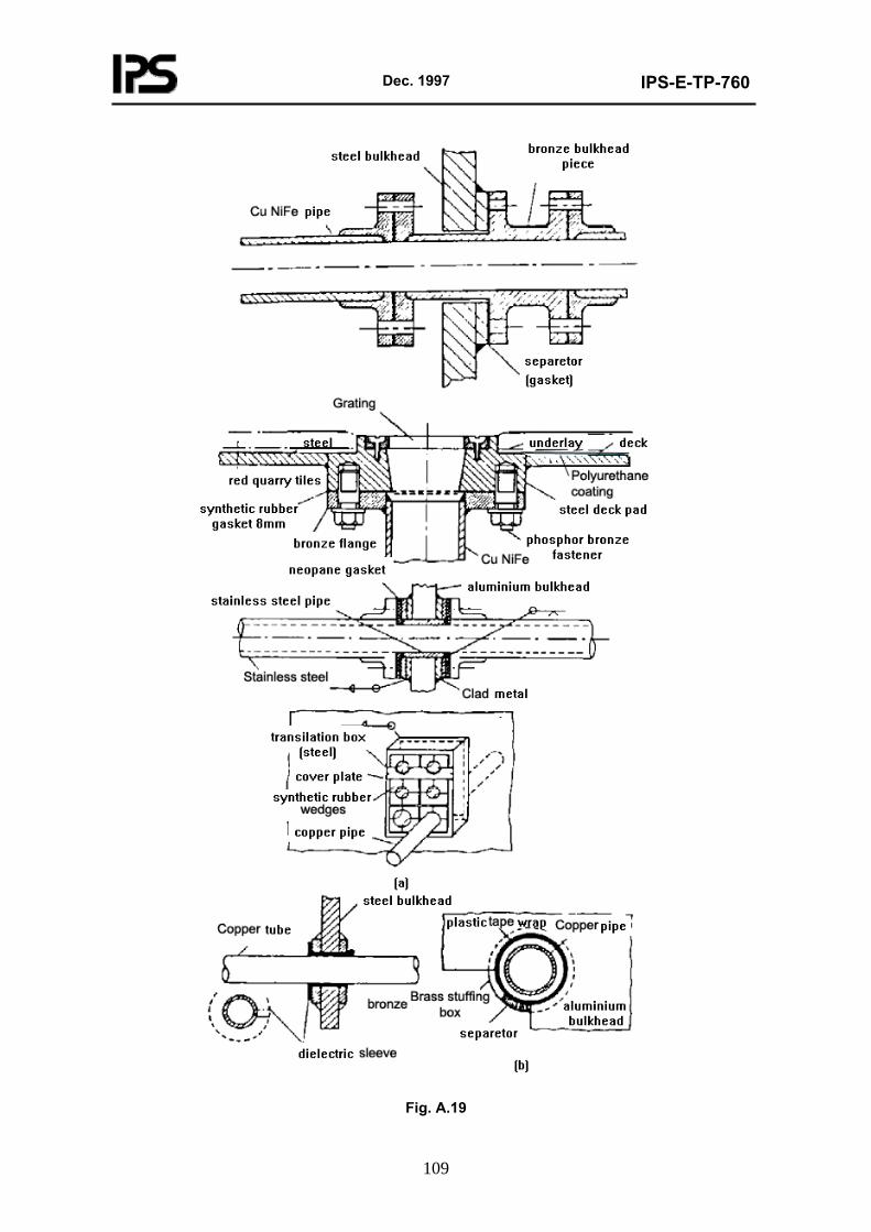
Dec. 1997
IPS-E-TP-760
109
Fig. A.19
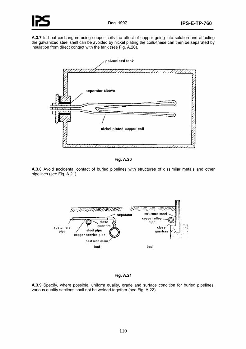
Dec. 1997
IPS-E-TP-760
110
A.3.7 In heat exchangers using copper coils the effect of copper going into solution and affecting the galvanized steel shell can be avoided by nickel plating the coils-these can then be separated by insulation from direct contact with the tank (see Fig. A.20).
Fig. A.20
A.3.8 Avoid accidental contact of buried pipelines with structures of dissimilar metals and other pipelines (see Fig. A.21).
Fig. A.21
A.3.9 Specify, where possible, uniform quality, grade and surface condition for buried pipelines, various quality sections shall not be welded together (see Fig. A.22).
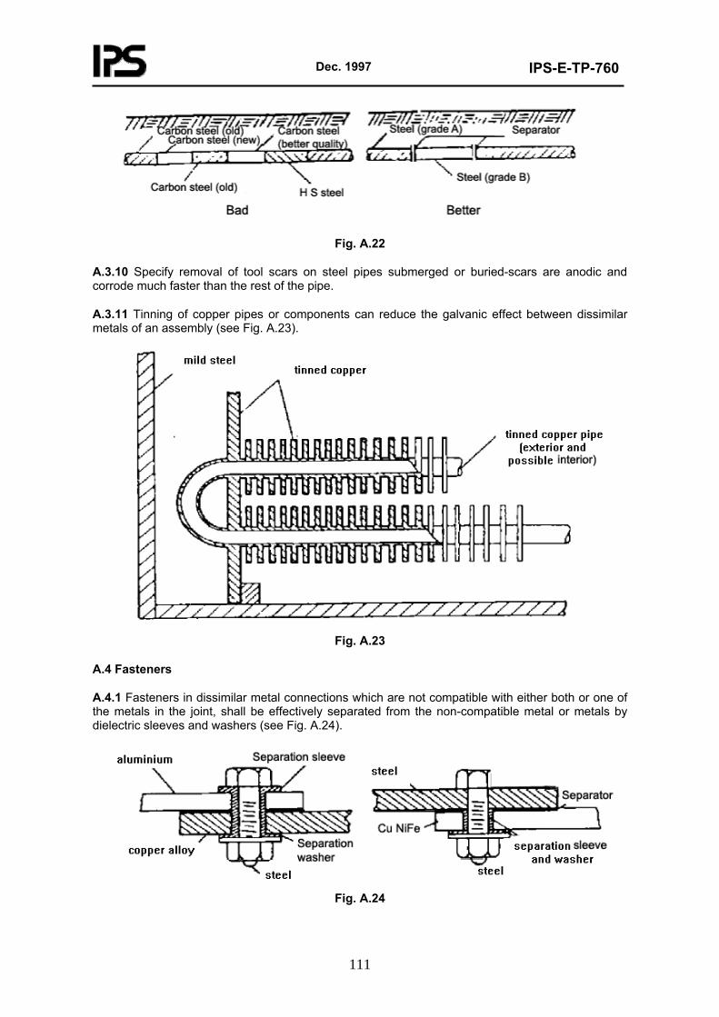
Dec. 1997
IPS-E-TP-760
111
Fig. A.22
A.3.10 Specify removal of tool scars on steel pipes submerged or buried-scars are anodic and corrode much faster than the rest of the pipe.
A.3.11 Tinning of copper pipes or components can reduce the galvanic effect between dissimilar metals of an assembly (see Fig. A.23).
Fig. A.23
A.4 Fasteners
A.4.1 Fasteners in dissimilar metal connections which are not compatible with either both or one of the metals in the joint, shall be effectively separated from the non-compatible metal or metals by dielectric sleeves and washers (see Fig. A.24).
Fig. A.24
Dec. 1997
IPS-E-TP-760
112
A.4.2 If dielectric separation of fasteners in non-compatible joints cannot be implemented, the fasteners shall be coated with zinc chromate primer and their exposed ends encapsulated (see Fig. A.25).
Fig. A.25
A.4.3 For dissimilar metal connections (aluminum to steel) in a marine environment, stainless steel fasteners installed with heads on the weather side are preferred. Fastener to be dipped in zinc chromate primer or sealing compound. If stainless steel cannot be used the exposed ends of fasteners shall be encapsulated.
A.5 Encapsulation, Sealing and Enveloping
If exclusion of access of environment to bimetallic joint by geometrical arrangement is not possible, use sealing, encapsulating or enveloping with shrinkable plastic (see Fig. A.26 a, b, c, d):
a) Plastic caps containing mastic;
b) Potting compounds (i.e. solventless epoxide) cast;
c) Total or partial envelopment with shrinkable plastics (air and watertight) or plastic films;
d) Application of moisture-proof coating or organic sealant.
Dec. 1997
IPS-E-TP-760
113
(d)
Fig. A.26
A.6 Electrical and Electronic Equipment
A.6.1 Restrict use of dissimilar metal connections to compatible metals.
A.6.2 If dissimilar metals in contact must be used, cathodic part shall be smaller than the anodic part, whenever practicable.
A.6.3 Avoid galvanic couple connections for critical assemblies (safety or operation).
A.6.4 Tin-or nickel-plated parts may be mounted on aluminum chassis direct; for exterior applications, nickel-plated parts shall not be in contact with aluminum without dielectric separator.
A.6.5 Where electrical cables penetrate a dissimilar metal partition or bulkhead, precautions against galvanic corrosion shall be taken.
A.6.6 Cadmium-or zinc-plated parts or zinc-base alloy parts shall not be used within or in the proximity of electrical equipment subject to phenolic vapors emanating from insulating materials, varnishes or encapsulating compounds.
A.6.7 An aluminum alloy 5052 gasket installed between the two metals shall separate A.6.7
Dec. 1997
IPS-E-TP-760
114
connections between magnesium and a dissimilar metal. Connections between magnesium and a dissimilar metal shall be separated by an aluminum alloy 5052 gasket installed between the two metals, and the joint shall be sealed.
A.6.8 Adequate precautions shall be taken against galvanic corrosion for cable armour grounding at bulkhead penetrations (see Fig. A.27).
Fig. A.27
A.7 Grounding and Bonding of Electrical Equipment
A.7.1 Electrical circuits and equipment, especially dc generators, shall be so designed that exposed parts or other surface-conductive materials are at ground potential at all times.
A.7.2 When grounding cable and structure are compatible, grounding, when practicable, shall be arranged by means of a bus-strap or shear-splice joint adequately insulated on the exterior (see Fig. A.28, a, b, c).
a) Preferred
Dec. 1997
IPS-E-TP-760
115
b) Typical Grounding in Generation Station
c) Typical Interior Wiring System with Neutral Ground at the Service Entrance (see next
page)
Fig. A.28
A.7.3 Copper alloy grounding conductors shall not be directly attached to steel or aluminum strength structures or pipe systems but to a suitable sacrificial bracket. The material of the bracket shall be compatible with the structure and a good conductor of electricity.
A.7.4 For provision of electromagnetic compatibility for bonding by selected surface finish see 10.6.
A.7.5 Bonds made by conductive gaskets or adhesives and involving dissimilar metal contact shall be sealed with an organic sealant (see Fig. A.29).
Fig. A.29
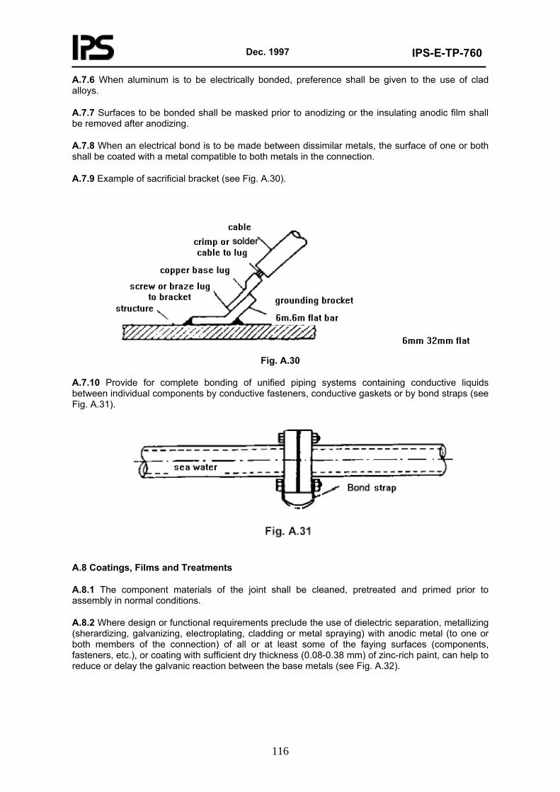
Dec. 1997
IPS-E-TP-760
116
A.7.6 When aluminum is to be electrically bonded, preference shall be given to the use of clad alloys.
A.7.7 Surfaces to be bonded shall be masked prior to anodizing or the insulating anodic film shall be removed after anodizing.
A.7.8 When an electrical bond is to be made between dissimilar metals, the surface of one or both shall be coated with a metal compatible to both metals in the connection.
A.7.9 Example of sacrificial bracket (see Fig. A.30).
Fig. A.30
A.7.10 Provide for complete bonding of unified piping systems containing conductive liquids between individual components by conductive fasteners, conductive gaskets or by bond straps (see Fig. A.31).
A.8 Coatings, Films and Treatments
A.8.1 The component materials of the joint shall be cleaned, pretreated and primed prior to assembly in normal conditions.
A.8.2 Where design or functional requirements preclude the use of dielectric separation, metallizing (sherardizing, galvanizing, electroplating, cladding or metal spraying) with anodic metal (to one or both members of the connection) of all or at least some of the faying surfaces (components, fasteners, etc.), or coating with sufficient dry thickness (0.08-0.38 mm) of zinc-rich paint, can help to reduce or delay the galvanic reaction between the base metals (see Fig. A.32).
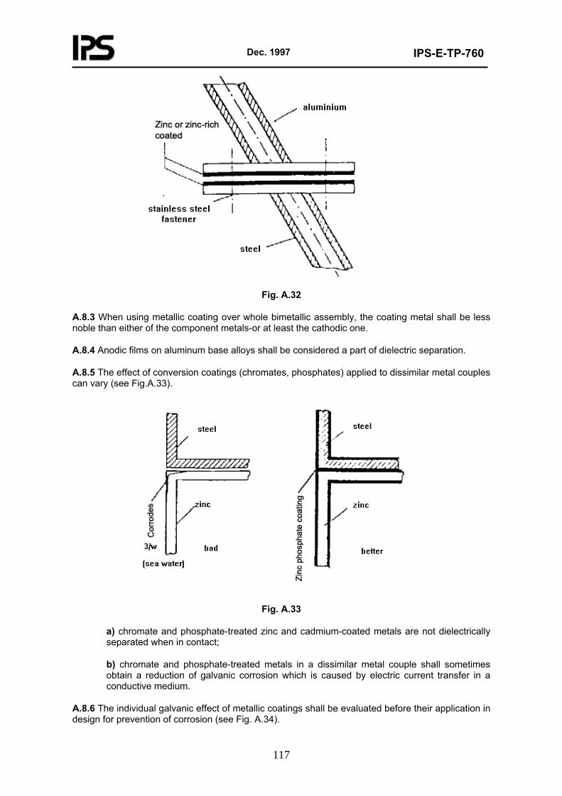
Dec. 1997
IPS-E-TP-760
117
Fig. A.32
A.8.3 When using metallic coating over whole bimetallic assembly, the coating metal shall be less noble than either of the component metals-or at least the cathodic one.
A.8.4 Anodic films on aluminum base alloys shall be considered a part of dielectric separation.
A.8.5 The effect of conversion coatings (chromates, phosphates) applied to dissimilar metal couples can vary (see Fig.A.33).
Fig. A.33
a) chromate and phosphate-treated zinc and cadmium-coated metals are not dielectrically separated when in contact;
b) chromate and phosphate-treated metals in a dissimilar metal couple shall sometimes obtain a reduction of galvanic corrosion which is caused by electric current transfer in a conductive medium.
A.8.6 The individual galvanic effect of metallic coatings shall be evaluated before their application in design for prevention of corrosion (see Fig. A.34).
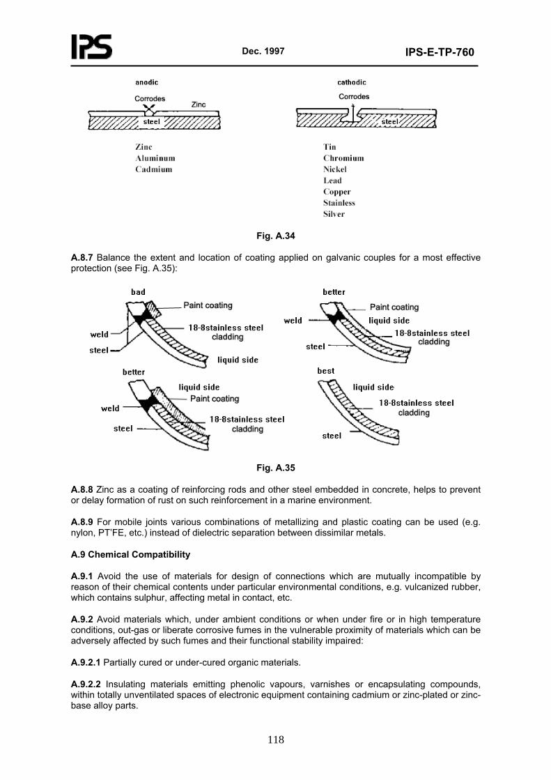
Dec. 1997
IPS-E-TP-760
118
Fig. A.34
A.8.7 Balance the extent and location of coating applied on galvanic couples for a most effective protection (see Fig. A.35):
Fig. A.35
A.8.8 Zinc as a coating of reinforcing rods and other steel embedded in concrete, helps to prevent or delay formation of rust on such reinforcement in a marine environment.
A.8.9 For mobile joints various combinations of metallizing and plastic coating can be used (e.g. nylon, PT’FE, etc.) instead of dielectric separation between dissimilar metals.
A.9 Chemical Compatibility
A.9.1 Avoid the use of materials for design of connections which are mutually incompatible by reason of their chemical contents under particular environmental conditions, e.g. vulcanized rubber, which contains sulphur, affecting metal in contact, etc.
A.9.2 Avoid materials which, under ambient conditions or when under fire or in high temperature conditions, out-gas or liberate corrosive fumes in the vulnerable proximity of materials which can be adversely affected by such fumes and their functional stability impaired:
A.9.2.1 Partially cured or under-cured organic materials.
A.9.2.2 Insulating materials emitting phenolic vapours, varnishes or encapsulating compounds, within totally unventilated spaces of electronic equipment containing cadmium or zinc-plated or zinc-base alloy parts.
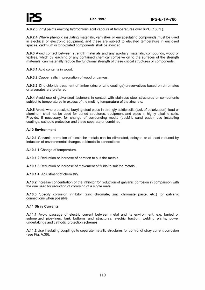
Dec. 1997
IPS-E-TP-760
119
A.9.2.3 Vinyl paints emitting hydrochloric acid vapours at temperatures over 66°C (150°F).
A.9.2.4 Where phenolic insulating materials, varnishes or encapsulating compounds must be used in electrical or electronic equipment, and these are subject to elevated temperature in enclosed spaces, cadmium or zinc-plated components shall be avoided.
A.9.3 Avoid contact between strength materials and any auxiliary materials, compounds, wood or textiles, which by leaching of any contained chemical corrosive on to the surfaces of the strength materials, can materially reduce the functional strength of these critical structures or components:
A.9.3.1 Acid contents in wood.
A.9.3.2 Copper salts impregnation of wood or canvas.
A.9.3.3 Zinc chloride treatment of timber (zinc or zinc coatings)-preservatives based on chromates or arsenates are preferred.
A.9.4 Avoid use of galvanized fasteners in contact with stainless steel structures or components subject to temperatures in excess of the melting temperature of the zinc, etc.
A.9.5 Avoid, where possible, burying steel pipes in strongly acidic soils (lack of polarization); lead or aluminum shall not be used for buried structures, equipment and pipes in highly alkaline soils. Provide, if necessary, for change of surrounding media (backfill, sand pads); use insulating coatings, cathodic protection and these separate or combined.
A.10 Environment
A.10.1 Galvanic corrosion of dissimilar metals can be eliminated, delayed or at least reduced by induction of environmental changes at bimetallic connections:
A.10.1.1 Change of temperature.
A.10.1.2 Reduction or increase of aeration to suit the metals.
A.10.1.3 Reduction or increase of movement of fluids to suit the metals.
A.10.1.4 Adjustment of chemistry.
A.10.2 Increase concentration of the inhibitor for reduction of galvanic corrosion in comparison with the one used for reduction of corrosion of a single metal.
A.10.3 Specify corrosion inhibitor (zinc chromate, zinc chromate paste, etc.) for galvanic connections when possible.
A.11 Stray Currents
A.11.1 Avoid passage of electric current between metal and its environment; e.g. buried or submerged pipe-lines, tank bottoms and structures, electric traction, welding plants, power undertakings and cathodic protection schemes.
A.11.2 Use insulating couplings to separate metallic structures for control of stray current corrosion (see Fig. A.36).
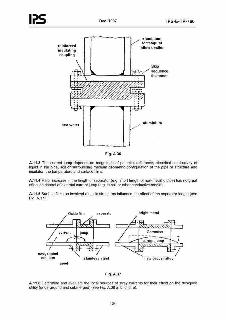
Dec. 1997
IPS-E-TP-760
120
Fig. A.36
A.11.3 The current jump depends on magnitude of potential difference, electrical conductivity of liquid in the pipe, soil or surrounding medium geometric configuration of the pipe or structure and insulator, the temperature and surface films.
A.11.4 Major increase in the length of separator (e.g. short length of non-metallic pipe) has no great effect on control of external current jump (e.g. in soil or other conductive media).
A.11.5 Surface films on involved metallic structures influence the effect of the separator length (see Fig. A.37).
Fig. A.37
A.11.6 Determine and evaluate the local sources of stray currents for their effect on the designed utility (underground and submerged) (see Fig. A.38 a, b, c, d, e).
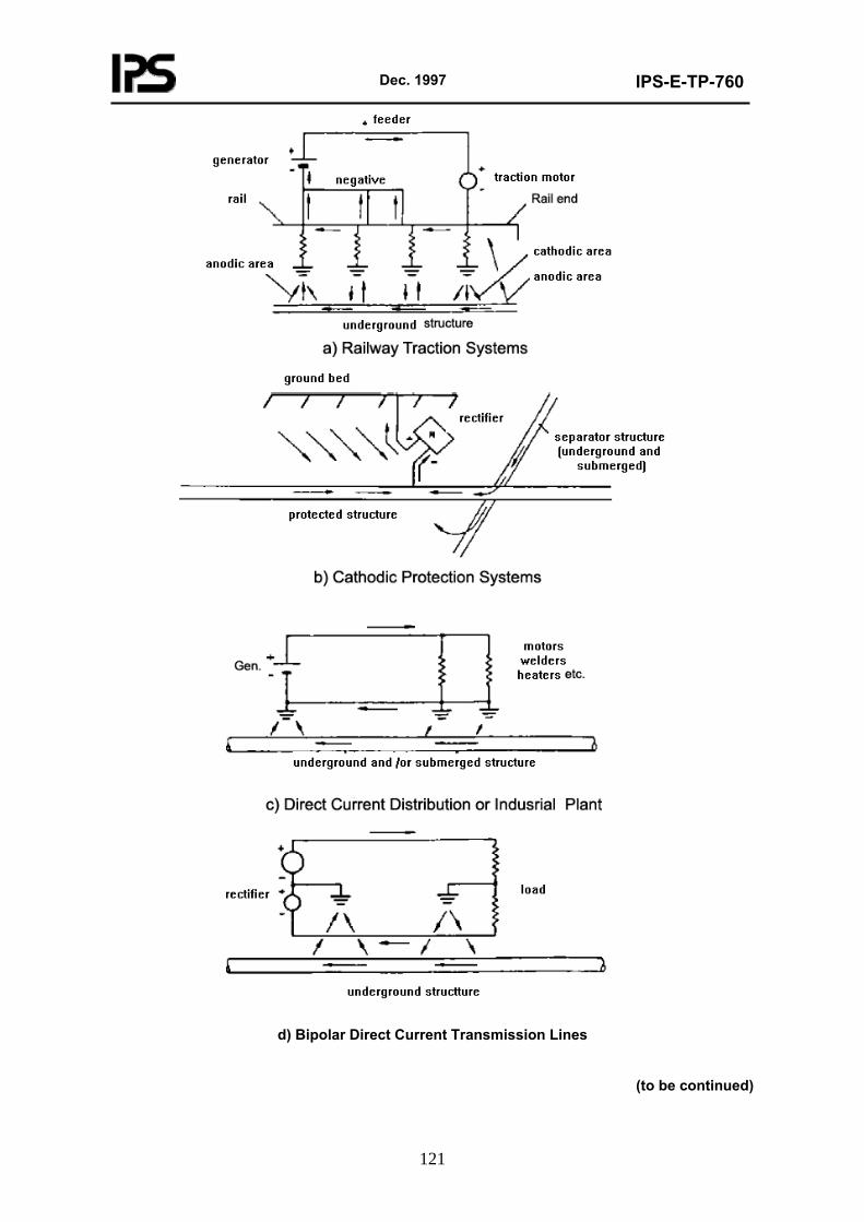
Dec. 1997
IPS-E-TP-760
121
d) Bipolar Direct Current Transmission Lines
(to be continued)
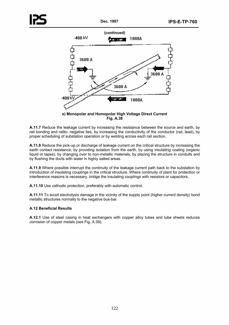
Dec. 1997
IPS-E-TP-760
122
(continued)
e) Monopolar and Homopolar High Voltage Direct Current
Fig. A.38
A.11.7 Reduce the leakage current by increasing the resistance between the source and earth, by rail bonding and railto- negative ties, by increasing the conductivity of the conductor (rail, lead), by proper scheduling of substation operation or by welding across each rail section.
A.11.8 Reduce the pick-up or discharge of leakage current on the critical structure by increasing the earth contact resistance, by providing isolation from the earth, by using insulating coating (organic liquid or tapes), by changing over to non-metallic materials, by placing the structure in conduits and by flushing the ducts with water in highly salted areas.
A.11.9 Where possible interrupt the continuity of the leakage current path back to the substation by introduction of insulating couplings in the critical structure. Where continuity of plant for protection or interference reasons is necessary, bridge the insulating couplings with resistors or capacitors.
A.11.10 Use cathodic protection, preferably with automatic control.
A.11.11 To avoid electrolysis damage in the vicinity of the supply point (higher current density) bond metallic structures normally to the negative bus-bar.
A.12 Beneficial Results
A.12.1 Use of steel casing in heat exchangers with copper alloy tubes and tube sheets reduces corrosion of copper metals (see Fig. A.39).
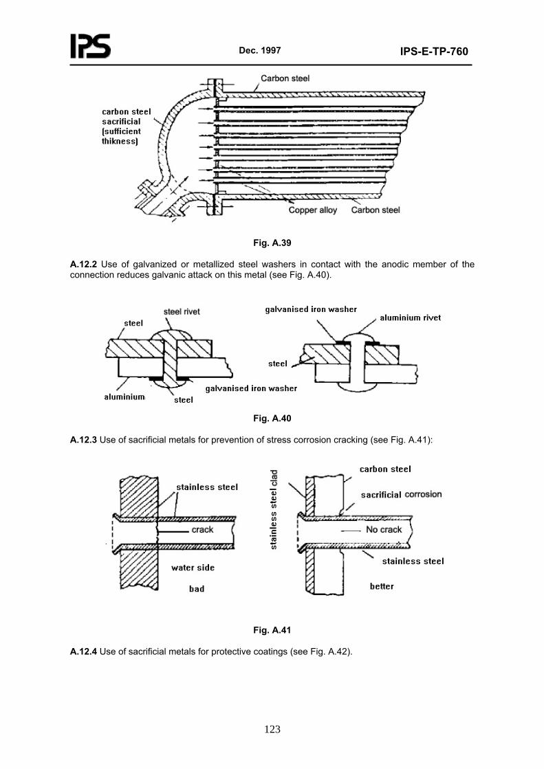
Dec. 1997
IPS-E-TP-760
123
Fig. A.39
A.12.2 Use of galvanized or metallized steel washers in contact with the anodic member of the connection reduces galvanic attack on this metal (see Fig. A.40).
Fig. A.40
A.12.3 Use of sacrificial metals for prevention of stress corrosion cracking (see Fig. A.41):
Fig. A.41
A.12.4 Use of sacrificial metals for protective coatings (see Fig. A.42).
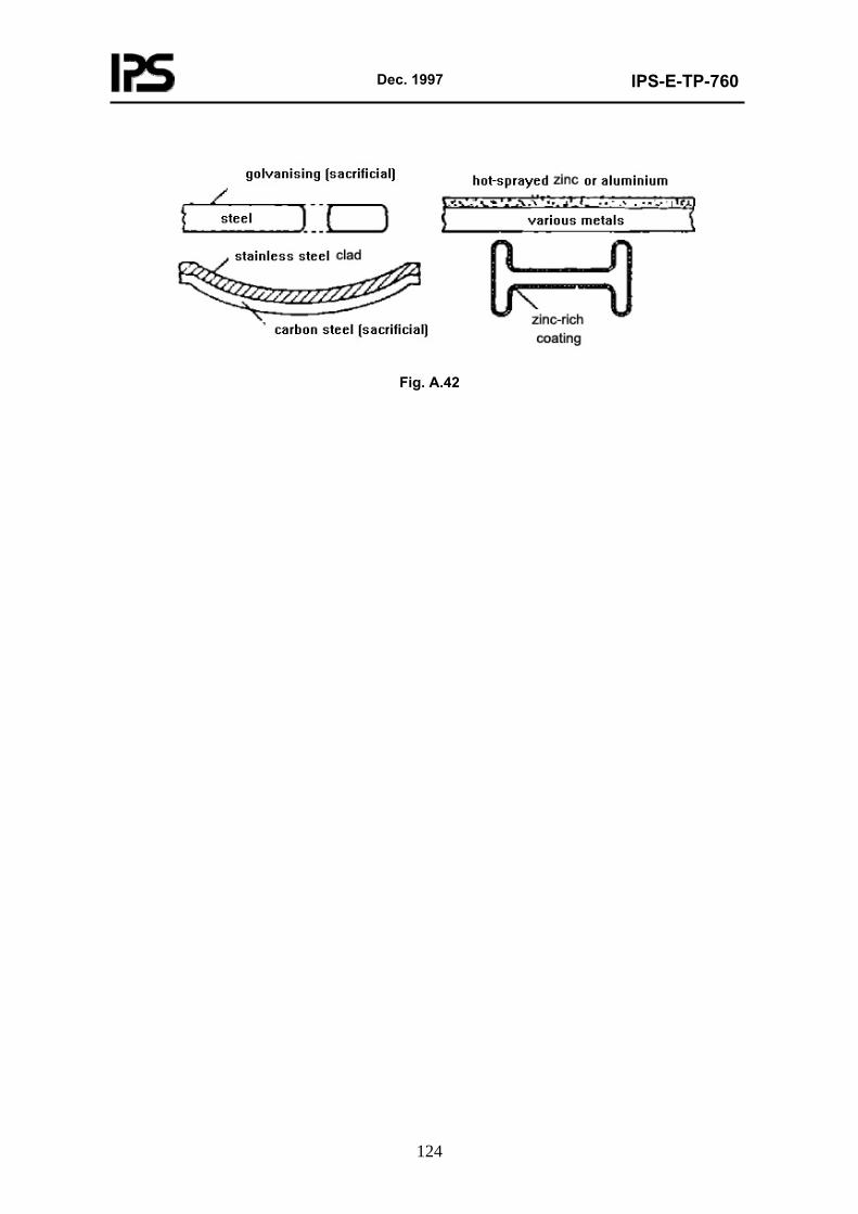
Dec. 1997
IPS-E-TP-760
124
Fig. A.42
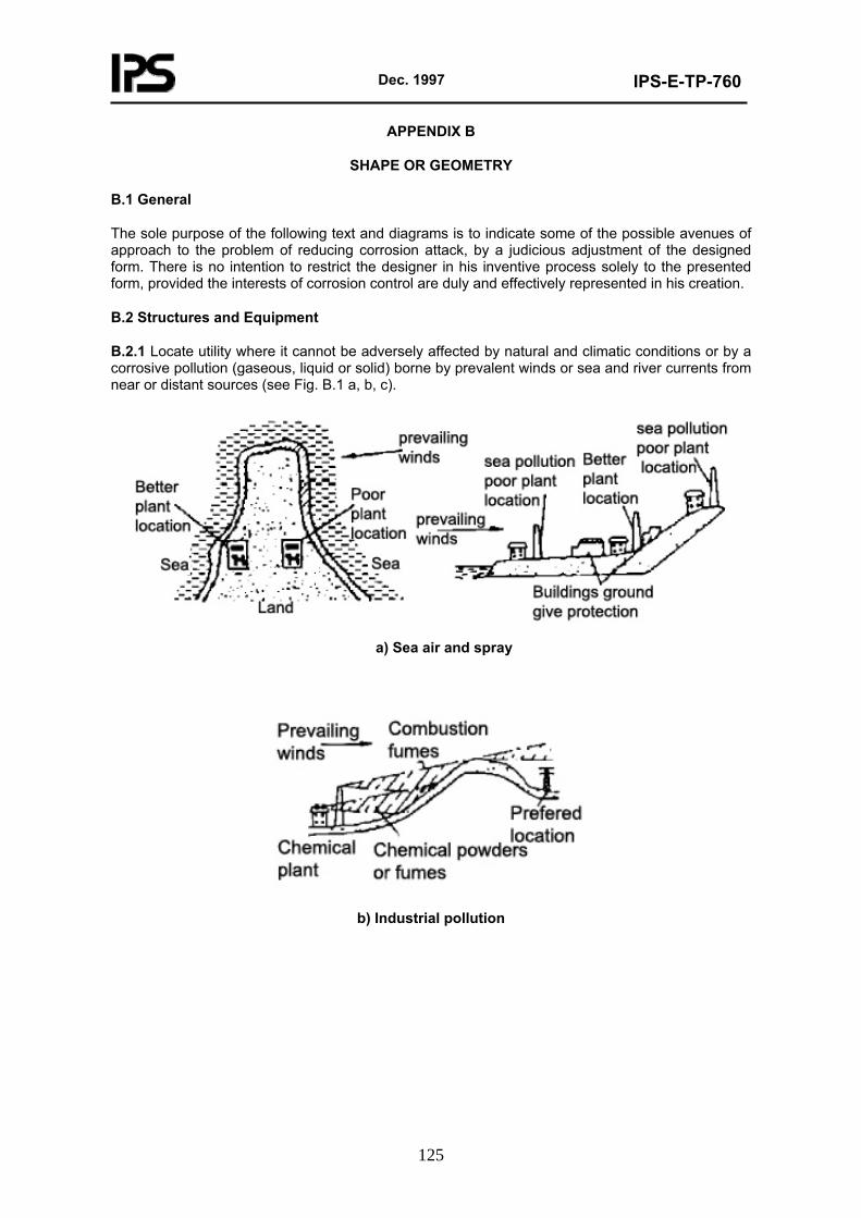
Dec. 1997
IPS-E-TP-760
125
APPENDIX B
SHAPE OR GEOMETRY
B.1 General
The sole purpose of the following text and diagrams is to indicate some of the possible avenues of approach to the problem of reducing corrosion attack, by a judicious adjustment of the designed form. There is no intention to restrict the designer in his inventive process solely to the presented form, provided the interests of corrosion control are duly and effectively represented in his creation.
B.2 Structures and Equipment
B.2.1 Locate utility where it cannot be adversely affected by natural and climatic conditions or by a corrosive pollution (gaseous, liquid or solid) borne by prevalent winds or sea and river currents from near or distant sources (see Fig. B.1 a, b, c).
a) Sea air and spray
b) Industrial pollution
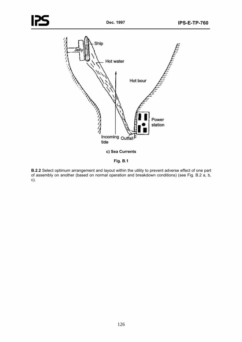
Dec. 1997
IPS-E-TP-760
126
c) Sea Currents
Fig. B.1
B.2.2 Select optimum arrangement and layout within the utility to prevent adverse effect of one part of assembly on another (based on normal operation and breakdown conditions) (see Fig. B.2 a, b, c).
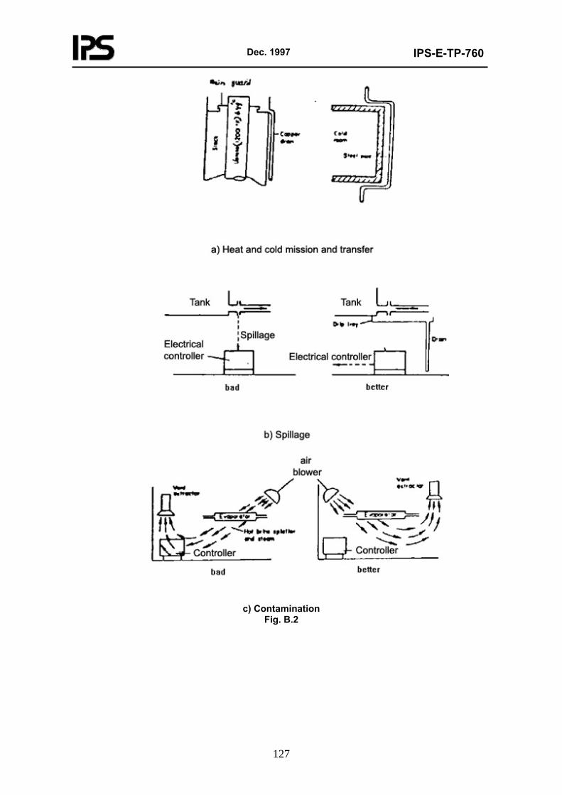
Dec. 1997
IPS-E-TP-760
127
c) Contamination
Fig. B.2
Dec. 1997
IPS-E-TP-760
128
B.2.3 Avoid undrainable traps accumulating liquids and absorbent solid wastes (see Fig. B.3).
Fig. B.3
B.2.4 Provide adequate drainage, scuppers and limber holes (see Fig. B.4). Scuppers shall be fitted at the lowest possible position in a space to ensure full drainage of space. The ship’s movement shall be taken into consideration when choosing optimum position for a scupper.
Fig. B.4
B.2.5 Design self-draining structures (see Fig. B.5).
Dec. 1997
IPS-E-TP-760
129
Fig. B.5
B.2.6 Prevent access of abrasives and other solid contaminants to critical spaces (see Fig. B.6).
Fig. B.6
B.2.7 Prevent condensation in critical spaces by selected geometry (see Fig. B.7).
Dec. 1997
IPS-E-TP-760
130
Fig. B.7
B.2.8 Where crevices cannot be avoided take precautions to prevent ingress of corroding by improving the geometry, fit or surface texture (see Fig. B.8).
PREVENTION OF CREVICE CORROSION-SUBMERGED STAINLESS STEEL FASTENERS
Fig. B.8
B.2.9 Where possible avoid laps and crevices or seal these effectively, especially in areas of heat transfer, between metal and a porous material or where aqueous environment contains inorganic chemicals or dissolved oxygen (see Fig. B.9).
Dec. 1997
IPS-E-TP-760
131
Fig. B.9
B.2.10 Face laps downwards on exposed surfaces (see Fig. B.10).
Fig. B.10
B.2.11 Make every effort to give design a shape or form, which will reduce the effect of excessive velocity, turbulence of flow and formation of gas, bubbles (see Fig. B.11 a, b, c, d, e).
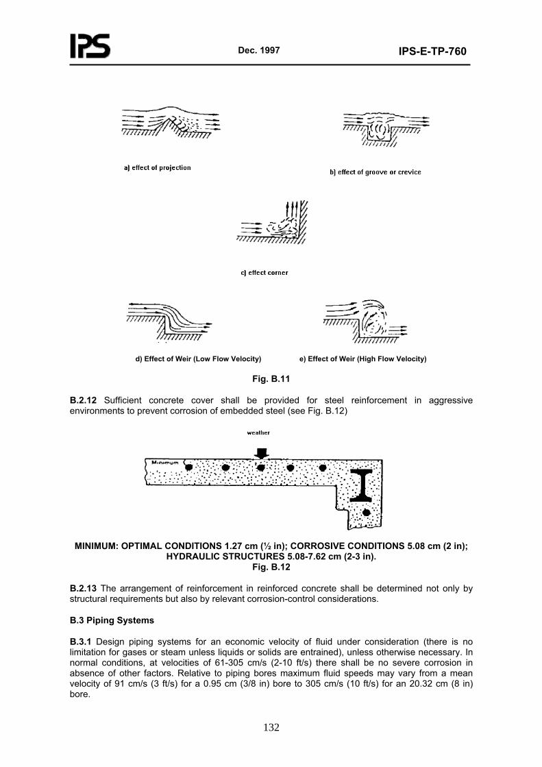
Dec. 1997
IPS-E-TP-760
132
d) Effect of Weir (Low Flow Velocity) e) Effect of Weir (High Flow Velocity)
Fig. B.11
B.2.12 Sufficient concrete cover shall be provided for steel reinforcement in aggressive environments to prevent corrosion of embedded steel (see Fig. B.12)
MINIMUM: OPTIMAL CONDITIONS 1.27 cm (½ in); CORROSIVE CONDITIONS 5.08 cm (2 in);
HYDRAULIC STRUCTURES 5.08-7.62 cm (2-3 in). Fig. B.12
B.2.13 The arrangement of reinforcement in reinforced concrete shall be determined not only by structural requirements but also by relevant corrosion-control considerations.
B.3 Piping Systems
B.3.1 Design piping systems for an economic velocity of fluid under consideration (there is no limitation for gases or steam unless liquids or solids are entrained), unless otherwise necessary. In normal conditions, at velocities of 61-305 cm/s (2-10 ft/s) there shall be no severe corrosion in absence of other factors. Relative to piping bores maximum fluid speeds may vary from a mean velocity of 91 cm/s (3 ft/s) for a 0.95 cm (3/8 in) bore to 305 cm/s (10 ft/s) for an 20.32 cm (8 in) bore.
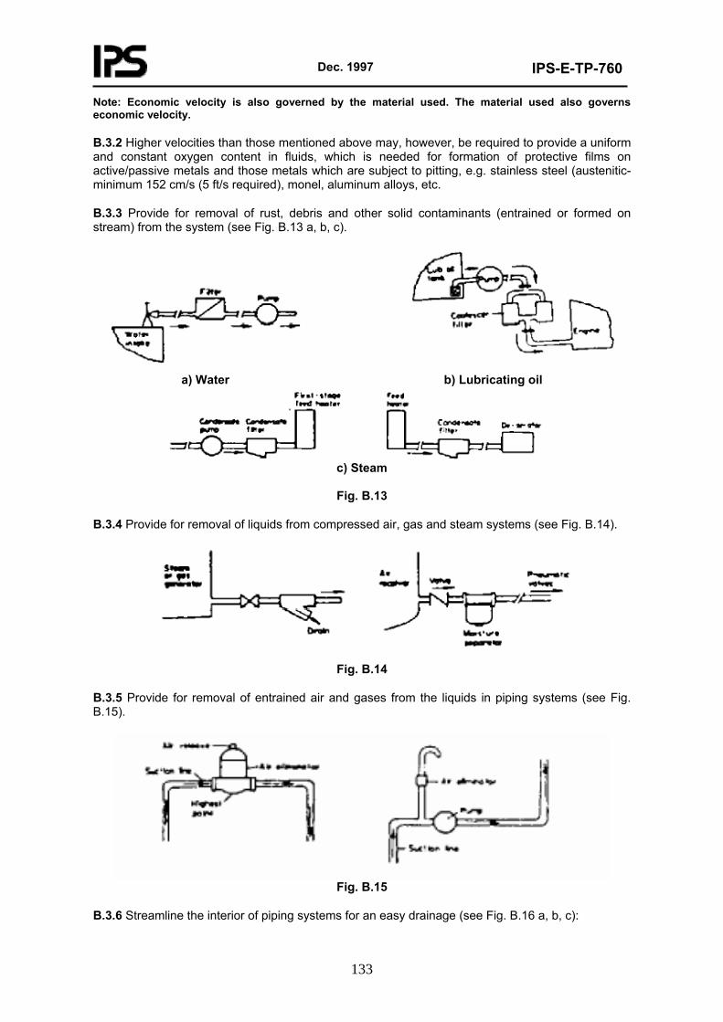
Dec. 1997
IPS-E-TP-760
133
Note: Economic velocity is also governed by the material used. The material used also governs economic velocity.
B.3.2 Higher velocities than those mentioned above may, however, be required to provide a uniform and constant oxygen content in fluids, which is needed for formation of protective films on active/passive metals and those metals which are subject to pitting, e.g. stainless steel (austenitic-minimum 152 cm/s (5 ft/s required), monel, aluminum alloys, etc.
B.3.3 Provide for removal of rust, debris and other solid contaminants (entrained or formed on stream) from the system (see Fig. B.13 a, b, c).
a) Water b) Lubricating oil
c) Steam
Fig. B.13
B.3.4 Provide for removal of liquids from compressed air, gas and steam systems (see Fig. B.14).
Fig. B.14
B.3.5 Provide for removal of entrained air and gases from the liquids in piping systems (see Fig. B.15).
Fig. B.15
B.3.6 Streamline the interior of piping systems for an easy drainage (see Fig. B.16 a, b, c):
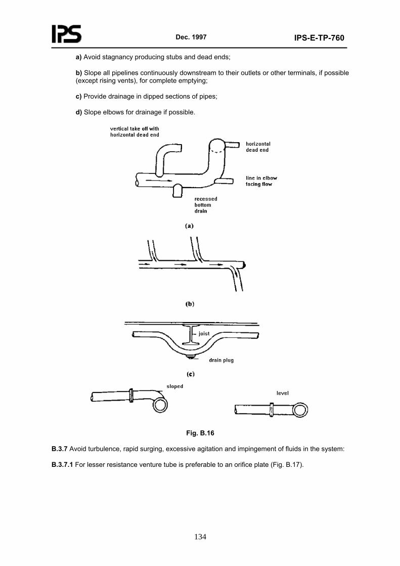
Dec. 1997
IPS-E-TP-760
134
a) Avoid stagnancy producing stubs and dead ends;
b) Slope all pipelines continuously downstream to their outlets or other terminals, if possible (except rising vents), for complete emptying;
c) Provide drainage in dipped sections of pipes;
d) Slope elbows for drainage if possible.
Fig. B.16
B.3.7 Avoid turbulence, rapid surging, excessive agitation and impingement of fluids in the system:
B.3.7.1 For lesser resistance venture tube is preferable to an orifice plate (Fig. B.17).
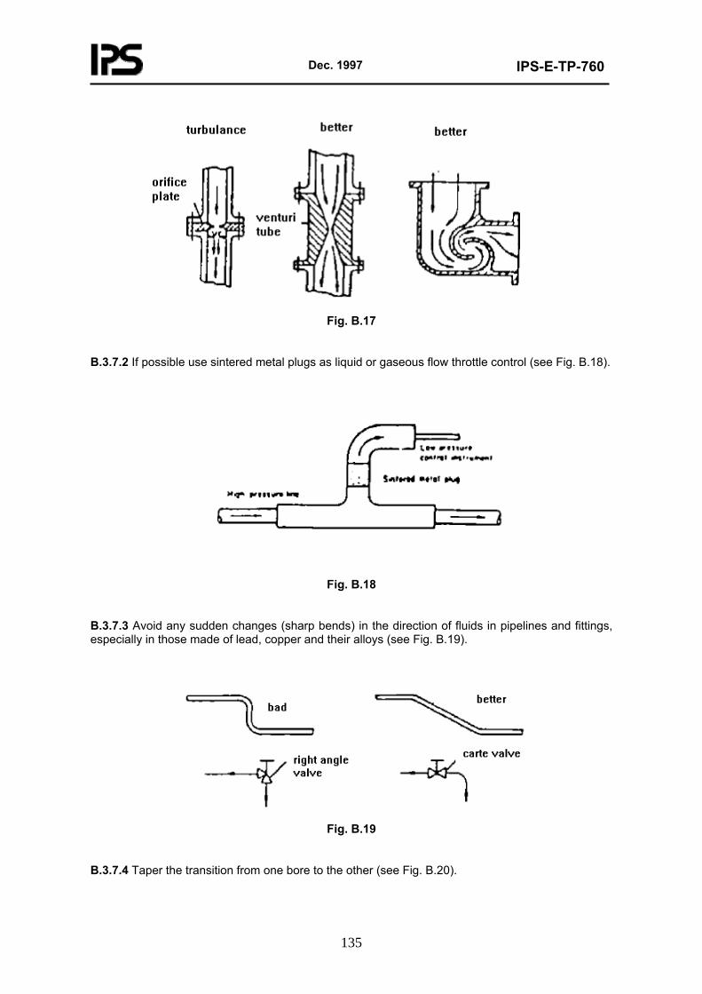
Dec. 1997
IPS-E-TP-760
135
Fig. B.17
B.3.7.2 If possible use sintered metal plugs as liquid or gaseous flow throttle control (see Fig. B.18).
Fig. B.18
B.3.7.3 Avoid any sudden changes (sharp bends) in the direction of fluids in pipelines and fittings, especially in those made of lead, copper and their alloys (see Fig. B.19).
Fig. B.19
B.3.7.4 Taper the transition from one bore to the other (see Fig. B.20).
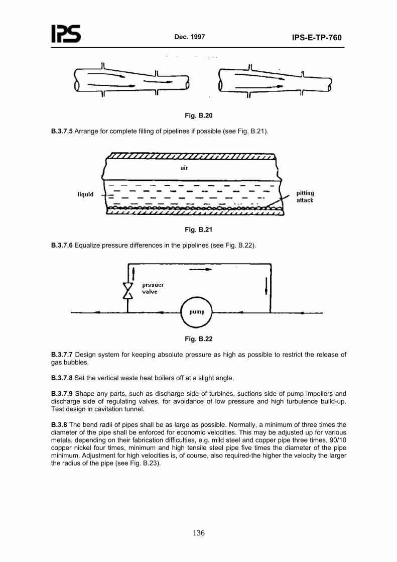
Dec. 1997
IPS-E-TP-760
136
Fig. B.20
B.3.7.5 Arrange for complete filling of pipelines if possible (see Fig. B.21).
Fig. B.21
B.3.7.6 Equalize pressure differences in the pipelines (see Fig. B.22).
Fig. B.22
B.3.7.7 Design system for keeping absolute pressure as high as possible to restrict the release of gas bubbles.
B.3.7.8 Set the vertical waste heat boilers off at a slight angle.
B.3.7.9 Shape any parts, such as discharge side of turbines, suctions side of pump impellers and discharge side of regulating valves, for avoidance of low pressure and high turbulence build-up. Test design in cavitation tunnel.
B.3.8 The bend radii of pipes shall be as large as possible. Normally, a minimum of three times the diameter of the pipe shall be enforced for economic velocities. This may be adjusted up for various metals, depending on their fabrication difficulties, e.g. mild steel and copper pipe three times, 90/10 copper nickel four times, minimum and high tensile steel pipe five times the diameter of the pipe minimum. Adjustment for high velocities is, of course, also required-the higher the velocity the larger the radius of the pipe (see Fig. B.23).
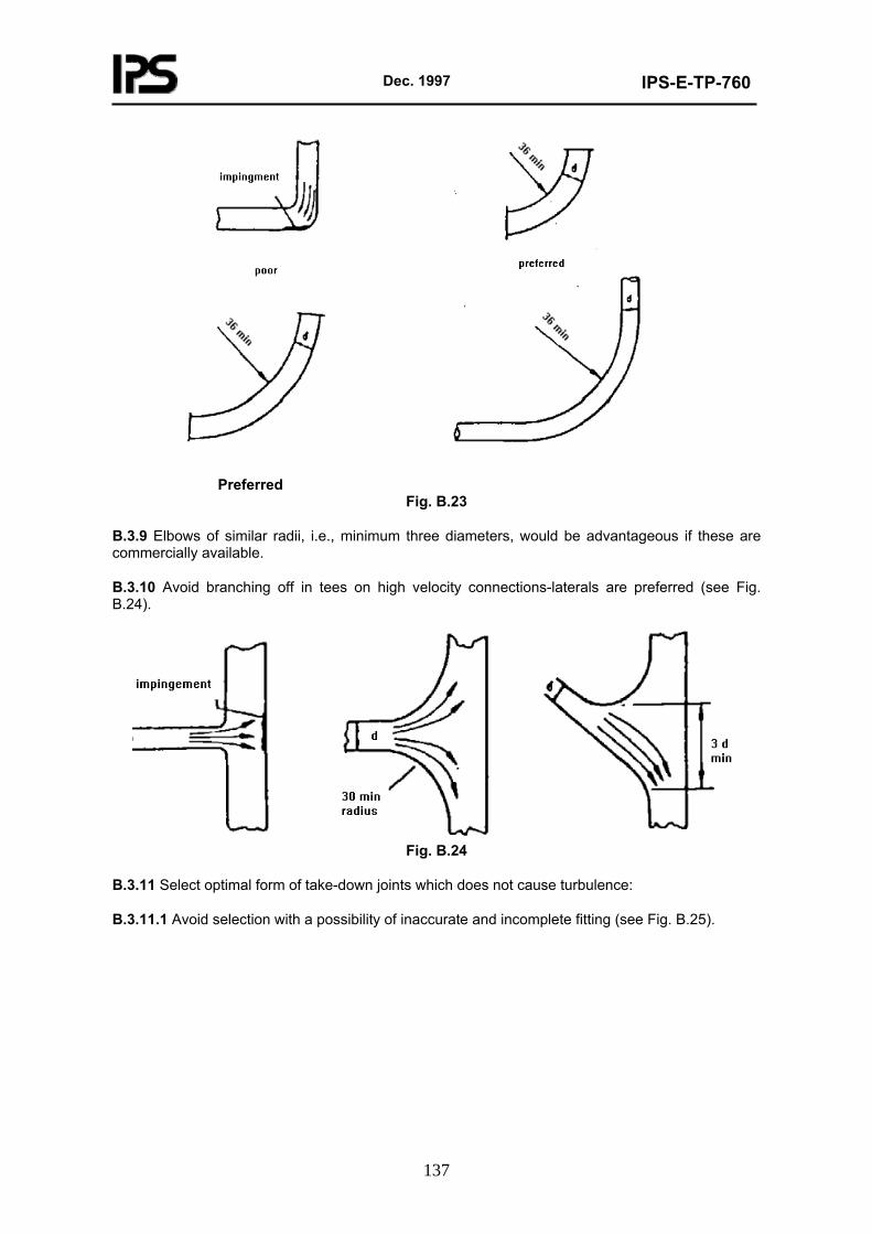
Dec. 1997
IPS-E-TP-760
137
Preferred
Fig. B.23
B.3.9 Elbows of similar radii, i.e., minimum three diameters, would be advantageous if these are commercially available.
B.3.10 Avoid branching off in tees on high velocity connections-laterals are preferred (see Fig. B.24).
Fig. B.24
B.3.11 Select optimal form of take-down joints which does not cause turbulence:
B.3.11.1 Avoid selection with a possibility of inaccurate and incomplete fitting (see Fig. B.25).
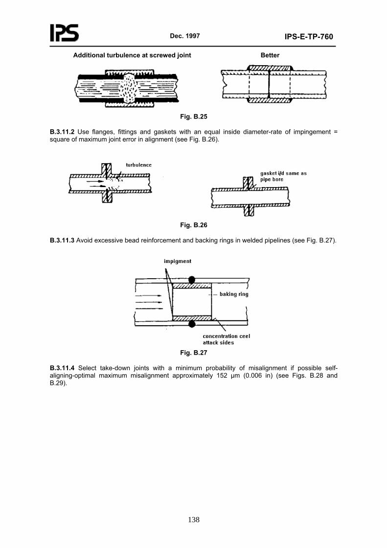
Dec. 1997
IPS-E-TP-760
138
Additional turbulence at screwed joint Better
Fig. B.25
B.3.11.2 Use flanges, fittings and gaskets with an equal inside diameter-rate of impingement = square of maximum joint error in alignment (see Fig. B.26).
Fig. B.26
B.3.11.3 Avoid excessive bead reinforcement and backing rings in welded pipelines (see Fig. B.27).
Fig. B.27
B.3.11.4 Select take-down joints with a minimum probability of misalignment if possible self-aligning-optimal maximum misalignment approximately 152 µm (0.006 in) (see Figs. B.28 and B.29).
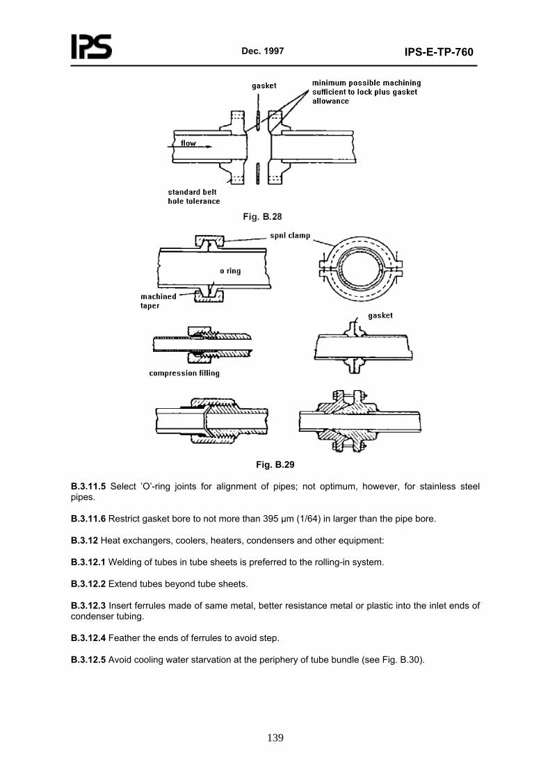
Dec. 1997
IPS-E-TP-760
139
Fig. B.29
B.3.11.5 Select ’O’-ring joints for alignment of pipes; not optimum, however, for stainless steel pipes.
B.3.11.6 Restrict gasket bore to not more than 395 µm (1/64) in larger than the pipe bore.
B.3.12 Heat exchangers, coolers, heaters, condensers and other equipment:
B.3.12.1 Welding of tubes in tube sheets is preferred to the rolling-in system.
B.3.12.2 Extend tubes beyond tube sheets.
B.3.12.3 Insert ferrules made of same metal, better resistance metal or plastic into the inlet ends of condenser tubing.
B.3.12.4 Feather the ends of ferrules to avoid step.
B.3.12.5 Avoid cooling water starvation at the periphery of tube bundle (see Fig. B.30).
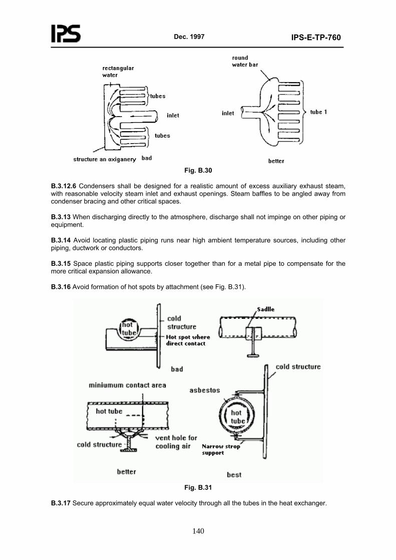
Dec. 1997
IPS-E-TP-760
140
Fig. B.30
B.3.12.6 Condensers shall be designed for a realistic amount of excess auxiliary exhaust steam, with reasonable velocity steam inlet and exhaust openings. Steam baffles to be angled away from condenser bracing and other critical spaces.
B.3.13 When discharging directly to the atmosphere, discharge shall not impinge on other piping or equipment.
B.3.14 Avoid locating plastic piping runs near high ambient temperature sources, including other piping, ductwork or conductors.
B.3.15 Space plastic piping supports closer together than for a metal pipe to compensate for the more critical expansion allowance.
B.3.16 Avoid formation of hot spots by attachment (see Fig. B.31).
Fig. B.31
B.3.17 Secure approximately equal water velocity through all the tubes in the heat exchanger.
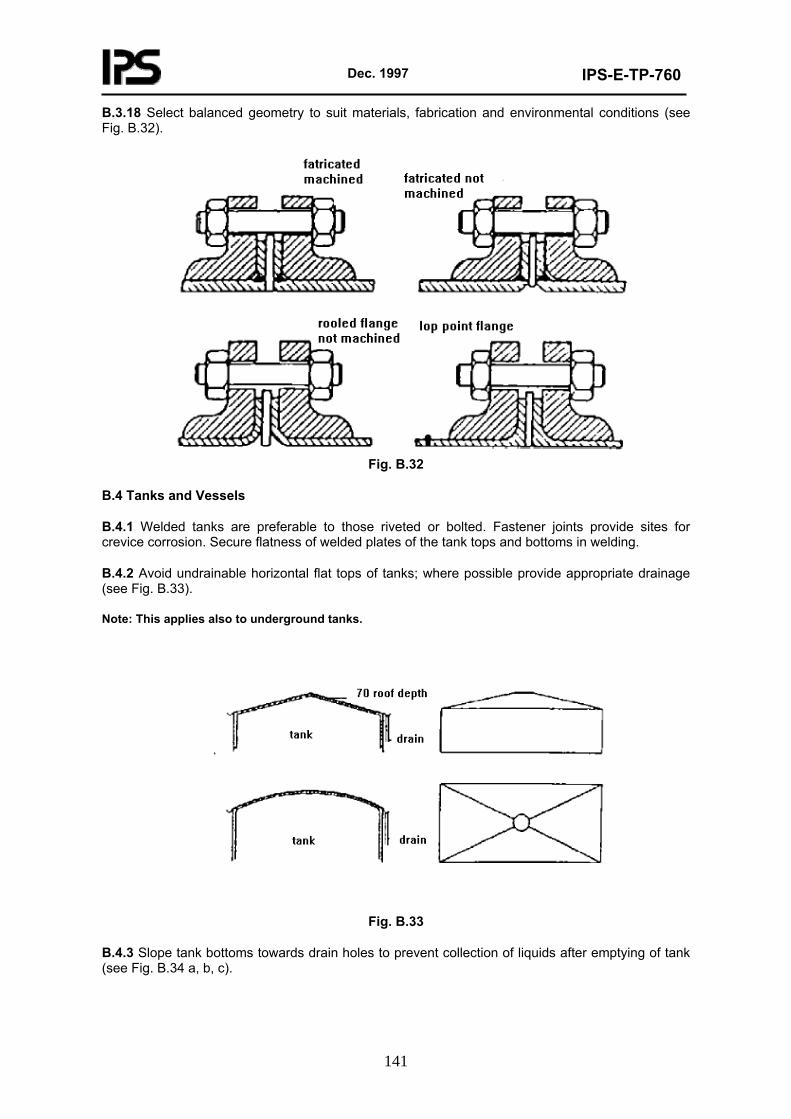
Dec. 1997
IPS-E-TP-760
141
B.3.18 Select balanced geometry to suit materials, fabrication and environmental conditions (see Fig. B.32).
Fig. B.32
B.4 Tanks and Vessels
B.4.1 Welded tanks are preferable to those riveted or bolted. Fastener joints provide sites for crevice corrosion. Secure flatness of welded plates of the tank tops and bottoms in welding.
B.4.2 Avoid undrainable horizontal flat tops of tanks; where possible provide appropriate drainage (see Fig. B.33).
Note: This applies also to underground tanks.
Fig. B.33
B.4.3 Slope tank bottoms towards drain holes to prevent collection of liquids after emptying of tank (see Fig. B.34 a, b, c).
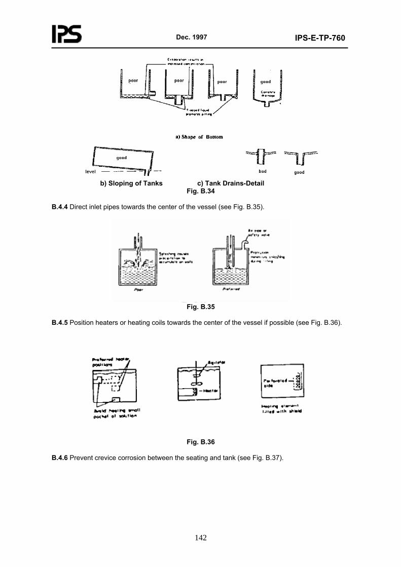
Dec. 1997
IPS-E-TP-760
142
b) Sloping of Tanks c) Tank Drains-Detail
Fig. B.34
B.4.4 Direct inlet pipes towards the center of the vessel (see Fig. B.35).
Fig. B.35
B.4.5 Position heaters or heating coils towards the center of the vessel if possible (see Fig. B.36).
Fig. B.36
B.4.6 Prevent crevice corrosion between the seating and tank (see Fig. B.37).
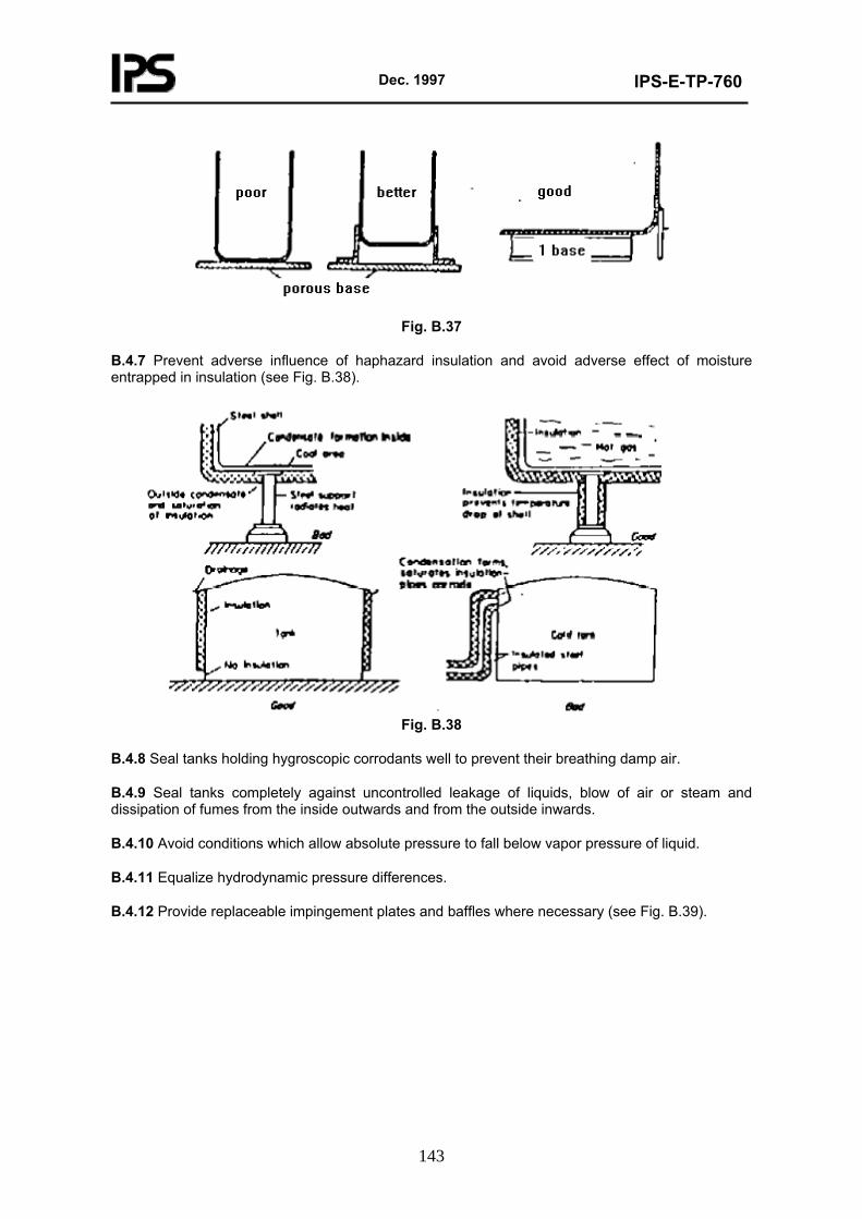
Dec. 1997
IPS-E-TP-760
143
Fig. B.37
B.4.7 Prevent adverse influence of haphazard insulation and avoid adverse effect of moisture entrapped in insulation (see Fig. B.38).
Fig. B.38
B.4.8 Seal tanks holding hygroscopic corrodants well to prevent their breathing damp air.
B.4.9 Seal tanks completely against uncontrolled leakage of liquids, blow of air or steam and dissipation of fumes from the inside outwards and from the outside inwards.
B.4.10 Avoid conditions which allow absolute pressure to fall below vapor pressure of liquid.
B.4.11 Equalize hydrodynamic pressure differences.
B.4.12 Provide replaceable impingement plates and baffles where necessary (see Fig. B.39).
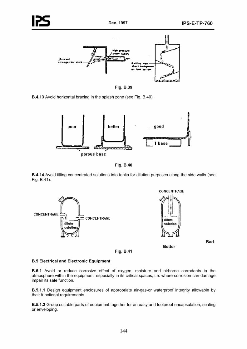
Dec. 1997
IPS-E-TP-760
144
Fig. B.39
B.4.13 Avoid horizontal bracing in the splash zone (see Fig. B.40).
Fig. B.40
B.4.14 Avoid filling concentrated solutions into tanks for dilution purposes along the side walls (see Fig. B.41).
Bad Better
Fig. B.41
B.5 Electrical and Electronic Equipment
B.5.1 Avoid or reduce corrosive effect of oxygen, moisture and airborne corrodants in the atmosphere within the equipment, especially in its critical spaces, i.e. where corrosion can damage impair its safe function.
B.5.1.1 Design equipment enclosures of appropriate air-gas-or waterproof integrity allowable by their functional requirements.
B.5.1.2 Group suitable parts of equipment together for an easy and foolproof encapsulation, sealing or enveloping.
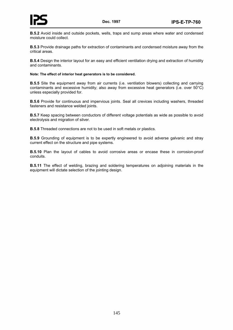
Dec. 1997
IPS-E-TP-760
145
B.5.2 Avoid inside and outside pockets, wells, traps and sump areas where water and condensed moisture could collect.
B.5.3 Provide drainage paths for extraction of contaminants and condensed moisture away from the critical areas.
B.5.4 Design the interior layout for an easy and efficient ventilation drying and extraction of humidity and contaminants.
Note: The effect of interior heat generators is to be considered.
B.5.5 Site the equipment away from air currents (i.e. ventilation blowers) collecting and carrying contaminants and excessive humidity; also away from excessive heat generators (i.e. over 50°C) unless especially provided for.
B.5.6 Provide for continuous and impervious joints. Seal all crevices including washers, threaded fasteners and resistance welded joints.
B.5.7 Keep spacing between conductors of different voltage potentials as wide as possible to avoid electrolysis and migration of silver.
B.5.8 Threaded connections are not to be used in soft metals or plastics.
B.5.9 Grounding of equipment is to be expertly engineered to avoid adverse galvanic and stray current effect on the structure and pipe systems.
B.5.10 Plan the layout of cables to avoid corrosive areas or encase these in corrosion-proof conduits.
B.5.11 The effect of welding, brazing and soldering temperatures on adjoining materials in the equipment will dictate selection of the jointing design.
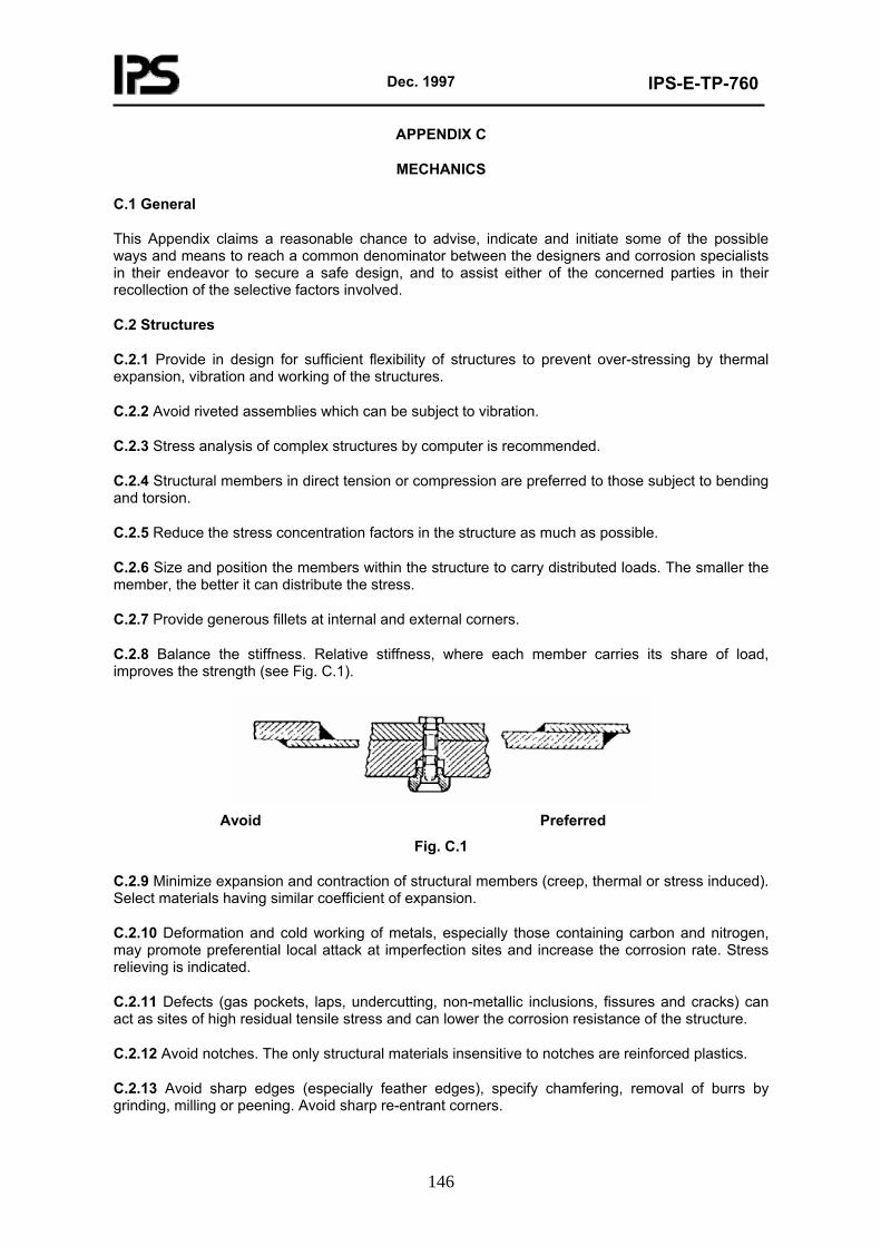
Dec. 1997
IPS-E-TP-760
146
APPENDIX C
MECHANICS
C.1 General
This Appendix claims a reasonable chance to advise, indicate and initiate some of the possible ways and means to reach a common denominator between the designers and corrosion specialists in their endeavor to secure a safe design, and to assist either of the concerned parties in their recollection of the selective factors involved.
C.2 Structures
C.2.1 Provide in design for sufficient flexibility of structures to prevent over-stressing by thermal expansion, vibration and working of the structures.
C.2.2 Avoid riveted assemblies which can be subject to vibration.
C.2.3 Stress analysis of complex structures by computer is recommended.
C.2.4 Structural members in direct tension or compression are preferred to those subject to bending and torsion.
C.2.5 Reduce the stress concentration factors in the structure as much as possible.
C.2.6 Size and position the members within the structure to carry distributed loads. The smaller the member, the better it can distribute the stress.
C.2.7 Provide generous fillets at internal and external corners.
C.2.8 Balance the stiffness. Relative stiffness, where each member carries its share of load, improves the strength (see Fig. C.1).
Avoid Preferred
Fig. C.1
C.2.9 Minimize expansion and contraction of structural members (creep, thermal or stress induced). Select materials having similar coefficient of expansion.
C.2.10 Deformation and cold working of metals, especially those containing carbon and nitrogen, may promote preferential local attack at imperfection sites and increase the corrosion rate. Stress relieving is indicated.
C.2.11 Defects (gas pockets, laps, undercutting, non-metallic inclusions, fissures and cracks) can act as sites of high residual tensile stress and can lower the corrosion resistance of the structure.
C.2.12 Avoid notches. The only structural materials insensitive to notches are reinforced plastics.
C.2.13 Avoid sharp edges (especially feather edges), specify chamfering, removal of burrs by grinding, milling or peening. Avoid sharp re-entrant corners.
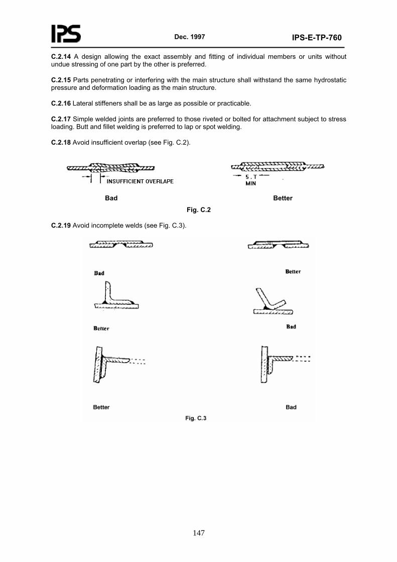
Dec. 1997
IPS-E-TP-760
147
C.2.14 A design allowing the exact assembly and fitting of individual members or units without undue stressing of one part by the other is preferred.
C.2.15 Parts penetrating or interfering with the main structure shall withstand the same hydrostatic pressure and deformation loading as the main structure.
C.2.16 Lateral stiffeners shall be as large as possible or practicable.
C.2.17 Simple welded joints are preferred to those riveted or bolted for attachment subject to stress loading. Butt and fillet welding is preferred to lap or spot welding.
C.2.18 Avoid insufficient overlap (see Fig. C.2).
Bad Better
Fig. C.2
C.2.19 Avoid incomplete welds (see Fig. C.3).
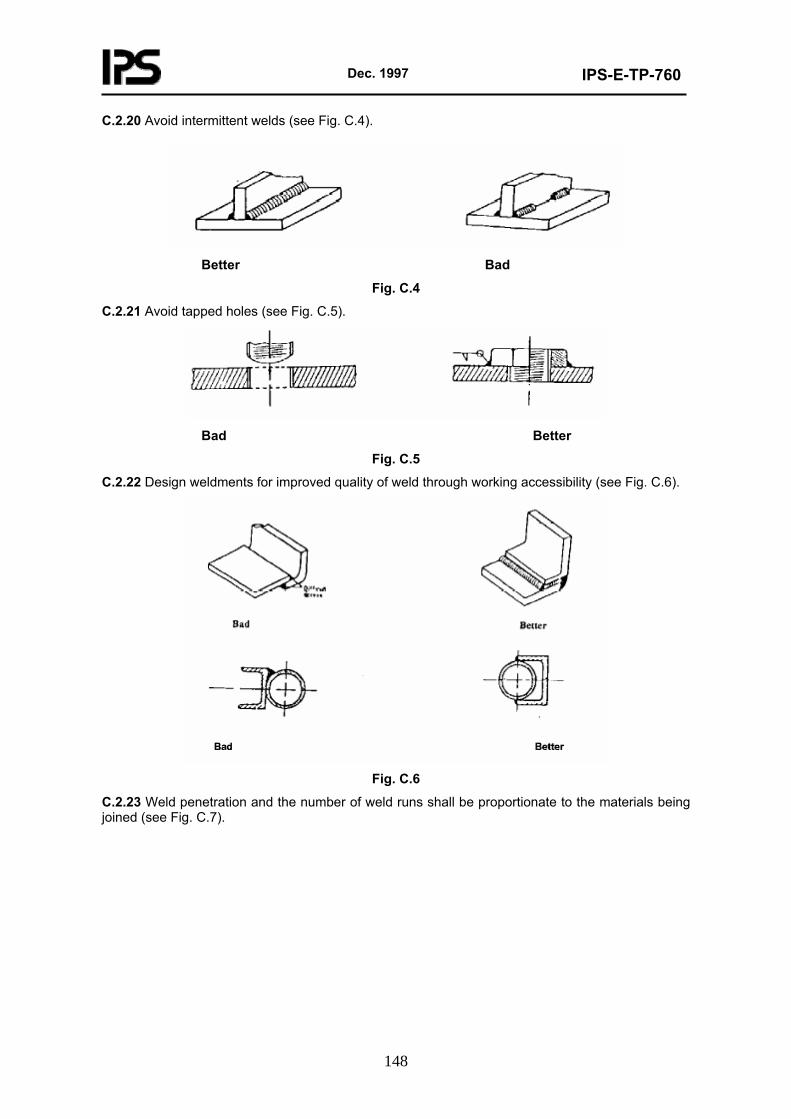
Dec. 1997
IPS-E-TP-760
148
C.2.20 Avoid intermittent welds (see Fig. C.4).
Better Bad
Fig. C.4
C.2.21 Avoid tapped holes (see Fig. C.5).
Bad Better
Fig. C.5
C.2.22 Design weldments for improved quality of weld through working accessibility (see Fig. C.6).
Fig. C.6
C.2.23 Weld penetration and the number of weld runs shall be proportionate to the materials being joined (see Fig. C.7).
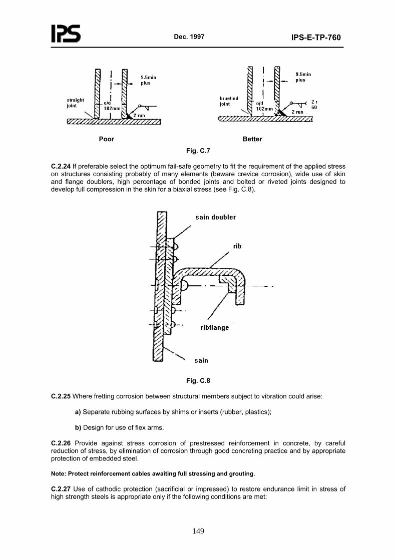
Dec. 1997
IPS-E-TP-760
149
Poor Better
Fig. C.7
C.2.24 If preferable select the optimum fail-safe geometry to fit the requirement of the applied stress on structures consisting probably of many elements (beware crevice corrosion), wide use of skin and flange doublers, high percentage of bonded joints and bolted or riveted joints designed to develop full compression in the skin for a biaxial stress (see Fig. C.8).
Fig. C.8
C.2.25 Where fretting corrosion between structural members subject to vibration could arise:
a) Separate rubbing surfaces by shims or inserts (rubber, plastics);
b) Design for use of flex arms.
C.2.26 Provide against stress corrosion of prestressed reinforcement in concrete, by careful reduction of stress, by elimination of corrosion through good concreting practice and by appropriate protection of embedded steel.
Note: Protect reinforcement cables awaiting full stressing and grouting.
C.2.27 Use of cathodic protection (sacrificial or impressed) to restore endurance limit in stress of high strength steels is appropriate only if the following conditions are met:
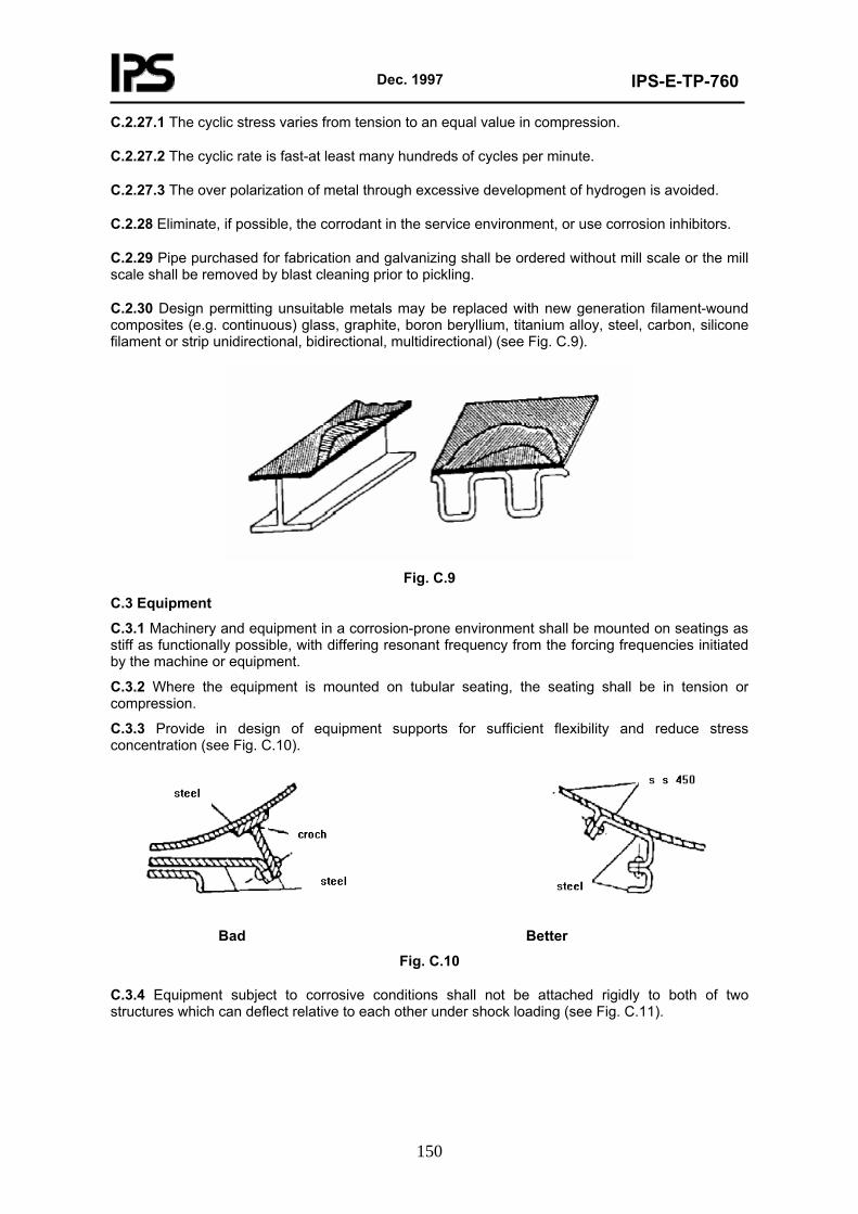
Dec. 1997
IPS-E-TP-760
150
C.2.27.1 The cyclic stress varies from tension to an equal value in compression.
C.2.27.2 The cyclic rate is fast-at least many hundreds of cycles per minute.
C.2.27.3 The over polarization of metal through excessive development of hydrogen is avoided.
C.2.28 Eliminate, if possible, the corrodant in the service environment, or use corrosion inhibitors.
C.2.29 Pipe purchased for fabrication and galvanizing shall be ordered without mill scale or the mill scale shall be removed by blast cleaning prior to pickling.
C.2.30 Design permitting unsuitable metals may be replaced with new generation filament-wound composites (e.g. continuous) glass, graphite, boron beryllium, titanium alloy, steel, carbon, silicone filament or strip unidirectional, bidirectional, multidirectional) (see Fig. C.9).
Fig. C.9
C.3 Equipment
C.3.1 Machinery and equipment in a corrosion-prone environment shall be mounted on seatings as stiff as functionally possible, with differing resonant frequency from the forcing frequencies initiated by the machine or equipment.
C.3.2 Where the equipment is mounted on tubular seating, the seating shall be in tension or compression.
C.3.3 Provide in design of equipment supports for sufficient flexibility and reduce stress concentration (see Fig. C.10).
Bad Better
Fig. C.10
C.3.4 Equipment subject to corrosive conditions shall not be attached rigidly to both of two structures which can deflect relative to each other under shock loading (see Fig. C.11).
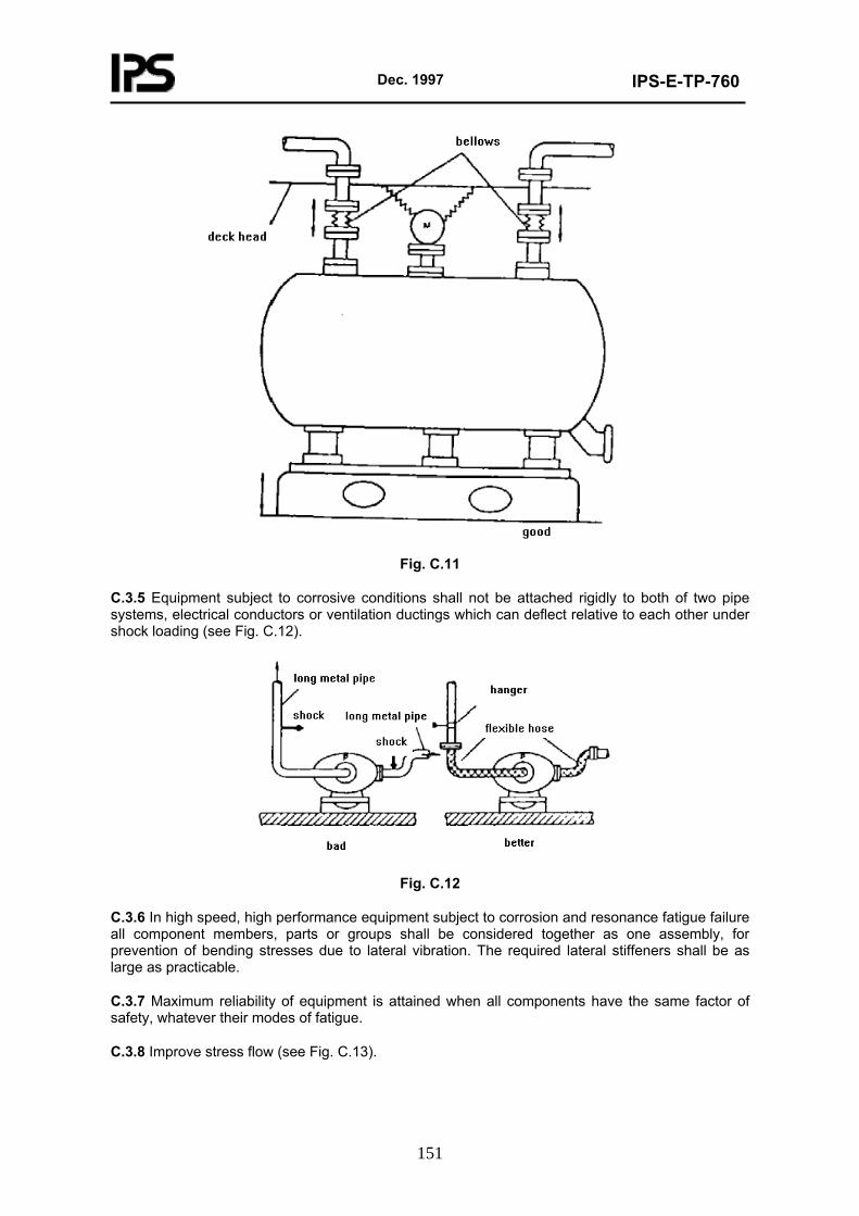
Dec. 1997
IPS-E-TP-760
151
Fig. C.11
C.3.5 Equipment subject to corrosive conditions shall not be attached rigidly to both of two pipe systems, electrical conductors or ventilation ductings which can deflect relative to each other under shock loading (see Fig. C.12).
Fig. C.12
C.3.6 In high speed, high performance equipment subject to corrosion and resonance fatigue failure all component members, parts or groups shall be considered together as one assembly, for prevention of bending stresses due to lateral vibration. The required lateral stiffeners shall be as large as practicable.
C.3.7 Maximum reliability of equipment is attained when all components have the same factor of safety, whatever their modes of fatigue.
C.3.8 Improve stress flow (see Fig. C.13).
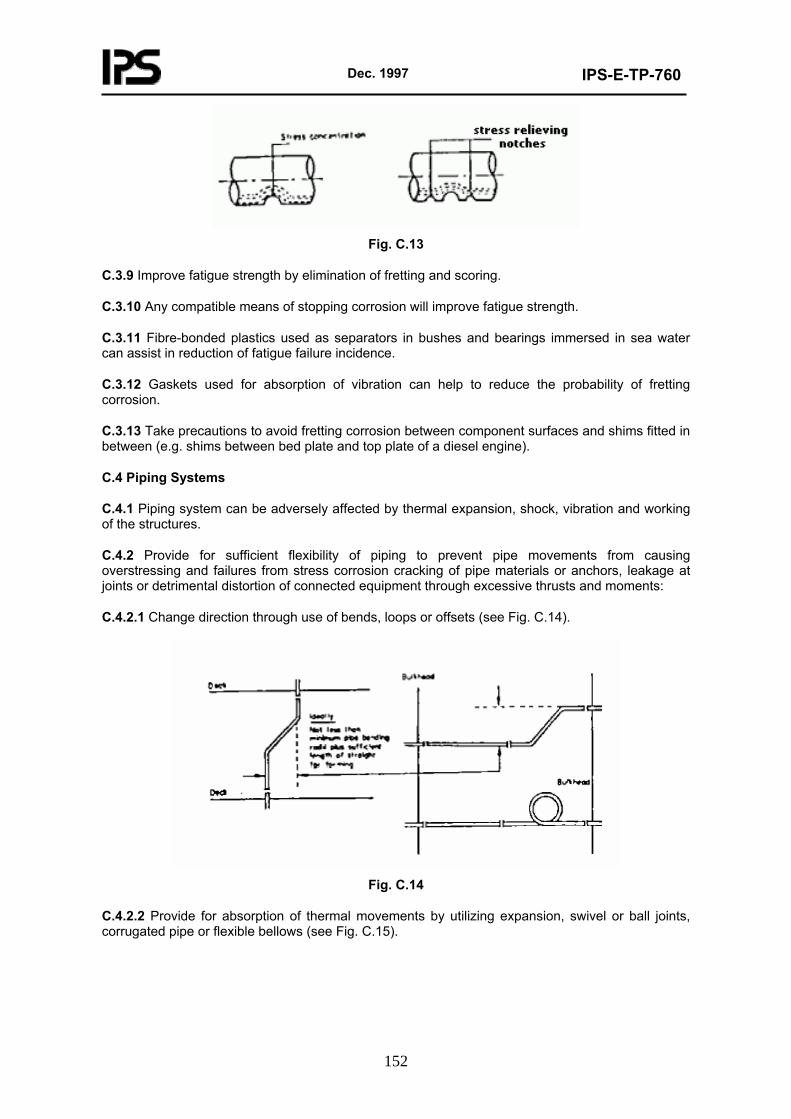
Dec. 1997
IPS-E-TP-760
152
Fig. C.13
C.3.9 Improve fatigue strength by elimination of fretting and scoring.
C.3.10 Any compatible means of stopping corrosion will improve fatigue strength.
C.3.11 Fibre-bonded plastics used as separators in bushes and bearings immersed in sea water can assist in reduction of fatigue failure incidence.
C.3.12 Gaskets used for absorption of vibration can help to reduce the probability of fretting corrosion.
C.3.13 Take precautions to avoid fretting corrosion between component surfaces and shims fitted in between (e.g. shims between bed plate and top plate of a diesel engine).
C.4 Piping Systems
C.4.1 Piping system can be adversely affected by thermal expansion, shock, vibration and working of the structures.
C.4.2 Provide for sufficient flexibility of piping to prevent pipe movements from causing overstressing and failures from stress corrosion cracking of pipe materials or anchors, leakage at joints or detrimental distortion of connected equipment through excessive thrusts and moments:
C.4.2.1 Change direction through use of bends, loops or offsets (see Fig. C.14).
Fig. C.14
C.4.2.2 Provide for absorption of thermal movements by utilizing expansion, swivel or ball joints, corrugated pipe or flexible bellows (see Fig. C.15).
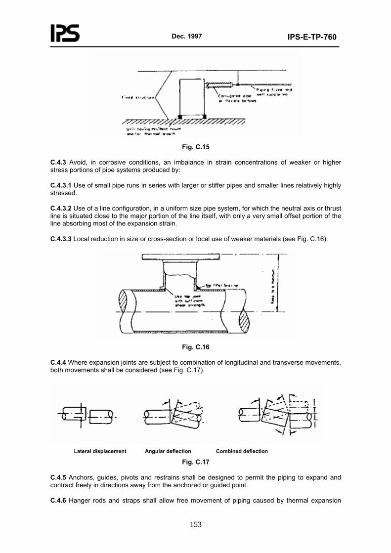
Dec. 1997
IPS-E-TP-760
153
Fig. C.15
C.4.3 Avoid, in corrosive conditions, an imbalance in strain concentrations of weaker or higher stress portions of pipe systems produced by:
C.4.3.1 Use of small pipe runs in series with larger or stiffer pipes and smaller lines relatively highly stressed.
C.4.3.2 Use of a line configuration, in a uniform size pipe system, for which the neutral axis or thrust line is situated close to the major portion of the line itself, with only a very small offset portion of the line absorbing most of the expansion strain.
C.4.3.3 Local reduction in size or cross-section or local use of weaker materials (see Fig. C.16).
Fig. C.16
C.4.4 Where expansion joints are subject to combination of longitudinal and transverse movements, both movements shall be considered (see Fig. C.17).
Lateral displacement Angular deflection Combined deflection
Fig. C.17
C.4.5 Anchors, guides, pivots and restrains shall be designed to permit the piping to expand and contract freely in directions away from the anchored or guided point.
C.4.6 Hanger rods and straps shall allow free movement of piping caused by thermal expansion
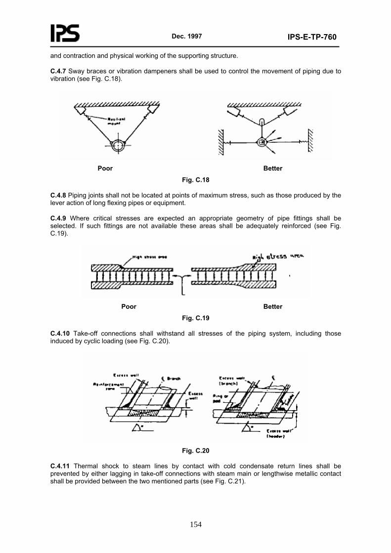
Dec. 1997
IPS-E-TP-760
154
and contraction and physical working of the supporting structure.
C.4.7 Sway braces or vibration dampeners shall be used to control the movement of piping due to vibration (see Fig. C.18).
Poor Better
Fig. C.18
C.4.8 Piping joints shall not be located at points of maximum stress, such as those produced by the lever action of long flexing pipes or equipment.
C.4.9 Where critical stresses are expected an appropriate geometry of pipe fittings shall be selected. If such fittings are not available these areas shall be adequately reinforced (see Fig. C.19).
Poor Better
Fig. C.19
C.4.10 Take-off connections shall withstand all stresses of the piping system, including those induced by cyclic loading (see Fig. C.20).
Fig. C.20
C.4.11 Thermal shock to steam lines by contact with cold condensate return lines shall be prevented by either lagging in take-off connections with steam main or lengthwise metallic contact shall be provided between the two mentioned parts (see Fig. C.21).
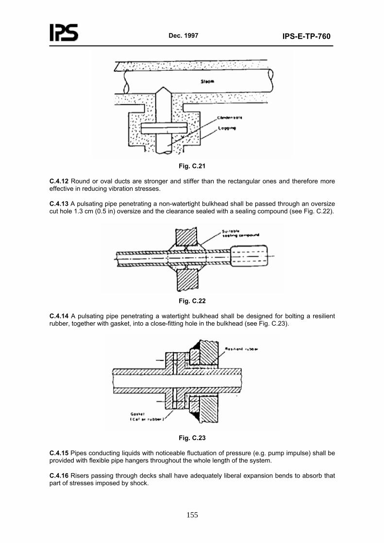
Dec. 1997
IPS-E-TP-760
155
Fig. C.21
C.4.12 Round or oval ducts are stronger and stiffer than the rectangular ones and therefore more effective in reducing vibration stresses.
C.4.13 A pulsating pipe penetrating a non-watertight bulkhead shall be passed through an oversize cut hole 1.3 cm (0.5 in) oversize and the clearance sealed with a sealing compound (see Fig. C.22).
Fig. C.22
C.4.14 A pulsating pipe penetrating a watertight bulkhead shall be designed for bolting a resilient rubber, together with gasket, into a close-fitting hole in the bulkhead (see Fig. C.23).
Fig. C.23
C.4.15 Pipes conducting liquids with noticeable fluctuation of pressure (e.g. pump impulse) shall be provided with flexible pipe hangers throughout the whole length of the system.
C.4.16 Risers passing through decks shall have adequately liberal expansion bends to absorb that part of stresses imposed by shock.
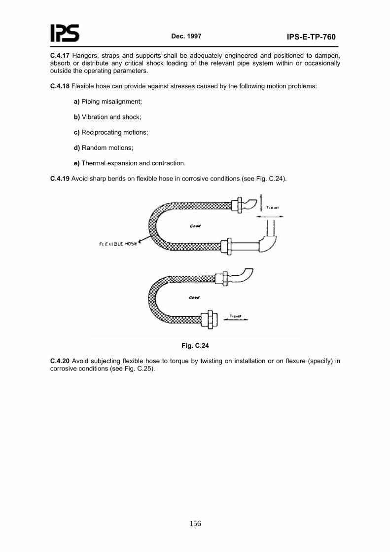
Dec. 1997
IPS-E-TP-760
156
C.4.17 Hangers, straps and supports shall be adequately engineered and positioned to dampen, absorb or distribute any critical shock loading of the relevant pipe system within or occasionally outside the operating parameters.
C.4.18 Flexible hose can provide against stresses caused by the following motion problems:
a) Piping misalignment;
b) Vibration and shock;
c) Reciprocating motions;
d) Random motions;
e) Thermal expansion and contraction.
C.4.19 Avoid sharp bends on flexible hose in corrosive conditions (see Fig. C.24).
Fig. C.24
C.4.20 Avoid subjecting flexible hose to torque by twisting on installation or on flexure (specify) in corrosive conditions (see Fig. C.25).
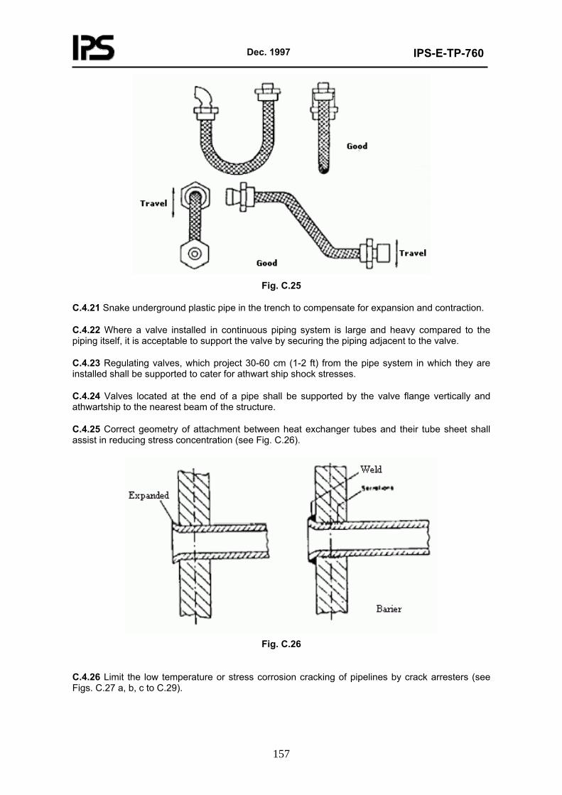
Dec. 1997
IPS-E-TP-760
157
Fig. C.25
C.4.21 Snake underground plastic pipe in the trench to compensate for expansion and contraction.
C.4.22 Where a valve installed in continuous piping system is large and heavy compared to the piping itself, it is acceptable to support the valve by securing the piping adjacent to the valve.
C.4.23 Regulating valves, which project 30-60 cm (1-2 ft) from the pipe system in which they are installed shall be supported to cater for athwart ship shock stresses.
C.4.24 Valves located at the end of a pipe shall be supported by the valve flange vertically and athwartship to the nearest beam of the structure.
C.4.25 Correct geometry of attachment between heat exchanger tubes and their tube sheet shall assist in reducing stress concentration (see Fig. C.26).
Fig. C.26
C.4.26 Limit the low temperature or stress corrosion cracking of pipelines by crack arresters (see Figs. C.27 a, b, c to C.29).
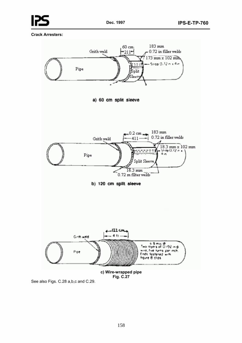
Dec. 1997
IPS-E-TP-760
158
Crack Arresters:
c) Wire-wrapped pipe
Fig. C.27 See also Figs. C.28 a,b,c and C.29.
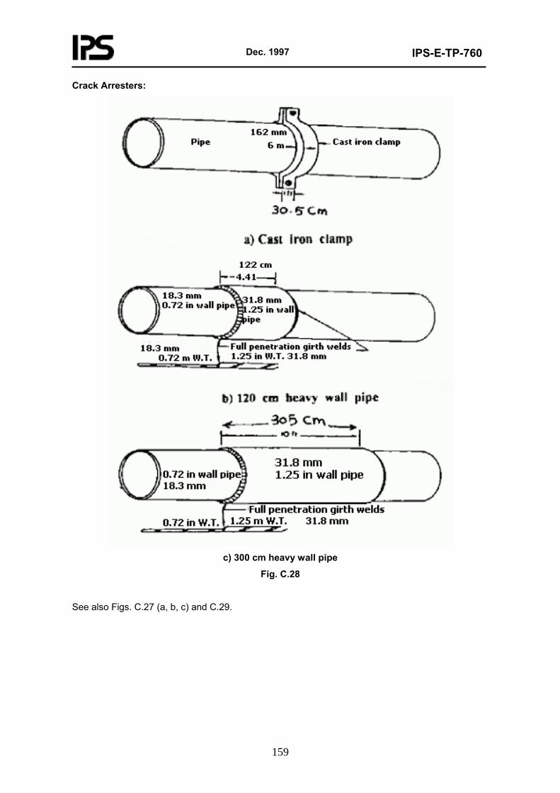
Dec. 1997
IPS-E-TP-760
159
Crack Arresters:
c) 300 cm heavy wall pipe
Fig. C.28
See also Figs. C.27 (a, b, c) and C.29.
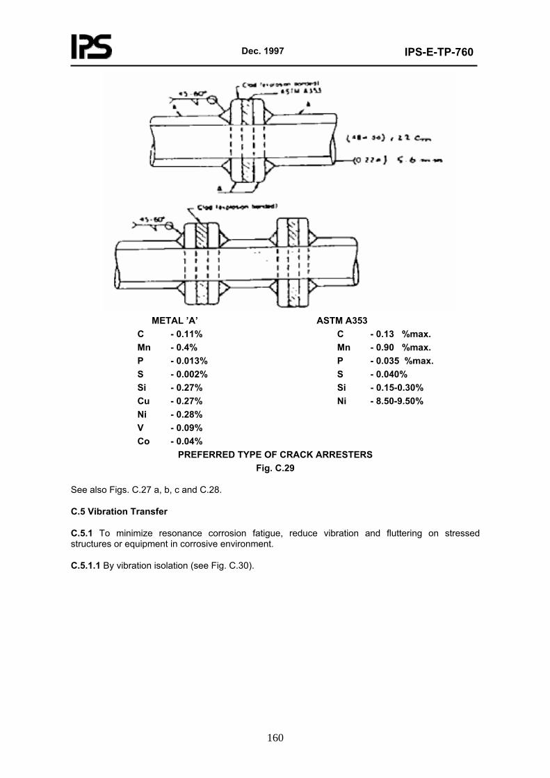
Dec. 1997
IPS-E-TP-760
160
METAL ’A’ ASTM A353
C - 0.11% C - 0.13 %max. Mn - 0.4% Mn - 0.90 %max. P - 0.013% P - 0.035 %max. S - 0.002% S - 0.040% Si - 0.27% Si - 0.15-0.30% Cu - 0.27% Ni - 8.50-9.50% Ni - 0.28% V - 0.09% Co - 0.04%
PREFERRED TYPE OF CRACK ARRESTERS Fig. C.29
See also Figs. C.27 a, b, c and C.28.
C.5 Vibration Transfer
C.5.1 To minimize resonance corrosion fatigue, reduce vibration and fluttering on stressed structures or equipment in corrosive environment.
C.5.1.1 By vibration isolation (see Fig. C.30).
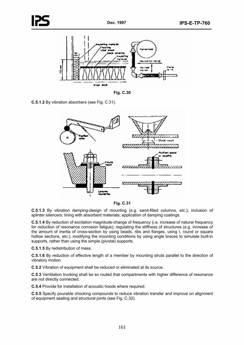
Dec. 1997
IPS-E-TP-760
161
Fig. C.30
C.5.1.2 By vibration absorbers (see Fig. C.31).
Fig. C.31
C.5.1.3 By vibration damping-design of mounting (e.g. sand-filled columns, etc.); inclusion of splinter silencers; lining with absorbent materials; application of damping coatings.
C.5.1.4 By reduction of excitation magnitude-change of frequency (i.e. increase of natural frequency for reduction of resonance corrosion fatigue); regulating the stiffness of structures (e.g. increase of the amount of inertia of cross-section by using beads, ribs and flanges, using I, round or square hollow sections, etc.); modifying the mounting conditions by using angle braces to simulate built-in supports, rather than using the simple (pivotal) supports.
C.5.1.5 By redistribution of mass.
C.5.1.6 By reduction of effective length of a member by mounting struts parallel to the direction of vibratory motion.
C.5.2 Vibration of equipment shall be reduced or eliminated at its source.
C.5.3 Ventilation trunking shall be so routed that compartments with higher difference of resonance are not directly connected.
C.5.4 Provide for installation of acoustic hoods where required.
C.5.5 Specify pourable chocking compounds to reduce vibration transfer and improve on alignment of equipment seating and structural joints (see Fig. C.32).
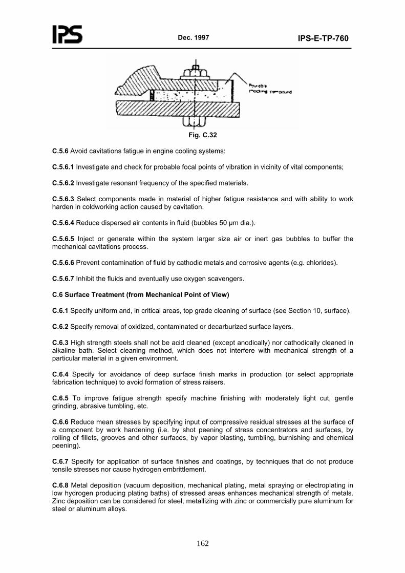
Dec. 1997
IPS-E-TP-760
162
Fig. C.32
C.5.6 Avoid cavitations fatigue in engine cooling systems:
C.5.6.1 Investigate and check for probable focal points of vibration in vicinity of vital components;
C.5.6.2 Investigate resonant frequency of the specified materials.
C.5.6.3 Select components made in material of higher fatigue resistance and with ability to work harden in coldworking action caused by cavitation.
C.5.6.4 Reduce dispersed air contents in fluid (bubbles 50 µm dia.).
C.5.6.5 Inject or generate within the system larger size air or inert gas bubbles to buffer the mechanical cavitations process.
C.5.6.6 Prevent contamination of fluid by cathodic metals and corrosive agents (e.g. chlorides).
C.5.6.7 Inhibit the fluids and eventually use oxygen scavengers.
C.6 Surface Treatment (from Mechanical Point of View)
C.6.1 Specify uniform and, in critical areas, top grade cleaning of surface (see Section 10, surface).
C.6.2 Specify removal of oxidized, contaminated or decarburized surface layers.
C.6.3 High strength steels shall not be acid cleaned (except anodically) nor cathodically cleaned in alkaline bath. Select cleaning method, which does not interfere with mechanical strength of a particular material in a given environment.
C.6.4 Specify for avoidance of deep surface finish marks in production (or select appropriate fabrication technique) to avoid formation of stress raisers.
C.6.5 To improve fatigue strength specify machine finishing with moderately light cut, gentle grinding, abrasive tumbling, etc.
C.6.6 Reduce mean stresses by specifying input of compressive residual stresses at the surface of a component by work hardening (i.e. by shot peening of stress concentrators and surfaces, by rolling of fillets, grooves and other surfaces, by vapor blasting, tumbling, burnishing and chemical peening).
C.6.7 Specify for application of surface finishes and coatings, by techniques that do not produce tensile stresses nor cause hydrogen embrittlement.
C.6.8 Metal deposition (vacuum deposition, mechanical plating, metal spraying or electroplating in low hydrogen producing plating baths) of stressed areas enhances mechanical strength of metals. Zinc deposition can be considered for steel, metallizing with zinc or commercially pure aluminum for steel or aluminum alloys.
Dec. 1997
IPS-E-TP-760
163
C.6.9 Electroplating with tin, cadmium, chromium, nickel or zinc can increase the fatigue strength of metals.
C.6.10 Application of passive films can in some cases reduce the probability of stress corrosion cracking. Conversion coatings may help to protect surfaces against initiation of stress corrosion cracking and eventually reduce the requirement for more costly remedies (annealing, shot peening, etc.).
C.6.11 Suitable increase of the coefficient of friction (e.g. roughening of surface) can reduce occurrence of fretting corrosion.
C.6.12 Use of phosphate coatings (e.g. parkerizing) or porous metallic or inorganic coatings, in conjunction with low viscosity, high tenacity lubricants, can help to reduce fretting corrosion, observing that the lubrication arrangements shall be made accessible and flushing of debris by motion of lubricant facilitated.
C.6.13 Any efficient and compatible painting system applied, where possible, on stressed structures or equipment shall reduce the probability of initiation of stress corrosion cracking or fatigue corrosion. Corrosion shall be prevented in all critically stressed components by all available means, including surface coatings.
C.6.14 Coating the surfaces with organic coatings after case hardening, mechanical work hardening or metallizing brings about improvement in resistance to stress corrosion cracking and in fatigue strength.
C.6.15 Priming with a chromate primer containing not less than 20% zinc chromate shall be specified for all fully heat treated alloys.
C.6.16 The use of metallic, inorganic or organic coatings and linings in steel vessels where hydrogen embritllement can occur is conditionally recommended, provided these vessels (or structures) are not fabricated of high strength steels, the structures are not under high stress loading and the coating does not contain reactive zinc or other metal which under specific environmental conditions could react electrochemically whilst development of gaseous hydrogen takes place.
C.6.17 Steel, clad with austenitic stainless steel or nickel, can also be specified in an environment promoting hydrogen enbrittlement.
C.6.18 Addition of selective inhibitors to the relevant surface environment can reduce the probability of stress corrosion, corrosion fatigue and fretting corrosion; see Section 10 on protection.
C.6.19 The use of wide radii bends in corners of components for hot dip galvanizing is recommended-this minimizes local stress concentration.
C.6.20 Whilst continuous sealed welds are preferred for hot dip galvanized components, whenever these are not practical staggered welding techniques shall be specified to reduce thermal stresses.
C.6.21 The assemblies, which are to be galvanized, shall be preformed accurately to avoid using force to bring them into position.
C.6.22 Welds shall be stress relieved before galvanizing.
C.7 Electrical and Electronic Equipment (from Mechanical Point of View)
C.7.1 Select materials resistant to intergranular corrosion and stress corrosion cracking, where residual and induced stresses could affect the safe function of the equipment.
C.7.2 Where metals are to be bent, formed or shaped, materials which are in an annealed condition shall be used.
Dec. 1997
IPS-E-TP-760
164
C.7.3 Avoid, where necessary, metals subject to hydrogen embrittlement from acid cleaning or plating, or use low hydrogen-producing plating baths.
C.7.4 Specify relieving of embrittlement immediately after plating for a minimum of three hours at 190°C ±14°C.
C.7.5 Specify mechanical stress relieve of parts prior to plating (shot peening).
C.7.6 Specify appropriate preservation with organic coatings, vacuum deposition, mechanical plating, metal spraying or other processes not producing hydrogen; this in preference to electroplating or chemical plating where possible.
C.7.7 Support lighting fixtures on resilient mounts where possible.
C.7.8 Avoid rigid attachment of electrical equipment subject to corrosive conditions which can deflect relative to the conductors, whilst such equipment can vibrate or exposed to shock loading.
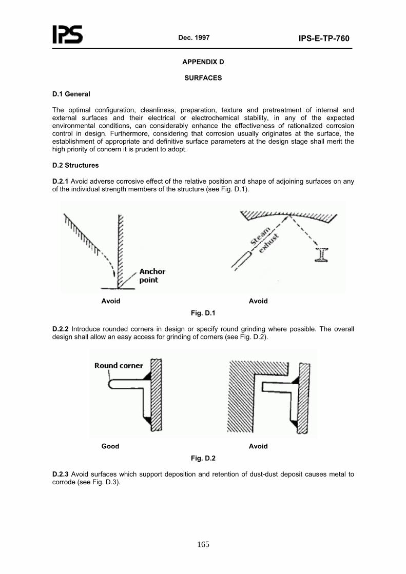
Dec. 1997
IPS-E-TP-760
165
APPENDIX D
SURFACES
D.1 General
The optimal configuration, cleanliness, preparation, texture and pretreatment of internal and external surfaces and their electrical or electrochemical stability, in any of the expected environmental conditions, can considerably enhance the effectiveness of rationalized corrosion control in design. Furthermore, considering that corrosion usually originates at the surface, the establishment of appropriate and definitive surface parameters at the design stage shall merit the high priority of concern it is prudent to adopt.
D.2 Structures
D.2.1 Avoid adverse corrosive effect of the relative position and shape of adjoining surfaces on any of the individual strength members of the structure (see Fig. D.1).
Avoid Avoid
Fig. D.1
D.2.2 Introduce rounded corners in design or specify round grinding where possible. The overall design shall allow an easy access for grinding of corners (see Fig. D.2).
Good Avoid
Fig. D.2
D.2.3 Avoid surfaces which support deposition and retention of dust-dust deposit causes metal to corrode (see Fig. D.3).
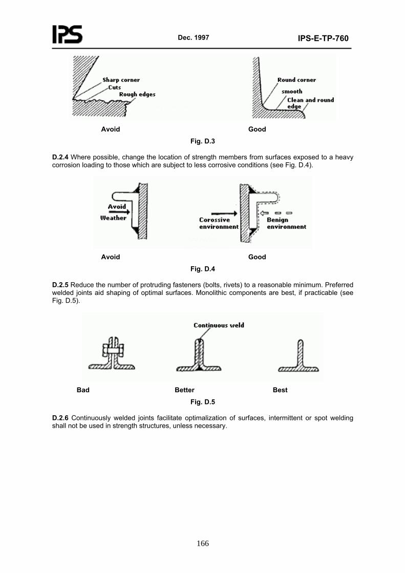
Dec. 1997
IPS-E-TP-760
166
Avoid Good
Fig. D.3
D.2.4 Where possible, change the location of strength members from surfaces exposed to a heavy corrosion loading to those which are subject to less corrosive conditions (see Fig. D.4).
Avoid Good
Fig. D.4
D.2.5 Reduce the number of protruding fasteners (bolts, rivets) to a reasonable minimum. Preferred welded joints aid shaping of optimal surfaces. Monolithic components are best, if practicable (see Fig. D.5).
Bad Better Best
Fig. D.5
D.2.6 Continuously welded joints facilitate optimalization of surfaces, intermittent or spot welding shall not be used in strength structures, unless necessary.
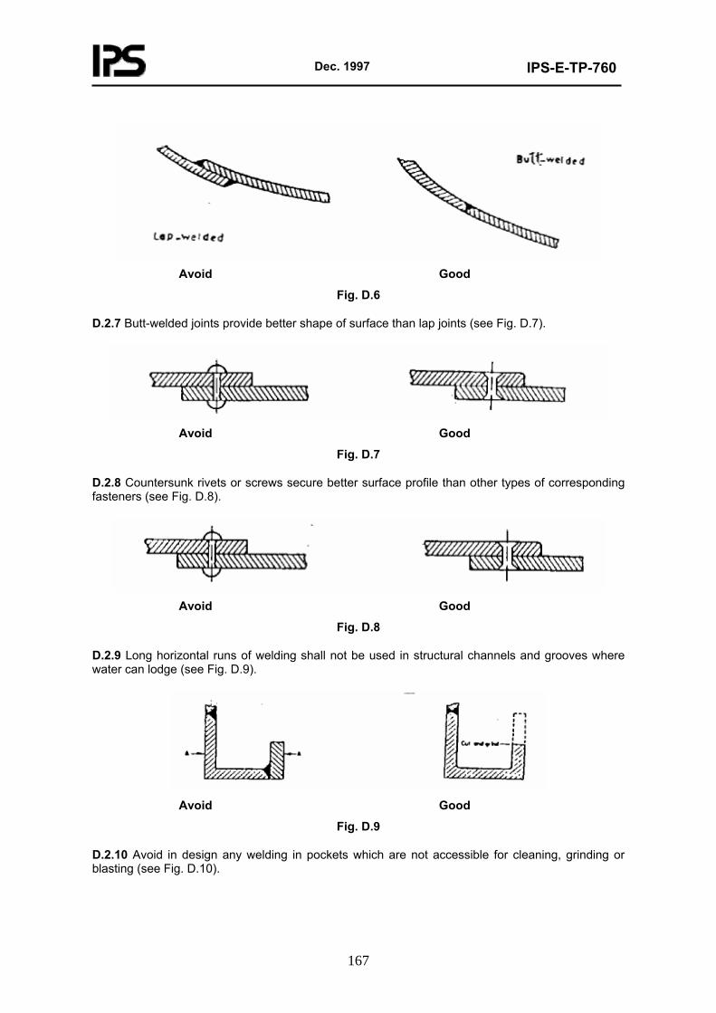
Dec. 1997
IPS-E-TP-760
167
Avoid Good
Fig. D.6
D.2.7 Butt-welded joints provide better shape of surface than lap joints (see Fig. D.7).
Avoid Good
Fig. D.7
D.2.8 Countersunk rivets or screws secure better surface profile than other types of corresponding fasteners (see Fig. D.8).
Avoid Good
Fig. D.8
D.2.9 Long horizontal runs of welding shall not be used in structural channels and grooves where water can lodge (see Fig. D.9).
Avoid Good
Fig. D.9
D.2.10 Avoid in design any welding in pockets which are not accessible for cleaning, grinding or blasting (see Fig. D.10).
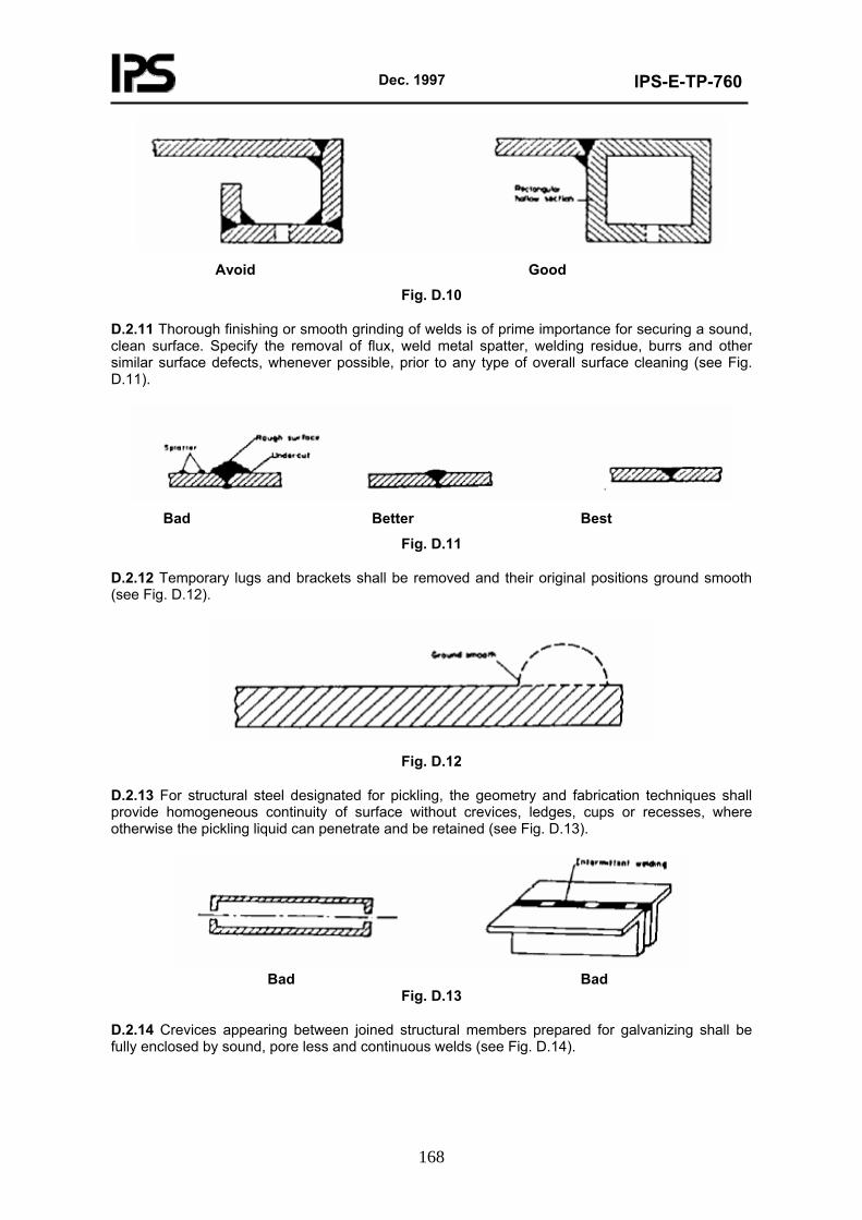
Dec. 1997
IPS-E-TP-760
168
Avoid Good
Fig. D.10
D.2.11 Thorough finishing or smooth grinding of welds is of prime importance for securing a sound, clean surface. Specify the removal of flux, weld metal spatter, welding residue, burrs and other similar surface defects, whenever possible, prior to any type of overall surface cleaning (see Fig. D.11).
Bad Better Best
Fig. D.11
D.2.12 Temporary lugs and brackets shall be removed and their original positions ground smooth (see Fig. D.12).
Fig. D.12
D.2.13 For structural steel designated for pickling, the geometry and fabrication techniques shall provide homogeneous continuity of surface without crevices, ledges, cups or recesses, where otherwise the pickling liquid can penetrate and be retained (see Fig. D.13).
Bad Bad
Fig. D.13
D.2.14 Crevices appearing between joined structural members prepared for galvanizing shall be fully enclosed by sound, pore less and continuous welds (see Fig. D.14).
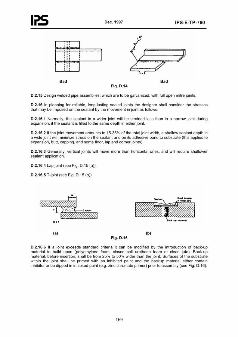
Dec. 1997
IPS-E-TP-760
169
Bad Bad
Fig. D.14
D.2.15 Design welded pipe assemblies, which are to be galvanized, with full open mitre joints.
D.2.16 In planning for reliable, long-lasting sealed joints the designer shall consider the stresses that may be imposed on the sealant by the movement in joint as follows:
D.2.16.1 Normally, the sealant in a wider joint will be strained less than in a narrow joint during expansion, if the sealant is filled to the same depth in either joint.
D.2.16.2 If the joint movement amounts to 15-35% of the total joint width, a shallow sealant depth in a wide joint will minimize stress on the sealant and on its adhesive bond to substrate (this applies to expansion, butt, capping, and some floor, lap and corner joints).
D.2.16.3 Generally, vertical joints will move more than horizontal ones, and will require shallower sealant application.
D.2.16.4 Lap joint (see Fig. D.15 (a)).
D.2.16.5 T-joint (see Fig. D.15 (b)).
(a) (b)
Fig. D.15
D.2.16.6 If a joint exceeds standard criteria it can be modified by the introduction of back-up material to build upon (polyethylene foam, closed cell urethane foam or clean jute). Back-up material, before insertion, shall be from 25% to 50% wider than the joint. Surfaces of the substrate within the joint shall be primed with an inhibited paint and the backup material either contain inhibitor or be dipped in inhibited paint (e.g. zinc chromate primer) prior to assembly (see Fig. D.16).
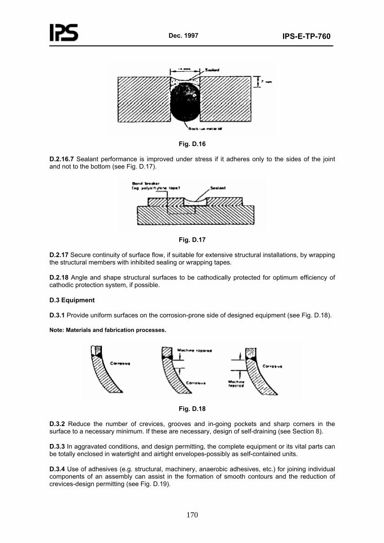
Dec. 1997
IPS-E-TP-760
170
Fig. D.16
D.2.16.7 Sealant performance is improved under stress if it adheres only to the sides of the joint and not to the bottom (see Fig. D.17).
Fig. D.17
D.2.17 Secure continuity of surface flow, if suitable for extensive structural installations, by wrapping the structural members with inhibited sealing or wrapping tapes.
D.2.18 Angle and shape structural surfaces to be cathodically protected for optimum efficiency of cathodic protection system, if possible.
D.3 Equipment
D.3.1 Provide uniform surfaces on the corrosion-prone side of designed equipment (see Fig. D.18).
Note: Materials and fabrication processes.
Fig. D.18
D.3.2 Reduce the number of crevices, grooves and in-going pockets and sharp corners in the surface to a necessary minimum. If these are necessary, design of self-draining (see Section 8).
D.3.3 In aggravated conditions, and design permitting, the complete equipment or its vital parts can be totally enclosed in watertight and airtight envelopes-possibly as self-contained units.
D.3.4 Use of adhesives (e.g. structural, machinery, anaerobic adhesives, etc.) for joining individual components of an assembly can assist in the formation of smooth contours and the reduction of crevices-design permitting (see Fig. D.19).
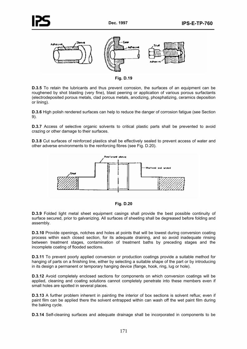
Dec. 1997
IPS-E-TP-760
171
Fig. D.19
D.3.5 To retain the lubricants and thus prevent corrosion, the surfaces of an equipment can be roughened by shot blasting (very fine), blast peening or application of various porous surfactants (electrodeposited porous metals, clad porous metals, anodizing, phosphatizing, ceramics deposition or lining).
D.3.6 High polish rendered surfaces can help to reduce the danger of corrosion fatigue (see Section 9).
D.3.7 Access of selective organic solvents to critical plastic parts shall be prevented to avoid crazing or other damage to their surfaces.
D.3.8 Cut surfaces of reinforced plastics shall be effectively sealed to prevent access of water and other adverse environments to the reinforcing fibres (see Fig. D.20).
Fig. D.20
D.3.9 Folded light metal sheet equipment casings shall provide the best possible continuity of surface secured, prior to galvanizing. All surfaces of sheeting shall be degreased before folding and assembly.
D.3.10 Provide openings, notches and holes at points that will be lowest during conversion coating process within each closed section, for its adequate draining, and so avoid inadequate rinsing between treatment stages, contamination of treatment baths by preceding stages and the incomplete coating of flooded sections.
D.3.11 To prevent poorly applied conversion or production coatings provide a suitable method for hanging of parts on a finishing line, either by selecting a suitable shape of the part or by introducing in its design a permanent or temporary hanging device (flange, hook, ring, lug or hole).
D.3.12 Avoid completely enclosed sections for components on which conversion coatings will be applied, cleaning and coating solutions cannot completely penetrate into these members even if small holes are spotted in several places.
D.3.13 A further problem inherent in painting the interior of box sections is solvent reflux; even if paint film can be applied there the solvent entrapped within can wash off the wet paint film during the baking cycle.
D.3.14 Self-cleaning surfaces and adequate drainage shall be incorporated in components to be
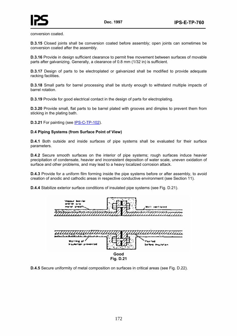
Dec. 1997
IPS-E-TP-760
172
conversion coated.
D.3.15 Closed joints shall be conversion coated before assembly; open joints can sometimes be conversion coated after the assembly.
D.3.16 Provide in design sufficient clearance to permit free movement between surfaces of movable parts after galvanizing. Generally, a clearance of 0.8 mm (1/32 in) is sufficient.
D.3.17 Design of parts to be electroplated or galvanized shall be modified to provide adequate racking facilities.
D.3.18 Small parts for barrel processing shall be sturdy enough to withstand multiple impacts of barrel rotation.
D.3.19 Provide for good electrical contact in the design of parts for electroplating.
D.3.20 Provide small, flat parts to be barrel plated with grooves and dimples to prevent them from sticking in the plating bath.
D.3.21 For painting (see IPS-C-TP-102).
D.4 Piping Systems (from Surface Point of View)
D.4.1 Both outside and inside surfaces of pipe systems shall be evaluated for their surface parameters.
D.4.2 Secure smooth surfaces on the interior of pipe systems; rough surfaces induce heavier precipitation of condensate, heavier and inconsistent deposition of water scale, uneven oxidation of surface and other problems, and may lead to a heavy localized corrosion attack.
D.4.3 Provide for a uniform film forming inside the pipe systems before or after assembly, to avoid creation of anodic and cathodic areas in respective conductive environment (see Section 11).
D.4.4 Stabilize exterior surface conditions of insulated pipe systems (see Fig. D.21).
Good
Fig. D.21
D.4.5 Secure uniformity of metal composition on surfaces in critical areas (see Fig. D.22).
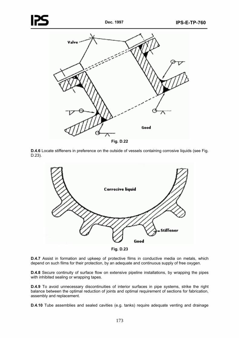
Dec. 1997
IPS-E-TP-760
173
Fig. D.22
D.4.6 Locate stiffeners in preference on the outside of vessels containing corrosive liquids (see Fig. D.23).
Fig. D.23
D.4.7 Assist in formation and upkeep of protective films in conductive media on metals, which depend on such films for their protection, by an adequate and continuous supply of free oxygen.
D.4.8 Secure continuity of surface flow on extensive pipeline installations, by wrapping the pipes with inhibited sealing or wrapping tapes.
D.4.9 To avoid unnecessary discontinuities of interior surfaces in pipe systems, strike the right balance between the optimal reduction of joints and optimal requirement of sections for fabrication, assembly and replacement.
D.4.10 Tube assemblies and sealed cavities (e.g. tanks) require adequate venting and drainage
Dec. 1997
IPS-E-TP-760
174
holes for galvanizing.
D.5 Surface Preparation (see also IPS-C-TP-101)
D.5.1 Surfaces exposed to corrosive conditions shall be protected at all stages of storage, fabrication, assembly and operation-temporary or permanent protective measures can be used.
D.5.2 The texture of surfaces (surface finish) has considerable influence not only on the mechanical performance of the component, reduction of friction and control of wear but also on the extension of its economic life obtained through the efficiency of the relevant corrosion-control precautions. This applies whether the materials remain uncoated or any further finish be applied.
D.5.3 The principal parameters in securing proper surface finish control are as follows:
a) Machining or application cost control;
b) Friction reduction;
c) Wear control;
d) Lubrication control;
e) Durability;
f) Holding of tolerances;
g) Precise fittings;
h) Resistance to initiation of corrosion;
i) Economic permanency of corrosion control;
j) Application of protective coatings;
k) Final appearance;
l) Consistency of operation;
m) Reduction of vibration.
D.5.4 Where a film of lubricant must be maintained between two moving parts (bearings, journals, cylinder bores, piston pins, bushings, pad bearings, helical and worm gears, seal surfaces, machine ways, etc.), the surface irregularities must be small enough to avoid penetrating the oil film under the most severe operating conditions but not too small to bring loss of lubricity in cases where boundary lubrication exists or where surfaces are not compatible (e.g. surfaces are too hard).
D.5.5 Smoothness and lack of waviness are essential on high precision pieces for accuracy and pressure-retaining ability (injectors, high pressure cylinders, micrometer anvils, gages and gage blocks).
D.5.6 Smooth surfaces bring elimination of sharp irregularities which are the greatest potential source of fatigue cracks on highly stressed members subjected to load reversals (see Section 9).
D.5.7 Smoothness of final appearance can also be controlled by production tools (rolls, extrusion dies, precisioncasting dies).
D.5.8 Surface finish control of such parts as gears may be necessary to secure quiet operation and to reduce vibration (see Section 5).
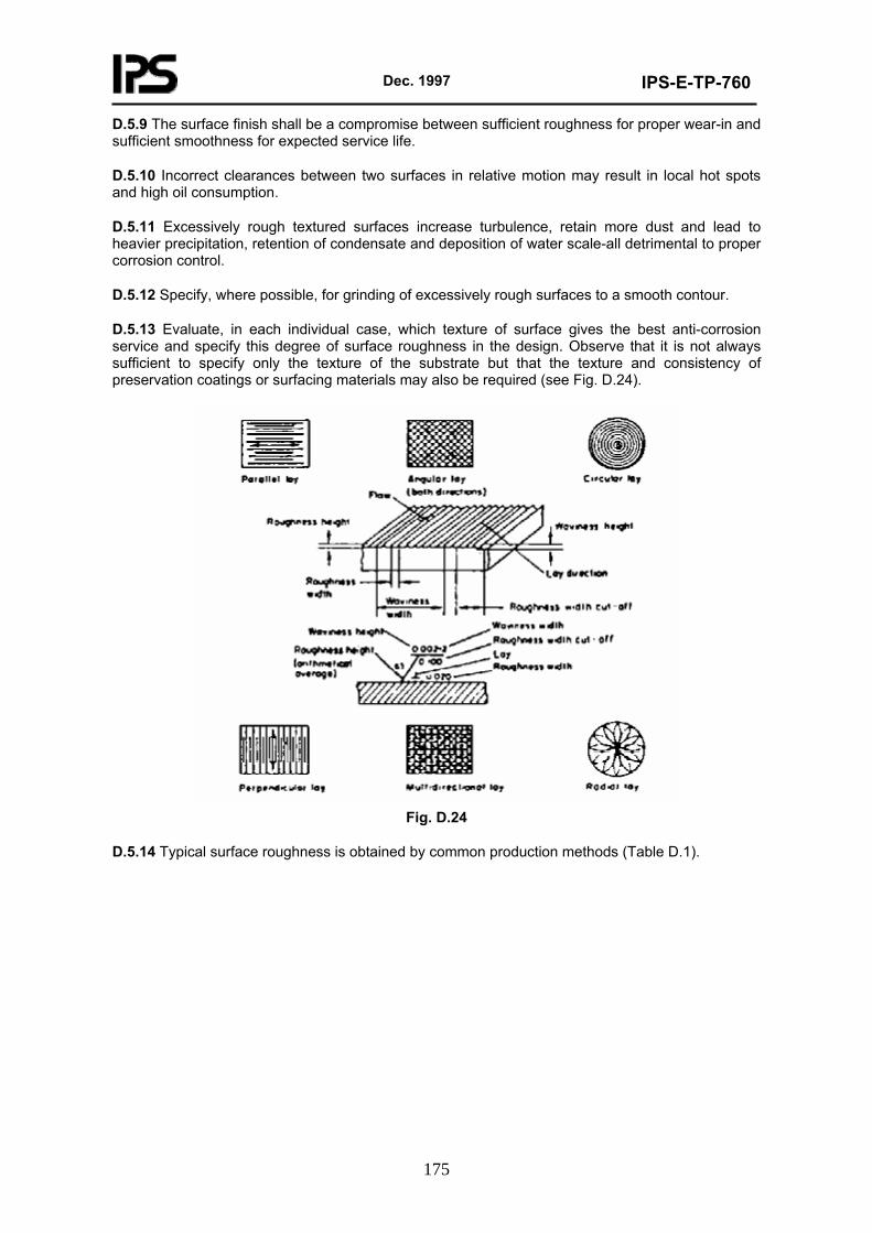
Dec. 1997
IPS-E-TP-760
175
D.5.9 The surface finish shall be a compromise between sufficient roughness for proper wear-in and sufficient smoothness for expected service life.
D.5.10 Incorrect clearances between two surfaces in relative motion may result in local hot spots and high oil consumption.
D.5.11 Excessively rough textured surfaces increase turbulence, retain more dust and lead to heavier precipitation, retention of condensate and deposition of water scale-all detrimental to proper corrosion control.
D.5.12 Specify, where possible, for grinding of excessively rough surfaces to a smooth contour.
D.5.13 Evaluate, in each individual case, which texture of surface gives the best anti-corrosion service and specify this degree of surface roughness in the design. Observe that it is not always sufficient to specify only the texture of the substrate but that the texture and consistency of preservation coatings or surfacing materials may also be required (see Fig. D.24).
Fig. D.24
D.5.14 Typical surface roughness is obtained by common production methods (Table D.1).
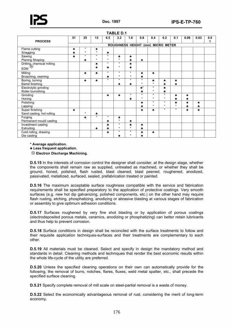
Dec. 1997
IPS-E-TP-760
176
TABLE D.1 51 25 13 6.5 3.2 1.6 0.8 0.4 0.2 0.1 0.06 0.03 0.0
1
PROCESS ROUGHNESS HEIGHT (mm) MICRO METER
Flame cutting Snagging
♣ ♣
* *
♣ *
♣
Sawing Planing Shaping
♣ * ♣
* *
* *
♣ *
♣ ♣
♣
Drilling, chemical milling EDM ⊕
♣ ♣
* ♣
* *
♣ ♣
Milling Broaching, reaming
♣ ♣ * ♣
* *
* *
♣ ♣
♣
Boring, turning Barrel finishing
♣ ♣ * * ♣
* ♣
* *
♣ *
♣ ♣
♣ ♣
Electrolytic grinding Roller burnishing
♣* ♣
* *
♣ ♣
Grinding Honing
♣ ♣ * ♣
* *
* *
* *
♣ ♣
♣ ♣
Polishing Lapping
♣ ♣
* *
* *
♣ *
♣ ♣
♣ ♣
Super finishing Sand casting, hot rolling
♣ *
♣
♣ ♣ * * ♣ ♣
Forging Permanent mould casting
♣ * * ♣
♣ *
♣
Investment casting Extruding
♣
♣ ♣
* *
♣ *
♣ ♣
Cold rolling, drawing Die casting
♣ * ♣
* *
♣ ♣
♣
* Average application. ♣ Less frequent application. ⊕ Electron Discharge Machining.
D.5.15 In the interests of corrosion control the designer shall consider, at the design stage, whether the components shall remain raw as supplied, untreated as machined, or whether they shall be ground, honed, polished, flash rusted, blast cleaned, blast peened, roughened, anodized, passivated, metallized, surfaced, sealed, prefabrication treated or painted.
D.5.16 The maximum acceptable surface roughness compatible with the service and fabrication requirements shall be specified preparatory to the application of protective coatings. Very smooth surfaces (e.g. new hot dip galvanizing, polished components, etc.) on the other hand may require flash rusting, etching, phosphatizing, anodizing or abrasive blasting at various stages of fabrication or assembly to give optimum adhesion conditions.
D.5.17 Surfaces roughened by very fine shot blasting or by application of porous coatings (electrodeposited porous metals, ceramics, anodizing or phosphatizing) can better retain lubricants and thus help to prevent corrosion.
D.5.18 Surface conditions in design shall be reconciled with the surface treatments to follow and their requisite application techniques-surfaces and their treatments are complementary to each other.
D.5.19 All materials must be cleaned. Select and specify in design the mandatory method and standards in detail. Cleaning methods and techniques that render the best economic results within the whole life-cycle of the utility are preferred.
D.5.20 Unless the specified cleaning operations on their own can automatically provide for the following, the removal of burrs, notches, flares, fluxes, weld metal spatter, etc., shall precede the specified surface cleaning.
D.5.21 Specify complete removal of mill scale on steel-partial removal is a waste of money.
D.5.22 Select the economically advantageous removal of rust, considering the merit of long-term economy.
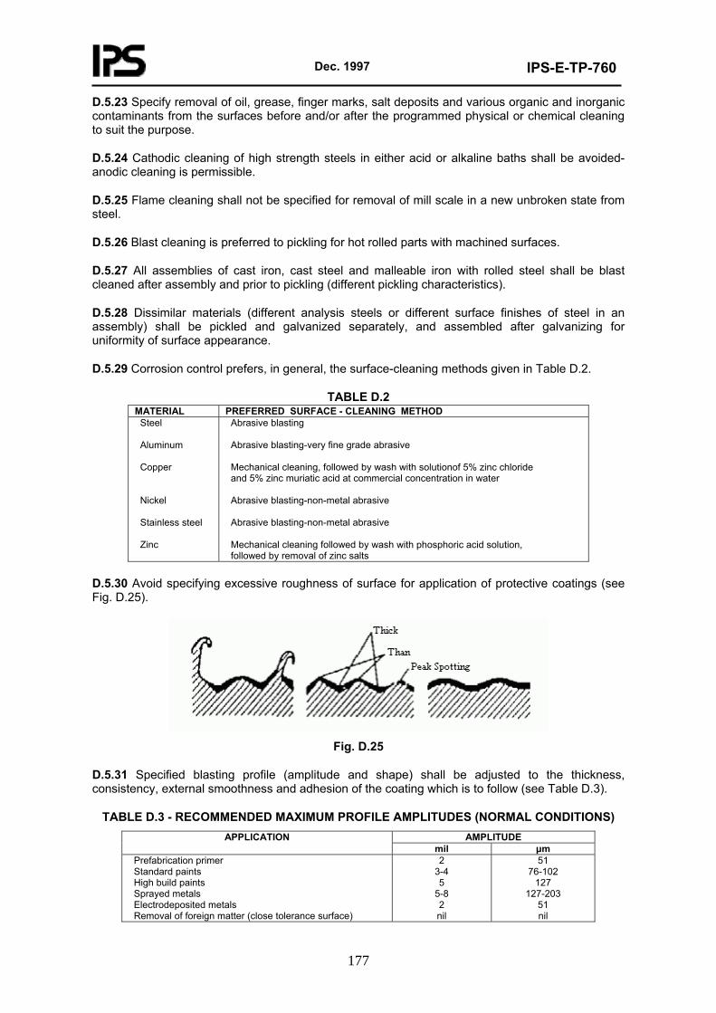
Dec. 1997
IPS-E-TP-760
177
D.5.23 Specify removal of oil, grease, finger marks, salt deposits and various organic and inorganic contaminants from the surfaces before and/or after the programmed physical or chemical cleaning
of high strength steels in either acid or alkaline baths shall be avoided-anodic cleaning is permissible.
be specified for removal of mill scale in a new unbroken state from steel.
Blast cleaning is preferred to pickling for hot rolled parts with machined surfaces.
ll be blast cleaned after assembly and prior to pickling (different pickling characteristics).
ishes of steel in an assembly) shall be pickled and galvanized separately, and assembled after galvanizing for
general, the surface-cleaning methods given in Table D.2.
MATERIAL PREFERRED SURFACE - CLEANING METHOD
to suit the purpose.
D.5.24 Cathodic cleaning
D.5.25 Flame cleaning shall not
D.5.26
D.5.27 All assemblies of cast iron, cast steel and malleable iron with rolled steel sha
D.5.28 Dissimilar materials (different analysis steels or different surface fin
uniformity of surface appearance.
D.5.29 Corrosion control prefers, in
TABLE D.2
Steel
s steel
Abrasive blasting
solutionof 5% zinc chloride ncentration in water
with phosphoric acid solution,
num Alumi
Copper Nickel Stainles Zinc
very fine grade abrasive Abrasive blasting-
Mechanical cleaning, followed by wash with and 5% zinc muriatic acid at commercial co
Abrasive blasting-non-metal abrasive Abrasive blasting-non-metal abrasive Mechanical cleaning followed by wash followed by removal of zinc salts
D.5.30 Avoid specifying face for application of protective coatings (see Fig. D.25).
excessive roughness of sur
Fig. D.25
D.5.31 Specified blasting profile (amplitud pe) shall be adjusted to the thickness, consistency, external smoothness and adhesion of the coating which is to follow (see Table D.3).
e and sha
TABLE D.3 - RECOMMENDED MAXIMUM PROFILE AMPLITUDES (NORMAL CONDITIONS)AMPLITUDE APPLICATION
mil μm Prefabrication primer Standard paints
etals matter (close tolerance surface)
2 51 76-102
High build paints Sprayed metals Electrodeposited m Removal of foreign
3-4 5
5-8 2 nil
1 27127-203
51 nil
Dec. 1997
IPS-E-TP-760
178
D.5.32 ning and hard surfacing of metals shall be luated for a p substantial aggrav
nd surfaces, potting compounds, rubber linings and metal-filled surfaces)
alvanized or painted with zinc-rich paints or embossed.
ble.
ious, otherwise they shall be sealed.
ded fasteners, epoxy or silicone
e specified for use only on surfaces which have been treated previously
es, spatter, oxidation and rough areas.
ing water and drying prior to application of an
g with such metals as gold, rhodium and platinum, which are nce of maximum
Surface harde eva ossible ation of corrosion.
D.5.33 Specify, if required, suitable surfacing materials (metals, ceramics, mastics, deck covering underlays, cements, fillers, noise damping and anti-condensation compounds, plastic and reinforced plastic linings afor protection of relevant surfaces (e.g. against cavitations on propellers, cylinder liners, pumps, impellers, etc.) and for build-up of surfaces to uniform level, optimum surface profile (e.g. for drain ability, improvement of contour and fairing and for improvement of appearance), or for fill-in of spaces which cannot be otherwise preserved. Degree of surface roughness of surfactants shall also be indicated.
D.5.34 Prefabrication treatment of steel shall provide for adequate protection on storage, fabrication and assembly until such time as the final coatings can be applied (approximately 6-9 months).
D.5.35 Pipe purchased for fabrication and galvanizing shall be ordered without mill scale or the mill scale shall be removed by blast cleaning prior to pickling.
D.5.36 Pipe fittings for galvanizing shall be of uncoated steel.
D.5.37 Markings and lettering applied to surfaces to be gshall be made in water-soluble colors or otherwise be punched
D.6 Electrical and Electronic Equipment
D.6.1 Specify and design for smooth surfaces without crevices, as far as practica
D.6.2 Joints shall be continuous and imperv
D.6.3 Crevices, especially those in stainless steel (i.e. joints, under washers, at threaetc.), shall be sealed with suitable sealants (e.g. polysulphide, polyurethane, rubber) or petroleum jelly.
D.6.4 Non-hydroscopic insulation should be used.
D.6.5 Marker tapes shall bwith varnish.
D.6.6 Proper, thorough and compatible cleaning methods shall be specified before joining, coating, potting, impregnation and encapsulation of components.
D.6.7 Flux residues shall be removed after brazing and soldering.
D.6.8 Welds shall be cleaned, after welding, of scale, flux
D.6.9 Fingermarks shall either be prevented or removed.
D.6.10 Surface contaminants shall be removed from conductor surfaces by an appropriate cleanmethod. This shall be followed by priming with de-ionizedorganic moisture barrier for protection.
D.6.11 No aggressive cleaning methods shall be used on printed circuit boards.
D.6.12 The use of solid metals or platininherently resistant to tarnishing, shall be specified to ensure maintenaconductivity.
D.6.13 Electromagnetic compatibility of electrically bonded metals shall be secured by the selected surface finish (see Table D.4).
Dec. 1997
IPS-E-TP-760
179
TABLE D.4 METAL SURFACE FINISH
Aluminum (all other alloys)
Iron and steel
corrosion-resistant steels
Tin-lead (solder) plate or tinplate preferred Cadmium hemical film treatment. Low electr
. Gold plate
te
use of adherent oxide film
Aluminum 1100, 3003 and clad alloys Bare of chromate-type film treatment Low electrical resistance
Copper, copper alloys Cadmium Magnesium Nickel and Silver Solder Tin
plate chromate-type cical resistance
Bare, Tinplate or tin lead (solder) plate preferred Cadmium plate Bare or chromate treated
r) plate preferred. Cadmium pla Tinplate or tin lead (solde Bare. Clean immediately before and coat joint immediately after bonding Bare. Difficult to bond beca Bare Bare Bare
D.6.14 Avoid using exposed soft s joints, prior to electroplating.
Resistance welded joints shall be sealed.
older at
D.6.15
Dec. 1997
IPS-E-TP-760
180
APPENDIX E
PROTECTION
E.1 General
To decide on the required, necessary and economically feasible protection the personnel engaged in this task have a vast variety of protective measures, systems, methods, techniques and especially competitive products to choose from. Extensive engineering investigation, independent suitability testing and practical proof of effectiveness may be needed to precede the final choice.
The designer should seek enlightenment on the preselected specialties from dedicated and, if possible, independent specialists-in fact, co-operation is a necessity for a designer engaged in creative design. The designer, who is not a corrosion specialist, cannot acquire an encyclopedic knowledge of all relevant disciplines.
For these reasons, and to allow the designer the intelligent insight necessary for the formulation of his design policy, only an outline of procedures is recorded in this Appendix, the details being left to the correctly reasoned effort of all interested parties co-operating in the design team and the specialized information in hand.
E.2 Protection of Structures
E.2.1 Anodic metallic coatings have proved their economic value for the protection of capital structures (galvanized, metallized, zinc-rich paints).
E.2.2 Where, however, the use of metallic coatings is contemplated for protection of strength structures, attention shall be given to the problems of ageing, cracking, diffusion, corrosion and hydrogen embrittlement (this one due both to the methods of preparation of surface and the development of gaseous hydrogen by the cathodic protection process).
E.2.3 Metallic coatings used under insulation shall always be well sealed and protected.
E.2.4 Zinc coatings have a good corrosion resistance in most neutral environments, especially if passivated. Zinc coatings without sealer shall not be used in corrosive conditions (marine and industrial environments), in totally unventilated spaces and in proximity of electronic equipment subject to phenolic vapors emanating from insulating materials, varnishes or encapsulates.
E.2.5 Average thickness of zinc sprayed on structural steel is normally 76 µm (3 mils); in corrosive conditions up to 153 µm (6 mils) thickness is used. Average weight of zinc applied by galvanizing on structural steel is 61 mg/cm2 (2 oz/ft2) surface.
E.2.6 Aluminum coatings (99.5% commercial purity aluminum) have a good corrosion resistance to marine conditions, industrial atmospheres, weak acids, etc.; layer corrosion of heat treated aluminum can be completely stopped by hot sprayed aluminum coating (main impurity must not be copper) of its surfaces. Coupling of so-protected structures to copper, lead or other noble metals is not normally recommended.
E.2.7 Average thickness of hot sprayed aluminum on structural metals (steel, aluminum) is normally 102 µm (4 mils); for immersed conditions up to 203 µm (8 mils) of aluminum spray can be specified.
E.2.8 All provisions must be made in design for application of a uniform thickness of protective metallic coatings (see Section 10).
E.2.9 Cadmium metallic coating is superior to zinc coating in stain and tarnish resistance in rural environments. In marine conditions its resistance is uncertain. Chromate post-treatment shall be used. Cadmium coating shall not be used in totally unventilated spaces and in proximity of electronic equipment subject to phenolic vapors emanating from insulating materials, varnishes or
Dec. 1997
IPS-E-TP-760
181
encapsulates.
E.2.10 Lead coatings have good corrosion resistance to sulphuric acid and to industrial atmospheres without chlorides or nitrates.
E.2.11 Cathodic metallic coatings shall not be used on submerged and underground structures subject to physical damage and abrasion.
E.2.12 Areas of structural metals affected by cavitations can be surfaced by welding wire or strip, or overlay welding, or coating with dense high-tensile materials that resist damage of cavitations (e.g. chromium stainless steel 18-8).
E.2.13 Thermal-sprayed coatings are not homogeneous isotropic entities, and they do not have the same properties as identical bulk materials.
E.2.13.1 Passage through flame or arc causes preferential oxidation.
E.2.13.2 Contaminants are picked up.
E.2.13.3 Strength is lost and coating may become embrittled.
E.2.13.4 Reaction to heat treatment changes.
E.2.13.5 Thermal conductivity changes.
E.2.13.6 Porosity of coating influences fracture behavior.
E.2.13.7 Bond adherence varies.
E.2.14 Perform detailed analysis of local environmental conditions prior to undertaking activities appertaining to selection of protective systems, see Fig. E.1.
Fig. E.1
Dec. 1997
IPS-E-TP-760
182
E.2.15 Weathering, etching, hot phosphating or priming with calcium plum bate shall be specified prior to application of sealer or paint on top of galvanizing.
E.2.16 Appropriate cleaning, etching or priming with zinc chromate primer or barrier coat shall be specified prior to application of sealer or paint on top of hot sprayed metal or zinc-rich primer.
E.2.17 Due consideration shall be given to any adverse effect of the coating on the substrate of metal or metallic coating (e.g. lead-or copper-containing compounds shall not be applied on top of solid or coating zinc or aluminum). This applies also to application over zinc-rich primers.
E.2.18 Prefabrication treatment of structural metals, critical strength permitting, is recommended. Fabrication procedures must be fitting to the use of prefabrication-treated metals.
E.2.19 To facilitate application and inspection select individual and different colors or tinting of successive coats within a paint system.
E.2.20 High duty paints and compositions shall be specified for protection from corrosive fluids, in less accessible spaces and for protection of the cathodic metal in a galvanic couple.
E.2.21 Post-assembly and post-painting flame cutting and welding shall be reduced to a minimum. Specify restoration of damaged coatings to their original integrity.
E.2.22 Provide against any unnecessary damage to coatings applied at the preassembly stage.
E.2.23 Aluminum or aluminum coatings shall not be anodized if electrical conductivity is required.
E.2.24 Fully heat treated aluminum alloys, prior to painting, shall be primed with chromate primer containing not less than 20% zinc chromate pigment.
E.2.25 Comprehensive and technically accurate coating specifications shall be an inherent part of all structural designs; reference to relevant IPS standards of coatings and painting and application methods is to be made (see IPS-E-TP-100 and IPS-E-TP-270).
E.2.26 Instructions for expert inspection of protective coatings shall be given for the particular design; this throughout the application of the whole system, operation after operation; reference is made to IPS-C-TP-102 and IPS-C-TP-274.
E.2.27 Cathodic protection dielectric shields shall have good insulating qualities, low permeability, good adhesion and good alkaline resistance. The shields shall be of sufficient size to prevent damage to the adjacent coating system and ensure good current distribution. It is recommended to increase the coating thickness of the adjacent paint coating in the immediate periphery of the shield.
E.2.28 The limit on polarization level below 1 V negative (Ag/AgCl) is valid for marine coatings, including zinc primers used together with cathodic protection systems.
E.2.29 Environmental anti-pollution regulations and health precautions shall be incorporated into specifications and design:
a) cleaning of materials-in-shop cleaning, vacublast, wet blasting;
b) supply of raw materials (paints, solvents)-non-toxic or reduced toxic contents.
E.2.30 Design parameters for selection of coatings of hydrodynamic structures are as follows:
E.2.30.1 Frictional resistance (relative speed, wetted surface area, surface roughness).
E.2.30.2 Wave and eddy resistance (from total resistance obtained by tests in hydrodynamic tanks subtract frictional resistance).
Dec. 1997
IPS-E-TP-760
183
E.2.31 Concrete structures lying in waterlogged ground shall be protected with sealing membranes (e.g. a high build bituminous composition on top of primer).
E.2.32 Piles and structures to be enveloped or jacketed shall first be cleaned and freed of all contamination and fouling. Surfaces to be jacketed shall also be by preference and, if possible, primed with anti-corrosion composition prior to jacketing (see also Sections 7, 10 and Fig. E.2).
Fig. E.2
E.2.33 Prior to application of corrosion inhibiting or insulating wrapping tapes to structural steel, the steel shall be thoroughly cleaned and primed. Tubular structures shall be wrapped as described in 11.7. Structural shapes shall be taped longitudinally. The tape shall be well pressed down and smooth, and the tension shall not be excessive. Folds and air pockets shall be avoided; the tape over protruding nuts, bolts, etc., shall be cut in the form of cross, with the tape pressed firmly to the metal and the exposed surface patched up with a piece of tape (see Fig. E.3).
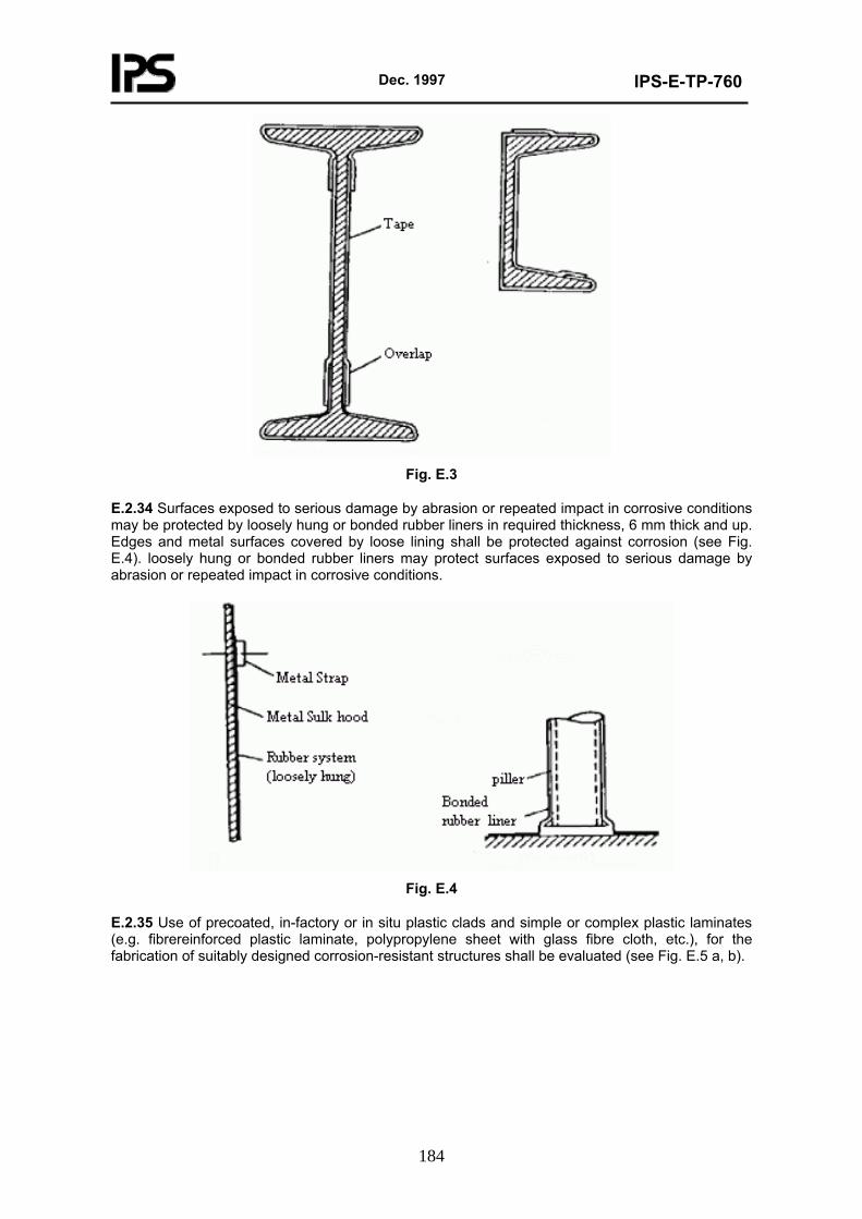
Dec. 1997
IPS-E-TP-760
184
Fig. E.3
E.2.34 Surfaces exposed to serious damage by abrasion or repeated impact in corrosive conditions may be protected by loosely hung or bonded rubber liners in required thickness, 6 mm thick and up. Edges and metal surfaces covered by loose lining shall be protected against corrosion (see Fig. E.4). loosely hung or bonded rubber liners may protect surfaces exposed to serious damage by abrasion or repeated impact in corrosive conditions.
Fig. E.4
E.2.35 Use of precoated, in-factory or in situ plastic clads and simple or complex plastic laminates (e.g. fibrereinforced plastic laminate, polypropylene sheet with glass fibre cloth, etc.), for the fabrication of suitably designed corrosion-resistant structures shall be evaluated (see Fig. E.5 a, b).
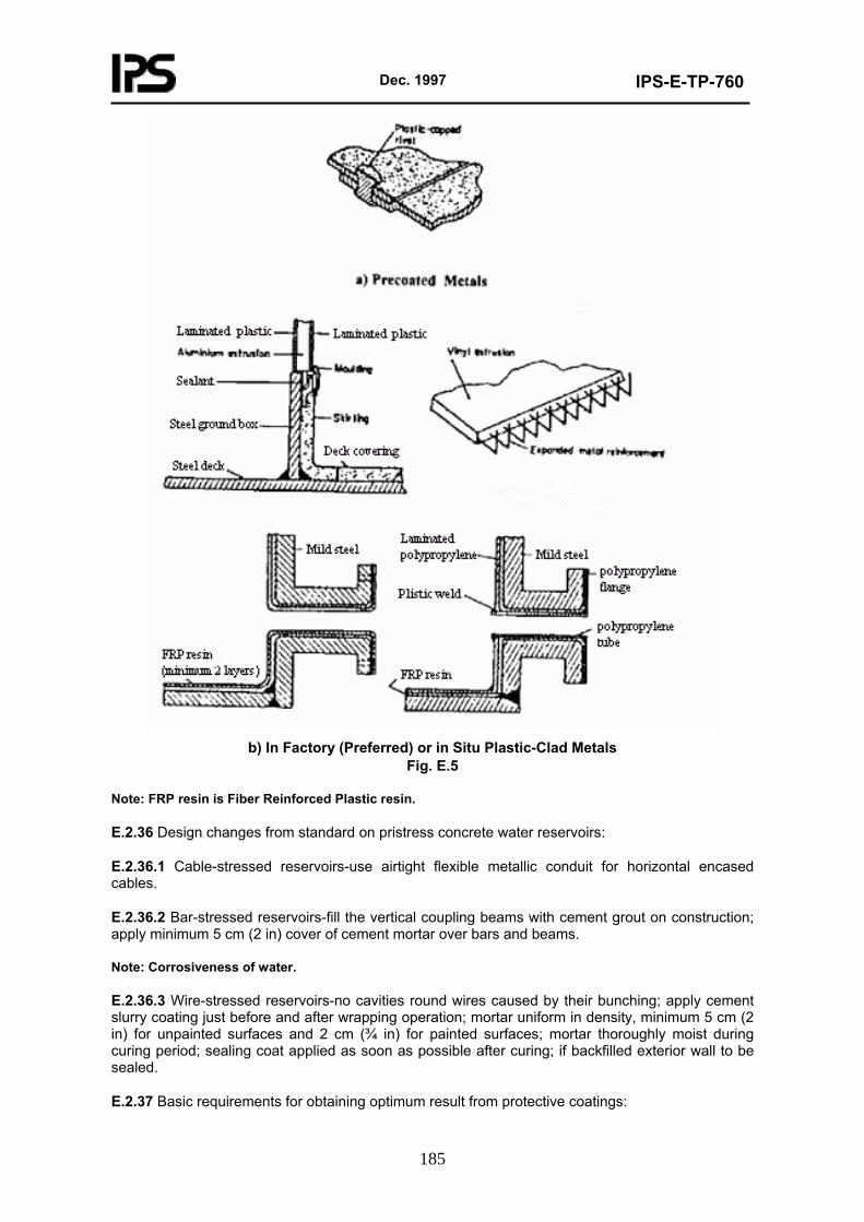
Dec. 1997
IPS-E-TP-760
185
b) In Factory (Preferred) or in Situ Plastic-Clad Metals
Fig. E.5
Note: FRP resin is Fiber Reinforced Plastic resin.
E.2.36 Design changes from standard on pristress concrete water reservoirs:
E.2.36.1 Cable-stressed reservoirs-use airtight flexible metallic conduit for horizontal encased cables.
E.2.36.2 Bar-stressed reservoirs-fill the vertical coupling beams with cement grout on construction; apply minimum 5 cm (2 in) cover of cement mortar over bars and beams.
Note: Corrosiveness of water.
E.2.36.3 Wire-stressed reservoirs-no cavities round wires caused by their bunching; apply cement slurry coating just before and after wrapping operation; mortar uniform in density, minimum 5 cm (2 in) for unpainted surfaces and 2 cm (¾ in) for painted surfaces; mortar thoroughly moist during curing period; sealing coat applied as soon as possible after curing; if backfilled exterior wall to be sealed.
E.2.37 Basic requirements for obtaining optimum result from protective coatings:
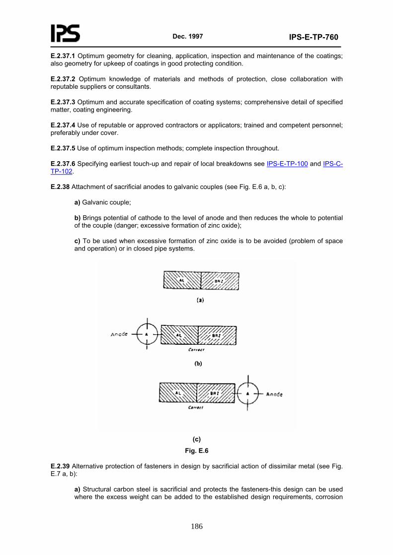
Dec. 1997
IPS-E-TP-760
186
E.2.37.1 Optimum geometry for cleaning, application, inspection and maintenance of the coatings; also geometry for upkeep of coatings in good protecting condition.
E.2.37.2 Optimum knowledge of materials and methods of protection, close collaboration with reputable suppliers or consultants.
E.2.37.3 Optimum and accurate specification of coating systems; comprehensive detail of specified matter, coating engineering.
E.2.37.4 Use of reputable or approved contractors or applicators; trained and competent personnel; preferably under cover.
E.2.37.5 Use of optimum inspection methods; complete inspection throughout.
E.2.37.6 Specifying earliest touch-up and repair of local breakdowns see IPS-E-TP-100 and IPS-C-TP-102.
E.2.38 Attachment of sacrificial anodes to galvanic couples (see Fig. E.6 a, b, c):
a) Galvanic couple;
b) Brings potential of cathode to the level of anode and then reduces the whole to potential of the couple (danger; excessive formation of zinc oxide);
c) To be used when excessive formation of zinc oxide is to be avoided (problem of space and operation) or in closed pipe systems.
(c)
Fig. E.6
E.2.39 Alternative protection of fasteners in design by sacrificial action of dissimilar metal (see Fig. E.7 a, b):
a) Structural carbon steel is sacrificial and protects the fasteners-this design can be used where the excess weight can be added to the established design requirements, corrosion
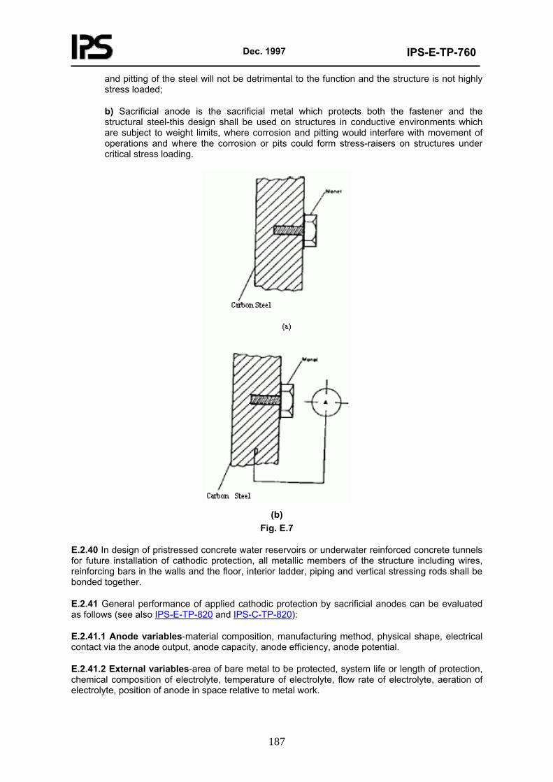
Dec. 1997
IPS-E-TP-760
187
and pitting of the steel will not be detrimental to the function and the structure is not highly stress loaded;
b) Sacrificial anode is the sacrificial metal which protects both the fastener and the structural steel-this design shall be used on structures in conductive environments which are subject to weight limits, where corrosion and pitting would interfere with movement of operations and where the corrosion or pits could form stress-raisers on structures under critical stress loading.
(b)
Fig. E.7
E.2.40 In design of pristressed concrete water reservoirs or underwater reinforced concrete tunnels for future installation of cathodic protection, all metallic members of the structure including wires, reinforcing bars in the walls and the floor, interior ladder, piping and vertical stressing rods shall be bonded together.
E.2.41 General performance of applied cathodic protection by sacrificial anodes can be evaluated as follows (see also IPS-E-TP-820 and IPS-C-TP-820):
E.2.41.1 Anode variables-material composition, manufacturing method, physical shape, electrical contact via the anode output, anode capacity, anode efficiency, anode potential.
E.2.41.2 External variables-area of bare metal to be protected, system life or length of protection, chemical composition of electrolyte, temperature of electrolyte, flow rate of electrolyte, aeration of electrolyte, position of anode in space relative to metal work.
Dec. 1997
IPS-E-TP-760
188
E.2.41.3 Design variables-area of metal work to be protected, type of coating, length and frequency of time the metal work is in contact with electrolyte, required life of system, selected current density.
E.2.42 Centrally located anode is twice as efficient as one mounted at one end of structure. Two symmetrically located anodes are about 1.6 times as effective as a single anode. Where more anodes are used the efficiency increases and total current requirement is reduced.
E.2.43 Avoid using too few high output anodes; relatively poor distribution efficiency increases the requirement of current (applies to sacrificial anode and impressed current systems).
E.2.44 Avoid locating anodes in groups close together.
E.2.45 Provide for electrical continuity of all metallic components, in immersed structures, that are cathodically protected.
E.2.46 Avoid over-protection of cathodically protected structures; this could cause peeling of protective paint systems and also hydrogen embrittlement, especially of high strength steels.
E.2.47 Combination of coating and cathodic protection is required for effective protection of submerged structures.
E.2.48 Bare inorganic zinc coatings shall not be used together with the cathodic protection systems in submerged conditions (sea or brackish water). This applies also to painting of bilges protected with sacrificial anodes (see E.2.4).
E.2.49 Sacrificial pieces shall be used on critical structures subject to a heavy corrosion loading, even when the whole structure is protected by cathodic protection overall.
E.2.50 Trailing anodes provide an advantage of uniform potential field distribution.
For typical arrangement of the cathodic protection in different structures (see IPS-C-TP-820 and Fig. E.8).
E.2.51 To prevent galvanic corrosion of bimetallic structures the concentration of inhibitor shall be increased as compared with protection of a single metal structure.
E.3 Protection of Equipment
E.3.1 Where good corrosion resistance is required nickel coatings can be used for protection, particularly in chloride free atmospheres and in highly alkaline conditions. Use of chromium over nickel improves appearance and corrosion resistance.
E.3.2 Chemical-resistant compositions of glass can be used as a coating of air-heater element plates, tank heating coils, air-heater tubing, economizer tubing, economizers, etc.
E.3.3 Avoid specifying and designing for dry working surfaces of exposed fittings (e.g. door clips)-specify suitable lubrication.
E.3.4 Parts which are totally and continuously immersed in oil or grease (preferably inhibited), and those embedded in encapsulate or moisture proof compound, need not necessarily be given any further protection. Local application of oil or grease, however, does not automatically provide good corrosion protection.
E.3.5 Dip-coating in suitable plastics may be used for submerged mild steel equipment exposed to high pressures and relatively low temperatures.
E.3.6 Use of precoated and plastic-clad metals may be considered for production of equipment cabinets.
Dec. 1997
IPS-E-TP-760
189
E.3.7 When impingement of surfaces by vapor bubbles or erosion by abrasion action is possible, a lining of surfaces with loose or bonded elastomers may be considered (see Fig. E.8). The surfaces of equipment to be so treated must be clean, smooth and preferably inhibited or coated with anti-corrosion coatings. The thickness of lining depends upon flow and impact energy. Screwed joints shall be avoided (see IPS-E-TP-350).
Fig. E.8
E.3.8 Tanks to contain corrosive liquids may be overall or partially lined with bonded or independent flexible laminated plastic liners (see Fig. E.9). Ingress of corrosive liquids to the interface between the elastomer liner and the metal must be prevented (see IPS-E-TP-350 and IPS-C-TP-352).
Fig. E.9
E.3.9 Under optimal conditions some surface coatings can serve several purposes, i.e. corrosion prevention, electrical neutrality and chemical inertness, self-cleaning and lubricity. Balanced evaluation for the particular design is necessary.
E.3.10 Use of coatings and linings for absorption or attenuation of noise shall be considered.
E.3.11 Cathodically protected equipment shall not be over-protected; over-protection may cause peeling of paint and hydrogen embrittlement of high strength steels.
Dec. 1997
IPS-E-TP-760
190
E.3.12 Both painting and cathodic protection are mostly required for protection of submerged equipment.
E.3.13 Critical equipment shall be protected locally by sacrificial pieces where exposed to heavy corrosion loading.
E.3.14 Cathodic protection of condenser boxes and other heat exchangers using natural waters is a necessity (see Fig. E.10).
Fig. E.10
E.3.15 Cathodic protection of inhibited recirculating cooling water systems (copper tubes, steel tubesheet) can be effective if:
E.3.15.1 Sodium-zinc molecularly dehydrated glassy phosphate inhibitor is used.
E.3.15.2 Overhang of the copper tubes in the sheet is below 6 mm (¼ in) for 19 mm (¾ in) diameter tubes on 25 mm (1 in) centers.
E.3.15.3 Magnesium anodes located 30 cm (12 in) from tubesheets are used and their shape is optimal.
E.3.16 Provide for admittance of sufficient air to the flowing fluid to relieve the local or general low pressure areas and so eliminate the cause of cavitation.
E.3.17 Provide feed water treatment on cooling towers or evaporative condensers by disposable chemical cartridges where suitable or by other means.
E.3.18 Provide for intake of unpolluted air into internal combustion engines, gas turbines and boilers. Demisters, filters, chemical filters, preheaters or air dryers may be required to remove adverse solid, liquid or gaseous pollutants.
E.3.19 Provide for supply of clean and unpolluted lubricants and propulsion fuels to propulsion machinery and other plant. Filters, coalescer-filters, etc., may be necessary to remove solid, liquid or gaseous pollutants.
For typical arrangement of anodic and cathodic protection of equipment see IPS-C-TP-820.
E.4 Protection of Pipe System (see IPS-E-TP-270)
E.4.1 Metallic coatings can be used not only for protection but also for simplification of surfaces,
Dec. 1997
IPS-E-TP-760
191
electrical or thermal conductivity, avoidance of crevices etc. (see Fig. E.11).
Fig. E.11
E.4.2 Selection of buried pipelines coatings is based on the following requirements:
E.4.2.1 Highest insulating resistance over the entire operating service life.
E.4.2.2 Resistance to deformation stresses along the weight-bearing surfaces.
E.4.2.3 Resistance to temperature (high and low) deformation forces.
E.4.2.4 Chemical inertness to water-soluble electrolytes.
E.4.2.5 Insolubility in petroleum crudes, derivatives and solvents.
E.4.2.6 Resistance to microbiological attack.
E.4.2.7 Optimum economy.
E.4.2.8 Easy maintainability.
E.4.3 Residual stresses input in pipe weldments by fabrication processes are aggravated by hot dip galvanizing.
E.4.4 Pipes up to a 5 cm (2 in) bore can be lined, normally in lengths up to 3 m (10 ft), with rubber where required; larger bores can be lined in lengths up to 6 m (20 ft) (see Fig. E.12). Standard flanged-bolted type pipe work can be used for rubber lining; screwed joints are generally not satisfactory. Elbows, bends and tees can also be lined. Normally the substrate surfaces should be clean, metallized or primed prior to application of rubber lining.
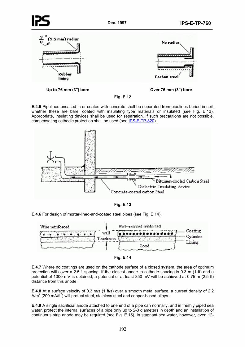
Dec. 1997
IPS-E-TP-760
192
Up to 76 mm (3") bore Over 76 mm (3") bore
Fig. E.12
E.4.5 Pipelines encased in or coated with concrete shall be separated from pipelines buried in soil, whether these are bare, coated with insulating type materials or insulated (see Fig. E.13). Appropriate, insulating devices shall be used for separation. If such precautions are not possible, compensating cathodic protection shall be used (see IPS-E-TP-820).
Fig. E.13
E.4.6 For design of mortar-lined-and-coated steel pipes (see Fig. E.14).
Fig. E.14
E.4.7 Where no coatings are used on the cathode surface of a closed system, the area of optimum protection will cover a 2.5:1 spacing. If the closest anode to cathode spacing is 0.3 m (1 ft) and a potential of 1000 mV is obtained, a potential of at least 850 mV will be achieved at 0.75 m (2.5 ft) distance from this anode.
E.4.8 At a surface velocity of 0.3 m/s (1 ft/s) over a smooth metal surface, a current density of 2.2 A/m2 (200 mA/ft2) will protect steel, stainless steel and copper-based alloys.
E.4.9 A single sacrificial anode attached to one end of a pipe can normally, and in freshly piped sea water, protect the internal surfaces of a pipe only up to 2-3 diameters in depth and an installation of continuous strip anode may be required (see Fig. E.15). In stagnant sea water, however, even 12-
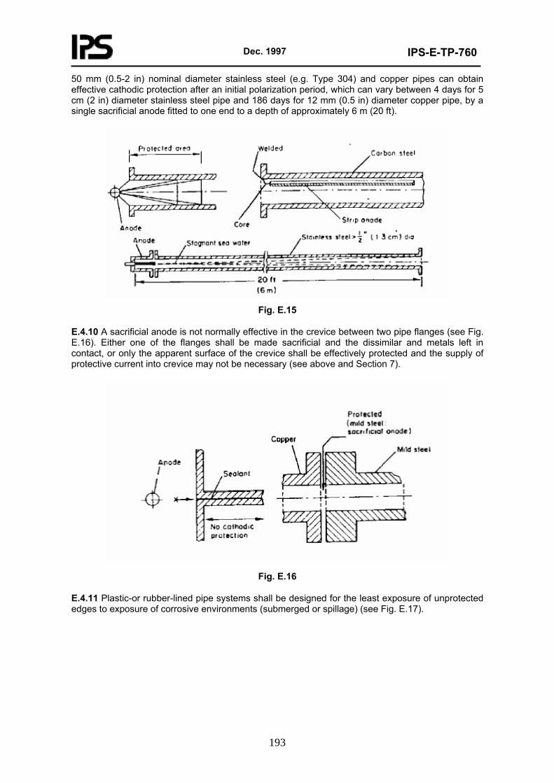
Dec. 1997
IPS-E-TP-760
193
50 mm (0.5-2 in) nominal diameter stainless steel (e.g. Type 304) and copper pipes can obtain effective cathodic protection after an initial polarization period, which can vary between 4 days for 5 cm (2 in) diameter stainless steel pipe and 186 days for 12 mm (0.5 in) diameter copper pipe, by a single sacrificial anode fitted to one end to a depth of approximately 6 m (20 ft).
Fig. E.15
E.4.10 A sacrificial anode is not normally effective in the crevice between two pipe flanges (see Fig. E.16). Either one of the flanges shall be made sacrificial and the dissimilar and metals left in contact, or only the apparent surface of the crevice shall be effectively protected and the supply of protective current into crevice may not be necessary (see above and Section 7).
Fig. E.16
E.4.11 Plastic-or rubber-lined pipe systems shall be designed for the least exposure of unprotected edges to exposure of corrosive environments (submerged or spillage) (see Fig. E.17).
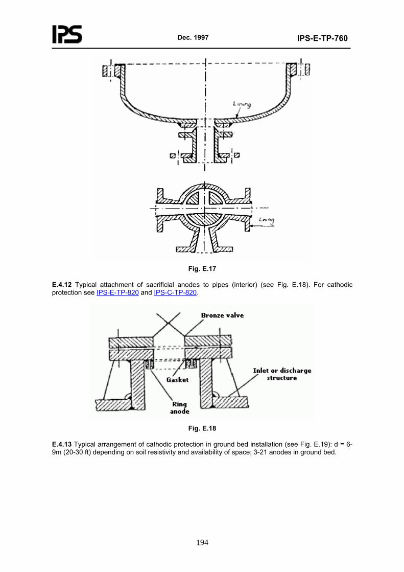
Dec. 1997
IPS-E-TP-760
194
Fig. E.17
E.4.12 Typical attachment of sacrificial anodes to pipes (interior) (see Fig. E.18). For cathodic protection see IPS-E-TP-820 and IPS-C-TP-820.
Fig. E.18
E.4.13 Typical arrangement of cathodic protection in ground bed installation (see Fig. E.19): d = 6-9m (20-30 ft) depending on soil resistivity and availability of space; 3-21 anodes in ground bed.
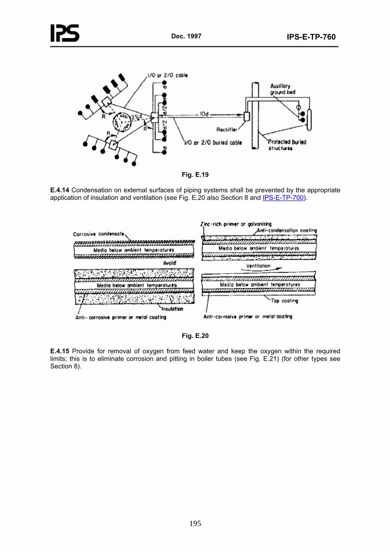
Dec. 1997
IPS-E-TP-760
195
Fig. E.19
E.4.14 Condensation on external surfaces of piping systems shall be prevented by the appropriate application of insulation and ventilation (see Fig. E.20 also Section 8 and IPS-E-TP-700).
Fig. E.20
E.4.15 Provide for removal of oxygen from feed water and keep the oxygen within the required limits; this is to eliminate corrosion and pitting in boiler tubes (see Fig. E.21) (for other types see Section 8).
Dec. 1997
IPS-E-TP-760
196
Fig. E.21
E.4.16 Where a differential of temperatures could affect the corrosivity of environment or cause adverse stresses in materials, provision for adjustment of the temperature of the transported liquid shall be made.
E.4.17 Where liquid is being transported through pipes made of active/passive metals, a natural or forced oxygenation of liquid may be necessary for renewal of the protective films (see Fig. E.22); also for release of H2S.
Fig. E.22
E.4.18 For removing corrosive particulates and soluble gases from ducted exhaust air streams, wet cyclone scrubbers or spray towers or chambers shall be introduced into the system (see Fig. E.23).
Dec. 1997
IPS-E-TP-760
197
Fig. E.23
E.4.19 Where metals or other minerals dissolved in water could adversely affect the piping systems and equipment, distillation of the water, chemical treatment or electronic treatment may be necessary (see Fig. E.24):
b) Typical Electronic Treatment of Industrial Water
Fig. E.24
E.4.20 Concentration of inhibitor used for prevention of galvanic corrosion in pipe systems shall be increased as compared with protection of single metal.
E.4.21 For optimum protection of pipe systems a combination of resistant materials, low contents of
Dec. 1997
IPS-E-TP-760
198
corrosive gases in liquid, chemical treatment for passivation of metal surfaces, low erosion and impingement geometry, suitable velocities and cathodic protection may be required.
E.4.22 Corrosion prevention by means of controlled scale deposition (uniformly thin), regardless of different temperatures occurring in the system on both cool and hot surfaces, is attractive and can be achieved by eliminating inhibitors, using proper chemicals and by selecting suitable ranges for scaleforming constituents.
E.4.23 Typical arrangement of reducing corrosion by cold water vacuum de-aeration (see Fig. E.25).
Fig. E.25
E.4.24 Design for avoidance of biological fouling in sea water systems as follows:
E.4.24.1 In intermittent service provide against dead organisms clogging restricted passages.
E.4.24.2 In critical systems design for water velocity of more than 1.8 m/s (6 ft/s) but less than the velocity causing damage to the system.
E.4.24.3 In critical systems provide smooth internal surfaces without porosity and physical damage-line with soft rubber if possible.
E.4.24.4 In critical systems the design of critical surfaces shall allow either for access of light or be light colored if possible.
E.4.24.5 In pipe systems made of high content copper metals no residual deposits of resin, pitch or pollutant shall remain; stainless steel shall be flushed after each operating period; plastic to be restricted to intermittent service.
E.4.24.6 Where the above measures do not help, arrange for a periodic raising of temperature over 38°C (100°F) or introduce massive does of chlorine.
E.4.25 Fouling of internal surfaces of pipe systems by contained solids can cause heavy corrosion and erosion. Desludging, sedimentation, clarification and filtration arrangements shall be made (see Figs. E.26 a, b).
Dec. 1997
IPS-E-TP-760
199
(b)
Fig. E.26
E.4.26 The employment of fouling monitors to check the effectiveness of physical and chemical filtration and antifouling precautions is recommended.
E.4.27 To prevent re-ingestion of solids and micro-organisms from discharge units into the intakes of pipe systems, only clean and safe effluent shall be discharged.
E.4.28 Desludging, cleaning and de-watering of lubrication and fuel oils (including diesel oil) shall be undertaken for reduction of corrosion (see Fig. E.27).
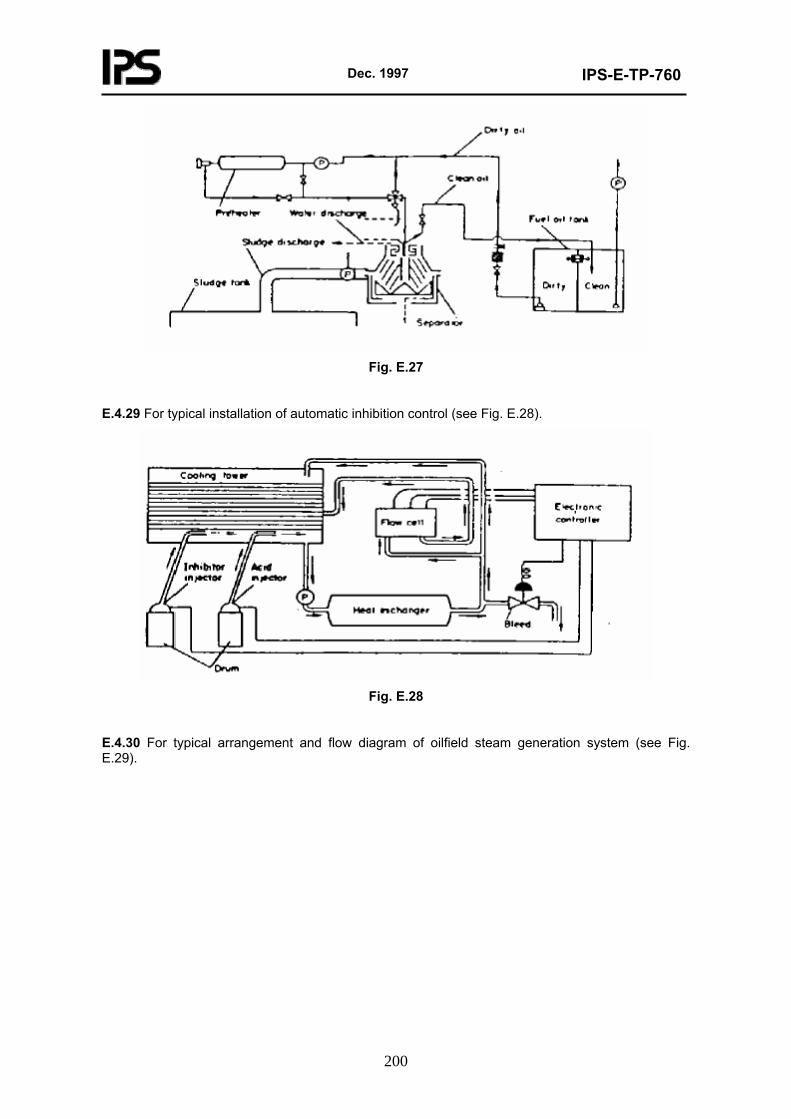
Dec. 1997
IPS-E-TP-760
200
Fig. E.27
E.4.29 For typical installation of automatic inhibition control (see Fig. E.28).
Fig. E.28
E.4.30 For typical arrangement and flow diagram of oilfield steam generation system (see Fig. E.29).
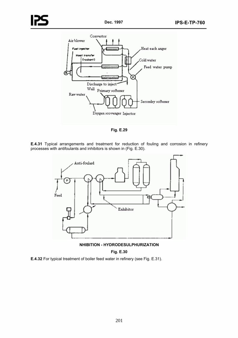
Dec. 1997
IPS-E-TP-760
201
Fig. E.29
E.4.31 Typical arrangements and treatment for reduction of fouling and corrosion in refinery processes with antifoulants and inhibitors is shown in (Fig. E.30).
NHIBITION - HYDRODESULPHURIZATION
Fig. E.30
E.4.32 For typical treatment of boiler feed water in refinery (see Fig. E.31).
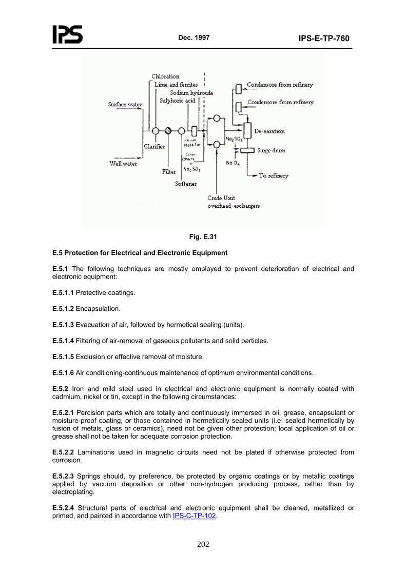
Dec. 1997
IPS-E-TP-760
202
Fig. E.31
E.5 Protection for Electrical and Electronic Equipment
E.5.1 The following techniques are mostly employed to prevent deterioration of electrical and electronic equipment:
E.5.1.1 Protective coatings.
E.5.1.2 Encapsulation.
E.5.1.3 Evacuation of air, followed by hermetical sealing (units).
E.5.1.4 Filtering of air-removal of gaseous pollutants and solid particles.
E.5.1.5 Exclusion or effective removal of moisture.
E.5.1.6 Air conditioning-continuous maintenance of optimum environmental conditions.
E.5.2 Iron and mild steel used in electrical and electronic equipment is normally coated with cadmium, nickel or tin, except in the following circumstances:
E.5.2.1 Percision parts which are totally and continuously immersed in oil, grease, encapsulant or moisture-proof coating, or those contained in hermetically sealed units (i.e. sealed hermetically by fusion of metals, glass or ceramics), need not be given other protection; local application of oil or grease shall not be taken for adequate corrosion protection.
E.5.2.2 Laminations used in magnetic circuits need not be plated if otherwise protected from corrosion.
E.5.2.3 Springs should, by preference, be protected by organic coatings or by metallic coatings applied by vacuum deposition or other non-hydrogen producing process, rather than by electroplating.
E.5.2.4 Structural parts of electrical and electronic equipment shall be cleaned, metallized or primed, and painted in accordance with IPS-C-TP-102.
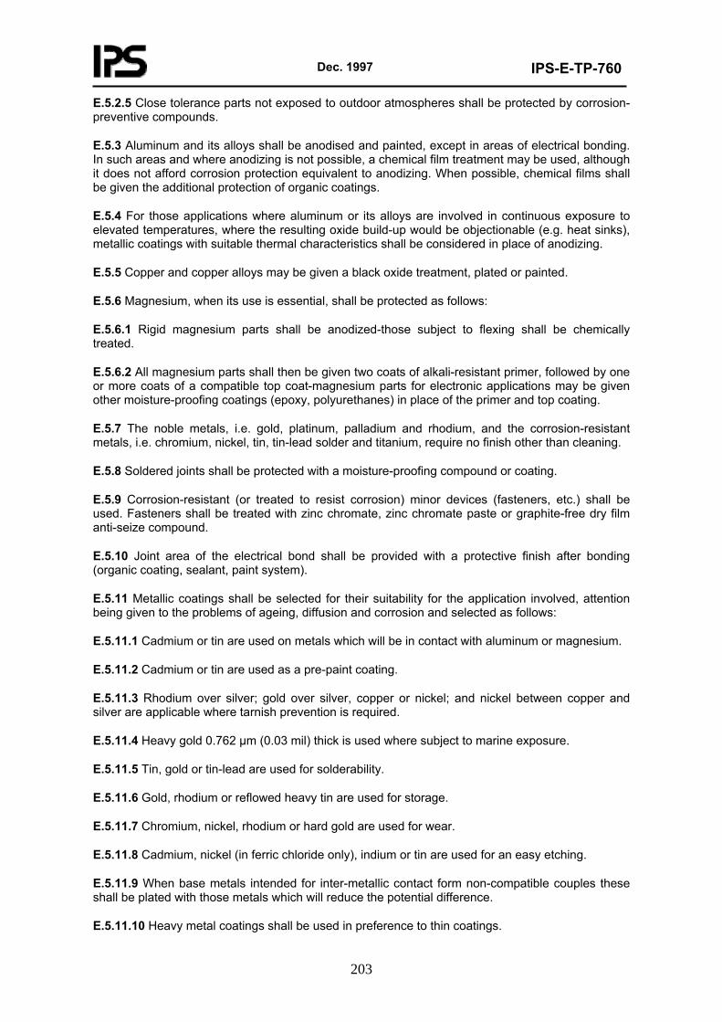
Dec. 1997
IPS-E-TP-760
203
E.5.2.5 Close tolerance parts not exposed to outdoor atmospheres shall be protected by corrosion-preventive compounds.
E.5.3 Aluminum and its alloys shall be anodised and painted, except in areas of electrical bonding. In such areas and where anodizing is not possible, a chemical film treatment may be used, although it does not afford corrosion protection equivalent to anodizing. When possible, chemical films shall be given the additional protection of organic coatings.
E.5.4 For those applications where aluminum or its alloys are involved in continuous exposure to elevated temperatures, where the resulting oxide build-up would be objectionable (e.g. heat sinks), metallic coatings with suitable thermal characteristics shall be considered in place of anodizing.
E.5.5 Copper and copper alloys may be given a black oxide treatment, plated or painted.
E.5.6 Magnesium, when its use is essential, shall be protected as follows:
E.5.6.1 Rigid magnesium parts shall be anodized-those subject to flexing shall be chemically treated.
E.5.6.2 All magnesium parts shall then be given two coats of alkali-resistant primer, followed by one or more coats of a compatible top coat-magnesium parts for electronic applications may be given other moisture-proofing coatings (epoxy, polyurethanes) in place of the primer and top coating.
E.5.7 The noble metals, i.e. gold, platinum, palladium and rhodium, and the corrosion-resistant metals, i.e. chromium, nickel, tin, tin-lead solder and titanium, require no finish other than cleaning.
E.5.8 Soldered joints shall be protected with a moisture-proofing compound or coating.
E.5.9 Corrosion-resistant (or treated to resist corrosion) minor devices (fasteners, etc.) shall be used. Fasteners shall be treated with zinc chromate, zinc chromate paste or graphite-free dry film anti-seize compound.
E.5.10 Joint area of the electrical bond shall be provided with a protective finish after bonding (organic coating, sealant, paint system).
E.5.11 Metallic coatings shall be selected for their suitability for the application involved, attention being given to the problems of ageing, diffusion and corrosion and selected as follows:
E.5.11.1 Cadmium or tin are used on metals which will be in contact with aluminum or magnesium.
E.5.11.2 Cadmium or tin are used as a pre-paint coating.
E.5.11.3 Rhodium over silver; gold over silver, copper or nickel; and nickel between copper and silver are applicable where tarnish prevention is required.
E.5.11.4 Heavy gold 0.762 µm (0.03 mil) thick is used where subject to marine exposure.
E.5.11.5 Tin, gold or tin-lead are used for solderability.
E.5.11.6 Gold, rhodium or reflowed heavy tin are used for storage.
E.5.11.7 Chromium, nickel, rhodium or hard gold are used for wear.
E.5.11.8 Cadmium, nickel (in ferric chloride only), indium or tin are used for an easy etching.
E.5.11.9 When base metals intended for inter-metallic contact form non-compatible couples these shall be plated with those metals which will reduce the potential difference.
E.5.11.10 Heavy metal coatings shall be used in preference to thin coatings.
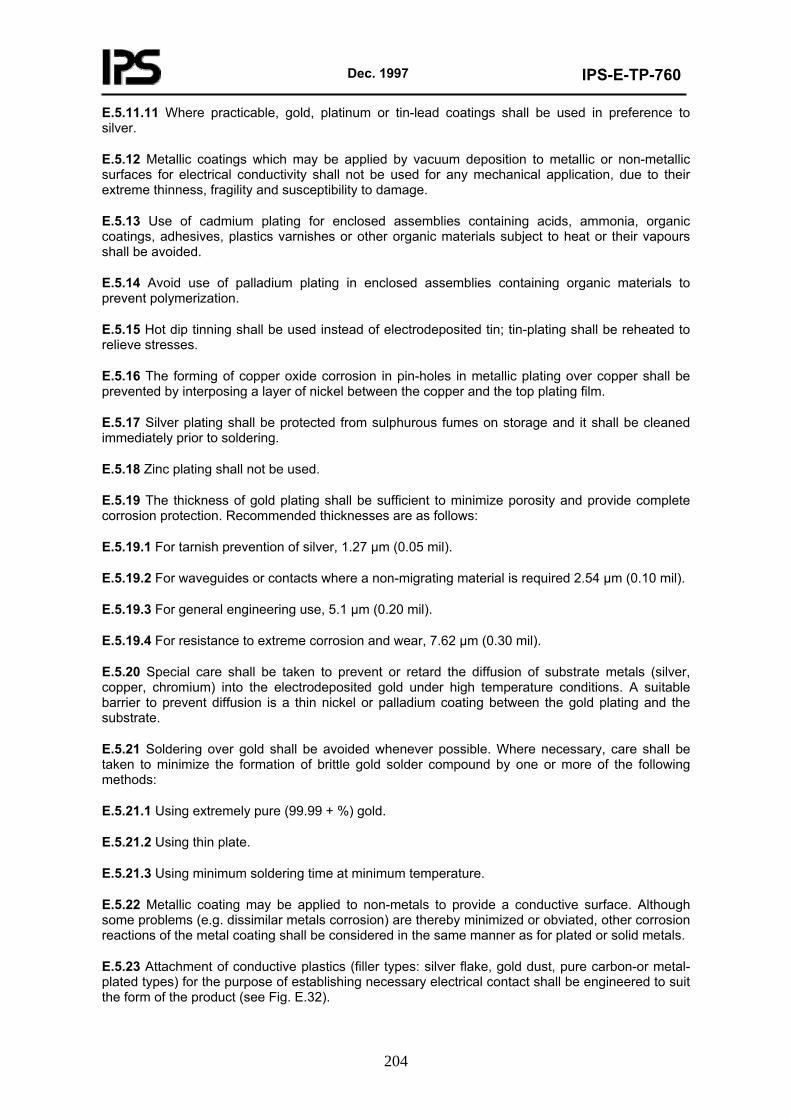
Dec. 1997
IPS-E-TP-760
204
E.5.11.11 Where practicable, gold, platinum or tin-lead coatings shall be used in preference to silver.
E.5.12 Metallic coatings which may be applied by vacuum deposition to metallic or non-metallic surfaces for electrical conductivity shall not be used for any mechanical application, due to their extreme thinness, fragility and susceptibility to damage.
E.5.13 Use of cadmium plating for enclosed assemblies containing acids, ammonia, organic coatings, adhesives, plastics varnishes or other organic materials subject to heat or their vapours shall be avoided.
E.5.14 Avoid use of palladium plating in enclosed assemblies containing organic materials to prevent polymerization.
E.5.15 Hot dip tinning shall be used instead of electrodeposited tin; tin-plating shall be reheated to relieve stresses.
E.5.16 The forming of copper oxide corrosion in pin-holes in metallic plating over copper shall be prevented by interposing a layer of nickel between the copper and the top plating film.
E.5.17 Silver plating shall be protected from sulphurous fumes on storage and it shall be cleaned immediately prior to soldering.
E.5.18 Zinc plating shall not be used.
E.5.19 The thickness of gold plating shall be sufficient to minimize porosity and provide complete corrosion protection. Recommended thicknesses are as follows:
E.5.19.1 For tarnish prevention of silver, 1.27 µm (0.05 mil).
E.5.19.2 For waveguides or contacts where a non-migrating material is required 2.54 µm (0.10 mil).
E.5.19.3 For general engineering use, 5.1 µm (0.20 mil).
E.5.19.4 For resistance to extreme corrosion and wear, 7.62 µm (0.30 mil).
E.5.20 Special care shall be taken to prevent or retard the diffusion of substrate metals (silver, copper, chromium) into the electrodeposited gold under high temperature conditions. A suitable barrier to prevent diffusion is a thin nickel or palladium coating between the gold plating and the substrate.
E.5.21 Soldering over gold shall be avoided whenever possible. Where necessary, care shall be taken to minimize the formation of brittle gold solder compound by one or more of the following methods:
E.5.21.1 Using extremely pure (99.99 + %) gold.
E.5.21.2 Using thin plate.
E.5.21.3 Using minimum soldering time at minimum temperature.
E.5.22 Metallic coating may be applied to non-metals to provide a conductive surface. Although some problems (e.g. dissimilar metals corrosion) are thereby minimized or obviated, other corrosion reactions of the metal coating shall be considered in the same manner as for plated or solid metals.
E.5.23 Attachment of conductive plastics (filler types: silver flake, gold dust, pure carbon-or metal-plated types) for the purpose of establishing necessary electrical contact shall be engineered to suit the form of the product (see Fig. E.32).
Dec. 1997
IPS-E-TP-760
205
Fig. E.32
E.5.24 The ideal coating for an electrical circuit (jelly-type, foam-type, rigid, elastomeric, aerosol-type varnishes) shields it from environmental conditions mechanically, electrically and chemically without affecting the circuit’s original characteristics. The coating shall serve the following basic purposes.
E.5.24.1 Environmental protection to seal out moisture and other airborne contaminants, especially salts and sulphur compounds.
E.5.24.2 Handling protection to prevent damage from hand-borne contaminants (salts, oils, sulphur compounds) which are deposited on component during the final assembly or field testing.
E.5.24.3 "Ruggedisation" against shock or vibration for protection during in-plant handling, testing and final use.
E.5.24.4 Insulation protection to maintain the electronic circuitry in a condition very close to its sterile design environment.
E.5.25 Organic or inorganic coatings, when used, shall be compatible with the substrate.
E.5.26 Protective coatings shall be applied after all punching, drilling, machining, forming and fabrication have been completed. Paint finishing systems, if required, may also be applied after metal deposition or over chemical film treatment.
E.5.27 Corrosion-resistant steels shall be passivated. No further finish is required to provide corrosion resistance to steel of the 300 series; where tarnish, rust or surface stain would be objectionable the 400 series and precipitationhardening steels shall be given additional protection by a suitable plating or, after passivation, they shall receive one coat of zinc chromate primer followed by a suitable top coat.
E.5.28 Soldered joints shall be moisture proofed and the joint area of an electrical bond shall, after bonding, be provided with a protective finish (organic coating, sealant, paint system). All contaminants shall be removed from conductor surfaces.
E.5.29 Direct corrosive environment away from critical equipment by judicious use of drainage and ventilation.
E.5.30 Condensation shall be precluded, by keeping components at temperatures above the dew-point.
E.5.31 Unless specified otherwise, the moisture level inside electronic equipment shall be maintained below 30% RH at 20°C (68°F).
E.5.32 Moisture shall be further excluded from electronic devices by adequate housing, seals, gaskets and closures (see Section 8).
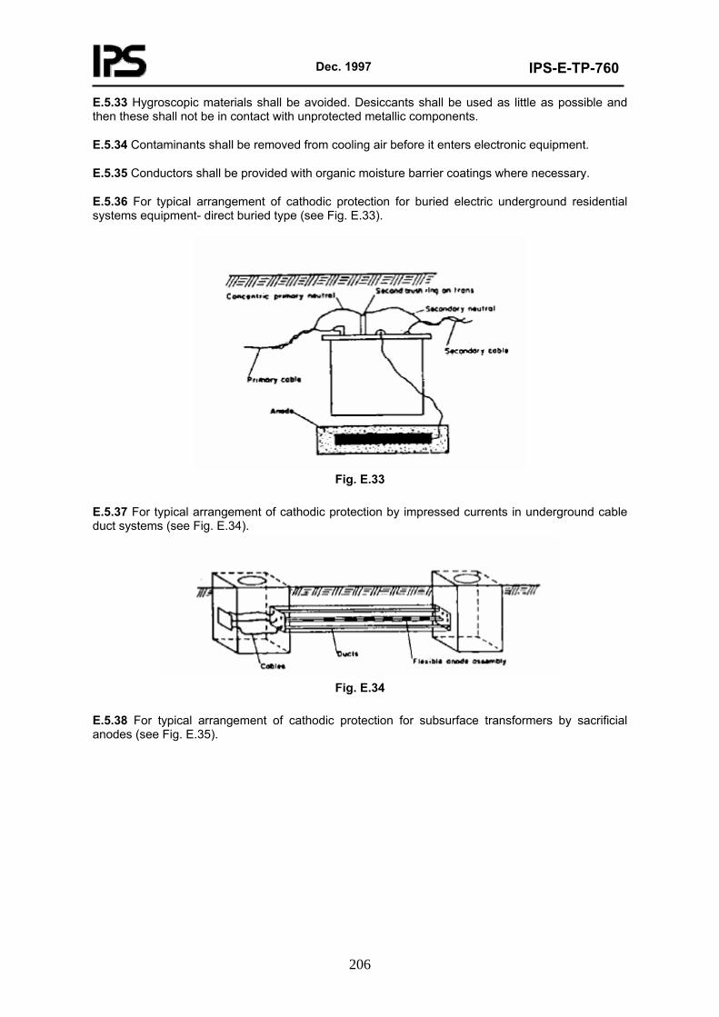
Dec. 1997
IPS-E-TP-760
206
E.5.33 Hygroscopic materials shall be avoided. Desiccants shall be used as little as possible and then these shall not be in contact with unprotected metallic components.
E.5.34 Contaminants shall be removed from cooling air before it enters electronic equipment.
E.5.35 Conductors shall be provided with organic moisture barrier coatings where necessary.
E.5.36 For typical arrangement of cathodic protection for buried electric underground residential systems equipment- direct buried type (see Fig. E.33).
Fig. E.33
E.5.37 For typical arrangement of cathodic protection by impressed currents in underground cable duct systems (see Fig. E.34).
Fig. E.34
E.5.38 For typical arrangement of cathodic protection for subsurface transformers by sacrificial anodes (see Fig. E.35).
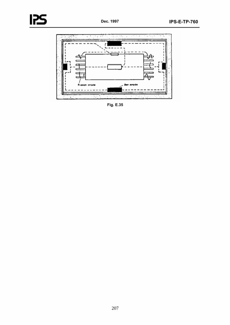
Dec. 1997
IPS-E-TP-760
207
Fig. E.35
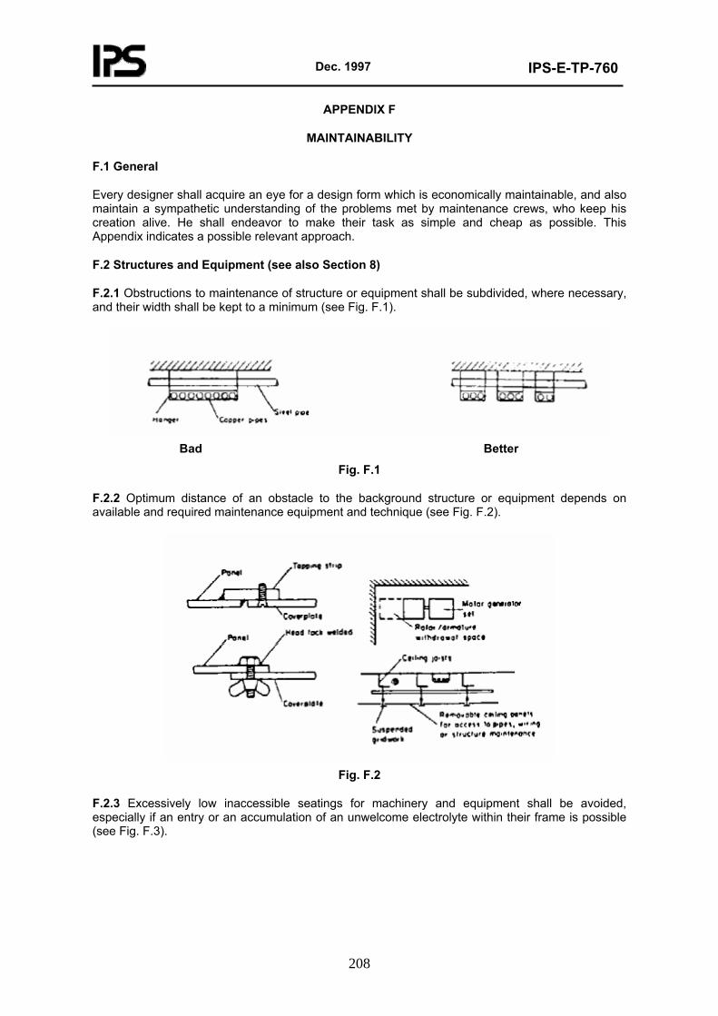
Dec. 1997
IPS-E-TP-760
208
APPENDIX F
MAINTAINABILITY
F.1 General
Every designer shall acquire an eye for a design form which is economically maintainable, and also maintain a sympathetic understanding of the problems met by maintenance crews, who keep his creation alive. He shall endeavor to make their task as simple and cheap as possible. This Appendix indicates a possible relevant approach.
F.2 Structures and Equipment (see also Section 8)
F.2.1 Obstructions to maintenance of structure or equipment shall be subdivided, where necessary, and their width shall be kept to a minimum (see Fig. F.1).
Bad Better
Fig. F.1
F.2.2 Optimum distance of an obstacle to the background structure or equipment depends on available and required maintenance equipment and technique (see Fig. F.2).
Fig. F.2
F.2.3 Excessively low inaccessible seatings for machinery and equipment shall be avoided, especially if an entry or an accumulation of an unwelcome electrolyte within their frame is possible (see Fig. F.3).
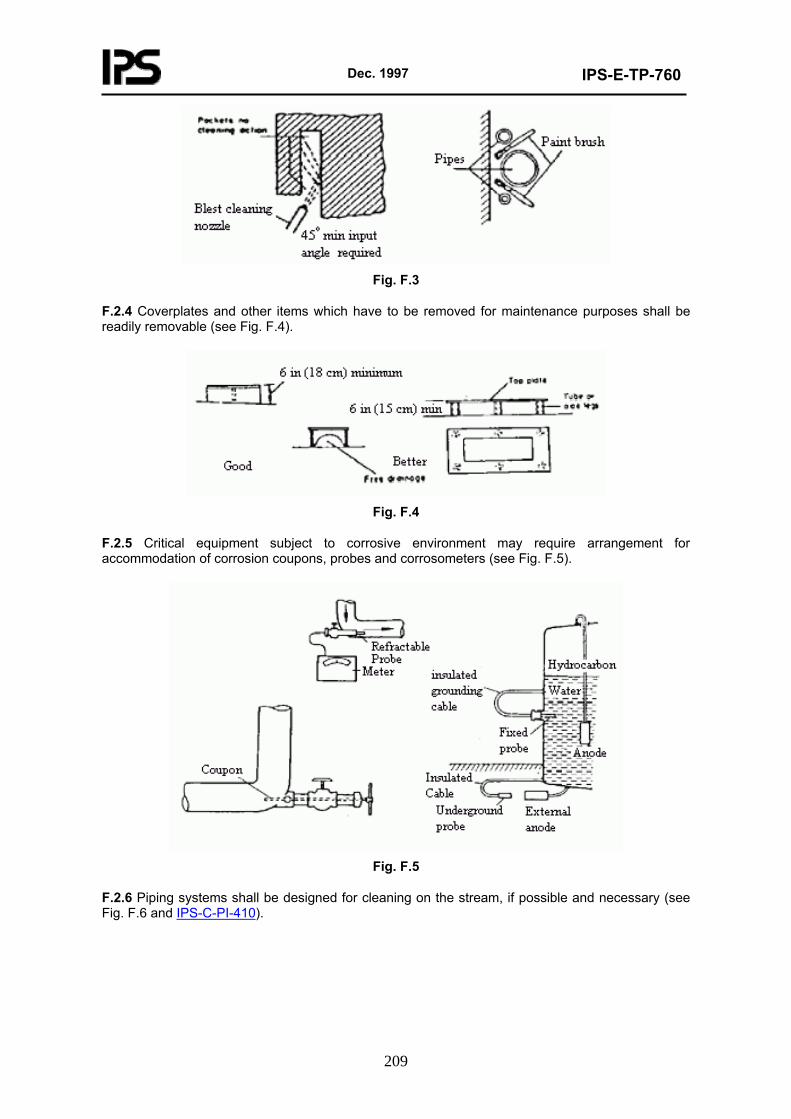
Dec. 1997
IPS-E-TP-760
209
Fig. F.3
F.2.4 Coverplates and other items which have to be removed for maintenance purposes shall be readily removable (see Fig. F.4).
Fig. F.4
F.2.5 Critical equipment subject to corrosive environment may require arrangement for accommodation of corrosion coupons, probes and corrosometers (see Fig. F.5).
Fig. F.5
F.2.6 Piping systems shall be designed for cleaning on the stream, if possible and necessary (see Fig. F.6 and IPS-C-PI-410).
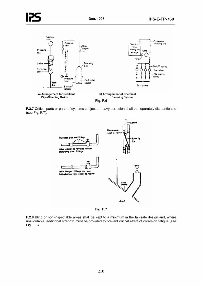
Dec. 1997
IPS-E-TP-760
210
a) Arrangement for Resilient b) Arrangement of Chemical Pipe-Cleaning Swipe Cleaning System.
Fig. F.6
F.2.7 Critical parts or parts of systems subject to heavy corrosion shall be separately dismantleable (see Fig. F.7).
Fig. F.7
F.2.8 Blind or non-inspectable areas shall be kept to a minimum in the fail-safe design and, where unavoidable, additional strength must be provided to prevent critical effect of corrosion fatigue (see Fig. F.8).
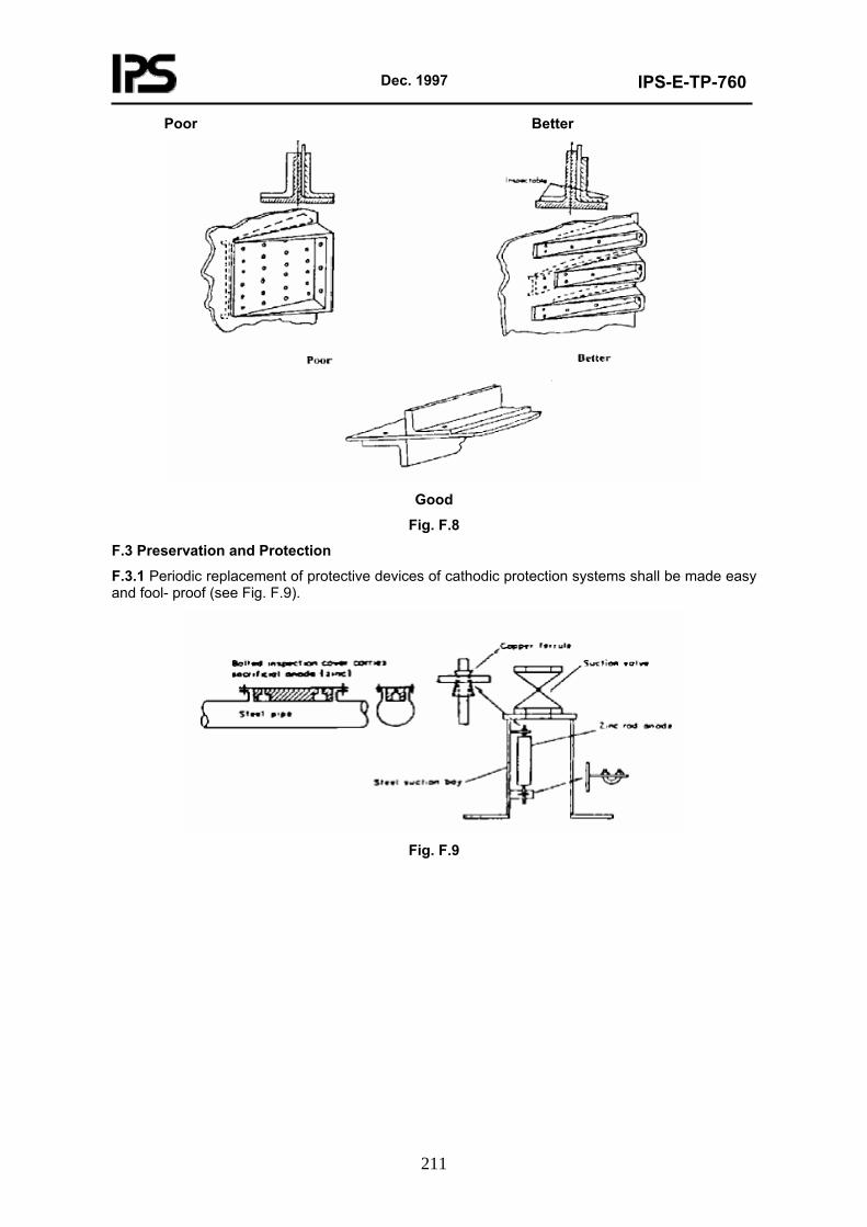
Dec. 1997
IPS-E-TP-760
211
Poor Better
Good
Fig. F.8
F.3 Preservation and Protection
F.3.1 Periodic replacement of protective devices of cathodic protection systems shall be made easy and fool- proof (see Fig. F.9).
Fig. F.9
Dec. 1997
IPS-E-TP-760
212
APPENDIX G
ECONOMICS
G.1 General
This Appendix provides special guidance, regarding the corrosion control, which shall be considered by the designer of structures, equipment and piping systems.
G.2 Economics Applied to Structures
G.2.1 The cost of structural steel design is closely related to the weight of steel used in the design; the cost of fabrication, shipping, erection, aesthetics, maintenance and corrosion control increases with the increase of weight of steel in the structure. Amongst the other savings which accrue from lighter steel weights one may also count the occasional profit resulting from greater payloads.
G.2.2 Reduction in weight of structures permissible by smaller loss of strength integrity through improved corrosion control stands for direct savings in costs. The reduction of materials cost is the major consideration; fabrication cost including processing and others shall also be calculated.
G.2.3 Trade-in between improvement of corrosion control and reduction of weight or vice versa shall be considered multilaterally.
G.2.4 Some special considerations, such as improvement of notch toughness and other precautions against stress corrosion cracking at low temperatures for cryogenic tanks, ships and submarine design, are specifically relevant in individual cases of economic evaluation.
G.2.5 Corrosion control which allows planned elimination or reduction of labour motions or shop operations can reduce costs:
G.2.5.1 Rolled shapes of any grade of steel in a structure are in most cases more economical than any built-up shapes of the same size and grade of steel.
G.2.5.2 Rolled shapes of a higher strength may be used to replace lower strength steel shapes requiring flange plates.
G.2.5.3 Thinner plates of higher strength steels can replace thicker plates of lower strength steels.
Note: Consider reduction in cost of welding and danger of stress corrosion cracking and fatigue corrosion.
G.2.6 The equipment used during erection of structures and the time of erection is not necessarily reduced simply by reduction of the weight of the handled components.
Note: For calculation of costs.
G.2.7 A reduction in weight caused by improved corrosion control may accentuate the aesthetics of the structure and, by its pleasing outline, it may be inductive to a reduction in fabrication and erection costs.
G.2.8 Use of smaller size structural members, due to effective corrosion control, reduces the maintenance costs, e.g. paint and painting time.
G.2.9 Simplification and standardization of structural members, which are conductive to improved corrosion control, also reduce the cost of maintenance and enhance maintainability.
G.2.10 Use of corrosion-wise safer steel in structures may also provide improved economy in tension, in bending, in compression and economy in framing and plating.
Dec. 1997
IPS-E-TP-760
213
G.2.11 Permanent structures designed for a service life of more than five years shall be protected from deterioration with the best coating system available. Other corrosion-control measures shall also be considered. The cost limit in each case is individual and shall not be arbitrarily dictated.
G.2.12 The economics of buying quality materials or techniques for treatment of new construction surfaces can be negated through incomplete specifications, poor application or lack of inspection.
G.2.13 The sequence of economic rating of protective coatings for steel permanent structures:
G.2.13.1 Hot dip galvanizing.
G.2.13.2 Hot metal spray or zinc-rich coatings.
G.2.13.3 High built organic coatings-where zinc or other sacrificial metals cannot resist certain types of corrosion attack and as a sealer for anodic metals containing coatings in places where such metals are easily corroded.
G.2.14 Some economic guidelines for application of various protective coatings for standard components.
G.2.14.1 Below 16 mm (5/8 in) flange thickness the galvanizing is more economic-above this thickness hot metal spray or spray and brush applied coatings are preferred.
G.2.14.2 Galvanizing on the inside and outside of steel piping is more economic up to 30 cm (12 in) OD-above this diameter hot metal spray or spray and brush applied coatings are preferred.
G.2.14.3 Galvanizing is more economic on fabricated vessels up to 1.2 m (4 ft) diameter-above this diameter hot metal spray or brush and spray applied coatings are preferred.
G.2.14.4 Zinc-rich paints (e.g. prefabrication primers) are more economic for plate sections of large field fabricated tanks than other coatings.
G.3 Economics Applied to Equipment and Pipe Systems
G.3.1 The service life of materials contained in any equipment, even when correlated with the corrosion test data, shall be primarily weighed in the light of the actual cost.
G.3.2 Both the damage and the cost of external and internal corrosion shall be considered for evaluation of the service life of hollow equipment and pipe systems.
G.3.3 The effect of occasional and periodical variations of internal and external environmental conditions shall also be evaluated for the true extent of service life of relevant equipment.
G.3.4 Whilst it may not always be possible to estimate the actual money cost of equipment it is possible to make the relevant economic decision with the help of the relative costs for comparison. This applies especially to such equipment for which the price quotations vary so greatly and are influenced by so many factors. Thus it is more meaningful to examine the ways in which the choice of materials may affect primarily the first cost and then the future expenses.
G.3.5 The number of renewals forecast or necessary in the normal life-span of the equipment shall be determined in the economic analysis.
G.3.6 The degree of difficulty of the replacement of equipment or pipeline in a particular location will affect their cost.
G.3.7 The sum of the renewals of equipment is to be multiplied by the sum of labour costs which will accrue through removing and re-installing the equipment in situ and by the sum of material costs, this to obtain a base for the calculations.

Dec. 1997
IPS-E-TP-760
214
G.3.8 Selections providing a safe reduction of weight shall be credited with the side effects of their weight reduction, e.g. lower power needed to haul given payloads, additional earning power through extra cargo capacity at the same consumption of fuel, etc.
G.3.9 Some factors to be considered in the economic evaluation of condensers.
G.3.9.1 Comparative cost of several materials.
G.3.9.2 Size and geometry of condenser to suit the variety of materials.
G.3.9.3 Comparative heat transfer factor (area of surface for a given wall thickness).
G.3.9.4 Cleanliness factor.
G.3.9.5 Compensation for corrosion scales formed on service.
G.3.9.6 Tolerance for velocity of water to suit variety of materials, etc.
G.3.10 For fabricated vessels, organic coatings become more economical at a diameter of 1.2 m (4 ft) or more.
G.3.11 Zinc-rich paints are more economical for the preservation of plate sections of large field-fabricated tanks, water towers, etc.
G.3.12 The comparative throughput of transferred liquids shall be used as a base of economic evaluation instead of the outside diameter of the pipes.
G.3.13 There is no set figure for unscheduled out-of-service time for all equipment within a utility. For example, whilst a leak in a sanitary or service piping system, although undesirable, will not stop the normal operation of a ship, a leak in a tube of a main condenser will stop the ship for cooling down, opening up, plugging the leaking tube and the close down.
G.3.14 It is more economical to galvanize both the inside and outside of pipes of up to 30 cm (12 in) OD.
G.3.15 Longer life expectancy can be expected from larger diameter pipes than from the smaller diameter ones.
G.3.16 Life expectancy of tubes and pipes cannot be judged on their nominal pipe thickness. Reasons: tolerances in nominal thickness; metal removed in threading will considerably reduce the wall thickness which a pit must penetrate.
G.3.17 Life expectancy of pipes cannot be judged solely on the available pitting data; these tend to vary a lot. Rate of penetration is not affected by pitting only; impingement attack, erosion, etc., shall be taken into account.
G.3.18 Pitting and preferential corrosion in the vicinity of welds make the available weight loss data of some austenitic stainless steels meaningless; note the loss in local pits or in adjacent welds.
G.3.19 Note, in life expectancy calculations of condenser tube materials, that the test data on their specimen do not ordinarily reflect the hot-wall effect.
G.3.20 Economic evaluation of any equipment shall not be based on any single portion of this equipment but on a balanced investigation of the whole system.
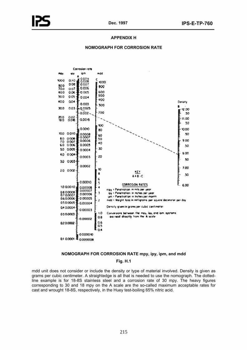
Dec. 1997
IPS-E-TP-760
215
APPENDIX H
NOMOGRAPH FOR CORROSION RATE
NOMOGRAPH FOR CORROSION RATE mpy, ipy, ipm, and mdd
Fig. H.1
mdd unit does not consider or include the density or type of material involved. Density is given as grams per cubic centimeter. A straightedge is all that is needed to use the nomograph. The dotted-line example is for 18-8S stainless steel and a corrosion rate of 30 mpy. The heavy figures corresponding to 30 and 18 mpy on the A scale are the so-called maximum acceptable rates for cast and wrought 18-8S, respectively, in the Huey test-boiling 65% nitric acid.
Dec. 1997
IPS-E-TP-760
216
APPENDIX I
FORMS OF CORROSION AND PREVENTIVE MEASURES
- This Engineering Standard is specialized for corrosion engineers and is a guide for the designers of petroleum equipment, production units, pipelines, refineries, petrochemicals and related structures.
- The purpose of corrosion consideration in design is to avoid or minimize corrosion hazards technically and economically and to try assurance of longer life of selected materials and constructed structures and equipment.
- The designer, material engineer and corrosion engineer must work closely together to ensure that premature failure will not occur because of design defects or improper material selection.
- Basic forms of corrosion and the prevention methods are discussed in appendix I below in order to be considered during the design stages and help the parties involved to analyze the project regarding the corrosion.
I.1 Forms of Corrosion and Preventive Measures
Eight forms of corrosion are classified, in general based on the appearance of the corroded materials. Each form can be identified by more visual observation. The naked eye may be sufficient, but sometimes magnification is helpful. Careful observation of the corroded test specimens help to solve the corrosion problems. Examination "Before" cleaning is particularly desirable.
These eight forms of corrosion being more or less interrelated are as follows:
- Uniform or general corrosion
- Galvanic or two metal corrosion
- Crevice corrosion
- Pitting
- Intergranular corrosion
- Selective leaching or parting
- Erosion-corrosion
- Stress corrosion
I.1.1 Uniform or general corrosion
Uniform attack on metal is the common form of corrosion characterized by a chemical or electrochemical reaction that proceeds uniformly over the entire exposed surface. The metal becomes thinner and eventually fails. A piece of zinc dissolves in sulfuric acid at a uniform rate. This form of corrosion represents the greatest destruction of metal on a tonage Zbasis.
The life of the metal may be accurately estimated (nomograph for estimating corrosion penetration rate is shown in Appendix H).
I.1.1.1 Prevention
Uniform attack can be prevented or reduced by using:
- Proper materials, including coatings;
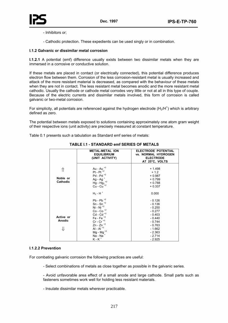
Dec. 1997
IPS-E-TP-760
217
- Inhibitors or;
- Cathodic protection. These expedients can be used singly or in combination.
I.1.2 Galvanic or dissimilar metal corrosion
I.1.2.1 A potential (emf) difference usually exists between two dissimilar metals when they are immersed in a corrosive or conductive solution.
If these metals are placed in contact (or electrically connected), this potential difference produces electron flow between them. Corrosion of the less corrosion-resistant metal is usually increased and attack of the more resistant material is decreased, as compared with the behaviour of these metals when they are not in contact. The less resistant metal becomes anodic and the more resistant metal cathodic. Usually the cathode or cathode metal corrodes very little or not at all in this type of couple. Because of the electric currents and dissimilar metals involved, this form of corrosion is called galvanic or two-metal corrosion.
For simplicity, all potentials are referenced against the hydrogen electrode (H2/H+) which is arbitrary defined as zero.
The potential between metals exposed to solutions containing approximately one atom gram weight of their respective ions (unit activity) are precisely measured at constant temperature.
Table 0.1 presents such a tabulation as Standard emf series of metals:
TABLE I.1 - STANDARD emf SERIES OF METALS METAL-METAL ION
EQUILIBRIUM (UNIT ACTIVITY)
ELECTRODE POTENTIAL vs. NORMAL HYDROGEN
ELECTRODE AT 25°C, VOLTS
⇑
Noble or Cathodic
Active or Anodic
⇓
Au - Au +3 Pt - Pt +2 Pd - Pd +2 Ag - Ag + Hg - Hg2
+2 Cu - Cu +2 H2 - H + Pb - Pb +2 Sn - Sn +2 Ni - Ni +2 Co - Co +2 Cd - Cd +2 Fe - Fe +2 Cr - Cr +3 Zn - Zn +2 Al - Al +3 Mg - Mg +2 Na - Na + K - K +
+ 1.498 + 1.2
+ 0.987 + 0.799 + 0.788 + 0.337
0.000
- 0.126 - 0.136 - 0.250 - 0.277 - 0.403 - 0.440 - 0.744 - 0.763 - 1.662 - 2.363 - 2.714 - 2.925
I.1.2.2 Prevention
For combating galvanic corrosion the following practices are useful:
- Select combinations of metals as close together as possible in the galvanic series.
- Avoid unfavorable area effect of a small anode and large cathode. Small parts such as fasteners sometimes work well for holding less resistant materials.
- Insulate dissimilar metals wherever practicable.
Dec. 1997
IPS-E-TP-760
218
- Apply coating with caution.
- Add inhibitors, if possible, to decrease aggressiveness of the environment.
- Avoid threaded joints for materials far apart in the galvanic series.
- Design for the use of readily replaceable parts or make them thicker for longer life.
- Install a third metal that is anodic to both metals in the galvanic contact.
I.1.3 Crevice corrosion
I.1.3.1 Intensive localized corrosion frequently occurs within crevices and other shielded areas on metal surfaces exposed to corrosives. The attack associated with small volumes of stagnant solution caused by holes, gasket surfaces, lap joints, surface deposits, and crevices under bolt and rivet heads.
I.1.3.2 Combating crevice corrosion
Methods and procedures for combating crevice corrosion are as follows:
- Use welded butt joints instead of riveted or bolted joints in new equipment.
- Close crevices in existing lap joints by continuous welding, caulking or soldering.
- Design vessels for complete drainage; avoid sharp corners and stagnant areas.
- Inspect equipment and remove deposits frequently.
- Remove solids in suspension early in the process or plant flow sheet, if possible.
- Remove wet packing materials during long shutdowns.
- Provide uniform environments, if possible, as in the case of back-filling a pipeline trench.
- Use "solid" non-absorbent gaskets, such as teflon, whenever possible.
- Weld instead of rolling in tubes, in tube sheets.
I.1.4 Pitting
I.1.4.1 Pitting is a form of extremely localized attack. That results in holes in the metal. It is a cavity or hole with the surface diameter about the same as or less than the depth.
Pitting is one of the most destructive form of corrosion, it causes equipment to fail because of perforation with only a small percent weight loss of the entire structure. Pitting may be considered as the intermediate stage between general overall corrosion and complete corrosion resistance. This is shown diagramatically in Fig. 0.1.
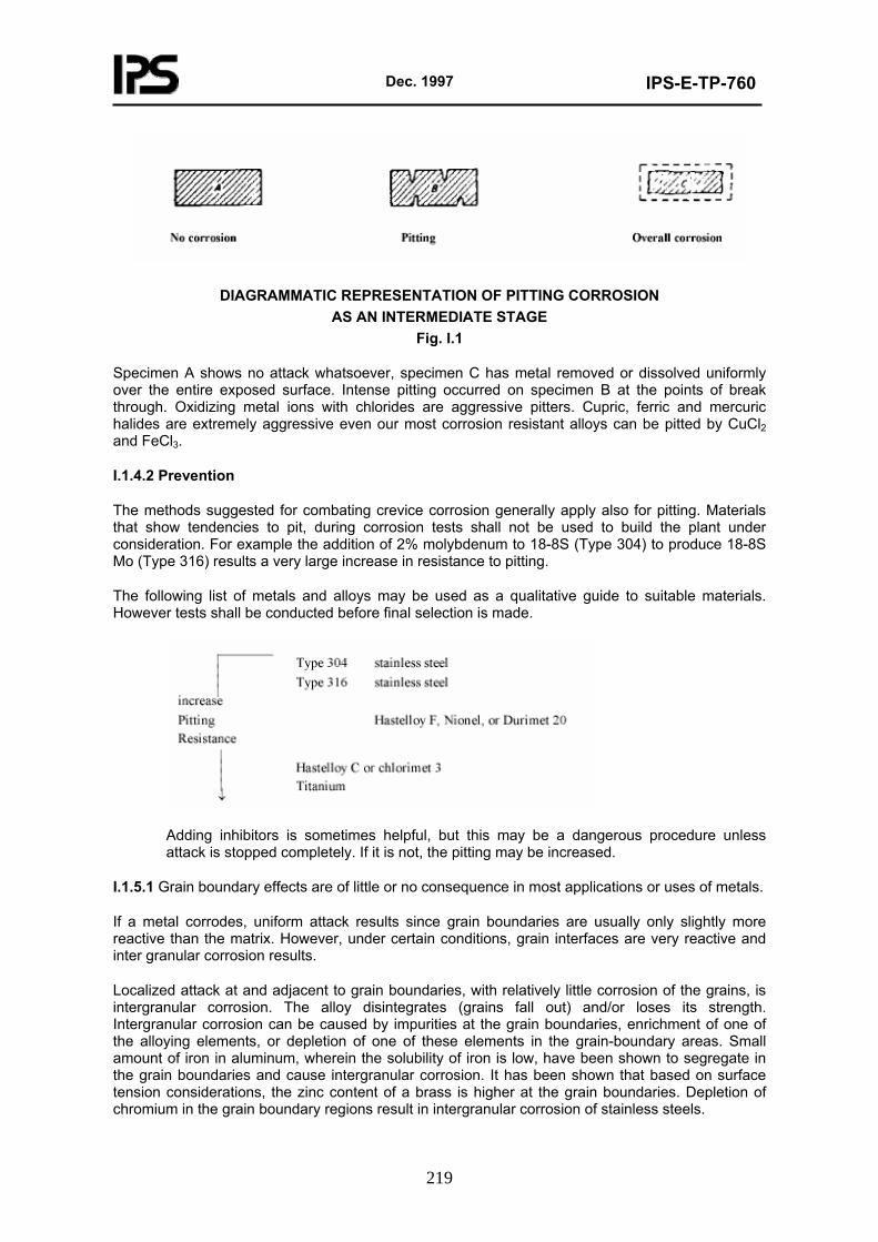
Dec. 1997
IPS-E-TP-760
219
DIAGRAMMATIC REPRESENTATION OF PITTING CORROSION AS AN INTERMEDIATE STAGE
Fig. I.1
Specimen A shows no attack whatsoever, specimen C has metal removed or dissolved uniformly over the entire exposed surface. Intense pitting occurred on specimen B at the points of break through. Oxidizing metal ions with chlorides are aggressive pitters. Cupric, ferric and mercuric halides are extremely aggressive even our most corrosion resistant alloys can be pitted by CuCl2 and FeCl3.
I.1.4.2 Prevention
The methods suggested for combating crevice corrosion generally apply also for pitting. Materials that show tendencies to pit, during corrosion tests shall not be used to build the plant under consideration. For example the addition of 2% molybdenum to 18-8S (Type 304) to produce 18-8S Mo (Type 316) results a very large increase in resistance to pitting.
The following list of metals and alloys may be used as a qualitative guide to suitable materials. However tests shall be conducted before final selection is made.
Adding inhibitors is sometimes helpful, but this may be a dangerous procedure unless attack is stopped completely. If it is not, the pitting may be increased.
I.1.5.1 Grain boundary effects are of little or no consequence in most applications or uses of metals.
If a metal corrodes, uniform attack results since grain boundaries are usually only slightly more reactive than the matrix. However, under certain conditions, grain interfaces are very reactive and inter granular corrosion results.
Localized attack at and adjacent to grain boundaries, with relatively little corrosion of the grains, is intergranular corrosion. The alloy disintegrates (grains fall out) and/or loses its strength. Intergranular corrosion can be caused by impurities at the grain boundaries, enrichment of one of the alloying elements, or depletion of one of these elements in the grain-boundary areas. Small amount of iron in aluminum, wherein the solubility of iron is low, have been shown to segregate in the grain boundaries and cause intergranular corrosion. It has been shown that based on surface tension considerations, the zinc content of a brass is higher at the grain boundaries. Depletion of chromium in the grain boundary regions result in intergranular corrosion of stainless steels.
Dec. 1997
IPS-E-TP-760
220
I.1.5.2 Austenitic stainless steels
Numerous failures of 18-8 stainless steels (Type 304) have occurred because of inter-granular corrosion. These happen in environments where the alloy expected to exhibit excellent corrosion resistance. When these steels are heated in the temperature range of 370-815°C they become sensitized to intergranular corrosion. For example a procedure to sensitize intentionally is to heat at 650°C for one hour. The process of depletion of chromium in the grain boundary is shown.
The chromium depleted zone near the grain boundary is corroded because it does not contain sufficient corrosion resistance to resist attack, but chromium carbide (Cr23C6) is insoluble and precipitates. Therefore the steel is said to be sensitized to intergranular (inter crystalline) attack.
Note: The detrimental effect of carbon and nitrogen in ferrite can be overcome by changing the crystal structure to austenite, a face-centered cubic (fcc) crystal structure. This change is accomplished by adding austenite stabilizers most commonly Nickel but also manganese and nitrogen. Austenite is characterize as non-magnetic.
I.1.5.3 Control for austenitic stainless steels
I.1.5.3.1 Three methods are used to control or minimize intergranular corrosion of the austenitic stainless steels:
- employing high temperature solution heat treatment which is termed quench-annealing or solution quenching;
- adding elements that are strong carbide formers (called stabilizers), and
- lowering the carbon content to below 0.03%.
I.1.5.3.2 Weld decay
Many failures of 18-8 stainless steel occurred in the early history of this material until the mechanism of intergranular corrosion was understood. Failures still occur when this effect is not considered. These are associated with welded structures, and the material attacked intergranularly is called "weld decay".
I.1.5.3.3 Knife-line Attack (KLA)
Knife-line attack is similar to weld decay and they both result from intergranular corrosion and both are associated with welding. The three major differences are:
- KLA occurs in a narrow band in the base metal immediately adjacent to the weld, whereas weld decay develops at an appreciable distance from the weld.
- KLA occurs in the stabilized steels.
- The thermal history of the metal is different.
I.1.6 Selective leaching or dealloying corrosion
I.1.6.1 Selective leaching is the removal of one element from a solid alloy by corrosion processes. The most common example is the selective removal of zinc in brass alloys (dezincification) similar processes occur in other alloy systems in which aluminum, iron, cobalt, chromium, and other elements are removed. Selective leaching is the general term that describes these processes, and its use precludes the creation of terms such as dealuminumification, decobaltification etc. "Parting" is a metallurgical term that is sometimes applied, but selective leaching is preferred.
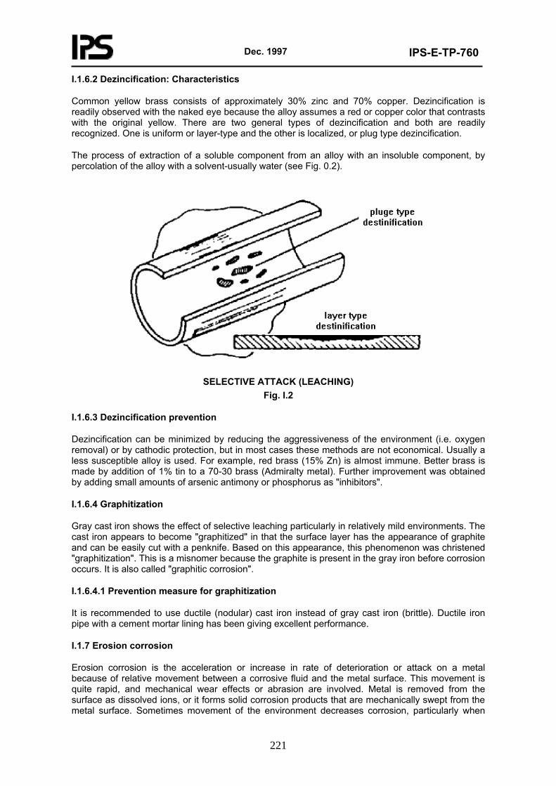
Dec. 1997
IPS-E-TP-760
221
I.1.6.2 Dezincification: Characteristics
Common yellow brass consists of approximately 30% zinc and 70% copper. Dezincification is readily observed with the naked eye because the alloy assumes a red or copper color that contrasts with the original yellow. There are two general types of dezincification and both are readily recognized. One is uniform or layer-type and the other is localized, or plug type dezincification.
The process of extraction of a soluble component from an alloy with an insoluble component, by percolation of the alloy with a solvent-usually water (see Fig. 0.2).
SELECTIVE ATTACK (LEACHING)
Fig. I.2
I.1.6.3 Dezincification prevention
Dezincification can be minimized by reducing the aggressiveness of the environment (i.e. oxygen removal) or by cathodic protection, but in most cases these methods are not economical. Usually a less susceptible alloy is used. For example, red brass (15% Zn) is almost immune. Better brass is made by addition of 1% tin to a 70-30 brass (Admiralty metal). Further improvement was obtained by adding small amounts of arsenic antimony or phosphorus as "inhibitors".
I.1.6.4 Graphitization
Gray cast iron shows the effect of selective leaching particularly in relatively mild environments. The cast iron appears to become "graphitized" in that the surface layer has the appearance of graphite and can be easily cut with a penknife. Based on this appearance, this phenomenon was christened "graphitization". This is a misnomer because the graphite is present in the gray iron before corrosion occurs. It is also called "graphitic corrosion".
I.1.6.4.1 Prevention measure for graphitization
It is recommended to use ductile (nodular) cast iron instead of gray cast iron (brittle). Ductile iron pipe with a cement mortar lining has been giving excellent performance.
I.1.7 Erosion corrosion
Erosion corrosion is the acceleration or increase in rate of deterioration or attack on a metal because of relative movement between a corrosive fluid and the metal surface. This movement is quite rapid, and mechanical wear effects or abrasion are involved. Metal is removed from the surface as dissolved ions, or it forms solid corrosion products that are mechanically swept from the metal surface. Sometimes movement of the environment decreases corrosion, particularly when
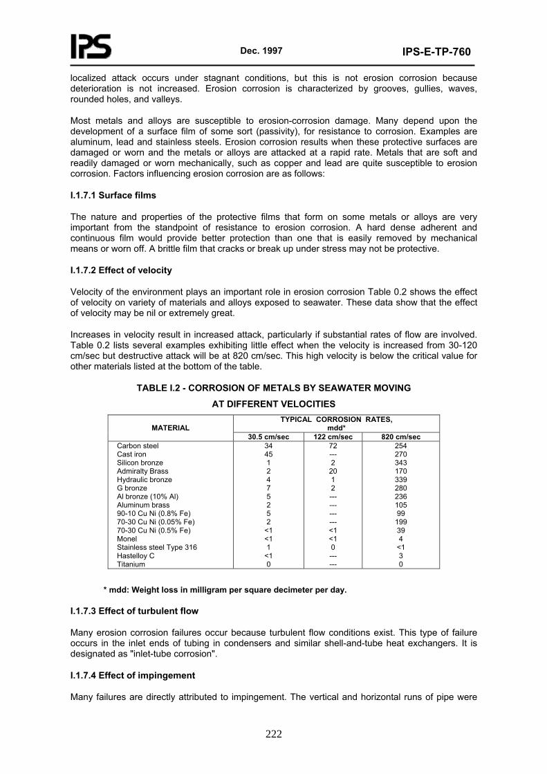
Dec. 1997
IPS-E-TP-760
222
localized attack occurs under stagnant conditions, but this is not erosion corrosion because deterioration is not increased. Erosion corrosion is characterized by grooves, gullies, waves, rounded holes, and valleys.
Most metals and alloys are susceptible to erosion-corrosion damage. Many depend upon the development of a surface film of some sort (passivity), for resistance to corrosion. Examples are aluminum, lead and stainless steels. Erosion corrosion results when these protective surfaces are damaged or worn and the metals or alloys are attacked at a rapid rate. Metals that are soft and readily damaged or worn mechanically, such as copper and lead are quite susceptible to erosion corrosion. Factors influencing erosion corrosion are as follows:
I.1.7.1 Surface films
The nature and properties of the protective films that form on some metals or alloys are very important from the standpoint of resistance to erosion corrosion. A hard dense adherent and continuous film would provide better protection than one that is easily removed by mechanical means or worn off. A brittle film that cracks or break up under stress may not be protective.
I.1.7.2 Effect of velocity
Velocity of the environment plays an important role in erosion corrosion Table 0.2 shows the effect of velocity on variety of materials and alloys exposed to seawater. These data show that the effect of velocity may be nil or extremely great.
Increases in velocity result in increased attack, particularly if substantial rates of flow are involved. Table 0.2 lists several examples exhibiting little effect when the velocity is increased from 30-120 cm/sec but destructive attack will be at 820 cm/sec. This high velocity is below the critical value for other materials listed at the bottom of the table.
TABLE I.2 - CORROSION OF METALS BY SEAWATER MOVING
AT DIFFERENT VELOCITIES TYPICAL CORROSION RATES,
mdd*
MATERIAL 30.5 cm/sec 122 cm/sec 820 cm/sec
Carbon steel Cast iron Silicon bronze Admiralty Brass Hydraulic bronze G bronze Al bronze (10% Al) Aluminum brass 90-10 Cu Ni (0.8% Fe) 70-30 Cu Ni (0.05% Fe) 70-30 Cu Ni (0.5% Fe) Monel Stainless steel Type 316 Hastelloy C Titanium
34 45 1 2 4 7 5 2 5 2
<1 <1 1
<1 0
72 --- 2
20 1 2 --- --- --- --- <1 <1 0 --- ---
254 270 343 170 339 280 236 105 99
199 39 4
<1 3 0
* mdd: Weight loss in milligram per square decimeter per day.
I.1.7.3 Effect of turbulent flow
Many erosion corrosion failures occur because turbulent flow conditions exist. This type of failure occurs in the inlet ends of tubing in condensers and similar shell-and-tube heat exchangers. It is designated as "inlet-tube corrosion".
I.1.7.4 Effect of impingement
Many failures are directly attributed to impingement. The vertical and horizontal runs of pipe were
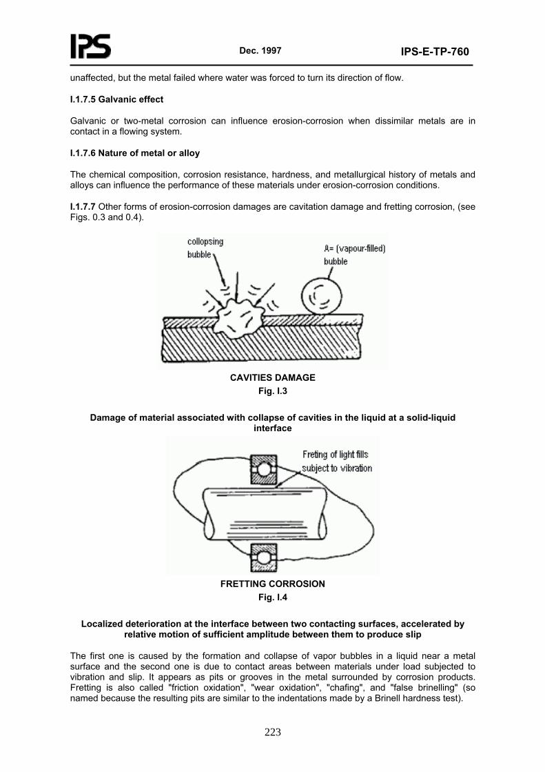
Dec. 1997
IPS-E-TP-760
223
unaffected, but the metal failed where water was forced to turn its direction of flow.
I.1.7.5 Galvanic effect
Galvanic or two-metal corrosion can influence erosion-corrosion when dissimilar metals are in contact in a flowing system.
I.1.7.6 Nature of metal or alloy
The chemical composition, corrosion resistance, hardness, and metallurgical history of metals and alloys can influence the performance of these materials under erosion-corrosion conditions.
I.1.7.7 Other forms of erosion-corrosion damages are cavitation damage and fretting corrosion, (see Figs. 0.3 and 0.4).
CAVITIES DAMAGE
Fig. I.3
Damage of material associated with collapse of cavities in the liquid at a solid-liquid interface
FRETTING CORROSION
Fig. I.4
Localized deterioration at the interface between two contacting surfaces, accelerated by relative motion of sufficient amplitude between them to produce slip
The first one is caused by the formation and collapse of vapor bubbles in a liquid near a metal surface and the second one is due to contact areas between materials under load subjected to vibration and slip. It appears as pits or grooves in the metal surrounded by corrosion products. Fretting is also called "friction oxidation", "wear oxidation", "chafing", and "false brinelling" (so named because the resulting pits are similar to the indentations made by a Brinell hardness test).
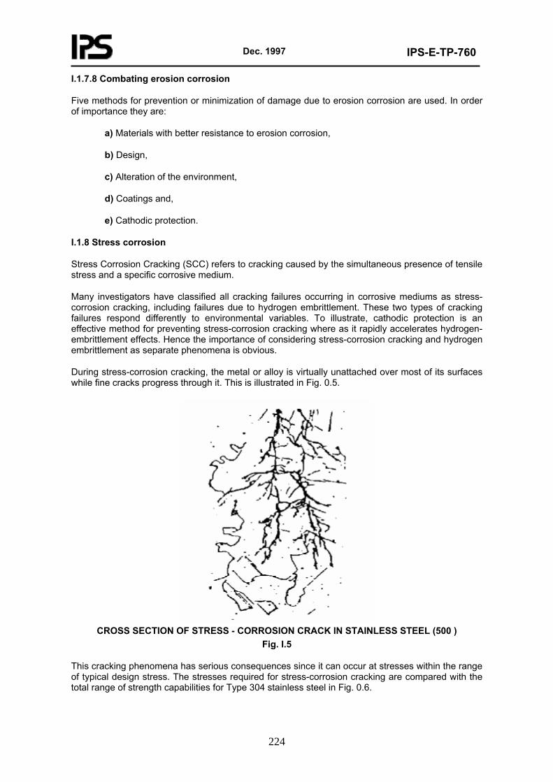
Dec. 1997
IPS-E-TP-760
224
I.1.7.8 Combating erosion corrosion
Five methods for prevention or minimization of damage due to erosion corrosion are used. In order of importance they are:
a) Materials with better resistance to erosion corrosion,
b) Design,
c) Alteration of the environment,
d) Coatings and,
e) Cathodic protection.
I.1.8 Stress corrosion
Stress Corrosion Cracking (SCC) refers to cracking caused by the simultaneous presence of tensile stress and a specific corrosive medium.
Many investigators have classified all cracking failures occurring in corrosive mediums as stress-corrosion cracking, including failures due to hydrogen embrittlement. These two types of cracking failures respond differently to environmental variables. To illustrate, cathodic protection is an effective method for preventing stress-corrosion cracking where as it rapidly accelerates hydrogen-embrittlement effects. Hence the importance of considering stress-corrosion cracking and hydrogen embrittlement as separate phenomena is obvious.
During stress-corrosion cracking, the metal or alloy is virtually unattached over most of its surfaces while fine cracks progress through it. This is illustrated in Fig. 0.5.
CROSS SECTION OF STRESS - CORROSION CRACK IN STAINLESS STEEL (500 )
Fig. I.5
This cracking phenomena has serious consequences since it can occur at stresses within the range of typical design stress. The stresses required for stress-corrosion cracking are compared with the total range of strength capabilities for Type 304 stainless steel in Fig. 0.6.
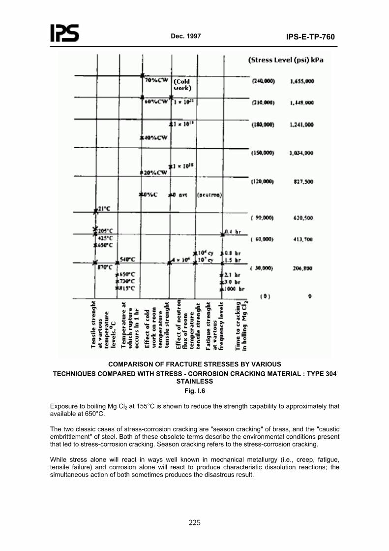
Dec. 1997
IPS-E-TP-760
225
COMPARISON OF FRACTURE STRESSES BY VARIOUS
TECHNIQUES COMPARED WITH STRESS - CORROSION CRACKING MATERIAL : TYPE 304 STAINLESS
Fig. I.6
Exposure to boiling Mg Cl2 at 155°C is shown to reduce the strength capability to approximately that available at 650°C.
The two classic cases of stress-corrosion cracking are "season cracking" of brass, and the "caustic embrittlement" of steel. Both of these obsolete terms describe the environmental conditions present that led to stress-corrosion cracking. Season cracking refers to the stress-corrosion cracking.
While stress alone will react in ways well known in mechanical metallurgy (i.e., creep, fatigue, tensile failure) and corrosion alone will react to produce characteristic dissolution reactions; the simultaneous action of both sometimes produces the disastrous result.
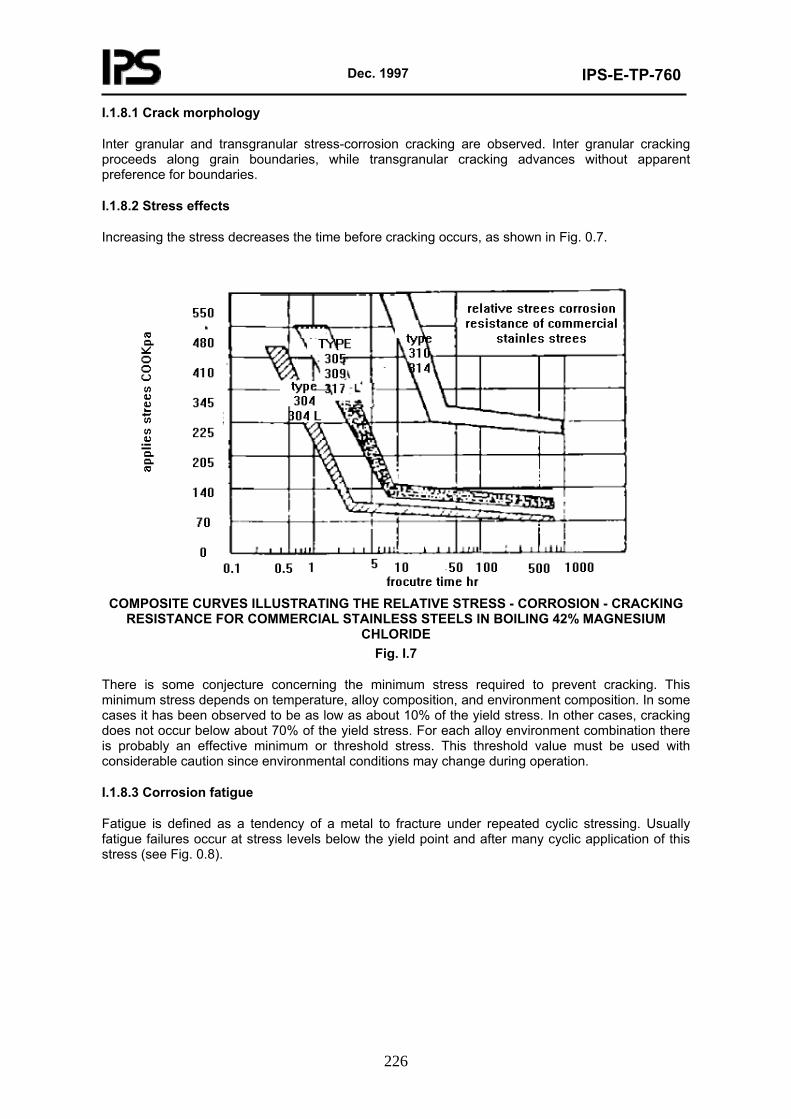
Dec. 1997
IPS-E-TP-760
226
I.1.8.1 Crack morphology
Inter granular and transgranular stress-corrosion cracking are observed. Inter granular cracking proceeds along grain boundaries, while transgranular cracking advances without apparent preference for boundaries.
I.1.8.2 Stress effects
Increasing the stress decreases the time before cracking occurs, as shown in Fig. 0.7.
COMPOSITE CURVES ILLUSTRATING THE RELATIVE STRESS - CORROSION - CRACKING
RESISTANCE FOR COMMERCIAL STAINLESS STEELS IN BOILING 42% MAGNESIUM CHLORIDE
Fig. I.7
There is some conjecture concerning the minimum stress required to prevent cracking. This minimum stress depends on temperature, alloy composition, and environment composition. In some cases it has been observed to be as low as about 10% of the yield stress. In other cases, cracking does not occur below about 70% of the yield stress. For each alloy environment combination there is probably an effective minimum or threshold stress. This threshold value must be used with considerable caution since environmental conditions may change during operation.
I.1.8.3 Corrosion fatigue
Fatigue is defined as a tendency of a metal to fracture under repeated cyclic stressing. Usually fatigue failures occur at stress levels below the yield point and after many cyclic application of this stress (see Fig. 0.8).
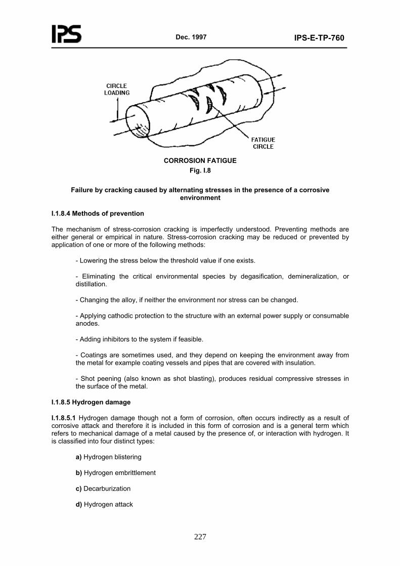
Dec. 1997
IPS-E-TP-760
227
CORROSION FATIGUE
Fig. I.8
Failure by cracking caused by alternating stresses in the presence of a corrosive environment
I.1.8.4 Methods of prevention
The mechanism of stress-corrosion cracking is imperfectly understood. Preventing methods are either general or empirical in nature. Stress-corrosion cracking may be reduced or prevented by application of one or more of the following methods:
- Lowering the stress below the threshold value if one exists.
- Eliminating the critical environmental species by degasification, demineralization, or distillation.
- Changing the alloy, if neither the environment nor stress can be changed.
- Applying cathodic protection to the structure with an external power supply or consumable anodes.
- Adding inhibitors to the system if feasible.
- Coatings are sometimes used, and they depend on keeping the environment away from the metal for example coating vessels and pipes that are covered with insulation.
- Shot peening (also known as shot blasting), produces residual compressive stresses in the surface of the metal.
I.1.8.5 Hydrogen damage
I.1.8.5.1 Hydrogen damage though not a form of corrosion, often occurs indirectly as a result of corrosive attack and therefore it is included in this form of corrosion and is a general term which refers to mechanical damage of a metal caused by the presence of, or interaction with hydrogen. It is classified into four distinct types:
a) Hydrogen blistering
b) Hydrogen embrittlement
c) Decarburization
d) Hydrogen attack
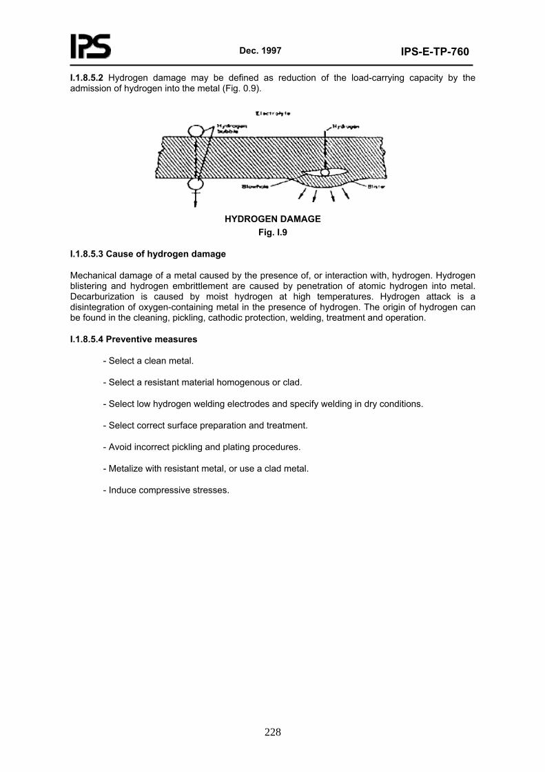
Dec. 1997
IPS-E-TP-760
228
I.1.8.5.2 Hydrogen damage may be defined as reduction of the load-carrying capacity by the admission of hydrogen into the metal (Fig. 0.9).
HYDROGEN DAMAGE
Fig. I.9
I.1.8.5.3 Cause of hydrogen damage
Mechanical damage of a metal caused by the presence of, or interaction with, hydrogen. Hydrogen blistering and hydrogen embrittlement are caused by penetration of atomic hydrogen into metal. Decarburization is caused by moist hydrogen at high temperatures. Hydrogen attack is a disintegration of oxygen-containing metal in the presence of hydrogen. The origin of hydrogen can be found in the cleaning, pickling, cathodic protection, welding, treatment and operation.
I.1.8.5.4 Preventive measures
- Select a clean metal.
- Select a resistant material homogenous or clad.
- Select low hydrogen welding electrodes and specify welding in dry conditions.
- Select correct surface preparation and treatment.
- Avoid incorrect pickling and plating procedures.
- Metalize with resistant metal, or use a clad metal.
- Induce compressive stresses.