Embed Size (px)
Citation preview
ENGLISHFRANÇAISDEUTSCHESPAÑOLITALIANO
13 M 105
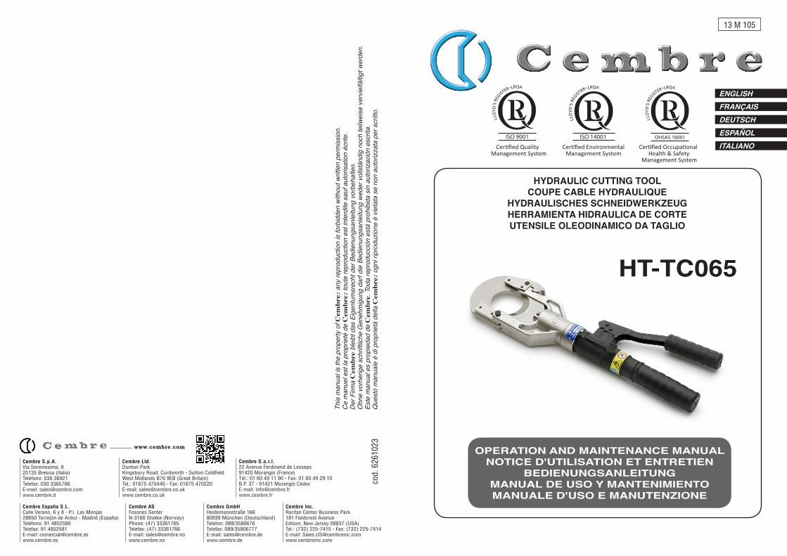
HYDRAULIC CUTTING TOOLCOUPE CABLE HYDRAULIQUE
HYDRAULISCHES SCHNEIDWERKZEUGHERRAMIENTA HIDRAULICA DE CORTEUTENSILE OLEODINAMICO DA TAGLIO
HT-TC065
OPERATION AND MAINTENANCE MANUALNOTICE D'UTILISATION ET ENTRETIEN
BEDIENUNGSANLEITUNGMANUAL DE USO Y MANTENIMIENTOMANUALE D'USO E MANUTENZIONE
cod.
626
1023
This
man
ual is
the
prop
erty
of C
embr
e: a
ny re
prod
uctio
n is
forb
idde
n wi
thou
t writ
ten
perm
issio
n.Ce
man
uel e
st la
pro
prie
té d
e C
embr
e: to
ute
repr
oduc
tion
est i
nter
dite
sau
f aut
orisa
tion
écrit
e.De
r Firm
a C
embr
e bl
eibt
das
Eig
entu
msr
echt
der
Bed
ienu
ngsa
nlei
tung
vor
beha
lten.
Ohn
e vo
rher
ige
schr
iftlic
he G
eneh
mig
ung
darf
die
Bedi
enun
gsan
leitu
ng w
eder
vol
lstän
dig
noch
teilw
eise
ver
vielfä
ltigt w
erde
n.Es
te m
anua
l es
prop
ieda
d de
Cem
bre.
Tod
a re
prod
ucció
n es
tá p
rohi
bida
sin
aut
oriza
ción
escr
ita.
Que
sto
man
uale
è d
i pro
prie
tà d
ella
Cem
bre:
ogn
i rip
rodu
zione
é v
ieta
ta s
e no
n au
toriz
zata
per
scr
itto.
Cembre Ltd.Dunton ParkKingsbury Road, Curdworth - Sutton ColdfieldWest Midlands B76 9EB (Great Britain)Tel.: 01675 470440 - Fax: 01675 470220E-mail: [email protected]
Cembre S.p.A. Via Serenissima, 9 25135 Brescia (Italia) Telefono: 030 36921Telefax: 030 3365766E-mail: [email protected]
Cembre S.a.r.l.22 Avenue Ferdinand de Lesseps91420 Morangis (France)Tél.: 01 60 49 11 90 - Fax: 01 60 49 29 10B.P. 37 - 91421 Morangis CédexE-mail: [email protected]
Cembre España S.L.Calle Verano, 6 y 8 - P.I. Las Monjas28850 Torrejón de Ardoz - Madrid (España)Teléfono: 91 4852580Telefax: 91 4852581E-mail: [email protected]
Cembre ASFossnes SenterN-3160 Stokke (Norway)Phone: (47) 33361765Telefax: (47) 33361766E-mail: [email protected]
Cembre GmbHHeidemannstraße 16680939 München (Deutschland)Telefon: 089/3580676Telefax: 089/35806777E-mail: [email protected]
Cembre Inc.Raritan Center Business Park181 Fieldcrest AvenueEdison, New Jersey 08837 (USA)Tel.: (732) 225-7415 - Fax: (732) 225-7414E-mail: [email protected]
www.cembre.com
Cer�fied EnvironmentalManagement System
Cer�fied Occupa�onalHealth & Safety
Management System
Cer�fied QualityManagement System
1
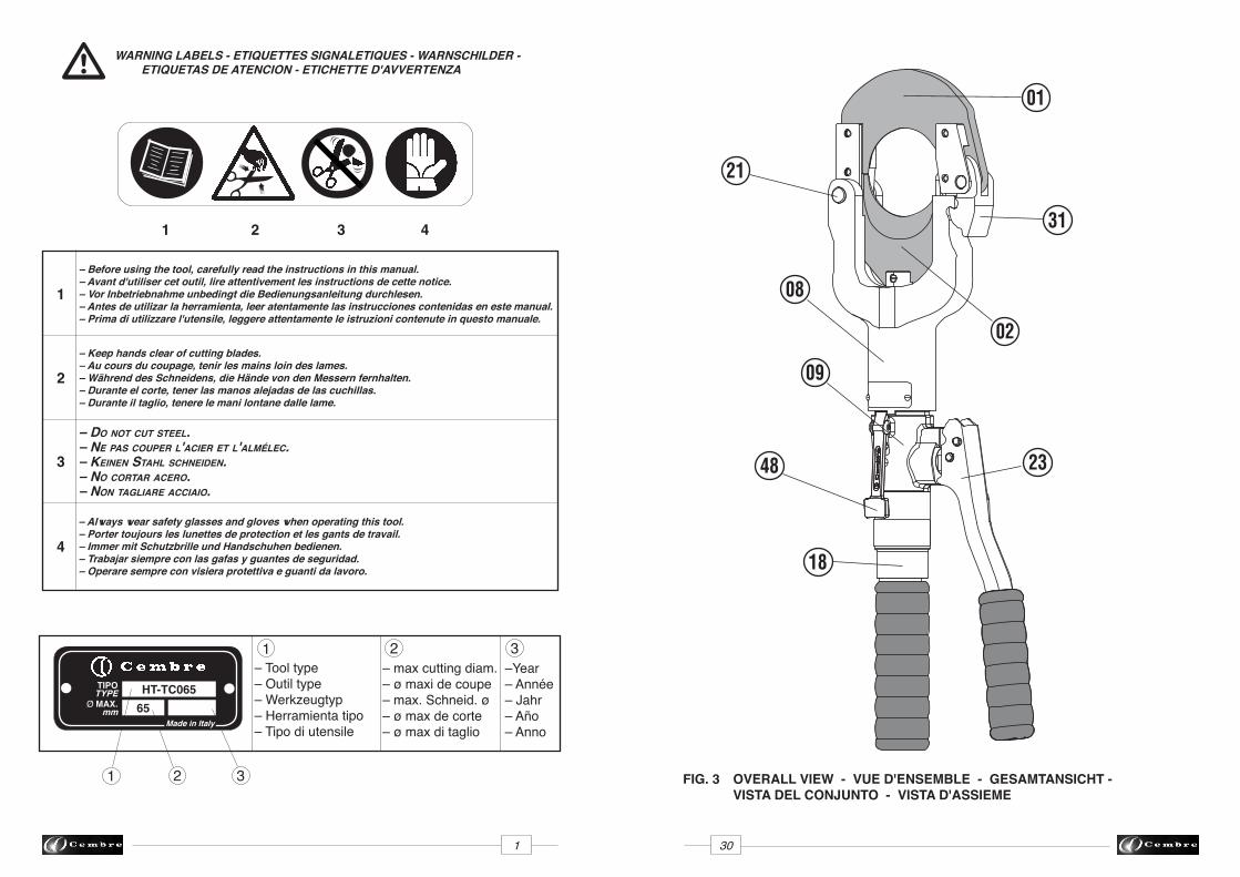
– Tool type– Outil type– Werkzeugtyp– Herramienta tipo– Tipo di utensile
–Year– Année– Jahr– Año– Anno
– Before using the tool, carefully read the instructions in this manual.– Avant d'utiliser cet outil, lire attentivement les instructions de cette notice.– Vor Inbetriebnahme unbedingt die Bedienungsanleitung durchlesen.– Antes de utilizar la herramienta, leer atentamente las instrucciones contenidas en este manual.– Prima di utilizzare l'utensile, leggere attentamente le istruzioni contenute in questo manuale.
– Keep hands clear of cutting blades.– Au cours du coupage, tenir les mains loin des lames.– Während des Schneidens, die Hände von den Messern fernhalten.– Durante el corte, tener las manos alejadas de las cuchillas.– Durante il taglio, tenere le mani lontane dalle lame.
2
– Do not cut steel.– ne pas couper l'acier et l'almélec.– Keinen stahl schneiDen.– no cortar acero.– non tagliare acciaio.
3
TIPOTYPE
Ø MAX.mm 65
HT-TC065
2 3
1 2 3
– Always wear safety glasses and gloves when operating this tool.– Porter toujours les lunettes de protection et les gants de travail.– Immer mit Schutzbrille und Handschuhen bedienen.– Trabajar siempre con las gafas y guantes de seguridad.– Operare sempre con visiera protettiva e guanti da lavoro.
4
1 2 3
1
4
– max cutting diam.– ø maxi de coupe– max. Schneid. ø – ø max de corte– ø max di taglio
WARNING LABELS - ETIQUETTES SIGNALETIQUES - WARNSCHILDER - ETIQUETAS DE ATENCION - ETICHETTE D'AVVERTENZA
✃((
((
➠
➠
1 30
Made in Italy
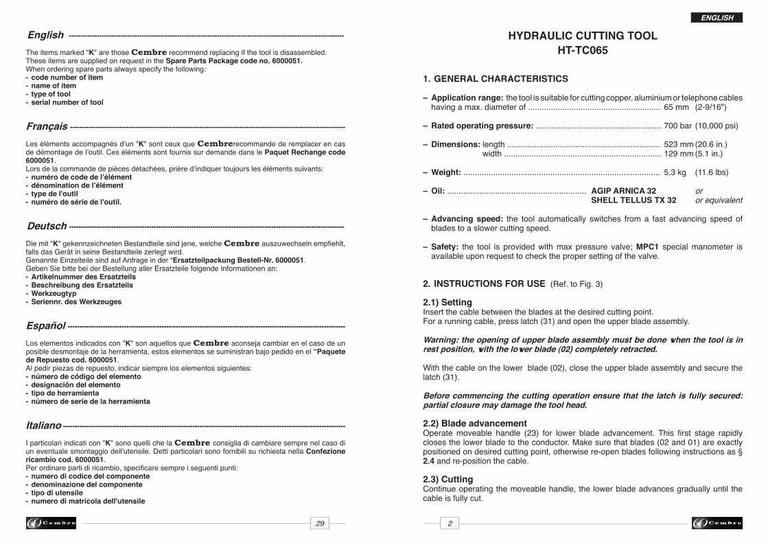
FIG. 3 OVERALL VIEW - VUE D'ENSEMBLE - GESAMTANSICHT - VISTA DEL CONJUNTO - VISTA D'ASSIEME
02
31
01
18
2348
21
09
08
ENGLISH
HYDRAULIC CUTTING TOOLHT-TC065
1. GENERAL CHARACTERISTICS
– Application range: the tool is suitable for cutting copper, aluminium or telephone cables having a max. diameter of .......................................................... 65 mm (2-9/16")
– Rated operating pressure: ....................................................... 700 bar (10,000 psi)
– Dimensions: length ................................................................... 523 mm (20.6 in.) width ..................................................................... 129 mm (5.1 in.)
– Weight: ...................................................................................... 5,3 kg (11.6 lbs)
– Oil: ............................................................. AGIP ARNICA 32 or SHELL TELLUS TX 32 or equivalent
– Advancing speed: the tool automatically switches from a fast advancing speed of blades to a slower cutting speed.
– Safety: the tool is provided with max pressure valve; MPC1 special manometer is available upon request to check the proper setting of the valve.
2. INSTRUCTIONS FOR USE (Ref. to Fig. 3)
2.1) SettingInsert the cable between the blades at the desired cutting point.For a running cable, press latch (31) and open the upper blade assembly.
Warning: the opening of upper blade assembly must be done when the tool is in rest position, with the lower blade (02) completely retracted.
With the cable on the lower blade (02), close the upper blade assembly and secure the latch (31).
Before commencing the cutting operation ensure that the latch is fully secured: partial closure may damage the tool head.
2.2) Blade advancementOperate moveable handle (23) for lower blade advancement. This first stage rapidly closes the lower blade to the conductor. Make sure that blades (02 and 01) are exactly positioned on desired cutting point, otherwise re-open blades following instructions as § 2.4 and re-position the cable.
2.3) CuttingContinue operating the moveable handle, the lower blade advances gradually until the cable is fully cut.
29 2
English ---------------------------------------------------------------------------------------------------------------------The items marked "K" are those Cembre recommend replacing if the tool is disassembled. These items are supplied on request in the Spare Parts Package code no. 6000051.When ordering spare parts always specify the following:- code number of item- name of item- type of tool- serial number of tool
Français ---------------------------------------------------------------------------------------------------------------------Les éléments accompagnés d’un "K" sont ceux que Cembrerecommande de remplacer en cas de démontage de l’outil. Ces éléments sont fournis sur demande dans le Paquet Rechange code 6000051. Lors de la commande de pièces détachées, prière d’indiquer toujours les éléments suivants:- numéro de code de l’élément- dénomination de l’élément- type de l'outil- numéro de série de l'outil.
Deutsch ---------------------------------------------------------------------------------------------------------------------Die mit "K" gekennzeichneten Bestandteile sind jene, welche Cembre auszuwechseln empfiehlt, falls das Gerät in seine Bestandteile zerlegt wird. Genannte Einzelteile sind auf Anfrage in der “Ersatzteilpackung Bestell-Nr. 6000051.Geben Sie bitte bei der Bestellung aller Ersatzteile folgende Informationen an:- Artikelnummer des Ersatzteils- Beschreibung des Ersatzteils- Werkzeugtyp- Seriennr. des Werkzeuges
Español ----------------------------------------------------------------------------------------------------------------------Los elementos indicados con "K" son aquellos que Cembre aconseja cambiar en el caso de un posible desmontaje de la herramienta, estos elementos se suministran bajo pedido en el “Paquete de Repuesto cod. 6000051.Al pedir piezas de repuesto, indicar siempre los elementos siguientes:- número de código del elemento- designación del elemento- tipo de herramienta- número de serie de la herramienta
Italiano ------------------------------------------------------------------------------------------------------------------------
I particolari indicati con "K" sono quelli che la Cembre consiglia di cambiare sempre nel caso di un eventuale smontaggio dell’utensile. Detti particolari sono fornibili su richiesta nella Confezione ricambio cod. 6000051.Per ordinare parti di ricambio, specificare sempre i seguenti punti:- numero di codice del componente- denominazione del componente- tipo di utensile- numero di matricola dell'utensile
ENGLISH
3 28
CANVAS BAG
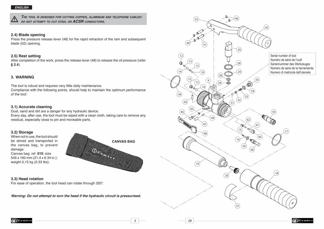
the tool is DesigneD for cutting copper, aluminium anD telephone cables: Do not attempt to cut steel or acsr conDuctors.
2.4) Blade openingPress the pressure release lever (48) for the rapid retraction of the ram and subsequent blade (02) opening.
2.5) Rest settingAfter completion of the work, press the release lever (48) to release the oil pressure (refer § 2.4).
3. WARNING
The tool is robust and requires very little daily maintenance. Compliance with the following points, should help to maintain the optimum performance of the tool:
3.1) Accurate cleaningDust, sand and dirt are a danger for any hydraulic device.Every day, after use, the tool must be wiped with a clean cloth, taking care to remove any residual, especially close to pin and moveable parts.
3.2) Storage When not in use, the tool should be stored and transported in the canvas bag, to prevent damage. Canvas bag: ref. 010; size 545 x 160 mm (21.4 x 6.34 in.); weight 0,15 kg (0.33 lbs).
3.3) Head rotationFor ease of operation, the tool head can rotate through 320°.
Warning: Do not attempt to turn the head if the hydraulic circuit is pressurised.
xxxxxx
60
35
35
13
57
20
58
15
16
62
43
48
49
47
4650
56
9 55
54
5352
51
29
24
26
28
23
4140
40
16
15
14
13
12
14
12
44
39
31
36
2737
38
45
33
4
17
201
19
61
59
8
2
34
21
18
42
25
1
32
11
10
7
200
6
30
8
7
6
Serial number of toolNuméro de série de l’outilSeriennummer des WerkzeugesNúmero de serie de la herramientaNumero di matricola dell’utensile
ENGLISH
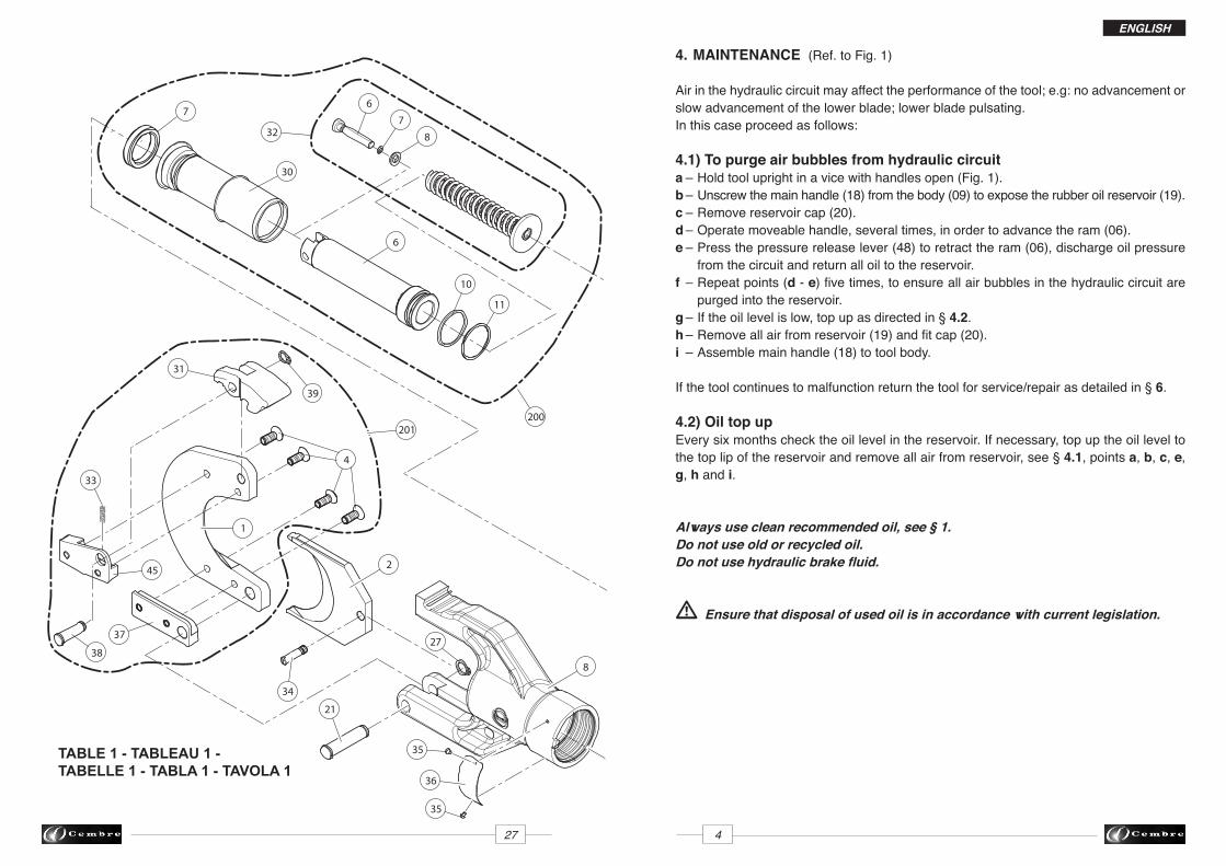
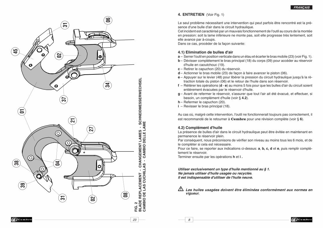
4. MAINTENANCE (Ref. to Fig. 1)
Air in the hydraulic circuit may affect the performance of the tool; e.g: no advancement or slow advancement of the lower blade; lower blade pulsating.In this case proceed as follows:
4.1) To purge air bubbles from hydraulic circuita – Hold tool upright in a vice with handles open (Fig. 1).b – Unscrew the main handle (18) from the body (09) to expose the rubber oil reservoir (19).c – Remove reservoir cap (20).d – Operate moveable handle, several times, in order to advance the ram (06).e – Press the pressure release lever (48) to retract the ram (06), discharge oil pressure from the circuit and return all oil to the reservoir. f – Repeat points (d - e) five times, to ensure all air bubbles in the hydraulic circuit are purged into the reservoir.g – If the oil level is low, top up as directed in § 4.2. h – Remove all air from reservoir (19) and fit cap (20).i – Assemble main handle (18) to tool body.
If the tool continues to malfunction return the tool for service/repair as detailed in § 6.
4.2) Oil top upEvery six months check the oil level in the reservoir. If necessary, top up the oil level to the top lip of the reservoir and remove all air from reservoir, see § 4.1, points a, b, c, e, g, h and i.
Always use clean recommended oil, see § 1.Do not use old or recycled oil.Do not use hydraulic brake fluid.
Ensure that disposal of used oil is in accordance with current legislation.
27 4
TABLE 1 - TABLEAU 1 - TABELLE 1 - TABLA 1 - TAVOLA 1
60
35
35
13
57
20
58
15
16
62
43
48
49
47
4650
56
9 55
54
5352
51
29
24
26
28
23
4140
40
16
15
14
13
12
14
12
44
39
31
36
2737
38
45
33
4
17
201
19
61
59
8
2
34
21
18
42
25
1
32
11
10
7
200
6
30
8
7
6
ENGLISH
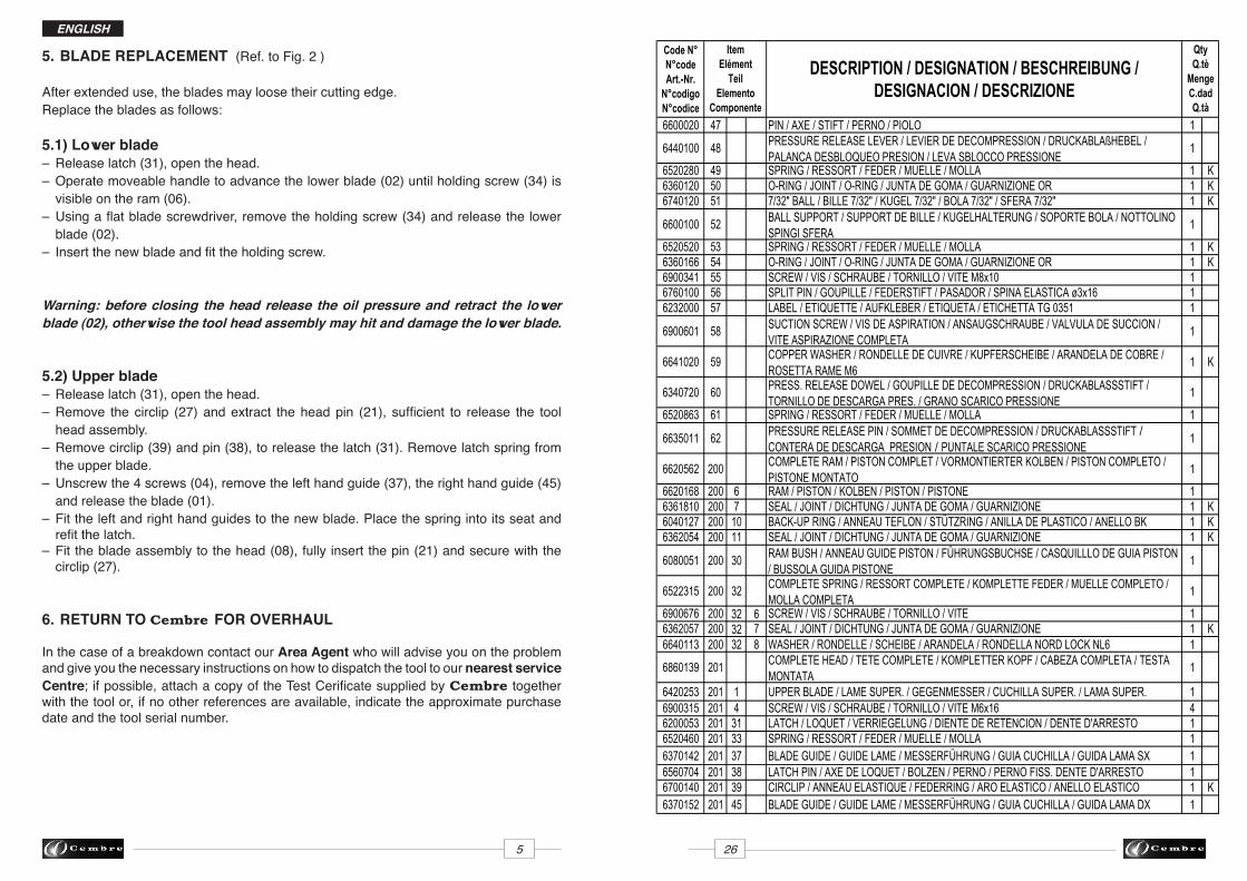
5. BLADE REPLACEMENT (Ref. to Fig. 2 )
After extended use, the blades may loose their cutting edge. Replace the blades as follows:
5.1) Lower blade– Release latch (31), open the head.– Operate moveable handle to advance the lower blade (02) until holding screw (34) is visible on the ram (06).– Using a flat blade screwdriver, remove the holding screw (34) and release the lower blade (02).– Insert the new blade and fit the holding screw.
Warning: before closing the head release the oil pressure and retract the lowerblade (02), otherwise the tool head assembly may hit and damage the lower blade.
5.2) Upper blade – Release latch (31), open the head.– Remove the circlip (27) and extract the head pin (21), sufficient to release the tool head assembly.– Remove circlip (39) and pin (38), to release the latch (31). Remove latch spring from the upper blade.– Unscrew the 4 screws (04), remove the left hand guide (37), the right hand guide (45) and release the blade (01).– Fit the left and right hand guides to the new blade. Place the spring into its seat and refit the latch.– Fit the blade assembly to the head (08), fully insert the pin (21) and secure with the circlip (27).
6. RETURN TO Cembre FOR OVERHAUL
In the case of a breakdown contact our Area Agent who will advise you on the problem and give you the necessary instructions on how to dispatch the tool to our nearest service Centre; if possible, attach a copy of the Test Cerificate supplied by Cembre together with the tool or, if no other references are available, indicate the approximate purchase date and the tool serial number.
5 26
Code N° N°codeArt.-Nr.
N°codigoN°codice
DESCRIPTION / DESIGNATION / BESCHREIBUNG / DESIGNACION / DESCRIZIONE
6600020 47 PIN / AXE / STIFT / PERNO / PIOLO 1
6440100 48 PRESSURE RELEASE LEVER / LEVIER DE DECOMPRESSION / DRUCKABLAßHEBEL / PALANCA DESBLOQUEO PRESION / LEVA SBLOCCO PRESSIONE
1
6520280 49 SPRING / RESSORT / FEDER / MUELLE / MOLLA 1 K6360120 50 O-RING / JOINT / O-RING / JUNTA DE GOMA / GUARNIZIONE OR 1 K6740120 51 7/32" BALL / BILLE 7/32" / KUGEL 7/32" / BOLA 7/32" / SFERA 7/32" 1 K
6600100 52 BALL SUPPORT / SUPPORT DE BILLE / KUGELHALTERUNG / SOPORTE BOLA / NOTTOLINO SPINGI SFERA
1
6520520 53 SPRING / RESSORT / FEDER / MUELLE / MOLLA 1 K6360166 54 O-RING / JOINT / O-RING / JUNTA DE GOMA / GUARNIZIONE OR 1 K6900341 55 SCREW / VIS / SCHRAUBE / TORNILLO / VITE M8x10 16760100 56 SPLIT PIN / GOUPILLE / FEDERSTIFT / PASADOR / SPINA ELASTICA ø3x16 16232000 57 LABEL / ETIQUETTE / AUFKLEBER / ETIQUETA / ETICHETTA TG 0351 1
6900601 58 SUCTION SCREW / VIS DE ASPIRATION / ANSAUGSCHRAUBE / VALVULA DE SUCCION / VITE ASPIRAZIONE COMPLETA
1
6641020 59 COPPER WASHER / RONDELLE DE CUIVRE / KUPFERSCHEIBE / ARANDELA DE COBRE / ROSETTA RAME M6
1 K
6340720 60 PRESS. RELEASE DOWEL / GOUPILLE DE DECOMPRESSION / DRUCKABLASSSTIFT / TORNILLO DE DESCARGA PRES. / GRANO SCARICO PRESSIONE
1
6520863 61 SPRING / RESSORT / FEDER / MUELLE / MOLLA 1
6635011 62 PRESSURE RELEASE PIN / SOMMET DE DECOMPRESSION / DRUCKABLASSSTIFT / CONTERA DE DESCARGA PRESION / PUNTALE SCARICO PRESSIONE
1
6620562 200 COMPLETE RAM / PISTON COMPLET / VORMONTIERTER KOLBEN / PISTON COMPLETO / PISTONE MONTATO
1
6620168 200 6 RAM / PISTON / KOLBEN / PISTON / PISTONE 16361810 200 7 SEAL / JOINT / DICHTUNG / JUNTA DE GOMA / GUARNIZIONE 1 K6040127 200 10 BACK-UP RING / ANNEAU TEFLON / STÜTZRING / ANILLA DE PLASTICO / ANELLO BK 1 K6362054 200 11 SEAL / JOINT / DICHTUNG / JUNTA DE GOMA / GUARNIZIONE 1 K
6080051 200 30 RAM BUSH / ANNEAU GUIDE PISTON / FÜHRUNGSBUCHSE / CASQUILLLO DE GUIA PISTON / BUSSOLA GUIDA PISTONE
1
6522315 200 32 COMPLETE SPRING / RESSORT COMPLETE / KOMPLETTE FEDER / MUELLE COMPLETO / MOLLA COMPLETA
1
6900676 200 32 6 SCREW / VIS / SCHRAUBE / TORNILLO / VITE 16362057 200 32 7 SEAL / JOINT / DICHTUNG / JUNTA DE GOMA / GUARNIZIONE 1 K6640113 200 32 8 WASHER / RONDELLE / SCHEIBE / ARANDELA / RONDELLA NORD LOCK NL6 1
6860139 201 COMPLETE HEAD / TETE COMPLETE / KOMPLETTER KOPF / CABEZA COMPLETA / TESTA MONTATA
1
6420253 201 1 UPPER BLADE / LAME SUPER. / GEGENMESSER / CUCHILLA SUPER. / LAMA SUPER. 16900315 201 4 SCREW / VIS / SCHRAUBE / TORNILLO / VITE M6x16 46200053 201 31 LATCH / LOQUET / VERRIEGELUNG / DIENTE DE RETENCION / DENTE D'ARRESTO 16520460 201 33 SPRING / RESSORT / FEDER / MUELLE / MOLLA 16370142 201 37 BLADE GUIDE / GUIDE LAME / MESSERFÜHRUNG / GUIA CUCHILLA / GUIDA LAMA SX 16560704 201 38 LATCH PIN / AXE DE LOQUET / BOLZEN / PERNO / PERNO FISS. DENTE D'ARRESTO 16700140 201 39 CIRCLIP / ANNEAU ELASTIQUE / FEDERRING / ARO ELASTICO / ANELLO ELASTICO 1 K6370152 201 45 BLADE GUIDE / GUIDE LAME / MESSERFÜHRUNG / GUIA CUCHILLA / GUIDA LAMA DX 1
QtyQ.tè
MengeC.dadQ.tà
ItemElément
TeilElemento
Componente
25 6
FRANÇAIS
COUPE-CABLE HYDRAULIQUETYPE HT-TC065
1. CARACTERISTIQUES GENERALES
– Domaine d'application: conçu pour sectionner des câbles en cuivre ou aluminium ou téléphoniques d'un diamètre extérieur maximum de .................. 65 mm (2-9/16") – Pression nominale: .................................................................. 700 bar (10,000 psi)
– Dimensions: hauteur ................................................................ 523 mm (20.6 in.) largeur ................................................................. 129 mm (5.1 in.)
– Poids: ......................................................................................... 5,3 kg (11.6 lbs)
– Huile: .......................................................... AGIP ARNICA 32 ou SHELL TELLUS TX 32 ou équivalent
– Avance rapide: l'outil passe automatiquement de la vitesse rapide d'approche des lames, à la vitesse lente de coupe.
– Sécurité: l'outil est pourvu d'une valve de surpression. Pour vérifier le bon fonctionnement de cette valve, un manomètre spécial, réf. MPC1, est disponible à la demande.
2. INSTRUCTIONS D'UTILISATION (Voir Fig. 3)
2.1) Mise en servicePositionner le conducteur entre les lames de l'outil à l'endroit souhaité pour la coupe.Si le câble est passant, il sera alors nécessaire de tirer le loquet (31) de façon à ouvrir la tête (lame supérieure).
Attention: ne jamais ouvrir la tête du coupe-câble tant que la lame inférieure (02) n'est pas complètement descendue.
Positionner le câble sur la lame inférieure, et refermer la tête à l'aide du loquet (31).
Avant de procéder à la coupe, s'assurer que le loquet (31) soit parfaitement en-clenché.
2.2) Avance des lamesEn actionnant le bras mobile (23), le piston se déplace en vitesse rapide jusqu'à ce que les lames (02 et 01) soient en contact avec le conducteur. Si la position de coupe n'est pas bonne, desserrer les lames (voir § 2.4) et repositionner le câble.
2.3) CoupeEn poursuivant la manœuvre du bras mobile, la lame inférieure monte jusqu'à ce que le conducteur soit complètement sectionné.
The guarantee is void if parts used are not Cembre original spares.La garantie perd tout effet en cas d’emploi de piéces détachées différentes des pièces d’origine Cembre.
Die Garantie verfällt, wenn nicht Originalteile aus dem Hause Cembre in das Gerät eingebaut werden.La garantía pierde su valor si se utilizan piezas de repuesto distintas de las originales Cembre.
La garanzia decade qualora vengano utilizzate parti di ricambio non originali Cembre.
TABLE 1 - TABLEAU 1 - TABELLE 1 - TABLA 1 - TAVOLA 1
Code N° N°codeArt.-Nr.
N°codigoN°codice
DESCRIPTION / DESIGNATION / BESCHREIBUNG / DESIGNACION / DESCRIZIONE
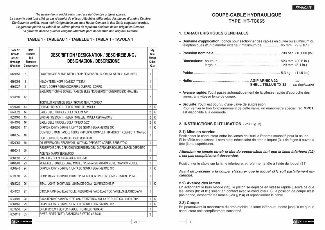
6420150 2 LOWER BLADE / LAME INFER. / SCHNEIDMESSER / CUCHILLA INFER. / LAMA INFER. 1
6860098 8 HEAD / TETE / KOPF / CABEZA / TESTA 1
6160027 9 BODY / CORPS / GRUNDKÖRPER / CUERPO / CORPO 1
6340590 12
BALL POSITIONING DOWEL / AXE DE BILLE / KUGELPOSITIONIERUNGSSCHRAUBE /
TORNILLO RETEN DE BOLA / GRANO TENUTA SFERA
2
6520200 13 SPRING / RESSORT / FEDER / MUELLE / MOLLA 2 K
6740020 14 BALL / BILLE / KUGEL / BOLA / SFERA 1/4" 2 K
6520160 15 SPRING / RESSORT / FEDER / MUELLE / MOLLA ASPIRAZIONE 2 K
6740100 16 BALL / BILLE / KUGEL / BOLA / SFERA 5/32" 2 K
6360250 17 O-RING / JOINT / O-RING / JUNTA DE GOMA / GUARNIZIONE OR 1 K
6480055 18COMPLETE MAIN HANDLE / BRAS PRINCIPAL COMPLET / HANDGRIFF KOMPLETT / MANGO
FIJO COMPLETO / MANICO FISSO MONTATO1
6720050 19 OIL RESERVOIR / RESERVOIR / ÖLTANK / DEPOSITO ACEITE / SERBATOIO 1
6800040 20RESERVOIR CAP / CAPUCHON DE RESERVOIR / ÖLTANKVERSCHLUß / TAPON DEPOSITO
ACEITE / TAPPO SERBATOIO1
6560691 21 PIN / AXE / BOLZEN / PASADOR / PERNO 1
6480909 23 MOVEABLE HANDLE / BRAS MOBILE / PUMPARM / MANGO MOVIL / MANICO MOBILE 1
6360240 24 O-RING / JOINT / O-RING / JUNTA DE GOMA / GUARNIZIONE OR 1 K
6620090 25 PUMP. RAM / PISTON DE POMP. / PUMPKOLBEN / PISTON BOMB. / PISTONE POMP. 1
6362020 26 SEAL / JOINT / DICHTUNG / JUNTA DE GOMA / GUARNIZIONE JF 1 K
6040421 27 CIRCLIP / ANNEAU ELASTIQUE / FEDERRING / ARO ELASTICO / ANELLO ELASTICO ø10 1
6040101 28 BACK-UP RING / ANNEAU TEFLON / STÜTZRING / ANILLA DE PLASTICO / ANELLO BK 1 K
6360161 29 O-RING / JOINT / O-RING / JUNTA DE GOMA / GUARNIZIONE OR 1 K
6370250 34 GRUB SCREW / VIS / SCHRAUBE / TORNILLO / GRANO 1
6650118 35 RIVET / RIVET / NIET / PASADOR / RIVETTO ø2,5x3,5 2
6232512 36 METAL LABEL / PLAQUETTE / TYPENSCHILD / TARJETA / TARGHETTA TG 0721 1
6700060 40 CIRCLIP / ANNEAU ELASTIQUE / FEDERRING / ARO ELASTICO / ANELLO ELASTICO 4 K
6560262 41 PIN / AXE / BOLZEN / PERNO / PERNO 2
6380200 42 HANDLE GRIP / POIGNEE / HANDGRIFF / EMPUÑADURA MANGO / IMPUGN. MANICO 1
6895046 43MAX PRESSURE VALVE / VALVE DE SURPRESSION / ÜBERDRUCKVENTIL / VALVULA
COMPLETA / VALVOLA COMPLETA1
6360266 44 O-RING / JOINT / O-RING / JUNTA DE GOMA / GUARNIZIONE OR 1 K
6020027 46PRESSURE RELEASE PIN / PISTON DE DECOMPRESSION / DRUCKABLAßHEBEL /
PISTONCILLO DESBLOQ. PRESION / PISTONCINO SCARICO PRESSIONE1
QtyQ.tè
MengeC.dadQ.tà
ItemElément
TeilElemento
Componente
FRANÇAIS
7 24
SACOCHE
cet outil n'a été conçu que pour couper Des câbles en cuivre, en aluminium et telephoniques. ne Doit jamais être utilisé sur Des conDucteurs en acier ou en aluminium-acier.
2.4) Réouverture des lamesAppuyer sur le levier (48), situé sur le corps afin d'activer la valve de décompression et permettre le retour de la lame inférieure dans sa position de repos.
2.5) RangementAprès l'utilisation, l'outil doit être ramené dans sa position de repos (voir § 2.4), et rangé dans son coffret.
3. PRECAUTIONS
Cet outil est robuste et ne nécessite aucun entretien particulier.Les recommandations suivantes sont néanmoins souhaitables pour lui assurer une lon-gévité optimum:
3.1) Nettoyage élémentaireVeiller à toujours protéger l'outil de la poussière, du sable et de la boue qui représentent un danger pour tout système hydraulique. Chaque jour, après utilisation, il doit être nettoyé avec un chiffon propre, tout particulièrement aux endroit des pièces mobiles.
3.2) Rangement Afin d'éviter les chocs et la pous-sière, il est de bonne règle de ranger l'outil dans sa sacoche après usage.Cette sacoche (type 010) a pour dimensions 515 x 150 mm (20.2x6 in.) et un poids de 0,15 kg (0.33 lbs).
3.3) Rotation de la têteLa tête de ce coupe-câble pivote à 320°, permettant à l'utilisateur de toujours travailler dans les meilleures conditions.
Attention: ne jamais forcer la rotation de la tête lorsque le circuit hydraulique est sous pression.
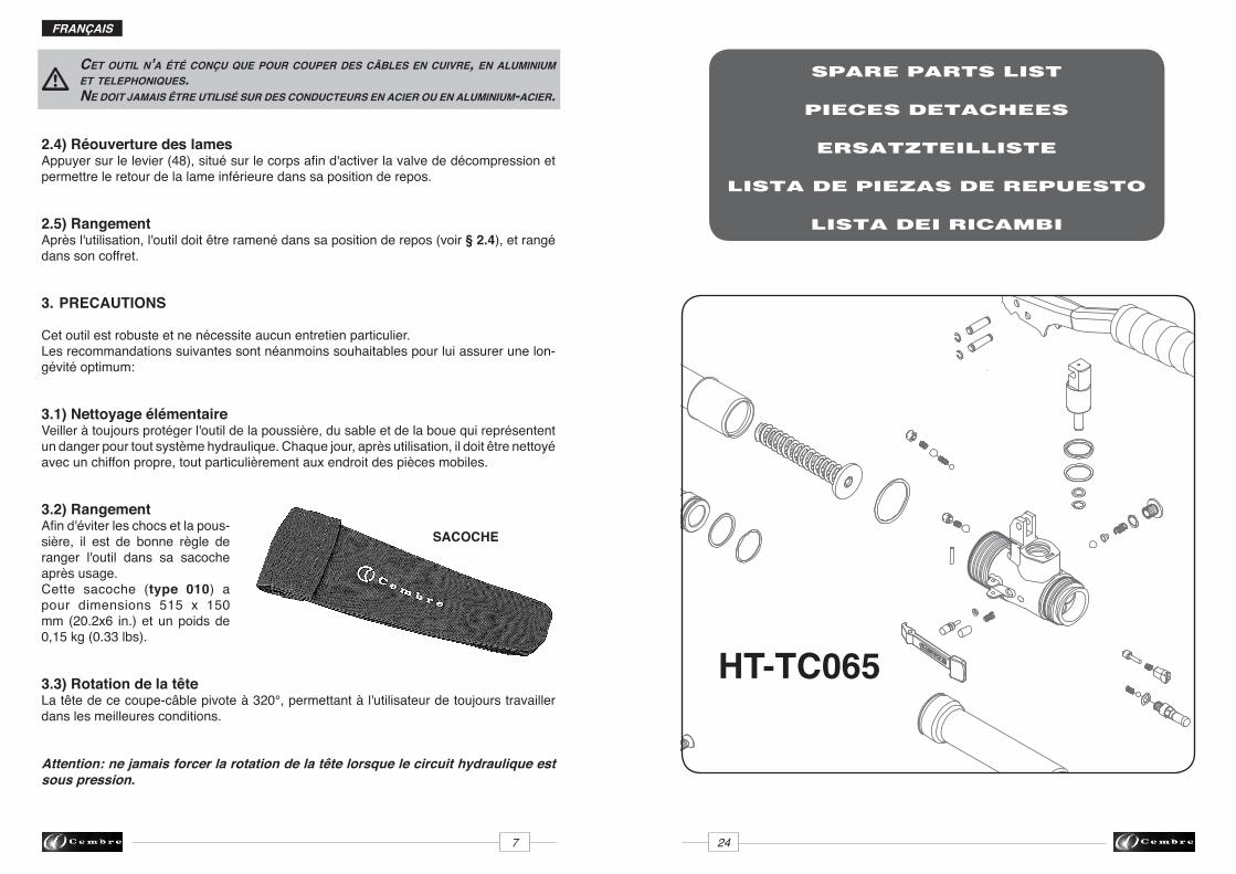
SPARE PARTS LIST
PIECES DETACHEES
ERSATZTEILLISTE
LISTA DE PIEZAS DE REPUESTO
LISTA DEI RICAMBI
HT-TC065
FRANÇAIS
23 8
4. ENTRETIEN (Voir Fig. 1)
Le seul problème nécessitant une intervention qui peut parfois être rencontré est la pré-sence d'une bulle d'air dans le circuit hydraulique.Cet incident est caractérisé par un mauvais fonctionnement de l'outil au cours de la montée en pression: soit la lame inférieure ne monte pas, soit elle progresse très lentement, soit elle avance par à-coups.Dans ce cas, procéder de la façon suivante:
4.1) Elimination de bulles d'aira – Serrer l'outil en position verticale dans un étau et écarter le bras mobile (23) (voir Fig. 1).b – Dévisser complètement le bras principal (18) du corps (09) pour accéder au réservoir d'huile en caoutchouc (19).c – Retirer le capuchon (20) du réservoir.d – Actionner le bras mobile (23) de façon à faire avancer le piston (06).e – Appuyer sur le levier (48) pour libérer la pression du circuit hydraulique jusqu'à la rè- traction totale du piston (06) et le retour de l'huile dans son réservoir.f – Réitérer les opérations (d - e) au moins 5 fois pour que les bulles d'air du circuit soient entièrement évacuées par le réservoir d'huile.g – Avant de refermer le réservoir, s'assurer que tout l'air ait été évacué, et effectuer, si besoin, un complément d'huile (voir § 4.2).h – Refermer le capuchon (20).i – Revisser le bras principal (18).
Au cas où, malgré cette intervention, l'outil ne fonctionnerait toujours pas correctement, il est recommandé de le retourner à Cembre pour une révision complète (voir § 6).
4.2) Complément d'huileLa présence de bulles d'air dans le circuit hydraulique peut être évitée en maintenant en permanence le réservoir plein.Par conséquent, nous préconisons de vérifier son niveau au moins tous les 6 mois, et de le compléter si cela est nécessaire.Pour ce faire, se reporter aux indications ci-dessus: a, b, c, d et e, puis remplir complè-tement le réservoir.Terminer ensuite par les opérations h et i .
Utiliser exclusivement un type d'huile mentionné au § 1.Ne jamais utiliser d'huile usagée ou recyclée. Il est indispensable d'utiliser de l'huile neuve.
Les huiles usagées doivent être éliminées conformément aux normes en vigueur.
FIG
. 2B
LAD
E R
EPLA
CEM
ENT
- C
HA
NG
EMEN
T LA
MES
- S
CH
NEI
DM
ESSE
RWEC
HSE
LC
AM
BIO
DE
LAS
CU
CH
ILLA
S -
CA
MB
IO D
ELLE
LA
ME
3104
21
27
01
34
45
37
39
02
08
06
38
31
02
FRANÇAIS
9 22
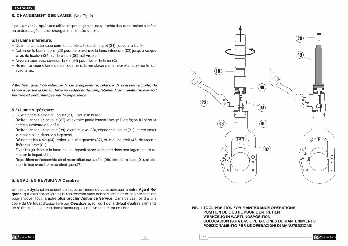
5. CHANGEMENT DES LAMES (Voir Fig. 2)
Il peut arriver qu' après une utilisation prolongée ou inappropriée des lames soient élimées ou endommagées. Leur changement est très simple:
5.1) Lame inférieure:– Ouvrir la la partie supérieure de la tête à l'aide du loquet (31), jusqu’à la butée. – Actionner le bras mobile (23) pour faire avancer la lame inférieure (02) jusqu’à ce que la vis de fixation (34) sur le piston (06) soit visible.– Avec un tournevis, dévisser la vis (34) pour libérer la lame (02). – Retirer l'ancienne lame de son logement, la remplacer par la nouvelle, et serrer le tout avec la vis.
Attention: avant de refermer la lame supérieure, relâcher la pression d’huile, de façon à ce que la lame inférieure redescende complètement, pour éviter qu’elle soit heurtée et endommagée par la supérieure.
5.2) Lame supérieure:– Ouvrir la tête à l'aide du loquet (31) jusqu'à la butée.– Retirer l’anneau élastique (27), et extraire partiellement l'axe (21) de façon à libérer la partie supérieure de la tête.– Retirer l’anneau élastique (39), extraire l'axe (38), dégager le loquet (31), et récupérer le ressort situé dans son logement.– Démonter les 4 vis (04), retirer le guide gauche (37), et le guide droit (45) de façon à libérer la lame (01).– Fixer les guides sur la lame neuve, repositionner le ressort dans son logement, et re- monter le loquet (31).– Repositionner l'ensemble ainsi reconstitué sur la tête (08), introduire l'axe (21), et blo- quer le tout avec l'anneau élastique (27).
6. ENVOI EN REVISION A Cembre
En cas de dysfonctionnement de l'appareil, merci de vous adresser à notre Agent Ré-gional qui vous conseillera et le cas échéant vous donnera les instructions nécessaires pour envoyer l'outil à notre plus proche Centre de Service. Dans ce cas, joindre une copie du Certificat d'Essai livré par Cembre avec l'outil ou, à défaut d'autres éléments de référence, indiquer la date d'achat approximative et numéro de série.
20
19
09
18
06
02
08
23
FIG. 1 TOOL POSITION FOR MAINTENANCE OPERATIONS POSITION DE L'OUTIL POUR L'ENTRETIEN WERKZEUG IN WARTUNGSPOSITION COLOCACION PARA LAS OPERACIONES DE MANTENIMIENTO POSIZIONAMENTO PER LE OPERAZIONI DI MANUTENZIONE
48
21 10
DEUTSCH
HYDRAULISCHES SCHNEIDWERKZEUGTYP HT-TC065
1. ALLGEMEINE EIGENSCHAFTEN
– Anwendungsbereich: Geeignet zum Schneiden von Kupfer-, Aluminium- und Tele- fonkabeln mit einem max. Durchmesser von ............................. 65 mm (2-9/16")
– Arbeitsdruck: ............................................................................ 700 bar (10,000 psi)
– Abmasse: Länge ....................................................................... 523 mm (20.6 in.) Breite ........................................................................ 129 mm (5.1 in.)
– Gewicht: ..................................................................................... 5,3 kg (11.6 lbs)
– Hydrauliköl: ............................................... AGIP ARNICA 32 oder SHELL TELLUS TX 32 oder ähnlich
– Eilvorschub. Das Werkzeug ist mit einer Doppelkolbenhydraulik ausgerüstet, die an- fangs ein schnelles Zusammenfahren der Schneidmesser ermöglicht und dann auto- matisch auf den langsameren Arbeitshub umschaltet.
– Sicherheit. Das Werkzeug ist mit einem Überdruckventil ausgestattet. Der Arbeit sdruck kann mit dem Kontrollgerät MPC1, das auf Anfrage lieferbar ist, gemessen werden.
2. BEDIENUNGSHINWEISE (Siehe Bild 3)
2.1) VorbereitungDen zu schneidenden Leiter zwischen den Schneidmessern positionieren. Bei einem durchgehenden Leiter muß das Gegenmesser durch Betätigen der Verriegelung (31) geöffnet werden, so daß sich der Befestigungsbolzen (21) dreht.
Achtung: Die öffnung des Gegenmessers darf nur mit ganz zurückgefahrenem Schneidmesser (02) erfolgen.
Das Kabel an das Schneidmesser (02) anlegen und das Gegenmesser mit der Verriege-lung (31) schließen.
Vor dem Schneiden kontrollieren, daß die Verriegelung (31) einwandfrei eingerastet ist.
2.2) SchneidvorgangDurch die Bewegung des Pumparmes (23) fährt das Schneidmesser schnell vor und nähert sich dem Kabel. Kontrollieren Sie, ob sich die Schneidmesser (01 und 02) an der gewünschten Position anliegen. Bei Bedarf können die Messer wieder wie unter Pkt. 2.4 beschrieben neu positioniert werden.
2.3) SchneidenDen Pumparm gleichmäßig betätigen um ein konstantes Vorfahren des Schneidmessers zu erreichen bis das Kabel geschnitten ist.
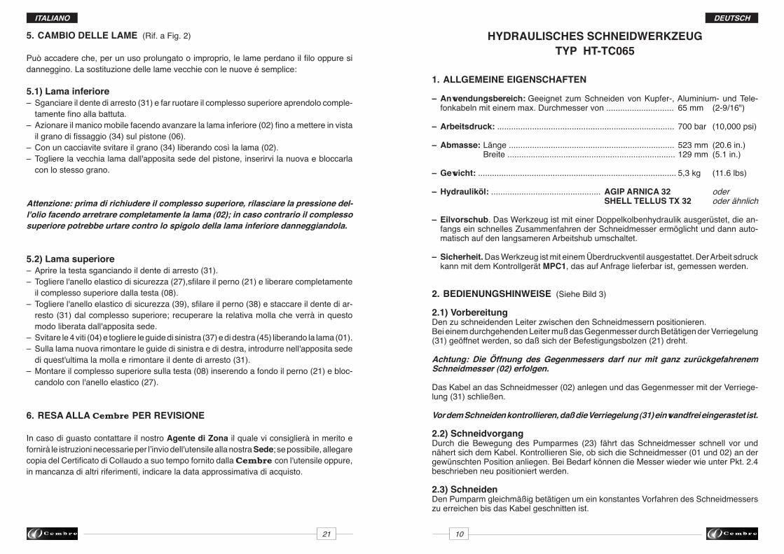
5. CAMBIO DELLE LAME (Rif. a Fig. 2)
Può accadere che, per un uso prolungato o improprio, le lame perdano il filo oppure si danneggino. La sostituzione delle lame vecchie con le nuove é semplice:
5.1) Lama inferiore – Sganciare il dente di arresto (31) e far ruotare il complesso superiore aprendolo comple- tamente fino alla battuta.– Azionare il manico mobile facendo avanzare la lama inferiore (02) fino a mettere in vista il grano di fissaggio (34) sul pistone (06).– Con un cacciavite svitare il grano (34) liberando così la lama (02).– Togliere la vecchia lama dall'apposita sede del pistone, inserirvi la nuova e bloccarla con lo stesso grano.
Attenzione: prima di richiudere il complesso superiore, rilasciare la pressione del-l'olio facendo arretrare completamente la lama (02); in caso contrario il complesso superiore potrebbe urtare contro lo spigolo della lama inferiore danneggiandola.
5.2) Lama superiore – Aprire la testa sganciando il dente di arresto (31).– Togliere l'anello elastico di sicurezza (27),sfilare il perno (21) e liberare completamente il complesso superiore dalla testa (08).– Togliere l'anello elastico di sicurezza (39), sfilare il perno (38) e staccare il dente di ar- resto (31) dal complesso superiore; recuperare la relativa molla che verrà in questo modo liberata dall'apposita sede.– Svitare le 4 viti (04) e togliere le guide di sinistra (37) e di destra (45) liberando la lama (01).– Sulla lama nuova rimontare le guide di sinistra e di destra, introdurre nell'apposita sede di quest'ultima la molla e rimontare il dente di arresto (31).– Montare il complesso superiore sulla testa (08) inserendo a fondo il perno (21) e bloc- candolo con l'anello elastico (27).
6. RESA ALLA Cembre PER REVISIONE
In caso di guasto contattare il nostro Agente di Zona il quale vi consiglierà in merito e fornirà le istruzioni necessarie per l’invio dell'utensile alla nostra Sede; se possibile, allegare copia del Certificato di Collaudo a suo tempo fornito dalla Cembre con l'utensile oppure, in mancanza di altri riferimenti, indicare la data approssimativa di acquisto.
ITALIANO
11 20
DEUTSCH
SEGELTUCHTASCHE
Das WerKzeug ist zum schneiDen von Kupfer-, alluminium unD telefonKabeln geeignet. niemals stahlseile oDer alumunium-stahl seile schneiDen.
2.4) Zurückfahren des Schneidmesser Durch das Betätigen des Druckablaßhebels (48) fährt der Kolben mit dem Schneidmesser zurück.
2.5) NachbereitungDas Werkzeug sollte nach Beendigung der Arbeit in die Ausgangsposition gebracht und in die Segeltuchtasche gelegt werden. Der Druck muß vorher vollständig abgelassen sein (Druckablaßhebel (48) betätigen) siehe § 2.4.
3. HINWEISE
Das Werkzeug ist robust und benötigt keine spezielle Pflege oder Instandhaltung. Zur Erhaltung der Garantieansprüche beachten Sie folgende Hinweise:
3.1) Pflege Dieses hydraulische Werkzeug sollte vor starker Verschmutzung geschützt werden, da diese für ein hydraulisches System gefährlich ist. Jeden Tag nach der Arbeit sollte das Werkzeug mit einem Tuch von Schmutz und Staub gereinigt werden; besonders die beweglichen Teile.
3.2) LagerungWenn das Werkzeug nicht benötigt wird, sollte es in der Segeltuchta-sche gelagert werden und ist somit gegen Beschädigungen wie Stoß und Staub geschützt.Die Segeltuchtasche (Typ 010) hat die Abmasse 515x 150 mm (20.2x6 in.) und ein Gewicht von 0,15 kg (0.33 lbs).
3.3) Drehbewegung des KopfesDas Werkzeug ist mit einem Kopf ausgerüstet, der um 320° drehbar ist und somit ein komfortables Arbeiten ermöglicht.
Der Kopf sollte nicht unter Druck stehend gedreht werden.
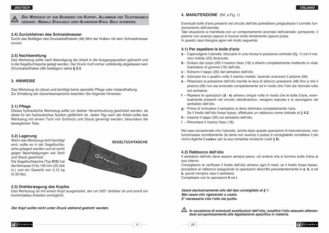
4. MANUTENZIONE (Rif. a Fig. 1)
Eventuali bolle d'aria presenti nel circuito dell'olio potrebbero pregiudicare il corretto fun-zionamento dell'utensile.Tale situazione si manifesta con un comportamento anomalo dell'utensile: pompando, il pistone non avanza oppure si muove molto lentamente oppure pulsa.In questo caso bisogna agire nel modo seguente:
4.1) Per espellere le bolle d'ariaa – Capovolgere l’utensile, bloccarlo in una morsa in posizione verticale (fig. 1) con il ma- nico mobile (23) divaricato.b – Svitare dal corpo (09) il manico fisso (18) e sfilarlo completamente mettendo in vista il serbatoio di gomma (19) dell’olio.c – Estrarre il tappo (20) dal serbatoio dell’olio.d – Azionare tre o quattro volte il manico mobile, facendo avanzare il pistone (06). e – Rilasciare la pressione dell’olio tramite la leva di sblocco pressione (48) fino a che il pistone (06) non sia arretratto completamente ed in modo che l’olio sia ritornato tutto nel serbatoio.f – Ripetere le operazioni (d - e) almeno cinque volte in modo che le bolle d’aria, even- tualmente presenti nel circuito oleodinamico, vengano espulse e si raccolgano nel serbatoio dell’olio.g – Prima di richiudere il serbatoio si deve eliminare completamente l’aria. Se il livello dell’olio fosse basso, effettuare un rabbocco come indicato al § 4.2. h – Inserire il tappo (20) sul serbatoio dell’olio.i – Rimontare il manico fisso (18).
Nel caso eccezionale che l’utensile, anche dopo queste operazioni di manutenzione, non funzionasse correttamente (la lama non avanza o pulsa) è consigliabile contattare il più vicino Agente Cembre per la sua completa revisione (vedi § 6).
4.2) Rabbocco dell'olioIl serbatoio dell'olio deve essere sempre pieno; ciò eviterà che si formino bolle d'aria al suo interno. Consigliamo di verificare il livello dell'olio almeno ogni 6 mesi; se il livello fosse basso, procedere al rabbocco eseguendo le operazioni descritte precedentemente in a, b, c ed e, quindi riempire raso il serbatoio.Completare con le operazioni h ed i.
Usare esclusivamente olio del tipo consigliato al § 1.Mai usare olio rigenerato o usato.E' necessario che l'olio sia pulito.
In occasione di eventuali sostituzioni dell'olio, smaltire l'olio esausto attenen- dosi scrupolosamente alla legislazione specifica in materia.
ITALIANO
DEUTSCH
19 12
4. WARTUNG (Siehe Bild 1)
Befindet sich Luft im Hydrauliksystem, kann es zum fehlerhaften Arbeiten des Werkzeuges kommen. Dies zeigt sich in ungewöhnlichem Verhalten des Werkzeuges. Bei Pumpbeginn bewegt sich das untere Schneidmesser nicht oder nur sehr langsam bzw. stossweise. Ist dies der Fall, sind die folgenden Hinweise zu beachten:
4.1) Entlüftena – Werkzeug mit dem Kopf nach unten (Bild 1) positionieren. Dabei muss der Pumparm (23) in der Öffnungsstellung sein.b – Handgriff (18) aufschrauben und vom Öltank (19) ziehen.c – Ölverschlusskappe (20) entfernen.d – Den Pumparm (23) drei vier mal betätigen und den Kolben (06) vorfahren.e – Öldruck wieder ablassen und der Kolben (06) fährt vollständig zurück .f – Vorgang (d - e) einige Male wiederholen, bis die gesamte Luft ausgetreten ist oder sich im Öltank gesammelt hat.g – Bevor der Öltank geschlossen wird, kann bei Bedarf noch Öl nachgefüllt werden entspr. Pkt. 4.2.h – Öltank (19) verschliessen.i – Handgriff (18) über den Öltank schieben.
Sehr selten kann es passieren, dass das Werkzeug nach diesen Wartungsarbeiten nicht oder nicht richtig funktioniert. In diesem Fall sollte entspr. Pkt. 6 verfahren werden.
4.2) öl nachfüllenLuftblasen im Öltank lassen sich vermeiden, wenn der Tank stets gut gefüllt ist. Deshalb sollte alle 6 Monate der Tank kontrolliert und bei Bedarf aufgefüllt werden.Dies erfolgt so wie in den Punkten a, b, c und e beschrieben wurde. Danach wird der Öltank aufgefüllt.
Zuletzt wird wie in Punkt h und i beschrieben vorgegangen.
Zum Nachfüllen stets das unter Pkt.1 angegebene öl benutzen.Niemals mit gebrauchtem oder altem öl nachfüllen.Das öl muss stets sauber sein.
Bei einem ölwechsel sind unbedingt die vorgeschriebenen Normen zur Entsorgung von Altöl zu beachten.
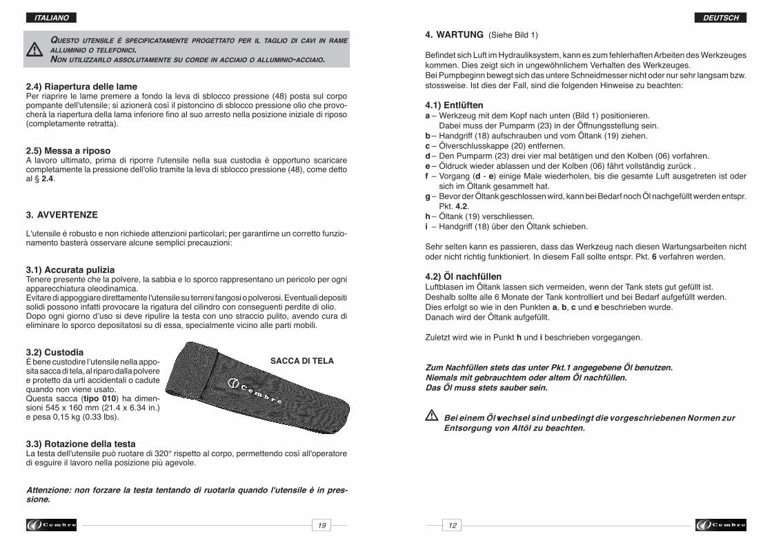
questo utensile è specificatamente progettato per il taglio Di cavi in rame alluminio o telefonici. non utilizzarlo assolutamente su corDe in acciaio o alluminio-acciaio.
2.4) Riapertura delle lamePer riaprire le lame premere a fondo la leva di sblocco pressione (48) posta sul corpo pompante dell'utensile; si azionerà così il pistoncino di sblocco pressione olio che provo-cherà la riapertura della lama inferiore fino al suo arresto nella posizione iniziale di riposo (completamente retratta).
2.5) Messa a riposoA lavoro ultimato, prima di riporre l'utensile nella sua custodia è opportuno scaricare completamente la pressione dell'olio tramite la leva di sblocco pressione (48), come detto al § 2.4.
3. AVVERTENZE
L'utensile é robusto e non richiede attenzioni particolari; per garantirne un corretto funzio-namento basterà osservare alcune semplici precauzioni:
3.1) Accurata puliziaTenere presente che la polvere, la sabbia e lo sporco rappresentano un pericolo per ogni apparecchiatura oleodinamica. Evitare di appoggiare direttamente l'utensile su terreni fangosi o polverosi. Eventuali depositi solidi possono infatti provocare la rigatura del cilindro con conseguenti perdite di olio. Dopo ogni giorno d’uso si deve ripulire la testa con uno straccio pulito, avendo cura di eliminare lo sporco depositatosi su di essa, specialmente vicino alle parti mobili.
3.2) CustodiaÈ bene custodire l’utensile nella appo-sita sacca di tela, al riparo dalla polvere e protetto da urti accidentali o cadute quando non viene usato.Questa sacca (tipo 010) ha dimen-sioni 545 x 160 mm (21.4 x 6.34 in.) e pesa 0,15 kg (0.33 lbs).
3.3) Rotazione della testaLa testa dell'utensile può ruotare di 320° rispetto al corpo, permettendo così all'operatore di esguire il lavoro nella posizione più agevole.
Attenzione: non forzare la testa tentando di ruotarla quando l'utensile è in pres-sione.
ITALIANO
SACCA DI TELA
DEUTSCH
13 18
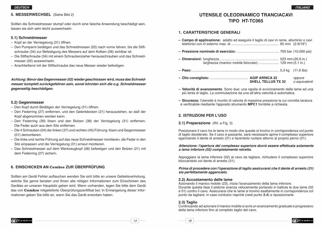
5. MESSERWECHSEL (Siehe Bild 2)
Sollten die Schneidmesser stumpf oder durch eine falsche Anwendung beschädigt sein, lassen sie sich sehr leicht auswechseln:
5.1) Schneidmesser– Kopf an der Verriegelung (31) öffnen.– Den Pumparm betätigen und das Schneidmesser (02) nach vorne fahren, bis die Stift- schraube (34) zur Befestigung des Messers auf dem Kolben (06) sichtbar ist. – Die Stiftschraube (34) mit einem Schraubenzieher herausschrauben und das Schneid- messer (02) auswechseln. – Anschließend mit der Stiftschraube das neue Messer wieder befestigen.
Achtung: Bevor das Gegenmesser (02) wieder geschlossen wird, muss das Schneid-messer komplett zurückgefahren sein, sonst könnten sich die o.g. Schneidmesser gegenseitig beschädigen.
5.2) Gegenmesser– Den Kopf durch Betätigen der Verriegelung (31) öffnen.– Den Federring (27) entfernen, und den Gelenkbolzen (21) herausziehen, so daß der Kopf abgenommen werden kann.– Den Federring (39) lösen und den Bolzen (38) der Verriegelung (31) entfernen. Die Feder auch aus dem Sitz entfernen.– Die 4 Schrauben (04) der linken (37) und rechten (45) Führung lösen und Gegenmesser (01) demontieren.– Die linke und rechte Führung auf das neue Schneidmesser montieren, die Feder in den Sitz einpassen und die Verriegelung (31) erneut montieren. – Das Schneidmesser auf dem Werkzeugkopf (08) befestigen und den Bolzen (21) mit dem Federring (27) sichern.
6. EINSCHICKEN AN Cembre ZUR ÜBERPRÜFUNG
Sollten am Gerät Fehler auftauchen wenden Sie sich bitte an unsere Gebietsvertretung, welche Sie gerne beraten und Ihnen alle nötigen Informationen zum Einschicken des Gerätes an unseren Hauptsitz geben wird. Wenn vorhanden, legen Sie bitte dem Gerät das von Cembre mitgelieferte Überprüfungszertifikat bei; In Ermangelung dieser Infor-mationen geben Sie bitte an, wann Sie das Gerät erworben haben.
UTENSILE OLEODINAMICO TRANCIACAVITIPO HT-TC065
1. CARATTERISTICHE GENERALI – Campo di applicazione: adatto ad eseguire il taglio di cavi in rame, alluminio o cavi telefonici con Ø esterno max. di ................................................. 65 mm (2-9/16")
– Pressione nominale di esercizio: ............................................ 700 bar (10,000 psi)
– Dimensioni: lunghezza ............................................................. 523 mm (20.6 in.) larghezza (manico mobile bloccato) ..................... 129 mm (5.1 in.)
– Peso: .......................................................................................... 5,3 kg (11.6 lbs) – Olio consigliato: ....................................... AGIP ARNICA 32 oppure SHELL TELLUS TX 32 o equivalenti
– Velocità di avanzamento. Sono due: una rapida di avvicinamento delle lame ed una più lenta di taglio. La commutazione da una all’altra velocità é automatica.
– Sicurezza: l'utensile è munito di valvola di massima pressione la cui corretta taratura è verificabile mediante l'apposito strumento MPC1 fornibile a richiesta.
2. ISTRUZIONI PER L’USO
2.1) Preparazione (Rif. a Fig. 3)
Posizionare il cavo tra le lame in modo che queste si trovino in corrispondenza col punto di taglio desiderato. Se il cavo è passante, sarà necessario aprire il complesso superiore sganciando il dente di arresto (31) e facendolo ruotare attorno al proprio perno (21).
Attenzione: l'apertura del complesso superiore dovrà essere effettuata solamente a lama inferiore (02) completamente retratta.
Appoggiare la lama inferiore (02) al cavo da tagliare, richiudere il complesso superiore bloccandolo col dente di arresto (31).
Prima di procedere con l'operazione di taglio assicurarsi che il dente di arresto (31) sia perfettamente agganciato.
2.2) Accostamento delle lameAzionando il manico mobile (23), inizia l'avanzamento della lama inferiore. Durante questa fase il pistone avanza velocemente portando in battuta le due lame (02 e 01) contro il cavo. Assicurarsi che le lame si trovino esattamente in corrispondenza col punto da tagliare; in caso contrario riaprirle (vedi punto 2.4) e riposizionarle.
2.3) TaglioContinuando ad azionare il manico mobile si avrà un avanzamento graduale e progressivo della lama inferiore fino al completo taglio del cavo.
ITALIANO
ESPAÑOL
HERRAMIENTA HIDRAULICA DE CORTETIPO HT-TC065
1. CARACTERISTICAS GENERALES
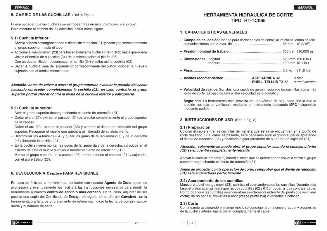
– Campo de aplicación: idóneo para cortar cables de cobre, aluminio así como de tele- comunicaciones con ø max. de .................................................. 65 mm (2-9/16")
– Presión nominal de trabajo: .................................................... 700 bar (10,000 psi)
– Dimensiones: longitud .............................................................. 523 mm (20.6 in.) anchura .............................................................. 129 mm (5.1 in.)
– Peso: .......................................................................................... 5,3 kg (11.6 lbs)
– Aceites recomendados: ........................... AGIP ARNICA 32 o bien SHELL TELLUS TX 32 o equivalentes
– Velocidad de avance. Son dos: una rápida de aproximación de las cuchillas y otra más lenta de corte. El paso de una a otra velocidad es automático.
– Seguridad. La herramienta esta provista de una válvula de seguridad con la que la presión correcta es verificable mediante el instrumento adecuado MPC1 disponible mediante pedido.
2. INSTRUCCIONES DE USO (Ref. a Fig. 3)
2.1) PreparaciónColocar el cable entre las cuchillas de manera que éstas se encuentren en el punto de corte deseado. Si el cable es pasante, será necesario abrir el grupo superior apretando el diente de retención (31) y haciéndola girar alrededor de su perno de sujeción (21).
Atención: solamente se puede abrir el grupo superior cuando la cuchilla inferior (02) se encuentre completamente retraída.
Apoyar la cuchilla inferior (02) contra el cable que se quiere cortar, volver a cerrar el grupo superior enganchando el diente de retención (31).
Antes de proceder con la operación de corte, comprobar que el diente de retención (31) esté enganchado perfectamente.
2.2) Acercamiento de las cuchillasManiobrando el mango móvil (23), se inicia el acercamiento de las cuchillas. Durante esta fase, el pistón avanza hasta que las dos cuchillas (02 y 01) choquen a tope contra el cable. Comprobar que las cuchillas se encuentran exactamente enfrente del punto que se quiere cortar; de no ser así, volverlas a abrir (véase punto 2.4) y volverlas a colocar.
2.3) CorteContinuando accionando el mango móvil, se conseguirá un avance gradual y progresivo de la cuchilla inferior hasta cortar completamente el cable.
17 14
ESPAÑOL
5. CAMBIO DE LAS CUCHILLAS (Ref. a Fig. 2)
Puede suceder que las cuchillas se estropeen tras un uso prolongado o impropio.Para efectuar el cambio de las cuchillas, actúe como sigue:
5.1) Cuchilla inferior:– Abrir la cabeza desenganchando el diente de retención (31) y hacer girar completamente el grupo superior, hasta el tope. – Accionar el mango móvil (23) para hacer avanzar la cuchilla inferior (02) hasta que quede visible el tornillo de sujección (34) de la misma sobre el pistón (06).– Con un destornillador, desenroscar el tornillo (34) y soltar así la cuchilla (02). – Sacar la cuchilla vieja del alojamiento correspondiente del pistón, colocar la nueva y sujetarla con el tornillo mencionado.
Atención: antes de volver a cerrar el grupo superior, evacuar la presión del aceite haciendo retroceder completamente la cuchilla (02); en caso contrario, el grupo superior podría chocar contra la arista de la cuchilla inferior y estropearla.
5.2) Cuchilla superior:– Abrir el grupo superior desenganchando el diente de retención (31). – Quitar el aro (27), extraer el pasador (21) para soltar completamente el grupo superior de la cabeza. – Quitar el aro (39), extraer el pasador (38) y separar el diente de retención del grupo superior. Recuperar el muelle que quedará así liberado de su alojamiento.– Destornillar los 4 tornillos (04) y quitar las guías de la izquierda (37) y de la derecha (45) liberando la cuchilla (01).– En la cuchilla nueva montar las guías de la izquierda y de la derecha, introducir en el asiento de ésta el muelle y volver a montar el diente de retención (31).– Montar el grupo superior en la cabeza (08), meter a fondo el pasador (21) y sujetarlo con el aro elástico (27).
6. DEVOLUCION A Cembre PARA REVISIONES
En caso de fallo de la herramienta, contactar con nuestro Agente de Zona quien les aconsejará y eventualmente les facilitará las instrucciones necesarias para remitir la herramienta a nuestro centro de servicio mas cercano. En tal caso, adjuntar de ser posible una copia del Certificado de Ensayo entregado en su día por Cembre con la herramienta o a falta de otro elemento de referencia indicar la fecha de compra aproxi-mada y el número de serie.
15 16
ESPAÑOL
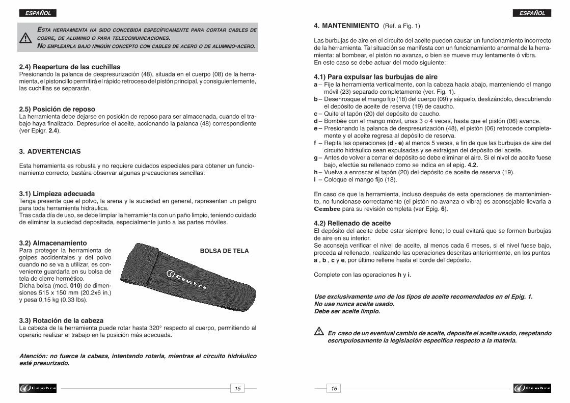
BOLSA DE TELA
esta herramienta ha siDo concebiDa específicamente para cortar cables De cobre, De aluminio o para telecomunicaciones. no emplearla bajo ningún concepto con cables De acero o De aluminio-acero.
2.4) Reapertura de las cuchillasPresionando la palanca de despresurización (48), situada en el cuerpo (08) de la herra-mienta, el pistoncillo permitirá el rápido retroceso del pistón principal, y consiguientemente, las cuchillas se separarán.
2.5) Posición de reposoLa herramienta debe dejarse en posición de reposo para ser almacenada, cuando el tra-bajo haya finalizado. Depresurice el aceite, accionando la palanca (48) correspondiente (ver Epigr. 2.4).
3. ADVERTENCIAS
Esta herramienta es robusta y no requiere cuidados especiales para obtener un funcio-namiento correcto, bastára observar algunas precauciones sencillas:
3.1) Limpieza adecuadaTenga presente que el polvo, la arena y la suciedad en general, rapresentan un peligropara toda herramienta hidráulica. Tras cada día de uso, se debe limpiar la herramienta con un paño limpio, teniendo cuidado de eliminar la suciedad depositada, especialmente junto a las partes móviles.
3.2) AlmacenamientoPara proteger la herramienta de golpes accidentales y del polvo cuando no se va a utilizar, es con-veniente guardarla en su bolsa de tela de cierre hermético. Dicha bolsa (mod. 010) de dimen-siones 515 x 150 mm (20.2x6 in.) y pesa 0,15 kg (0.33 lbs).
3.3) Rotación de la cabezaLa cabeza de la herramienta puede rotar hasta 320° respecto al cuerpo, permitiendo al operario realizar el trabajo en la posición más adecuada.
Atención: no fuerce la cabeza, intentando rotarla, mientras el circuito hidráulico esté presurizado.
ESPAÑOL
4. MANTENIMIENTO (Ref. a Fig. 1)
Las burbujas de aire en el circuito del aceite pueden causar un funcionamiento incorrecto de la herramienta. Tal situación se manifesta con un funcionamiento anormal de la herra-mienta: al bombear, el pistón no avanza, o bien se mueve muy lentamente ó vibra.En este caso se debe actuar del modo siguiente:
4.1) Para expulsar las burbujas de airea – Fije la herramienta verticalmente, con la cabeza hacia abajo, manteniendo el mango móvil (23) separado completamente (ver. Fig. 1).b – Desenrosque el mango fijo (18) del cuerpo (09) y sáquelo, deslizándolo, descubriendo el depósito de aceite de reserva (19) de caucho.c – Quite el tapón (20) del depósito de caucho.d – Bombée con el mango móvil, unas 3 o 4 veces, hasta que el pistón (06) avance.e – Presionando la palanca de despresurización (48), el pistón (06) retrocede completa- mente y el aceite regresa al depósito de reserva.f – Repita las operaciones (d - e) al menos 5 veces, a fin de que las burbujas de aire del circuito hidráulico sean expulsadas y se extraigan del depósito del aceite. g – Antes de volver a cerrar el depósito se debe eliminar el aire. Si el nivel de aceite fuese bajo, efectúe su rellenado como se indica en el epig. 4.2.h – Vuelva a enroscar el tapón (20) del depósito de aceite de reserva (19).i – Coloque el mango fijo (18). En caso de que la herramienta, incluso después de esta operaciones de mantenimien-to, no funcionase correctamente (el pistón no avanza o vibra) es aconsejable llevarla a Cembre para su revisión completa (ver Epig. 6).
4.2) Rellenado de aceiteEl depósito del aceite debe estar siempre lleno; lo cual evitará que se formen burbujas de aire en su interior.Se aconseja verificar el nivel de aceite, al menos cada 6 meses, si el nivel fuese bajo, proceda al rellenado, realizando las operaciones descritas anteriormente, en los puntosa , b , c y e, por último rellene hasta el borde del depósito.
Complete con las operaciones h y i.
Use exclusivamente uno de los tipos de aceite recomendados en el Epig. 1.No use nunca aceite usado. Debe ser aceite limpio.
En caso de un eventual cambio de aceite, deposite el aceite usado, respetando escrupulosamente la legislación especifica respecto a la materia.