Embed Size (px)
Citation preview
Enhancing Realism of Mixed Reality Applications through Real-TimeDepth-Imaging Devices in X3D
Tobias Franke∗ Svenja Kahn† Manuel Olbrich‡ Yvonne Jung§
Fraunhofer Institut fur Graphische DatenverarbeitungDarmstadt, Germany
Abstract
Until recently, depth sensing cameras have been used almost exclu-sively in research due to the high costs of such specialized equip-ment. With the introduction of the Microsoft Kinect device, real-time depth imaging is now available for the ordinary developer atlow expenses and so far it has been received with great interest fromboth the research and hobby developer community. The underlyingOpenNI framework not only allows to extract the depth image fromthe camera, but also provides tracking information of gestures oruser skeletons. In this paper, we present a framework to includedepth sensing devices into X3D in order to enhance visual fidelityof X3D Mixed Reality applications by introducing some extensionsfor advanced rendering techniques. We furthermore outline how tocalibrate depth and image data in a meaningful way through cali-bration for devices that do not already come with precalibrated sen-sors, as well as a discussion of some of the OpenNI functionalitythat X3D can benefit from in the future.
CR Categories: I.3.7 [Three-Dimensional Graphics and Real-ism]: Color, shading, shadowing, and texture I.3.6 [Methodologyand Techniques]: Standards—Languages
Keywords: X3D, Augmented Reality, Mixed Reality, Rendering
1 Introduction
With the introduction of Microsoft’s Kinect depth imaging deviceand the subsequent release of the OpenNI framework together withthe PrimeSense NITE SDK [OpenNI 2011] to enable user trackingand gesture recognition, the Mixed Reality (MR) and electronic artperformance scene saw a sudden increase in installations and demosusing these devices. Blog pages such as “kinecthacks.net” display awide range of hobbyist applications ranging from gesture-enabledcontrollers for already existing games to playful art experimenta-tion or even robots. Most of these applications make use of toolkitssuch as openFrameworks or Cider to create graphical output andrequire considerable programming skills to create even the simplestapplications. We believe this kind of application development tobe inside the domain of X3D [Web3DConsortium 2008b]. Cheapdepth sensing cameras are now available from different vendors andwith the underlying support of the OpenNI standard they are ableto provide tracking data for Natural Interaction (NI). However, even
∗email:[email protected]†email:[email protected]‡email:[email protected]§email:[email protected]
without NI sensing data, the depth image alone is the basis for sev-eral effects in any MR application.
In this paper we discuss several enhancements for X3D to enablethe use of all OpenNI compatible devices and general depth cam-eras in section 3. We provide an overview of a generic subsys-tem that supports MR interaction with X3D and how non-calibrateddepth cameras can be configured to match up their data with a givenbackground image in section 4. In the following section 5, we an-alyze several effects for MR applications, which can be achievedwith a depth image of the real scene. Ultimately, MR applicationwriters will benefit from the X3D standard and faster development.
2 Related Work
Previous approaches used Time-of-Flight (ToF) cameras for real-time depth imaging [Oggier et al. 2006]. ToF cameras emit near-infrared modulated light which is reflected by the scene. The phaseshift of the reflected light is used to calculate the distance to themeasured objects. An overview on ToF sensors and applicationswhich use real-time depth imaging is given in [Kolb et al. 2009].
[Schiller et al. 2010] provide a starting framework for incorporatinga ToF camera into a Mixed Reality system. The captured depth mapof the scene is used to create a background model of the scene withthe background image being used as a texture. The reconstructedscene is used for shadow mapping, and light sources are inferredfrom the background image or placed manually. Viewed from thecamera’s original angle, shadows are inserted into the image withthe correct topological distortion. Occluding real geometry is han-dled by comparing depth values from the camera’s image with therendered objects.
[Kahn et al. 2010] propose an Augmented Reality system whichuses real-time depth imaging for 3D discrepancy checks. They cou-ple a ToF camera and a color camera on a rigid camera rig and usecamera tracking algorithms to estimate the positions of both cam-eras while the user moves the rig around an object. The depth im-ages of the ToF camera are used to compare the surface of the realobject with a 3D model of the object. The Augmented Reality (AR)visualization of the differences assists the user in detecting differ-ences between the real object and the 3D model, which for instanceis helpful for maintenance tasks.
Visualization techniques for advanced AR/MR rendering especiallyin the context of X3D were presented in [Jung et al. 2007] and [Lee2009]. Both proposals presented nodes for integrating live cam-era streams into X3D. Both papers also discussed MR visualizationproblems like occlusions (which in [Lee 2009] were only tackledon a rather primitive level by extending the Shape node with anisGhost flag) and MR relighting. In [Jung et al. 2007] the latteris solved with a combination of image-based rendering and differ-ential rendering by also introducing some shadowing extensions,whereas in [Lee 2009] this topic is left open for future work.
Shadow mapping, due to its requirement of obtaining the depthvalues from the camera and light perspective, integrates well withdepth images for real scenes. In the remainder of this section we
will review previous approaches of integrating shadowing tech-niques into X3D. For an introduction and comprehensive overviewon real-time shadows in general we refer to [Akenine-Moller et al.2008, p. 331 ff.]. The X3D lighting model [Web3DConsortium2008b] still does not include any form of real-time shadows. How-ever, there have already been some proposals to include real-timeshadows into X3D. For instance in [Sudarsky 2001] shadows fordynamic scenes are generated, but only on user defined surfacesand for point lights that must be outside of the current scene. TheShadow node extension from Octaga [Octaga 2009] supports allX3D light types and provides a detail field parameter that is usedto specify the resolution of the shadows. However, soft shadows arenot supported, and the implementation as Group node, which linksall occluders and lights, does not look very natural.
BS Contact [Bitmanagement 2002] provides shaders, which canbe used to generate shadows, but the developer has to handle theshadow map generation and processing per object directly in theshader code. This may be a very flexible solution but not onewhich all scene authors can handle and would intuitively think of.Kamburelis presented another set of node extensions for integratingshadow maps and projective texture mapping into X3D [Kambu-relis 2010]. However, the proposed extensions only deal with sim-ple standard shadow mapping and, on a rather primitive level, PCFshadows [Reeves et al. 1987]. Furthermore, the proposed shaderintegration is very low-level and some of the proposed extensionseven seem to be mutual contradictory. Nevertheless, despite theirdrawbacks some of the proposed extensions might ease improvingrendering quality a lot and should be simple to use, since e.g. thenew GeneratedShadowMap node in combination with the Texture-CoordinateGenerator extension for calculating projective texturecoordinates is rather close to the X3D design principles.
3 DepthSensor and accompanying Nodes
In [Behr et al. 2004], an interface specification for external de-vices interacting with X3D was proposed. These node types aredescendants of the X3DDirectSensorNode [Behr et al. 2005]and specify the data to be received, not the device itself. In linewith this previous discussion, we present a DepthSensor to re-ceive depth images from any camera type the underlying system isable to provide, and an NISensor for OpenNI-supported devices.
The DepthSensor, whose interface is shown next, provides abasic SFImage of a ToF camera or similar device. On many devices,this depth data is represented with either 16 bit unsigned or floatvalues, implying equivalent data type support in X3D images todirectly use the same information on the GPU.
DepthSensor : X3DDirectSensorNode SFImage [out] depthImageSFInt32 [in,out] width 640SFInt32 [in,out] height 480SFInt32 [in,out] fps 30SFBool [in,out] normalizeDepth TRUESFString [] label ""
On top of it, the NISensor provides basic fields that can be ac-cessed through OpenNI production nodes.
NISensor : DepthSensor ...SFImage [out] colorImageSFBool [in,out] alignViewports TRUEMFInt32 [out] users
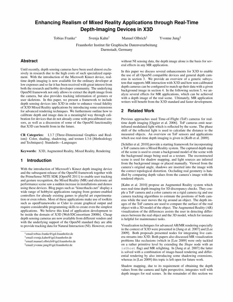
Figure 1: A skeleton is tracked from the depth image of a Kinectdevice inside InstantReality [IR 2010].
Several fields are used to configure the node upon instantiation:width, height and fps are parameters of the SFImage out-slots returned from the NISensor node (i.e. colorImage anddepthImage). The field alignViewports is a boolean valueto automatically transform either the colorImage or the depthImageinto the viewing space of each other to compensate for the parallaxdistortion if both cameras are set apart. OpenNI provides such func-tionality, but manual calibration may be beneficial for other devices.normalizeDepth is used to transform depth values into scaledfloating point values from [0.0, 1.0] instead of the raw range anddata type provided by the device. For user tracking, a field userscan provide a list of ID’s assigned to each person tracked by the de-vice. To track several users inside a scene, a special UserSensornode provides the data for each individual ID.
UserSensor : X3DDirectSensorNode ...SFInt32 [in,out] userID 0SFImage [out] userMaskMFVec3f [out] jointPositionsMFRotation [out] jointOrientationsSFString [out] gesture
The node is identified through its userID, which is assigned to atracked person. If no such person exists, the userID can be reset toa standard value. A binary image userMask is provided to iden-tify the pixels that have been assigned to the same user ID, whichcan be used for stencil operations. The eventOut slot gestureprovides a basic string of a recognized gesture or pose from theuser. Detailed information about the gesture is not handled insideOpenNI. Instead, OpenNI refers to proprietary middleware, whichat this moment is not yet standardized. However, a discussion forspecific gesture sensors could be relevant for future work.
Skeleton tracking is achieved with the help of two eventOut fields:jointPositions and jointOrientations, as can be seenin figure 1. These values can be used for character animation,though in our tests we noticed that the jointOrientationsprovided by OpenNI are too unstable for this purpose. Anotherproblem is the simplification of the reconstructed skeleton, whichhas far less joints than a common rigged character. To animatecomplex H-Anim characters [Web3DConsortium 2008a], we usedCCD1 to calculate joint orientations based on the recognized jointpositions. This approach allows stable animations based on theskeleton information also for skinned H-Anim figures.
1Cyclic Coordinate Descent – an inverse kinematics approach that solvesthe IK problem through optimization [Canutescu and Dunbrack 2003].
(a)
(b) (c) (d) (e)
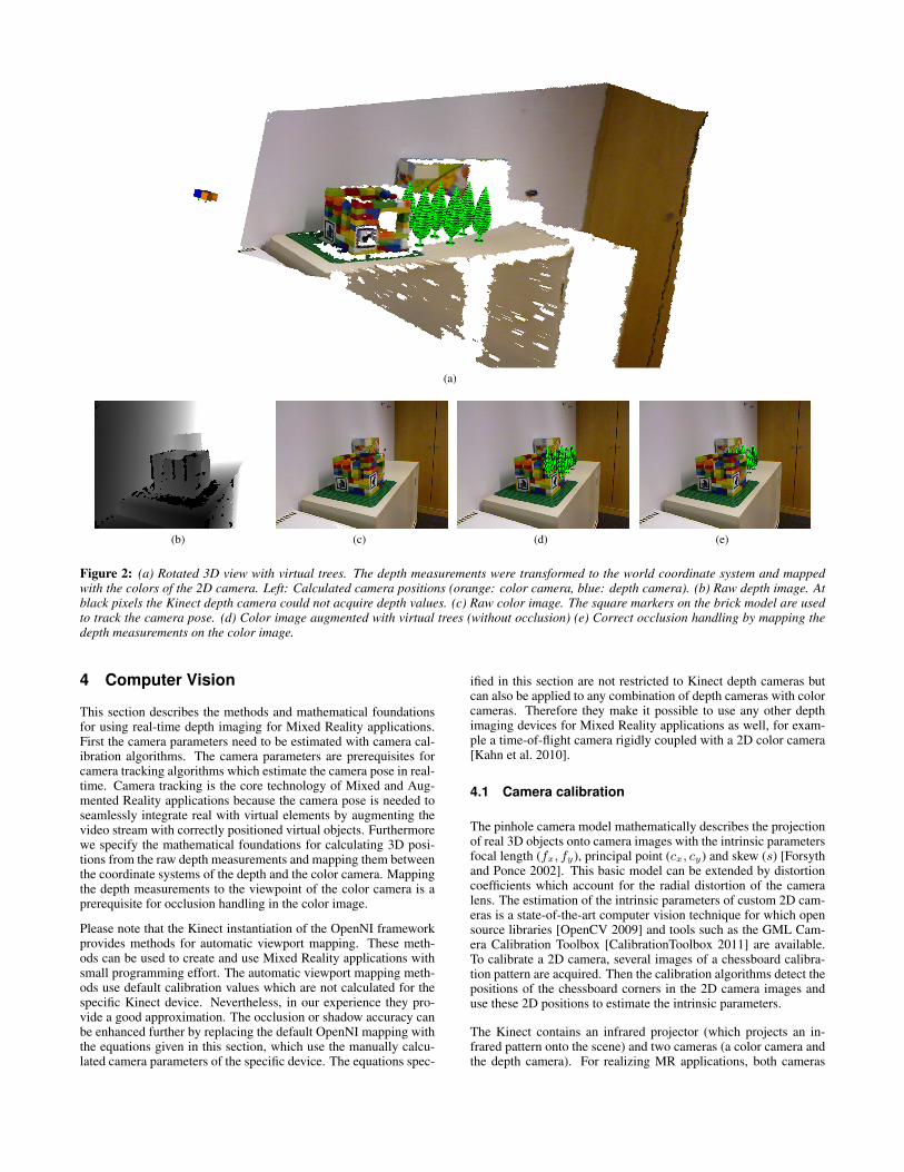
Figure 2: (a) Rotated 3D view with virtual trees. The depth measurements were transformed to the world coordinate system and mappedwith the colors of the 2D camera. Left: Calculated camera positions (orange: color camera, blue: depth camera). (b) Raw depth image. Atblack pixels the Kinect depth camera could not acquire depth values. (c) Raw color image. The square markers on the brick model are usedto track the camera pose. (d) Color image augmented with virtual trees (without occlusion) (e) Correct occlusion handling by mapping thedepth measurements on the color image.
4 Computer Vision
This section describes the methods and mathematical foundationsfor using real-time depth imaging for Mixed Reality applications.First the camera parameters need to be estimated with camera cal-ibration algorithms. The camera parameters are prerequisites forcamera tracking algorithms which estimate the camera pose in real-time. Camera tracking is the core technology of Mixed and Aug-mented Reality applications because the camera pose is needed toseamlessly integrate real with virtual elements by augmenting thevideo stream with correctly positioned virtual objects. Furthermorewe specify the mathematical foundations for calculating 3D posi-tions from the raw depth measurements and mapping them betweenthe coordinate systems of the depth and the color camera. Mappingthe depth measurements to the viewpoint of the color camera is aprerequisite for occlusion handling in the color image.
Please note that the Kinect instantiation of the OpenNI frameworkprovides methods for automatic viewport mapping. These meth-ods can be used to create and use Mixed Reality applications withsmall programming effort. The automatic viewport mapping meth-ods use default calibration values which are not calculated for thespecific Kinect device. Nevertheless, in our experience they pro-vide a good approximation. The occlusion or shadow accuracy canbe enhanced further by replacing the default OpenNI mapping withthe equations given in this section, which use the manually calcu-lated camera parameters of the specific device. The equations spec-
ified in this section are not restricted to Kinect depth cameras butcan also be applied to any combination of depth cameras with colorcameras. Therefore they make it possible to use any other depthimaging devices for Mixed Reality applications as well, for exam-ple a time-of-flight camera rigidly coupled with a 2D color camera[Kahn et al. 2010].
4.1 Camera calibration
The pinhole camera model mathematically describes the projectionof real 3D objects onto camera images with the intrinsic parametersfocal length (fx, fy), principal point (cx, cy) and skew (s) [Forsythand Ponce 2002]. This basic model can be extended by distortioncoefficients which account for the radial distortion of the cameralens. The estimation of the intrinsic parameters of custom 2D cam-eras is a state-of-the-art computer vision technique for which opensource libraries [OpenCV 2009] and tools such as the GML Cam-era Calibration Toolbox [CalibrationToolbox 2011] are available.To calibrate a 2D camera, several images of a chessboard calibra-tion pattern are acquired. Then the calibration algorithms detect thepositions of the chessboard corners in the 2D camera images anduse these 2D positions to estimate the intrinsic parameters.
The Kinect contains an infrared projector (which projects an in-frared pattern onto the scene) and two cameras (a color camera andthe depth camera). For realizing MR applications, both cameras
need to be calibrated intrinsically. The default calibration proce-dure can be used for the color camera. However, the checkerboardpattern is not visible in the depth image. Therefore we make useof the fact that the depth camera is an infrared camera (which de-tects the infrared pattern of the projector to calculate depth valuesfor each pixel). Instead of acquiring the depth image, the raw in-frared image of the depth camera is acquired with the OpenNI inter-face. By covering the infrared projector with opaque tape to removethe infrared pattern from the image and illuminating the chessboardpattern with an external infrared lamp, the chessboard becomes vis-ible in the infrared images of the depth camera. Then the customintrinsic calibration procedures for 2D cameras can also be appliedon the infrared images of the depth camera.
Due to the fact that the Kinect device contains not only a depthcamera but also a color camera it is very well suited for realizingMixed Reality applications: Whereas the depth data provides thebasis for real-time occlusion calculation and shadow mapping, theposition of both cameras can be calculated by tracking the posi-tion of the 2D camera with camera tracking algorithms and theninferring the position of the depth camera from the relative trans-formation (∆R,∆t) between the two cameras. As well as the in-trinsic parameters, the relative transformation between the camerasonly needs to be calculated once in an offline calibration step. TheKinectAutoCalibration tool written by Engelhard [Engelhard 2010]makes use of the OpenCV library [OpenCV 2009] to calculate therelative transformation between the depth and the color camera.
4.2 Camera tracking
For a seamless integration of virtual objects into camera imagesthe pose (position and orientation) of the camera needs to be know.The position and rotation of the camera are calculated with cameratracking algorithms. The most commonly used method for cam-era pose estimation is marker tracking. These fiducial markers areattached to the scene and have a contour which is easy to detectwith image processing algorithms. Image 2(c) shows two squaremarkers which are attached to the brick model. The coordinates ofthe markers are specified in the world coordinate system and themarkers are tracked with the computer vision framework InstantVi-sion [Becker et al. 2007]. Other publicly available tools such asARToolKit [ART 2008] also contain easy to use marker trackingalgorithms.
Marker based camera tracking has the drawback that the camerapose can only be calculated if markers are visible in the currentcamera image. Therefore we combine markerless camera trackingwith structure from motion 3D reconstruction [Bleser et al. 2006].While the camera is moved, this approach detects characteristic im-age features with a Shi-Tomasi corner detector [Shi and Tomasi1994] and tracks these 2D image features with a Lucas Kanadetracker [Wuest 2008]. Then the 3D positions of the tracked fea-tures are reconstructed online via triangulation [Bleser et al. 2006].Finally the 2D-3D correspondences between the 2D image coordi-nates of the tracked features and their reconstructed 3D coordinatesare used to calculate the camera pose if no marker is visible.
When a color camera is combined with a depth camera to createmore realistic MR applications (e.g. when the Kinect is used forreal-time depth imaging), not only the pose of the color cameraneeds to be known but also the pose of the depth camera. The poseof the depth camera can not be calculated directly from the depthimage because image features like markers are not visible in thedepth image (see figure 2(b)). Therefore the pose of the depth cam-era is calculated from the tracked 2D image of the color camerawith equation 1. (∆R,∆t) is the relative transformation betweenthe two cameras which was calculated in the offline calibration step.
RD = RC · ∆R
tD = RC · tC + ∆t(1)
4.3 Conversion from depth values to 3D points
To calculate occlusions or shadow mapping for augmentations inthe color image, the depth measurements of the depth camera needto be mapped onto the color image. Therefore the raw depth valuesare first transformed to 3D points and then projected onto the 2Dimage of the color camera. Equation 2 transforms the 1D depthvalue dcam of a pixel (px, py) in the 2D image coordinate systemof the depth camera to a 3D point pCCS(D) in the depth cameracoordinate system CCS(D).
pCCS(D) =
(px − cx) · 1fx
· dcam(py − cy) · 1
fy· dcam
dcam
(2)
The origin of the camera coordinate systems is the camera center.Thus points in the camera coordinate system are specified relativeto the camera position and orientation which changes whenever thecamera is moved. To obtain the 3D world coordinates of 3D points(which are independent of the camera pose), the 3D points are trans-formed to the world coordinate system with equation 3.
pWCS = (RD)−1 · (pCCS(D) − tD) (3)
Finally equation 4 is used to project 3D points from the world co-ordinate system to 2D coordinates pICS(C) in the camera image ofthe color camera. Here KC is the camera calibration matrix of thecolor camera which contains the intrinsic parameters that were cal-culated with the intrinsic calibration procedure described in section4.1. ICS(C) is the 2D image coordinate system of the color camera.
pICS(C) = KC((RC · pWCS) + tC) (4)
Figure 2(b) and 2(c) show the depth and the color image acquired bya Kinect camera. The raw depth measurements were transformedto the world coordinate system and finally mapped onto the colorimage. The 3D points in the world coordinate system and theircolor mapping as well as the calculated poses of both cameras arevisualized in figure 2(a). Furthermore, occlusion was calculatedwith the depth values mapped onto the color image (which will bedescribed in more detail in section 5.1).
4.4 InstantIO
Interfacing between input/output devices in general (and specifi-cally the computer vision component) and the X3D-based scene-graph is not done directly, but through a layer called InstantIO [Behret al. 2005], which provides a general sensor abstraction for IO de-vices. In a similar fashion to X3D, the layer provides a rich setof nodes with slots that either send or receive data to other nodesvia a routing mechanism. Device nodes (or backends respectively)in InstantIO generally do not refer to a specific piece of hardware,but rather to a group of similar devices. For instance, a video nodecan provide input from a webcam, a TV device or any other videostream the underlying system detects.
We connect InstantIO, which is an integral part of the Instant Real-ity framework [IR 2010], to the X3D-based rendering system eitherwith a specialized X3DDirectSensor node or alternatively for
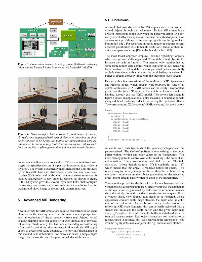
Figure 3: Connection between tracking system (left) and rendering(right) in the Instant Reality framework via InstantIO (middle).
Figure 4: From top left to bottom right: (a) real image of a room;(b) real scene augmented with virtual character (note that the char-acter appears to be before the table); (c) augmentation with ad-ditional occlusion handling (note that the character still seems tofloat on the floor); (d) augmentation with occlusion and shadows.
convenience with a sensor node called IOSensor initialized witha type that specifies the sort of input that is expected (e.g. video orjoystick). The system dynamically maps fields to the slots providedby the InstantIO hardware abstraction, which can then be reroutedto other X3D nodes and fields. Our computer vision subsystem ishandled analogously to any other IO device: as shown in figure3, the IO system provides several (dynamic) fields that configurethe tracking mechanism and allow grabbing the results such as thebackground video image or the intrinsic camera matrices.
5 Advanced MR Rendering
Several effects for MR simulations require reconstruction of sceneelements or the viewing area from the main camera perspective,such as occlusion of virtual geometry from real objects, virtualshadow mapping onto real geometry or even simulation of physicalinteraction. Traditionally, this has been achieved by reconstructinga 3D model a priori and then tracking it alongside the MR appli-cation to access real scene geometry. The obvious disadvantage ofthis method is its inflexibility. For many use cases, a simple depthimage can remove the need for prior knowledge of the scene.
5.1 Occlusions
A simple but powerful effect for MR applications is occlusion ofvirtual objects through the real scene. Typical MR scenes leavea weird impression on the user when the perceived depth isn’t cor-rectly reflected by the application, because the virtual object alwaysappears on top of things (compare top right image in figure 4 vs.bottom left one). For rasterization-based rendering engines severaldifferent possibilities exist to handle occlusions, but all of them re-quire multipass rendering [Diefenbach and Badler 1997].
The most trivial approach employs invisible “ghosting” objects,which are geometrically registered 3D models of real objects, forinstance the table in figure 4. This method only requires havingsome basic render state control, which explicitly allows renderingthe reconstructed 3D models of real objects first (which potentiallyocclude virtual ones) – but only into the depth buffer, since the colorbuffer is already correctly filled with the incoming video stream.
Hence, with a few extensions of the traditional X3D Appearanceand Material nodes, which already were proposed in [Jung et al.2007], occlusions in AR/MR scenes can be easily incorporated,given that the (real) 3D objects, for which occlusions should behandled, already exist as (X)3D model. The bottom left image infigure 4 shows an application of color masking in combination withusing a defined rendering order for achieving the occlusion effects.The corresponding X3D code (in VRML encoding) is shown below.
Shape appearance Appearance sortKey -1colorMaskMode ColorMaskMode maskR FALSEmaskG FALSEmaskB FALSEmaskA FALSE
geometry IndexedFaceSet ...
As can be seen, only two fields of the geometry’s Appearance areparameterized. The ColorMaskMode allows writing to the depthbuffer without writing any color values to the framebuffer. Thisnode thereby permits control over color masking – the color chan-nel is written if the corresponding mask field is true. The fieldsortKey (whose default value is “0”) is explicitly set to “-1”,which means that this object is rendered before all others. Thisis necessary to initially stamp out the depth buffer without settingthe color – otherwise another object (depending on the renderingorder) might already have written its color to the framebuffer.
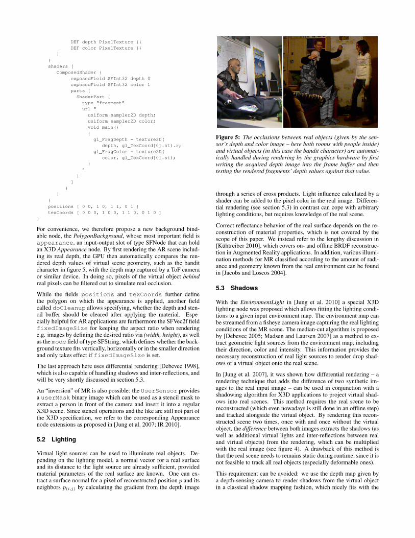
The second approach for dealing with occlusions between real andvirtual objects, as shown in figure 5, directly employs the depth mapof the real scene as generated by ToF cameras or similar devices,since this nicely fits with standard rasterization techniques. First,a window-sized, view-aligned quad needs to be rendered, whoseappearance contains both image streams, the depth and the colormap of the real scene. As can be seen in the shader part of thefollowing X3D code fragment, this can be easily achieved with ashader that initializes the depth buffer with the given depth mapvia gl_FragDepth, while the color buffer is initialized with thestandard camera image. Real objects hence are not required to bereconstructed in advance, but – as is shown in the screenshots – caneven be highly deformable objects like e.g. humans with clothes.
PolygonBackground appearance Appearance
texture MultiTexture texture [
DEF depth PixelTexture DEF color PixelTexture
]shaders [
ComposedShader exposedField SFInt32 depth 0exposedField SFInt32 color 1parts [ShaderPart
type "fragment"url "
uniform sampler2D depth;uniform sampler2D color;void main()gl_FragDepth = texture2D(
depth, gl_TexCoord[0].st).r;gl_FragColor = texture2D(
color, gl_TexCoord[0].st);
"
]
]positions [ 0 0, 1 0, 1 1, 0 1 ]texCoords [ 0 0 0, 1 0 0, 1 1 0, 0 1 0 ]
For convenience, we therefore propose a new background bind-able node, the PolygonBackground, whose most important field isappearance, an input-output slot of type SFNode that can holdan X3D Appearance node. By first rendering the AR scene includ-ing its real depth, the GPU then automatically compares the ren-dered depth values of virtual scene geometry, such as the banditcharacter in figure 5, with the depth map captured by a ToF cameraor similar device. In doing so, pixels of the virtual object behindreal pixels can be filtered out to simulate real occlusion.
While the fields positions and texCoords further definethe polygon on which the appearance is applied, another fieldcalled doCleanup allows specifying, whether the depth and sten-cil buffer should be cleared after applying the material. Espe-cially helpful for AR applications are furthermore the SFVec2f fieldfixedImageSize for keeping the aspect ratio when renderinge.g. images by defining the desired ratio via (width, height), as wellas the mode field of type SFString, which defines whether the back-ground texture fits vertically, horizontally or in the smaller directionand only takes effect if fixedImageSize is set.
The last approach here uses differential rendering [Debevec 1998],which is also capable of handling shadows and inter-reflections, andwill be very shortly discussed in section 5.3.
An “inversion” of MR is also possible: the UserSensor providesa userMask binary image which can be used as a stencil mask toextract a person in front of the camera and insert it into a regularX3D scene. Since stencil operations and the like are still not part ofthe X3D specification, we refer to the corresponding Appearancenode extensions as proposed in [Jung et al. 2007; IR 2010].
5.2 Lighting
Virtual light sources can be used to illuminate real objects. De-pending on the lighting model, a normal vector for a real surfaceand its distance to the light source are already sufficient, providedmaterial parameters of the real surface are known. One can ex-tract a surface normal for a pixel of reconstructed position p and itsneighbors p(i,j) by calculating the gradient from the depth image
Figure 5: The occlusions between real objects (given by the sen-sor’s depth and color image – here both rooms with people inside)and virtual objects (in this case the bandit character) are automat-ically handled during rendering by the graphics hardware by firstwriting the acquired depth image into the frame buffer and thentesting the rendered fragments’ depth values against that value.
through a series of cross products. Light influence calculated by ashader can be added to the pixel color in the real image. Differen-tial rendering (see section 5.3) in contrast can cope with arbitrarylighting conditions, but requires knowledge of the real scene.
Correct reflectance behavior of the real surface depends on the re-construction of material properties, which is not covered by thescope of this paper. We instead refer to the lengthy discussion in[Kuhtreiber 2010], which covers on- and offline BRDF reconstruc-tion in Augmented Reality applications. In addition, various illumi-nation methods for MR classified according to the amount of radi-ance and geometry known from the real environment can be foundin [Jacobs and Loscos 2004].
5.3 Shadows
With the EnvironmentLight in [Jung et al. 2010] a special X3Dlighting node was proposed which allows fitting the lighting condi-tions to a given input environment map. The environment map canbe streamed from a fisheye camera image capturing the real lightingconditions of the MR scene. The median-cut algorithm is proposedby [Debevec 2005; Madsen and Laursen 2007] as a method to ex-tract geometric light sources from the environment map, includingtheir direction, color and intensity. This information provides thenecessary reconstruction of real light sources to render drop shad-ows of a virtual object onto the real scene.
In [Jung et al. 2007], it was shown how differential rendering – arendering technique that adds the difference of two synthetic im-ages to the real input image – can be used in conjunction with ashadowing algorithm for X3D applications to project virtual shad-ows into real scenes. This method requires the real scene to bereconstructed (which even nowadays is still done in an offline step)and tracked alongside the virtual object. By rendering this recon-structed scene two times, once with and once without the virtualobject, the difference between both images extracts the shadows (aswell as additional virtual lights and inter-reflections between realand virtual objects) from the rendering, which can be multipliedwith the real image (see figure 4). A drawback of this method isthat the real scene needs to remains static during runtime, since it isnot feasible to track all real objects (especially deformable ones).
This requirement can be avoided: we use the depth map given bya depth-sensing camera to render shadows from the virtual objectin a classical shadow mapping fashion, which nicely fits with the
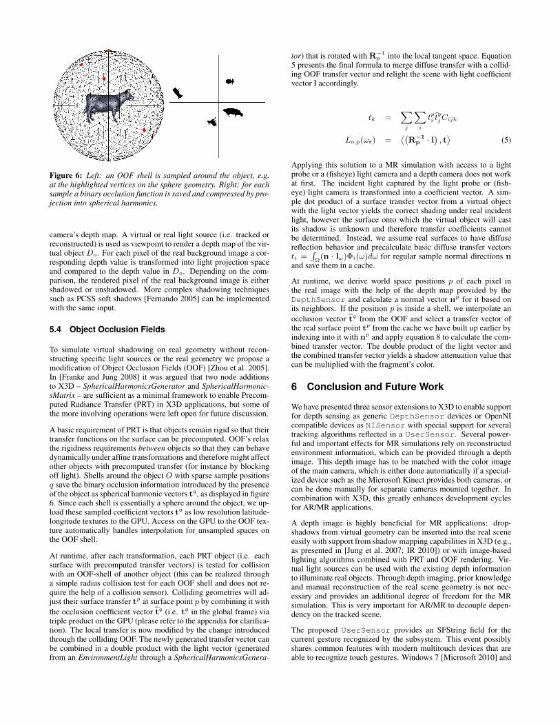
Figure 6: Left: an OOF shell is sampled around the object, e.g.at the highlighted vertices on the sphere geometry. Right: for eachsample a binary occlusion function is saved and compressed by pro-jection into spherical harmonics.
camera’s depth map. A virtual or real light source (i.e. tracked orreconstructed) is used as viewpoint to render a depth map of the vir-tual object Do. For each pixel of the real background image a cor-responding depth value is transformed into light projection spaceand compared to the depth value in Do. Depending on the com-parison, the rendered pixel of the real background image is eithershadowed or unshadowed. More complex shadowing techniquessuch as PCSS soft shadows [Fernando 2005] can be implementedwith the same input.
5.4 Object Occlusion Fields
To simulate virtual shadowing on real geometry without recon-structing specific light sources or the real geometry we propose amodification of Object Occlusion Fields (OOF) [Zhou et al. 2005].In [Franke and Jung 2008] it was argued that two node additionsto X3D – SphericalHarmonicsGenerator and SphericalHarmonic-sMatrix – are sufficient as a minimal framework to enable Precom-puted Radiance Transfer (PRT) in X3D applications, but some ofthe more involving operations were left open for future discussion.
A basic requirement of PRT is that objects remain rigid so that theirtransfer functions on the surface can be precomputed. OOF’s relaxthe rigidness requirements between objects so that they can behavedynamically under affine transformations and therefore might affectother objects with precomputed transfer (for instance by blockingoff light). Shells around the object O with sparse sample positionsq save the binary occlusion information introduced by the presenceof the object as spherical harmonic vectors tq , as displayed in figure6. Since each shell is essentially a sphere around the object, we up-load these sampled coefficient vectors tq as low resolution latitude-longitude textures to the GPU. Access on the GPU to the OOF tex-ture automatically handles interpolation for unsampled spaces onthe OOF shell.
At runtime, after each transformation, each PRT object (i.e. eachsurface with precomputed transfer vectors) is tested for collisionwith an OOF-shell of another object (this can be realized througha simple radius collision test for each OOF shell and does not re-quire the help of a collision sensor). Colliding geometries will ad-just their surface transfer tp at surface point p by combining it withthe occlusion coefficient vector tq (i.e. tq in the global frame) viatriple product on the GPU (please refer to the appendix for clarifica-tion). The local transfer is now modified by the change introducedthrough the colliding OOF. The newly generated transfer vector canbe combined in a double product with the light vector (generatedfrom an EnvironmentLight through a SphericalHarmonicsGenera-
tor) that is rotated with R−1p into the local tangent space. Equation
5 presents the final formula to merge diffuse transfer with a collid-ing OOF transfer vector and relight the scene with light coefficientvector l accordingly.
tk =∑j
∑i
tpi tqjCijk
Lo,p(ωr) =⟨(R−1
p · l), t⟩
(5)
Applying this solution to a MR simulation with access to a lightprobe or a (fisheye) light camera and a depth camera does not workat first. The incident light captured by the light probe or (fish-eye) light camera is transformed into a coefficient vector. A sim-ple dot product of a surface transfer vector from a virtual objectwith the light vector yields the correct shading under real incidentlight, however the surface onto which the virtual object will castits shadow is unknown and therefore transfer coefficients cannotbe determined. Instead, we assume real surfaces to have diffusereflection behavior and precalculate basic diffuse transfer vectorsti =
∫Ω
(n · lω)Φi(ω)dω for regular sample normal directions nand save them in a cache.
At runtime, we derive world space positions p of each pixel inthe real image with the help of the depth map provided by theDepthSensor and calculate a normal vector np for it based onits neighbors. If the position p is inside a shell, we interpolate anocclusion vector tq from the OOF and select a transfer vector ofthe real surface point tp from the cache we have built up earlier byindexing into it with np and apply equation 8 to calculate the com-bined transfer vector. The double product of the light vector andthe combined transfer vector yields a shadow attenuation value thatcan be multiplied with the fragment’s color.
6 Conclusion and Future Work
We have presented three sensor extensions to X3D to enable supportfor depth sensing as generic DepthSensor devices or OpenNIcompatible devices as NISensor with special support for severaltracking algorithms reflected in a UserSensor. Several power-ful and important effects for MR simulations rely on reconstructedenvironment information, which can be provided through a depthimage. This depth image has to be matched with the color imageof the main camera, which is either done automatically if a special-ized device such as the Microsoft Kinect provides both cameras, orcan be done manually for separate cameras mounted together. Incombination with X3D, this greatly enhances development cyclesfor AR/MR applications.
A depth image is highly beneficial for MR applications: drop-shadows from virtual geometry can be inserted into the real sceneeasily with support from shadow mapping capabilities in X3D (e.g.,as presented in [Jung et al. 2007; IR 2010]) or with image-basedlighting algorithms combined with PRT and OOF rendering. Vir-tual light sources can be used with the existing depth informationto illuminate real objects. Through depth imaging, prior knowledgeand manual reconstruction of the real scene geometry is not nec-essary and provides an additional degree of freedom for the MRsimulation. This is very important for AR/MR to decouple depen-dency on the tracked scene.
The proposed UserSensor provides an SFString field for thecurrent gesture recognized by the subsystem. This event possiblyshares common features with modern multitouch devices that areable to recognize touch gestures. Windows 7 [Microsoft 2010] and
Qt [Nokia 2010] for instance already have several gesture recogni-tion algorithms implemented, such as zooming, panning, rotationor selecting. For single user interaction a common event systemmight be more consistent for the application developer.
References
AKENINE-MOLLER, T., HAINES, E., AND HOFFMANN, N. 2008.Real-Time Rendering, 3 ed. AK Peters, Wellesley, MA.
ART, 2008. Artoolkit. http://www.hitl.washington.edu/artoolkit/.
BECKER, M., BLESER, G., PAGANI, A., STRICKER, D., ANDWUEST, H. 2007. An architecture for prototyping and applica-tion development of visual tracking systems. In Capture, Trans-mission and Display of 3D Video (Proc. of 3DTV-CON 07).
BEHR, J., DAHNE, P., AND ROTH, M. 2004. Utilizing X3D forimmersive environments. In Web3D ’04: Proc. of the ninth int.conf. on 3D Web technology, ACM Press, NY, USA, 71–78.
BEHR, J., KNOEPFLE, C., AND PATRICK, D. 2005. A scalablesensor approach for immersive and desktop VR Application. InHCI/VR International.
BITMANAGEMENT, 2002. Drawgroup & dra-wop. http://www.bitmanagement.de/ devel-oper/contact/examples/multitexture/drawgroup.html.
BLESER, G., WUEST, H., AND STRICKER, D. 2006. Online cam-era pose estimation in partially known and dynamic scenes. InISMAR 2006 : Proc. of the Fourth IEEE and ACM Int. Sympo-sium on Mixed and Augmented Reality, IEEE Computer Society,Los Alamitos, Calif., 56–65.
CALIBRATIONTOOLBOX, G. C., 2011.Gml camera calibration toolbox.http://graphics.cs.msu.ru/en/science/research/calibration/cpp.
CANUTESCU, A. A., AND DUNBRACK, R. L. 2003. Cyclic co-ordinate descent: A robotics algorithm for protein loop closure.Protein Science 12, 963–972.
DEBEVEC, P. 1998. Rendering synthetic objects into real scenes:Bridging traditional and image-based graphics with global illu-mination and high dynamic range photography. In Proc. of SIG-GRAPH 98, CG Proc., Annual Conf. Series, 189–198.
DEBEVEC, P. 2005. A median cut algorithm for light probesampling. In SIGGRAPH ’05: ACM SIGGRAPH 2005 Posters,ACM, New York, USA, 66.
DIEFENBACH, P. J., AND BADLER, N. I. 1997. Multi-passpipeline rendering: realism for dynamic environments. In I3D’97: Proceedings of the 1997 symposium on Interactive 3Dgraphics, ACM, New York, NY, USA, 59–70.
ENGELHARD, N., 2010. KinectAutoCalibration.https://github.com/NikolasE/KinectAutoCalibration.
FERNANDO, R. 2005. Percentage-closer soft shadows. In SIG-GRAPH ’05: Sketches, ACM Press, New York, USA, 35.
FORSYTH, D. A., AND PONCE, J. 2002. Computer Vision: AModern Approach. Prentice Hall Professional Technical Refer-ence.
FRANKE, T., AND JUNG, Y. 2008. Precomputed radiance trans-fer for X3D based mixed reality applications. In ProceedingsWeb3D 2008: 13th International Conference on 3D Web Tech-nology, ACM Press, New York, USA, S. Spencer, Ed., 7–10.
IR, 2010. Instant Reality. http://www.instantreality.org/.
JACOBS, K., AND LOSCOS, C. 2004. Classification of IlluminationMethods for Mixed Reality. In Eurographics 2004 - State of theArt Reports, Eurographics Association, 95–118.
JUNG, Y., FRANKE, T., DAHNE, P., AND BEHR, J. 2007. Enhanc-ing X3D for advanced MR appliances. In Proceedings Web3D’07, ACM Press, NY, USA, 27–36.
JUNG, Y., WAGNER, S., BEHR, J., JUNG, C., AND FELLNER,D. W. 2010. Storyboarding and pre-visualization with x3d. InProc. Web3D 2010: 15th Intl. Conference on 3D Web Technol-ogy, ACM Press, New York, USA, S. Spencer, Ed., 73–81.
KAHN, S., WUEST, H., STRICKER, D., AND FELLNER, D. W.2010. 3D discrepancy check and visualization via augmentedreality. In 9th IEEE International Symposium on Mixed and Aug-mented Reality (ISMAR), 241–242.
KAMBURELIS, M. 2010. Shadow maps and projective texturingin x3d. In Proceedings Web3D ’10, ACM, New York, NY, USA,17–26.
KOLB, A., BARTH, E., KOCH, R., AND LARSEN, R. 2009. Time-of-flight sensors in computer graphics. In EG 2009 - State of theArt Reports, Eurographics Association, M. Pauly and G. Greiner,Eds., 119–134.
KUHTREIBER, P. 2010. Brdf approximation and estimation foraugmented reality. Tech. rep., Institute of Computer Graphicsand Algorithms, Vienna University of Technology.
LEE, G., 2009. Supporting mixed re-ality visualization in x3d standards.http://web3d.org/membership/login/groups/Korea%20Web3D%20Forum/20090707-MR-Web3D-eng.pdf.
MADSEN, C. B., AND LAURSEN, R. E. 2007. A scalable gpu-based approach to shading and shadowing for photorealistic real-time augmented reality. In GRAPP 2007: Proceedings, IN-STICC Press, 252–261.
MICROSOFT, 2010. Windows touch ges-tures overview. http://msdn.microsoft.com/en-us/library/dd940543%28v=vs.85%29.aspx.
NG, R., RAMAMOORTHI, R., AND HANRAHAN, P. 2004. Tripleproduct wavelet integrals for all-frequency relighting. ACMTrans. Graph. 23, 3, 477–487.
NOKIA, 2010. Qt – cross-platform application and UI framework.http://qt.nokia.com/.
OCTAGA, 2009. Octaga – bringing enterprise data to life.http://www.octaga.com/.
OGGIER, T., LUSTENBERGER, F., AND BLANC, N. 2006. Minia-ture 3D ToF Camera for Real-Time Imaging. In Perception andInteractive Technologies, 212–216.
OPENCV, 2009. Opencv wiki.http://opencv.willowgarage.com/wiki/.
OPENNI, 2011. Openni framework. http://www.openni.org/.
REEVES, W. T., SALESIN, D. H., AND COOK, R. L. 1987. Ren-dering antialiased shadows with depth maps. In SIGGRAPH ’87,ACM Press, 283–291.
SCHILLER, I., BARTCZAK, B., KELLNER, F., AND KOCH, R.2010. Increasing realism and supporting content planning for
dynamic scenes in a mixed reality system incorporating a time-of-flight camera. Journal of Virtual Reality and Broadcasting7(2010), CVMP 2008 Special Issue no. 4.
SHI, J., AND TOMASI, C. 1994. Good features to track. InIEEE Conference on Computer Vision and Pattern Recognition(CVPR’94), 593–600.
SUDARSKY, S. 2001. Generating dynamic shadows for virtualreality applications. In IV ’01: Proceedings of the Fifth Interna-tional Conference on Information Visualisation, IEEE ComputerSociety, Washington, DC, USA, 595.
WEB3DCONSORTIUM, 2008. H-anim.http://www.web3d.org/x3d/specifications/ISO-IEC-19775-1.2-X3D-AbstractSpecification/Part01/components/hanim.html.
WEB3DCONSORTIUM, 2008. X3D.http://www.web3d.org/x3d/specifications/.
WUEST, H. 2008. Efficient Line and Patch Feature Characteri-zation and Management for Real-time Camera Tracking. PhDthesis, TU Darmstadt.
ZHOU, K., HU, Y., LIN, S., GUO, B., AND SHUM, H.-Y. 2005.Precomputed shadow fields for dynamic scenes. ACM Trans.Graph. 24, 3, 1196–1201.
Appendix
In this section, we shortly introduce the term triple products. Giventhree functions O(x), T (x) and E(x) = O(x)T (x) on a domainΩ, coefficients for any given basis Φ can be calculated with
Oi =
∫Ω
O(x)Φi(x)dx (6)
Ti =
∫Ω
T (x)Φi(x)dx (7)
and coefficients for E(x) are derived in the manner of equation 8,where i, j and k are indices of the basis components.
Ei =
∫Ω
Φi(x)E(x)dx =
∫Ω
Φi(x) (O(x)T (x)) dx
=
∫Ω
Φi(x)
(∑j
OjΦj(x)
)(∑k
TkΦk(x)
)dx
=∑j
∑k
OjTk
∫Ω
Φi(x)Φj(x)Φk(x)dx
=∑j
∑k
OjTkCijk (8)
=∑j
OjTij (9)
The term Cijk denotes a triple product integral or tripling coef-ficient. For spherical harmonics these values correspond to thewell studied Clebsch-Gordan coefficients, but there is no generalformula to analytically evaluate these coefficients for any basis Φ.Haar Wavelet tripling coefficients are presented in [Ng et al. 2004].Depending on the method of calculation, surface transfer for anypoint p can be saved as either a transfer vector T or a transfer ma-trix T, as shown in equation 9.


![Using Socially Expressive Mixed Reality Arms for Enhancing ... · robots–embodiment and physical affordances [13]–as well as the positive aspects of mixed reality–overcoming](https://img.pdfslide.net/doc/110x75/5fac978850ef6442967bc4a7/using-socially-expressive-mixed-reality-arms-for-enhancing-robotsaembodiment.jpg)