Embed Size (px)
Citation preview

ENNISKILLEN CHPPROCESS
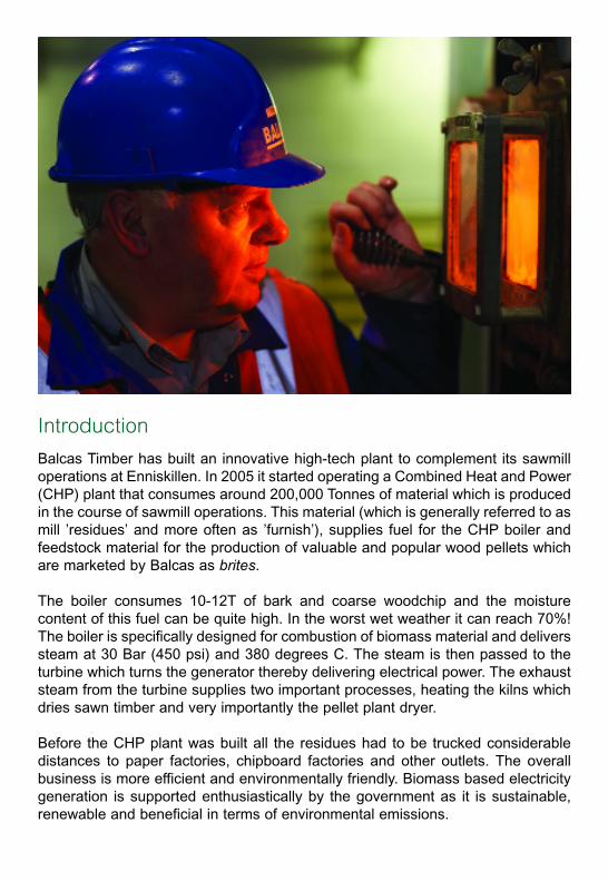
Balcas Timber has built an innovative high-tech plant to complement its sawmilloperations at Enniskillen. In 2005 it started operating a Combined Heat and Power(CHP) plant that consumes around 200,000 Tonnes of material which is producedin the course of sawmill operations. This material (which is generally referred to asmill ’residues’ and more often as ’furnish’), supplies fuel for the CHP boiler andfeedstock material for the production of valuable and popular wood pellets whichare marketed by Balcas as brites.
The boiler consumes 10-12T of bark and coarse woodchip and the moisturecontent of this fuel can be quite high. In the worst wet weather it can reach 70%!The boiler is specifically designed for combustion of biomass material and deliverssteam at 30 Bar (450 psi) and 380 degrees C. The steam is then passed to theturbine which turns the generator thereby delivering electrical power. The exhauststeam from the turbine supplies two important processes, heating the kilns whichdries sawn timber and very importantly the pellet plant dryer.
Before the CHP plant was built all the residues had to be trucked considerabledistances to paper factories, chipboard factories and other outlets. The overallbusiness is more efficient and environmentally friendly. Biomass based electricitygeneration is supported enthusiastically by the government as it is sustainable,renewable and beneficial in terms of environmental emissions.
Introduction
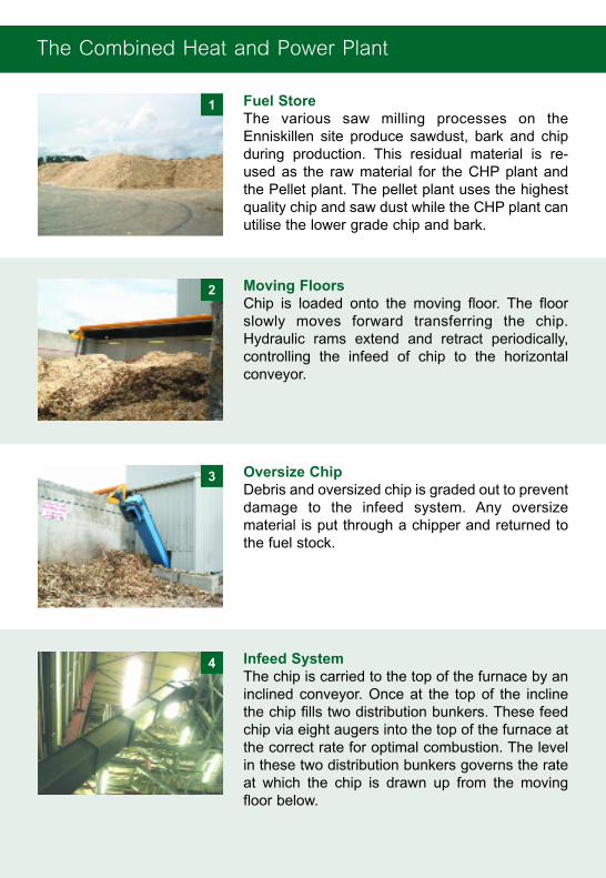
Fuel Store The various saw milling processes on theEnniskillen site produce sawdust, bark and chipduring production. This residual material is re-used as the raw material for the CHP plant andthe Pellet plant. The pellet plant uses the highestquality chip and saw dust while the CHP plant canutilise the lower grade chip and bark.
Moving Floors Chip is loaded onto the moving floor. The floorslowly moves forward transferring the chip.Hydraulic rams extend and retract periodically,controlling the infeed of chip to the horizontalconveyor.
Oversize ChipDebris and oversized chip is graded out to preventdamage to the infeed system. Any oversizematerial is put through a chipper and returned tothe fuel stock.
Infeed System The chip is carried to the top of the furnace by aninclined conveyor. Once at the top of the inclinethe chip fills two distribution bunkers. These feedchip via eight augers into the top of the furnace atthe correct rate for optimal combustion. The levelin these two distribution bunkers governs the rateat which the chip is drawn up from the movingfloor below.
The Combined Heat and Power Plant
1
2
3
4
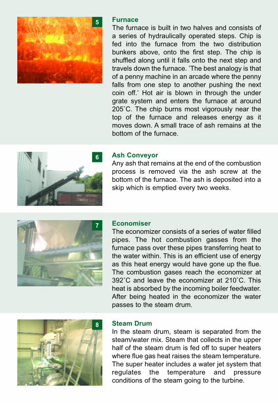
FurnaceThe furnace is built in two halves and consists ofa series of hydraulically operated steps. Chip isfed into the furnace from the two distributionbunkers above, onto the first step. The chip isshuffled along until it falls onto the next step andtravels down the furnace. ’The best analogy is thatof a penny machine in an arcade where the pennyfalls from one step to another pushing the nextcoin off.’ Hot air is blown in through the undergrate system and enters the furnace at around205˚C. The chip burns most vigorously near thetop of the furnace and releases energy as itmoves down. A small trace of ash remains at thebottom of the furnace.
Ash Conveyor Any ash that remains at the end of the combustionprocess is removed via the ash screw at thebottom of the furnace. The ash is deposited into askip which is emptied every two weeks.
EconomiserThe economizer consists of a series of water filledpipes. The hot combustion gasses from thefurnace pass over these pipes transferring heat tothe water within. This is an efficient use of energyas this heat energy would have gone up the flue.The combustion gases reach the economizer at392˚C and leave the economizer at 210˚C. Thisheat is absorbed by the incoming boiler feedwater.After being heated in the economizer the waterpasses to the steam drum.
Steam Drum In the steam drum, steam is separated from thesteam/water mix. Steam that collects in the upperhalf of the steam drum is fed off to super heaterswhere flue gas heat raises the steam temperature.The super heater includes a water jet system thatregulates the temperature and pressureconditions of the steam going to the turbine.
5
6
7
8
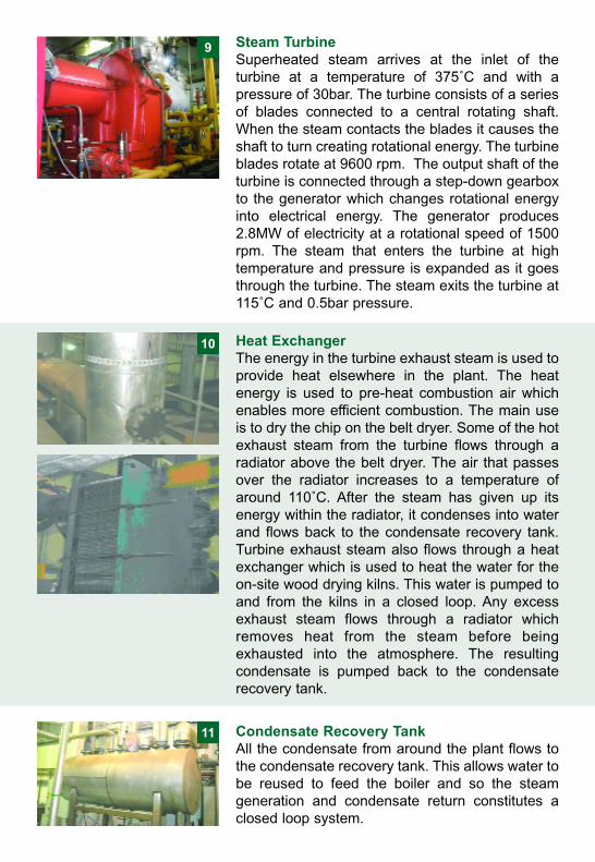
Steam Turbine Superheated steam arrives at the inlet of theturbine at a temperature of 375˚C and with apressure of 30bar. The turbine consists of a seriesof blades connected to a central rotating shaft.When the steam contacts the blades it causes theshaft to turn creating rotational energy. The turbineblades rotate at 9600 rpm. The output shaft of theturbine is connected through a step-down gearboxto the generator which changes rotational energyinto electrical energy. The generator produces2.8MW of electricity at a rotational speed of 1500rpm. The steam that enters the turbine at hightemperature and pressure is expanded as it goesthrough the turbine. The steam exits the turbine at115˚C and 0.5bar pressure.
Heat Exchanger The energy in the turbine exhaust steam is used toprovide heat elsewhere in the plant. The heatenergy is used to pre-heat combustion air whichenables more efficient combustion. The main useis to dry the chip on the belt dryer. Some of the hotexhaust steam from the turbine flows through aradiator above the belt dryer. The air that passesover the radiator increases to a temperature ofaround 110˚C. After the steam has given up itsenergy within the radiator, it condenses into waterand flows back to the condensate recovery tank.Turbine exhaust steam also flows through a heatexchanger which is used to heat the water for theon-site wood drying kilns. This water is pumped toand from the kilns in a closed loop. Any excessexhaust steam flows through a radiator whichremoves heat from the steam before beingexhausted into the atmosphere. The resultingcondensate is pumped back to the condensaterecovery tank.
Condensate Recovery Tank All the condensate from around the plant flows tothe condensate recovery tank. This allows water tobe reused to feed the boiler and so the steamgeneration and condensate return constitutes aclosed loop system.
9
10
11
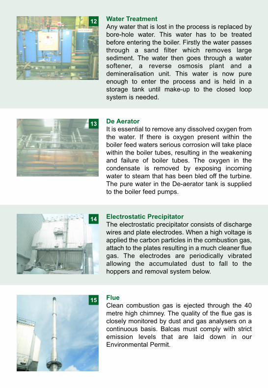
Water Treatment Any water that is lost in the process is replaced bybore-hole water. This water has to be treatedbefore entering the boiler. Firstly the water passesthrough a sand filter which removes largesediment. The water then goes through a watersoftener, a reverse osmosis plant and ademineralisation unit. This water is now pureenough to enter the process and is held in astorage tank until make-up to the closed loopsystem is needed.
De AeratorIt is essential to remove any dissolved oxygen fromthe water. If there is oxygen present within theboiler feed waters serious corrosion will take placewithin the boiler tubes, resulting in the weakeningand failure of boiler tubes. The oxygen in thecondensate is removed by exposing incomingwater to steam that has been bled off the turbine.The pure water in the De-aerator tank is suppliedto the boiler feed pumps.
Electrostatic PrecipitatorThe electrostatic precipitator consists of dischargewires and plate electrodes. When a high voltage isapplied the carbon particles in the combustion gas,attach to the plates resulting in a much cleaner fluegas. The electrodes are periodically vibratedallowing the accumulated dust to fall to thehoppers and removal system below.
FlueClean combustion gas is ejected through the 40metre high chimney. The quality of the flue gas isclosely monitored by dust and gas analysers on acontinuous basis. Balcas must comply with strictemission levels that are laid down in ourEnvironmental Permit.
12
13
14
15
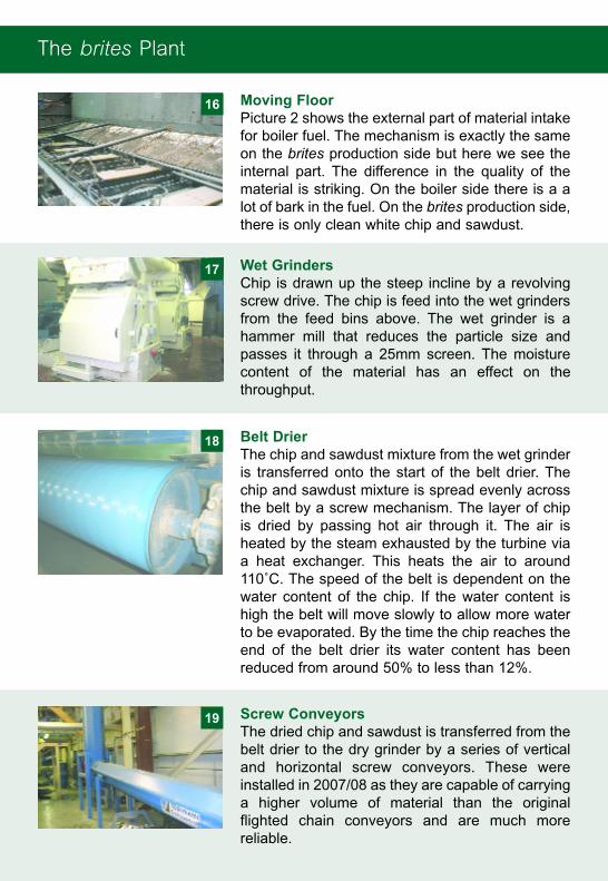
Moving Floor Picture 2 shows the external part of material intakefor boiler fuel. The mechanism is exactly the sameon the brites production side but here we see theinternal part. The difference in the quality of thematerial is striking. On the boiler side there is a alot of bark in the fuel. On the brites production side,there is only clean white chip and sawdust.
Wet GrindersChip is drawn up the steep incline by a revolvingscrew drive. The chip is feed into the wet grindersfrom the feed bins above. The wet grinder is ahammer mill that reduces the particle size andpasses it through a 25mm screen. The moisturecontent of the material has an effect on thethroughput.
Belt Drier The chip and sawdust mixture from the wet grinderis transferred onto the start of the belt drier. Thechip and sawdust mixture is spread evenly acrossthe belt by a screw mechanism. The layer of chipis dried by passing hot air through it. The air isheated by the steam exhausted by the turbine viaa heat exchanger. This heats the air to around110˚C. The speed of the belt is dependent on thewater content of the chip. If the water content ishigh the belt will move slowly to allow more waterto be evaporated. By the time the chip reaches theend of the belt drier its water content has beenreduced from around 50% to less than 12%.
Screw Conveyors The dried chip and sawdust is transferred from thebelt drier to the dry grinder by a series of verticaland horizontal screw conveyors. These wereinstalled in 2007/08 as they are capable of carryinga higher volume of material than the originalflighted chain conveyors and are much morereliable.
The brites Plant
16
17
18
19
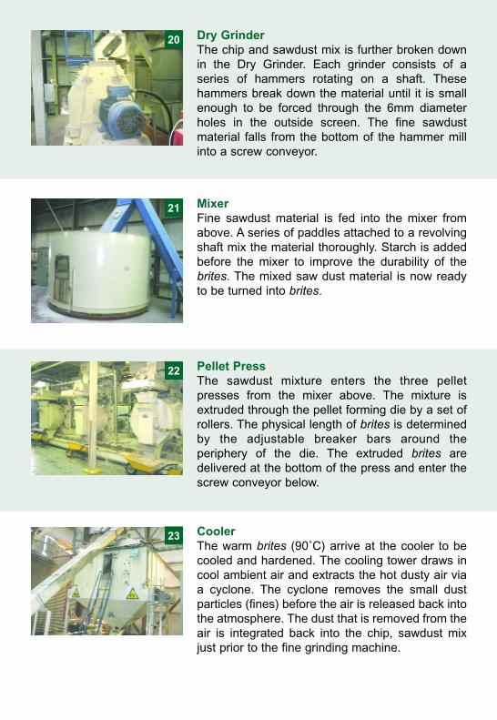
Dry GrinderThe chip and sawdust mix is further broken downin the Dry Grinder. Each grinder consists of aseries of hammers rotating on a shaft. Thesehammers break down the material until it is smallenough to be forced through the 6mm diameterholes in the outside screen. The fine sawdustmaterial falls from the bottom of the hammer millinto a screw conveyor.
MixerFine sawdust material is fed into the mixer fromabove. A series of paddles attached to a revolvingshaft mix the material thoroughly. Starch is addedbefore the mixer to improve the durability of thebrites. The mixed saw dust material is now readyto be turned into brites.
Pellet PressThe sawdust mixture enters the three pelletpresses from the mixer above. The mixture isextruded through the pellet forming die by a set ofrollers. The physical length of brites is determinedby the adjustable breaker bars around theperiphery of the die. The extruded brites aredelivered at the bottom of the press and enter thescrew conveyor below.
CoolerThe warm brites (90˚C) arrive at the cooler to becooled and hardened. The cooling tower draws incool ambient air and extracts the hot dusty air viaa cyclone. The cyclone removes the small dustparticles (fines) before the air is released back intothe atmosphere. The dust that is removed from theair is integrated back into the chip, sawdust mixjust prior to the fine grinding machine.
20
21
22
23
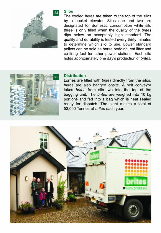
SilosThe cooled brites are taken to the top of the silosby a bucket elevator. Silos one and two aredesignated for domestic consumption while silothree is only filled when the quality of the britesdips below an acceptably high standard. Thequality and durability is tested every thirty minutesto determine which silo to use. Lower standardpellets can be sold as horse bedding, cat litter andco-firing fuel for other power stations. Each siloholds approximately one day’s production of brites.
DistributionLorries are filled with brites directly from the silos.brites are also bagged onsite. A belt conveyortakes brites from silo two into the top of thebagging unit. The brites are weighed into 10 kgportions and fed into a bag which is heat sealedready for dispatch. The plant makes a total of53,000 Tonnes of brites each year.
24
25
Can the generator supply all of Balcas electrical needs at Enniskillen?We can generate 2.7 Megawatts but when all the pellet plant and sawmill is fullon, we use 3.8 Megawatts. This means that some is still imported from the PowerNI Electricity grid. At weekends and during the night when some sawmills areshutdown, we generate more than we can use and so Balcas exports to the PowerNI Electricity grid.
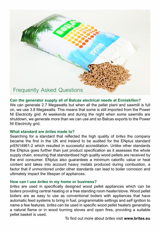
What standard are brites made to?Searching for a standard that reflected the high quality of brites the companybecame the first in the UK and Ireland to be audited for the ENplus standardprEN14961-2 which resulted in successful accreditation. Unlike other standardsthe ENplus goes further than just product specification as it assesses the wholesupply chain, ensuring that standardised high quality wood pellets are received bythe end consumer. ENplus also guarantees a minimum calorific value or heatcontent and takes into account heavy metals produced during combustion, afactor that if unmonitored under other standards can lead to boiler corrosion andultimately impact the lifespan of appliances.
How can I use brites in my home or business?brites are used in specifically designed wood pellet appliances which can beboilers providing central heating or a free standing room heater/stove. Wood pelletboilers are as easy to use as conventional boilers with appliances that haveautomatic feed systems to bring in fuel, programmable settings and self ignition toname a few features. brites can be used in specific wood pellet heaters generatinga natural flame or in wood burning stoves and open fires, providing a suitablepellet basket is used.
To find out more about brites visit www.brites.eu
Frequently Asked Questions