Embed Size (px)
Citation preview
ENSC 427: COMMUNICATION
NETWORKS Simulation of ZigBee Wireless Sensor Networks
Final Report Spring 2012
Mehran Ferdowsi
ENSC 427: COMMUNICATION NETWORKS
i
Table of Contents
1. Introduction ..........................................................................................................................2
2. Project Scope..........................................................................................................................2
3. ZigBee Overview...................................................................................................................2
3.1. ZigBee Specifications ...................................................................................................... 2
3.2. ZigBee Layers .................................................................................................................. 3
3.2.1. Application Layer .................................................................................................. 3
3.2.2. ZigBee Device Objective ......................................................................................... 4
3.2.3. Network Layer ....................................................................................................... 4
3.2.4. Medium Access Control Layer ............................................................................. 4
3.2.5. Physical Layer ......................................................................................................... 4
3.3. ZigBee Hardware .............................................................................................................4
3.3.1. Coordinator .................................................................................................................. 5
3.3.2. Router ........................................................................................................................... 5
3.3.3. End device..................................................................................................................... 5
3.4. Network Topology ............................................................................................................5
3.4.1. Star Topology ............................................................................................................... 6
3.4.2. Mesh Topology ............................................................................................................. 6
3.4.3. Tree Topology .............................................................................................................. 6
4. ZigBee Network Simulation Using OPNET 16 ..........................................................7
4.1. ZigBee Model Properties ............................................................................................... 7
4.2. Small scale WSN .............................................................................................................. 8
4.3. Medium scale WSN ........................................................................................................ 9
4.4. Large scale WSN .......................................................................................................... 10
5. Simulation Results .............................................................................................................10
5.1. Small scale WSN ............................................................................................................ 10
5.2. Medium scale WSN ...................................................................................................... 10
5.3. Large scale WSN .......................................................................................................... 11
ENSC 427: COMMUNICATION NETWORKS
ii
6. Discussion and Conclusion ..............................................................................................14
6.1. Simulation result conclusion ....................................................................................... 14
6.2. Future work .................................................................................................................... 15
7. References .............................................................................................................................16
ENSC 427: COMMUNICATION NETWORKS
1
1. Abstract
The ZigBee protocol stack based on IEEE 802.15.4 offers a practical, cost-effective solution for low-cost and
low power consumption WPANs. These characteristics make ZigBee networks the ideal candidate for Wireless
Sensor Networks in many applications such as Commercial Building and Home Automation, Medical
equipment monitoring and Industrial control. Latency and reliability are significant performance measurements
in sensor networks; this project focuses on simulating and assessing a Wireless Sensor Network implementing
the ZigBee protocol using the OPNET 16 network simulation tool.
ENSC 427: COMMUNICATION NETWORKS
2
1. Introduction
The use of Wireless Personal Area Networks has been steadily increasing in recent years. The inconvenience
and logistical concerns of laying wires for a communication network lay the ground for a much more appealing
technologies incorporating wireless transmission. Removing the constraints of the physical installation of wires,
wireless solutions provide diversity and in many applications can reduce cost.
ZigBee is based on the IEEE 802.15.4 standard along with other protocols like Wi-Fi and Bluetooth. ZigBee
operates in the industrial, scientific and medical (ISM) radio band, specifically at 2.4 GHz internationally and
868 MHz or 915 MHz in specific parts of the world. ZigBee differs from Wi-Fi and Bluetooth technologies; in
that is was mainly developed for low-rate WPAN’s (LR-WPAN). Technology defined by the ZigBee
specification is intended to be much simpler and less expensive than that of other WPANs. The simplicity and
cost of ZigBee networks makes them a great candidate for wireless control and monitoring applications.
The ZigBee protocol can support over 64,000 nodes and can operate in three network topologies: Star, Tree and
Mesh. The large amount of supported nodes is another appealing characteristic, specifically in industrial
applications.
2. Project Scope
The primary goal of this project is to investigate and evaluate the ZigBee protocol using OPNET simulation
tool. Specifically, this project will analyse ZigBee wireless sensor networks (WSN) in both star and mesh
topologies. For both topologies, the number of transmitting nodes and the physical size of the network will be
altered to understand their effects. The goal is to emulate a WSN, hence, the physical expansion of the network
(to mimic industrial applications) and the addition of numerous nodes to imitate various sensors.
3. ZigBee Overview
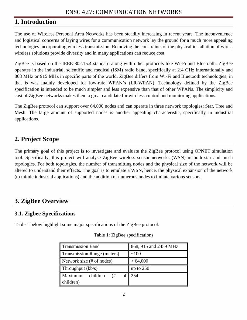
3.1. Zigbee Specifications
Table 1 below highlight some major specifications of the ZigBee protocol.
Table 1: ZigBee specifications
Transmission Band 868, 915 and 2459 MHz
Transmission Range (meters) ~100
Network size (# of nodes) > 64,000
Throughput (kb/s) up to 250
Maximum children (# of
children)
254
ENSC 427: COMMUNICATION NETWORKS
3
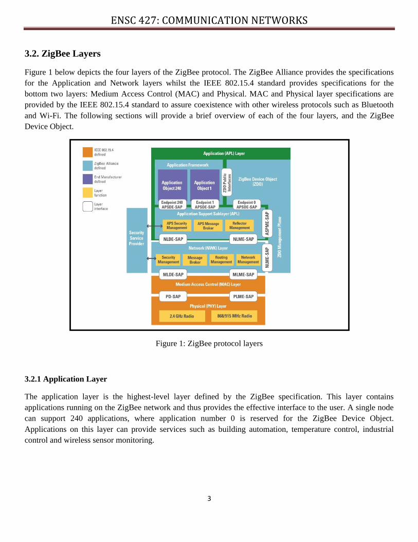
3.2. ZigBee Layers
Figure 1 below depicts the four layers of the ZigBee protocol. The ZigBee Alliance provides the specifications
for the Application and Network layers whilst the IEEE 802.15.4 standard provides specifications for the
bottom two layers: Medium Access Control (MAC) and Physical. MAC and Physical layer specifications are
provided by the IEEE 802.15.4 standard to assure coexistence with other wireless protocols such as Bluetooth
and Wi-Fi. The following sections will provide a brief overview of each of the four layers, and the ZigBee
Device Object.
Figure 1: ZigBee protocol layers
3.2.1 Application Layer
The application layer is the highest-level layer defined by the ZigBee specification. This layer contains
applications running on the ZigBee network and thus provides the effective interface to the user. A single node
can support 240 applications, where application number 0 is reserved for the ZigBee Device Object.
Applications on this layer can provide services such as building automation, temperature control, industrial
control and wireless sensor monitoring.
ENSC 427: COMMUNICATION NETWORKS
4
3.2.2 ZigBee Device Object
The ZigBee device object represents the ZigBee node type of the device; defining the nodes role on the
network. It is resident on all ZigBee nodes and provides generic ZigBee device functions. Since the ZigBee
Device object is present on all devices, it is a useful and interoperable way of managing and gathering system
properties.
3.2.3 Network Layer
As depicted in figure 1 the network layer is responsible for network management and addressing, message
routing, route discovery as well as security features. The ZigBee Alliance defines this layer.
3.2.4. Medium Access Control Layer
The MAC layer determines source and destination addressing of frames and is extracted from the IEEE
802.15.4 standard. To provide reliable data transfer, this layer provides multiple access control in the form of
Carrier Sense Multiple Access and Collision Avoidance (CSMA/CA).
3.2.5. Physical Layer
The physical layer is provided by the IEEE 802.15.4 standard. The physical layer is ultimately responsible for
providing the data transmission service. This layer manages the physical RF transceiver; it performs channel
selection as well as energy and signal management routines. As well, this layer exchanges data with the MAC
layer above it. The physical transmission of radio waves occurs in different frequency bands which are
mentioned in table 1. To avoid radio interference in order to support coexistence with other wireless
technologies, the physical layer allows for channel selection.
3.3. ZigBee Hardware
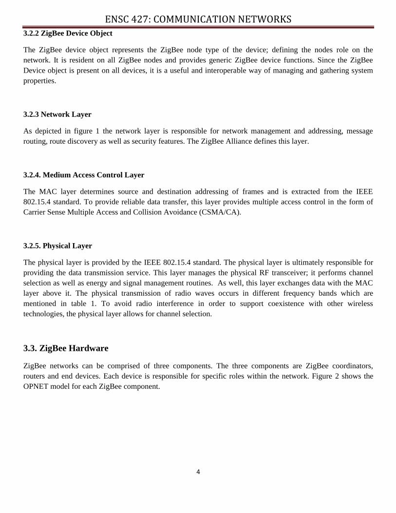
ZigBee networks can be comprised of three components. The three components are ZigBee coordinators,
routers and end devices. Each device is responsible for specific roles within the network. Figure 2 shows the
OPNET model for each ZigBee component.
ENSC 427: COMMUNICATION NETWORKS
5
Figure 2: OPNET ZigBee models
3.3.1. Coordinator
For every ZigBee network there must be one and only one coordinator. The coordinators responsibilities include
initializing the network, selecting the transmission channel and permitting other ZigBee nodes to connect to its
network. A ZigBee coordinator can also route traffic within a network.
3.3.2 Router
A ZigBee router is responsible for message routing within a network. Not all networks require a router because
traffic can travel directly from an end device to a coordinator or even from end device to another end device by
using routing features of a coordinator. A routing device can also act as an end device; however, its routing
capabilities would be inactive. A router can have child nodes connected to it depending on the network topology
implemented.
3.3.3. End device
ZigBee end devices connect to routers or coordinators in a network but cannot have other devices connect to the
ZigBee network by piggybacking of its connection. End devices are the end points of a ZigBee network and
contain limited functionality to talk to parent nodes (coordinator or a router). Since they do not have routing
responsibilities and can enter low-power sleep modes during periods of inactivity, ZigBee end devices have
substantial battery lives. Due to its limited functionality, end devices impose limited memory footprints and can
therefore be less expensive to manufacture than a router or a coordinator.
3.4. Network Topology
ZigBee networks support operating in Star, Tree, and Mesh topologies. Depending on the application of the
ZigBee network, topology selection can drastically affect the behaviour of the network. For this reason, proper
topology selection is very important.
ENSC 427: COMMUNICATION NETWORKS
6
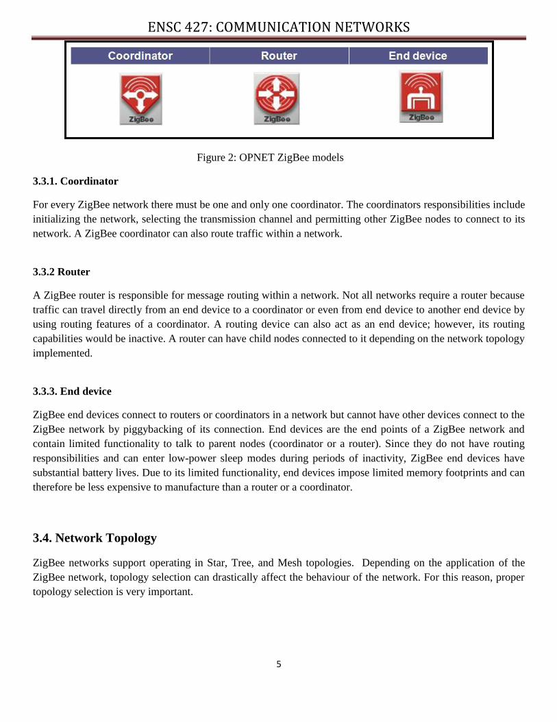
3.4.1. Star Topology
The star topology is the simplest of the three and is depicted in figure 3. Its simplicity is very attractive but also
presents certain drawbacks. Since the coordinator is at the center of the star all incoming data from end devices
destined for other end devices must pass through this node. As well, the coordinator can be the destination of
outgoing traffic from end devices, for example, in a wireless sensor network where sensor traffic is sent to the
coordinator for logging and/or processing.
Figure 3: Star topology
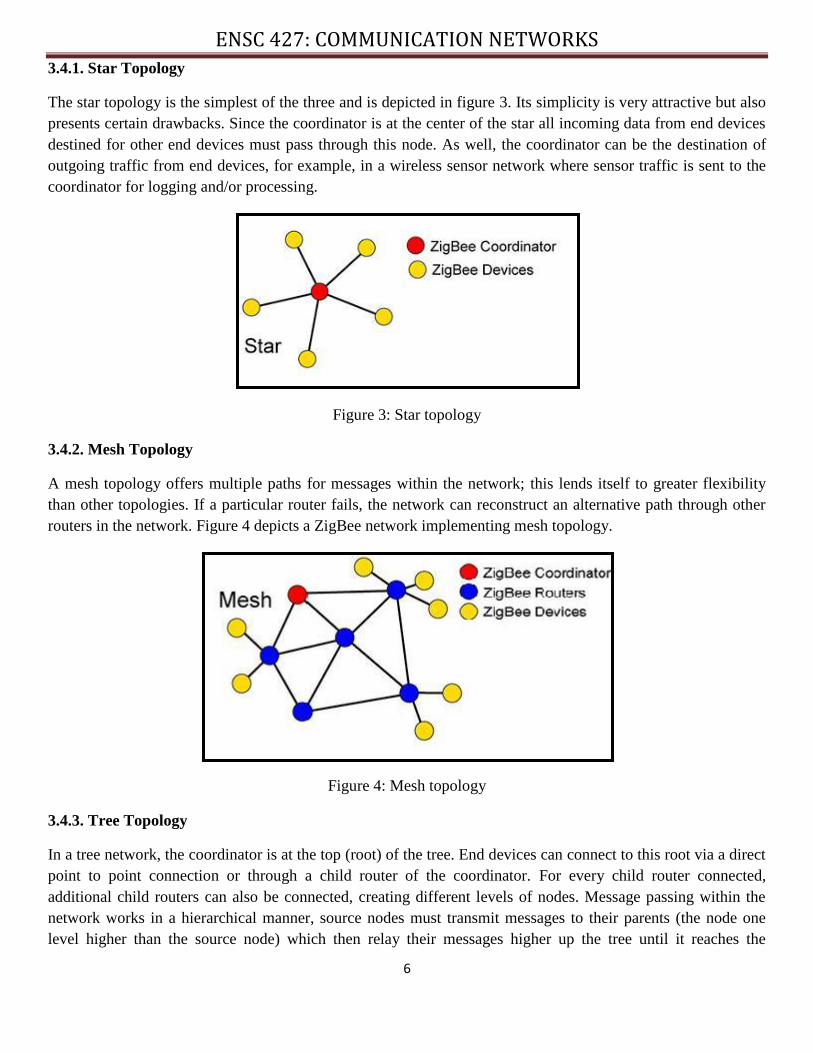
3.4.2. Mesh Topology
A mesh topology offers multiple paths for messages within the network; this lends itself to greater flexibility
than other topologies. If a particular router fails, the network can reconstruct an alternative path through other
routers in the network. Figure 4 depicts a ZigBee network implementing mesh topology.
Figure 4: Mesh topology
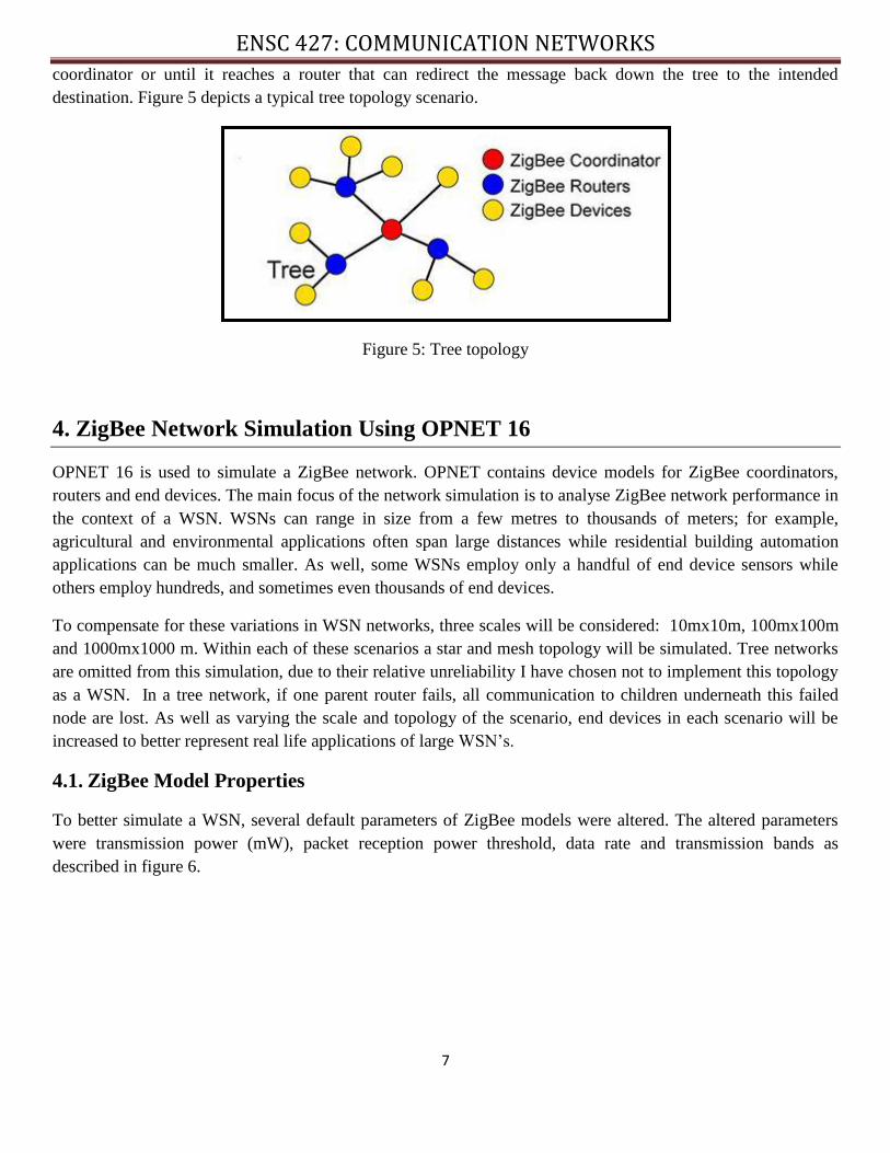
3.4.3. Tree Topology
In a tree network, the coordinator is at the top (root) of the tree. End devices can connect to this root via a direct
point to point connection or through a child router of the coordinator. For every child router connected,
additional child routers can also be connected, creating different levels of nodes. Message passing within the
network works in a hierarchical manner, source nodes must transmit messages to their parents (the node one
level higher than the source node) which then relay their messages higher up the tree until it reaches the
ENSC 427: COMMUNICATION NETWORKS
7
coordinator or until it reaches a router that can redirect the message back down the tree to the intended
destination. Figure 5 depicts a typical tree topology scenario.
Figure 5: Tree topology
4. ZigBee Network Simulation Using OPNET 16
OPNET 16 is used to simulate a ZigBee network. OPNET contains device models for ZigBee coordinators,
routers and end devices. The main focus of the network simulation is to analyse ZigBee network performance in
the context of a WSN. WSNs can range in size from a few metres to thousands of meters; for example,
agricultural and environmental applications often span large distances while residential building automation
applications can be much smaller. As well, some WSNs employ only a handful of end device sensors while
others employ hundreds, and sometimes even thousands of end devices.
To compensate for these variations in WSN networks, three scales will be considered: 10mx10m, 100mx100m
and 1000mx1000 m. Within each of these scenarios a star and mesh topology will be simulated. Tree networks
are omitted from this simulation, due to their relative unreliability I have chosen not to implement this topology
as a WSN. In a tree network, if one parent router fails, all communication to children underneath this failed
node are lost. As well as varying the scale and topology of the scenario, end devices in each scenario will be
increased to better represent real life applications of large WSN’s.
4.1. ZigBee Model Properties
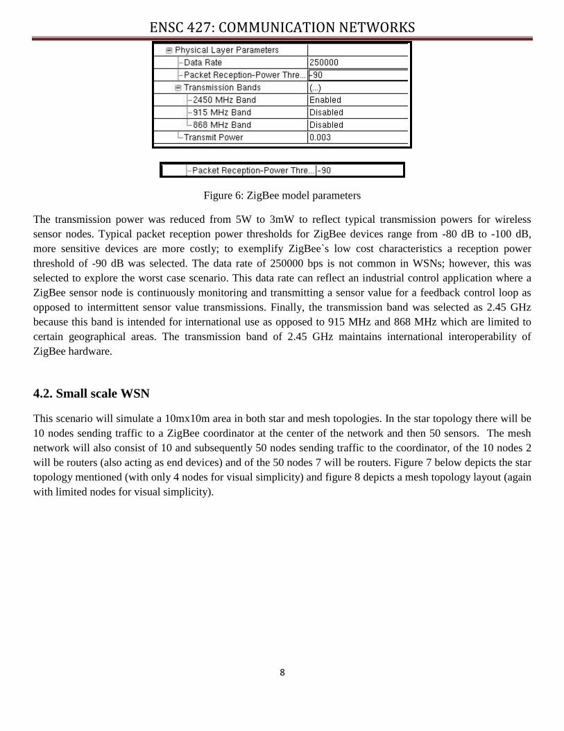
To better simulate a WSN, several default parameters of ZigBee models were altered. The altered parameters
were transmission power (mW), packet reception power threshold, data rate and transmission bands as
described in figure 6.
ENSC 427: COMMUNICATION NETWORKS
8
Figure 6: ZigBee model parameters
The transmission power was reduced from 5W to 3mW to reflect typical transmission powers for wireless
sensor nodes. Typical packet reception power thresholds for ZigBee devices range from -80 dB to -100 dB,
more sensitive devices are more costly; to exemplify ZigBee`s low cost characteristics a reception power
threshold of -90 dB was selected. The data rate of 250000 bps is not common in WSNs; however, this was
selected to explore the worst case scenario. This data rate can reflect an industrial control application where a
ZigBee sensor node is continuously monitoring and transmitting a sensor value for a feedback control loop as
opposed to intermittent sensor value transmissions. Finally, the transmission band was selected as 2.45 GHz
because this band is intended for international use as opposed to 915 MHz and 868 MHz which are limited to
certain geographical areas. The transmission band of 2.45 GHz maintains international interoperability of
ZigBee hardware.
4.2. Small scale WSN
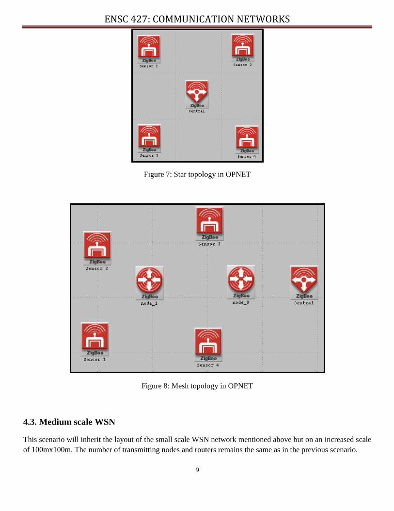
This scenario will simulate a 10mx10m area in both star and mesh topologies. In the star topology there will be
10 nodes sending traffic to a ZigBee coordinator at the center of the network and then 50 sensors. The mesh
network will also consist of 10 and subsequently 50 nodes sending traffic to the coordinator, of the 10 nodes 2
will be routers (also acting as end devices) and of the 50 nodes 7 will be routers. Figure 7 below depicts the star
topology mentioned (with only 4 nodes for visual simplicity) and figure 8 depicts a mesh topology layout (again
with limited nodes for visual simplicity).
ENSC 427: COMMUNICATION NETWORKS
9
Figure 7: Star topology in OPNET
Figure 8: Mesh topology in OPNET
4.3. Medium scale WSN
This scenario will inherit the layout of the small scale WSN network mentioned above but on an increased scale
of 100mx100m. The number of transmitting nodes and routers remains the same as in the previous scenario.
ENSC 427: COMMUNICATION NETWORKS
10
4.4. Large scale WSN
This scenario is 1000mx1000m large and employs both star and mesh networks. For the star network 10 and
250 transmitting nodes will be simulated. The mesh layout will implement 10, 50 and 250 transmitting nodes
with 2,7 and 27 routers respectively.
5. Simulation Results
5.1. Small scale WSN
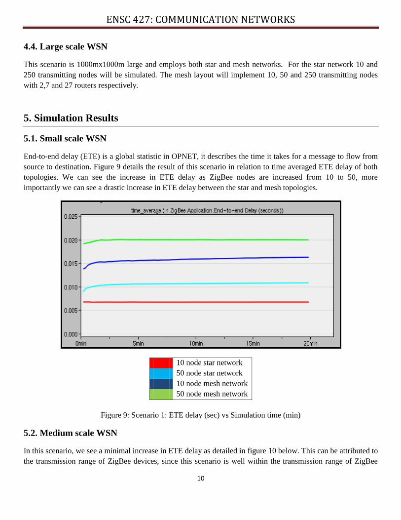
End-to-end delay (ETE) is a global statistic in OPNET, it describes the time it takes for a message to flow from
source to destination. Figure 9 details the result of this scenario in relation to time averaged ETE delay of both
topologies. We can see the increase in ETE delay as ZigBee nodes are increased from 10 to 50, more
importantly we can see a drastic increase in ETE delay between the star and mesh topologies.
10 node star network
50 node star network
10 node mesh network
50 node mesh network
Figure 9: Scenario 1: ETE delay (sec) vs Simulation time (min)
5.2. Medium scale WSN
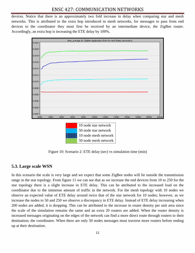
In this scenario, we see a minimal increase in ETE delay as detailed in figure 10 below. This can be attributed to
the transmission range of ZigBee devices, since this scenario is well within the transmission range of ZigBee
ENSC 427: COMMUNICATION NETWORKS
11
devices. Notice that there is an approximately two fold increase in delay when comparing star and mesh
networks. This is attributed to the extra hop introduced in mesh networks, for messages to pass from end
devices to the coordinator they must first be received by an intermediate device, the ZigBee router.
Accordingly, an extra hop is increasing the ETE delay by 100%.
10 node star network
50 node star network
10 node mesh network
50 node mesh network
Figure 10: Scenario 2: ETE delay (sec) vs simulation time (min)
5.3. Large scale WSN
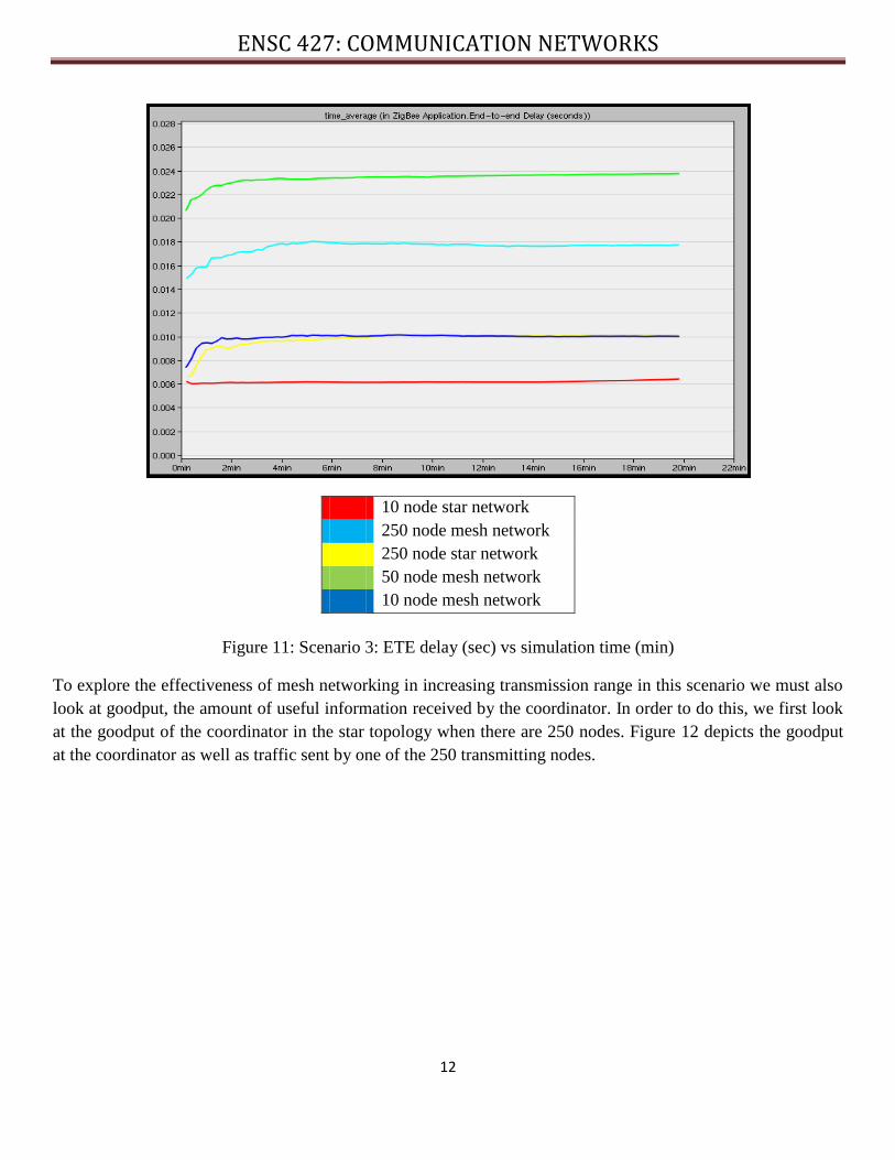
In this scenario the scale is very large and we expect that some ZigBee nodes will lie outside the transmission
range in the star topology. From figure 11 we can see that as we increase the end devices from 10 to 250 for the
star topology there is a slight increase in ETE delay. This can be attributed to the increased load on the
coordinator due to the immense amount of traffic in the network. For the mesh topology with 10 nodes we
observe an expected value of ETE delay around twice that of the star network for 10 nodes; however, as we
increase the nodes to 50 and 250 we observe a discrepancy in ETE delay. Instead of ETE delay increasing when
200 nodes are added, it is dropping. This can be attributed to the increase in router density per unit area since
the scale of the simulation remains the same and an extra 20 routers are added. When the router density is
increased messages originating on the edges of the network can find a more direct route through routers to their
destination; the coordinator. When there are only 50 nodes messages must traverse more routers before ending
up at their destination.
ENSC 427: COMMUNICATION NETWORKS
12
10 node star network
250 node mesh network
250 node star network
50 node mesh network
10 node mesh network
Figure 11: Scenario 3: ETE delay (sec) vs simulation time (min)
To explore the effectiveness of mesh networking in increasing transmission range in this scenario we must also
look at goodput, the amount of useful information received by the coordinator. In order to do this, we first look
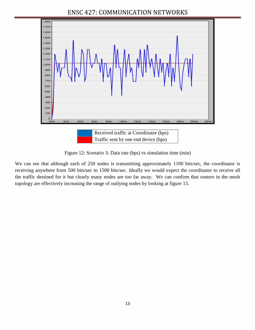
at the goodput of the coordinator in the star topology when there are 250 nodes. Figure 12 depicts the goodput
at the coordinator as well as traffic sent by one of the 250 transmitting nodes.
ENSC 427: COMMUNICATION NETWORKS
13
Received traffic at Coordinator (bps)
Traffic sent by one end device (bps)
Figure 12: Scenario 3: Data rate (bps) vs simulation time (min)
We can see that although each of 250 nodes is transmitting approximately 1100 bits/sec, the coordinator is
receiving anywhere from 500 bits/sec to 1500 bits/sec. Ideally we would expect the coordinator to receive all
the traffic destined for it but clearly many nodes are too far away. We can confirm that routers in the mesh
topology are effectively increasing the range of outlying nodes by looking at figure 13.
ENSC 427: COMMUNICATION NETWORKS
14
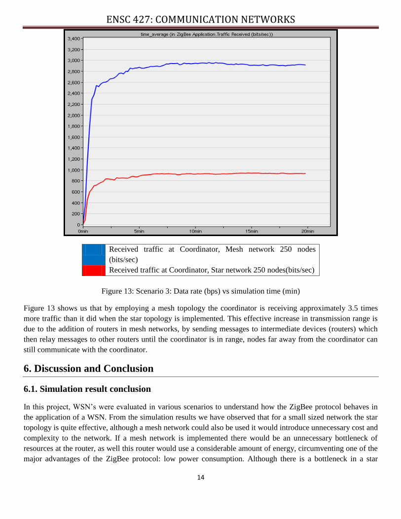
Received traffic at Coordinator, Mesh network 250 nodes
(bits/sec)
Received traffic at Coordinator, Star network 250 nodes(bits/sec)
Figure 13: Scenario 3: Data rate (bps) vs simulation time (min)
Figure 13 shows us that by employing a mesh topology the coordinator is receiving approximately 3.5 times
more traffic than it did when the star topology is implemented. This effective increase in transmission range is
due to the addition of routers in mesh networks, by sending messages to intermediate devices (routers) which
then relay messages to other routers until the coordinator is in range, nodes far away from the coordinator can
still communicate with the coordinator.
6. Discussion and Conclusion
6.1. Simulation result conclusion
In this project, WSN’s were evaluated in various scenarios to understand how the ZigBee protocol behaves in
the application of a WSN. From the simulation results we have observed that for a small sized network the star
topology is quite effective, although a mesh network could also be used it would introduce unnecessary cost and
complexity to the network. If a mesh network is implemented there would be an unnecessary bottleneck of
resources at the router, as well this router would use a considerable amount of energy, circumventing one of the
major advantages of the ZigBee protocol: low power consumption. Although there is a bottleneck in a star
ENSC 427: COMMUNICATION NETWORKS
15
network as well (coordinator) we assume that in a WSN this node is not operating via battery power due to its
data logging requirements. In the second scenario a medium sized WSN was simulated. Both star and mesh
networks performed similarly but the mesh network exhibited larger ETE delays. Depending on the specific
application of the WSN in a medium sized network, a star or mesh network can be appropriate. If ETE delay is
of utmost importance, for example, in industrial control applications it might be suitable to deploy a star
network to reduce ETE delay. Finally, we examined a large ZigBee WSN and concluded that a star topology is
not appropriate in this situation. By implementing a mesh topology it is possible to avoid transmission range
limitations of ZigBee end devices. This feature is extremely appealing, especially for WSN applications in
agricultural and environmental monitoring due to the typically large span of these networks.
6.2. Future work
Some future work that can be implemented is to physically construct a ZigBee network. I am currently working
on a Capstone project involving Bluetooth communication to relay sensor data to a central processing unit. In
the future I would like to explore implementing a ZigBee network instead of Bluetooth due to unfavorable
power consumption characteristics of the Bluetooth protocol. As well, using OPNET in the future I will
simulate RF interference to evaluate ZigBee network operation under interference. Ideally I would also like to
quantitatively model ZigBee energy consumption in the future.
ENSC 427: COMMUNICATION NETWORKS
16
7. References
[1] I.S. Hamoodi et al (2009) “Comprehensive Performance Study of OPNET Modeler For ZigBee Wireless Sensor
Network” 2009 Third International Conference on Next Generation Mobile Applications, Services and Technologies. [On-
line]. 3, pp. 357-362. Available: http://ieeexplore.ieee.org/stamp/stamp.jsp?arnumber=05337413 [Mar. 26, 2012].
[2] Holger Karl, Andres WIllig “Protocols and Architectures for Wireless Sensor Networks”, John Wiley and Sons Ltd,
2006.
[3] Sinem Coleri Ergen. "ZigBee/IEEE 802.15.4 Summary" Internet:
http://pages.cs.wisc.edu/~suman/courses/838/papers/zigbee.pdf, Sept.10, 2004 [Mar.15 , 2012].
[4] Zigbee Technology. Internet: http://www.zigbee.org/About/AboutTechnology/ZigBeeTechnology.aspx, Jan.2, 2012
[Mar. 17, 2012].
[5]How to use the ZigBee Device Object (ZDO). Internet:
http://www.ember.com/faq/zdo, [Apr. 8, 2012].
[6] ZigBee Technology Overview. Internet:
https://docs.zigbee.org/zigbee-docs/dcn/09-5376.pdf, 2009, [Apr. 8, 2012]