Embed Size (px)
Citation preview
ENSC 427: COMMUNICATION NETWORKS
WiMAX Mobility
Spring 2009
FINAL PROJECT – Report
Prepared for:
Prof. Ljiljana Trajkovic
Prepared By:
Simran Sarai: [email protected]
Daniel Carter: [email protected]
Behzad Jazizadeh: [email protected]
http://www.sfu.ca/~sks17/ENSC427.htm
Abstract
WiMAX (Worldwide Interoperability for Microwave Access) is a technology based on
IEEE 802.16 standard. This technology provides a wireless symmetric broadband speed
of a maximum of 75 Mbps. As one of its main features and applications, WiMAX is to be
used as the solution for the last mile access for both fixed and mobility applications
(mobile users).
Since WiMAX is currently one of the most famous and in-demand technologies in the
market and it is growing even more rapidly than before, specifically in the mobile
applications we decided to use a set of mobility aspects of WiMAX to simulate and
analyze over OPNET simulation package for WiMAX.
OPNET is capable of configuration of WiMAX in the network model, and also WiMAX
parameters needed for simulation. As an alternative and for future work, we can also do a
simulation and analysis on the WiMAX performance in wireless metropolitan area
networks.
1
Acronyms Used
MS Mobile Station
BS Base Station
UL Up Link
DL Down Link
BE Best Effort
SNR Signal to Noise Ratio
MAC Media Access Control
QAM Quadrature Amplitude Modulation
HO Hand Over
2
Introduction
WiMAX mobility was added to IEEE 802.16 WiMAX standards as an amendment
named “Mobile WiMAX” as 802.16e in 2005. This set of standards specifically
determines the rules and regulations for end-user broadband access. The objective of this
research is to give an understanding of WiMAX mobility. Furthermore, this project
illustrates some of the important features of mobile WiMAX in practice, and specifically
focuses on the following three scenarios:
- Understanding Mobility
- Hand-Over and Scanning
- Ranging Connectivity Loss
Understanding Mobility gives a brief and basic introduction and understanding on mobile
WiMAX, in a situation were a mobile station deals with a set of geographically pre-
assigned base stations.
Hand-Over and Scanning, shows the two steps that a mobile station and a base station
have to go through in order for the mobile station to switch over to one station from
another currently connected station, while on the move.
Ranging Connectivity Loss deals with the range of connectivity and the loss of
connectivity as the mobile station moves away from one base station along a certain
trajectory and then comes to the proximity of the other base station.
The base model for this project and the various scenarios was chosen from one of the
WiMAX samples and necessary changes were applied while the important default values
and parameters were kept unchanged.
3
Process
Scenario 1
Objective
This scenario is to highlight mobility effects caused by a MS leaving the vicinity of its
initial BS and visiting seven other BSs before returning to the initial BS. While on the
move, different parameters of the scenario design, such as the SNR level, are checked,
monitored and analyzed.
Background
When a mobile station is on the move along a trajectory, considering the fact that all the
base stations are within a certain distance from each other, brings the issue of the signal
transmission power of the MS and BS as the MS moves from one station and switches
over to another one on the trajectory. One important measurement parameter is the SNR
ratio that is to be monitored along the way. As the MS is moving, there is a circle of a
certain radius that defines a minimum threshold of SNR outside of which the signal to
noise ratio is too low.
Method
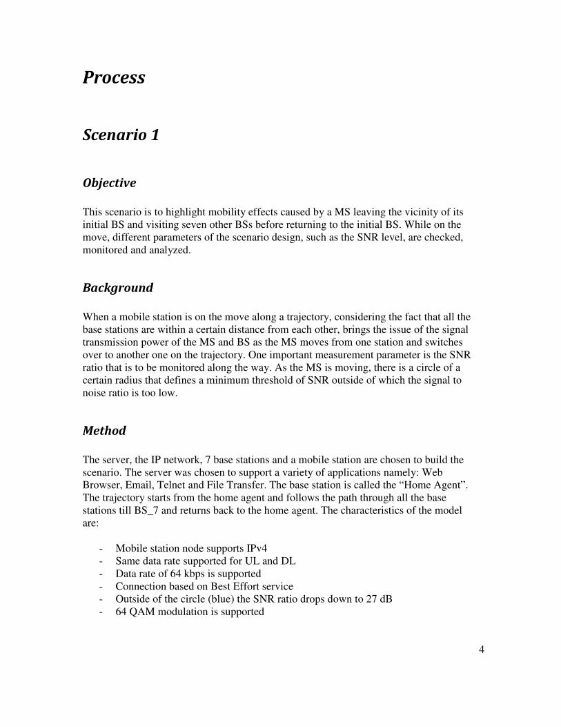
The server, the IP network, 7 base stations and a mobile station are chosen to build the
scenario. The server was chosen to support a variety of applications namely: Web
Browser, Email, Telnet and File Transfer. The base station is called the “Home Agent”.
The trajectory starts from the home agent and follows the path through all the base
stations till BS_7 and returns back to the home agent. The characteristics of the model
are:
- Mobile station node supports IPv4
- Same data rate supported for UL and DL
- Data rate of 64 kbps is supported
- Connection based on Best Effort service
- Outside of the circle (blue) the SNR ratio drops down to 27 dB
- 64 QAM modulation is supported
4
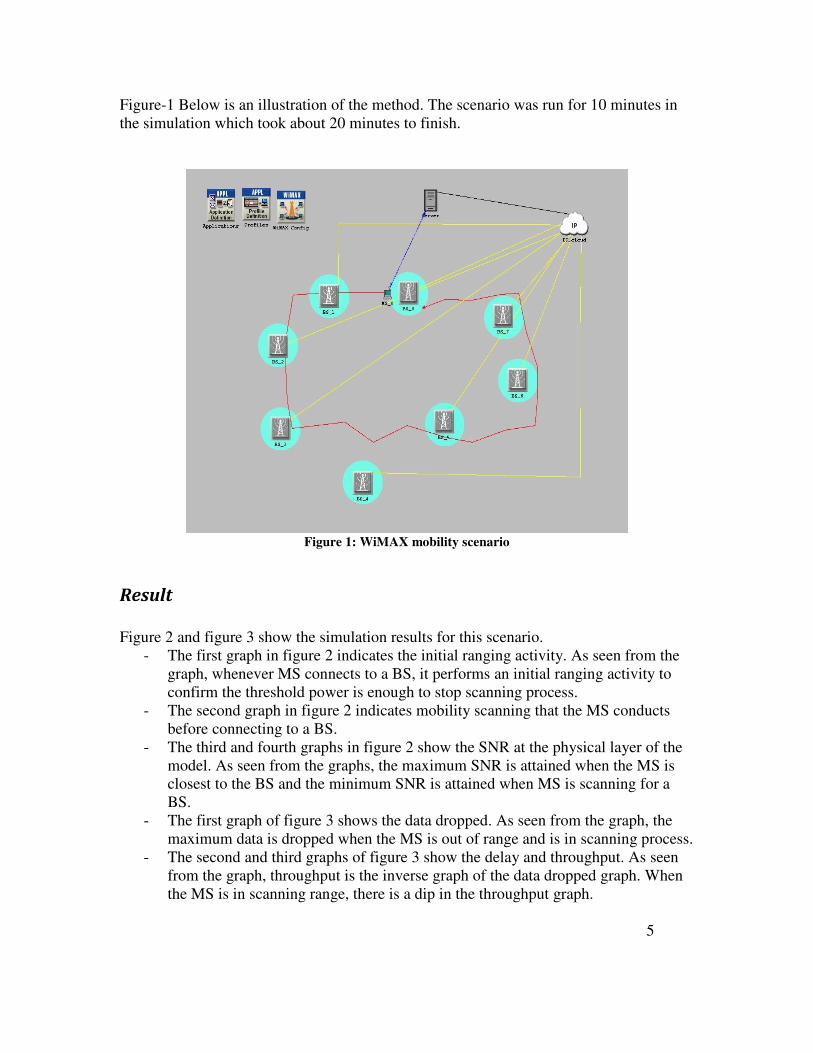
Figure-1 Below is an illustration of the method. The scenario was run for 10 minutes in
the simulation which took about 20 minutes to finish.
Figure 1: WiMAX mobility scenario
Result
Figure 2 and figure 3 show the simulation results for this scenario.
- The first graph in figure 2 indicates the initial ranging activity. As seen from the
graph, whenever MS connects to a BS, it performs an initial ranging activity to
confirm the threshold power is enough to stop scanning process.
- The second graph in figure 2 indicates mobility scanning that the MS conducts
before connecting to a BS.
- The third and fourth graphs in figure 2 show the SNR at the physical layer of the
model. As seen from the graphs, the maximum SNR is attained when the MS is
closest to the BS and the minimum SNR is attained when MS is scanning for a
BS.
- The first graph of figure 3 shows the data dropped. As seen from the graph, the
maximum data is dropped when the MS is out of range and is in scanning process.
- The second and third graphs of figure 3 show the delay and throughput. As seen
from the graph, throughput is the inverse graph of the data dropped graph. When
the MS is in scanning range, there is a dip in the throughput graph.
5
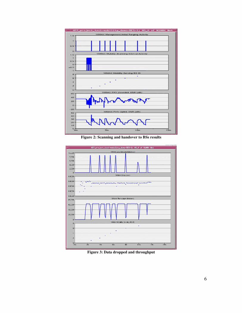
Figure 2: Scanning and handover to BSs results
Figure 3: Data dropped and throughput
6
Scenario 2
Objective
This scenario focuses on the scanning procedure that a WiMAX mobile station does
when looking for more suitable base stations in its vicinity. We modify three parameters
and analyze the effects. These parameters are scan duration, interleaving interval, and
number of iterations. We differentiate between light scanning and dense scanning. We
intend to show that light scanning allows for more data throughput from server to client,
while dense scanning has a lower throughput but less handover delay.
Background
While a WiMAX mobile station is moving, it constantly scans for neighboring base
stations and transfers data between itself and the base station that it is currently connected
with. The purpose of these scans is to determine if it could acquire a connection with a
more suitable base station. This could be because of a better wireless signal SNR, a base
station with lower traffic, etc.
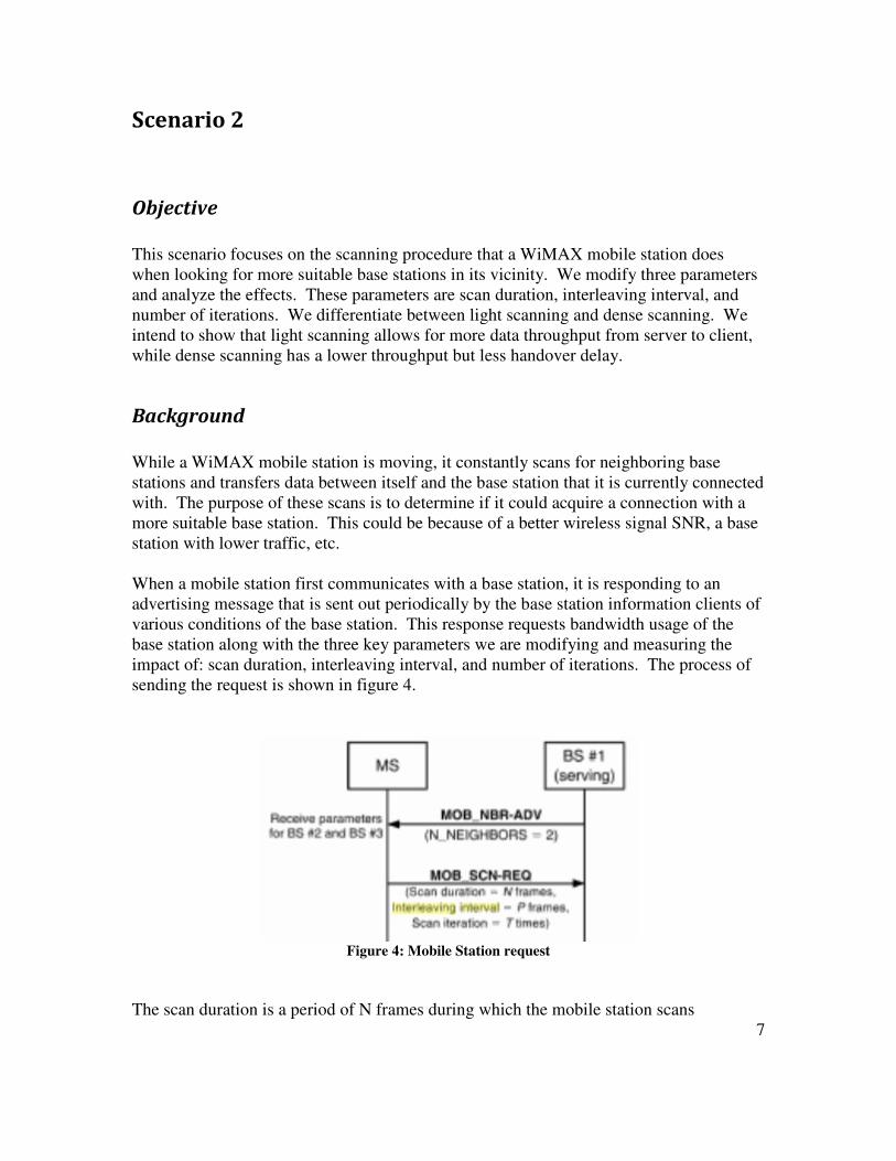
When a mobile station first communicates with a base station, it is responding to an
advertising message that is sent out periodically by the base station information clients of
various conditions of the base station. This response requests bandwidth usage of the
base station along with the three key parameters we are modifying and measuring the
impact of: scan duration, interleaving interval, and number of iterations. The process of
sending the request is shown in figure 4.
Figure 4: Mobile Station request
The scan duration is a period of N frames during which the mobile station scans
7
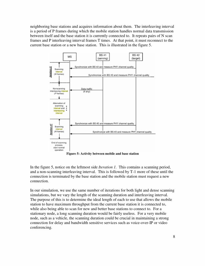
neighboring base stations and acquires information about them. The interleaving interval
is a period of P frames during which the mobile station handles normal data transmission
between itself and the base station it is currently connected to. It repeats pairs of N scan
frames and P interleaving interval frames T times. At that point, it must reconnect to the
current base station or a new base station. This is illustrated in the figure 5.
Figure 5: Activity between mobile and base station
In the figure 5, notice on the leftmost side Iteration 1. This contains a scanning period,
and a non-scanning interleaving interval. This is followed by T-1 more of these until the
connection is terminated by the base station and the mobile station must request a new
connection.
In our simulation, we use the same number of iterations for both light and dense scanning
simulations, but we vary the length of the scanning duration and interleaving interval.
The purpose of this is to determine the ideal length of each to use that allows the mobile
station to have maximum throughput from the current base station it is connected to,
while also being able to scan for new and better base stations to connect to. For a
stationary node, a long scanning duration would be fairly useless. For a very mobile
node, such as a vehicle, the scanning duration could be crucial in maintaining a strong
connection for delay and bandwidth sensitive services such as voice-over-IP or video
conferencing.
8
Method
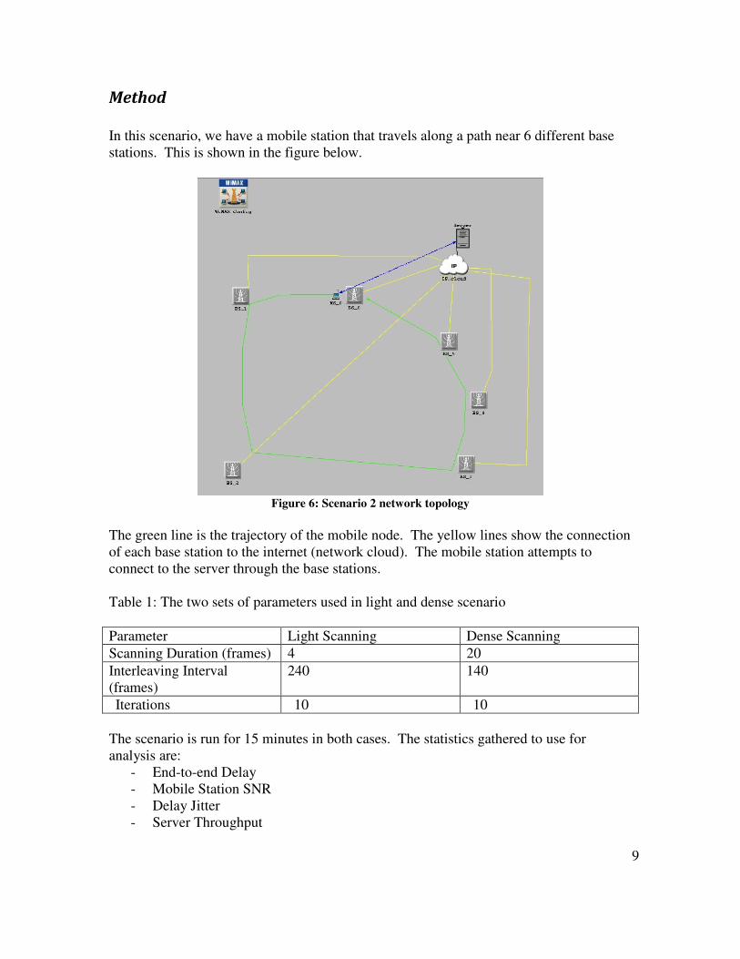
In this scenario, we have a mobile station that travels along a path near 6 different base
stations. This is shown in the figure below.
Figure 6: Scenario 2 network topology
The green line is the trajectory of the mobile node. The yellow lines show the connection
of each base station to the internet (network cloud). The mobile station attempts to
connect to the server through the base stations.
Table 1: The two sets of parameters used in light and dense scenario
Parameter Light Scanning Dense Scanning
Scanning Duration (frames) 4 20
Interleaving Interval
(frames)
240 140
Iterations 10 10
The scenario is run for 15 minutes in both cases. The statistics gathered to use for
analysis are:
- End-to-end Delay
- Mobile Station SNR
- Delay Jitter
- Server Throughput
9
Results
We obtained the following results
Table 2: Comparison between light and dense scanning results
Statistic Value (light scanning) Value (dense scanning)
End-to-end Delay 48 ms 60 ms
Delay Jitter 22 ms 33 ms
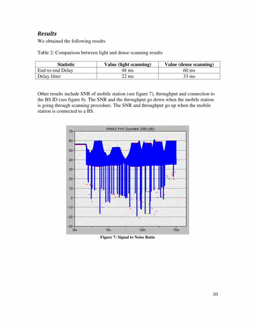
Other results include SNR of mobile station (see figure 7), throughput and connection to
the BS ID (see figure 8). The SNR and the throughput go down when the mobile station
is going through scanning procedure. The SNR and throughput go up when the mobile
station is connected to a BS.
Figure 7: Signal to Noise Ratio
10
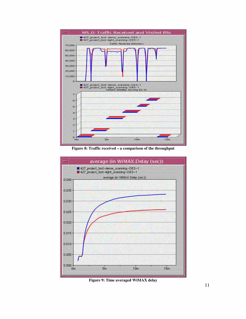
Figure 8: Traffic received – a comparison of the throughput
Figure 9: Time averaged WiMAX delay
11
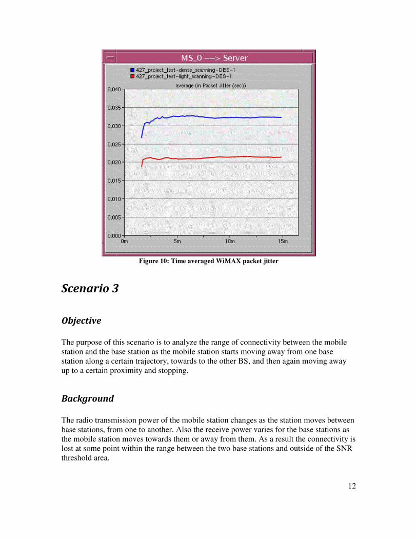
Figure 10: Time averaged WiMAX packet jitter
Scenario 3
Objective
The purpose of this scenario is to analyze the range of connectivity between the mobile
station and the base station as the mobile station starts moving away from one base
station along a certain trajectory, towards to the other BS, and then again moving away
up to a certain proximity and stopping.
Background
The radio transmission power of the mobile station changes as the station moves between
base stations, from one to another. Also the receive power varies for the base stations as
the mobile station moves towards them or away from them. As a result the connectivity is
lost at some point within the range between the two base stations and outside of the SNR
threshold area.
12
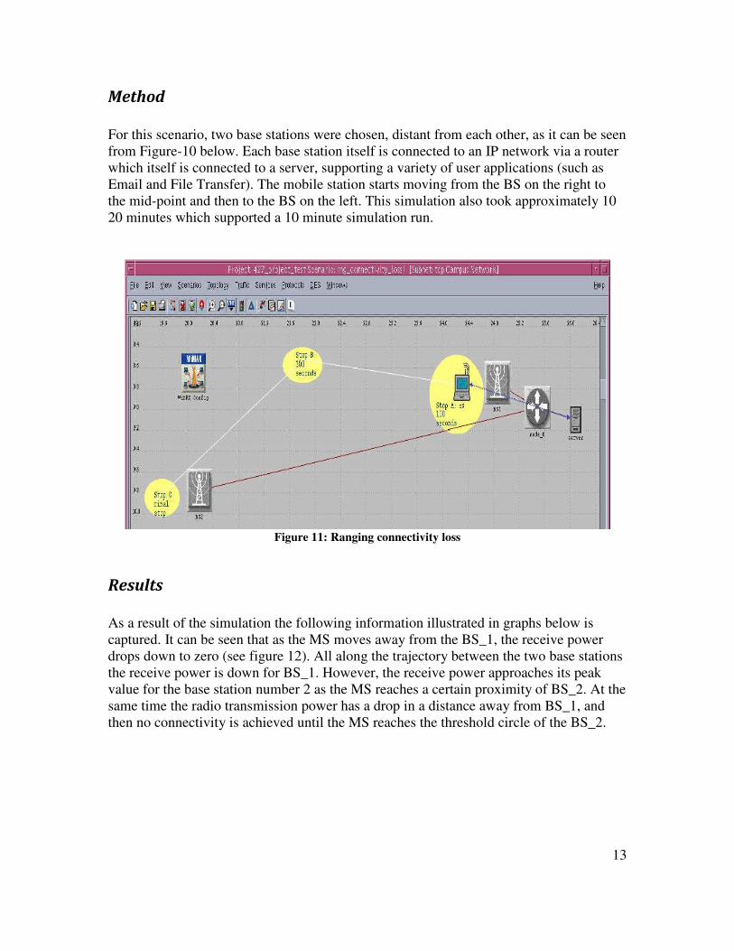
Method
For this scenario, two base stations were chosen, distant from each other, as it can be seen
from Figure-10 below. Each base station itself is connected to an IP network via a router
which itself is connected to a server, supporting a variety of user applications (such as
Email and File Transfer). The mobile station starts moving from the BS on the right to
the mid-point and then to the BS on the left. This simulation also took approximately 10
20 minutes which supported a 10 minute simulation run.
Figure 11: Ranging connectivity loss
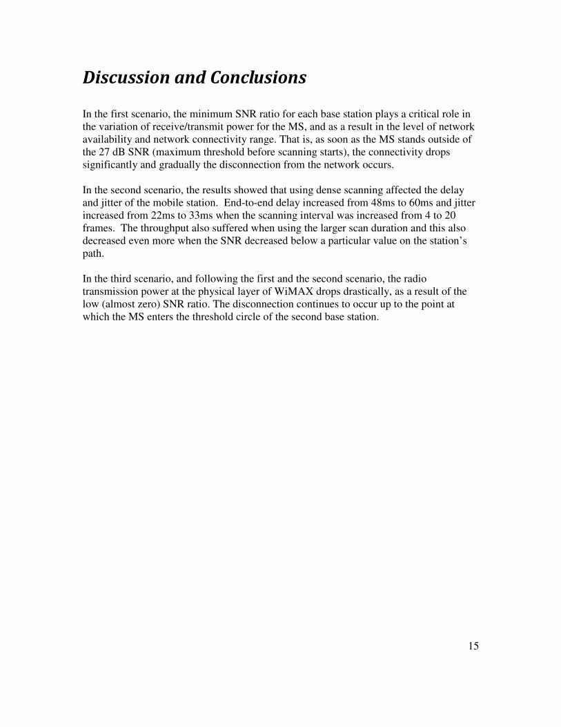
Results
As a result of the simulation the following information illustrated in graphs below is
captured. It can be seen that as the MS moves away from the BS_1, the receive power
drops down to zero (see figure 12). All along the trajectory between the two base stations
the receive power is down for BS_1. However, the receive power approaches its peak
value for the base station number 2 as the MS reaches a certain proximity of BS_2. At the
same time the radio transmission power has a drop in a distance away from BS_1, and
then no connectivity is achieved until the MS reaches the threshold circle of the BS_2.
13
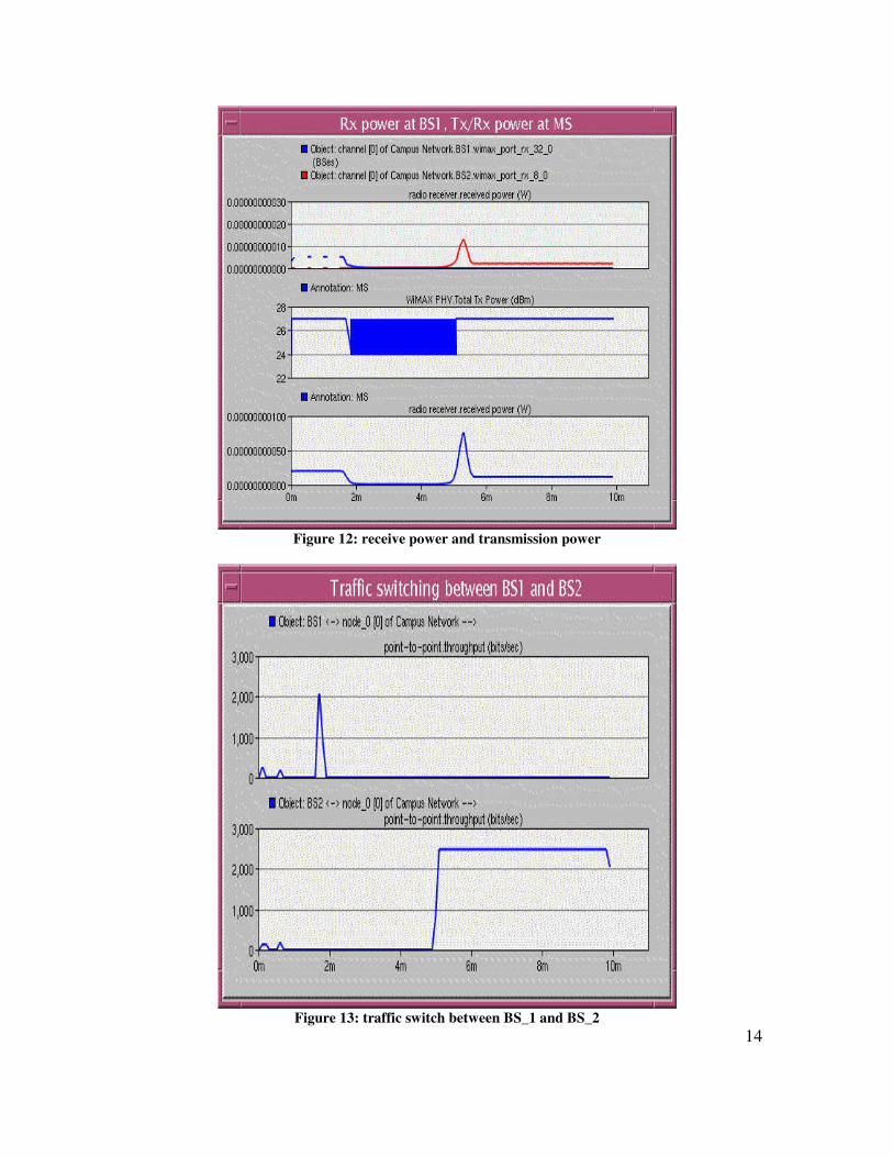
Figure 12: receive power and transmission power
Figure 13: traffic switch between BS_1 and BS_2
14
Discussion and Conclusions
In the first scenario, the minimum SNR ratio for each base station plays a critical role in
the variation of receive/transmit power for the MS, and as a result in the level of network
availability and network connectivity range. That is, as soon as the MS stands outside of
the 27 dB SNR (maximum threshold before scanning starts), the connectivity drops
significantly and gradually the disconnection from the network occurs.
In the second scenario, the results showed that using dense scanning affected the delay
and jitter of the mobile station. End-to-end delay increased from 48ms to 60ms and jitter
increased from 22ms to 33ms when the scanning interval was increased from 4 to 20
frames. The throughput also suffered when using the larger scan duration and this also
decreased even more when the SNR decreased below a particular value on the station’s
path.
In the third scenario, and following the first and the second scenario, the radio
transmission power at the physical layer of WiMAX drops drastically, as a result of the
low (almost zero) SNR ratio. The disconnection continues to occur up to the point at
which the MS enters the threshold circle of the second base station.
15
Citations and References
[1]. W. Hrudey, "Streaming Video Content Over IEEE 802.16 / WiMAX Broadband
Access" Communication Networks, Final Project, spring. 2007. Available at:
http://www.sfu.ca/~whrudey/report.pdf
[2]. "WiMAX™ System Evaluation Methodology" V2.1 WiMAX Forum, July, 2008.
Available at:
http://www.wimaxforum.org/sites/wimaxforum.org/files/documentation/2009/wimax_sys
tem_evaluation_methodology_v2_1.pdf
[3]. D. Johnston, H. Yaghoobi, "Peering Into the WiMAX Spec: Part 1" Intel Corp.,
January. 2004. Available at:
http://www.commsdesign.com/showArticle.jhtml;jsessionid=1GYUGOALI50V0QSNDL
RCKH0CJUNN2JVN?articleID=17500156
[4]. M. Brain, E. Grabianowski, "How WiMAX Works" Online Article. Available at:
http://www.howstuffworks.com/wimax1.htm
[5]. M. Brain, E. Grabianowski, "802.16
TM IEEE Standard for Local and metropolitan
area networks" IEEE Std 802.16TM
-2004. Available at:
http://standards.ieee.org/getieee802/download/802.16-2004.pdf
[6]. S. Ahson, Mohammad I, WiMAX: Standards and Security. Published by CRC Press,
2007
[7]. M. C. Lax, A. Dammander, WiMAX - A Study of Mobility and a MAC-layer
Implementation in GloMoSim, Ume°a University Department of Computing Science,
April 2006, Available at:
http://www.cs.umu.se/education/examina/Rapporter/CarlbergDammander.pdf
[8]. T. He, B. Blum, Y. Pointurier, C. Lu, J. A. Stankovic, S. Son, MAC Layer
Abstraction for Simulation Scalability 1 Improvements in Large-scale Sensor Networks,
Department of Computer Science, University of Virginia, Department of Computer
Science and Engineering, University of Minnesota, Department of Computer Science and
Engineering, Washington University in St. Louis, Available at:
http://www.cs.virginia.edu/papers/MACAbstraction.pdf
[9]. Y. S. Chen, K. Chou, I. Fu, P. Cheng, Scanning Procedure with Cell Prioritization for
IEEE 802.16m, IEEE, July 2008.
[10]. Design WiMAX (802.16) Network and Devices, Available at:
http://www.opnet.com/training/network_rd/modeler.html
16
[11]. Introduction to WiMAX Modeling for Network R&D and Planning, Available at:
http://www.opnet.com/training/network_rd/modeler.html
[12]. Understanding WiMAX Model Internals and Interfaces, Available at:
http://www.opnet.com/training/network_rd/modeler.html
17