Embed Size (px)
Citation preview
Enterprise AWS Quick Start Guide
v8.0.1
rev. 1.1.9
Copyright © 2002 – 2016 Loadbalancer.org, Inc
Table of ContentsIntroduction.....................................................................................................................................................................4About Enterprise AWS..................................................................................................................................................4
Main Differences to the Non-Cloud Product..................................................................................................................4Why use Enterprise AWS?...................................................................................................................................................... 5
Amazon Terminology...................................................................................................................................................5Getting Started...............................................................................................................................................................5Deployment Concepts................................................................................................................................................6
Overview..................................................................................................................................................................................... 6VPC Wizard Setup.................................................................................................................................................................... 6VPC IP Address Types.............................................................................................................................................................. 7VPC Network Interfaces (ENI)............................................................................................................................................... 7Instance Type............................................................................................................................................................................. 7
Deploying Enterprise AWS..........................................................................................................................................8STEP A - Create a VPC....................................................................................................................................................... 8STEP B – Accessing & Deploying the AMI................................................................................................................ 10
Checking your Subscriptions............................................................................................................................................. 14Accessing the Appliance...........................................................................................................................................14
Accessing the Appliance using the WUI.........................................................................................................................14WUI Menu Options................................................................................................................................................................ 15Accessing the Appliance using SSH.................................................................................................................................18
Using Linux......................................................................................................................................................................... 18Using Windows.................................................................................................................................................................. 18
Accessing the Appliance using SCP................................................................................................................................. 21Using Linux.......................................................................................................................................................................... 21Using Windows.................................................................................................................................................................. 21
Configuration Examples...........................................................................................................................................221) Load balancing Web Servers – 1 Subnet, 1 Interface, Layer 7.............................................................................22
a) Setting up AWS....................................................................................................................................................... 22b) Setting up the Virtual Service............................................................................................................................ 22c) Setting up the Real Servers................................................................................................................................. 23d) Applying the new Layer 7 Settings................................................................................................................... 23e) Associating the VIP with an Elastic IP Address (If access from the Internet is required).................23
2) Load balancing Web Servers - 1 Subnet, 1 Interface, Layer 4.............................................................................25a) Setting up AWS....................................................................................................................................................... 25b) Setting up the Virtual Service............................................................................................................................ 25c) Setting up the Real Servers................................................................................................................................. 26d) Associating the VIP with an Elastic IP Address (If access from the Internet is required)................26e) Enable Internet Connectivity via the Load Balancer for the Real Servers (If Required)...................27
3) Load balancing Web Servers – 2 Subnets, 2 Interfaces, Layer 7........................................................................28a) Setting up AWS....................................................................................................................................................... 28b) Configuring the second Network Interface..................................................................................................28c) Setting up the Virtual Service............................................................................................................................ 28d) Setting up the Real Servers................................................................................................................................ 29e) Applying the new Layer 7 Settings................................................................................................................... 29f) Associating the VIP with an Elastic IP Address (If access from the Internet is required).................30
4) Load balancing Web Servers - 2 Subnets, 1 Interface, Layer 7 with Transparency.......................................31a) Setting up AWS....................................................................................................................................................... 31b) Setting up the Virtual Service............................................................................................................................. 31c) Setting up the Real Servers................................................................................................................................. 32d) Configuring Layer 7 – Advanced Settings.....................................................................................................33e) Applying the new Layer 7 Settings................................................................................................................... 33f) Associating the VIP with an Elastic IP Address (If access from the Internet is required)..................33
5) Load balancing Web Servers - 1 Subnet, 1 Interface, Layer 7 with SSL Termination...................................34
a) Setting up AWS....................................................................................................................................................... 34b) Setting up the Virtual Service............................................................................................................................ 34c) Setting up the Real Servers................................................................................................................................. 34d) Configuring SSL Termination............................................................................................................................. 35e) Applying the new Settings.................................................................................................................................. 36f) Associating the VIP with an Elastic IP Address (If access from the Internet is required).................36
6) Load balancing RD Session Hosts - 2 Subnets, 1 Interface, Layer 7.................................................................38a) Setting up AWS....................................................................................................................................................... 38b) Setting up the Virtual Service............................................................................................................................ 38c) Setting up the Real Servers................................................................................................................................. 39d) Applying the new Layer 7 Settings..................................................................................................................40e) Associating the VIP with an Elastic IP Address (If access from the Internet is required)...............40
7) Load balancing Web Servers - 2 Subnets, 1 Interface, Layer 4...........................................................................41a) Setting up AWS....................................................................................................................................................... 41b) Setting up the Virtual Service............................................................................................................................. 41c) Setting up the Real Servers................................................................................................................................. 42d) Associating the VIP with an Elastic IP Address (If access from the Internet is required)................42e) Enable Internet Connectivity via the Load Balancer for the Real Servers (If Required)..................43
Testing & Validation...................................................................................................................................................44Testing Load Balanced Services....................................................................................................................................... 44
Diagnosing VIP Connection Problems...................................................................................................................... 44Taking Real Servers Offline............................................................................................................................................ 45Using Reports & Log Files.............................................................................................................................................. 46
Configuring High Availability using two Instances (Master & Slave)..........................................................47Loadbalancer.org Technical Support...................................................................................................................50Appendix.........................................................................................................................................................................51
1 - IAM Role Configuration.................................................................................................................................................. 512 - Configuring the load balancer to auto add/remove auto-scaled Real Servers..........................................523 - Configuring Auto-Scaling to auto deploy a new LB.org Instance on Failure..............................................534 - Company Contact Information.................................................................................................................................. 58
IntroductionAmazon Web Services (AWS) provides a cloud based platform to deploy web services. It allows services to be deployed as and when required. Charges are made for what is used making it an extremely flexible and cost effective solution.
Enterprise AWS allows customers to rapidly deploy and configure a load balancing solution within the Amazon cloud. The latest Loadbalancer.org AWS appliance enables both Layer 4 and layer 7 virtual services to be quickly and easily configured.
About Enterprise AWSThe core software is based on customized versions of Centos 6 / RHEL 6, Linux 3.10, LVS, HA-Linux, HAProxy, Pound, STunnel & Ldirectord.
Enterprise AWS can be deployed as a single instance or as an HA clustered pair of instances for high availability and resilience. For details of adding a second (slave) instance, please refer to page 47.
Enterprise AWS is based on our main hardware/virtual product and has almost identical features. There are certain differences due to the way the Amazon EC2 environment works, these are listed below.
Main Differences to the Non-Cloud Product
• The network setup is customized for Amazon EC2 deployment
• Layer 4 Direct Routing (DR) mode is not supported
• Dual interface layer 4 NAT mode where each interface of the load balancer is connected to a different subnet and the default gateway of the real servers is configured to be the load balancer is not supported
Single interface mode should be used instead, and a default route with the target set as the load balancer instance should be added to the routing table of the subnet where the real servers are located – please refer to page 31 for an example
Also, for a clustered pair of load balancers (master & slave) the AWS routing table for the Real Server subnet must be dynamically changed when failover from the active to passive device occurs. This can be achieved using the WUI option: Cluster Configuration > Heartbeat Advanced, and the AWS command ec2-replace-route as detailed on page 48
• Dual interface layer 7 SNAT mode with TProxy where each interface of the load balancer is connected to a different subnet and the default gateway of the real servers is configured to be the load balancer is not supported
Single interface mode should be used instead, and a default route with the target set as the load balancer instance should be added to the routing table of the subnet where the real servers are located – please refer to page 41 for an example
Also, for a clustered pair of load balancers (master & slave) the AWS routing table for the Real Server subnet must be dynamically changed when failover from the active to passive device occurs. This can be achieved using the WUI option: Cluster Configuration > Heartbeat Advanced, and the AWS command ec2-replace-route as detailed on page 48
• The WUI is not accessible on HTTP port 9080, only HTTPS port 9443
4
Why use Enterprise AWS?
Amazon enables users to setup Elastic Load Balancing for load balancing other EC2 instances running in the cloud. This does provide basic load balancing functionality but is limited in several areas. Loadbalancer.org's Enterprise AWS load balancer provides the following additional features & advantages:
1. Load balances virtually any TCP or UDP based protocol
2. Ability to deploy a clustered pair of instances for High Availability: one active, one passive
3. Load balances both EC2 based and non-EC2 based servers
4. Supports customizable timeouts for custom applications beyond those offered by AWS
5. Supports comprehensive back-end server health-check options
6. Enables fallback servers to be configured and invoked when all load balanced servers/services fail
7. Provides extensive real time and historical statistics reports
8. Supports session distribution based on actual server load (utilizing Loadbalancer.org's feedback agent which is available for both Linux & Windows)
9. Supports source IP based persistence
10. Supports RDP Cookie based persistence
11. Supports full integration with Remote Desktop Services Connection Broker
12. Supports multiple load balanced services running on multiple IP addresses
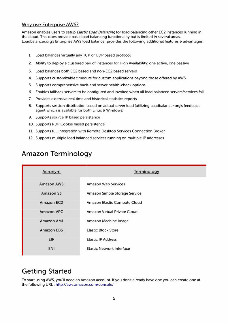
Amazon Terminology
Acronym Terminology
Amazon AWS Amazon Web Services
Amazon S3 Amazon Simple Storage Service
Amazon EC2 Amazon Elastic Compute Cloud
Amazon VPC Amazon Virtual Private Cloud
Amazon AMI Amazon Machine Image
Amazon EBS Elastic Block Store
EIP Elastic IP Address
ENI Elastic Network Interface
Getting StartedTo start using AWS, you'll need an Amazon account. If you don't already have one you can create one at the following URL : http://aws.amazon.com/console/
5
Deployment Concepts
Overview
Instances must be deployed within a VPC (Virtual Private Cloud). This is because the appliance requires a minimum of 2 private IP addresses – one for the interface and one for the load balanced VIP. EC2 classic only supports a single private IP address and a corresponding EIP mapped via NAT.
The easiest way to configure a VPC is to use the wizard available in the AWS / VPC console.
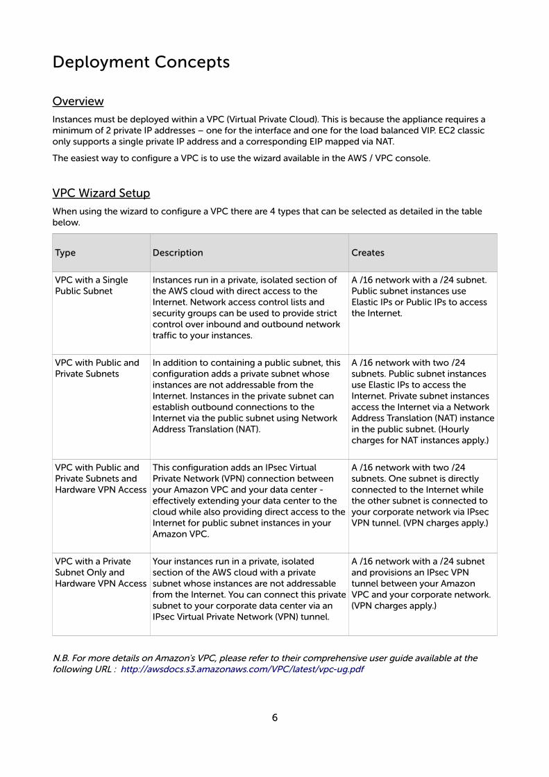
VPC Wizard Setup
When using the wizard to configure a VPC there are 4 types that can be selected as detailed in the table below.
Type Description Creates
VPC with a Single Public Subnet
Instances run in a private, isolated section of the AWS cloud with direct access to the Internet. Network access control lists and security groups can be used to provide strict control over inbound and outbound network traffic to your instances.
A /16 network with a /24 subnet. Public subnet instances use Elastic IPs or Public IPs to access the Internet.
VPC with Public and Private Subnets
In addition to containing a public subnet, this configuration adds a private subnet whose instances are not addressable from the Internet. Instances in the private subnet can establish outbound connections to the Internet via the public subnet using Network Address Translation (NAT).
A /16 network with two /24 subnets. Public subnet instances use Elastic IPs to access the Internet. Private subnet instances access the Internet via a Network Address Translation (NAT) instancein the public subnet. (Hourly charges for NAT instances apply.)
VPC with Public and Private Subnets and Hardware VPN Access
This configuration adds an IPsec Virtual Private Network (VPN) connection between your Amazon VPC and your data center - effectively extending your data center to the cloud while also providing direct access to theInternet for public subnet instances in your Amazon VPC.
A /16 network with two /24 subnets. One subnet is directly connected to the Internet while the other subnet is connected to your corporate network via IPsec VPN tunnel. (VPN charges apply.)
VPC with a Private Subnet Only and Hardware VPN Access
Your instances run in a private, isolated section of the AWS cloud with a private subnet whose instances are not addressable from the Internet. You can connect this privatesubnet to your corporate data center via an IPsec Virtual Private Network (VPN) tunnel.
A /16 network with a /24 subnet and provisions an IPsec VPN tunnel between your Amazon VPC and your corporate network. (VPN charges apply.)
N.B. For more details on Amazon's VPC, please refer to their comprehensive user guide available at the following URL : http://awsdocs.s3.amazonaws.com/VPC/latest/vpc-ug.pdf
6
VPC IP Address Types
There are 3 IP address types as detailed below:
Private
The internal RFC 1918 address of an instance that is only routable within the EC2 Cloud. Network traffic originating outside the EC2 network cannot route to this IP, and must use the Public IP or Elastic IP Address mapped to the instance.
Public
Internet routable IP address assigned by the system for all instances. Traffic routed to the Public IP is translated via 1:1 Network Address Translation (NAT) and forwarded to the Private IP address of an instance.The mapping of a Public IP to Private IP of an instance is the default launch configuration for all instance types. Public IP Addresses are no longer usable upon instance termination.
Elastic (EIP)
Internet routable IP address allocated to an AWS EC2 account. Similar to EC2 Public Address, 1:1 NAT is used to map Elastic IP Addresses with their associated Private IP addresses. Unlike a standard EC2 Public IP Address, Elastic IP Addresses are allocated to accounts and can be remapped to other instances when desired.
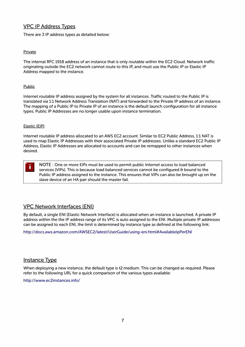
NOTE : One or more EIPs must be used to permit public Internet access to load balanced services (VIPs). This is because load balanced services cannot be configured & bound to the Public IP address assigned to the instance. This ensures that VIPs can also be brought up on the slave device of an HA pair should the master fail.
VPC Network Interfaces (ENI)
By default, a single ENI (Elastic Network Interface) is allocated when an instance is launched. A private IP address within the the IP address range of its VPC is auto assigned to the ENI. Multiple private IP addresses can be assigned to each ENI, the limit is determined by instance type as defined at the following link:
http://docs.aws.amazon.com/AWSEC2/latest/UserGuide/using-eni.html#AvailableIpPerENI
Instance Type
When deploying a new instance, the default type is t2.medium. This can be changed as required. Please refer to the following URL for a quick comparison of the various types available:
http://www.ec2instances.info/
7
Deploying Enterprise AWS
STEP A - Create a VPC
For a manually created VPC, the key steps are:
1. Create a VPC - this is an isolated portion of the AWS cloud
2. Create and attach an Internet gateway - this connects the VPC directly to the Internet and providesaccess to other AWS products
3. Create an Amazon VPC subnet - this is a segment of a VPC's IP address range that you can launch Amazon EC2 instances into
4. Set up routing in the VPC - this enables traffic to flow between the subnet and the Internet
5. Set Up a Security Group for the VPC - this controls the inbound and outbound traffic
However, as mentioned previously the easiest way to configure a VPC is by using the VPC Wizard. The wizard covers steps 1-4.
To create a VPC using the wizard:
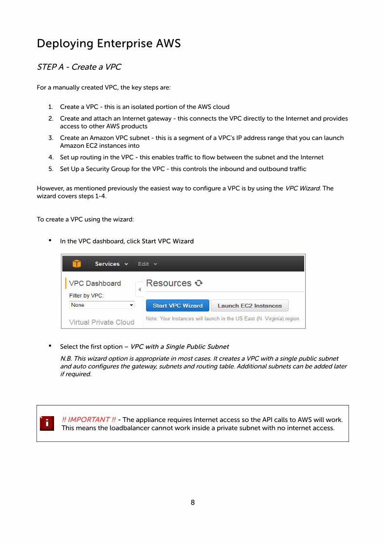
• In the VPC dashboard, click Start VPC Wizard
• Select the first option – VPC with a Single Public Subnet
N.B. This wizard option is appropriate in most cases. It creates a VPC with a single public subnet and auto configures the gateway, subnets and routing table. Additional subnets can be added laterif required.
!! IMPORTANT !! - The appliance requires Internet access so the API calls to AWS will work. This means the loadbalancer cannot work inside a private subnet with no internet access.
8
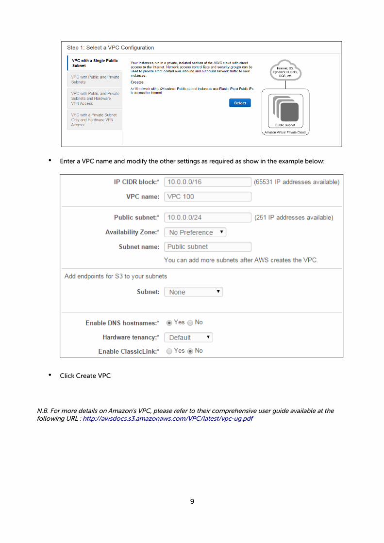
• Enter a VPC name and modify the other settings as required as show in the example below:
• Click Create VPC
N.B. For more details on Amazon's VPC, please refer to their comprehensive user guide available at the following URL : http://awsdocs.s3.amazonaws.com/VPC/latest/vpc-ug.pdf
9

STEP B – Accessing & Deploying the AMI
!! IMPORTANT !! - Make sure you configure an IAM role, the instance will not work correctly if this is not done. Please refer to page 11 and section 1 in the Appendix.
To access and deploy the AMI:
• In the EC2 Dashboard, click Launch Instance
• Select AWS Marketplace
• Search for “Loadbalancer.org”
• Click Select next to the required instance
• Select the required pricing options (hourly or annual)
• Click the Launch with EC2 Console button next to the required Region
• Select the required instance type – t2.medium is recommended, but depends on your requirements
10

• Click Next: Configure Instance Details
• Change Network to the required VPC
• If the VPC was created with the wizard, the public subnet's auto-assign Public IP option will be disabled. To automatically allocate a public IP address, change Auto-assign Public IP to “Enable”
• Select a suitable IAM Role. The role can simply have “Amazon EC2 Full Access” for the “Amazon EC2” AWS Service Role or for more granular configuration, please refer to section 1 in the Appendix.
!! IMPORTANT !! - Make sure you configure an IAM role, the instance will not work correctly if this is not done.
Network Interfaces - typically there is no need to add additional interfaces. Load balancing real servers in different subnets is configured by changing AWS routing rules. The routing rules required depend on where the real servers and located (same or different subnet as the load balancer) and the load balancing mode. Please refer to the deployment examples starting on page 22 for more details.
• Click Next: Add Storage
11
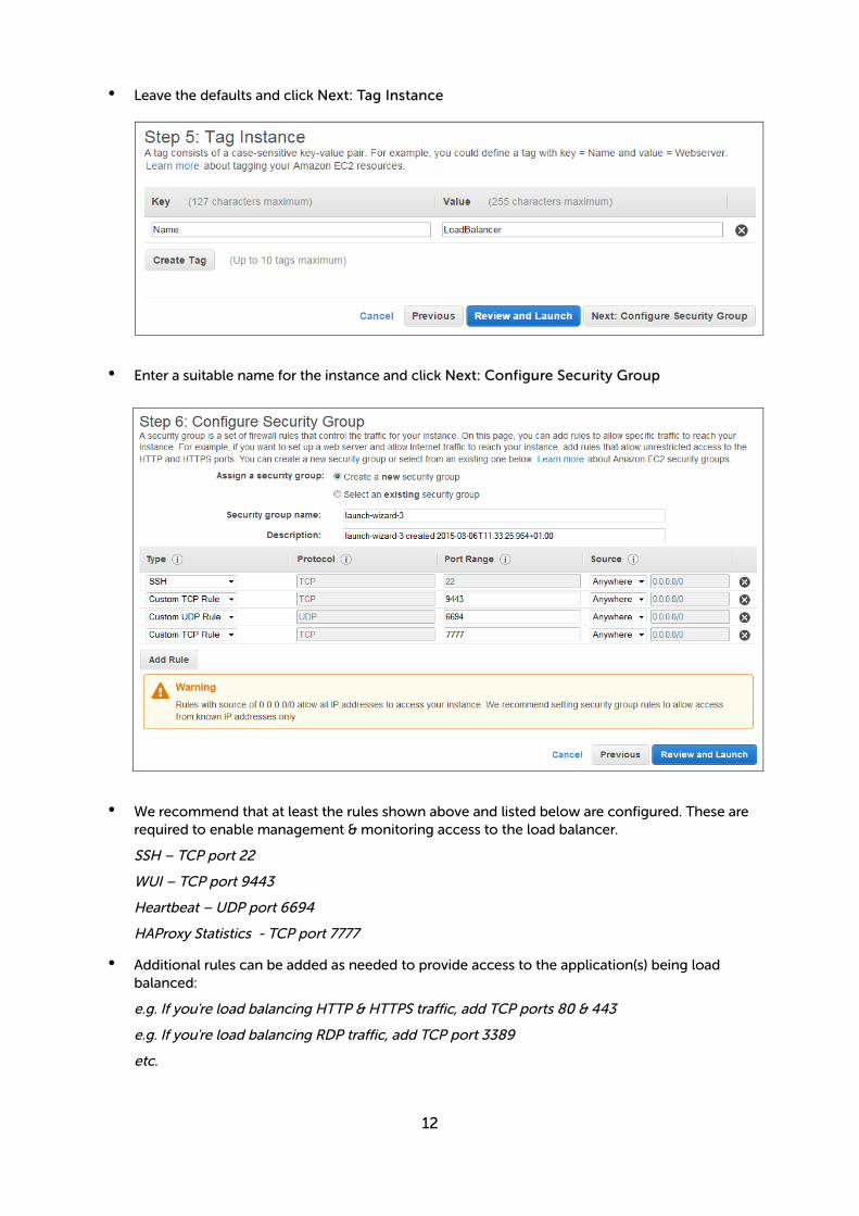
• Leave the defaults and click Next: Tag Instance
• Enter a suitable name for the instance and click Next: Configure Security Group
• We recommend that at least the rules shown above and listed below are configured. These are required to enable management & monitoring access to the load balancer.
SSH – TCP port 22
WUI – TCP port 9443
Heartbeat – UDP port 6694
HAProxy Statistics - TCP port 7777
• Additional rules can be added as needed to provide access to the application(s) being load balanced:
e.g. If you're load balancing HTTP & HTTPS traffic, add TCP ports 80 & 443
e.g. If you're load balancing RDP traffic, add TCP port 3389
etc.
12
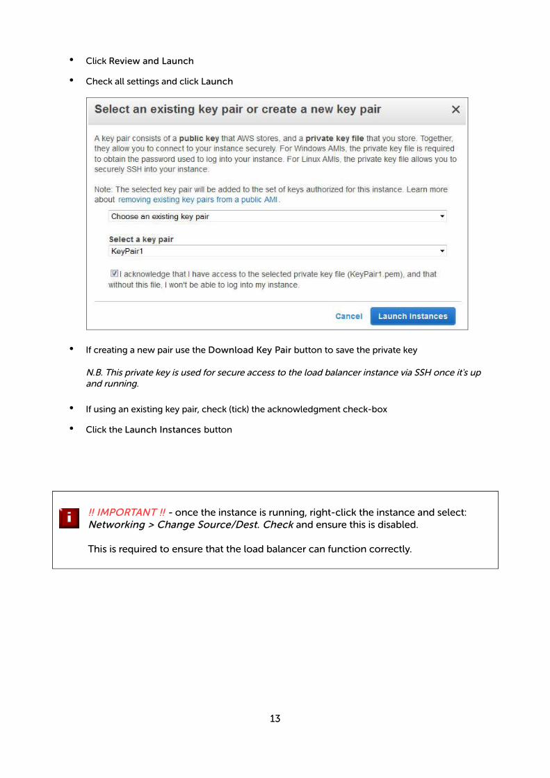
• Click Review and Launch
• Check all settings and click Launch
• If creating a new pair use the Download Key Pair button to save the private key
N.B. This private key is used for secure access to the load balancer instance via SSH once it's up and running.
• If using an existing key pair, check (tick) the acknowledgment check-box
• Click the Launch Instances button
!! IMPORTANT !! - once the instance is running, right-click the instance and select: Networking > Change Source/Dest. Check and ensure this is disabled.
This is required to ensure that the load balancer can function correctly.
13
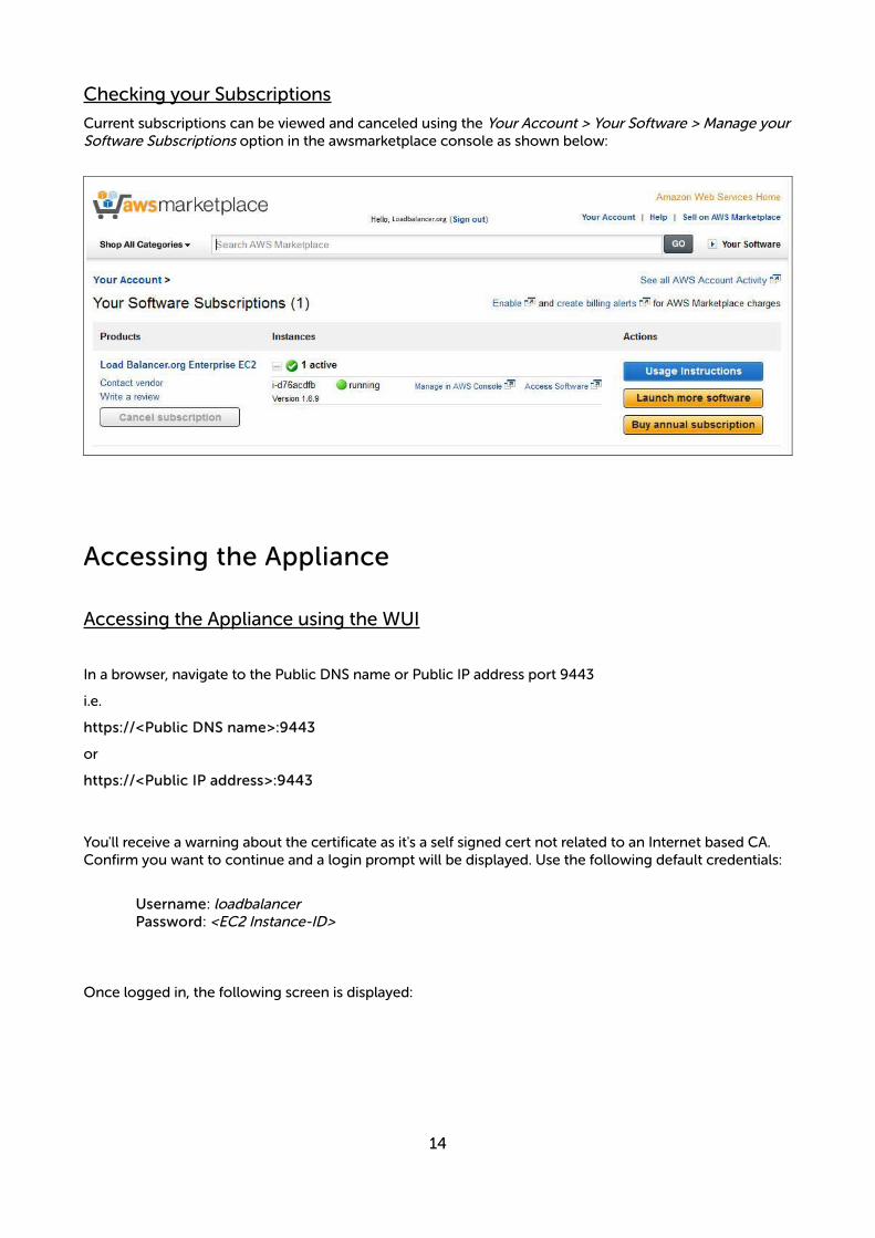
Checking your Subscriptions
Current subscriptions can be viewed and canceled using the Your Account > Your Software > Manage yourSoftware Subscriptions option in the awsmarketplace console as shown below:
Accessing the Appliance
Accessing the Appliance using the WUI
In a browser, navigate to the Public DNS name or Public IP address port 9443
i.e.
https://<Public DNS name>:9443
or
https://<Public IP address>:9443
You'll receive a warning about the certificate as it's a self signed cert not related to an Internet based CA. Confirm you want to continue and a login prompt will be displayed. Use the following default credentials:
Username: loadbalancerPassword: <EC2 Instance-ID>
Once logged in, the following screen is displayed:
14
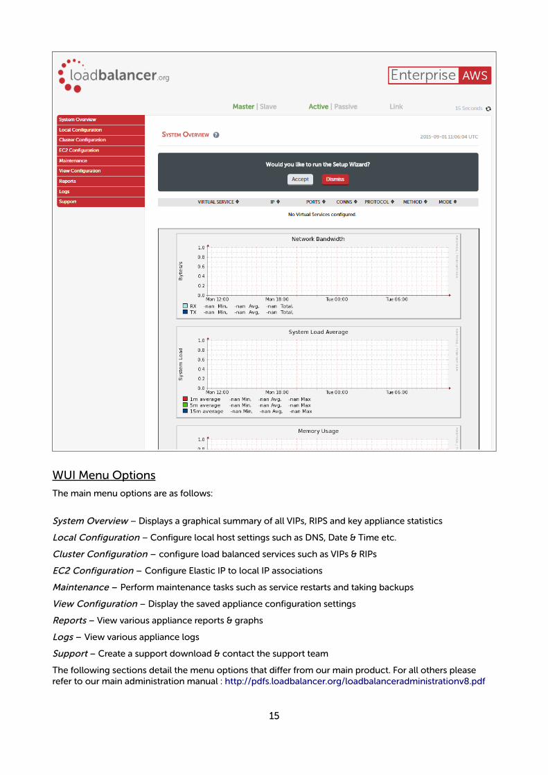
WUI Menu Options
The main menu options are as follows:
System Overview – Displays a graphical summary of all VIPs, RIPS and key appliance statistics
Local Configuration – Configure local host settings such as DNS, Date & Time etc.
Cluster Configuration – configure load balanced services such as VIPs & RIPs
EC2 Configuration – Configure Elastic IP to local IP associations
Maintenance – Perform maintenance tasks such as service restarts and taking backups
View Configuration – Display the saved appliance configuration settings
Reports – View various appliance reports & graphs
Logs – View various appliance logs
Support – Create a support download & contact the support team
The following sections detail the menu options that differ from our main product. For all others please refer to our main administration manual : http://pdfs.loadbalancer.org/loadbalanceradministrationv8.pdf
15
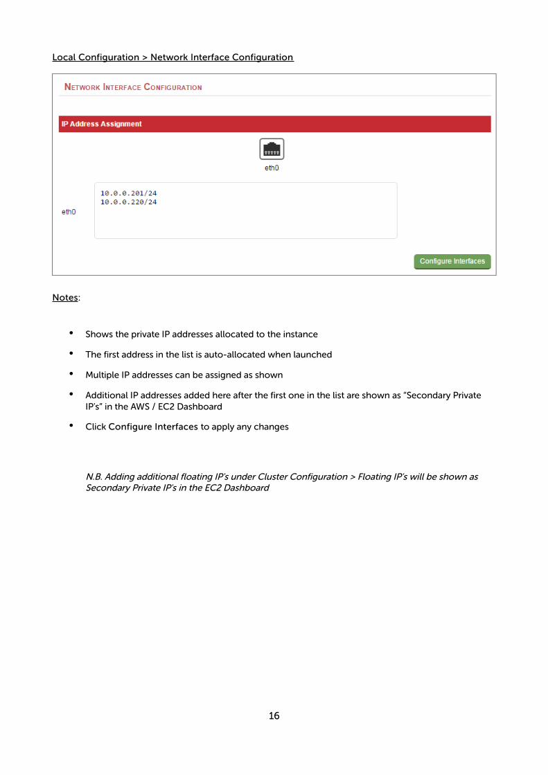
Local Configuration > Network Interface Configuration
Notes:
• Shows the private IP addresses allocated to the instance
• The first address in the list is auto-allocated when launched
• Multiple IP addresses can be assigned as shown
• Additional IP addresses added here after the first one in the list are shown as “Secondary Private IP's” in the AWS / EC2 Dashboard
• Click Configure Interfaces to apply any changes
N.B. Adding additional floating IP's under Cluster Configuration > Floating IP's will be shown as Secondary Private IP's in the EC2 Dashboard
16
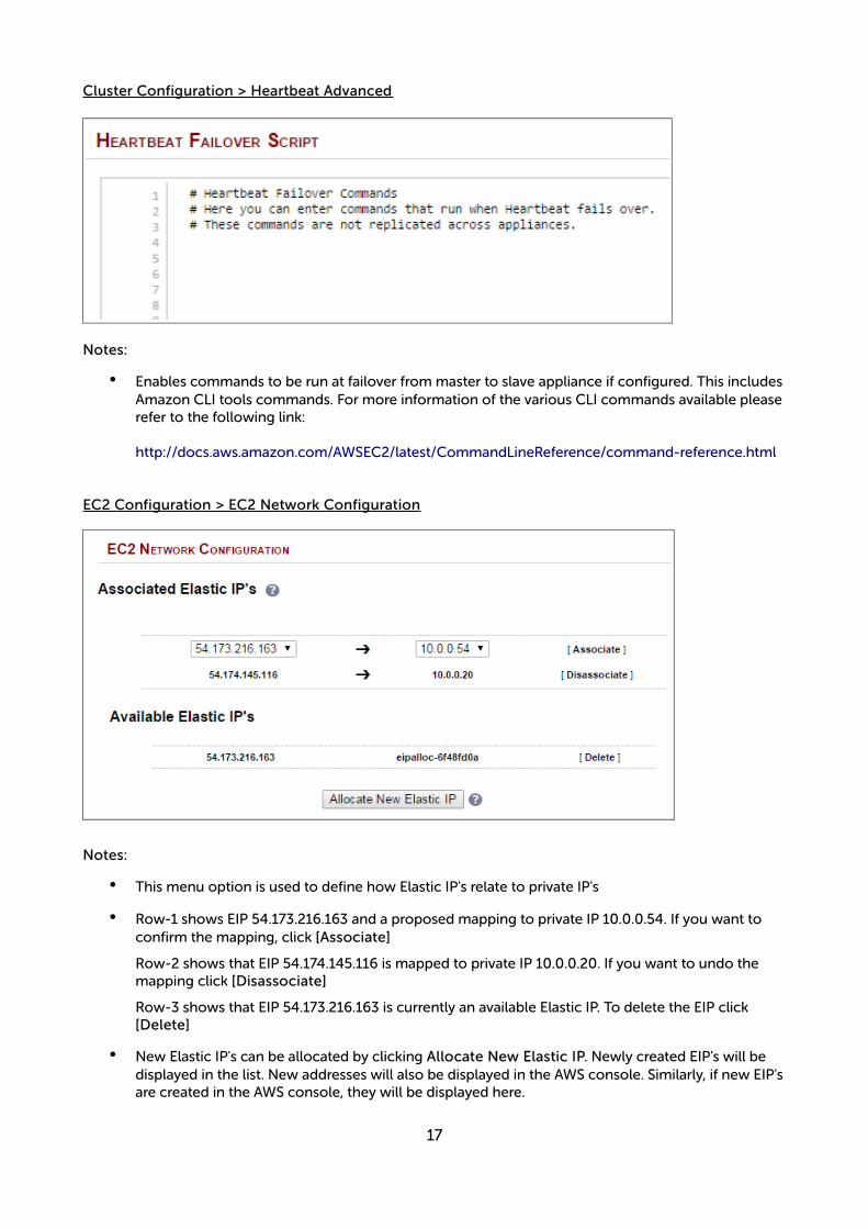
Cluster Configuration > Heartbeat Advanced
Notes:
• Enables commands to be run at failover from master to slave appliance if configured. This includesAmazon CLI tools commands. For more information of the various CLI commands available pleaserefer to the following link:
http://docs.aws.amazon.com/AWSEC2/latest/CommandLineReference/command-reference.html
EC2 Configuration > EC2 Network Configuration
Notes:
• This menu option is used to define how Elastic IP's relate to private IP's
• Row-1 shows EIP 54.173.216.163 and a proposed mapping to private IP 10.0.0.54. If you want to confirm the mapping, click [Associate]
Row-2 shows that EIP 54.174.145.116 is mapped to private IP 10.0.0.20. If you want to undo the mapping click [Disassociate]
Row-3 shows that EIP 54.173.216.163 is currently an available Elastic IP. To delete the EIP click [Delete]
• New Elastic IP's can be allocated by clicking Allocate New Elastic IP. Newly created EIP's will be displayed in the list. New addresses will also be displayed in the AWS console. Similarly, if new EIP'sare created in the AWS console, they will be displayed here.
17
Accessing the Appliance using SSH
This uses the private key that you downloaded when setting up your instance (please refer to page 13 of this guide). To connect to the load balancer using SSH, this private key must be used. Under Linux, the key can be used immediately, for PuTTY under Windows, the key must first be converted to a format required by PuTTY as detailed below.
N.B. For SSH access make sure that TCP port 22 is included in the security group for the load balancer
Using Linux
# First change the permission of the private key file to allow only the owner read access
chmod 400 /path-where-saved/ec2-key-name.pem
# Now connect via SSH specifying the private key file – login as user 'lbuser'
ssh -i /path-where-saved/ec2-key-name.pem [email protected]
or
ssh -i /path-where-saved/ec2-key-name.pem lbuser@dns-name
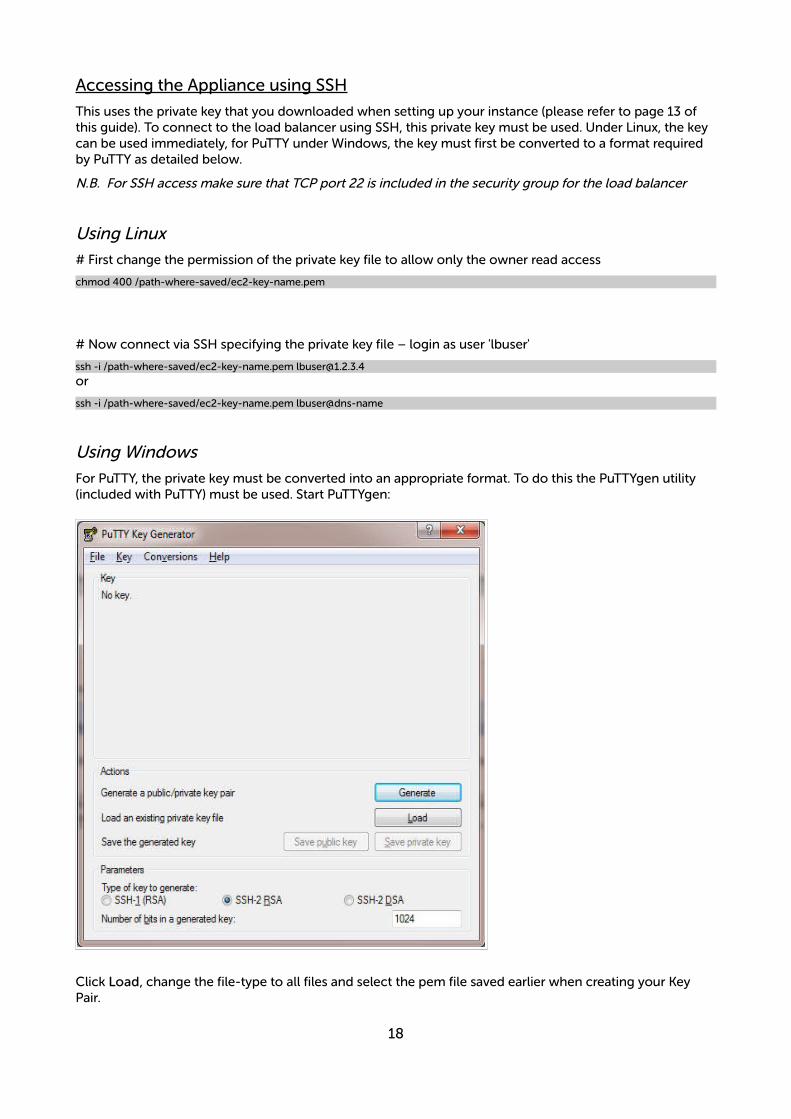
Using Windows
For PuTTY, the private key must be converted into an appropriate format. To do this the PuTTYgen utility (included with PuTTY) must be used. Start PuTTYgen:
Click Load, change the file-type to all files and select the pem file saved earlier when creating your Key Pair.
18

You should see the following message:
Click OK
Now Click Save private key – this can then be used with PuTTY.
19
NB. You can also choose to enter an additional pass-phrase for improved security, if you don't, the following message will be displayed:
Click Yes and save the file with the default .ppk extension
Now close PuTTYgen and start PuTTY
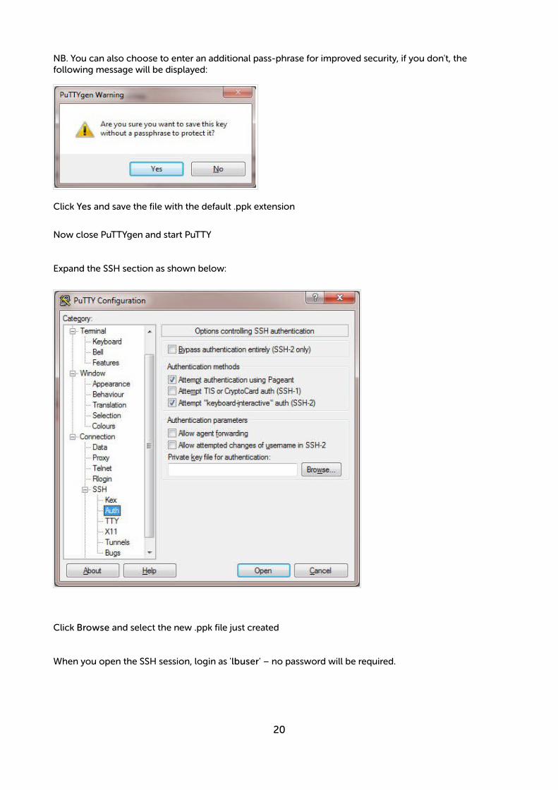
Expand the SSH section as shown below:
Click Browse and select the new .ppk file just created
When you open the SSH session, login as 'lbuser' – no password will be required.
20
Accessing the Appliance using SCP
Using Linux
# First change the permission of the private key file to allow only the owner read access
chmod 400 /path-where-saved/ec2-key-name.pem
# Now start SCP specifying the private key file – login as user 'lbuser'
scp -i /path-where-saved/ec2-key-name.pem <local-file> [email protected]:<remote-file>or
scp -i /path-where-saved/ec2-key-name.pem <local-file> lbuser@dns-name:<remote-file>
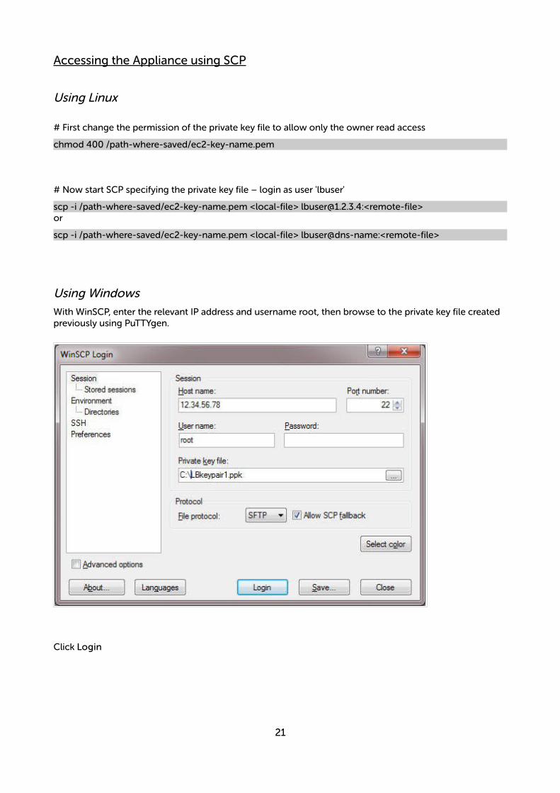
Using Windows
With WinSCP, enter the relevant IP address and username root, then browse to the private key file created previously using PuTTYgen.
Click Login
21
Configuration ExamplesThe following sections provide a number of examples to help illustrate how the load balancer can be deployed. In many cases, either example 1 or example 2 can be used. Both of these examples use a single subnet for the load balancer and the load balanced back-end (real) servers. The simplest is example 1 which uses a layer 7 configuration and requires no changes to the back-end servers. Example 2 uses a layer4 configuration and requires the default gateway of the back-end servers to be the load balancer.
It's important to consider that when configured at layer 7, the load balancer is not transparent which means that the source IP address of packets reaching the real servers will be the load balancer's own IP address. At layer 4, the load balancer is transparent which means that the source IP address of packets reaching the real servers is the client IP address.
Examples 3 – 7 illustrate how the load balancer can be configured to support other scenarios, e.g. when the real servers are located in a different subnet.
NOTE : It's not possible to configure a VIP on the same IP address as any of the network interfaces. This ensures services can move between master and slave instances.
1) Load balancing Web Servers – 1 Subnet, 1 Interface, Layer 7
This is a simple layer 7 example using one subnet for both the load balancer and the web servers. The load balancer has a single network interface.
a) Setting up AWS
• Deploy the load balancer instance as described on page 10-13
• Deploy your required web server instances into the same VPC & subnet as the load balancer
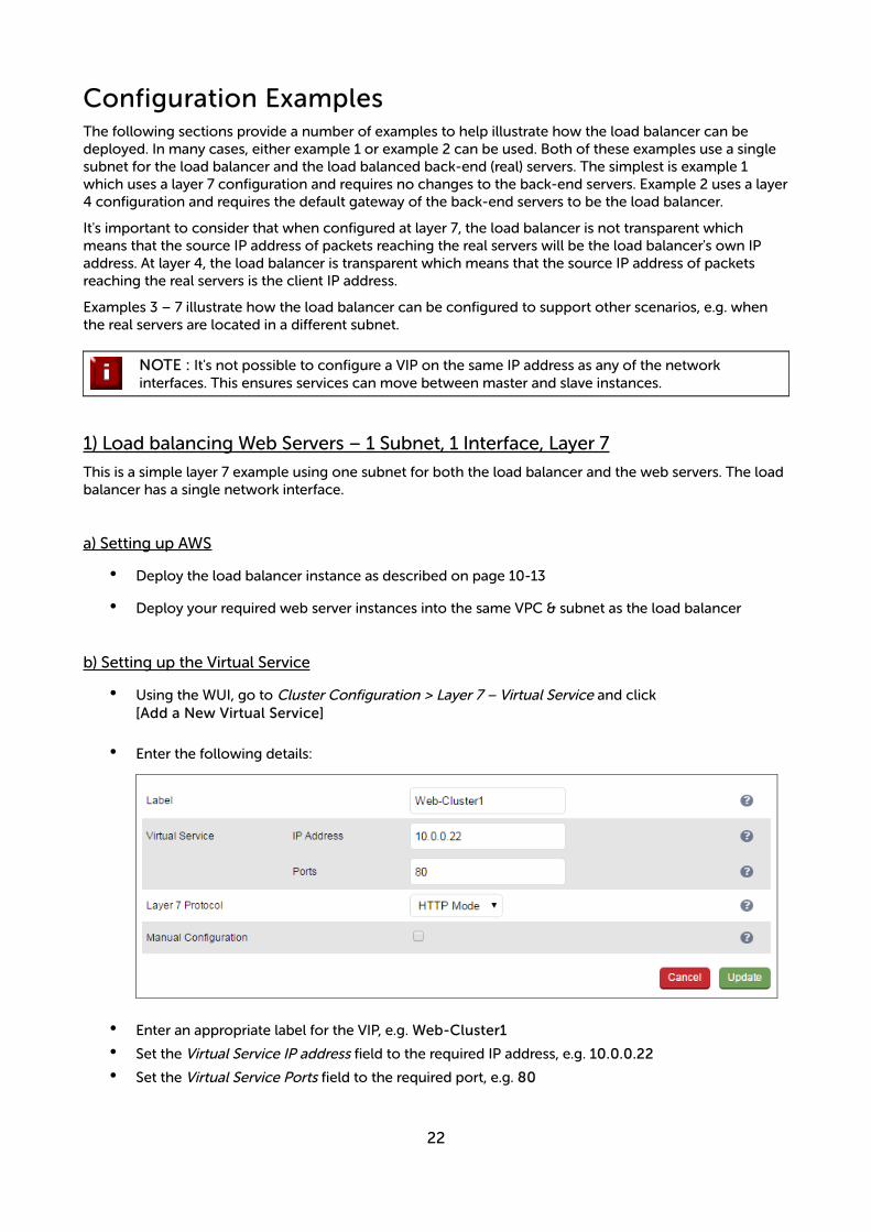
b) Setting up the Virtual Service
• Using the WUI, go to Cluster Configuration > Layer 7 – Virtual Service and click[Add a New Virtual Service]
• Enter the following details:
• Enter an appropriate label for the VIP, e.g. Web-Cluster1
• Set the Virtual Service IP address field to the required IP address, e.g. 10.0.0.22
• Set the Virtual Service Ports field to the required port, e.g. 80
22
• Leave Layer 7 Protocol set to HTTP Mode
• Click Update
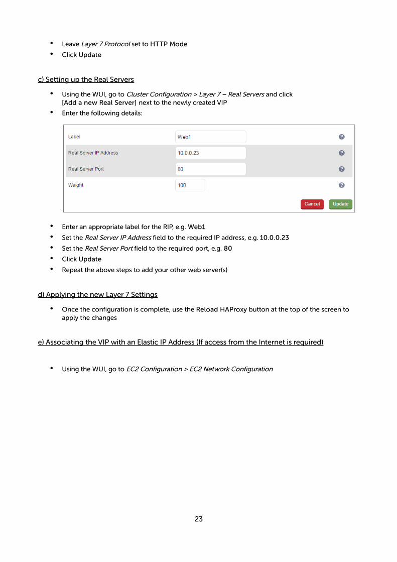
c) Setting up the Real Servers
• Using the WUI, go to Cluster Configuration > Layer 7 – Real Servers and click[Add a new Real Server] next to the newly created VIP
• Enter the following details:
• Enter an appropriate label for the RIP, e.g. Web1
• Set the Real Server IP Address field to the required IP address, e.g. 10.0.0.23
• Set the Real Server Port field to the required port, e.g. 80
• Click Update
• Repeat the above steps to add your other web server(s)
d) Applying the new Layer 7 Settings
• Once the configuration is complete, use the Reload HAProxy button at the top of the screen to apply the changes
e) Associating the VIP with an Elastic IP Address (If access from the Internet is required)
• Using the WUI, go to EC2 Configuration > EC2 Network Configuration
23

• Under the Associated Elastic IP's section click [Associate] next to the VIPs private IP address (10.0.0.22 in this case), if no Elastic IP's are available, use the Allocate New Elastic IP button to addone
24
2) Load balancing Web Servers - 1 Subnet, 1 Interface, Layer 4
This is a simple layer 4 example using one subnet for both the load balancer and the web servers. The default gateway on the web servers must be set to be the load balancer – this ensures that return traffic goes back to the client via the load balancer, which is a requirement of layer 4 NAT mode.
a) Setting up AWS
• Deploy the load balancer instance as described on page 10-13
• Deploy your required web server instances into the same VPC & subnet as the load balancer
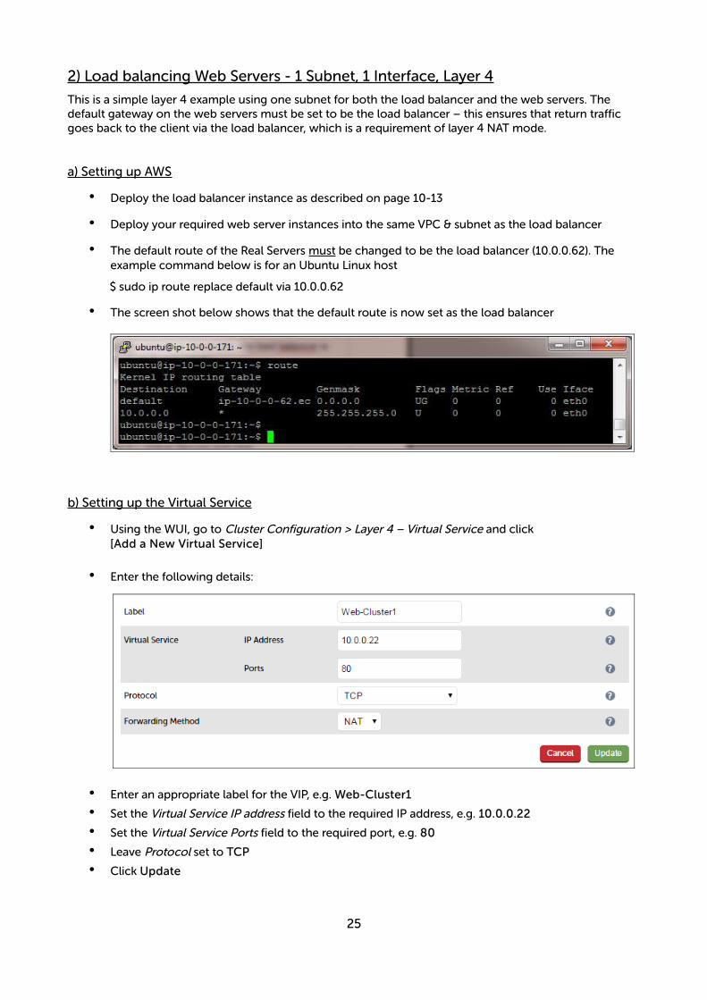
• The default route of the Real Servers must be changed to be the load balancer (10.0.0.62). The example command below is for an Ubuntu Linux host
$ sudo ip route replace default via 10.0.0.62
• The screen shot below shows that the default route is now set as the load balancer
b) Setting up the Virtual Service
• Using the WUI, go to Cluster Configuration > Layer 4 – Virtual Service and click[Add a New Virtual Service]
• Enter the following details:
• Enter an appropriate label for the VIP, e.g. Web-Cluster1
• Set the Virtual Service IP address field to the required IP address, e.g. 10.0.0.22
• Set the Virtual Service Ports field to the required port, e.g. 80
• Leave Protocol set to TCP
• Click Update
25

c) Setting up the Real Servers
• Using the WUI, go to Cluster Configuration > Layer 4 – Real Servers and click[Add a new Real Server] next to the newly created VIP
• Enter the following details:
• Enter an appropriate label for the RIP, e.g. Web1
• Change the Real Server IP Address field to the required IP address, e.g. 10.0.0.31
• Set Real Server Port to 80
• Click Update
• Repeat the above steps to add your other web servers(s)
d) Associating the VIP with an Elastic IP Address (If access from the Internet is required)
• Using the WUI, go to EC2 Configuration > EC2 Network Configuration
• Under the Associated Elastic IP's section click [Associate] next to the VIPs private IP address (10.0.0.22 in this case), if no Elastic IP's are available, use the Allocate New Elastic IP button to addone
26

e) Enable Internet Connectivity via the Load Balancer for the Real Servers (If Required)
If the Real Servers need to access the Internet, 'Autonat' must be enabled on the load balancer to enable this functionality.
• Using the WUI, go to Cluster Configuration > Layer 4 – Advanced Configuration
• Change the Auto-NAT setting to eth0
• Click Update
27
3) Load balancing Web Servers – 2 Subnets, 2 Interfaces, Layer 7
This example uses 2 subnets – the load balancer is configured with 2 interfaces - 1 interface in subnet 1 and the other in subnet 2. The real severs are connected to subnet 2.
a) Setting up AWS
• Deploy the load balancer instance as described on page 10-13
• Add a second subnet to your VPC, skip this step if you already have one
• Add a second Network Interface, associate it with the second subnet and attach it to the load balancer instance
• Deploy your required web server instances into the second subnet
b) Configuring the second Network Interface
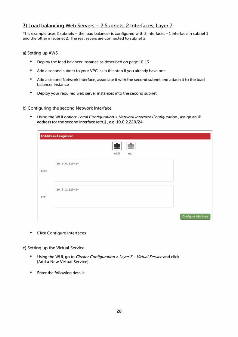
• Using the WUI option: Local Configuration > Network Interface Configuration , assign an IP address for the second interface (eth1) , e.g. 10.0.2.220/24
• Click Configure Interfaces
c) Setting up the Virtual Service
• Using the WUI, go to Cluster Configuration > Layer 7 – Virtual Service and click[Add a New Virtual Service]
• Enter the following details:
28
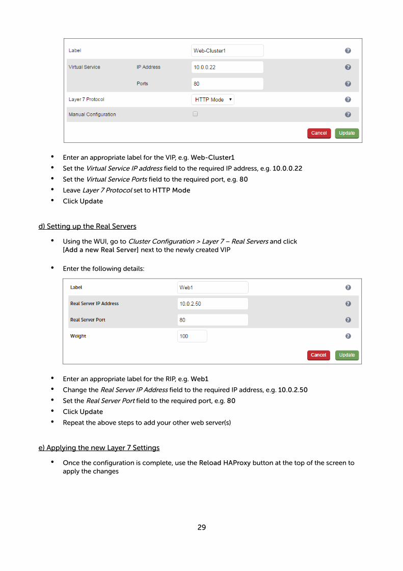
• Enter an appropriate label for the VIP, e.g. Web-Cluster1
• Set the Virtual Service IP address field to the required IP address, e.g. 10.0.0.22
• Set the Virtual Service Ports field to the required port, e.g. 80
• Leave Layer 7 Protocol set to HTTP Mode
• Click Update
d) Setting up the Real Servers
• Using the WUI, go to Cluster Configuration > Layer 7 – Real Servers and click[Add a new Real Server] next to the newly created VIP
• Enter the following details:
• Enter an appropriate label for the RIP, e.g. Web1
• Change the Real Server IP Address field to the required IP address, e.g. 10.0.2.50
• Set the Real Server Port field to the required port, e.g. 80
• Click Update
• Repeat the above steps to add your other web server(s)
e) Applying the new Layer 7 Settings
• Once the configuration is complete, use the Reload HAProxy button at the top of the screen to apply the changes
29
f) Associating the VIP with an Elastic IP Address (If access from the Internet is required)
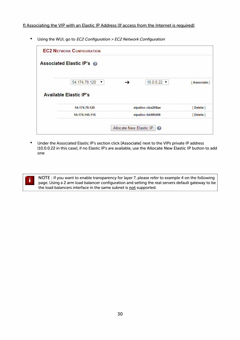
• Using the WUI, go to EC2 Configuration > EC2 Network Configuration
• Under the Associated Elastic IP's section click [Associate] next to the VIPs private IP address (10.0.0.22 in this case), if no Elastic IP's are available, use the Allocate New Elastic IP button to addone
NOTE : If you want to enable transparency for layer 7, please refer to example 4 on the following page. Using a 2 arm load balancer configuration and setting the real servers default gateway to bethe load balancers interface in the same subnet is not supported.
30
4) Load balancing Web Servers - 2 Subnets, 1 Interface, Layer 7 with Transparency
This example uses 2 subnets - one subnet for the load balancer and one subnet for the web servers. The load balancer has a single network interface located in the first subnet. Layer 7 transparency is enabled to ensure that the source IP address of packets reaching the web servers is the source IP of the clients and not the IP address of the load balancer. Routing rules for the second subnet must also be changed.
a) Setting up AWS
• Deploy the load balancer instance as described on page 10-13
• Add a second subnet to your VPC, skip this step if you already have one
• Deploy your required web server instances into the second subnet
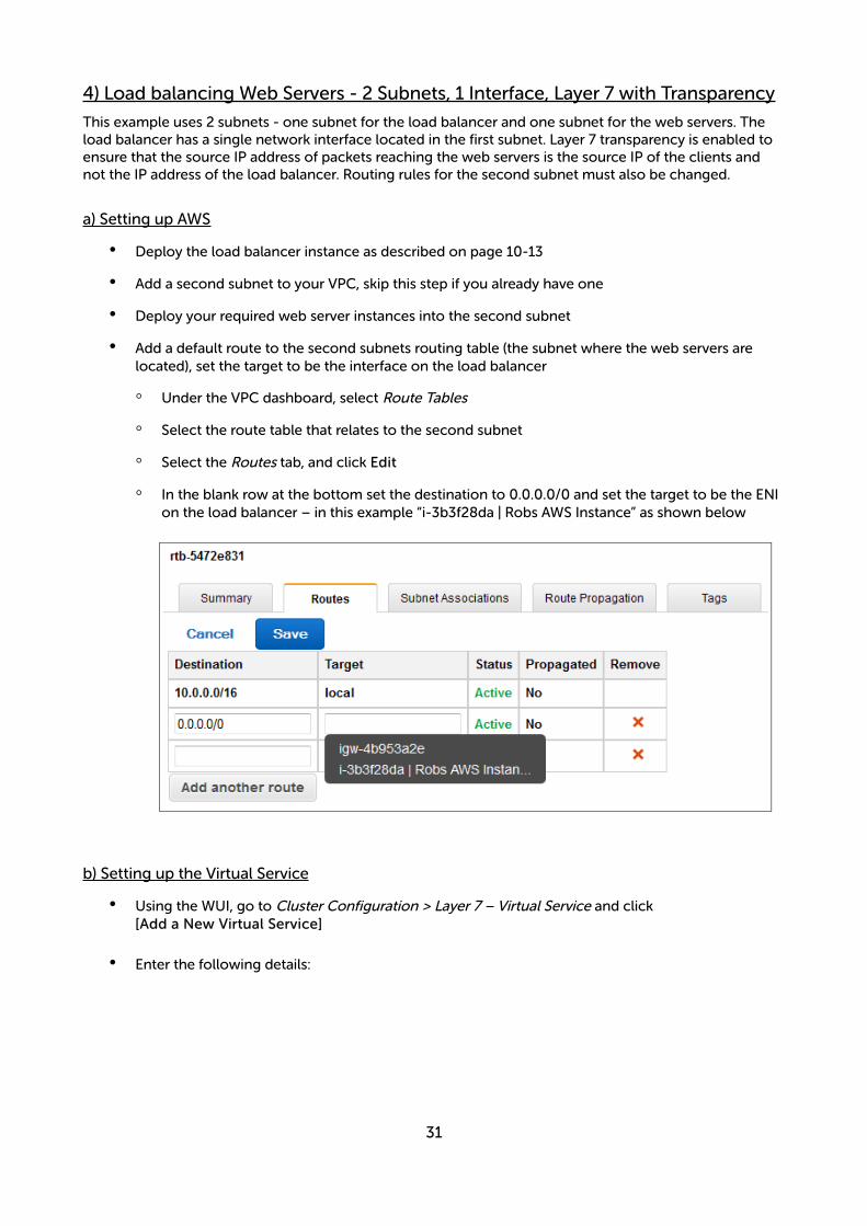
• Add a default route to the second subnets routing table (the subnet where the web servers are located), set the target to be the interface on the load balancer
◦ Under the VPC dashboard, select Route Tables
◦ Select the route table that relates to the second subnet
◦ Select the Routes tab, and click Edit
◦ In the blank row at the bottom set the destination to 0.0.0.0/0 and set the target to be the ENI on the load balancer – in this example “i-3b3f28da | Robs AWS Instance” as shown below
b) Setting up the Virtual Service
• Using the WUI, go to Cluster Configuration > Layer 7 – Virtual Service and click[Add a New Virtual Service]
• Enter the following details:
31
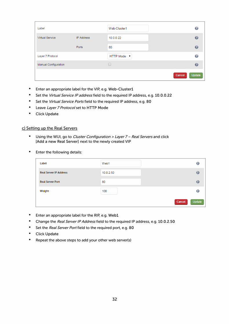
• Enter an appropriate label for the VIP, e.g. Web-Cluster1
• Set the Virtual Service IP address field to the required IP address, e.g. 10.0.0.22
• Set the Virtual Service Ports field to the required IP address, e.g. 80
• Leave Layer 7 Protocol set to HTTP Mode
• Click Update
c) Setting up the Real Servers
• Using the WUI, go to Cluster Configuration > Layer 7 – Real Servers and click[Add a new Real Server] next to the newly created VIP
• Enter the following details:
• Enter an appropriate label for the RIP, e.g. Web1
• Change the Real Server IP Address field to the required IP address, e.g. 10.0.2.50
• Set the Real Server Port field to the required port, e.g. 80
• Click Update
• Repeat the above steps to add your other web server(s)
32
d) Configuring Layer 7 – Advanced Settings
• Using the WUI, go to Cluster Configuration > Layer 7 – Advanced Configuration
• Enable (check) Transparent Proxy
• Click Update
e) Applying the new Layer 7 Settings
• Once the configuration is complete, use the Reload HAProxy button at the top of the screen to apply the changes
f) Associating the VIP with an Elastic IP Address (If access from the Internet is required)
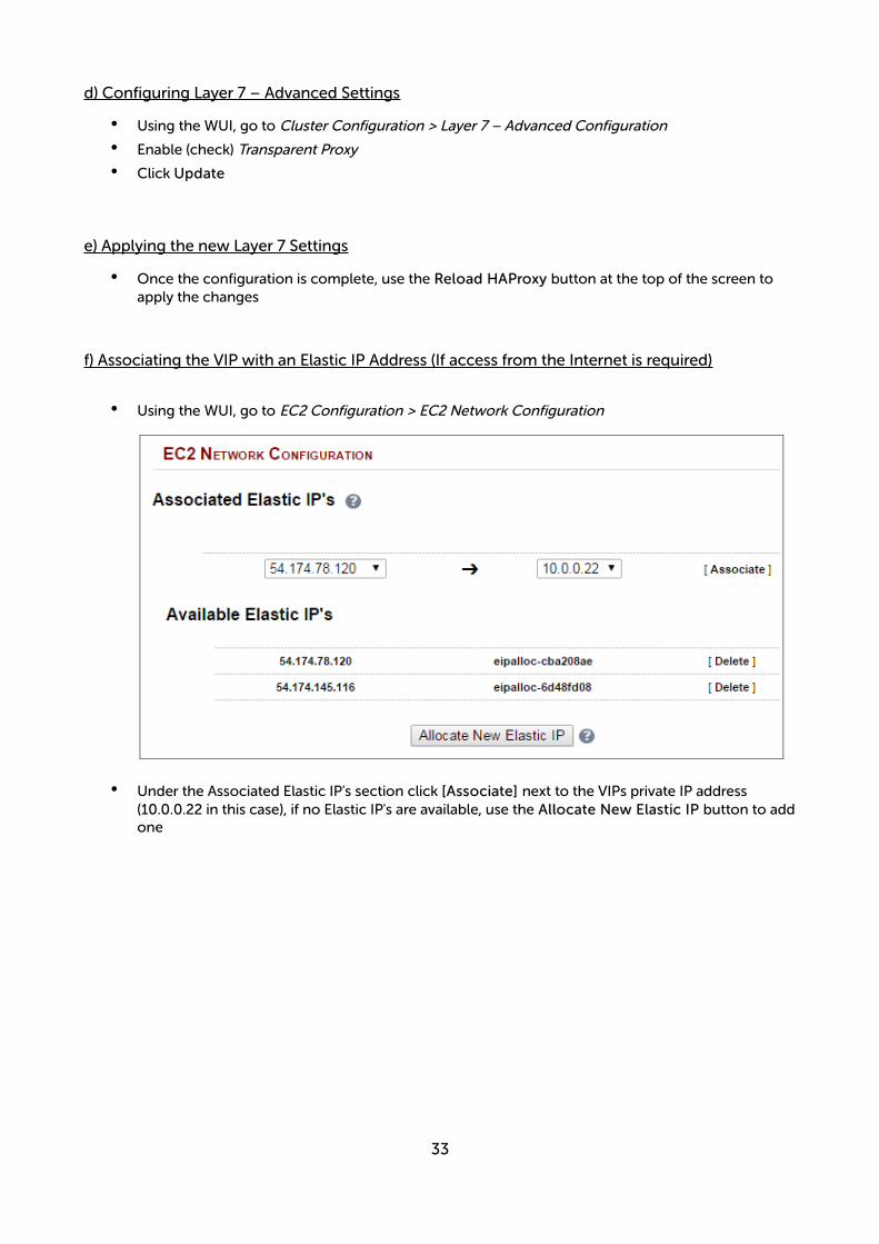
• Using the WUI, go to EC2 Configuration > EC2 Network Configuration
• Under the Associated Elastic IP's section click [Associate] next to the VIPs private IP address (10.0.0.22 in this case), if no Elastic IP's are available, use the Allocate New Elastic IP button to addone
33
5) Load balancing Web Servers - 1 Subnet, 1 Interface, Layer 7 with SSL Termination
This is the same as example 1 with the addition of SSL termination on the load balancer.
We generally recommend that SSL should be terminated on the backend servers rather than the load balancer for scalability reasons.
a) Setting up AWS
• Deploy the load balancer instance as described on page 10-13
• Deploy your required web server instances into the same VPC & subnet as the load balancer
b) Setting up the Virtual Service
• Using the WUI, go to Cluster Configuration > Layer 7 – Virtual Service and click[Add a New Virtual Service]
• Enter the following details:
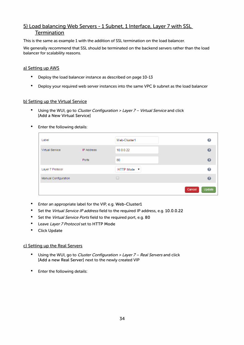
• Enter an appropriate label for the VIP, e.g. Web-Cluster1
• Set the Virtual Service IP address field to the required IP address, e.g. 10.0.0.22
• Set the Virtual Service Ports field to the required port, e.g. 80
• Leave Layer 7 Protocol set to HTTP Mode
• Click Update
c) Setting up the Real Servers
• Using the WUI, go to Cluster Configuration > Layer 7 – Real Servers and click[Add a new Real Server] next to the newly created VIP
• Enter the following details:
34
• Enter an appropriate label for the RIP, e.g. Web1
• Change the Real Server IP Address field to the required IP address, e.g. 10.0.0.23
• Set the Real Server Port field to the required port, e.g. 80
• Click Update
• Repeat the above steps to add your other web server(s)
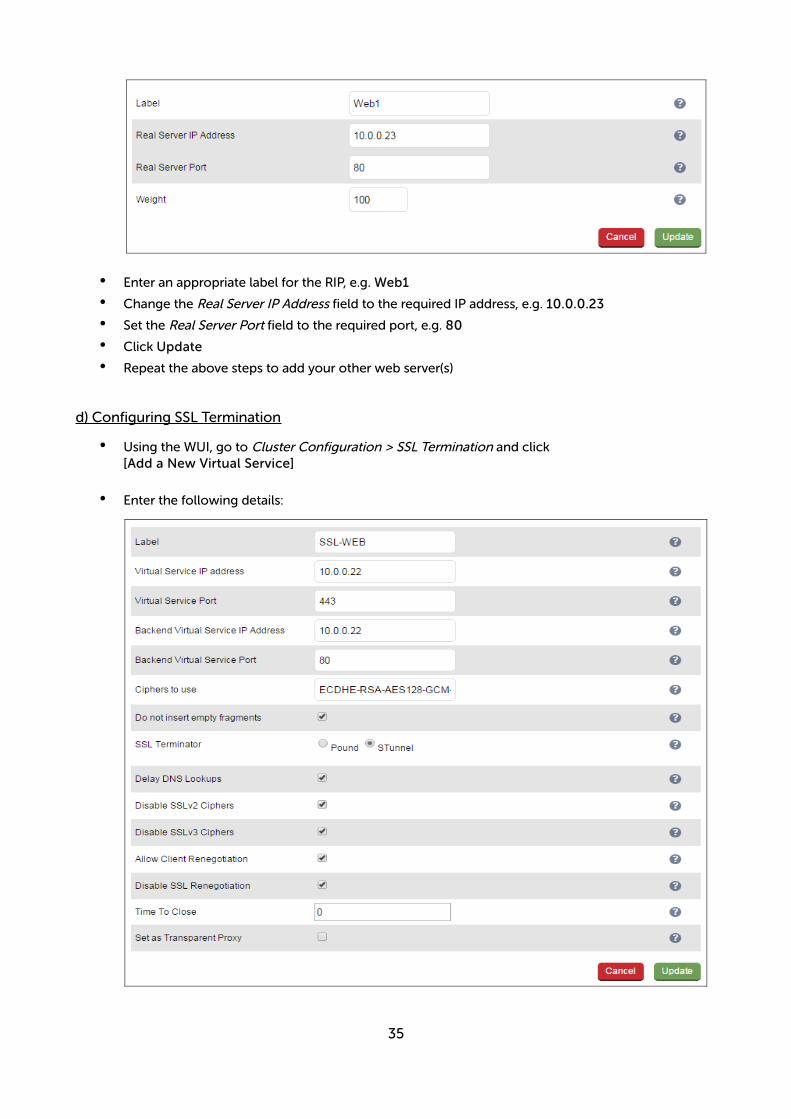
d) Configuring SSL Termination
• Using the WUI, go to Cluster Configuration > SSL Termination and click[Add a New Virtual Service]
• Enter the following details:
35

• Enter an appropriate label for the VIP, e.g. SSL-WEB
• Set the Virtual Service IP address to be the same as the VIP created in step (c) e.g. 10.0.0.22
• Set the Virtual Service Ports field to 443
• Set the Backend Virtual Service IP address to be the same as the VIP created in step (c) e.g. 10.0.0.22
• Set the Backend Virtual Service Ports field to 80
• Leave all other settings at their default values
• Click Update
SSL Certificate Notes:
• A default self-signed certificate is used when SSL virtual services are first defined
• To change this, using the WUI, select: Cluster Configuration > SSL Termination
• Click [Certificate] next to the Virtual Service
• If you already have a certificate, use the Upload prepared PEM/PFX file option at the bottom of the screen to upload it
• If you don't have a certificate, you can create a CSR using the Generate SSL Certificate Request section. This will create the CSR in the upper pane of the Upload Signed Certificate section basedon the settings you enter. This should be copied and sent to your CA
• Once the signed certificate is received, copy/paste it (along with any required intermediate certificates) into the lower pane of the Upload Signed Certificate section, and click the Upload Signed Certificate button
e) Applying the new Settings
• Once the configuration is complete, use the Reload HAProxy button at the top of the screen to apply the changes
• Once the configuration is complete, use the Restart Stunnel button at the top of the screen to apply the changes
f) Associating the VIP with an Elastic IP Address (If access from the Internet is required)
• Using the WUI, go to EC2 Configuration > EC2 Network Configuration
36

• Under the Associated Elastic IP's section click [Associate] next to the VIPs private IP address (10.0.0.22 in this case), if no Elastic IP's are available, use the Allocate New Elastic IP button to addone
37
6) Load balancing RD Session Hosts - 2 Subnets, 1 Interface, Layer 7
This example uses 2 subnets - one subnet for the load balancer and one subnet for the session hosts. The load balancer has a single network interface located in the first subnet. Routing rules for the second subnet where the session hosts are located must also be changed.
a) Setting up AWS
• Deploy the load balancer instance as described on page 10-13
• Add a second subnet to your VPC, skip this step if you already have one
• Deploy your required session host server instances into the second subnet
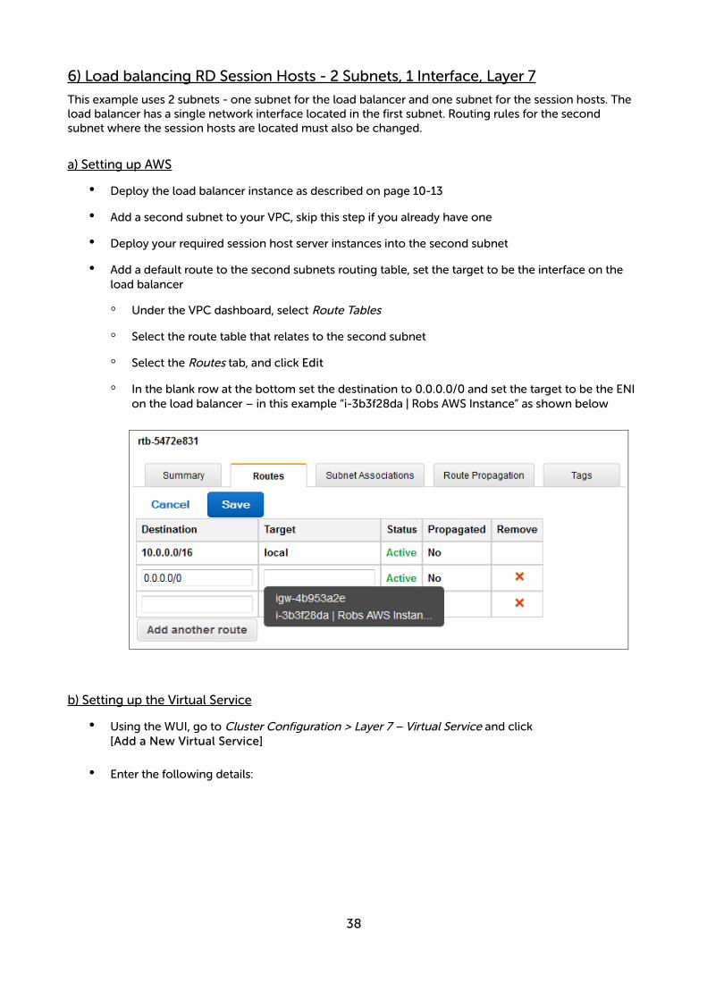
• Add a default route to the second subnets routing table, set the target to be the interface on the load balancer
◦ Under the VPC dashboard, select Route Tables
◦ Select the route table that relates to the second subnet
◦ Select the Routes tab, and click Edit
◦ In the blank row at the bottom set the destination to 0.0.0.0/0 and set the target to be the ENI on the load balancer – in this example “i-3b3f28da | Robs AWS Instance” as shown below
b) Setting up the Virtual Service
• Using the WUI, go to Cluster Configuration > Layer 7 – Virtual Service and click[Add a New Virtual Service]
• Enter the following details:
38
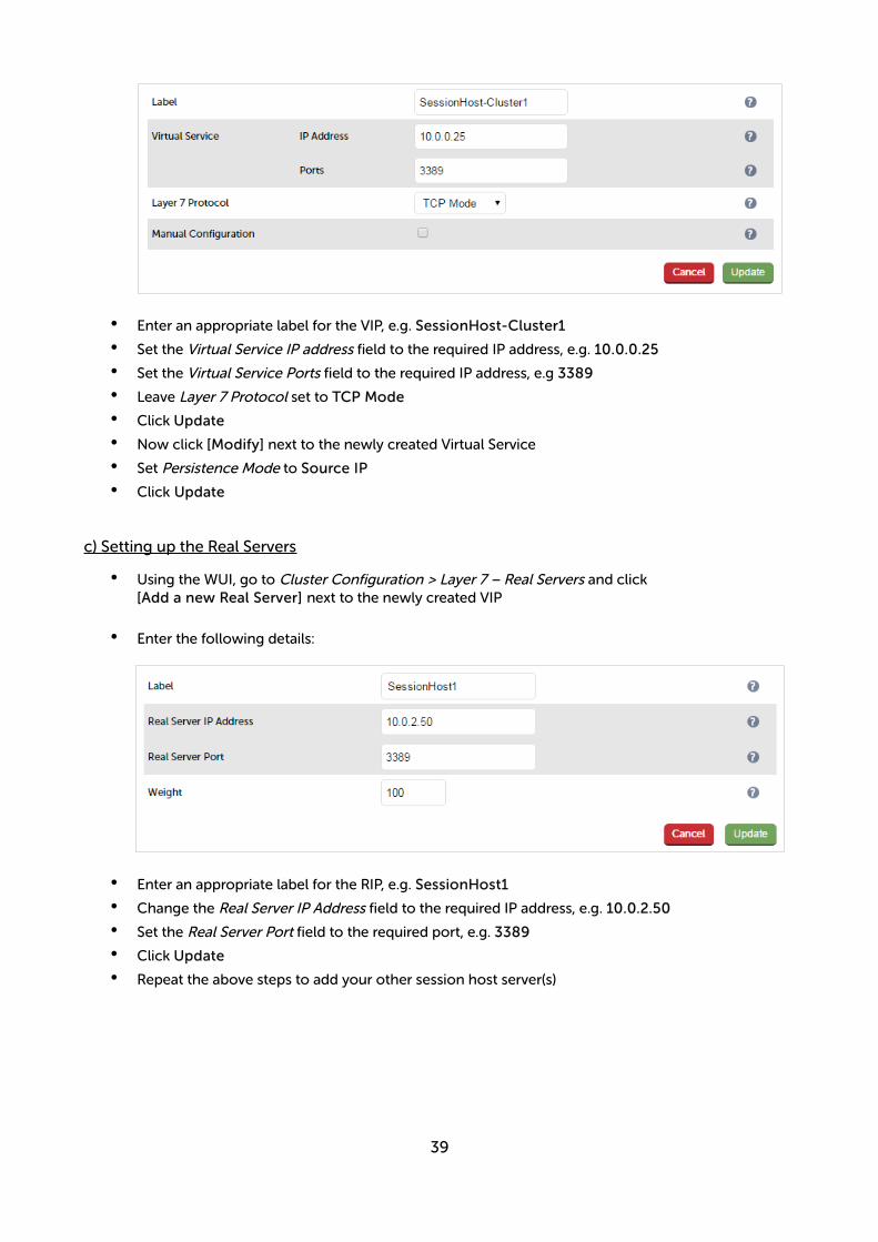
• Enter an appropriate label for the VIP, e.g. SessionHost-Cluster1
• Set the Virtual Service IP address field to the required IP address, e.g. 10.0.0.25
• Set the Virtual Service Ports field to the required IP address, e.g 3389
• Leave Layer 7 Protocol set to TCP Mode
• Click Update
• Now click [Modify] next to the newly created Virtual Service
• Set Persistence Mode to Source IP
• Click Update
c) Setting up the Real Servers
• Using the WUI, go to Cluster Configuration > Layer 7 – Real Servers and click[Add a new Real Server] next to the newly created VIP
• Enter the following details:
• Enter an appropriate label for the RIP, e.g. SessionHost1
• Change the Real Server IP Address field to the required IP address, e.g. 10.0.2.50
• Set the Real Server Port field to the required port, e.g. 3389
• Click Update
• Repeat the above steps to add your other session host server(s)
39
d) Applying the new Layer 7 Settings
• Once the configuration is complete, use the Reload HAProxy button at the top of the screen to apply the changes
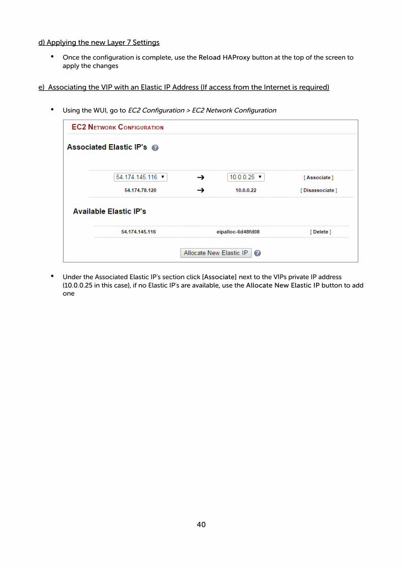
e) Associating the VIP with an Elastic IP Address (If access from the Internet is required)
• Using the WUI, go to EC2 Configuration > EC2 Network Configuration
• Under the Associated Elastic IP's section click [Associate] next to the VIPs private IP address (10.0.0.25 in this case), if no Elastic IP's are available, use the Allocate New Elastic IP button to addone
40
7) Load balancing Web Servers - 2 Subnets, 1 Interface, Layer 4
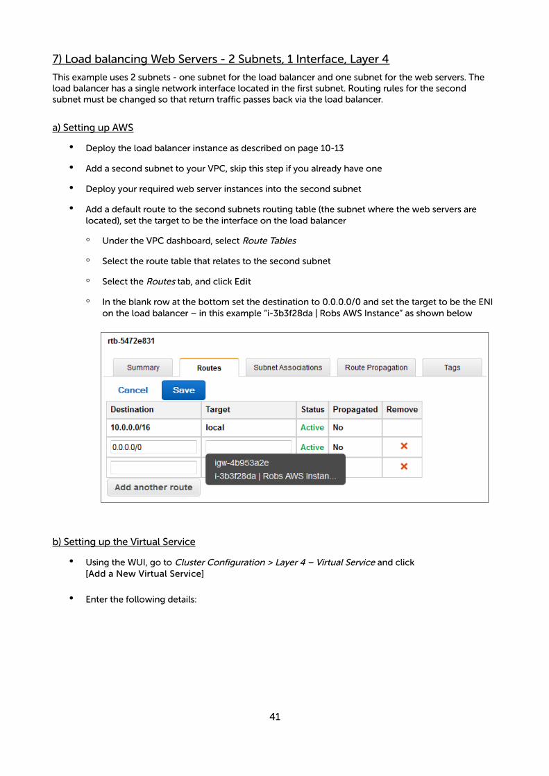
This example uses 2 subnets - one subnet for the load balancer and one subnet for the web servers. The load balancer has a single network interface located in the first subnet. Routing rules for the second subnet must be changed so that return traffic passes back via the load balancer.
a) Setting up AWS
• Deploy the load balancer instance as described on page 10-13
• Add a second subnet to your VPC, skip this step if you already have one
• Deploy your required web server instances into the second subnet
• Add a default route to the second subnets routing table (the subnet where the web servers are located), set the target to be the interface on the load balancer
◦ Under the VPC dashboard, select Route Tables
◦ Select the route table that relates to the second subnet
◦ Select the Routes tab, and click Edit
◦ In the blank row at the bottom set the destination to 0.0.0.0/0 and set the target to be the ENI on the load balancer – in this example “i-3b3f28da | Robs AWS Instance” as shown below
b) Setting up the Virtual Service
• Using the WUI, go to Cluster Configuration > Layer 4 – Virtual Service and click[Add a New Virtual Service]
• Enter the following details:
41
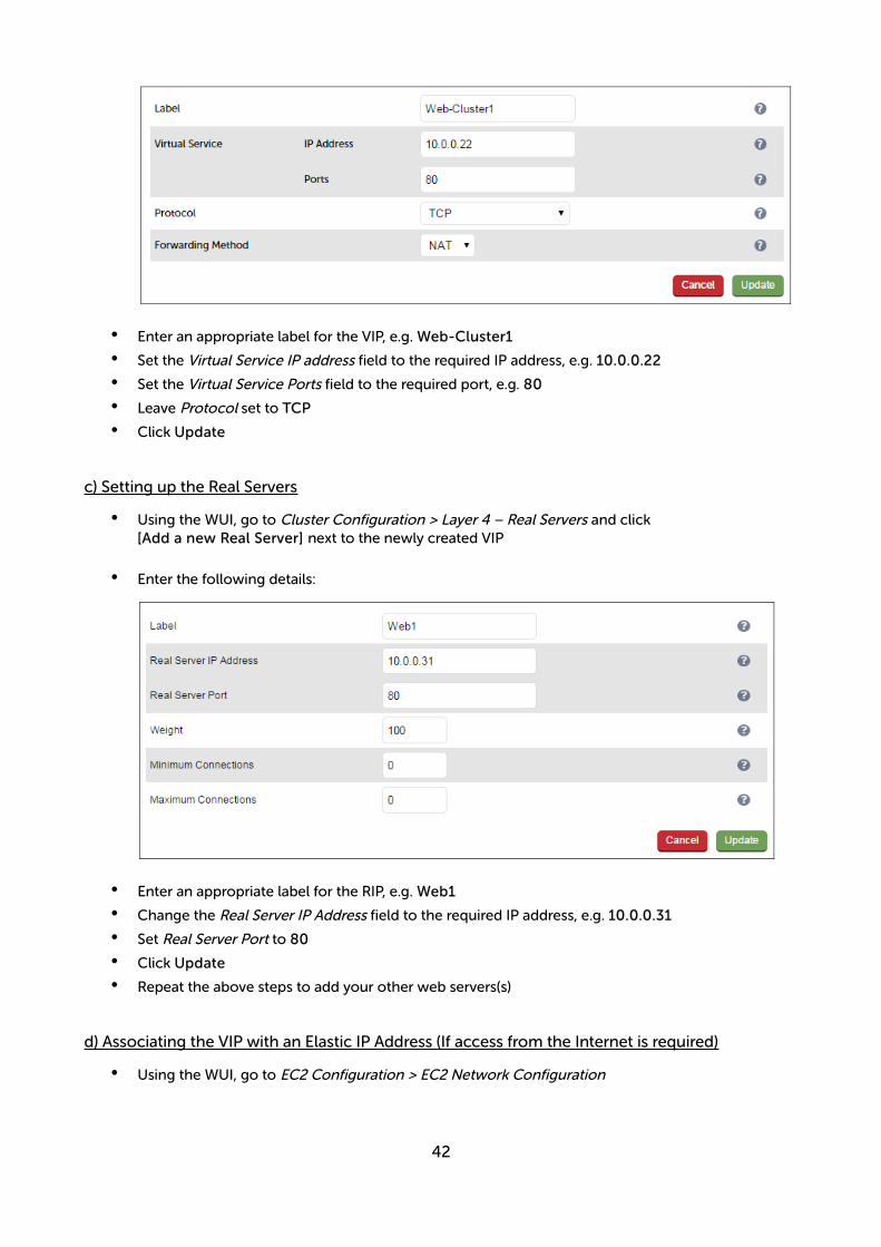
• Enter an appropriate label for the VIP, e.g. Web-Cluster1
• Set the Virtual Service IP address field to the required IP address, e.g. 10.0.0.22
• Set the Virtual Service Ports field to the required port, e.g. 80
• Leave Protocol set to TCP
• Click Update
c) Setting up the Real Servers
• Using the WUI, go to Cluster Configuration > Layer 4 – Real Servers and click[Add a new Real Server] next to the newly created VIP
• Enter the following details:
• Enter an appropriate label for the RIP, e.g. Web1
• Change the Real Server IP Address field to the required IP address, e.g. 10.0.0.31
• Set Real Server Port to 80
• Click Update
• Repeat the above steps to add your other web servers(s)
d) Associating the VIP with an Elastic IP Address (If access from the Internet is required)
• Using the WUI, go to EC2 Configuration > EC2 Network Configuration
42

• Under the Associated Elastic IP's section click [Associate] next to the VIPs private IP address (10.0.0.22 in this case), if no Elastic IP's are available, use the Allocate New Elastic IP button to addone
e) Enable Internet Connectivity via the Load Balancer for the Real Servers (If Required)
If the Real Servers need to access the Internet, 'Autonat' must be enabled on the load balancer to enable this functionality.
• Using the WUI, go to Cluster Configuration > Layer 4 – Advanced Configuration
• Change the Auto-NAT setting to eth0
• Click Update
43

Testing & Validation
Testing Load Balanced Services
For example, to test a web server based configuration, add a page to each web servers root directory e.g. test.html and put the server name on this page for easy identification during the tests.
Use two or more clients to do the testing. Open up a web browser on each test clients and enter the URL for the VIP e.g. http://192.168.110.10
Provided that persistence is disabled, each client should see a different server name because of the load balancing algorithm in use , i.e. they are being load balanced across the cluster.
Why test using two clients? If you use a single client it will most likely keep on hitting the same server for multiple requests. This is to do with the way that the load balancing algorithms are optimized.
Diagnosing VIP Connection Problems
1. Make sure that the device is active - this can be checked in the WUI. For a single appliance, the status bar should report Master & Active as shown below:
2. Check that the VIP/floating IP is up - Using View Configuration > Network Configuration verify that the VIP is active on the load balancer, if not check Logs > Heartbeat for errors.
eth0: <BROADCAST,MULTICAST,UP,LOWER_UP> mtu 9001 qdisc pfifo_fast state UP qlen 1000 link/ether 02:bd:88:12:2f:5b brd ff:ff:ff:ff:ff:ff inet 10.0.0.220/24 brd 10.0.0.255 scope global eth0 valid_lft forever preferred_lft forever inet 10.0.0.22/24 brd 10.0.0.255 scope global secondary eth0 valid_lft forever preferred_lft forever inet6 fe80::bd:88ff:fe12:2f5b/64 scope link valid_lft forever preferred_lft forever
The above example shows that the interface (10.0.0.220) and VIP address (10.0.0.22) are both up.
3. Check that the Real Servers are up - Using System Overview make sure that none of your VIPs are colored red. If they are, the entire cluster is down (i.e. all Real Servers). Green indicates a healthy cluster, yellow indicates that your cluster may need attention (one or more of the Real Servers may be down), and blue indicates all Real Server have been deliberately taken offline (by using either Halt or Drain).
44
4. Check the connection state -
For layer 4 NAT mode VIPs check Reports > Layer 4 Current Connections to view the current traffic in detail. Any packets with state SYN_RECV often implies a return traffic routing issue
for single subnet Layer 4 mode make sure that the default gateway on all real servers is set to be →the load balancer
for dual subnet Layer 4 mode make sure that routing on the second subnet has been configured →correctly
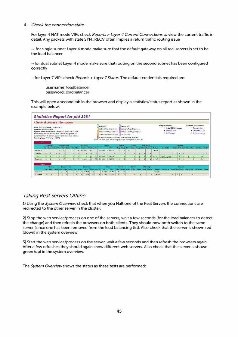
for Layer 7 VIPs check → Reports > Layer 7 Status. The default credentials required are:
username: loadbalancerpassword: loadbalancer
This will open a second tab in the browser and display a statistics/status report as shown in theexample below:
Taking Real Servers Offline
1) Using the System Overview check that when you Halt one of the Real Servers the connections are redirected to the other server in the cluster.
2) Stop the web service/process on one of the servers, wait a few seconds (for the load balancer to detect the change) and then refresh the browsers on both clients. They should now both switch to the same server (since one has been removed from the load balancing list). Also check that the server is shown red (down) in the system overview.
3) Start the web service/process on the server, wait a few seconds and then refresh the browsers again. After a few refreshes they should again show different web servers. Also check that the server is shown green (up) in the system overview.
The System Overview shows the status as these tests are performed:
45
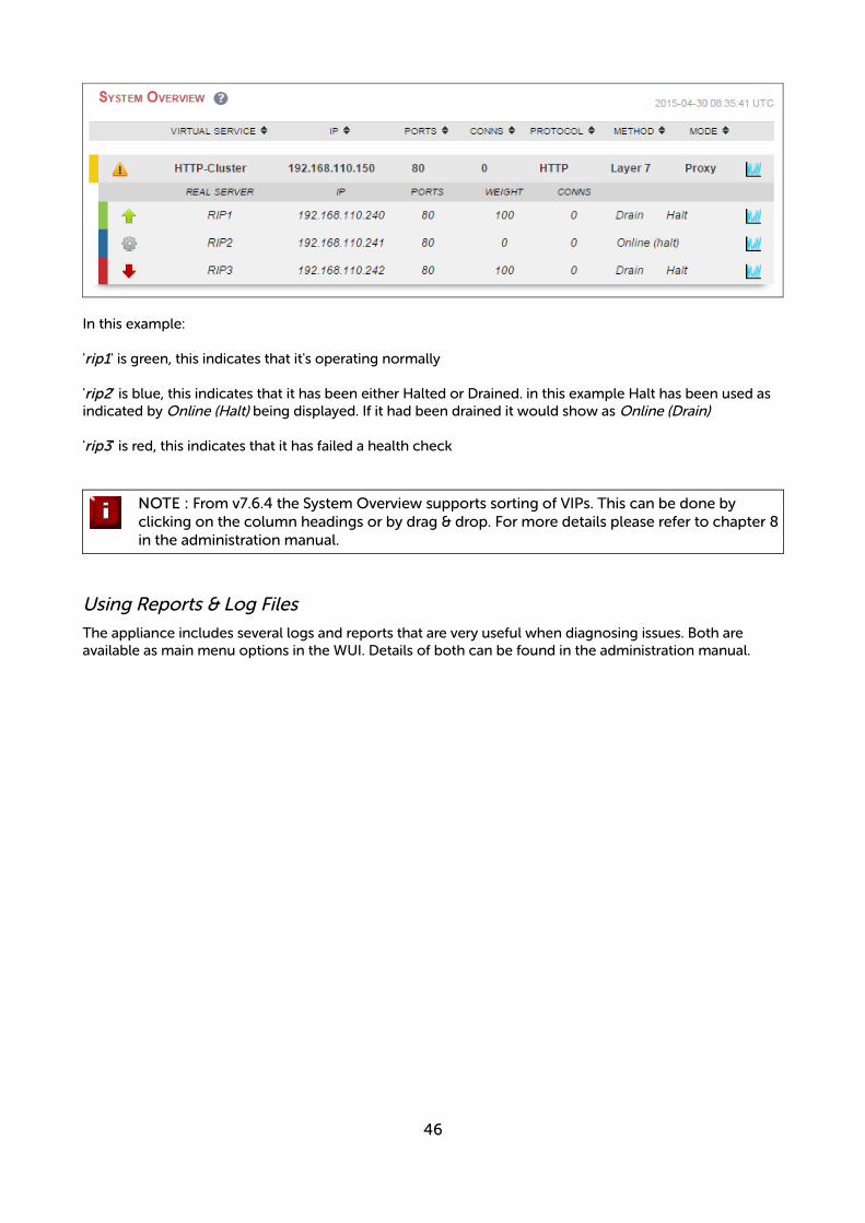
In this example:
'rip1' is green, this indicates that it's operating normally
'rip2' is blue, this indicates that it has been either Halted or Drained. in this example Halt has been used as indicated by Online (Halt) being displayed. If it had been drained it would show as Online (Drain)
'rip3' is red, this indicates that it has failed a health check
NOTE : From v7.6.4 the System Overview supports sorting of VIPs. This can be done by clicking on the column headings or by drag & drop. For more details please refer to chapter 8in the administration manual.
Using Reports & Log Files
The appliance includes several logs and reports that are very useful when diagnosing issues. Both are available as main menu options in the WUI. Details of both can be found in the administration manual.
46

Configuring High Availability using two Instances (Master & Slave)
Enterprise AWS supports HA mode using two instances configured as a clustered pair. In this mode, one device is active (typically the master appliance) and the other is passive (typically the slave appliance). If theactive device fails for any reason, the passive device will take over.
NOTE : This procedure assumes the first appliance is already up and running, and that this appliance will be the master unit of the clustered pair.
Step 1 – Deploy a second Instance & Configure the Source/Dest. Check
• Please refer to the steps on pages 10-13.
• Right-click the instance and select: Networking > Change Source/Dest. Check and ensure this is disabled
Step 2 – Prepare both instances for pairing
• Using the WUI option: Local configuration > Execute Shell Command run the following command on both appliances:
lb_enable_root enable
Step 3 – Verify Security Group Settings
Ensure that the security group used by both instances has the following rules defined. These are required to ensure that heartbeat (used for HA communication) can communicate between the two instances.
Rule 1Type: Custom UDP ruleProtocol: UDPPort Range: 6694Source: Anywhere (or lockdown further if preferred)
Rule 2Type: Custom ICMP ruleProtocol: Echo RequestPort Range: N/ASource: Anywhere (or lockdown further if preferred)
N.B. Make sure you select ICMP Echo Request rather than ICMP Echo Reply
47

Step 4 – Configure Heartbeat Failover Script (Applies to Layer 4 NAT mode and Layer 7 with Tproxy)
For Layer 4 NAT mode, or Layer 7 mode with Tproxy enabled, AWS routing rules must be configured so that the load balancer is the default gateway. To enable successful failover to the slave device, these routing rules must then be changed to route via the slave instance. To set this up:
• On the master instance select the menu option: Cluster Configuration > Heartbeat Advanced and add the following line:
ec2-replace-route rtb-15127270 -r 0.0.0.0/0 -i i-f40efc59 --region eu-west-1
(change rtb-15127270 to the Route Table ID of the table associated with your real servers subnet)(change i-f40efc59 to the Instance-Id of your master instance)(change eu-west-1 to your region)
this sets the default route for the routing table associated with the subnet where your real servers are located to be the master instance. It's run automatically each time the master becomes active
• On the slave instance select the menu option: Cluster Configuration > Heartbeat Advanced and add the following line:
ec2-replace-route rtb-15127270 -r 0.0.0.0/0 -i i-f45ejc53 --region eu-west-1
(change rtb-15127270 to the Route Table ID of the table associated with your real servers subnet)(change i-f40efc59 to the Instance-Id of your slave instance)(change eu-west-1 to your region)
this sets the default route for the routing table associated with the subnet where your real servers are located to be the master instance. It's run automatically each time the slave becomes active
Step 5 – Configure High-Availability
• Connect to the WUI on the master unit
• Select the menu option: Cluster Configuration > High Availability Configuration
• In the IP address of new peer field, enter the slave appliances private IP address
• In the Password for loadbalancer user on peer field enter the Instance-ID of the slave appliance
• Click Add new node
• Once the pairing configuration has finished, any required service restart messages and the confirmed pair message will be displayed as shown below:
48
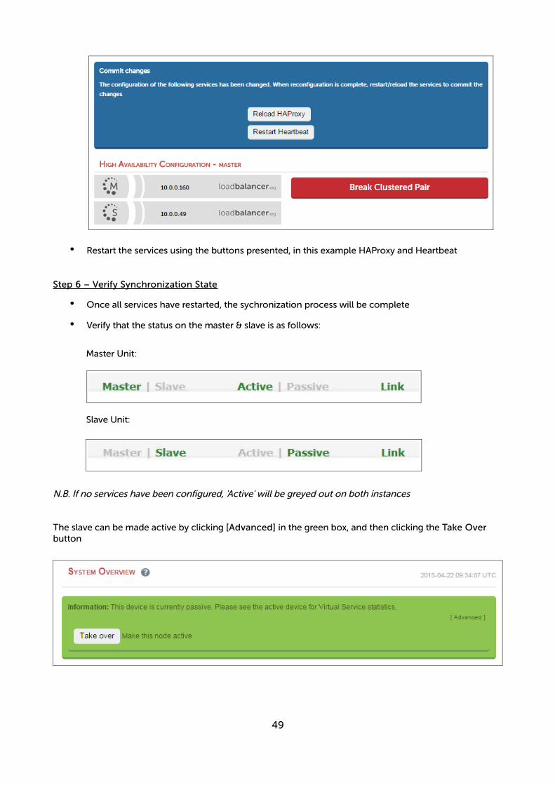
• Restart the services using the buttons presented, in this example HAProxy and Heartbeat
Step 6 – Verify Synchronization State
• Once all services have restarted, the sychronization process will be complete
• Verify that the status on the master & slave is as follows:
Master Unit:
Slave Unit:
N.B. If no services have been configured, 'Active' will be greyed out on both instances
The slave can be made active by clicking [Advanced] in the green box, and then clicking the Take Over button
49
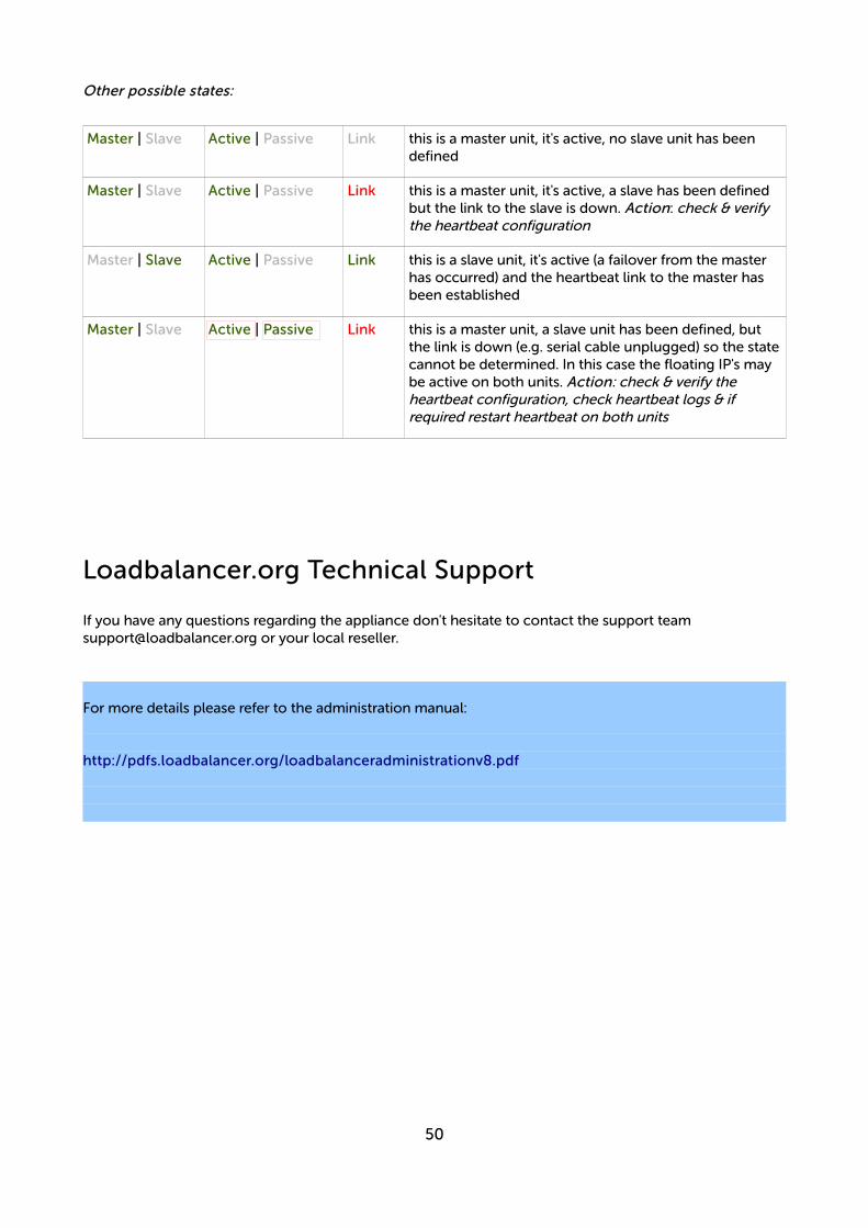
Other possible states:
Master | Slave Active | Passive Link this is a master unit, it's active, no slave unit has been defined
Master | Slave Active | Passive Link this is a master unit, it's active, a slave has been defined but the link to the slave is down. Action: check & verify the heartbeat configuration
Master | Slave Active | Passive Link this is a slave unit, it's active (a failover from the master has occurred) and the heartbeat link to the master has been established
Master | Slave Active | Passive Link this is a master unit, a slave unit has been defined, but the link is down (e.g. serial cable unplugged) so the statecannot be determined. In this case the floating IP's may be active on both units. Action: check & verify the heartbeat configuration, check heartbeat logs & if required restart heartbeat on both units
Loadbalancer.org Technical Support
If you have any questions regarding the appliance don't hesitate to contact the support team [email protected] or your local reseller.
For more details please refer to the administration manual:
http://pdfs.loadbalancer.org/loadbalanceradministrationv8.pdf
50
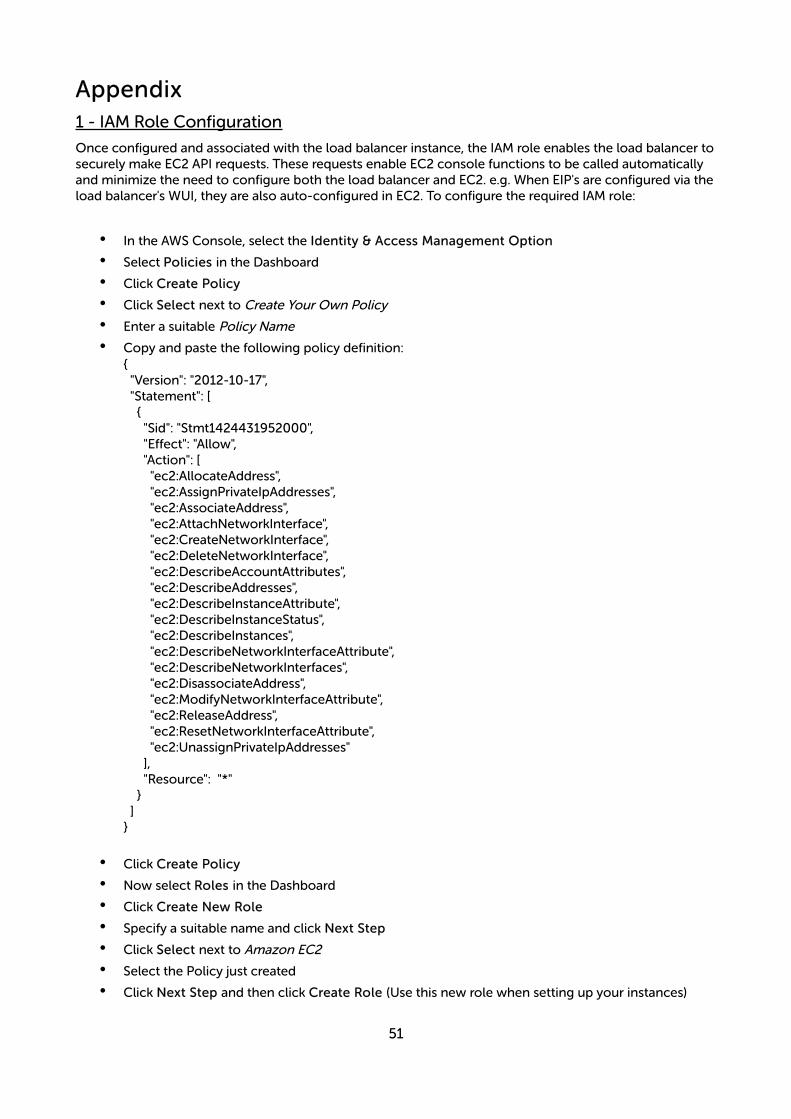
Appendix1 - IAM Role Configuration
Once configured and associated with the load balancer instance, the IAM role enables the load balancer tosecurely make EC2 API requests. These requests enable EC2 console functions to be called automatically and minimize the need to configure both the load balancer and EC2. e.g. When EIP's are configured via theload balancer's WUI, they are also auto-configured in EC2. To configure the required IAM role:
• In the AWS Console, select the Identity & Access Management Option
• Select Policies in the Dashboard
• Click Create Policy
• Click Select next to Create Your Own Policy
• Enter a suitable Policy Name
• Copy and paste the following policy definition:{ "Version": "2012-10-17", "Statement": [ { "Sid": "Stmt1424431952000", "Effect": "Allow", "Action": [ "ec2:AllocateAddress", "ec2:AssignPrivateIpAddresses", "ec2:AssociateAddress", "ec2:AttachNetworkInterface", "ec2:CreateNetworkInterface", "ec2:DeleteNetworkInterface", "ec2:DescribeAccountAttributes", "ec2:DescribeAddresses", "ec2:DescribeInstanceAttribute", "ec2:DescribeInstanceStatus", "ec2:DescribeInstances", "ec2:DescribeNetworkInterfaceAttribute", "ec2:DescribeNetworkInterfaces", "ec2:DisassociateAddress", "ec2:ModifyNetworkInterfaceAttribute", "ec2:ReleaseAddress", "ec2:ResetNetworkInterfaceAttribute", "ec2:UnassignPrivateIpAddresses" ], "Resource": "*" } ]}
• Click Create Policy
• Now select Roles in the Dashboard
• Click Create New Role
• Specify a suitable name and click Next Step
• Click Select next to Amazon EC2
• Select the Policy just created
• Click Next Step and then click Create Role (Use this new role when setting up your instances)
51
2 - Configuring the load balancer to auto add/remove auto-scaled Real Servers
If auto-scaling is used, the load balancer must be notified when EC2 instances are either launched or shutdown to ensure that the list of load balanced servers is kept up-to-date. The steps below explain what must be done to achieve this:
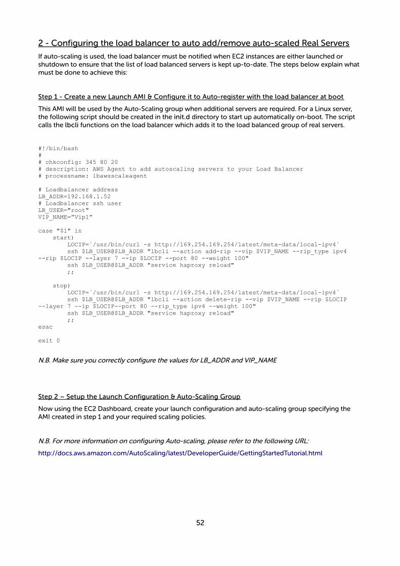
Step 1 - Create a new Launch AMI & Configure it to Auto-register with the load balancer at boot
This AMI will be used by the Auto-Scaling group when additional servers are required. For a Linux server, the following script should be created in the init.d directory to start up automatically on-boot. The script calls the lbcli functions on the load balancer which adds it to the load balanced group of real servers.
#!/bin/bash## chkconfig: 345 80 20# description: AWS Agent to add autoscaling servers to your Load Balancer# processname: lbawsscaleagent
# Loadbalancer addressLB_ADDR=192.168.1.52# Loadbalancer ssh userLB_USER="root"VIP_NAME=”Vip1”
case "$1" in start) LOCIP=`/usr/bin/curl -s http://169.254.169.254/latest/meta-data/local-ipv4` ssh $LB_USER@$LB_ADDR "lbcli --action add-rip --vip $VIP_NAME --rip_type ipv4 --rip $LOCIP --layer 7 --ip $LOCIP --port 80 --weight 100" ssh $LB_USER@$LB_ADDR "service haproxy reload" ;;
stop) LOCIP=`/usr/bin/curl -s http://169.254.169.254/latest/meta-data/local-ipv4` ssh $LB_USER@$LB_ADDR "lbcli --action delete-rip --vip $VIP_NAME --rip $LOCIP --layer 7 --ip $LOCIP--port 80 --rip_type ipv4 --weight 100" ssh $LB_USER@$LB_ADDR "service haproxy reload" ;;esac
exit 0
N.B. Make sure you correctly configure the values for LB_ADDR and VIP_NAME
Step 2 – Setup the Launch Configuration & Auto-Scaling Group
Now using the EC2 Dashboard, create your launch configuration and auto-scaling group specifying the AMI created in step 1 and your required scaling policies.
N.B. For more information on configuring Auto-scaling, please refer to the following URL:
http://docs.aws.amazon.com/AutoScaling/latest/DeveloperGuide/GettingStartedTutorial.html
52

3 - Configuring Auto-Scaling to auto deploy a new LB.org Instance on Failure
Follow this procedure to configure Auto Scaling for your Loadbalancer.org instance. Once configured, if the load balancer instance is stopped or terminated, auto-scaling will automatically start a new instance with the same settings and configuration. The steps required to set this up are shown below:
Step 1 - Deploy a Load Balancer instance
Launch and configure your Loadbalancer.org instance if not already done so.
Step 2 - Install cloud-init on your load balancer
This enables settings of the new auto scaled instance to be configured at initial launch.
• Connect via SSH – see page 18 of this guide for more details
• Login as lbuser , no password will be required
• Once logged in, enter the following command
sudo yum install cloud-init
When prompted, enter 'Y' to continue with the installation of the required packages
Step 3 - Create an image of the instance
This will be the source image when new instances are deployed.
• Right click the running instance and select: Image > Create Image
• Enter an appropriate name & description for the image – e.g. AS-LB-Recovery, LB recovery image
• Click Create Image to start the image creation process
• Image (AMI) creation should be completed in less than 1 minute, creation status can be checked under: IMAGES > AMIs
Step 4 - Configure AWS Auto Scaling
This configuration enables new instances to be automatically started when needed.
• Under AUTO SCALING select Launch Configurations
• Click the Create Auto Scaling Group button
• If no Launch Configuration exists, you'll be prompted to create one as shown below (Step 1)
53
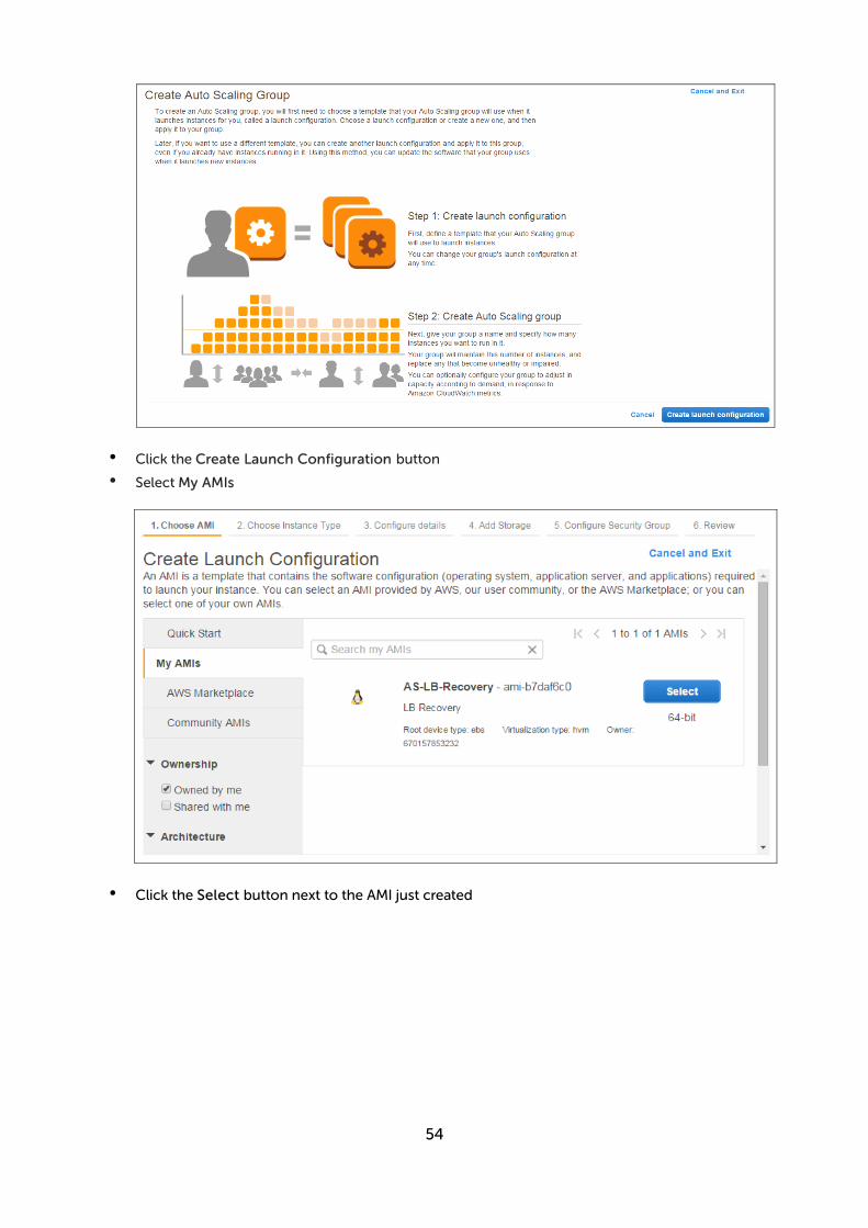
• Click the Create Launch Configuration button
• Select My AMIs
• Click the Select button next to the AMI just created
54
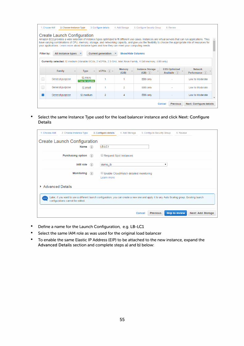
• Select the same Instance Type used for the load balancer instance and click Next: Configure Details
• Define a name for the Launch Configuration, e.g. LB-LC1
• Select the same IAM role as was used for the original load balancer
• To enable the same Elastic IP Address (EIP) to be attached to the new instance, expand the Advanced Details section and complete steps a) and b) below:
55

a) Copy/paste the following script into the User data field:
#!/bin/bash# set EIPid to the allocation ID of your Elastic IP AddressEIPid="eipalloc-3db26a58"# set LBregion to the appropriate regionLbregion="eu-west-1"export EC2_HOME=/usr/local/ec2/ec2-api-tools-1.7.1.0export JAVA_HOME=/usrexport INSTANCE_ID=$(curl -s http://169.254.169.254/latest/meta-data/instance-id)export IPV4=$(curl -s http://169.254.169.254/latest/meta-data/local-ipv4)/usr/local/ec2/ec2-api-tools-1.7.1.0/bin/ec2-associate-address -i $INSTANCE_ID --region $LBregion --allow-reassociation -a $EIPid -private-ip-address $IPV4 > /var/log/lbas.log 2>&1
NOTE: make the following changes to the above script to suit your environment:
i) change EIPid in line 3 to the allocation ID of your EIP - this can be found in the lower information pane for the EIP
ii) change LBregion in line 5 to the appropriate region
b) Change IP Address Type to Assign a public IP address to every instance
Now continue as follows:
• Click Next: Add Storage
• Click Next: Configure Security Group
• Select the same security group as used for the original load balancer instance
• Click Review
• Click Create Launch Configuration
• Configure the required key pair option
• Click Create Launch Configuration
56
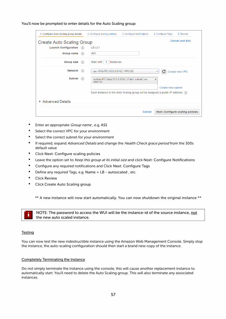
You'll now be prompted to enter details for the Auto Scaling group:
• Enter an appropriate Group name , e.g. AS1
• Select the correct VPC for your environment
• Select the correct subnet for your environment
• If required, expand Advanced Details and change the Health Check grace period from the 300s default value
• Click Next: Configure scaling policies
• Leave the option set to Keep this group at its initial size and click Next: Configure Notifications
• Configure any required notifications and Click Next: Configure Tags
• Define any required Tags, e.g. Name = LB - autoscaled , etc.
• Click Review
• Click Create Auto Scaling group
** A new instance will now start automatically. You can now shutdown the original instance **
NOTE: The password to access the WUI will be the instance-id of the source instance, not the new auto scaled instance.
Testing
You can now test the new indestructible instance using the Amazon Web Management Console. Simply stop the instance, the auto-scaling configuration should then start a brand new copy of the instance.
Completely Terminating the Instance
Do not simply terminate the instance using the console, this will cause another replacement instance to automatically start. You'll need to delete the Auto Scaling group. This will also terminate any associated instances.
57
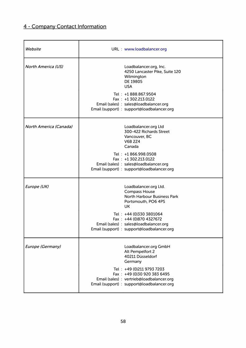
4 - Company Contact Information
Website URL : www.loadbalancer.org
North America (US) Loadbalancer.org, Inc.4250 Lancaster Pike, Suite 120WilmingtonDE 19805USA
Tel :Fax :
Email (sales) :Email (support) :
+1 888.867.9504+1 [email protected]@loadbalancer.org
North America (Canada) Loadbalancer.org Ltd300-422 Richards StreetVancouver, BCV6B 2Z4Canada
Tel :Fax :
Email (sales) :Email (support) :
+1 866.998.0508+1 [email protected]@loadbalancer.org
Europe (UK) Loadbalancer.org Ltd.Compass HouseNorth Harbour Business ParkPortsmouth, PO6 4PSUK
Tel :Fax :
Email (sales) :Email (support) :
+44 (0)330 3801064+44 (0)870 [email protected]@loadbalancer.org
Europe (Germany) Loadbalancer.org GmbHAlt Pempelfort 240211 DüsseldorfGermany
Tel :Fax :
Email (sales) :Email (support) :
+49 (0)211 9793 7203+49 (0)30 920 383 [email protected]@loadbalancer.org
58