Embed Size (px)
Citation preview
NOTE: THIS INSTRUCTION BOOKLET CONTAINS IMPORTANT SAFETY INFORMATION.
PLEASE READ AND KEEP FOR FUTURE REFERENCE.
English pg 1-42Français pg 43-47Español pg 48-52
Lot # 366086 11/05/14Purchased: __________________
Be sure to give us a ring before making any returns. 1-800-523-3987
Entertainment/Wall SystemOrchard Hills Collection | 402743
Need help? Visit Sauder.com to view video assembly tips or chat with a live rep. Prefer the phone? Call 1-800-523-3987.
Share your journey!
sauder.com
Your center of attention.
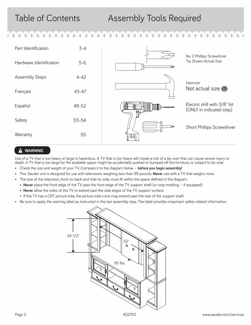
Table of Contents Assembly Tools Required
3-4
5-6
4-42
43-47
48-52
53-54
55
Part Identifi cation
Hardware Identifi cation
Assembly Steps
Français
Español
Safety
Warranty
HammerNot actual size
No. 2 Phillips ScrewdriverTip Shown Actual Size
Use of a TV that is too heavy or large is hazardous. A TV that is too heavy will create a risk of a tip-over that can cause severe injury or death. A TV that is too large for the available space might be accidentally pushed or bumped off the furniture, or subject to tip-over.• Check the size and weight of your TV. Compare it to the diagram below – before you begin assembly!• This Sauder unit is designed for use with televisions weighing less than 95 pounds. Never use with a TV that weighs more.• The size of the television, front-to-back and side-to-side, must fi t within the space defi ned in the diagram. • Never place the front edge of the TV past the front edge of the TV support shelf (or stop molding – if equipped) • Never allow the sides of the TV to extend past the side edges of the TV support surface. • If the TV has a CRT picture tube, the picture tube cone may extend past the rear of the support shelf.• Be sure to apply the warning label as instructed in the last assembly step. The label provides important safety related information.
WARNING!
95 lbs.95 lbs.
52"52"
402743 www.sauder.com/servicesPage 2
34-1/2"34-1/2"
Electric drill with 3/8" bit(ONLY in indicated step)
Short Phillips Screwdriver
Part Identifi cation
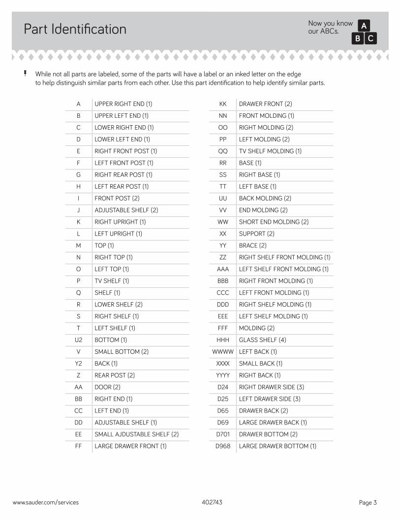
å While not all parts are labeled, some of the parts will have a label or an inked letter on the edge to help distinguish similar parts from each other. Use this part identifi cation to help identify similar parts.
A UPPER RIGHT END (1)
B UPPER LEFT END (1)
C LOWER RIGHT END (1)
D LOWER LEFT END (1)
E RIGHT FRONT POST (1)
F LEFT FRONT POST (1)
G RIGHT REAR POST (1)
H LEFT REAR POST (1)
I FRONT POST (2)
J ADJUSTABLE SHELF (2)
K RIGHT UPRIGHT (1)
L LEFT UPRIGHT (1)
M TOP (1)
N RIGHT TOP (1)
O LEFT TOP (1)
P TV SHELF (1)
Q SHELF (1)
R LOWER SHELF (2)
S RIGHT SHELF (1)
T LEFT SHELF (1)
U2 BOTTOM (1)
V SMALL BOTTOM (2)
Y2 BACK (1)
Z REAR POST (2)
AA DOOR (2)
BB RIGHT END (1)
CC LEFT END (1)
DD ADJUSTABLE SHELF (1)
EE SMALL AJDUSTABLE SHELF (2)
FF LARGE DRAWER FRONT (1)
KK DRAWER FRONT (2)
NN FRONT MOLDING (1)
OO RIGHT MOLDING (2)
PP LEFT MOLDING (2)
QQ TV SHELF MOLDING (1)
RR BASE (1)
SS RIGHT BASE (1)
TT LEFT BASE (1)
UU BACK MOLDING (2)
VV END MOLDING (2)
WW SHORT END MOLDING (2)
XX SUPPORT (2)
YY BRACE (2)
ZZ RIGHT SHELF FRONT MOLDING (1)
AAA LEFT SHELF FRONT MOLDING (1)
BBB RIGHT FRONT MOLDING (1)
CCC LEFT FRONT MOLDING (1)
DDD RIGHT SHELF MOLDING (1)
EEE LEFT SHELF MOLDING (1)
FFF MOLDING (2)
HHH GLASS SHELF (4)
WWWW LEFT BACK (1)
XXXX SMALL BACK (1)
YYYY RIGHT BACK (1)
D24 RIGHT DRAWER SIDE (3)
D25 LEFT DRAWER SIDE (3)
D65 DRAWER BACK (2)
D69 LARGE DRAWER BACK (1)
D701 DRAWER BOTTOM (2)
D968 LARGE DRAWER BOTTOM (1)
Now you knowour ABCs.
402743www.sauder.com/services Page 3
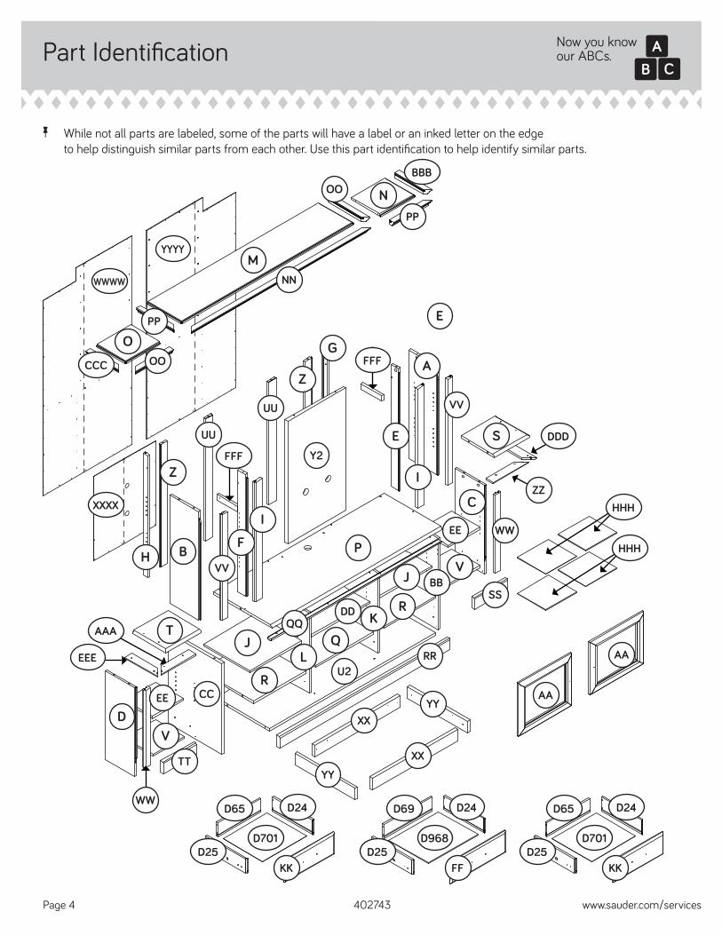
Part Identifi cation
å While not all parts are labeled, some of the parts will have a label or an inked letter on the edge to help distinguish similar parts from each other. Use this part identifi cation to help identify similar parts.
Now you knowour ABCs.
402743 www.sauder.com/servicesPage 4
A
B
C
D
E
F
G
Z
I
J
K
L
M
N
O
P
Q
R
S
T
U2
V
Y2
Z
V
J
RAA
BB
CC
DD
EE
KK
NN
OO
PP
RR
SS
TT
UU
VV
WW
XXYY
BBB
CCC
WWWW
YYYY
XXXX
D65 D24
D25D701
FF
D69 D24
D25D968
KK
D65 D24
D25D701
AA
OO
PP
AAA
EEE
DDD
ZZ
FFF
FFF
UU
H
E
I
VV
WW
EE
HHH
HHH
YYXX
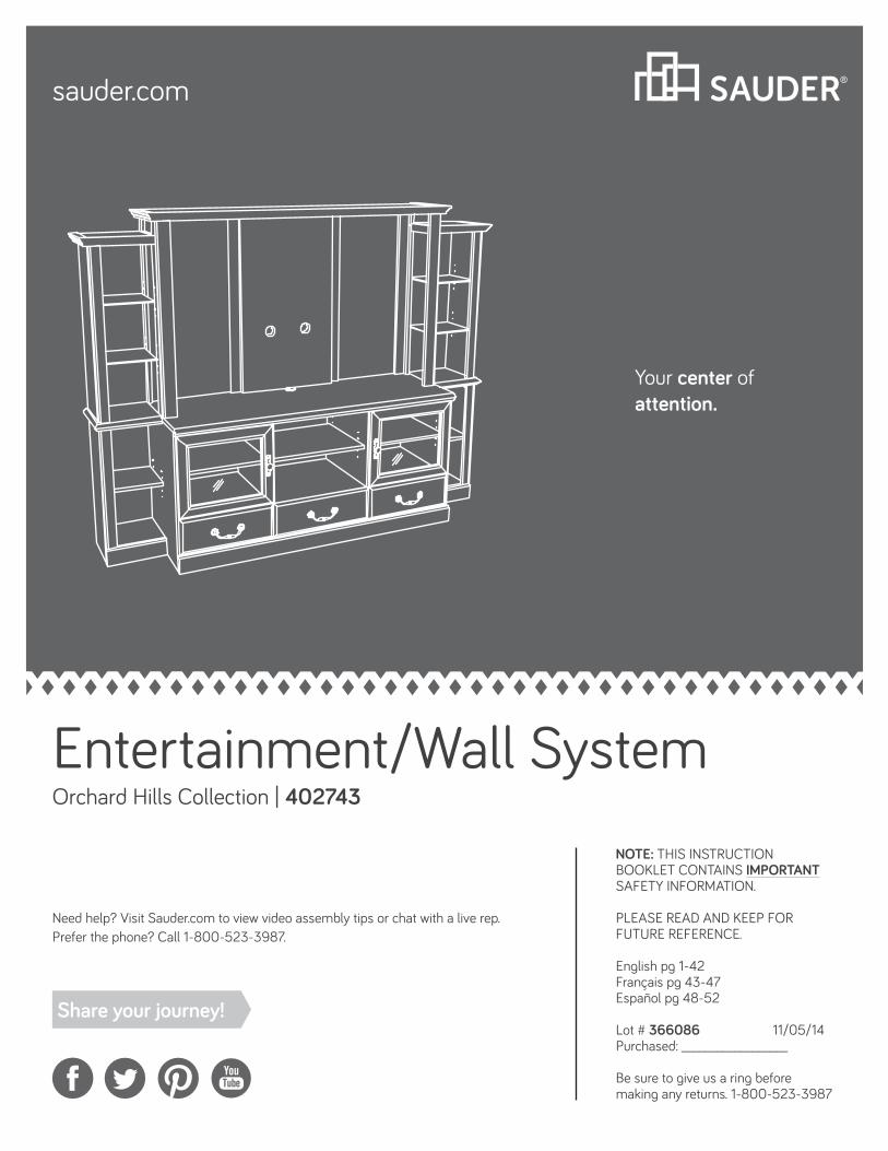
Hardware Identifi cation
402743www.sauder.com/services Page 5
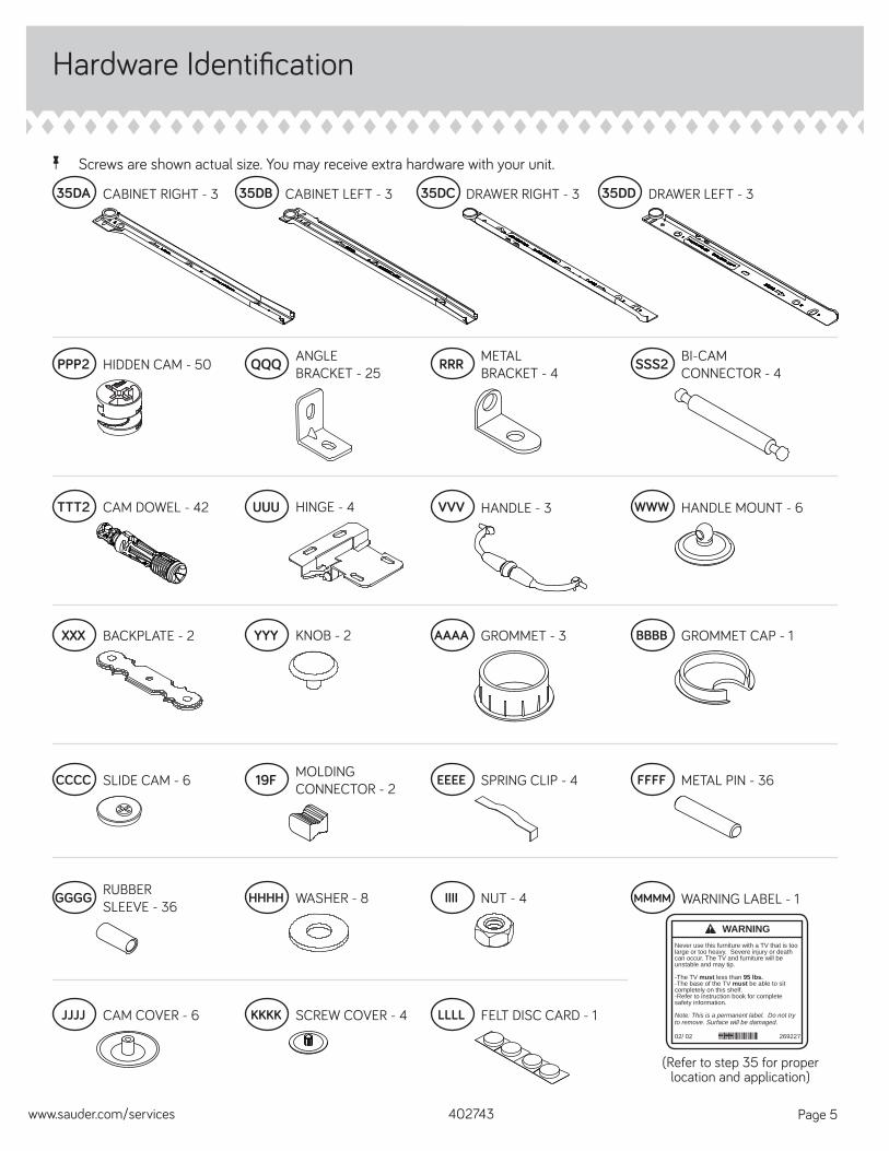
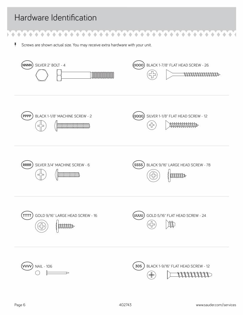
å Screws are shown actual size. You may receive extra hardware with your unit.
35DA CABINET RIGHT - 3 35DB CABINET LEFT - 3 35DC DRAWER RIGHT - 3 35DD DRAWER LEFT - 3
HIDDEN CAM - 50PPP2 METAL BRACKET - 4RRR BI-CAM
CONNECTOR - 4SSS2
CAM DOWEL - 42TTT2 HINGE - 4UUU HANDLE - 3VVV HANDLE MOUNT - 6WWW
BACKPLATE - 2XXX KNOB - 2YYY GROMMET - 3AAAA GROMMET CAP - 1BBBB
CCCC SLIDE CAM - 6 MOLDING CONNECTOR - 219F METAL PIN - 36FFFF
RUBBER SLEEVE - 36
GGGG
CAM COVER - 6JJJJ SCREW COVER - 4KKKK FELT DISC CARD - 1LLLL
(Refer to step 35 for proper location and application)
WARNING LABEL - 1MMMM
WARNINGNever use this furniture with a TV that is too large or too heavy. Severe injury or death can occur. The TV and furniture will be unstable and may tip.
-The TV must less than 95 lbs.-The base of the TV must be able to sit completely on this shelf.-Refer to instruction book for complete safety information.
Note: This is a permanent label. Do not try to remove. Surface will be damaged.
02/ 02 269227
EEEE SPRING CLIP - 4
WASHER - 8HHHH NUT - 4IIII
ANGLE BRACKET - 25QQQ
Hardware Identifi cation
å Screws are shown actual size. You may receive extra hardware with your unit.
402743 www.sauder.com/servicesPage 6
BLACK 1-7/8" FLAT HEAD SCREW - 26OOOO
BLACK 1-1/8" MACHINE SCREW - 2PPPP SILVER 1-1/8" FLAT HEAD SCREW - 12QQQQ
SILVER 3/4" MACHINE SCREW - 6RRRR BLACK 9/16" LARGE HEAD SCREW - 78SSSS
GOLD 9/16" LARGE HEAD SCREW - 16TTTT UUUU GOLD 5/16" FLAT HEAD SCREW - 24
NAIL - 106VVVV 30S BLACK 1-9/16" FLAT HEAD SCREW - 12
SILVER 2" BOLT - 4NNNN
Step 1 Look for this icon. It means a video assembly tip is available at www.sauder.com/services/tips
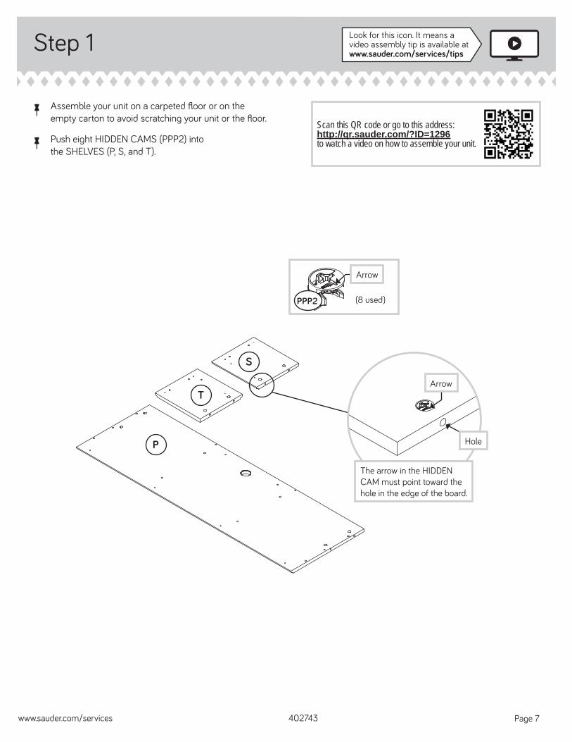
å Assemble your unit on a carpeted fl oor or on the empty carton to avoid scratching your unit or the fl oor.
å Push eight HIDDEN CAMS (PPP2) into the SHELVES (P, S, and T).
402743www.sauder.com/services Page 7
P
S
TArrow
Arrow
PPP2
The arrow in the HIDDEN CAM must point toward the hole in the edge of the board.
Hole
(8 used)
Scan this QR code or go to this address:http://qr.sauder.com/?ID=1296 to watch a video on how to assemble your unit.
Step 2
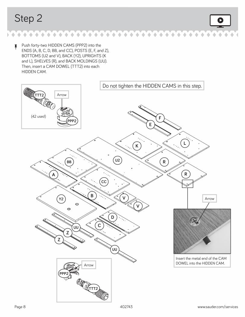
å Push forty-two HIDDEN CAMS (PPP2) into the ENDS (A, B, C, D, BB, and CC), POSTS (E, F, and Z), BOTTOMS (U2 and V), BACK (Y2), UPRIGHTS (K and L), SHELVES (R), and BACK MOLDINGS (UU). Then, insert a CAM DOWEL (TTT2) into each HIDDEN CAM.
402743 www.sauder.com/servicesPage 8
A
BB U2
CC
B V
D
CUUZ
Z
K
R
EF
L
Arrow
PPP2
TTT2
(42 used)
Arrow
PPP2
TTT2
Do not tighten the HIDDEN CAMS in this step.
Insert the metal end of the CAM DOWEL into the HIDDEN CAM.
ArrowY2
UU
V
R
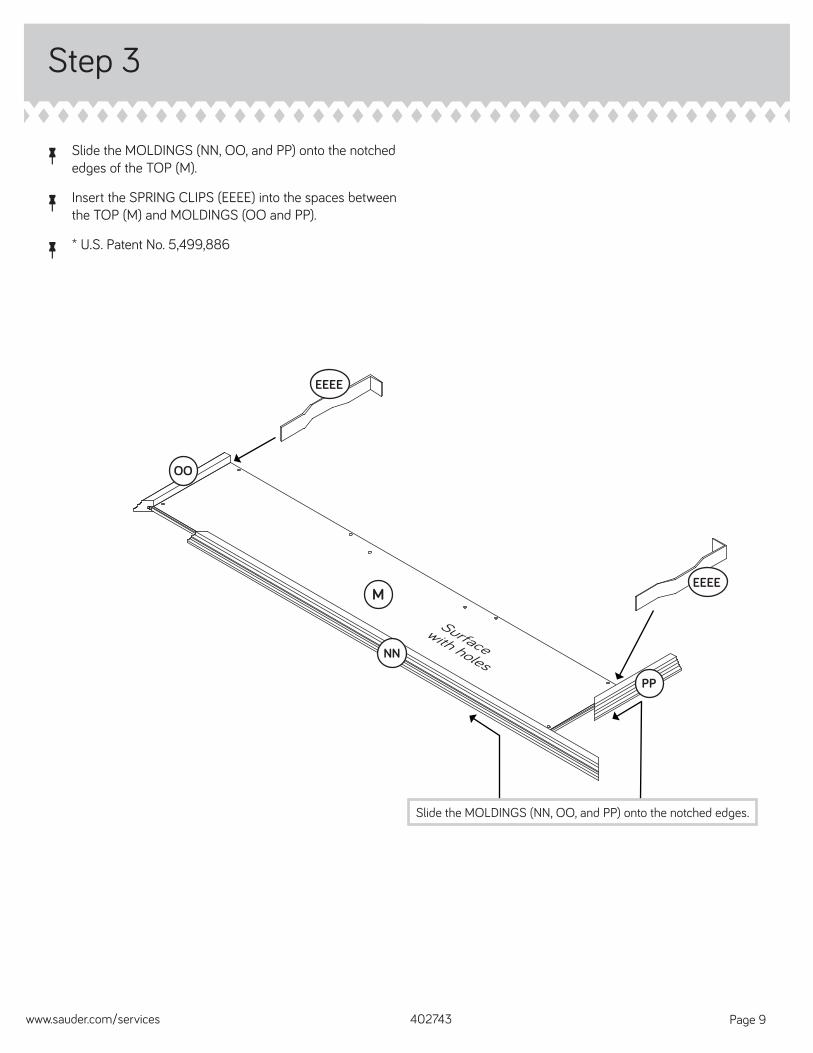
å Slide the MOLDINGS (NN, OO, and PP) onto the notched edges of the TOP (M).
å Insert the SPRING CLIPS (EEEE) into the spaces between the TOP (M) and MOLDINGS (OO and PP).
å * U.S. Patent No. 5,499,886
Step 3
402743www.sauder.com/services Page 9
M
EEEE
OO
NN
PP
EEEE
Surface with holes
Slide the MOLDINGS (NN, OO, and PP) onto the notched edges.
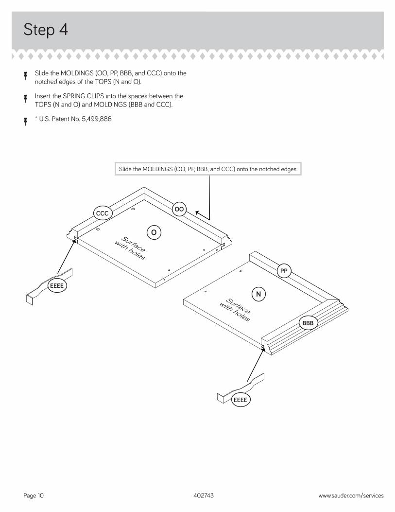
Step 4
å Slide the MOLDINGS (OO, PP, BBB, and CCC) onto the notched edges of the TOPS (N and O).
å Insert the SPRING CLIPS into the spaces between the TOPS (N and O) and MOLDINGS (BBB and CCC).
å * U.S. Patent No. 5,499,886
402743 www.sauder.com/servicesPage 10
O
EEEE
OO
EEEE
Surface with holes
Slide the MOLDINGS (OO, PP, BBB, and CCC) onto the notched edges.
CCC
N
PP
Surface with holes
BBB
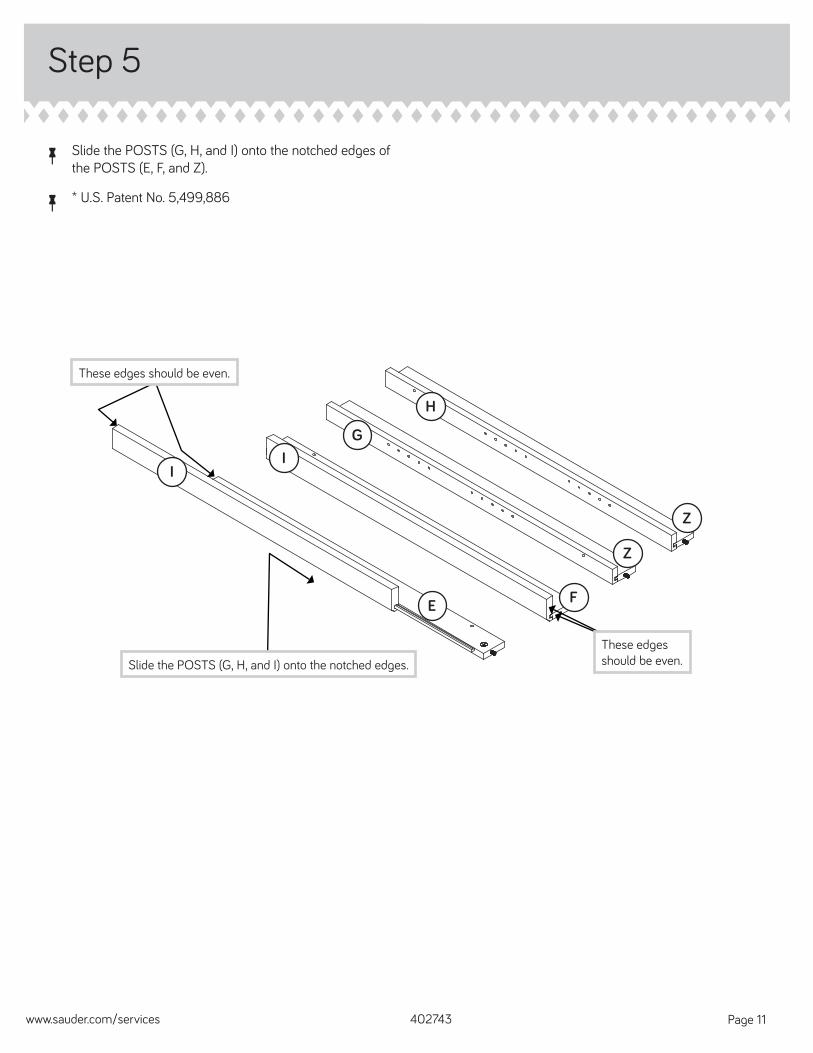
å Slide the POSTS (G, H, and I) onto the notched edges of the POSTS (E, F, and Z).
å * U.S. Patent No. 5,499,886
Step 5
402743www.sauder.com/services Page 11
E
Z
Z
F
H
GI
I
Slide the POSTS (G, H, and I) onto the notched edges.
These edges should be even.
These edges should be even.
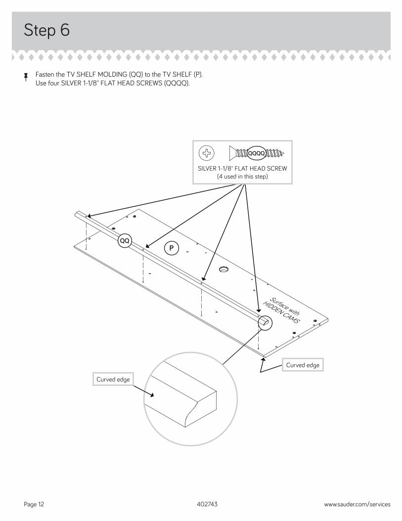
Step 6
å Fasten the TV SHELF MOLDING (QQ) to the TV SHELF (P). Use four SILVER 1-1/8" FLAT HEAD SCREWS (QQQQ).
402743 www.sauder.com/servicesPage 12
Surface with
HIDDEN CAMS
PQQ
Curved edge
Curved edge
SILVER 1-1/8" FLAT HEAD SCREW(4 used in this step)
QQQQ
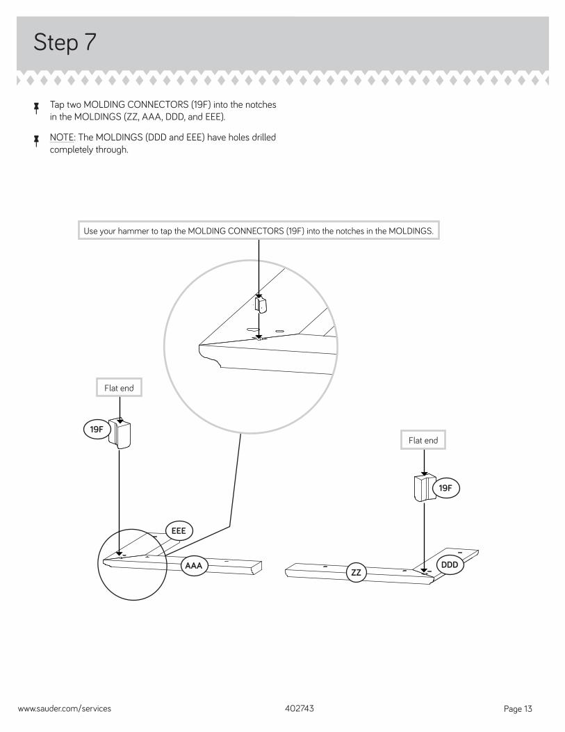
å Tap two MOLDING CONNECTORS (19F) into the notches in the MOLDINGS (ZZ, AAA, DDD, and EEE).
å NOTE: The MOLDINGS (DDD and EEE) have holes drilled completely through.
Step 7
402743www.sauder.com/services Page 13
19F
ZZ
19F
DDDAAA
EEE
Flat end
Flat end
Use your hammer to tap the MOLDING CONNECTORS (19F) into the notches in the MOLDINGS.
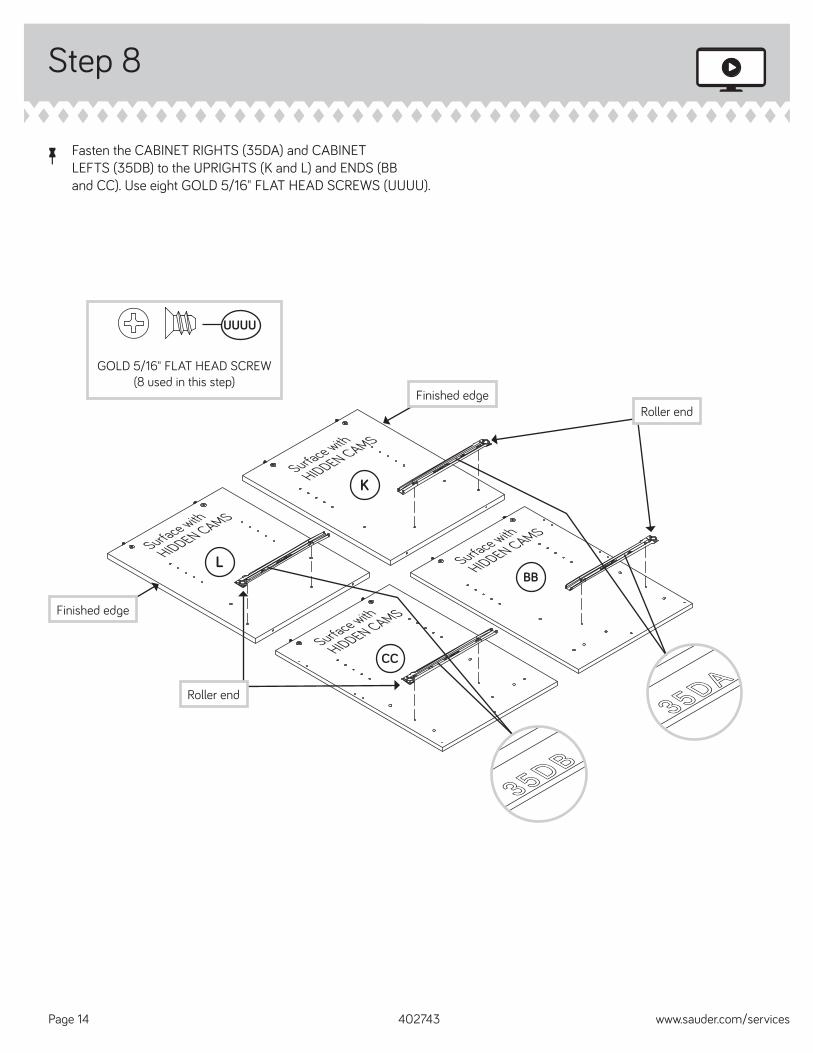
Step 8
å Fasten the CABINET RIGHTS (35DA) and CABINET LEFTS (35DB) to the UPRIGHTS (K and L) and ENDS (BB and CC). Use eight GOLD 5/16" FLAT HEAD SCREWS (UUUU).
402743 www.sauder.com/servicesPage 14
35DA35DA
35DB35DB
GOLD 5/16" FLAT HEAD SCREW(8 used in this step)
UUUU
BBSurface with
HIDDEN CAMS
CCSurface with
HIDDEN CAMS
LSurface with
HIDDEN CAMS
KSurface with
HIDDEN CAMS
Finished edge
Finished edge
Roller end
Roller end
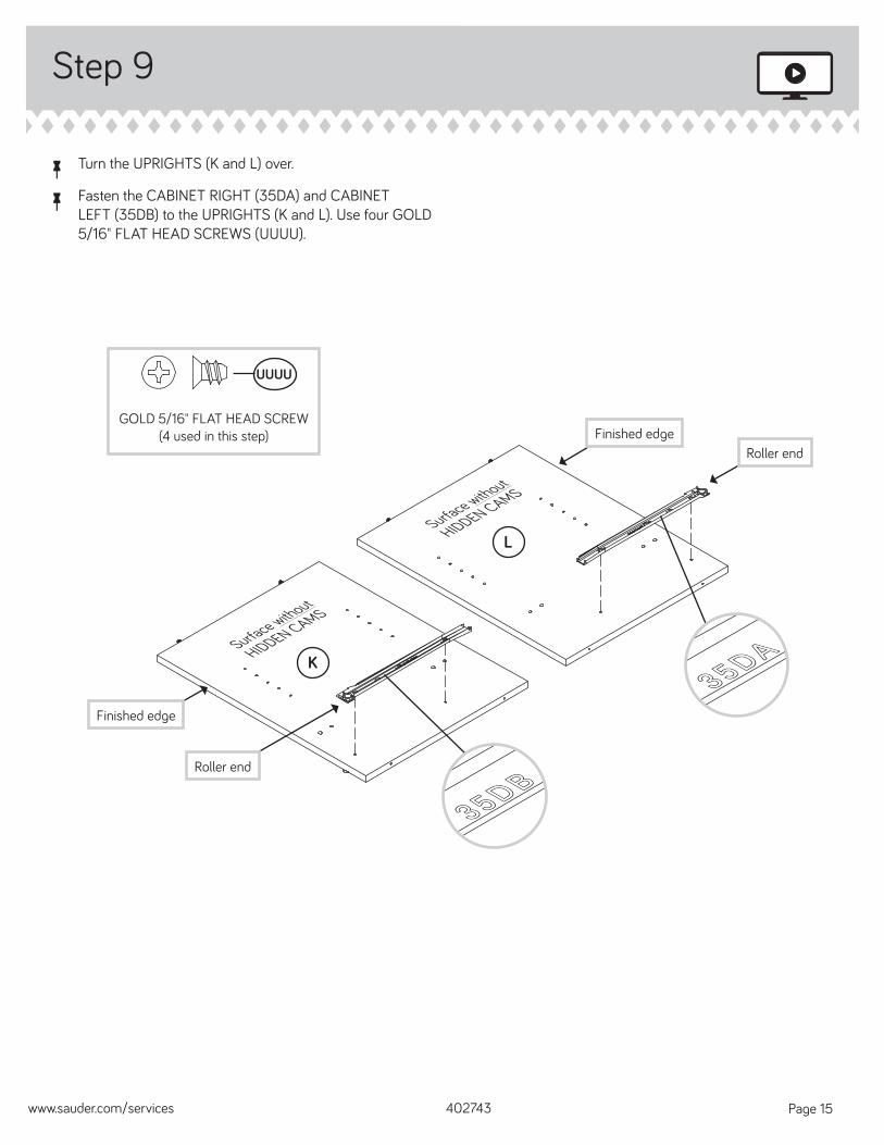
å Turn the UPRIGHTS (K and L) over.
å Fasten the CABINET RIGHT (35DA) and CABINET LEFT (35DB) to the UPRIGHTS (K and L). Use four GOLD 5/16" FLAT HEAD SCREWS (UUUU).
Step 9
402743www.sauder.com/services Page 15
35DA35DA
35DB35DB
GOLD 5/16" FLAT HEAD SCREW(4 used in this step)
UUUU
LSurface without
HIDDEN CAMS
Finished edge
Finished edge
KSurface without
HIDDEN CAMS
Roller end
Roller end
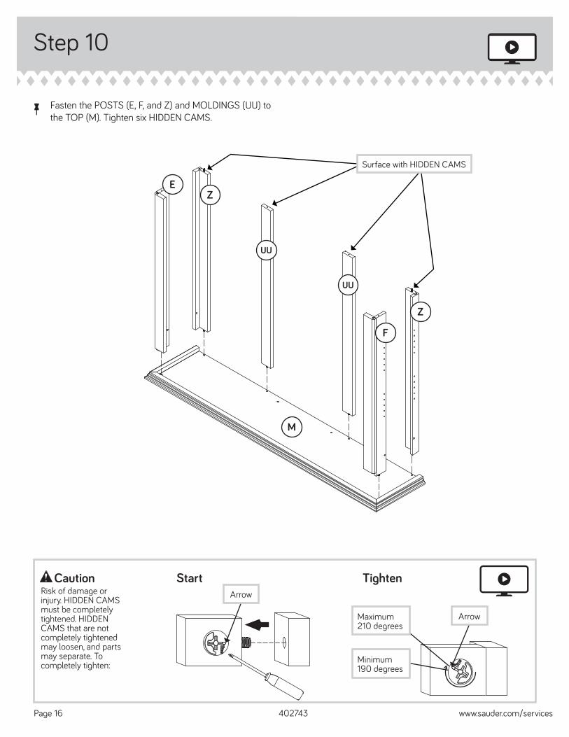
Step 10
å Fasten the POSTS (E, F, and Z) and MOLDINGS (UU) to the TOP (M). Tighten six HIDDEN CAMS.
402743 www.sauder.com/servicesPage 16
Start Tighten
Arrow
Minimum190 degrees
CautionRisk of damage or injury. HIDDEN CAMS must be completely tightened. HIDDEN CAMS that are not completely tightened may loosen, and parts may separate. To completely tighten:
Arrow
Maximum210 degrees
UU
E
UU
M
Z
F
Z
Surface with HIDDEN CAMS
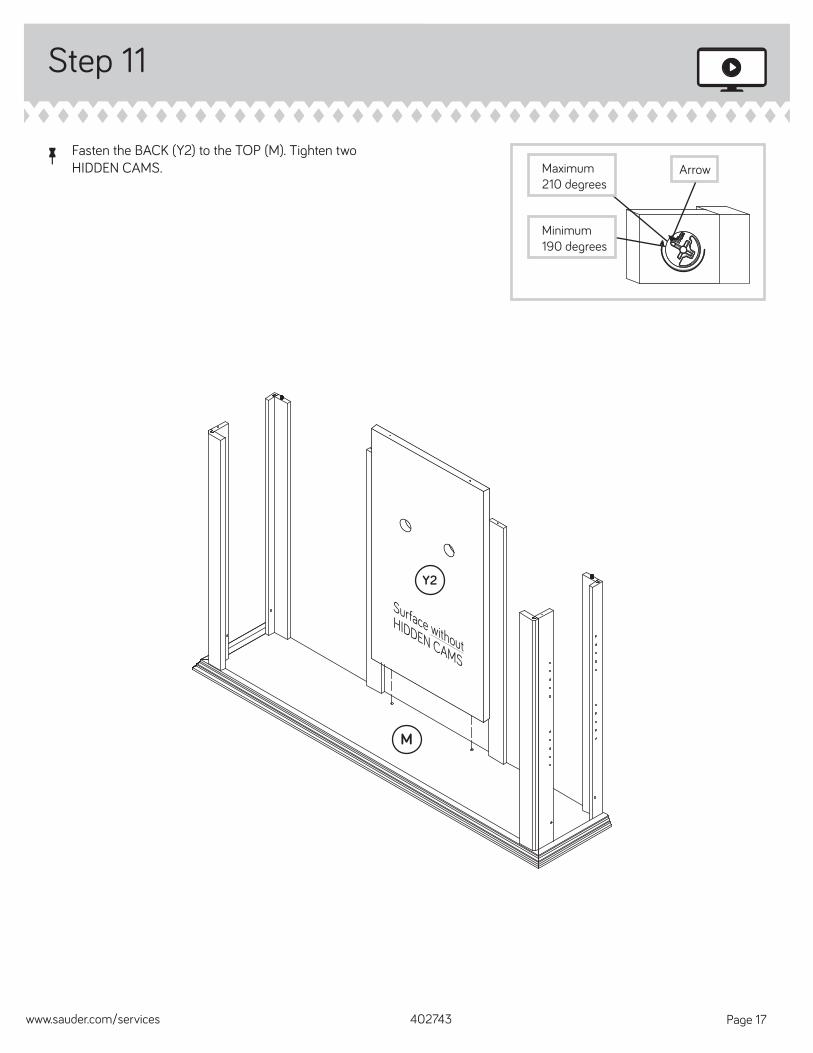
å Fasten the BACK (Y2) to the TOP (M). Tighten two HIDDEN CAMS.
Step 11
402743www.sauder.com/services Page 17
Arrow
Minimum190 degrees
Maximum210 degrees
M
Surface without
HIDDEN CAMS
Y2
Step 12
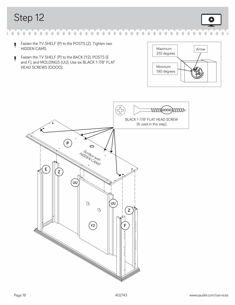
å Fasten the TV SHELF (P) to the POSTS (Z). Tighten two HIDDEN CAMS.
å Fasten the TV SHELF (P) to the BACK (Y2), POSTS (E and F), and MOLDINGS (UU). Use six BLACK 1-7/8" FLAT HEAD SCREWS (OOOO).
402743 www.sauder.com/servicesPage 18
Arrow
Minimum190 degrees
Maximum210 degrees
BLACK 1-7/8" FLAT HEAD SCREW(6 used in this step)
OOOO
UU
E
UU
P
Z
F
Z
Surface with
HIDDEN CAMS
Y2
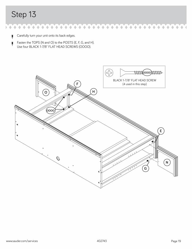
å Carefully turn your unit onto its back edges.
å Fasten the TOPS (N and O) to the POSTS (E, F, G, and H). Use four BLACK 1-7/8" FLAT HEAD SCREWS (OOOO).
Step 13
402743www.sauder.com/services Page 19
O
N
BLACK 1-7/8" FLAT HEAD SCREW(4 used in this step)
OOOO
H
F
G
E
OOOO
Step 14
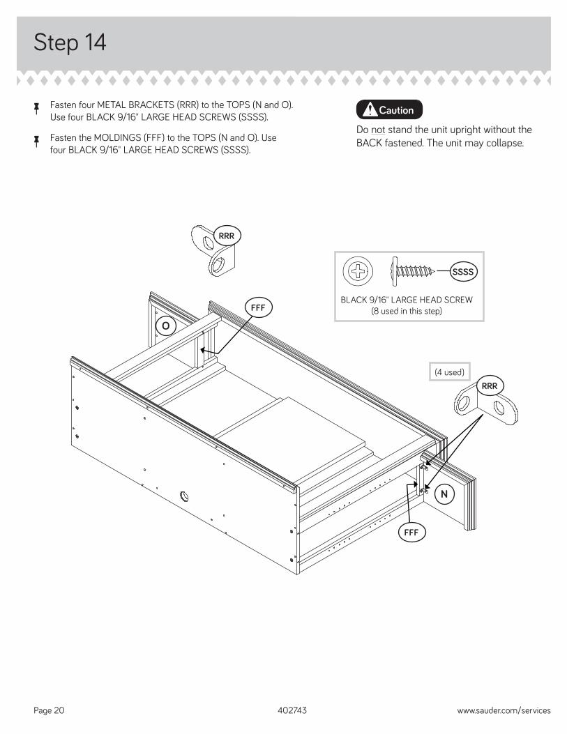
å Fasten four METAL BRACKETS (RRR) to the TOPS (N and O). Use four BLACK 9/16" LARGE HEAD SCREWS (SSSS).
å Fasten the MOLDINGS (FFF) to the TOPS (N and O). Use four BLACK 9/16" LARGE HEAD SCREWS (SSSS).
402743 www.sauder.com/servicesPage 20
O
N
BLACK 9/16" LARGE HEAD SCREW(8 used in this step)
SSSS
RRR
RRR
FFF
(4 used)
FFF
Do not stand the unit upright without the BACK fastened. The unit may collapse.
Caution
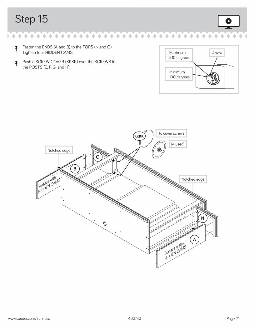
å Fasten the ENDS (A and B) to the TOPS (N and O). Tighten four HIDDEN CAMS.
å Push a SCREW COVER (KKKK) over the SCREWS in the POSTS (E, F, G, and H).
Step 15
402743www.sauder.com/services Page 21
Arrow
Minimum190 degrees
Maximum210 degrees
O
N
B
A
(4 used)
To cover screwsKKKK
Surface without
HIDDEN CAMS
Surface with
HIDDEN CAMS
Notched edge
Notched edge
Step 16
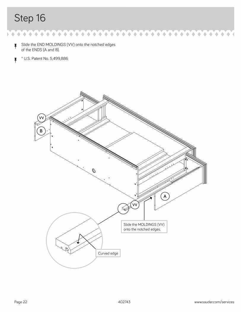
å Slide the END MOLDINGS (VV) onto the notched edges of the ENDS (A and B).
å * U.S. Patent No. 5,499,886
402743 www.sauder.com/servicesPage 22
VV
B
VV
A
Slide the MOLDINGS (VV) onto the notched edges.
Curved edge
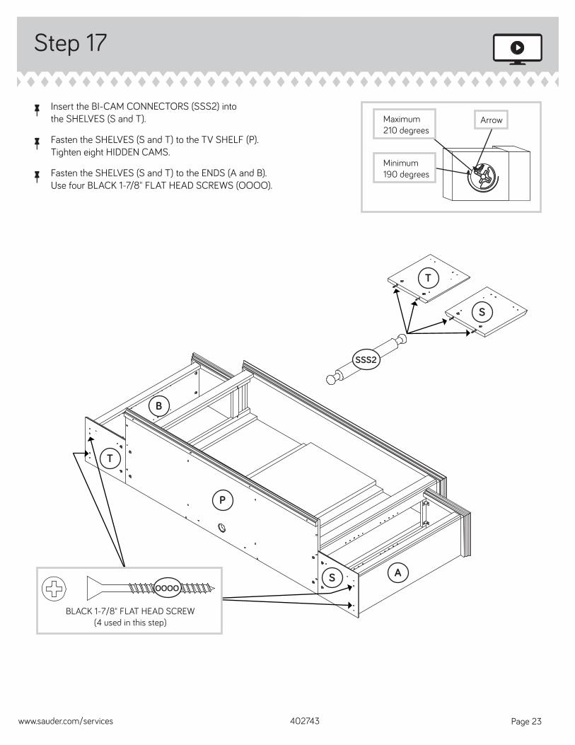
å Insert the BI-CAM CONNECTORS (SSS2) into the SHELVES (S and T).
å Fasten the SHELVES (S and T) to the TV SHELF (P). Tighten eight HIDDEN CAMS.
å Fasten the SHELVES (S and T) to the ENDS (A and B). Use four BLACK 1-7/8" FLAT HEAD SCREWS (OOOO).
Step 17
402743www.sauder.com/services Page 23
Arrow
Minimum190 degrees
Maximum210 degrees
SSS2
BLACK 1-7/8" FLAT HEAD SCREW(4 used in this step)
OOOO
T
S
A
P
B
T
S
Step 18
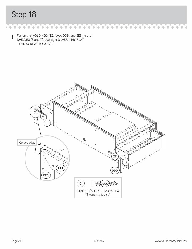
å Fasten the MOLDINGS (ZZ, AAA, DDD, and EEE) to the SHELVES (S and T). Use eight SILVER 1-1/8" FLAT HEAD SCREWS (QQQQ).
402743 www.sauder.com/servicesPage 24
Curved edge
SILVER 1-1/8" FLAT HEAD SCREW(8 used in this step)
QQQQ
ZZ
T
EEE
AAADDD
S
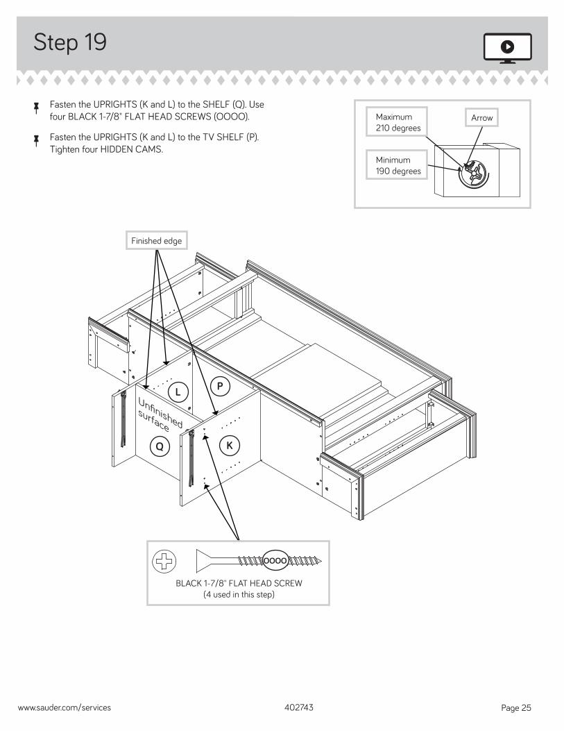
å Fasten the UPRIGHTS (K and L) to the SHELF (Q). Use four BLACK 1-7/8" FLAT HEAD SCREWS (OOOO).
å Fasten the UPRIGHTS (K and L) to the TV SHELF (P). Tighten four HIDDEN CAMS.
Step 19
402743www.sauder.com/services Page 25
Arrow
Minimum190 degrees
Maximum210 degrees
Unfi nished surface
Q
P
K
L
Finished edge
BLACK 1-7/8" FLAT HEAD SCREW(4 used in this step)
OOOO
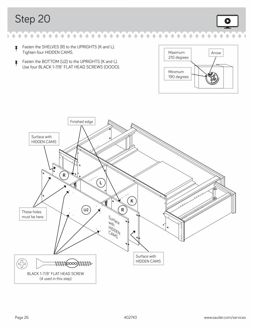
Step 20
å Fasten the SHELVES (R) to the UPRIGHTS (K and L). Tighten four HIDDEN CAMS.
å Fasten the BOTTOM (U2) to the UPRIGHTS (K and L). Use four BLACK 1-7/8" FLAT HEAD SCREWS (OOOO).
402743 www.sauder.com/servicesPage 26
Arrow
Minimum190 degrees
Maximum210 degrees
U2 R
RL
K
BLACK 1-7/8" FLAT HEAD SCREW(4 used in this step)
OOOO
Surface with HIDDEN CAMS
These holes must be here.
Surface with HIDDEN CAMS
Surface with HIDDEN CAMS
Finished edge
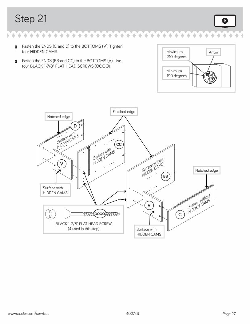
å Fasten the ENDS (C and D) to the BOTTOMS (V). Tighten four HIDDEN CAMS.
å Fasten the ENDS (BB and CC) to the BOTTOMS (V). Use four BLACK 1-7/8" FLAT HEAD SCREWS (OOOO).
Step 21
402743www.sauder.com/services Page 27
Arrow
Minimum190 degrees
Maximum210 degrees
Finished edge
Notched edge
CC
V
Notched edge
BB
C
V
D
Surface with
HIDDEN CAMS
Surface without
HIDDEN CAMS
Surface with
HIDDEN CAMS
Surface without
HIDDEN CAMS
Surface with HIDDEN CAMS
Surface with HIDDEN CAMS
BLACK 1-7/8" FLAT HEAD SCREW(4 used in this step)
OOOO
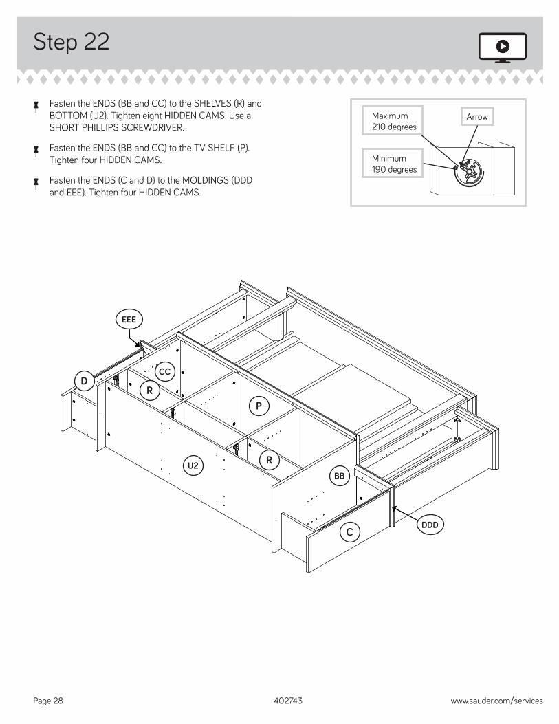
Step 22
å Fasten the ENDS (BB and CC) to the SHELVES (R) and BOTTOM (U2). Tighten eight HIDDEN CAMS. Use a SHORT PHILLIPS SCREWDRIVER.
å Fasten the ENDS (BB and CC) to the TV SHELF (P). Tighten four HIDDEN CAMS.
å Fasten the ENDS (C and D) to the MOLDINGS (DDD and EEE). Tighten four HIDDEN CAMS.
402743 www.sauder.com/servicesPage 28
Arrow
Minimum190 degrees
Maximum210 degrees
CCD
BB
C
P
R
R
U2
EEE
DDD
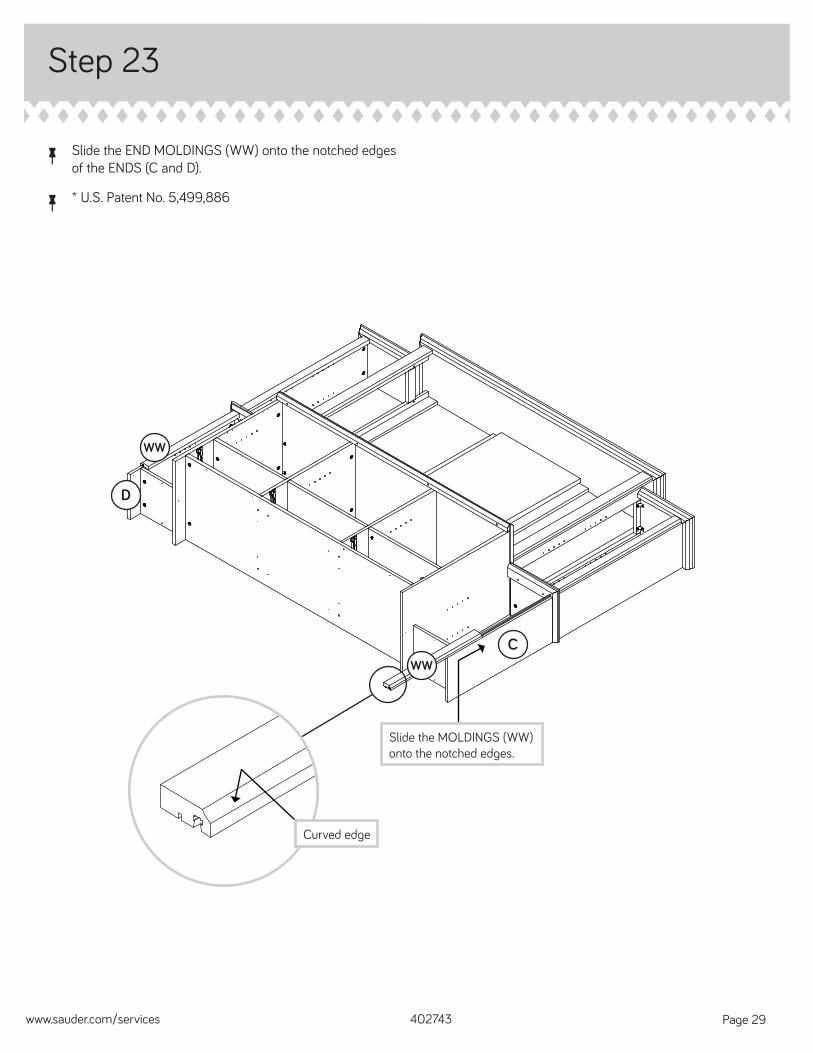
å Slide the END MOLDINGS (WW) onto the notched edges of the ENDS (C and D).
å * U.S. Patent No. 5,499,886
Step 23
402743www.sauder.com/services Page 29
WW
D
C
WW
Slide the MOLDINGS (WW) onto the notched edges.
Curved edge

Step 24
å Fasten thirteen METAL BRACKETS (QQQ) to the ENDS (C, D, BB, and CC) and BOTTOMS (U2 and V). Use thirteen BLACK 9/16" LARGE HEAD SCREWS (SSSS).
402743 www.sauder.com/servicesPage 30
BLACK 9/16" LARGE HEAD SCREW(13 used in this step)
SSSS
(13 used)
CC
D
BB
CV
U2
V
QQQ
QQQ
QQQ
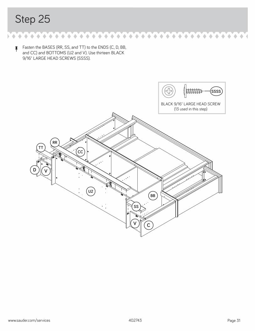
å Fasten the BASES (RR, SS, and TT) to the ENDS (C, D, BB, and CC) and BOTTOMS (U2 and V). Use thirteen BLACK 9/16" LARGE HEAD SCREWS (SSSS).
Step 25
402743www.sauder.com/services Page 31
U2
BLACK 9/16" LARGE HEAD SCREW(13 used in this step)
SSSS
SS
V
V
BB
CC
RRTT
C
D
Step 26
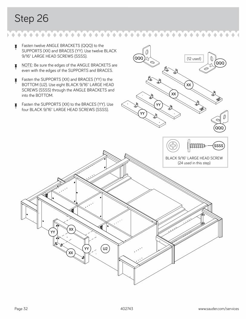
å Fasten twelve ANGLE BRACKETS (QQQ) to the SUPPORTS (XX) and BRACES (YY). Use twelve BLACK 9/16" LARGE HEAD SCREWS (SSSS).
å NOTE: Be sure the edges of the ANGLE BRACKETS are even with the edges of the SUPPORTS and BRACES.
å Fasten the SUPPORTS (XX) and BRACES (YY) to the BOTTOM (U2). Use eight BLACK 9/16" LARGE HEAD SCREWS (SSSS) through the ANGLE BRACKETS and into the BOTTOM.
å Fasten the SUPPORTS (XX) to the BRACES (YY). Use four BLACK 9/16" LARGE HEAD SCREWS (SSSS).
402743 www.sauder.com/servicesPage 32
BLACK 9/16" LARGE HEAD SCREW(24 used in this step)
SSSS
U2
YY
YY
XX
XX
YY
YY
XX
XX
(12 used)QQQQQQ
QQQ
Step Step 27
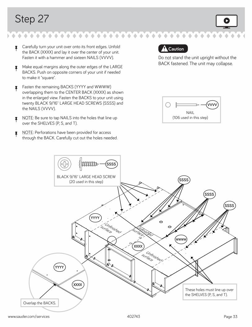
å Carefully turn your unit over onto its front edges. Unfold the BACK (XXXX) and lay it over the center of your unit. Fasten it with a hammer and sixteen NAILS (VVVV).
å Make equal margins along the outer edges of the LARGE BACKS. Push on opposite corners of your unit if needed to make it "square".
å Fasten the remaining BACKS (YYYY and WWWW) overlapping them to the CENTER BACK (XXXX) as shown in the enlarged view. Fasten the BACKS to your unit using twenty BLACK 9/16" LARGE HEAD SCREWS (SSSS) and the NAILS (VVVV).
å NOTE: Be sure to tap NAILS into the holes that line up over the SHELVES (P, S, and T).
å NOTE: Perforations have been provided for access through the BACK. Carefully cut out the holes needed.
402743www.sauder.com/services Page 33
Do not stand the unit upright without the BACK fastened. The unit may collapse.
Caution
Unfi nished surface
NAIL(106 used in this step)
VVVV
YYYY
XXXX
WWWW
Unfi nished surface
Unfi nished surface
YYYY
XXXX
Overlap the BACKS.
BLACK 9/16" LARGE HEAD SCREW(20 used in this step)
SSSS
SSSS
SSSS
SSSS
These holes must line up over the SHELVES (P, S, and T).
Step
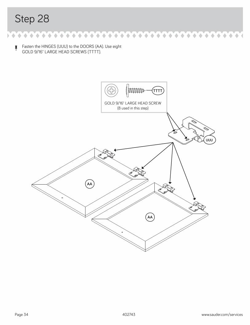
å Fasten the HINGES (UUU) to the DOORS (AA). Use eight GOLD 9/16" LARGE HEAD SCREWS (TTTT).
Step 28
402743 www.sauder.com/servicesPage 34
UUU
AA
AA
GOLD 9/16" LARGE HEAD SCREW(8 used in this step)
TTTT
Step
402743www.sauder.com/services Page 35
Step 29
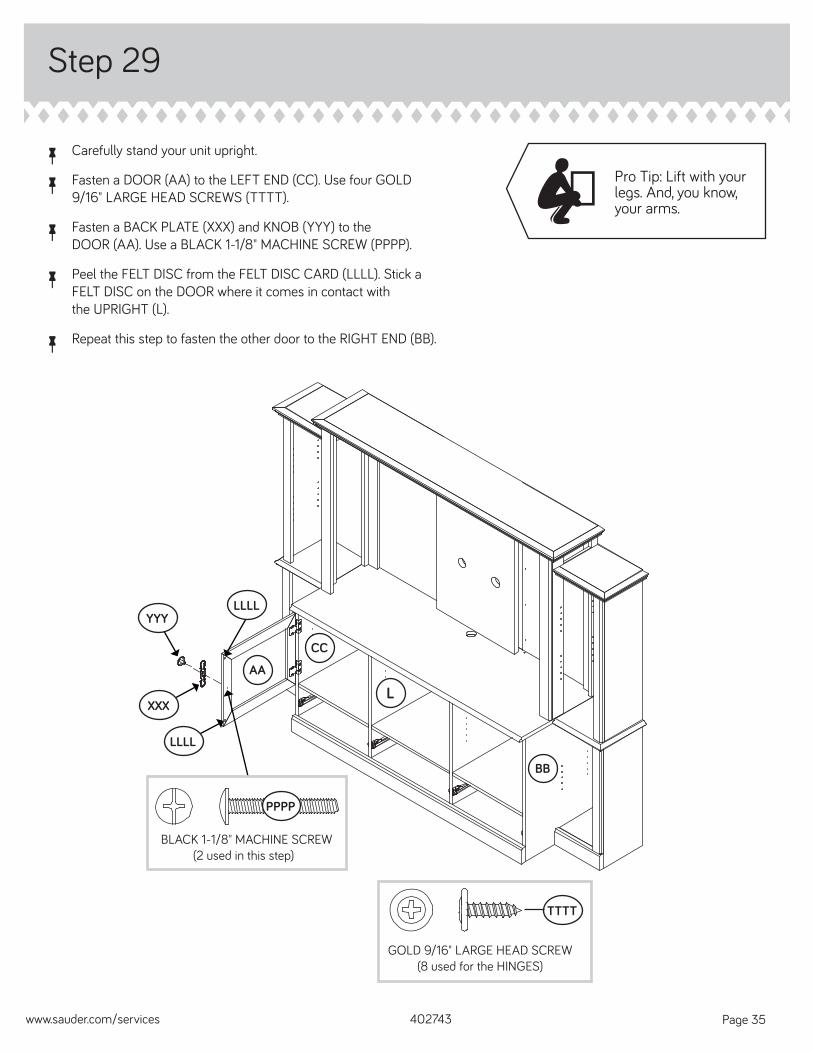
å Carefully stand your unit upright.
å Fasten a DOOR (AA) to the LEFT END (CC). Use four GOLD 9/16" LARGE HEAD SCREWS (TTTT).
å Fasten a BACK PLATE (XXX) and KNOB (YYY) to the DOOR (AA). Use a BLACK 1-1/8" MACHINE SCREW (PPPP).
å Peel the FELT DISC from the FELT DISC CARD (LLLL). Stick a FELT DISC on the DOOR where it comes in contact with the UPRIGHT (L).
å Repeat this step to fasten the other door to the RIGHT END (BB).
AA
GOLD 9/16" LARGE HEAD SCREW(8 used for the HINGES)
TTTT
L
Pro Tip: Lift with your legs. And, you know, your arms.
BB
CC
LLLL
XXX
YYY
LLLL
BLACK 1-1/8" MACHINE SCREW(2 used in this step)
PPPP
Step Step 30
402743 www.sauder.com/servicesPage 36
VIEW THE T-LOCK BOX VIDEO
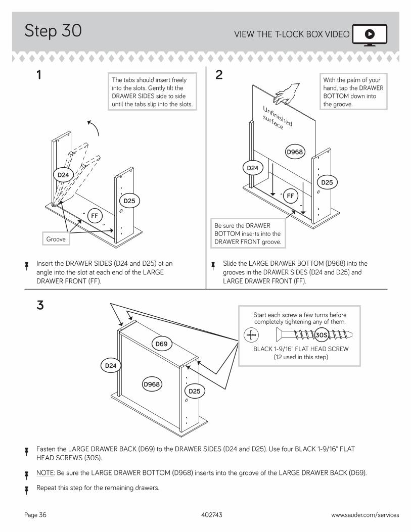
å Fasten the LARGE DRAWER BACK (D69) to the DRAWER SIDES (D24 and D25). Use four BLACK 1-9/16" FLAT HEAD SCREWS (30S).
å NOTE: Be sure the LARGE DRAWER BOTTOM (D968) inserts into the groove of the LARGE DRAWER BACK (D69).
å Repeat this step for the remaining drawers.
1 2
3
å Insert the DRAWER SIDES (D24 and D25) at an angle into the slot at each end of the LARGE DRAWER FRONT (FF).
å Slide the LARGE DRAWER BOTTOM (D968) into the grooves in the DRAWER SIDES (D24 and D25) and LARGE DRAWER FRONT (FF).
The tabs should insert freely into the slots. Gently tilt the DRAWER SIDES side to side until the tabs slip into the slots.
Groove
Start each screw a few turns before completely tightening any of them.
BLACK 1-9/16" FLAT HEAD SCREW(12 used in this step)
30S
Be sure the DRAWER BOTTOM inserts into the DRAWER FRONT groove.
D24
D25
D968
D968
D24
D25
D69
D25
FF
FF
Unfi nished surface
With the palm of your hand, tap the DRAWER BOTTOM down into the groove.
D24
Step
402743www.sauder.com/services Page 37
Step 31
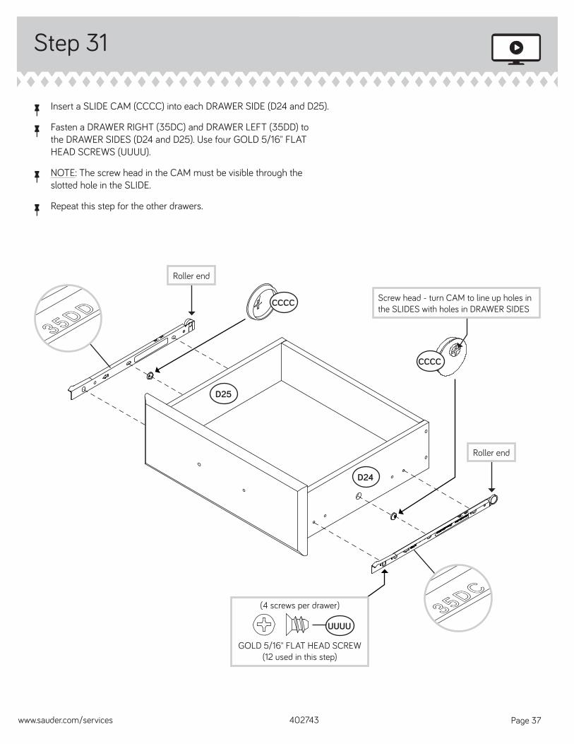
å Insert a SLIDE CAM (CCCC) into each DRAWER SIDE (D24 and D25).
å Fasten a DRAWER RIGHT (35DC) and DRAWER LEFT (35DD) to the DRAWER SIDES (D24 and D25). Use four GOLD 5/16" FLAT HEAD SCREWS (UUUU).
å NOTE: The screw head in the CAM must be visible through the slotted hole in the SLIDE.
å Repeat this step for the other drawers.
35DD35DD
35DC35DC
Roller end
Screw head - turn CAM to line up holes in the SLIDES with holes in DRAWER SIDES
CCCC
CCCC
D25
D24
Roller end
GOLD 5/16" FLAT HEAD SCREW(12 used in this step)
UUUU
(4 screws per drawer)
Step
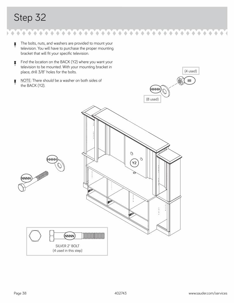
å The bolts, nuts, and washers are provided to mount your television. You will have to purchase the proper mounting bracket that will fi t your specifi c television.
å Find the location on the BACK (Y2) where you want your television to be mounted. With your mounting bracket in place, drill 3/8" holes for the bolts.
å NOTE: There should be a washer on both sides of the BACK (Y2).
Step 32
402743 www.sauder.com/servicesPage 38
SILVER 2" BOLT(4 used in this step)
NNNN
NNNN
HHHH
HHHH
IIII
(4 used)
(8 used)
Y2
Step
402743www.sauder.com/services Page 39
Step 33
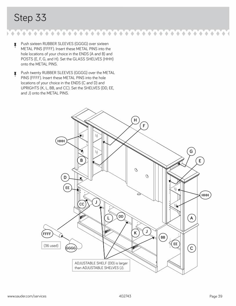
å Push sixteen RUBBER SLEEVES (GGGG) over sixteen METAL PINS (FFFF). Insert these METAL PINS into the hole locations of your choice in the ENDS (A and B) and POSTS (E, F, G, and H). Set the GLASS SHELVES (HHH) onto the METAL PINS.
å Push twenty RUBBER SLEEVES (GGGG) over the METAL PINS (FFFF). Insert these METAL PINS into the hole locations of your choice in the ENDS (C and D) and UPRIGHTS (K, L, BB, and CC). Set the SHELVES (DD, EE, and J) onto the METAL PINS.
A
CC
C
B
L
KBB
EE
G
J
DD
J
GGGG
FFFF
HHH
HHH
ADJUSTABLE SHELF (DD) is larger than ADJUSTABLE SHELVES (J).
HF
E
EE
D
(36 used)
Step
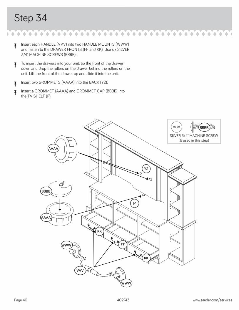
å Insert each HANDLE (VVV) into two HANDLE MOUNTS (WWW) and fasten to the DRAWER FRONTS (FF and KK). Use six SILVER 3/4" MACHINE SCREWS (RRRR).
å To insert the drawers into your unit, tip the front of the drawer down and drop the rollers on the drawer behind the rollers on the unit. Lift the front of the drawer up and slide it into the unit.
å Insert two GROMMETS (AAAA) into the BACK (Y2).
å Insert a GROMMET (AAAA) and GROMMET CAP (BBBB) into the TV SHELF (P).
Step 34
WWW
WWW
VVV
SILVER 3/4" MACHINE SCREW(6 used in this step)
RRRR
KK
KK
FF
BBBB
AAAA
P
Y2
402743 www.sauder.com/servicesPage 40
AAAA
Step 35
402743www.sauder.com/services Page 41
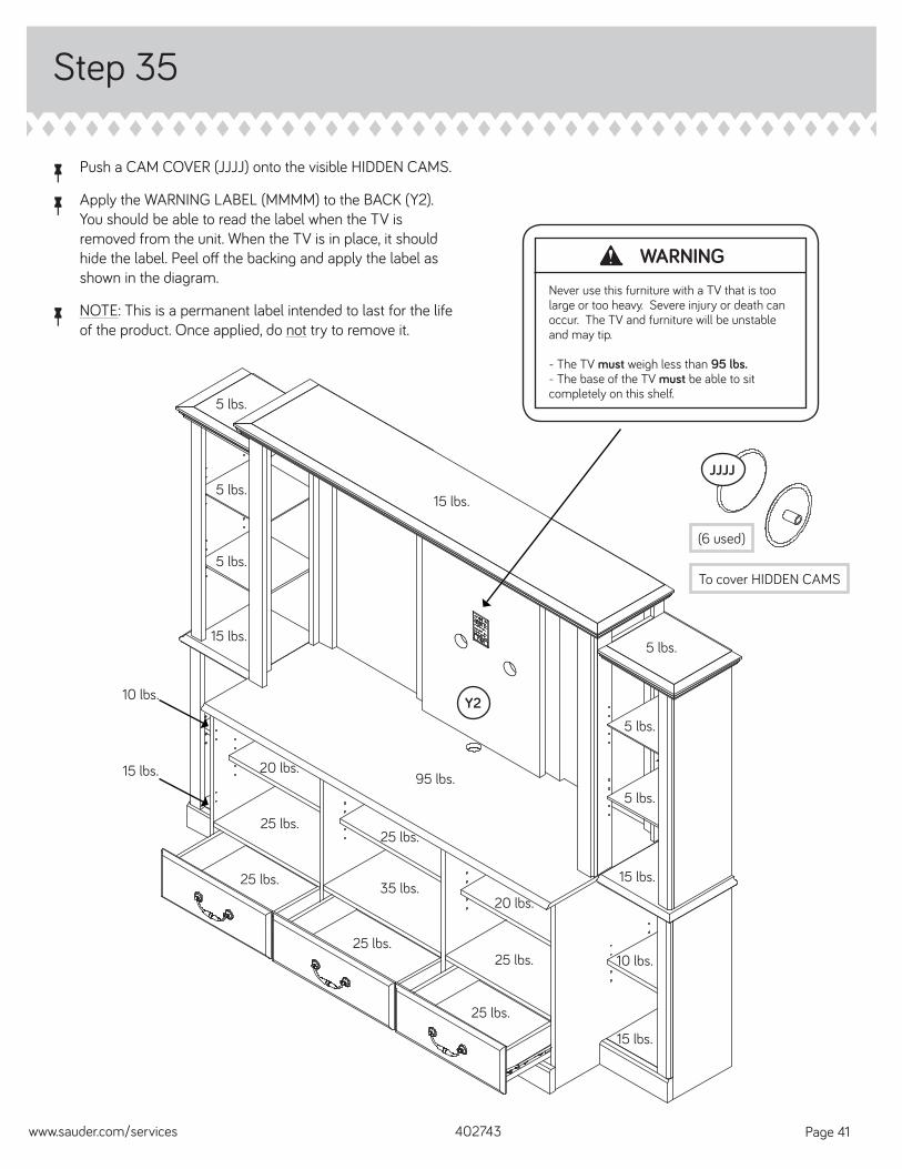
å Push a CAM COVER (JJJJ) onto the visible HIDDEN CAMS.
å Apply the WARNING LABEL (MMMM) to the BACK (Y2). You should be able to read the label when the TV is removed from the unit. When the TV is in place, it should hide the label. Peel off the backing and apply the label as shown in the diagram.
å NOTE: This is a permanent label intended to last for the life of the product. Once applied, do not try to remove it.
WARNINGNever use this furniture with a TV that is too large or too heavy. Severe injury or death can occur. The TV and furniture will be unstable and may tip.
- The TV must weigh less than 95 lbs.- The base of the TV must be able to sit completely on this shelf.
5 lbs.
5 lbs.
5 lbs.
5 lbs.
5 lbs.
5 lbs.
15 lbs.
95 lbs.20 lbs.
25 lbs.
20 lbs.
10 lbs.
15 lbs.
25 lbs.
25 lbs.
25 lbs. 35 lbs.
25 lbs.
25 lbs.
15 lbs.
15 lbs.
10 lbs.
15 lbs.
(6 used)
To cover HIDDEN CAMS
JJJJ
Y2
Step 36
402743 www.sauder.com/servicesPage 42
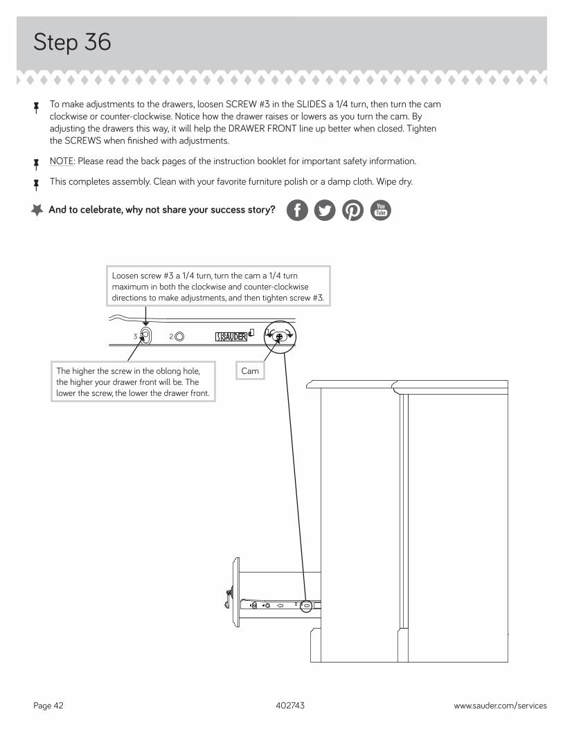
å To make adjustments to the drawers, loosen SCREW #3 in the SLIDES a 1/4 turn, then turn the cam clockwise or counter-clockwise. Notice how the drawer raises or lowers as you turn the cam. By adjusting the drawers this way, it will help the DRAWER FRONT line up better when closed. Tighten the SCREWS when fi nished with adjustments.
å NOTE: Please read the back pages of the instruction booklet for important safety information.
å This completes assembly. Clean with your favorite furniture polish or a damp cloth. Wipe dry.
3 2
Loosen screw #3 a 1/4 turn, turn the cam a 1/4 turn maximum in both the clockwise and counter-clockwise directions to make adjustments, and then tighten screw #3.
The higher the screw in the oblong hole, the higher your drawer front will be. The lower the screw, the lower the drawer front.
Cam
And to celebrate, why not share your success story?
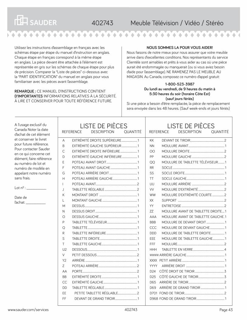
A l’usage exclusif du Canada Noter la date d’achat de cet élément et conserver le livret pour future référence. Pour contacter Sauder en ce qui concerne cet élément, faire référence au numéro de lot et numéro de modèle en appelant notre numéro sans frais.
Lot nº : ____________
Date del’achat: ____________
LISTE DE PIÈCESREFERENCE DESCRIPTION QUANTITÉ
LISTE DE PIÈCESREFERENCE DESCRIPTION QUANTITÉ
NOUS SOMMES LA POUR VOUS AIDER!Nous faisons de notre mieux pour nous assurer que votre meuble arrive dans d’excellentes conditions. Nos représentants du service Clientèle sont aimables et prêts à vous aider au cas où une pièce aurait été endommagée ou manquerait (ou si vous aviez besoin d’aide pour l’assemblage). NE RAMENEZ PAS LE MEUBLE AU MAGASIN. Au Canada, composez ce numéro d’appel gratuit:
1-800-523-3987Du lundi au vendredi, de 9 heures du matin à
5:30 heures du soir (horaire Côte Est)(sauf jours fériés)
Si une pièce a besoin d’être remplacée, la pièce de remplacement sera envoyée dans les 48 heures. (Sauf week-ends et jours fériés)
Utilisez les instructions d’assemblage en français avec les schémas étape par étape du manuel d’instruction en anglais. Chaque étape en français correspond à la même étape en anglais. La pièce devant être attachée à l’élément est représentée en gris sur les schémas de chaque étape pour plus de précision. Comparer la “Liste de pièces” ci-dessous avec la “PART IDENTIFICATION” du manuel en anglais pour vous familiariser avec les pièces avant l’assemblage.
REMARQUE : CE MANUEL D’INSTRUCTIONS CONTIENT D’IMPORTANTES INFORMATIONS RELATIVES À LA SÉCURITÉ. À LIRE ET CONSERVER POUR TOUTE RÉFÉRENCE FUTURE.
Meuble Télévision / Vidéo / Stéréo402743
KK DEVANT DE TIROIR.......................................................... 2NN MOULURE AVANT.............................................................. 1OO MOULURE DROITE .......................................................... 2PP MOULURE GAUCHE ....................................................... 2QQ MOULURE DE TABLETTE TÉLÉVISEUR ........... 1RR SOCLE ......................................................................................... 1SS SOCLE DROITE .................................................................... 1TT SOCLE GAUCHE ................................................................. 1UU MOULURE ARRIÈRE ....................................................... 2VV MOULURE D’EXTRÉMITÉ ............................................ 2WW MOULURE D’EXTRÉMITÉ COURTE .................... 2XX SUPPORT ............................................................................... 2YY ENTRETOISE ......................................................................... 2ZZ MOULURE AVANT DE TABLETTE DROITE .... 1AAA MOULURE AVANT DE TABLETTE GAUCHE . 1BBB MOULURE DE DEVANT DROIT ............................... 1CCC MOULURE DE DEVANT GAUCHE ......................... 1DDD MOULURE DE TABLETTE DROITE ....................... 1EEE MOULURE DE TABLETTE GAUCHE .................... 1FFF MOULURE ................................................................................ 2HHH TABLETTE EN VERRE .....................................................4WWWW ARRIÈRE GAUCHE ................................................................. 1XXXX PETIT ARRIÈRE ......................................................................... 1YYYY ARRIÈRE DROIT .................................................................. 1D24 CÔTÉ DROIT DE TIROIR ..................................................3D25 CÔTÉ GAUCHE DE TIROIR ............................................3D65 ARRIÈRE DE TIROIR ............................................................. 2D69 ARRIÈRE DE GRAND TIROIR ......................................... 1D701 FOND DE TIROIR .................................................................... 2D968 FOND DE GRAND TIROIR ................................................ 1
A EXTRÉMITÉ DROITE SUPÉRIEURE ........................... 1B EXTRÉMITÉ GAUCHE SUPÉRIEUR ........................... 1C EXTRÉMITÉ DROITE INFÉRIEURE ............................. 1D EXTRÉMITÉ GAUCHE INFÉRIEURE .......................... 1E POTEAU AVANT DROIT ..................................................... 1F POTEAU AVANT GAUCHE .............................................. 1G POTEAU ARRIÈRE DROIT ................................................ 1H POTEAU ARRIÈRE GAUCHE .......................................... 1I POTEAU AVANT ...................................................................... 2J TABLETTE RÉGLABLE ....................................................... 2K MONTANT DROIT ................................................................. 1L MONTANT GAUCHE ............................................................ 1M DESSUS .......................................................................................... 1N DESSUS DROIT ........................................................................ 1O DESSUS GAUCHE .................................................................. 1P TABLETTE TÉLÉVISEUR .................................................... 1Q TABLETTE ..................................................................................... 1R TABLETTE INFÉRIEURE ..................................................... 1S TABLETTE DROITE ................................................................ 1T TABLETTE GAUCHE ............................................................. 1U2 DESSOUS ...................................................................................... 1V PETIT DESSOUS .................................................................... 2Y2 ARRIÈRE ......................................................................................... 1Z POTEAU ARRIÈRE ................................................................. 2AA PORTE ............................................................................................. 2BB EXTRÉMITÉ DROITE ............................................................. 1CC EXTRÉMITÉ GAUCHE .......................................................... 1DD TABLETTE RÉGLABLE ........................................................ 1EE PETITE TABLETTE RÉGLABLE................................ 2FF DEVANT DE GRAND TIROIR ...................................... 1
402743www.sauder.com/services Page 43
402743 www.sauder.com/servicesPage 44
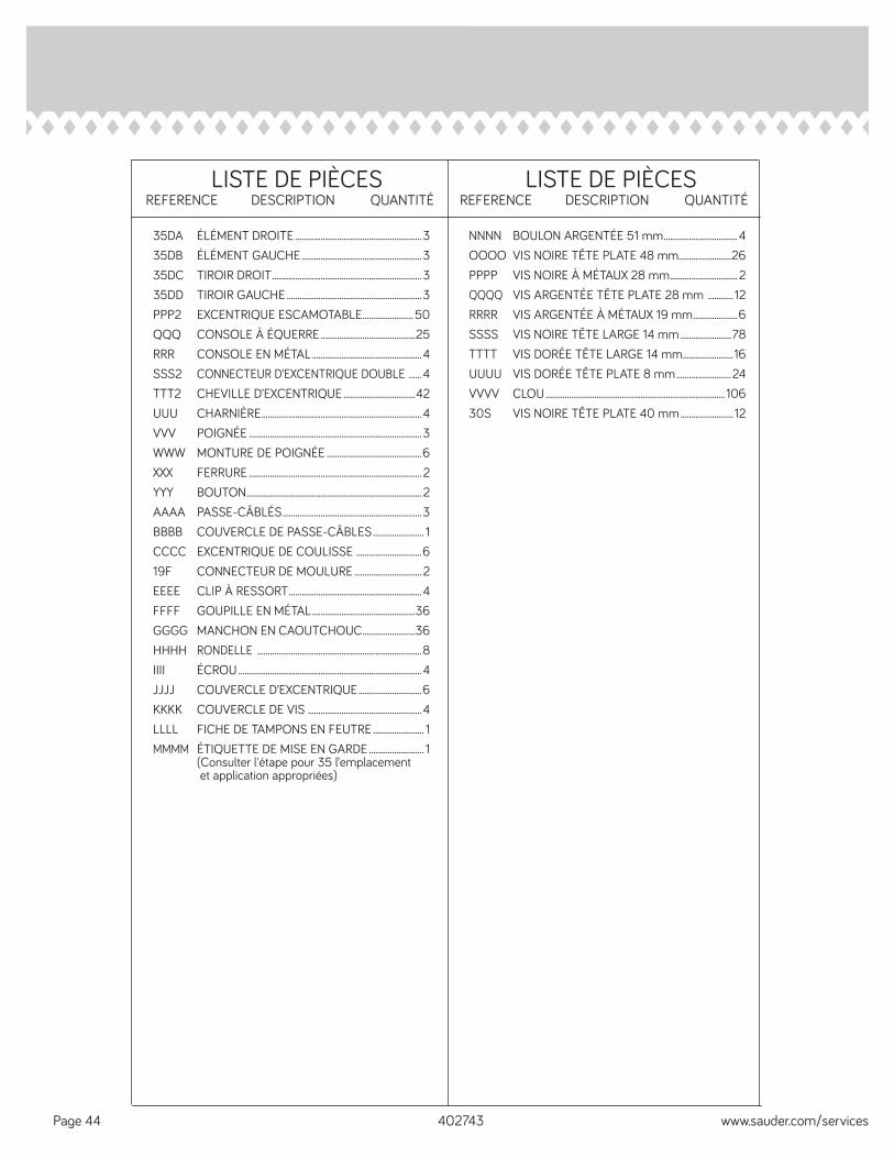
LISTE DE PIÈCESREFERENCE DESCRIPTION QUANTITÉ
NNNN BOULON ARGENTÉE 51 mm ...................................4OOOO VIS NOIRE TÊTE PLATE 48 mm.........................26PPPP VIS NOIRE À MÉTAUX 28 mm ................................ 2QQQQ VIS ARGENTÉE TÊTE PLATE 28 mm ............ 12RRRR VIS ARGENTÉE À MÉTAUX 19 mm .....................6SSSS VIS NOIRE TÊTE LARGE 14 mm ........................78TTTT VIS DORÉE TÊTE LARGE 14 mm ........................16UUUU VIS DORÉE TÊTE PLATE 8 mm ..........................24VVVV CLOU ..................................................................................... 10630S VIS NOIRE TÊTE PLATE 40 mm ......................... 12
35DA ÉLÉMENT DROITE ............................................................335DB ÉLÉMENT GAUCHE .........................................................335DC TIROIR DROIT .......................................................................335DD TIROIR GAUCHE ................................................................3PPP2 EXCENTRIQUE ESCAMOTABLE ........................ 50QQQ CONSOLE À ÉQUERRE .............................................25RRR CONSOLE EN MÉTAL ....................................................4SSS2 CONNECTEUR D’EXCENTRIQUE DOUBLE ......4TTT2 CHEVILLE D’EXCENTRIQUE ..................................42UUU CHARNIÈRE ............................................................................4VVV POIGNÉE ..................................................................................3WWW MONTURE DE POIGNÉE .............................................6XXX FERRURE .................................................................................. 2YYY BOUTON ................................................................................... 2AAAA PASSE-CÂBLÉS ..................................................................3BBBB COUVERCLE DE PASSE-CÂBLES ........................ 1CCCC EXCENTRIQUE DE COULISSE ...............................619F CONNECTEUR DE MOULURE ................................ 2EEEE CLIP À RESSORT ...............................................................4FFFF GOUPILLE EN MÉTAL .................................................36GGGG MANCHON EN CAOUTCHOUC .........................36HHHH RONDELLE ..............................................................................8IIII ÉCROU .......................................................................................4JJJJ COUVERCLE D’EXCENTRIQUE ..............................6KKKK COUVERCLE DE VIS ......................................................4LLLL FICHE DE TAMPONS EN FEUTRE ........................ 1MMMM ÉTIQUETTE DE MISE EN GARDE .......................... 1 (Consulter l'étape pour 35 l’emplacement et application appropriées)
LISTE DE PIÈCESREFERENCE DESCRIPTION QUANTITÉ
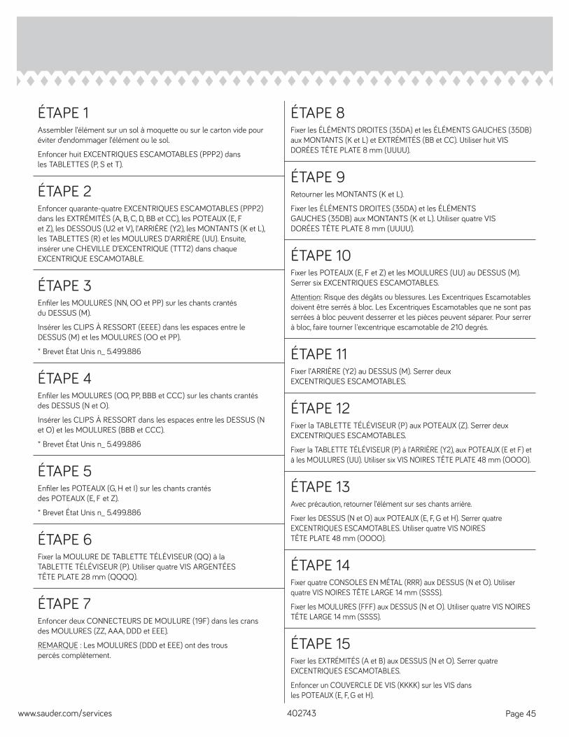
ÉTAPE 1Assembler l’élément sur un sol à moquette ou sur le carton vide pour éviter d’endommager l’élément ou le sol.
Enfoncer huit EXCENTRIQUES ESCAMOTABLES (PPP2) dans les TABLETTES (P, S et T).
ÉTAPE 2Enfoncer quarante-quatre EXCENTRIQUES ESCAMOTABLES (PPP2) dans les EXTRÉMITÉS (A, B, C, D, BB et CC), les POTEAUX (E, F et Z), les DESSOUS (U2 et V), l’ARRIÈRE (Y2), les MONTANTS (K et L), les TABLETTES (R) et les MOULURES D’ARRIÈRE (UU). Ensuite, insérer une CHEVILLE D’EXCENTRIQUE (TTT2) dans chaque EXCENTRIQUE ESCAMOTABLE.
ÉTAPE 8Fixer les ÉLÉMENTS DROITES (35DA) et les ÉLÉMENTS GAUCHES (35DB) aux MONTANTS (K et L) et EXTRÉMITÉS (BB et CC). Utiliser huit VIS DORÉES TÊTE PLATE 8 mm (UUUU).
ÉTAPE 9Retourner les MONTANTS (K et L).
Fixer les ÉLÉMENTS DROITES (35DA) et les ÉLÉMENTS GAUCHES (35DB) aux MONTANTS (K et L). Utiliser quatre VIS DORÉES TÊTE PLATE 8 mm (UUUU).
ÉTAPE 3Enfi ler les MOULURES (NN, OO et PP) sur les chants crantés du DESSUS (M).
Insérer les CLIPS À RESSORT (EEEE) dans les espaces entre le DESSUS (M) et les MOULURES (OO et PP).
* Brevet État Unis n_ 5.499.886
ÉTAPE 10Fixer les POTEAUX (E, F et Z) et les MOULURES (UU) au DESSUS (M). Serrer six EXCENTRIQUES ESCAMOTABLES.
Attention: Risque des dégâts ou blessures. Les Excentriques Escamotables doivent être serrés à bloc. Les Excentriques Escamotables que ne sont pas serrées à bloc peuvent desserrer et les pièces peuvent séparer. Pour serrer à bloc, faire tourner l'excentrique escamotable de 210 degrés.
ÉTAPE 4Enfi ler les MOULURES (OO, PP, BBB et CCC) sur les chants crantés des DESSUS (N et O).
Insérer les CLIPS À RESSORT dans les espaces entre les DESSUS (N et O) et les MOULURES (BBB et CCC).
* Brevet État Unis n_ 5.499.886
ÉTAPE 11Fixer l’ARRIÈRE (Y2) au DESSUS (M). Serrer deux EXCENTRIQUES ESCAMOTABLES.
ÉTAPE 5Enfi ler les POTEAUX (G, H et I) sur les chants crantés des POTEAUX (E, F et Z).
* Brevet État Unis n_ 5.499.886
ÉTAPE 12Fixer la TABLETTE TÉLÉVISEUR (P) aux POTEAUX (Z). Serrer deux EXCENTRIQUES ESCAMOTABLES.
Fixer la TABLETTE TÉLÉVISEUR (P) à l’ARRIÈRE (Y2), aux POTEAUX (E et F) et à les MOULURES (UU). Utiliser six VIS NOIRES TÊTE PLATE 48 mm (OOOO).
402743www.sauder.com/services Page 45
ÉTAPE 6Fixer la MOULURE DE TABLETTE TÉLÉVISEUR (QQ) à la TABLETTE TÉLÉVISEUR (P). Utiliser quatre VIS ARGENTÉES TÊTE PLATE 28 mm (QQQQ).
ÉTAPE 7Enfoncer deux CONNECTEURS DE MOULURE (19F) dans les crans des MOULURES (ZZ, AAA, DDD et EEE).
REMARQUE : Les MOULURES (DDD et EEE) ont des trous percés complètement.
ÉTAPE 13Avec précaution, retourner l’élément sur ses chants arrière.
Fixer les DESSUS (N et O) aux POTEAUX (E, F, G et H). Serrer quatre EXCENTRIQUES ESCAMOTABLES. Utiliser quatre VIS NOIRES TÊTE PLATE 48 mm (OOOO).
ÉTAPE 14Fixer quatre CONSOLES EN MÉTAL (RRR) aux DESSUS (N et O). Utiliser quatre VIS NOIRES TÊTE LARGE 14 mm (SSSS).
Fixer les MOULURES (FFF) aux DESSUS (N et O). Utiliser quatre VIS NOIRES TÊTE LARGE 14 mm (SSSS).
ÉTAPE 15Fixer les EXTRÉMITÉS (A et B) aux DESSUS (N et O). Serrer quatre EXCENTRIQUES ESCAMOTABLES.
Enfoncer un COUVERCLE DE VIS (KKKK) sur les VIS dans les POTEAUX (E, F, G et H).
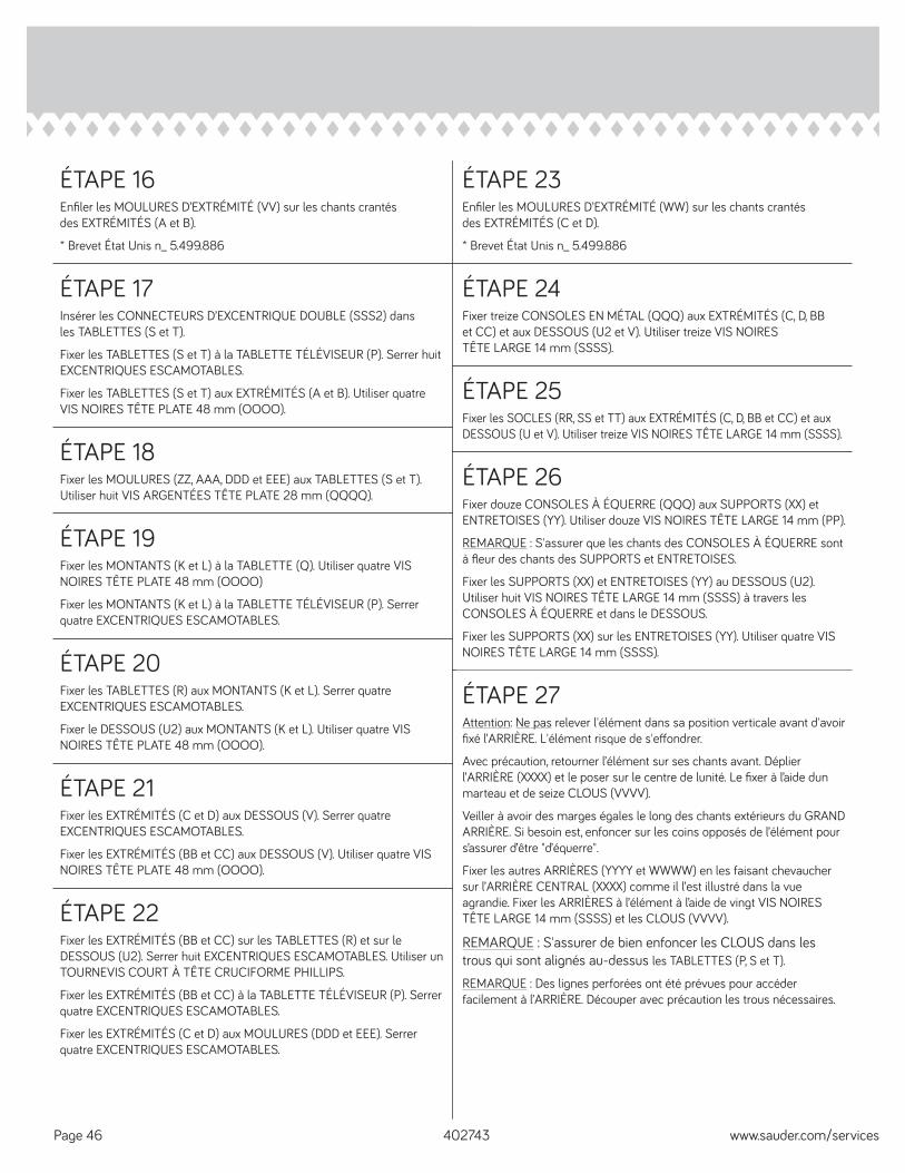
ÉTAPE 16Enfi ler les MOULURES D’EXTRÉMITÉ (VV) sur les chants crantés des EXTRÉMITÉS (A et B).
* Brevet État Unis n_ 5.499.886
ÉTAPE 17Insérer les CONNECTEURS D’EXCENTRIQUE DOUBLE (SSS2) dans les TABLETTES (S et T).
Fixer les TABLETTES (S et T) à la TABLETTE TÉLÉVISEUR (P). Serrer huit EXCENTRIQUES ESCAMOTABLES.
Fixer les TABLETTES (S et T) aux EXTRÉMITÉS (A et B). Utiliser quatre VIS NOIRES TÊTE PLATE 48 mm (OOOO).
ÉTAPE 23Enfi ler les MOULURES D’EXTRÉMITÉ (WW) sur les chants crantés des EXTRÉMITÉS (C et D).
* Brevet État Unis n_ 5.499.886
ÉTAPE 18Fixer les MOULURES (ZZ, AAA, DDD et EEE) aux TABLETTES (S et T). Utiliser huit VIS ARGENTÉES TÊTE PLATE 28 mm (QQQQ).
ÉTAPE 24Fixer treize CONSOLES EN MÉTAL (QQQ) aux EXTRÉMITÉS (C, D, BB et CC) et aux DESSOUS (U2 et V). Utiliser treize VIS NOIRES TÊTE LARGE 14 mm (SSSS).
ÉTAPE 19Fixer les MONTANTS (K et L) à la TABLETTE (Q). Utiliser quatre VIS NOIRES TÊTE PLATE 48 mm (OOOO)
Fixer les MONTANTS (K et L) à la TABLETTE TÉLÉVISEUR (P). Serrer quatre EXCENTRIQUES ESCAMOTABLES.
ÉTAPE 25Fixer les SOCLES (RR, SS et TT) aux EXTRÉMITÉS (C, D, BB et CC) et aux DESSOUS (U et V). Utiliser treize VIS NOIRES TÊTE LARGE 14 mm (SSSS).
ÉTAPE 27Attention: Ne pas relever l'élément dans sa position verticale avant d'avoir fi xé l’ARRIÈRE. L'élément risque de s'eff ondrer.
Avec précaution, retourner l’élément sur ses chants avant. Déplier l’ARRIÈRE (XXXX) et le poser sur le centre de lunité. Le fi xer à l’aide dun marteau et de seize CLOUS (VVVV).
Veiller à avoir des marges égales le long des chants extérieurs du GRAND ARRIÈRE. Si besoin est, enfoncer sur les coins opposés de l’élément pour s’assurer d’être "d’équerre".
Fixer les autres ARRIÈRES (YYYY et WWWW) en les faisant chevaucher sur l’ARRIÈRE CENTRAL (XXXX) comme il l’est illustré dans la vue agrandie. Fixer les ARRIÈRES à l’élément à l’aide de vingt VIS NOIRES TÊTE LARGE 14 mm (SSSS) et les CLOUS (VVVV).
REMARQUE : S'assurer de bien enfoncer les CLOUS dans les trous qui sont alignés au-dessus les TABLETTES (P, S et T).
REMARQUE : Des lignes perforées ont été prévues pour accéder facilement à l’ARRIÈRE. Découper avec précaution les trous nécessaires.
402743 www.sauder.com/servicesPage 46
ÉTAPE 20Fixer les TABLETTES (R) aux MONTANTS (K et L). Serrer quatre EXCENTRIQUES ESCAMOTABLES.
Fixer le DESSOUS (U2) aux MONTANTS (K et L). Utiliser quatre VIS NOIRES TÊTE PLATE 48 mm (OOOO).
ÉTAPE 21Fixer les EXTRÉMITÉS (C et D) aux DESSOUS (V). Serrer quatre EXCENTRIQUES ESCAMOTABLES.
Fixer les EXTRÉMITÉS (BB et CC) aux DESSOUS (V). Utiliser quatre VIS NOIRES TÊTE PLATE 48 mm (OOOO).
ÉTAPE 22Fixer les EXTRÉMITÉS (BB et CC) sur les TABLETTES (R) et sur le DESSOUS (U2). Serrer huit EXCENTRIQUES ESCAMOTABLES. Utiliser un TOURNEVIS COURT À TÊTE CRUCIFORME PHILLIPS.
Fixer les EXTRÉMITÉS (BB et CC) à la TABLETTE TÉLÉVISEUR (P). Serrer quatre EXCENTRIQUES ESCAMOTABLES.
Fixer les EXTRÉMITÉS (C et D) aux MOULURES (DDD et EEE). Serrer quatre EXCENTRIQUES ESCAMOTABLES.
ÉTAPE 26Fixer douze CONSOLES À ÉQUERRE (QQQ) aux SUPPORTS (XX) et ENTRETOISES (YY). Utiliser douze VIS NOIRES TÊTE LARGE 14 mm (PP).
REMARQUE : S'assurer que les chants des CONSOLES À ÉQUERRE sont à fl eur des chants des SUPPORTS et ENTRETOISES.
Fixer les SUPPORTS (XX) et ENTRETOISES (YY) au DESSOUS (U2). Utiliser huit VIS NOIRES TÊTE LARGE 14 mm (SSSS) à travers les CONSOLES À ÉQUERRE et dans le DESSOUS.
Fixer les SUPPORTS (XX) sur les ENTRETOISES (YY). Utiliser quatre VIS NOIRES TÊTE LARGE 14 mm (SSSS).
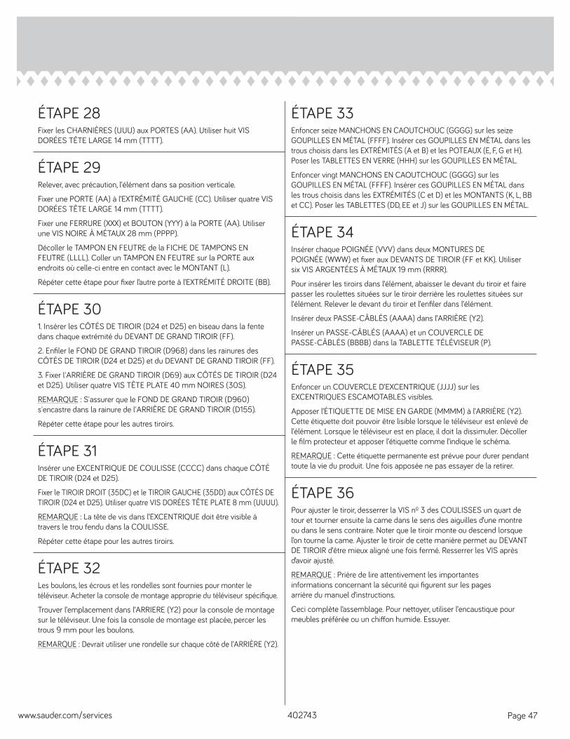
ÉTAPE 28Fixer les CHARNIÈRES (UUU) aux PORTES (AA). Utiliser huit VIS DORÉES TÊTE LARGE 14 mm (TTTT).
ÉTAPE 29Relever, avec précaution, l’élément dans sa position verticale.
Fixer une PORTE (AA) à l’EXTRÉMITÉ GAUCHE (CC). Utiliser quatre VIS DORÉES TÊTE LARGE 14 mm (TTTT).
Fixer une FERRURE (XXX) et BOUTON (YYY) à la PORTE (AA). Utiliser une VIS NOIRE À MÉTAUX 28 mm (PPPP).
Décoller le TAMPON EN FEUTRE de la FICHE DE TAMPONS EN FEUTRE (LLLL). Coller un TAMPON EN FEUTRE sur la PORTE aux endroits où celle-ci entre en contact avec le MONTANT (L).
Répéter cette étape pour fi xer l’autre porte à l’EXTRÉMITÉ DROITE (BB).
ÉTAPE 33Enfoncer seize MANCHONS EN CAOUTCHOUC (GGGG) sur les seize GOUPILLES EN MÉTAL (FFFF). Insérer ces GOUPILLES EN MÉTAL dans les trous choisis dans les EXTRÉMITÉS (A et B) et les POTEAUX (E, F, G et H). Poser les TABLETTES EN VERRE (HHH) sur les GOUPILLES EN MÉTAL.
Enfoncer vingt MANCHONS EN CAOUTCHOUC (GGGG) sur les GOUPILLES EN MÉTAL (FFFF). Insérer ces GOUPILLES EN MÉTAL dans les trous choisis dans les EXTRÉMITÉS (C et D) et les MONTANTS (K, L, BB et CC). Poser les TABLETTES (DD, EE et J) sur les GOUPILLES EN MÉTAL.
ÉTAPE 34Insérer chaque POIGNÉE (VVV) dans deux MONTURES DE POIGNÉE (WWW) et fi xer aux DEVANTS DE TIROIR (FF et KK). Utiliser six VIS ARGENTÉES À MÉTAUX 19 mm (RRRR).
Pour insérer les tiroirs dans l’élément, abaisser le devant du tiroir et faire passer les roulettes situées sur le tiroir derrière les roulettes situées sur l’élément. Relever le devant du tiroir et l’enfi ler dans l’élément.
Insérer deux PASSE-CÂBLÉS (AAAA) dans l’ARRIÈRE (Y2).
Insérer un PASSE-CÂBLÉS (AAAA) et un COUVERCLE DE PASSE-CÂBLÉS (BBBB) dans la TABLETTE TÉLÉVISEUR (P).
ÉTAPE 301. Insérer les CÔTÉS DE TIROIR (D24 et D25) en biseau dans la fente dans chaque extrémité du DEVANT DE GRAND TIROIR (FF).
2. Enfi ler le FOND DE GRAND TIROIR (D968) dans les rainures des CÔTÉS DE TIROIR (D24 et D25) et du DEVANT DE GRAND TIROIR (FF).
3. Fixer l'ARRIÈRE DE GRAND TIROIR (D69) aux CÔTÉS DE TIROIR (D24 et D25). Utiliser quatre VIS TÊTE PLATE 40 mm NOIRES (30S).
REMARQUE : S'assurer que le FOND DE GRAND TIROIR (D960) s'encastre dans la rainure de l'ARRIÈRE DE GRAND TIROIR (D155).
Répéter cette étape pour les autres tiroirs.
ÉTAPE 31Insérer une EXCENTRIQUE DE COULISSE (CCCC) dans chaque CÔTÉ DE TIROIR (D24 et D25).
Fixer le TIROIR DROIT (35DC) et le TIROIR GAUCHE (35DD) aux CÔTÉS DE TIROIR (D24 et D25). Utiliser quatre VIS DORÉES TÊTE PLATE 8 mm (UUUU).
REMARQUE : La tête de vis dans l’EXCENTRIQUE doit être visible à travers le trou fendu dans la COULISSE.
Répéter cette étape pour les autres tiroirs.
ÉTAPE 35Enfoncer un COUVERCLE D’EXCENTRIQUE (JJJJ) sur les EXCENTRIQUES ESCAMOTABLES visibles.
Apposer l’ÉTIQUETTE DE MISE EN GARDE (MMMM) à l’ARRIÈRE (Y2). Cette étiquette doit pouvoir être lisible lorsque le téléviseur est enlevé de l’élément. Lorsque le téléviseur est en place, il doit la dissimuler. Décoller le fi lm protecteur et apposer l’étiquette comme l’indique le schéma.
REMARQUE : Cette étiquette permanente est prévue pour durer pendant toute la vie du produit. Une fois apposée ne pas essayer de la retirer.
ÉTAPE 32Les boulons, les écrous et les rondelles sont fournies pour monter le téléviseur. Acheter la console de montage approprie du téléviseur spécifi que.
Trouver l’emplacement dans l’ARRIERE (Y2) pour la console de montage sur le téléviseur. Une fois la console de montage est placée, percer les trous 9 mm pour les boulons.
REMARQUE : Devrait utiliser une rondelle sur chaque côté de l’ARRIÈRE (Y2).
ÉTAPE 36Pour ajuster le tiroir, desserrer la VIS nº 3 des COULISSES un quart de tour et tourner ensuite la came dans le sens des aiguilles d’une montre ou dans le sens contraire. Noter que le tiroir monte ou descend lorsque l’on tourne la came. Ajuster le tiroir de cette manière permet au DEVANT DE TIROIR d’être mieux aligné une fois fermé. Resserrer les VIS après d’avoir ajusté.
REMARQUE : Prière de lire attentivement les importantes informations concernant la sécurité qui fi gurent sur les pages arrière du manuel d’instructions.
Ceci complète l’assemblage. Pour nettoyer, utiliser l’encaustique pour meubles préférée ou un chiff on humide. Essuyer.
402743www.sauder.com/services Page 47
A l’usage exclusif du Canada Noter la date d’achat de cet élément et conserver le livret pour future référence. Pour contacter Sauder en ce qui concerne cet élément, faire référence au numéro de lot et numéro de modèle en appelant notre numéro sans frais.
Lot nº : ____________
Date del’achat: ____________
LISTA DE PARTESITEM DESCRIPCIÓN CANTIDAD
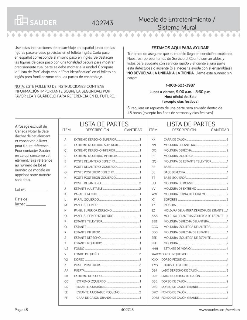
ESTAMOS AQUI PARA AYUDAR!Tratamos de asegurar que su mueble llega en condición excelente. Nuestros representantes de Servicio al Cliente son amables y listos para ayudarle con servicio rápido y efi ciente si una parte está defectuosa o ausente (o si necesita ayuda con el ensamblaje). NO DEVUELVA LA UNIDAD A LA TIENDA. Llame este número sin cargo:
1-800-523-3987Lunes a viernes, 9:00 a.m. - 5:30 p.m.
Hora ofi cial del Este(excepto días festivos)
Si requiere un repuesto de una parte, será enviado dentro de 48 horas (excepto los fi nes de semana y días festivos)
Use estas instrucciones de ensamblaje en español junto con las fi guras paso-a-paso provistas en el folleto inglés. Cada paso en español corresponde al mismo paso en inglés. Se destacan las fi guras de cada paso con una tonalidad oscura para mostrar precisamente cual parte se debe montar a la unidad. Compare la “Lista de Part” abajo con la “Part Identifi cation” en el folleto en inglés para familiarizarse con Las partes de ensamblaje.
NOTA: ESTE FOLLETO DE INSTRUCCIONES CONTIENE INFORMACIÓN IMPORTANTE SOBRE LA SEGURIDAD. POR FAVOR LEA Y GUÁRDELO PARA REFERENCIA EN EL FUTURO.
KK CARA DE CAJÓN .............................................................................2
NN MOLDURA DELANTERA ............................................................. 1
OO MOLDURA DERECHA ..................................................................2
PP MOLDURA IZQUIERDA ...............................................................2
QQ MOLDURA DE ESTANTE TELEVISOR .............................. 1
RR BASE ........................................................................................................... 1
SS BASE DERECHA ................................................................................ 1
TT BASE IZQUIERDA ............................................................................. 1
UU MOLDURA DE DORSO ..............................................................2
VV MOLDURA DE EXTREMO .........................................................2
WW MOLDURA CORTA DE EXTREMO ......................................2
XX SOPORTE .............................................................................................2
YY RIOSTRA .................................................................................................2
ZZ MOLDURA DELANTERA DERECHA DE ESTANTE ...... 1
AAA MOLDURA DELANTERA IZQUIERDA DE ESTANTE ...... 1
BBB MOLDURA DERECHA DELANTERA .................................. 1
CCC MOLDURA IZQUIERDA DELANTERA ............................... 1
DDD MOLDURA DERECHA DE ESTANTE ................................. 1
EEE MOLDURA IZQUIERDA DE ESTANTE .............................. 1
FFF MOLDURA .............................................................................................2
HHH ESTANTE DE VIDRIO.....................................................................4
WWWW DORSO IZQUIERDO ............................................................................ 1
XXXX DORSO PEQUEÑO .............................................................................. 1
YYYY DORSO DERECHO .......................................................................... 1
D24 LADO DERECHO DE CAJÓN......................................................3
D25 LADO IZQUIERDO DE CAJÓN ..................................................3
D65 DORSO DE CAJÓN .............................................................................2
D69 DORSO DE CAJÓN GRANDE ...................................................... 1
D701 FONDO DE CAJÓN.............................................................................2
D968 FONDO DE CAJÓN GRANDE ...................................................... 1
A EXTREMO DERECHO SUPERIOR............................................. 1
B EXTREMO IZQUIERDO SUPERIOR ......................................... 1
C EXTREMO DERECHO INFERIOR ............................................... 1
D EXTREMO IZQUIERDO INFERIOR ............................................ 1
E POSTE DELANTERO DERECHO ............................................... 1
F POSTE DELANTERO IZQUIERDO ............................................ 1
G POSTE POSTERIOR DERECHO ................................................. 1
H POSTE POSTERIOR IZQUIERDO ............................................. 1
I POSTE DELANTERO .........................................................................2
J ESTANTE AJUSTABLE ......................................................................2
K PARAL DERECHO ................................................................................ 1
L PARAL IZQUIERDO .............................................................................. 1
M PANEL SUPERIOR ................................................................................. 1
N PANEL SUPERIOR DERECHO ..................................................... 1
O PANEL SUPERIOR IZQUIERDO .................................................. 1
P ESTANTE TELEVISOR ........................................................................ 1
Q ESTANTE ...................................................................................................... 1
R ESTANTE INFERIOR ............................................................................ 1
S ESTANTE DERECHO ........................................................................... 1
T ESTANTE IZQUIERDO ........................................................................ 1
U2 FONDO .......................................................................................................... 1
V FONDO PEQUEÑO .............................................................................2
Y2 DORSO .......................................................................................................... 1
Z POSTE POSTERIOR ...........................................................................2
AA PUERTA ........................................................................................................2
BB EXTREMO DERECHO ......................................................................... 1
CC EXTREMO IZQUIERDO ............................................................... 1
DD ESTANTE AJUSTABLE .................................................................. 1
EE ESTANTE AJUSTABLE PEQUEÑO .....................................2
FF CARA DE CAJÓN GRANDE ...................................................... 1
LISTA DE PARTESITEM DESCRIPCIÓN CANTIDAD
Mueble de Entretenimiento / Sistema Mural
402743
402743 www.sauder.com/servicesPage 48
LISTA DE PARTESITEM DESCRIPCIÓN CANTIDAD
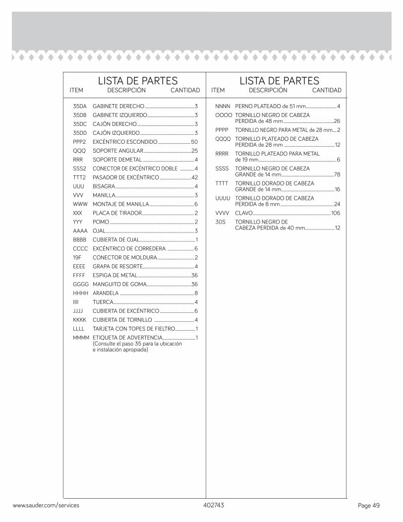
NNNN PERNO PLATEADO de 51 mm ................................4OOOO TORNILLO NEGRO DE CABEZA PERDIDA de 48 mm .....................................................26PPPP TORNILLO NEGRO PARA METAL de 28 mm .... 2QQQQ TORNILLO PLATEADO DE CABEZA PERDIDA de 28 mm ..................................................... 12RRRR TORNILLO PLATEADO PARA METAL de 19 mm ..................................................................................6SSSS TORNILLO NEGRO DE CABEZA GRANDE de 14 mm .......................................................78TTTT TORNILLO DORADO DE CABEZA GRANDE de 14 mm ........................................................16UUUU TORNILLO DORADO DE CABEZA PERDIDA de 8 mm ........................................................24VVVV CLAVO .................................................................................. 10630S TORNILLO NEGRO DE CABEZA PERDIDA de 40 mm ............................... 12
35DA GABINETE DERECHO ....................................................335DB GABINETE IZQUIERDO .................................................335DC CAJÓN DERECHO ............................................................335DD CAJÓN IZQUIERDO .........................................................3PPP2 EXCÉNTRICO ESCONDIDO .................................. 50QQQ SOPORTE ANGULAR ..................................................25RRR SOPORTE DEMETAL ......................................................4SSS2 CONECTOR DE EXCÉNTRICO DOBLE ...............4TTT2 PASADOR DE EXCÉNTRICO .................................42UUU BISAGRA ...................................................................................4VVV MANILLA...................................................................................3WWW MONTAJE DE MANILLA ...............................................6XXX PLACA DE TIRADOR ....................................................... 2YYY POMO ......................................................................................... 2AAAA OJAL .............................................................................................3BBBB CUBIERTA DE OJAL .......................................................... 1CCCC EXCÉNTRICO DE CORREDERA ............................619F CONECTOR DE MOLDURA ....................................... 2EEEE GRAPA DE RESORTE......................................................4FFFF ESPIGA DE METAL ........................................................36GGGG MANGUITO DE GOMA...............................................36HHHH ARANDELA ..............................................................................8IIII TUERCA .....................................................................................4JJJJ CUBIERTA DE EXCÉNTRICO ....................................6KKKK CUBIERTA DE TORNILLO ..........................................4LLLL TARJETA CON TOPES DE FIELTRO ..................... 1MMMM ETIQUETA DE ADVERTENCIA .................................. 1 (Consulte el paso 35 para la ubicación e instalación apropiada)
LISTA DE PARTESITEM DESCRIPCIÓN CANTIDAD
402743www.sauder.com/services Page 49
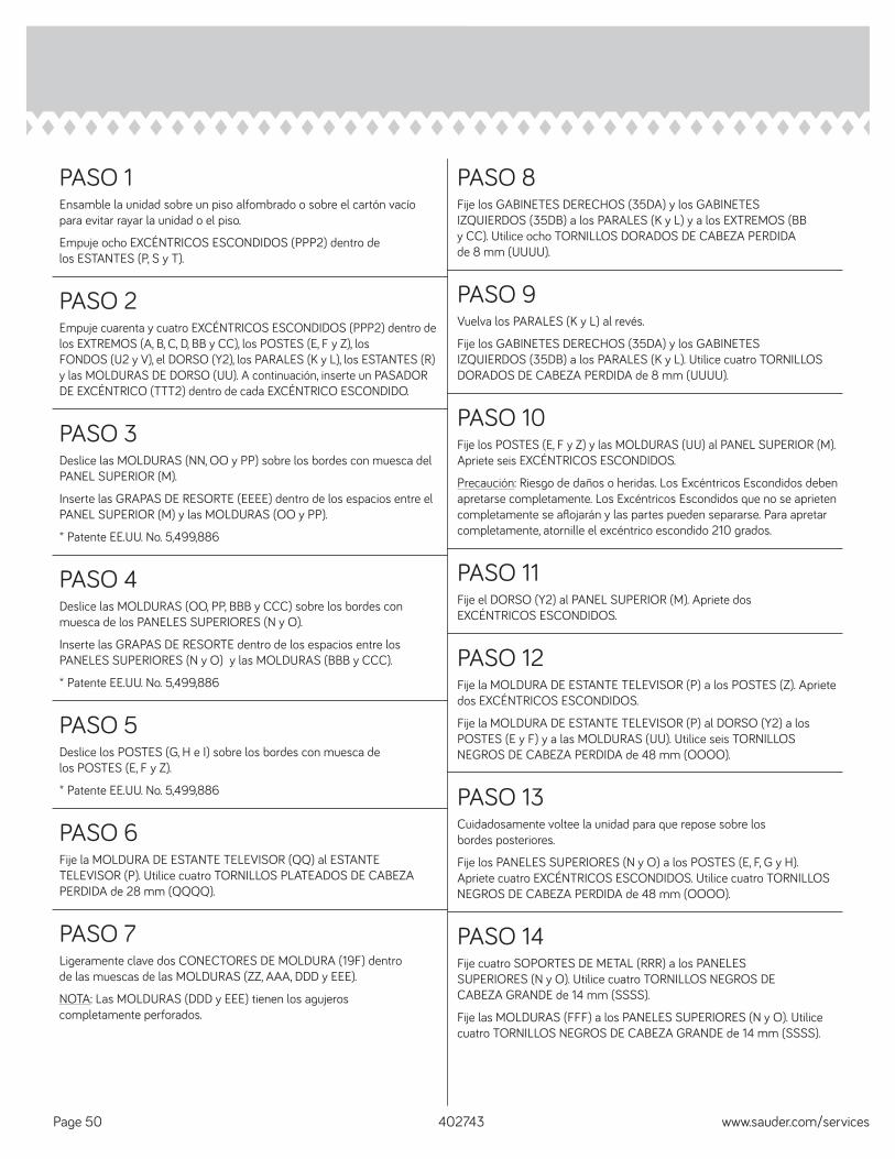
PASO 1Ensamble la unidad sobre un piso alfombrado o sobre el cartón vacío para evitar rayar la unidad o el piso.
Empuje ocho EXCÉNTRICOS ESCONDIDOS (PPP2) dentro de los ESTANTES (P, S y T).
PASO 2Empuje cuarenta y cuatro EXCÉNTRICOS ESCONDIDOS (PPP2) dentro de los EXTREMOS (A, B, C, D, BB y CC), los POSTES (E, F y Z), los FONDOS (U2 y V), el DORSO (Y2), los PARALES (K y L), los ESTANTES (R) y las MOLDURAS DE DORSO (UU). A continuación, inserte un PASADOR DE EXCÉNTRICO (TTT2) dentro de cada EXCÉNTRICO ESCONDIDO.
PASO 8Fije los GABINETES DERECHOS (35DA) y los GABINETES IZQUIERDOS (35DB) a los PARALES (K y L) y a los EXTREMOS (BB y CC). Utilice ocho TORNILLOS DORADOS DE CABEZA PERDIDA de 8 mm (UUUU).
PASO 9Vuelva los PARALES (K y L) al revés.
Fije los GABINETES DERECHOS (35DA) y los GABINETES IZQUIERDOS (35DB) a los PARALES (K y L). Utilice cuatro TORNILLOS DORADOS DE CABEZA PERDIDA de 8 mm (UUUU).
PASO 3Deslice las MOLDURAS (NN, OO y PP) sobre los bordes con muesca del PANEL SUPERIOR (M).
Inserte las GRAPAS DE RESORTE (EEEE) dentro de los espacios entre el PANEL SUPERIOR (M) y las MOLDURAS (OO y PP).
* Patente EE.UU. No. 5,499,886
PASO 10Fije los POSTES (E, F y Z) y las MOLDURAS (UU) al PANEL SUPERIOR (M). Apriete seis EXCÉNTRICOS ESCONDIDOS.
Precaución: Riesgo de daños o heridas. Los Excéntricos Escondidos deben apretarse completamente. Los Excéntricos Escondidos que no se aprieten completamente se afl ojarán y las partes pueden separarse. Para apretar completamente, atornille el excéntrico escondido 210 grados.
PASO 4Deslice las MOLDURAS (OO, PP, BBB y CCC) sobre los bordes con muesca de los PANELES SUPERIORES (N y O).
Inserte las GRAPAS DE RESORTE dentro de los espacios entre los PANELES SUPERIORES (N y O) y las MOLDURAS (BBB y CCC).
* Patente EE.UU. No. 5,499,886
PASO 11Fije el DORSO (Y2) al PANEL SUPERIOR (M). Apriete dos EXCÉNTRICOS ESCONDIDOS.
PASO 5Deslice los POSTES (G, H e I) sobre los bordes con muesca de los POSTES (E, F y Z).
* Patente EE.UU. No. 5,499,886
PASO 12Fije la MOLDURA DE ESTANTE TELEVISOR (P) a los POSTES (Z). Apriete dos EXCÉNTRICOS ESCONDIDOS.
Fije la MOLDURA DE ESTANTE TELEVISOR (P) al DORSO (Y2) a los POSTES (E y F) y a las MOLDURAS (UU). Utilice seis TORNILLOS NEGROS DE CABEZA PERDIDA de 48 mm (OOOO).
402743 www.sauder.com/servicesPage 50
PASO 6Fije la MOLDURA DE ESTANTE TELEVISOR (QQ) al ESTANTE TELEVISOR (P). Utilice cuatro TORNILLOS PLATEADOS DE CABEZA PERDIDA de 28 mm (QQQQ).
PASO 7Ligeramente clave dos CONECTORES DE MOLDURA (19F) dentro de las muescas de las MOLDURAS (ZZ, AAA, DDD y EEE).
NOTA: Las MOLDURAS (DDD y EEE) tienen los agujeros completamente perforados.
PASO 13Cuidadosamente voltee la unidad para que repose sobre los bordes posteriores.
Fije los PANELES SUPERIORES (N y O) a los POSTES (E, F, G y H). Apriete cuatro EXCÉNTRICOS ESCONDIDOS. Utilice cuatro TORNILLOS NEGROS DE CABEZA PERDIDA de 48 mm (OOOO).
PASO 14Fije cuatro SOPORTES DE METAL (RRR) a los PANELES SUPERIORES (N y O). Utilice cuatro TORNILLOS NEGROS DE CABEZA GRANDE de 14 mm (SSSS).
Fije las MOLDURAS (FFF) a los PANELES SUPERIORES (N y O). Utilice cuatro TORNILLOS NEGROS DE CABEZA GRANDE de 14 mm (SSSS).
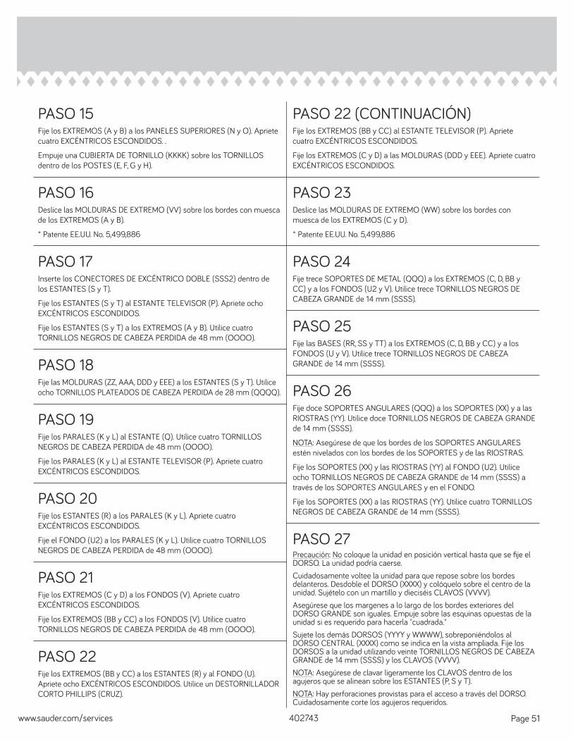
PASO 15Fije los EXTREMOS (A y B) a los PANELES SUPERIORES (N y O). Apriete cuatro EXCÉNTRICOS ESCONDIDOS. .
Empuje una CUBIERTA DE TORNILLO (KKKK) sobre los TORNILLOS dentro de los POSTES (E, F, G y H).
PASO 16Deslice las MOLDURAS DE EXTREMO (VV) sobre los bordes con muesca de los EXTREMOS (A y B).
* Patente EE.UU. No. 5,499,886
PASO 22 (CONTINUACIÓN)Fije los EXTREMOS (BB y CC) al ESTANTE TELEVISOR (P). Apriete cuatro EXCÉNTRICOS ESCONDIDOS.
Fije los EXTREMOS (C y D) a las MOLDURAS (DDD y EEE). Apriete cuatro EXCÉNTRICOS ESCONDIDOS.
PASO 23Deslice las MOLDURAS DE EXTREMO (WW) sobre los bordes con muesca de los EXTREMOS (C y D).
* Patente EE.UU. No. 5,499,886
PASO 17Inserte los CONECTORES DE EXCÉNTRICO DOBLE (SSS2) dentro de los ESTANTES (S y T).
Fije los ESTANTES (S y T) al ESTANTE TELEVISOR (P). Apriete ocho EXCÉNTRICOS ESCONDIDOS.
Fije los ESTANTES (S y T) a los EXTREMOS (A y B). Utilice cuatro TORNILLOS NEGROS DE CABEZA PERDIDA de 48 mm (OOOO).
PASO 24Fije trece SOPORTES DE METAL (QQQ) a los EXTREMOS (C, D, BB y CC) y a los FONDOS (U2 y V). Utilice trece TORNILLOS NEGROS DE CABEZA GRANDE de 14 mm (SSSS).
PASO 18Fije las MOLDURAS (ZZ, AAA, DDD y EEE) a los ESTANTES (S y T). Utilice ocho TORNILLOS PLATEADOS DE CABEZA PERDIDA de 28 mm (QQQQ).
PASO 25Fije las BASES (RR, SS y TT) a los EXTREMOS (C, D, BB y CC) y a los FONDOS (U y V). Utilice trece TORNILLOS NEGROS DE CABEZA GRANDE de 14 mm (SSSS).
PASO 19Fije los PARALES (K y L) al ESTANTE (Q). Utilice cuatro TORNILLOS NEGROS DE CABEZA PERDIDA de 48 mm (OOOO).
Fije los PARALES (K y L) al ESTANTE TELEVISOR (P). Apriete cuatro EXCÉNTRICOS ESCONDIDOS.
PASO 26Fije doce SOPORTES ANGULARES (QQQ) a los SOPORTES (XX) y a las RIOSTRAS (YY). Utilice doce TORNILLOS NEGROS DE CABEZA GRANDE de 14 mm (SSSS).
NOTA: Asegúrese de que los bordes de los SOPORTES ANGULARES estén nivelados con los bordes de los SOPORTES y de las RIOSTRAS.
Fije los SOPORTES (XX) y las RIOSTRAS (YY) al FONDO (U2). Utilice ocho TORNILLOS NEGROS DE CABEZA GRANDE de 14 mm (SSSS) a través de los SOPORTES ANGULARES y en el FONDO.
Fije los SOPORTES (XX) a las RIOSTRAS (YY). Utilice cuatro TORNILLOS NEGROS DE CABEZA GRANDE de 14 mm (SSSS).
402743www.sauder.com/services Page 51
PASO 20Fije los ESTANTES (R) a los PARALES (K y L). Apriete cuatro EXCÉNTRICOS ESCONDIDOS.
Fije el FONDO (U2) a los PARALES (K y L). Utilice cuatro TORNILLOS NEGROS DE CABEZA PERDIDA de 48 mm (OOOO).
PASO 21Fije los EXTREMOS (C y D) a los FONDOS (V). Apriete cuatro EXCÉNTRICOS ESCONDIDOS.
Fije los EXTREMOS (BB y CC) a los FONDOS (V). Utilice cuatro TORNILLOS NEGROS DE CABEZA PERDIDA de 48 mm (OOOO).
PASO 27Precaución: No coloque la unidad en posición vertical hasta que se fi je el DORSO. La unidad podría caerse.Cuidadosamente voltee la unidad para que repose sobre los bordes delanteros. Desdoble el DORSO (XXXX) y colóquelo sobre el centro de la unidad. Sujételo con un martillo y dieciséis CLAVOS (VVVV).Asegúrese que los margenes a lo largo de los bordes exteriores del DORSO GRANDE son iguales. Empuje sobre las esquinas opuestas de la unidad si es requerido para hacerla "cuadrada."Sujete los demás DORSOS (YYYY y WWWW), sobreponiéndolos al DORSO CENTRAL (XXXX) como se indica en la vista ampliada. Fije los DORSOS a la unidad utilizando veinte TORNILLOS NEGROS DE CABEZA GRANDE de 14 mm (SSSS) y los CLAVOS (VVVV).NOTA: Asegúrese de clavar ligeramente los CLAVOS dentro de los agujeros que se alinean sobre los ESTANTES (P, S y T).NOTA: Hay perforaciones provistas para el acceso a través del DORSO. Cuidadosamente corte los agujeros requeridos.
PASO 22Fije los EXTREMOS (BB y CC) a los ESTANTES (R) y al FONDO (U). Apriete ocho EXCÉNTRICOS ESCONDIDOS. Utilice un DESTORNILLADOR CORTO PHILLIPS (CRUZ).
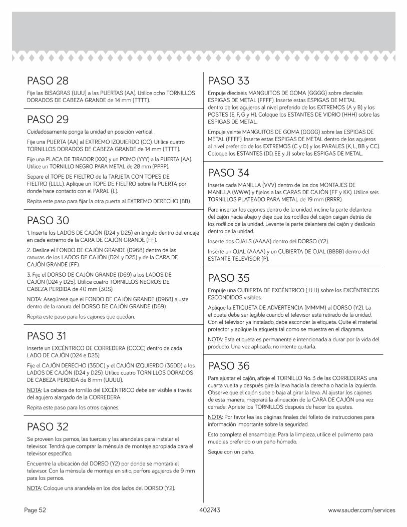
PASO 28Fije las BISAGRAS (UUU) a las PUERTAS (AA). Utilice ocho TORNILLOS DORADOS DE CABEZA GRANDE de 14 mm (TTTT).
PASO 29Cuidadosamente ponga la unidad en posición vertical.
Fije una PUERTA (AA) al EXTREMO IZQUIERDO (CC). Utilice cuatro TORNILLOS DORADOS DE CABEZA GRANDE de 14 mm (TTTT).
Fije una PLACA DE TIRADOR (XXX) y un POMO (YYY) a la PUERTA (AA). Utilice un TORNILLO NEGRO PARA METAL de 28 mm (PPPP).
Separe el TOPE DE FIELTRO de la TARJETA CON TOPES DE FIELTRO (LLLL). Aplique un TOPE DE FIELTRO sobre la PUERTA por donde hace contacto con el PARAL (L).
Repita este paso para fi jar la otra puerta al EXTREMO DERECHO (BB).
PASO 33Empuje dieciséis MANGUITOS DE GOMA (GGGG) sobre dieciséis ESPIGAS DE METAL (FFFF). Inserte estas ESPIGAS DE METAL dentro de los agujeros al nivel preferido de los EXTREMOS (A y B) y los POSTES (E, F, G y H). Coloque los ESTANTES DE VIDRIO (HHH) sobre las ESPIGAS DE METAL.
Empuje veinte MANGUITOS DE GOMA (GGGG) sobre las ESPIGAS DE METAL (FFFF). Inserte estas ESPIGAS DE METAL dentro de los agujeros al nivel preferido de los EXTREMOS (C y D) y los PARALES (K, L, BB y CC). Coloque los ESTANTES (DD, EE y J) sobre las ESPIGAS DE METAL.
PASO 34Inserte cada MANILLA (VVV) dentro de los dos MONTAJES DE MANILLA (WWW) y fi jelos a las CARAS DE CAJÓN (FF y KK). Utilice seis TORNILLOS PLATEADO PARA METAL de 19 mm (RRRR).
Para insertar los cajones dentro de la unidad, incline la parte delantera del cajón hacia abajo y deje que los rodillos del cajón caigan detrás de los rodillos de la unidad. Levante la parte delantera del cajón y deslícelo dentro de la unidad.
Inserte dos OJALS (AAAA) dentro del DORSO (Y2).
Inserte un OJAL (AAAA) y un CUBIERTA DE OJAL (BBBB) dentro del ESTANTE TELEVISOR (P).
PASO 301. Inserte los LADOS DE CAJÓN (D24 y D25) en ángulo dentro del encaje en cada extremo de la CARA DE CAJÓN GRANDE (FF).
2. Deslice el FONDO DE CAJÓN GRANDE (D968) dentro de las ranuras de los LADOS DE CAJÓN (D24 y D25) y de la CARA DE CAJÓN GRANDE (FF).
3. Fije el DORSO DE CAJÓN GRANDE (D69) a los LADOS DE CAJÓN (D24 y D25). Utilice cuatro TORNILLOS NEGROS DE CABEZA PERDIDA de 40 mm (30S).
NOTA: Asegúrese que el FONDO DE CAJÓN GRANDE (D968) ajuste dentro de la ranura del DORSO DE CAJÓN GRANDE (D69).
Repita este paso para los cajones que quedan.
PASO 31Inserte un EXCÉNTRICO DE CORREDERA (CCCC) dentro de cada LADO DE CAJÓN (D24 e D25).
Fije el CAJÓN DERECHO (35DC) y el CAJÓN IZQUIERDO (35DD) a los LADOS DE CAJÓN (D24 y D25). Utilice cuatro TORNILLOS DORADOS DE CABEZA PERDIDA de 8 mm (UUUU).
NOTA: La cabeza de tornillo del EXCÉNTRICO debe ser visible a través del agujero alargado de la CORREDERA.
Repita este paso para los otros cajones.
PASO 35Empuje una CUBIERTA DE EXCÉNTRICO (JJJJ) sobre los EXCÉNTRICOS ESCONDIDOS visibles.
Aplique la ETIQUETA DE ADVERTENCIA (MMMM) al DORSO (Y2). La etiqueta debe ser legible cuando el televisor está retirado de la unidad. Con el televisor ya instalado, debe esconder la etiqueta. Quite el material protector y aplique la etiqueta tal como se muestra en el diagrama.
NOTA: Esta etiqueta es permanente e intencionada a durar por la vida del producto. Una vez aplicada, no intente quitarla.
PASO 32Se proveen los pernos, las tuercas y las arandelas para instalar el televisor. Tendrá que comprar la ménsula de montaje apropiada para el televisor específi co.
Encuentre la ubicación del DORSO (Y2) por donde se montará el televisor. Con la ménsula de montaje en sitio, perfore agujeros de 9 mm para los pernos.
NOTA: Coloque una arandela en los dos lados del DORSO (Y2).
PASO 36Para ajustar el cajón, afl oje el TORNILLO No. 3 de las CORREDERAS una cuarta vuelta y después gire la leva hacia la derecha o hacia la izquierda. Observe que el cajón sube o baja al girar la leva. Al ajustar los cajones de esta manera, mejorará la alineación de la CARA DE CAJÓN una vez cerrada. Apriete los TORNILLOS después de hacer los ajustes.
NOTA: Por favor lea las páginas fi nales del folleto de instrucciones para información importante sobre la seguridad.
Esto completa el ensamblaje. Para la limpieza, utilice el pulimento para muebles preferido o un paño húmedo.
Seque con un paño.
402743 www.sauder.com/servicesPage 52
402743www.sauder.com/services Page 53
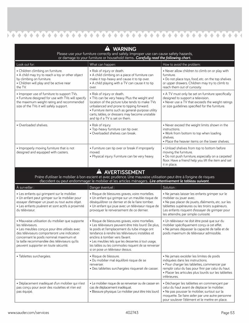
AVERTISSEMENTPrière d’utiliser le mobilier à bon escient et avec prudence. Une mauvaise utilisation peut être à l’origine de risques
d’accident ou peut endommager le mobilier et les articles ménagers. Lire attentivement le tableau suivant.À surveiller : Danger éventuel : Solution :
• Les enfants qui grimpent sur le mobilier.• Un enfant peut grimper sur le mobilier pour essayer d’attraper un jouet ou tout autre objet.• Les enfants jouèrent et sont actifs à proximité du téléviseur.
• Risque de blessures graves, voire mortelles.• Un enfant qui grimpe sur un meuble risque de déséquilibrer ce dernier et de le faire tomber.• Un enfant qui joue avec un téléviseur risque de provoquer le renversement de ce dernier.
• Ne jamais laisser les enfants grimper sur le mobilier ou jouer avec.• Ne pas placer de jouets, d’aliments, etc. sur les tablettes supérieures ou les tiroirs supérieurs. Les enfants risquent d’essayer de grimper pour les atteindre, par simple curiosité.
• Mauvaise utilisation du mobilier que supporte les téléviseurs.• Les meubles conçus pour être utilisés avec des téléviseurs comporteront une indication concernant le poids nominal maximum et la taille recommandée des téléviseurs qu’ils peuvent supporter en toute sécurité.
• Risque de blessures graves, voire mortelles.• Les téléviseurs peuvent être très lourd. De plus, le poids et l’emplacement du tube image ont tendance à rendre les téléviseurs instables et enclins à tomber vers l’avant.• Les meubles tels que les dessertes à tout usage, les tables ou les commodes risquent de se renverser si on pose un téléviseur dessus.
• Un téléviseur ne doit être posé que sur du mobilier spécifi quement conçu à cet eff et.• Ne jamais dépasser la capacité de taille et de poids maximum de téléviseur admissible.
• Tablettes surchargées. • Risque de blessure.• Du mobilier mal équilibré risque de se renverser.• Des tablettes surchargées risquerait de casser.
• Ne jamais excéder les limites de poids indiquées dans les instructions.• Pour charger les tablettes, commencer par remplir celui du bas pour fi nir par celui du haut.• Placer les articules plus lourds sur les tablettes inférieures.
• Déplacement inadéquat d’un mobilier qui n’est pas conçu pour avoir des roulettes et n’en est pas équipé.
• Le mobilier risque de se renverser ou de casser en cas de déplacement inadéquat. • Blessure physique. Le mobilier peut être très lourd.
• Décharger les tablettes en commençant par celui du haut avant de déplacer le mobilier.• Ne pas pousser le mobilier, surtout sur la moquette. Se faire aider par une autre personne pour soulever l’élément et le mettre en place.
WARNINGPlease use your furniture correctly and safely. Improper use can cause safety hazards,or damage to your furniture or household items. Carefully read the following chart.
Look out for: What can happen: How to avoid the problem:
• Children climbing on furniture.• A child may try to reach a toy or other object by climbing on furniture.• Children will play and be active near the TV.
• Risk of injury or death.• A child climbing on a piece of furniture can make it top-heavy and cause it to tip over.• A child playing with a TV can cause it to tip over.
• Never allow children to climb on or play with furniture.• Do not place toys, food, etc. on the top shelves or upper drawers. Children may try to climb to reach them out of curiosity.
• Improper use of furniture to support TVs.• Furniture designed for use with TVs will specify the maximum weight rating and recommended size of the TVs it will safely support.
• Risk of injury or death.• TVs can be very heavy. Plus the weight and location of the picture tube tends to make TVs unbalanced and prone to tipping forward.• Furniture items such as general-purpose utility carts, tables, or dressers may become unstable and tip if a TV is set on them.
• A TV must only be set on furniture specifi cally designed to support a television.• Never use a TV that exceeds the weight ratings or size guidelines specifi ed for the furniture.
• Overloaded shelves. • Risk of injury.• Top-heavy furniture can tip over.• Overloaded shelves can break.
• Never exceed the weight limits shown in the instructions.• Work from bottom to top when loading shelves.• Place the heavier items on the lower shelves.
• Improperly moving furniture that is not designed and equipped with casters.
• Furniture can tip over or break if improperly moved.• Physical injury. Furniture can be very heavy.
• Unload shelves from top to bottom before moving the furniture.• Do not push furniture, especially on a carpeted fl oor. Have a friend help you lift the item and set it in place.
402743 www.sauder.com/servicesPage 54
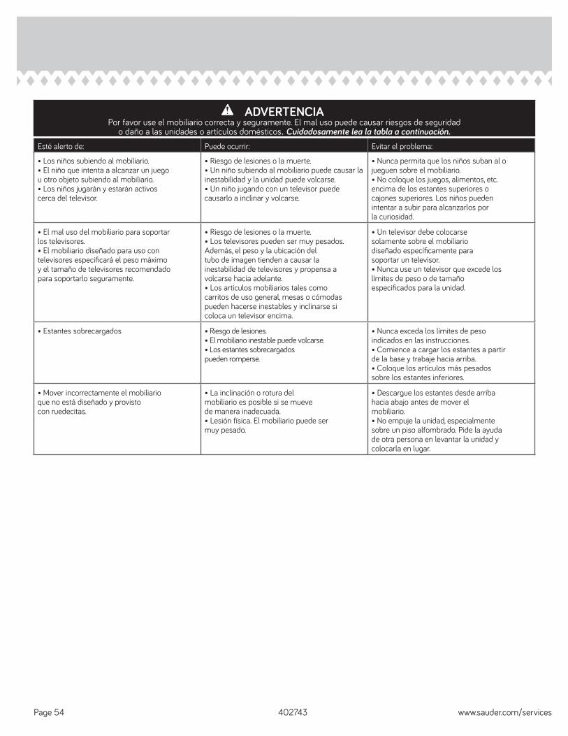
ADVERTENCIAPor favor use el mobiliario correcta y seguramente. El mal uso puede causar riesgos de seguridad
o daño a las unidades o artículos domésticos. Cuidadosamente lea la tabla a continuación.Esté alerto de: Puede ocurrir: Evitar el problema:
• Los niños subiendo al mobiliario.• El niño que intenta a alcanzar un juegou otro objeto subiendo al mobiliario.• Los niños jugarán y estarán activoscerca del televisor.
• Riesgo de lesiones o la muerte.• Un niño subiendo al mobiliario puede causar la inestabilidad y la unidad puede volcarse.• Un niño jugando con un televisor puede causarlo a inclinar y volcarse.
• Nunca permita que los niños suban al ojueguen sobre el mobiliario.• No coloque los juegos, alimentos, etc.encima de los estantes superiores ocajones superiores. Los niños puedenintentar a subir para alcanzarlos porla curiosidad.
• El mal uso del mobiliario para soportarlos televisores.• El mobiliario diseñado para uso contelevisores especifi cará el peso máximoy el tamaño de televisores recomendadopara soportarlo seguramente.
• Riesgo de lesiones o la muerte.• Los televisores pueden ser muy pesados. Además, el peso y la ubicación deltubo de imagen tienden a causar lainestabilidad de televisores y propensa avolcarse hacia adelante.• Los artículos mobiliarios tales comocarritos de uso general, mesas o cómodaspueden hacerse inestables y inclinarse sicoloca un televisor encima.
• Un televisor debe colocarsesolamente sobre el mobiliariodiseñado específi camente parasoportar un televisor.• Nunca use un televisor que excede loslímites de peso o de tamañoespecifi cados para la unidad.
• Estantes sobrecargados • Riesgo de lesiones.• El mobiliario inestable puede volcarse.• Los estantes sobrecargadospueden romperse.
• Nunca exceda los límites de pesoindicados en las instrucciones.• Comience a cargar los estantes a partirde la base y trabaje hacia arriba.• Coloque los artículos más pesadossobre los estantes inferiores.
• Mover incorrectamente el mobiliarioque no está diseñado y provistocon ruedecitas.
• La inclinación o rotura delmobiliario es posible si se muevede manera inadecuada.• Lesión física. El mobiliario puede sermuy pesado.
• Descargue los estantes desde arribahacia abajo antes de mover elmobiliario.• No empuje la unidad, especialmentesobre un piso alfombrado. Pide la ayudade otra persona en levantar la unidad ycolocarla en lugar.
1. Sauder Woodworking Co. (Sauder®) provee cobertura de garantía limitada al comprador original de este producto por un período de cinco años, a partir de la fecha de compra, contra defectos en los materiales o de mano de obra en los componentes de muebles Sauder. Como es utilizado en esta Garantía, “defecto” signifi ca imperfecciones en los componentes que de manera fundamental afecta la utilidad del producto. Esta Garantía le permite a usted ciertos derechos legales, y usted también podría poseer otros derechos adicionales, los cuales varían de estado a estado.2. No hay cobertura de garantía para defectos o estados que resulten del incumplimiento en seguir las instrucciones, la información o las advertencias sobre el ensamblaje del producto; del uso incorrecto o maltrato, del daño intencional, incendio, inundación, cambio o modifi cación del producto; o de la utilización del producto de manera contradictoria con el uso para el cual fue fabricado, ni por ningún estado que resulte del mantenimiento, limpieza o cuidado incorrecto o inadecuado. Tampoco no hay cobertura de garantía para los productos rentados o para cualesquiera productos comprados “de uso” o “como está”, en una venta de bienes embargados o en una venta por salirse del negocio, o comprados a un liquidador.3. Como un recurso exclusivo bajo esta Garantía, Sauder (sólo a su opción) reparará o reemplazará cualquier componente defectuoso de mueble. Sauder puede requerir una confi rmación independiente de un defecto reclamado y una prueba de compra. Las piezas de repuesto serán garantizadas solamente por el período de tiempo que queda de la Garantía original. SAUDER NO TENDRÁ RESPONSABILIDAD por NINGÚN DAÑO INCIDENTAL O CONSECUENTE DE NINGÚN TIPO y todos dichos daños SE EXCLUYEN DE ESTA GARANTÍA, tales como pérdida de uso, desensamblaje, transportación, trabajo o daño a la propiedad en o cerca del producto. Algunos estados no permiten la exclusión o limitación de daños incidentales o consecuentes, en tales instancias la limitación o exclusión antes mencionada podría no ser aplicable a usted.
4. Esta Garantía sólo es aplicable a defectos garantizados que primeramente surjan y se informen a Sauder dentro del período de cobertura de garantía. La Garantía no puede ser transferida a propietarios o usuarios subsiguientes del producto, y ésta será inmediatamente invalidada en el caso que el producto sea revendido, transferido, arrendado o rentado a cualquier tercero u otra persona que no sea el comprador original.5. NO HAY OTRA GARANTÍA APLICABLE A ESTE PRODUCTO. Bajo las leyes de ciertos estados, pueden no haber garantías implícitas de Sauder y se hace renuncia de responsabilidad de todas las garantías implícitas donde lo permita la ley, INCLUYENDO CUALQUIER GARANTÍA IMPLÍCITA DE MERCANTIBILIDAD O DE APTITUD PARA UN PROPÓSITO EN PARTICULAR. EN LA MEDIDA CUALQUIER GARANTÍA IMPLÍCITA ES APLICABLE, CUALESQUIERA GARANTÍAS IMPLÍCITAS, INCLUYENDO AQUELLA DE MERCANTIBILIDAD O DE APTITUD PARA UN PROPÓSITO EN PARTICULAR, SE LIMITAN EN DURACIÓN HASTA LA DURACIÓN DE ESTA GARANTÍA IMPLÍCITA o hasta el periodo mínimo permitido por la ley, la que sea más corta. Algunos estados no permiten limitaciones en cuanto a la duración de una garantía implícita, por eso la limitación arriba citada pueda no ser aplicable a usted.6. Para solicitud de información o reclamación de Garantía, por favor, visite nuestro sitio Web www.sauder.com. Usted también puede contactar a Sauder llamando al 1-800-523-3987. Sauder puede solicitar que las reclamaciones sean presentadas por escrito a Sauder Woodworking Co., 502 Middle Street, Archbold, OH 43502 EE.UU. Por favor incluya su recibo de venta u otra prueba de compra y una descripción detallada del defecto del producto.
GARANTÍA LIMITADA DE 5 AÑOS
1. Sauder Woodworking Co. (Sauder®) off re une couverture de garantie limitée à l’acheteur initial du présent produit pendant une période de cinq ans à compter de la date d’achat contre tout défaut de matériaux ou de fabrication des composantes de mobilier Sauder. Le mot « défaut », tel qu’il est utilisé sous les termes de la présente garantie, comprend les imperfections des pièces qui empêchent substantiellement l’utilisation du produit. La présente garantie vous donne des droits légaux spécifi ques et il est possible que vous ayez des droits supplémentaires variant d’État en État ou de province en province.2. La présente garantie ne saurait couvrir les défauts ou conditions qui surviendraient à la suite du non respect des instructions, informations ou mises en garde de montage, d’une mauvaise utilisation ou d’un abus, d’un dommage intentionnel, d’un incendie, d’une inondation, d’une altération ou modifi cation du produit, d’une utilisation du produit allant à l’encontre de son usage prévu, ni aucune condition résultant d’une maintenance, d’un nettoyage ou d’un entretien inappropriés ou inadéquats. De plus, il n’existe aucune garantie pour les produits loués ou tous les produits achetés « d’occasion » ou « en l’état », dans le cadre d’une vente aux enchères ou de solde pour cessation de commerce, ou auprès d’un liquidateur.3. En tant que recours exclusif en vertu de la présente garantie, Sauder réparera ou remplacera (sur sa seule décision) toute composante de mobilier défectueuse. Sauder peut exiger une confi rmation indépendante du défaut revendiqué ainsi qu’une preuve d’achat. Les pièces de rechange seront garanties uniquement pendant la période restante de la garantie originale. SAUDER NE SERA EN AUCUN CAS RESPONSABLE de TOUT DOMMAGE ACCESSOIRE OU CONSÉCUTIF DE TOUTE SORTE et lesdits dommages sont EXCLUS DE LA PRÉSENTE GARANTIE, à savoir perte d’utilisation, démontage, transport, main d’ceuvre ou dommages matériels sur ou à proximité du produit. Certains États ou provinces ne permettant pas l’exclusion ou la limite aux responsabilités pour dommages accidentels ou consécutifs, la limite ou l’exclusion ci-dessus peut ne pas être applicable.
4. La présente garantie ne s’applique qu’aux défauts garantis qui se produisent pour la première fois et qui sont signalés à Sauder dans les limites de ouverture de la garantie. La garantie ne peut pas être transférée à des propriétaires ou utilisateurs subséquents du produit, et sera immédiatement invalidée dans le cas où le produit est revendu, transféré, loué sous bail ou loué à une tierce partie ou personne autre que l’acheteur original.5. IL N’EXISTE AUCUNE AUTRE GARANTIE EN VIGUEUR POUR LE PRÉSENT PRODUIT. En vertu des lois de certains États ou provinces, il ne peut y avoir de garanties implicites de la part de Sauder et toutes les garanties implicites, Y COMPRIS TOUTE GARANTIE IMPLICITE DE COMMERCIABILITÉ OU D’ADAPTATION À UN USAGE PARTICULIER sont déclinées partout où la loi l’autorise. DANS LA MESURE OÙ TOUTE GARANTIE IMPLICITE EST APPLICABLE, TOUTE GARANTIE IMPLICITE, Y COMPRIS TOUTE GARANTIE DE COMMERCIABILITÉ OU D’ADAPTATION À UN USAGE PARTICULIER, EST LIMITÉE À LA DURÉE DE LA PRÉSENTE GARANTIE EXPRESSE ou à la période minimum autorisée par la loi, la période la plus courte étant retenue. Certains États ne permettant pas que des limites soient imposées quant à la durée d’une garantie implicite, la limite ci-dessus peut donc ne pas être applicable.6. Pour toute question concernant la garantie ou toute demande de réclamation, consulter le site Web www.sauder.com. Il est également possible de contacter Sauder en composant le 1-800-523-3987. Sauder peut exiger de soumettre les demandes de réclamation sous garantie par écrit à Sauder Woodworking Co., 502 Middle Street, Archbold, OH 43502 USA. Veuillez joindre votre ticket de caisse ou toute autre preuve d’achat ainsi qu’une description spécifi que du défaut de produit.
GARANTIE LIMITÉE DE 5 ANS
1. Sauder Woodworking Co. (Sauder®) provides limited warranty coverage to the original purchaser of this product for a period of fi ve years from the date of purchase against defects in materials or workmanship of Sauder furniture components. As used in this Warranty, “defect” means imperfections in components which substantially impair the utility of the product. This Warranty gives you specifi c legal rights, and you may also have other rights which vary from state to state.2. There is no warranty coverage for defects or conditions that result from the failure to follow product assembly instructions, information or warnings, misuse or abuse, intentional damage, fi re, fl ood, alteration or modifi cation of the product, or use of the product in a manner inconsistent with its intended use, nor any condition resulting from incorrect or inadequate maintenance, cleaning, or care. There is also no warranty coverage for rented products or any products purchased “used” or “as is”, at a distress or going-out-of business sale, or from a liquidator.3. As the exclusive remedy under this Warranty, Sauder will (at its sole option) repair or replace any defective furniture component. Sauder may require independent confi rmation of the claimed defect and proof of purchase. Replacement parts will be warranted for only the remaining period of the original Warranty. SAUDER SHALL HAVE NO LIABILITY for ANY INCIDENTAL OR CONSEQUENTIAL DAMAGES OF ANY KIND and all such damages are EXCLUDED FROM THIS WARRANTY, such as loss of use, disassembly, transportation, labor or damage to property on or near the product. Some states do not allow the exclusion or limitation of incidental or consequential damages, so the above limitation or exclusion may not apply to you.
4. This Warranty applies only to warranted defects that fi rst arise and are reported to Sauder within the warranty coverage period. The Warranty cannot be transferred to subsequent owners or users of the product, and it shall be immediately void in the event the product is resold, transferred, leased or rented to any third party or person other than the original purchaser.5. THERE ARE NO OTHER WARRANTIES APPLICABLE TO THIS PRODUCT. Under the laws of certain states, there may be no implied warranties from Sauder and all implied warranties, INCLUDING ANY IMPLIED WARRANTY OF MERCHANTABILITY OR FITNESS FOR A PARTICULAR PURPOSE are disclaimed where allowed by law. TO THE EXTENT ANY IMPLIED WARRANTIES ARE APPLICABLE, ANY IMPLIED WARRANTIES, INCLUDING ANY IMPLIED WARRANTY OF MERCHANTABILITY OR FITNESS FOR A PARTICULAR PURPOSE, ARE LIMITED IN DURATION TO THE DURATION OF THIS EXPRESS WARRANTY or the minimum period allowed by law, whichever is shorter. Some states do not allow limitations on how long an implied Warranty lasts, so the above limitation may not apply to you.6. For Warranty inquiries or claims, please visit our website www.sauder.com.You can also contact Sauder at 1-800-523-3987. Sauder may require Warranty claims to be submitted in writing to Sauder Woodworking Co., 502 Middle Street, Archbold, OH 43502 USA. Please include your sales receipt or other proof of purchase and a specifi c description of the product defect.
5-YEAR LIMITED WARRANTY
402743www.sauder.com/services Page 55

Register your new product online
For immediate service, our website is available 24 hours per day, seven days per week, to order replacement parts, access assembly tips, register your product and view Sauder products. www.sauder.comCustomer Services in United States and Canada Monday through Friday – 9 a.m. to 5:30 p.m. ET (except holidays) 1-800-523-3987
Dear Valued Customer:
Thanks so much for choosing Sauder® furniture. I hope the purchase and assembly process was a positive experience and you feel good about the furniture you just built. If you need assistance or want to learn more, please contact our award-winning, Ohio-based customer service team at 800-523-3987 or Sauder.com.
My grandfather, Erie Sauder, founded the company in 1934 and later invented and patented the fi rst commercially successful ready-to-assemble tables. We strive to hold true to his core values of innovation, integrity, servanthood and stewardship.
Sauder products are made with environmentally responsible materials and world-class manufacturing processes. Our 2,000+ dedicated employees in Archbold, Ohio, along with our global manufacturing partners, are committed to providing you furniture with great value, style and quality.
From our family to you. Enjoy!
Kevin J. SauderPresident/CEO
So, how did it go? Set a world record for speed? Feeling good about yourself? Nice. Get social with it on any of these quality share sites.
General Conformity Certifi cate1. This certifi cate applies to the Sauder Woodworking Product identifi ed by this Instruction Book.2. This certifi cate applies to compliance of this product with the CPSC Ban on Lead-Containing Paint (16 CFR 1303).3. This product is manufactured by: Sauder Woodworking Company 502 Middle St. Archbold, OH 43502 419-446-27114. Date of Manufacture: __________________________
And don’t forget to rate and review your piece at Sauder.com in the product detail page.