Embed Size (px)
Citation preview
STANLEY CONSULTANTS, INC. 1 I-40, BELLEMONT TO WINONA
INITIAL DESIGN CONCEPT REPORT
1.0 Introduction
1.1 Foreword
Interstate 40 (I-40) is one of the nation's principal east-west highways. The intersection of I-40 and I-17 in Flagstaff makes I-40 part of critical trade and truck routes linking Mexican markets with Arizona's major urban centers and markets of New Mexico, Utah, and northern California. In addition to accommodating rapidly increasing local traffic, I-40 supports recreational traffic destined for the Grand Canyon, national forests, the City of Flagstaff, and Native American communities in northern Arizona.
The Arizona Department of Transportation (ADOT), in partnership with the Federal Highway Administration (FHWA), has initiated a design concept study and environmental studies to evaluate the proposed improvements to I-40 in Coconino County, Arizona. The study area begins west of the I-40/Bellemont Traffic Interchange (TI) at milepost (MP) 183.0 and extends east to MP 214.0, east of the Winona TI. The study area is located within ADOT's Flagstaff District.
Much of existing I-40 is located on easements from the Coconino National Forest (CNF), and, to a lesser extent, the Kaibab National Forest (KNF), which manage the majority of the land adjacent to I-40 in the project area. Privately-owned property includes land adjacent to the existing Bellemont, West Flagstaff, Flagstaff Ranch, Butler, Country Club, Cosnino, and Winona TIs, as well as properties between MP 191.5 and MP 203.0.
The existing roadway is a four-lane divided facility that traverses rolling terrain. The horizontal and vertical alignments follow relatively steep grades from MP 188.5 to MP 190.0 (Arizona Divide), MP 191.7 to MP 193.0 (West Flagstaff TI to Flagstaff Ranch TI), and MP 194.2 to MP 194.9 (west of I-40/I-17 system TI). The roadway between MP 183.0 and MP 193.0 and between MP 203.0 and MP 214.0 is classified as rural; between MP 193.0 and MP 203.0, it is classified as urban/fringe urban.
The steeper rolling terrain along the corridor presents challenges to widening the I-40 in terms of existing alignments with steep grades in deep rock cuts and narrow cross sections. In addition, severe winter weather can cause closures of I-40 that result in lengthy travel delays along the route.
The study will provide a long-range implementation strategy that will guide future decisions regarding the interim and ultimate improvements required to meet the capacity and operational needs of the traveling public over the next 30 years. An environmental assessment (EA) is being developed in concert with this design concept study. Implementation of the study recommendations will depend on funding availability and prioritization of roadway construction projects.
1.2 Purpose of the Project
The purpose of this project is to improve operations and reduce congestion by adding capacity to I-40 from west of the Bellemont TI to east of the Winona TI. The study will develop and evaluate feasible alternatives to meet the capacity needs for the design year 2040, as well as interim (short-term) improvements. This study will identify a range of improvements, such as the widening of I-40, redesigned interchanges, and proposed new interchanges, based on the results of preliminary engineering and environmental technical studies. The results of the engineering analysis are documented in this Design Concept Report (DCR), and the results of the
environmental analyses will be presented in an EA prepared to meet the requirements of the National Environmental Policy Act (NEPA) of 1969.
1.3 Description of the Project
Figure 1 – Location Map
The study area begins on I-40 at approximately MP 183.0, west of the existing Bellemont TI, and extends east to approximately MP 214.0, east of the Winona TI. The project limits also include the northern terminus of I-17 at the I-40 system interchange and all of the ramps associated with the system interchange. A location map detailing the study limits and the surrounding area is shown on Figure 1. A vicinity map is shown on Figure 2.
The project will add one lane in each direction from MP 183.6 to MP 208.4, plus auxiliary lanes between the Flagstaff Ranch TI and new Woody Mountain TI (MP 192.6 to MP 193.4) and between the I-40/I-17 system interchange and Butler TI (MP 195.6 to MP 198.2). At the western project limit, the added lanes will begin at the new Camp Navajo TI ramps. At the eastern widening limit (MP 208.4), the proposed lanes will transition to match into the existing I-40 roadway which has two lanes in each direction. Interchange improvements are recommended at several existing TIs, and four new interchanges are proposed.
Beginning at the western end, the project extends east through portions of:
Township (T) 22 North (N), Range (R) 5 East (E), Sections 35 and 36
T21N, R5E, Sections 1 and 2
T21N, R6E, Sections 6, 7, 8, 15, 16, 17, 22, 23, and 24
T21N, R7E, Sections 13, 14, 19, 22, 23, 27, 28, 29, and 30
T21N, R8E, Sections 7, 8, 9, 10, 11, 13, and 14
T21N, R9E, Sections 13, 14, 15, 16, 17, 18, and 24
T21N, R10E, Sections 19, 28, 29, 30, 33, 34, and 35
These references are identified on the Bellemont, Flagstaff West, Flagstaff East, Winona, and Angell, Arizona, US Geological Survey (USGS) 7.5-minute topographic series.
STANLEY CONSULTANTS, INC. 2 I-40, BELLEMONT TO WINONA
INITIAL DESIGN CONCEPT REPORT
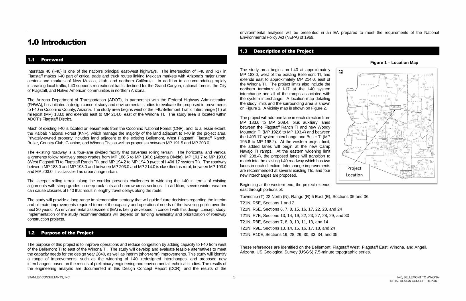
Figure 2 – Vicinity Map
The project begins at approximately 6850 feet elevation at its western end in rolling terrain west of the Bellemont Flat in Coconino County. Extending southeast, the project ascends gradually over the Arizona Divide and reaches a maximum elevation of 7335 feet at approximately MP 190. Along the western 11 miles of the project, I-40 climbs and descends as it winds around the base of the San Francisco Peaks into the Flagstaff city limits. Landform throughout the corridor is typical of the Colorado Plateau region of Arizona. The I-40 alignment passes through a number of flat meadows within the corridor. The vegetation is a mix of ponderosa and oak woodlands
1.4 Project Objectives
The primary objectives of this study include evaluating the addition of mainline capacity to accommodate anticipated future traffic volumes from growth and planned development. The addition of capacity will help ADOT meet its long-range goal of providing an improved roadway on one of the major west-to-east corridors in the state, as well as improved operations through Flagstaff and the surrounding communities. Widening the roadway is anticipated to reduce congestion and travel times, as well as provide greater flexibility for ADOT to manage incidents and facilitate maintenance.
1.4.1 Public Involvement
Community members were provided an opportunity to comment and take part in the early development of this project through a public involvement process that to date has included agency and public scoping meetings, agency and public information meetings, and a presentation of project data and progress on a project web site.
1.4.2 Scoping Meetings
ADOT initiated the I-40 design concept study by conducting scoping meetings with federal, state, county, and local agency representatives and the public. An agency scoping meeting for the project was held on July 14, 2009, at the Radisson Woodlands Hotel, 1175 North Route 66, in Flagstaff, Arizona. A public scoping meeting for the project was held on the same date at the same venue later that evening. The purpose of these meetings was to provide a general overview of the study area and to obtain input from the agency representatives, business people, and area residents about the existing roadway and surrounding area. Participants, who included representatives from the agencies listed below, were invited to identify the issues, concerns, and opportunities (ICOs) that should be addressed during the development and evaluation of alternatives in the DCR and EA.
ADOT Flagstaff United School District
AGFD FHWA
City of Flagstaff KNF
Coconino County National Park Service, Flagstaff Area Monuments
CNF Department of Public Safety, District 2
Flagstaff Metropolitan Planning Organization (FMPO)
US Army Corps of Engineers (COE)
STANLEY CONSULTANTS, INC. 3 I-40, BELLEMONT TO WINONA
INITIAL DESIGN CONCEPT REPORT
The study team prepared and distributed an informational postcard inviting the public to attend the scoping meeting. The postcard was mailed on June 26, 2009, to approximately 13,200 individuals on the mailing list, which included property owners within 0.5 mile of I-40 between the study limits, as well as elected officials and key stakeholders identified as having an interest in area transportation studies. Twenty-two community members signed in at the meeting. Eight comment forms were completed and two letters and twelve e-mails were received.
The following ICOs were identified during the agency and public scoping meeting. Other comments were received that identified a broad-range of issues that are not within the scope of this project and will not be addressed by the study. Details of each meeting and comments received are presented in the October 2009 Scoping Summary for the project.
1.4.2.1 Design Issues, Concerns, and Opportunities
The safe flow of traffic through the corridor is a major concern of both the agencies and the general public. Design ICOs identified through the scoping process include the following:
Construct additional travel lane in each direction to maintain the flow of traffic.
Construct new traffic interchanges along the corridor where future development requires access to I-40.
Address traffic operations at the existing Bellemont TI.
Construct sound walls along residential developments.
Consider asphalt recycling as part the construction efforts.
Consider the use of highway lighting to improve visibility for the interstate traffic, but do not affect the nearby observatories.
Consider an additional crossing over I-40 for Camp Navajo projected development.
Use rubberized pavement to reduce noise impacts along this corridor.
Consider constructing wider emergency pull-offs/chain-up areas.
1.4.2.2 Social and Economic Issues, Concerns, and Opportunities
Social and economic ICOs identified through the scoping process include the following:
Consider impacts to Arizona State Lands property in the selection of the proposed right-of-way (R/W) required.
Consider the future land use and growth along the corridor.
Consider the effects of commuters to Flagstaff from the projected growth outside the project study limits.
Evaluate and improve the signage to the Walnut Canyon National Monument.
Evaluate how improvements along I-40 will impact development growth along this corridor.
Coordinate with the City of Flagstaff, US Forest Service, and other non-profit organizations about existing and proposed trail locations.
1.4.2.3 Environmental Issues, Concerns, and Opportunities
Environmental ICOs identified through the scoping process include the following:
Coordinate with Arizona Game & Fish Department (AGFD) about wildlife crossings and corridor connectivity.
Minimize wildlife and environmental impacts during all phases of the design and construction process.
Minimize impacts to visual quality and tree mortality.
Consider fuel reduction actions, vegetation management, and reduction of invasive weeds.
Minimize impacts on permanent, seasonal, and ephemeral waters in the area.
1.4.3 Information Meetings
Agency and public information meetings were held on August 5, 2010, to provide an update on the I-40 study.
The agency information meeting was held on August 5, 2010, at the Radisson Woodlands Hotel, 1175 W. Route 66, in Flagstaff, Arizona. The purpose of the meeting was to provide agency representatives with an update on study information and to receive input on the study alternatives and preliminary recommendations. Thirty-three individuals attended this meeting.
The agency information meeting began at 1:30 p.m. and included a formal presentation, followed by a discussion session. The presentation provided an overview of agency roles, the study purpose and objectives, engineering elements, preliminary design concepts, study schedule and process, and environmental studies to be completed. Roll plots identifying the study area and informational boards were also available for agency representatives to view.
Additionally, ADOT conducted a separate videoconference meeting with representatives from Northern Arizona University (NAU) and FMPO on August 11, 2010, at 3:00 p.m. at the ADOT Flagstaff/Phoenix video conference facilities; ADOT Flagstaff District Office, Main Conference Room, 1801 S. Milton Road, in Flagstaff, Arizona, and the ADOT Phoenix Administration Building, Green Room, 206 S. 17th Avenue, in Phoenix, Arizona. A separate meeting was conducted because NAU representatives had a scheduling conflict with the August 5 meeting. The same information in the format from the agency information meeting was presented to the NAU representatives.
Following the presentation, each agency representative was asked for input on the study during the discussion session. The ADOT study team contact information and comment forms were provided for agency representatives to continue providing input. The presentation, comments and responses from the agency information meeting and the separate videoconference meeting with NAU are documented in the Agency Information Meeting Summary, November 2010.
The public information meeting was held from 6:00 p.m. to 8:00 p.m. on August 5, 2010, in the same location as the agency information meeting. The meeting included a formal presentation, followed by a discussion session with meeting attendees. Approximately thirty individuals attended the public information meeting. The presentation provided an overview of the study purpose and objectives as well as information on proposed improvements, alternatives, and environmental status. In addition, the study schedule was reviewed. The presentation also provided contact information for meeting attendees to provide input. Informational boards and roll plots identifying the proposed improvements and alternatives were also available for the public to view.
After the presentation, meeting attendees were given the opportunity to provide input and comments, as well as the opportunity to highlight issues of importance. The presentation, verbal questions and comments received during the meeting, and the ADOT study team’s summarized responses are provided in the Public Information Meeting Summary, November 2010.
STANLEY CONSULTANTS, INC. 4 I-40, BELLEMONT TO WINONA
INITIAL DESIGN CONCEPT REPORT
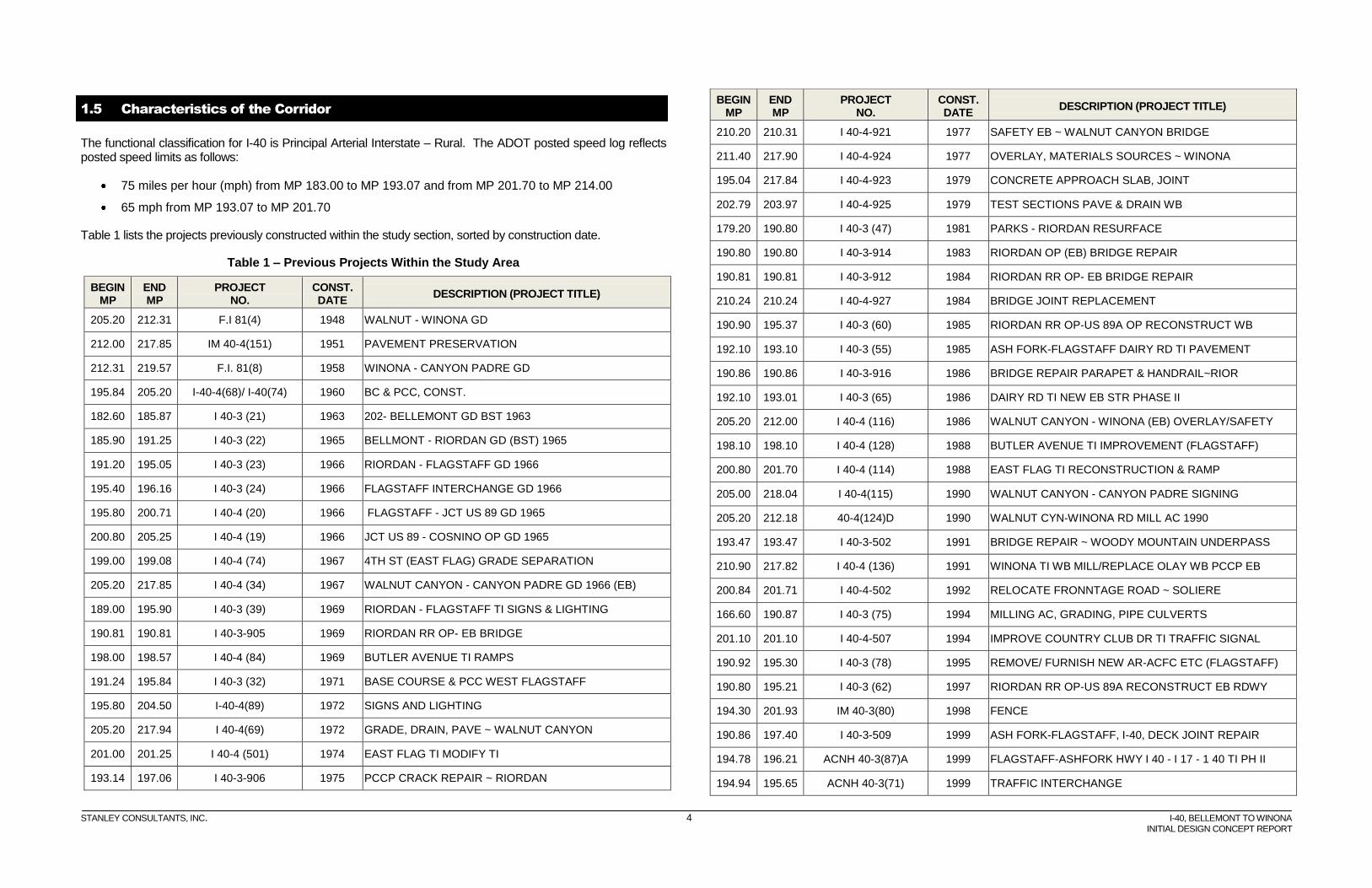
1.5 Characteristics of the Corridor
The functional classification for I-40 is Principal Arterial Interstate – Rural. The ADOT posted speed log reflects posted speed limits as follows:
75 miles per hour (mph) from MP 183.00 to MP 193.07 and from MP 201.70 to MP 214.00
65 mph from MP 193.07 to MP 201.70
Table 1 lists the projects previously constructed within the study section, sorted by construction date.
Table 1 – Previous Projects Within the Study Area
BEGIN MP
END MP
PROJECT NO.
CONST. DATE
DESCRIPTION (PROJECT TITLE)
205.20 212.31 F.I 81(4) 1948 WALNUT - WINONA GD
212.00 217.85 IM 40-4(151) 1951 PAVEMENT PRESERVATION
212.31 219.57 F.I. 81(8) 1958 WINONA - CANYON PADRE GD
195.84 205.20 I-40-4(68)/ I-40(74) 1960 BC & PCC, CONST.
182.60 185.87 I 40-3 (21) 1963 202- BELLEMONT GD BST 1963
185.90 191.25 I 40-3 (22) 1965 BELLMONT - RIORDAN GD (BST) 1965
191.20 195.05 I 40-3 (23) 1966 RIORDAN - FLAGSTAFF GD 1966
195.40 196.16 I 40-3 (24) 1966 FLAGSTAFF INTERCHANGE GD 1966
195.80 200.71 I 40-4 (20) 1966 FLAGSTAFF - JCT US 89 GD 1965
200.80 205.25 I 40-4 (19) 1966 JCT US 89 - COSNINO OP GD 1965
199.00 199.08 I 40-4 (74) 1967 4TH ST (EAST FLAG) GRADE SEPARATION
205.20 217.85 I 40-4 (34) 1967 WALNUT CANYON - CANYON PADRE GD 1966 (EB)
189.00 195.90 I 40-3 (39) 1969 RIORDAN - FLAGSTAFF TI SIGNS & LIGHTING
190.81 190.81 I 40-3-905 1969 RIORDAN RR OP- EB BRIDGE
198.00 198.57 I 40-4 (84) 1969 BUTLER AVENUE TI RAMPS
191.24 195.84 I 40-3 (32) 1971 BASE COURSE & PCC WEST FLAGSTAFF
195.80 204.50 I-40-4(89) 1972 SIGNS AND LIGHTING
205.20 217.94 I 40-4(69) 1972 GRADE, DRAIN, PAVE ~ WALNUT CANYON
201.00 201.25 I 40-4 (501) 1974 EAST FLAG TI MODIFY TI
193.14 197.06 I 40-3-906 1975 PCCP CRACK REPAIR ~ RIORDAN
BEGIN MP
END MP
PROJECT NO.
CONST. DATE
DESCRIPTION (PROJECT TITLE)
210.20 210.31 I 40-4-921 1977 SAFETY EB ~ WALNUT CANYON BRIDGE
211.40 217.90 I 40-4-924 1977 OVERLAY, MATERIALS SOURCES ~ WINONA
195.04 217.84 I 40-4-923 1979 CONCRETE APPROACH SLAB, JOINT
202.79 203.97 I 40-4-925 1979 TEST SECTIONS PAVE & DRAIN WB
179.20 190.80 I 40-3 (47) 1981 PARKS - RIORDAN RESURFACE
190.80 190.80 I 40-3-914 1983 RIORDAN OP (EB) BRIDGE REPAIR
190.81 190.81 I 40-3-912 1984 RIORDAN RR OP- EB BRIDGE REPAIR
210.24 210.24 I 40-4-927 1984 BRIDGE JOINT REPLACEMENT
190.90 195.37 I 40-3 (60) 1985 RIORDAN RR OP-US 89A OP RECONSTRUCT WB
192.10 193.10 I 40-3 (55) 1985 ASH FORK-FLAGSTAFF DAIRY RD TI PAVEMENT
190.86 190.86 I 40-3-916 1986 BRIDGE REPAIR PARAPET & HANDRAIL~RIOR
192.10 193.01 I 40-3 (65) 1986 DAIRY RD TI NEW EB STR PHASE II
205.20 212.00 I 40-4 (116) 1986 WALNUT CANYON - WINONA (EB) OVERLAY/SAFETY
198.10 198.10 I 40-4 (128) 1988 BUTLER AVENUE TI IMPROVEMENT (FLAGSTAFF)
200.80 201.70 I 40-4 (114) 1988 EAST FLAG TI RECONSTRUCTION & RAMP
205.00 218.04 I 40-4(115) 1990 WALNUT CANYON - CANYON PADRE SIGNING
205.20 212.18 40-4(124)D 1990 WALNUT CYN-WINONA RD MILL AC 1990
193.47 193.47 I 40-3-502 1991 BRIDGE REPAIR ~ WOODY MOUNTAIN UNDERPASS
210.90 217.82 I 40-4 (136) 1991 WINONA TI WB MILL/REPLACE OLAY WB PCCP EB
200.84 201.71 I 40-4-502 1992 RELOCATE FRONNTAGE ROAD ~ SOLIERE
166.60 190.87 I 40-3 (75) 1994 MILLING AC, GRADING, PIPE CULVERTS
201.10 201.10 I 40-4-507 1994 IMPROVE COUNTRY CLUB DR TI TRAFFIC SIGNAL
190.92 195.30 I 40-3 (78) 1995 REMOVE/ FURNISH NEW AR-ACFC ETC (FLAGSTAFF)
190.80 195.21 I 40-3 (62) 1997 RIORDAN RR OP-US 89A RECONSTRUCT EB RDWY
194.30 201.93 IM 40-3(80) 1998 FENCE
190.86 197.40 I 40-3-509 1999 ASH FORK-FLAGSTAFF, I-40, DECK JOINT REPAIR
194.78 196.21 ACNH 40-3(87)A 1999 FLAGSTAFF-ASHFORK HWY I 40 - I 17 - 1 40 TI PH II
194.94 195.65 ACNH 40-3(71) 1999 TRAFFIC INTERCHANGE
STANLEY CONSULTANTS, INC. 5 I-40, BELLEMONT TO WINONA
INITIAL DESIGN CONCEPT REPORT
BEGIN MP
END MP
PROJECT NO.
CONST. DATE
DESCRIPTION (PROJECT TITLE)
205.20 212.02 40-4(152) 1999 ARAC, AR-ACFC, WIDEN BRIDGE
210.02 210.53 BR 40-4(143) 1999 BRIDGE REPLACEMNET ~ WALNUT CANYON
192.56 192.56 I 40-3-918 2001 BRIDGE REPAIR ~ DAIRY ROAD T.I.
203.72 204.22 I 40-D-503 2001 FLAGSTAFF-WINSLOW HWY I 40 - COSNINO BNSF OP
210.16 210.35 I 40-D(4)P 2001 BRIDGE REPLACEMENT ~ WALNUT CANYON
185.15 195.22 BR 040-C-(3)A 2002 HWY (I-40) SSMC RET VARIOUS BR ON I-40
195.00 202.00 I 40-D-507 2002 REMOVE AND REPLACE CONCRETE SLAB
193.47 194.73 I 40-C-501 2003 CONSTRUCT ROADWAY
196.23 196.25 BR 040-D-(010)A 2003 HWY I 40 - LONE TREE ROAD OP
199.30 204.87 BR 40-D(6)P 2003 BRIDGE SEISMIC RETROFIT
197.50 197.50 BR 040-D-(013)A 2004 FLAGSTAFF-HOLBROOK HWY I 40 - EB & WB REPLACE
201.00 201.00 IM 040-D(014)A 2004 MP 201 TO WALNUT CANYON TI MILL AND REPLACE
185.00 247.00 IM 040-C (005)A 2005 ASH FORK-FLAGSTAFF HWY (I-40) SIGN REHABILITATION
190.00 201.00 IM 040-D(019)A 2008 RIORDAN - E. FLAGSTAFF TI MILL & REPLACE 1" AC-ACFC
193.16 193.16 B40-D(200) 2008 PINE SPRINGS -SWITZER CANYON SR 40B-MILL AC
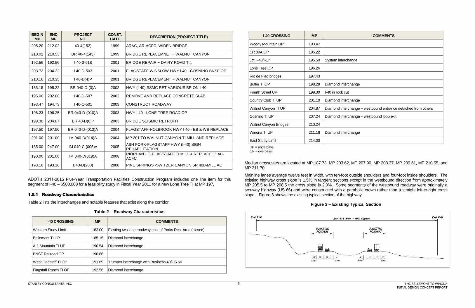
ADOT’s 2011-2015 Five-Year Transportation Facilities Construction Program includes one line item for this segment of I-40 – $500,000 for a feasibility study in Fiscal Year 2011 for a new Lone Tree TI at MP 197.
1.5.1 Roadway Characteristics
Table 2 lists the interchanges and notable features that exist along the corridor.
Table 2 – Roadway Characteristics
I-40 CROSSING MP COMMENTS
Western Study Limit 183.00 Existing two lane roadway east of Parks Rest Area (closed)
Bellemont TI UP 185.15 Diamond interchange
A-1 Mountain TI UP 190.54 Diamond interchange
BNSF Railroad OP 190.86
West Flagstaff TI OP 191.69 Trumpet interchange with Business 40/US 66
Flagstaff Ranch TI OP 192.56 Diamond interchange
I-40 CROSSING MP COMMENTS
Woody Mountain UP 193.47
SR 89A OP 195.22
Jct. I-40/I-17 195.50 System interchange
Lone Tree OP 196.26
Rio de Flag bridges 197.43
Butler TI OP 198.28 Diamond interchange
Fourth Street UP 199.30 I-40 in rock cut
Country Club TI UP 201.10 Diamond interchange
Walnut Canyon TI UP 204.87 Diamond interchange – westbound entrance detached from others
Cosnino TI UP 207.24 Diamond interchange – westbound loop exit
Walnut Canyon Bridges 210.24
Winona TI UP 211.16 Diamond interchange
East Study Limit 214.00
UP = underpass OP = overpass
Median crossovers are located at MP 187.73, MP 203.62, MP 207.90, MP 208.37, MP 209.61, MP 210.55, and MP 211.70.
Mainline lanes average twelve feet in width, with ten-foot outside shoulders and four-foot inside shoulders. The existing highway cross slope is 1.5% in tangent sections except in the westbound direction from approximately MP 205.5 to MP 208.5 the cross slope is 2.0%. Some segments of the westbound roadway were originally a two-way highway (US 66) and were constructed with a parabolic crown rather than a straight left-to-right cross slope. Figure 3 shows the existing typical section of the highway.
Figure 3 – Existing Typical Section
STANLEY CONSULTANTS, INC. 6 I-40, BELLEMONT TO WINONA
INITIAL DESIGN CONCEPT REPORT
The American Association of State Highway and Transportation Officials (AASHTO) publishes guidelines for a range of geometric design criteria including the horizontal degree of curvature, superelevation rate, and profile grade in A Policy on Geometric Design of Highways and Streets. The AASHTO Controlling Design Criteria Report documents characteristics of the existing alignment and notes which criteria exceed limits set forth by the guidelines. Appendix A contains a summary of the mainline horizontal and vertical design data.
The corridor can be separated into three segments based on terrain or functional classification:
MP 183.0-193.0 – Rural - Rolling Terrain
MP 193.0-203.0 − Urban/Fringe Urban
MP 203.0-214.0 – Rural - Rolling Terrain
Rural/Rolling Terrain Segment (MP 183.0 to MP 193.0)
The western limits of the study area are in rolling terrain, which extends from east of the Parks rest area (MP 181.74) through the Bellemont Flat in the KNF and CNF. The National Forest boundary is at MP 186.05 The Arizona Divide at MP 190.0 marks the location where the watershed of the Little Colorado River breaks away from Verde River. This is the highest point on I-40, and after a 1941 realignment, was the highest point on Old US 66 at 7335 feet. The existing grades range from -4.0% to +3.97% in the eastbound direction and from +4.0% to -4.75% in the westbound direction.
The eastbound and westbound roadways follow independent horizontal alignments through this segment. The existing eastbound and westbound I-40 horizontal alignments consist of curves with degrees of curvature ranging from 0º 20' to 2º 15' 09”. The alignments generally follow the natural rolling terrain. Median widths vary from 84 feet to more than 400 feet.
The Bellemont TI is located at MP 185.15 and is a diamond interchange with Transwestern Road. Transwestern Road provides access to residential communities north of I-40. The former 1942 US Navajo Ordnance Depot, now owned by the Arizona National Guard and known as Camp Navajo, is located south of I-40 from west of the Bellemont TI to east of MP 188.
The terrain from MP 189.0 to MP 190.8 is more severe than elsewhere within the project limits. Rock cuts exceed 80 feet in height in some areas with slopes of 1H:1V.
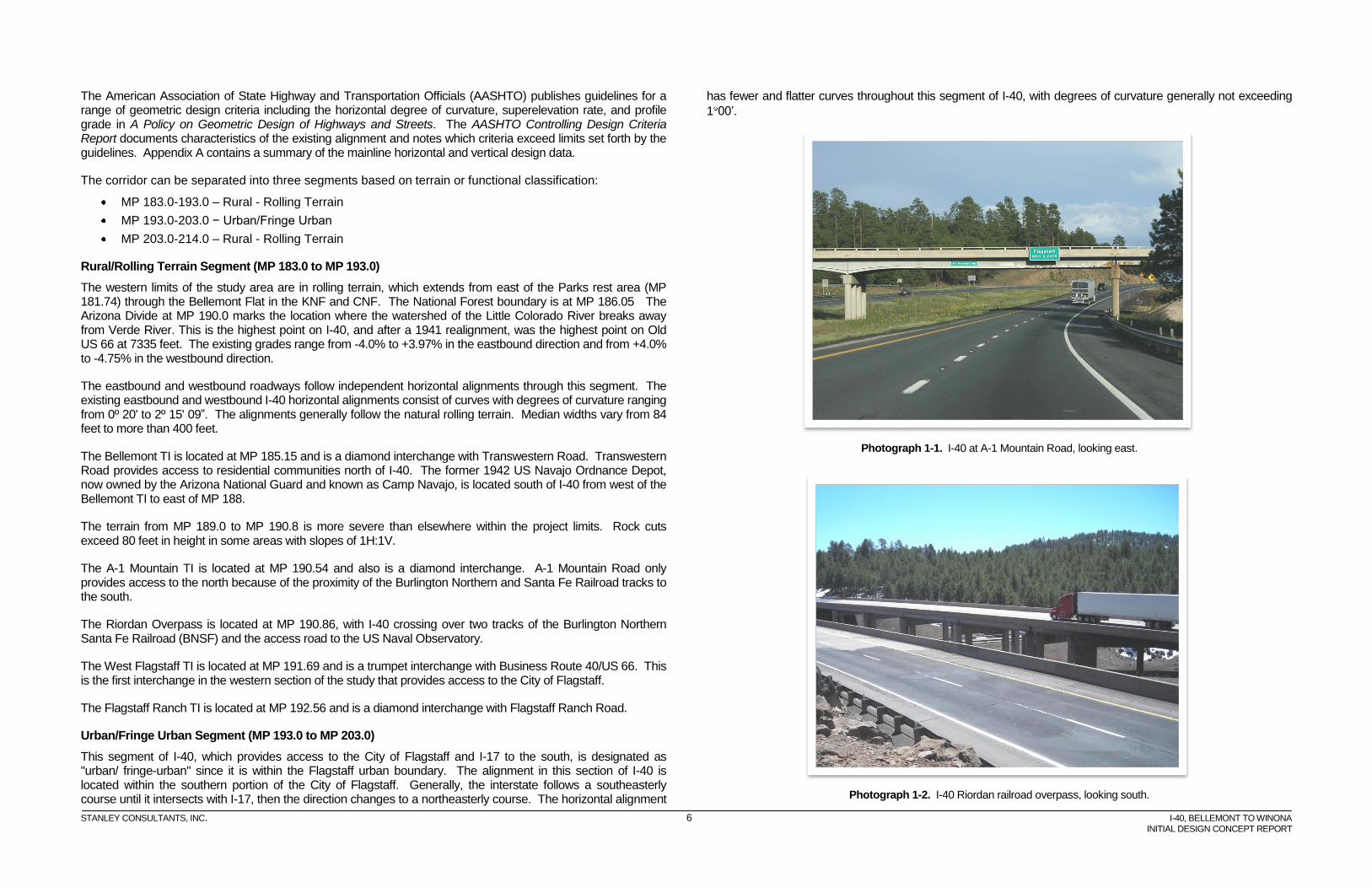
The A-1 Mountain TI is located at MP 190.54 and also is a diamond interchange. A-1 Mountain Road only provides access to the north because of the proximity of the Burlington Northern and Santa Fe Railroad tracks to the south.
The Riordan Overpass is located at MP 190.86, with I-40 crossing over two tracks of the Burlington Northern Santa Fe Railroad (BNSF) and the access road to the US Naval Observatory.
The West Flagstaff TI is located at MP 191.69 and is a trumpet interchange with Business Route 40/US 66. This is the first interchange in the western section of the study that provides access to the City of Flagstaff.
The Flagstaff Ranch TI is located at MP 192.56 and is a diamond interchange with Flagstaff Ranch Road.
Urban/Fringe Urban Segment (MP 193.0 to MP 203.0)
This segment of I-40, which provides access to the City of Flagstaff and I-17 to the south, is designated as "urban/ fringe-urban" since it is within the Flagstaff urban boundary. The alignment in this section of I-40 is located within the southern portion of the City of Flagstaff. Generally, the interstate follows a southeasterly course until it intersects with I-17, then the direction changes to a northeasterly course. The horizontal alignment
has fewer and flatter curves throughout this segment of I-40, with degrees of curvature generally not exceeding
1 00’.
Photograph 1-1. I-40 at A-1 Mountain Road, looking east.
Photograph 1-2. I-40 Riordan railroad overpass, looking south.
STANLEY CONSULTANTS, INC. 7 I-40, BELLEMONT TO WINONA
INITIAL DESIGN CONCEPT REPORT
This ten-mile segment of I-40 has an overall elevation change of only 360 feet (7115 feet to 6755 feet); however, there is a steep section within a mile west of the system interchange with I-17. In this section, the existing grade in the eastbound direction is -5.0% and in the westbound direction +4.6%. The existing grades within this segment range from -5.0% to +2.0% in the eastbound direction and from -2.5% to +4.6% in the westbound direction.
There are one system interchange and two diamond interchanges in this segment.
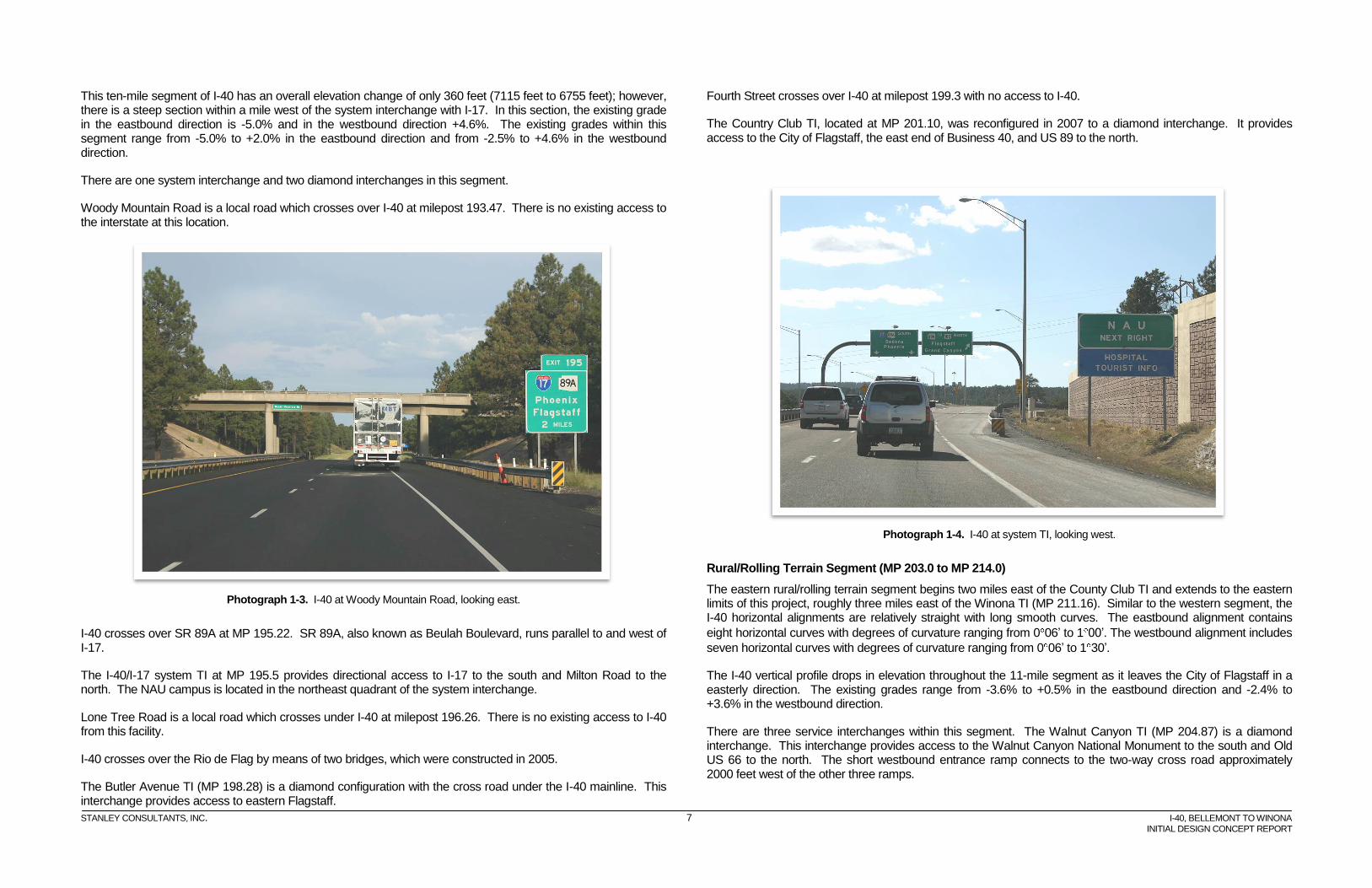
Woody Mountain Road is a local road which crosses over I-40 at milepost 193.47. There is no existing access to the interstate at this location.
Photograph 1-3. I-40 at Woody Mountain Road, looking east.
I-40 crosses over SR 89A at MP 195.22. SR 89A, also known as Beulah Boulevard, runs parallel to and west of I-17.
The I-40/I-17 system TI at MP 195.5 provides directional access to I-17 to the south and Milton Road to the north. The NAU campus is located in the northeast quadrant of the system interchange.
Lone Tree Road is a local road which crosses under I-40 at milepost 196.26. There is no existing access to I-40 from this facility.
I-40 crosses over the Rio de Flag by means of two bridges, which were constructed in 2005.
The Butler Avenue TI (MP 198.28) is a diamond configuration with the cross road under the I-40 mainline. This interchange provides access to eastern Flagstaff.
Fourth Street crosses over I-40 at milepost 199.3 with no access to I-40.
The Country Club TI, located at MP 201.10, was reconfigured in 2007 to a diamond interchange. It provides access to the City of Flagstaff, the east end of Business 40, and US 89 to the north.
Photograph 1-4. I-40 at system TI, looking west.
Rural/Rolling Terrain Segment (MP 203.0 to MP 214.0)
The eastern rural/rolling terrain segment begins two miles east of the County Club TI and extends to the eastern limits of this project, roughly three miles east of the Winona TI (MP 211.16). Similar to the western segment, the I-40 horizontal alignments are relatively straight with long smooth curves. The eastbound alignment contains
eight horizontal curves with degrees of curvature ranging from 0 06’ to 1 00’. The westbound alignment includes
seven horizontal curves with degrees of curvature ranging from 0 06’ to 1 30’.
The I-40 vertical profile drops in elevation throughout the 11-mile segment as it leaves the City of Flagstaff in a easterly direction. The existing grades range from -3.6% to +0.5% in the eastbound direction and -2.4% to +3.6% in the westbound direction.
There are three service interchanges within this segment. The Walnut Canyon TI (MP 204.87) is a diamond interchange. This interchange provides access to the Walnut Canyon National Monument to the south and Old US 66 to the north. The short westbound entrance ramp connects to the two-way cross road approximately 2000 feet west of the other three ramps.
STANLEY CONSULTANTS, INC. 8 I-40, BELLEMONT TO WINONA
INITIAL DESIGN CONCEPT REPORT
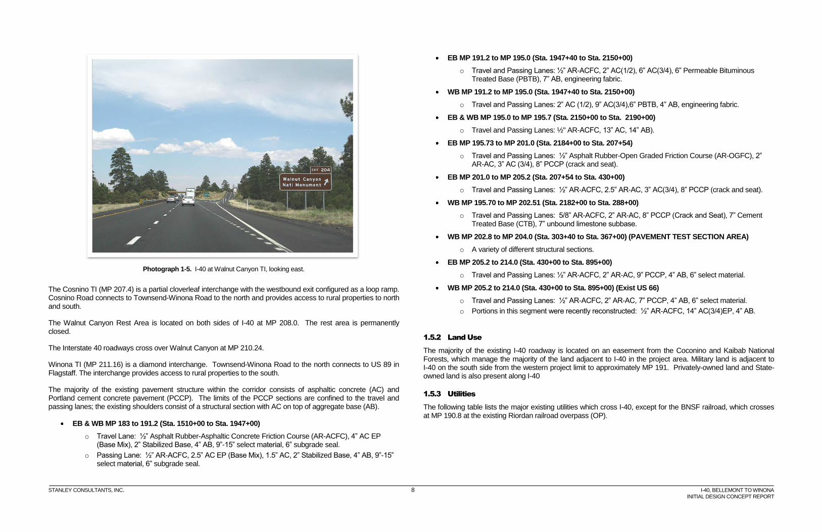
Photograph 1-5. I-40 at Walnut Canyon TI, looking east.
The Cosnino TI (MP 207.4) is a partial cloverleaf interchange with the westbound exit configured as a loop ramp. Cosnino Road connects to Townsend-Winona Road to the north and provides access to rural properties to north and south.
The Walnut Canyon Rest Area is located on both sides of I-40 at MP 208.0. The rest area is permanently closed.
The Interstate 40 roadways cross over Walnut Canyon at MP 210.24.
Winona TI (MP 211.16) is a diamond interchange. Townsend-Winona Road to the north connects to US 89 in Flagstaff. The interchange provides access to rural properties to the south.
The majority of the existing pavement structure within the corridor consists of asphaltic concrete (AC) and Portland cement concrete pavement (PCCP). The limits of the PCCP sections are confined to the travel and passing lanes; the existing shoulders consist of a structural section with AC on top of aggregate base (AB).
EB & WB MP 183 to 191.2 (Sta. 1510+00 to Sta. 1947+00)
o Travel Lane: ½” Asphalt Rubber-Asphaltic Concrete Friction Course (AR-ACFC), 4” AC EP (Base Mix), 2” Stabilized Base, 4” AB, 9”-15” select material, 6” subgrade seal.
o Passing Lane: ½” AR-ACFC, 2.5” AC EP (Base Mix), 1.5” AC, 2” Stabilized Base, 4” AB, 9”-15” select material, 6” subgrade seal.
EB MP 191.2 to MP 195.0 (Sta. 1947+40 to Sta. 2150+00)
o Travel and Passing Lanes: ½” AR-ACFC, 2” AC(1/2), 6” AC(3/4), 6” Permeable Bituminous Treated Base (PBTB), 7” AB, engineering fabric.
WB MP 191.2 to MP 195.0 (Sta. 1947+40 to Sta. 2150+00)
o Travel and Passing Lanes: 2” AC (1/2), 9” AC(3/4),6” PBTB, 4” AB, engineering fabric.
EB & WB MP 195.0 to MP 195.7 (Sta. 2150+00 to Sta. 2190+00)
o Travel and Passing Lanes: ½" AR-ACFC, 13” AC, 14” AB).
EB MP 195.73 to MP 201.0 (Sta. 2184+00 to Sta. 207+54)
o Travel and Passing Lanes: ½” Asphalt Rubber-Open Graded Friction Course (AR-OGFC), 2” AR-AC, 3” AC (3/4), 8” PCCP (crack and seat).
EB MP 201.0 to MP 205.2 (Sta. 207+54 to Sta. 430+00)
o Travel and Passing Lanes: ½” AR-ACFC, 2.5” AR-AC, 3” AC(3/4), 8” PCCP (crack and seat).
WB MP 195.70 to MP 202.51 (Sta. 2182+00 to Sta. 288+00)
o Travel and Passing Lanes: 5/8” AR-ACFC, 2” AR-AC, 8” PCCP (Crack and Seat), 7” Cement Treated Base (CTB), 7” unbound limestone subbase.
WB MP 202.8 to MP 204.0 (Sta. 303+40 to Sta. 367+00) (PAVEMENT TEST SECTION AREA)
o A variety of different structural sections.
EB MP 205.2 to 214.0 (Sta. 430+00 to Sta. 895+00)
o Travel and Passing Lanes: ½” AR-ACFC, 2” AR-AC, 9” PCCP, 4” AB, 6” select material.
WB MP 205.2 to 214.0 (Sta. 430+00 to Sta. 895+00) (Exist US 66)
o Travel and Passing Lanes: ½” AR-ACFC, 2” AR-AC, 7” PCCP, 4” AB, 6” select material.
o Portions in this segment were recently reconstructed: ½” AR-ACFC, 14” AC(3/4)EP, 4” AB.
1.5.2 Land Use
The majority of the existing I-40 roadway is located on an easement from the Coconino and Kaibab National Forests, which manage the majority of the land adjacent to I-40 in the project area. Military land is adjacent to I-40 on the south side from the western project limit to approximately MP 191. Privately-owned land and State-owned land is also present along I-40
1.5.3 Utilities
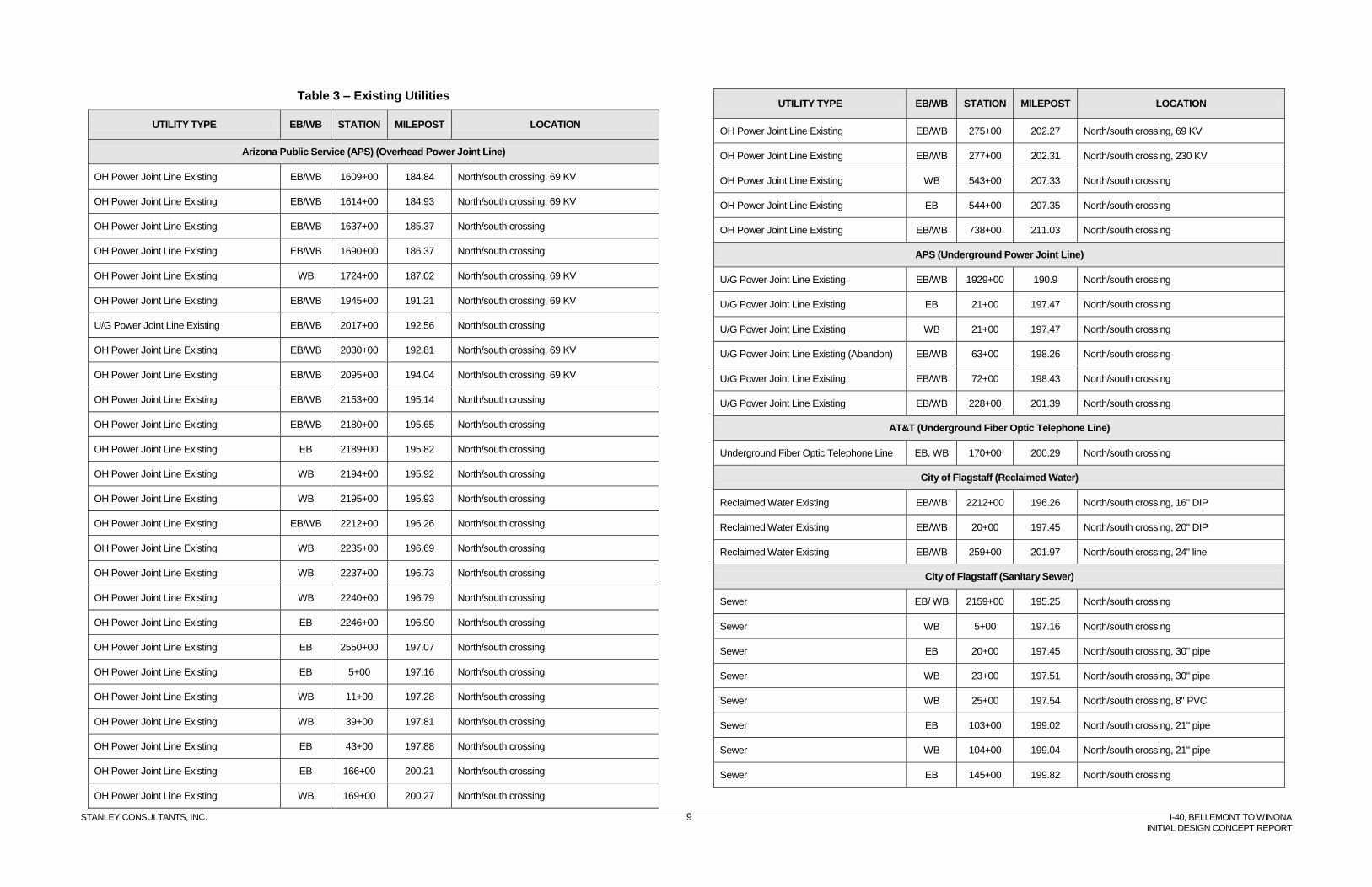
The following table lists the major existing utilities which cross I-40, except for the BNSF railroad, which crosses at MP 190.8 at the existing Riordan railroad overpass (OP).
STANLEY CONSULTANTS, INC. 9 I-40, BELLEMONT TO WINONA
INITIAL DESIGN CONCEPT REPORT
Table 3 – Existing Utilities
UTILITY TYPE EB/WB STATION MILEPOST LOCATION
Arizona Public Service (APS) (Overhead Power Joint Line)
OH Power Joint Line Existing EB/WB 1609+00 184.84 North/south crossing, 69 KV
OH Power Joint Line Existing EB/WB 1614+00 184.93 North/south crossing, 69 KV
OH Power Joint Line Existing EB/WB 1637+00 185.37 North/south crossing
OH Power Joint Line Existing EB/WB 1690+00 186.37 North/south crossing
OH Power Joint Line Existing WB 1724+00 187.02 North/south crossing, 69 KV
OH Power Joint Line Existing EB/WB 1945+00 191.21 North/south crossing, 69 KV
U/G Power Joint Line Existing EB/WB 2017+00 192.56 North/south crossing
OH Power Joint Line Existing EB/WB 2030+00 192.81 North/south crossing, 69 KV
OH Power Joint Line Existing EB/WB 2095+00 194.04 North/south crossing, 69 KV
OH Power Joint Line Existing EB/WB 2153+00 195.14 North/south crossing
OH Power Joint Line Existing EB/WB 2180+00 195.65 North/south crossing
OH Power Joint Line Existing EB 2189+00 195.82 North/south crossing
OH Power Joint Line Existing WB 2194+00 195.92 North/south crossing
OH Power Joint Line Existing WB 2195+00 195.93 North/south crossing
OH Power Joint Line Existing EB/WB 2212+00 196.26 North/south crossing
OH Power Joint Line Existing WB 2235+00 196.69 North/south crossing
OH Power Joint Line Existing WB 2237+00 196.73 North/south crossing
OH Power Joint Line Existing WB 2240+00 196.79 North/south crossing
OH Power Joint Line Existing EB 2246+00 196.90 North/south crossing
OH Power Joint Line Existing EB 2550+00 197.07 North/south crossing
OH Power Joint Line Existing EB 5+00 197.16 North/south crossing
OH Power Joint Line Existing WB 11+00 197.28 North/south crossing
OH Power Joint Line Existing WB 39+00 197.81 North/south crossing
OH Power Joint Line Existing EB 43+00 197.88 North/south crossing
OH Power Joint Line Existing EB 166+00 200.21 North/south crossing
OH Power Joint Line Existing WB 169+00 200.27 North/south crossing
UTILITY TYPE EB/WB STATION MILEPOST LOCATION
OH Power Joint Line Existing EB/WB 275+00 202.27 North/south crossing, 69 KV
OH Power Joint Line Existing EB/WB 277+00 202.31 North/south crossing, 230 KV
OH Power Joint Line Existing WB 543+00 207.33 North/south crossing
OH Power Joint Line Existing EB 544+00 207.35 North/south crossing
OH Power Joint Line Existing EB/WB 738+00 211.03 North/south crossing
APS (Underground Power Joint Line)
U/G Power Joint Line Existing EB/WB 1929+00 190.9 North/south crossing
U/G Power Joint Line Existing EB 21+00 197.47 North/south crossing
U/G Power Joint Line Existing WB 21+00 197.47 North/south crossing
U/G Power Joint Line Existing (Abandon) EB/WB 63+00 198.26 North/south crossing
U/G Power Joint Line Existing EB/WB 72+00 198.43 North/south crossing
U/G Power Joint Line Existing EB/WB 228+00 201.39 North/south crossing
AT&T (Underground Fiber Optic Telephone Line)
Underground Fiber Optic Telephone Line EB, WB 170+00 200.29 North/south crossing
City of Flagstaff (Reclaimed Water)
Reclaimed Water Existing EB/WB 2212+00 196.26 North/south crossing, 16" DIP
Reclaimed Water Existing EB/WB 20+00 197.45 North/south crossing, 20" DIP
Reclaimed Water Existing EB/WB 259+00 201.97 North/south crossing, 24" line
City of Flagstaff (Sanitary Sewer)
Sewer EB/ WB 2159+00 195.25 North/south crossing
Sewer WB 5+00 197.16 North/south crossing
Sewer EB 20+00 197.45 North/south crossing, 30" pipe
Sewer WB 23+00 197.51 North/south crossing, 30" pipe
Sewer WB 25+00 197.54 North/south crossing, 8" PVC
Sewer EB 103+00 199.02 North/south crossing, 21" pipe
Sewer WB 104+00 199.04 North/south crossing, 21" pipe
Sewer EB 145+00 199.82 North/south crossing
STANLEY CONSULTANTS, INC. 10 I-40, BELLEMONT TO WINONA
INITIAL DESIGN CONCEPT REPORT
UTILITY TYPE EB/WB STATION MILEPOST LOCATION
Sewer WB 147+00 199.85 North/south crossing
Sewer EB/WB 198+00 200.82 North/south crossing
Sewer EB/WB 259+00 201.97 North/south crossing, 33" Pipe
City of Flagstaff (Water Line)
Water Line Existing EB 2098+00 194.1 North/south crossing
Water Line Existing WB 2100+00 194.14 North/south crossing
Water Line Existing EB/WB 2160+00 195.27 North/south crossing
Water Line Existing EB/WB 2212+00 196.26 North/south crossing
Water Line Existing EB 20+00 197.45 North/south crossing, 20" steel
Water Line Existing WB 23+00 197.51 North/south crossing, 30" DIP
Water Line (Abandon) EB/WB 63+00 198.26 North/south crossing, 24" DIP
Water Line Existing WB 165+00 200.19 North/south crossing, 12 pipe
Water Line Existing EB 167+00 200.23 North/south crossing, 12" pipe
Water Line Existing EB 221+00 201.25 North/south crossing, 12" pipe
Water Line Existing WB 226+00 201.35 North/south crossing, 12" pipe
NPG Cable
Underground Cable Television Line EB/WB 2212+00 196.26 North/south crossing
Qwest
OH Telephone Line Existing EB/WB 1609+00 184.84 North/south crossing
OH Telephone Line Existing EB/WB 1637+00 185.37 North/south crossing
OH Telephone Line Existing EB/WB 1673+00 186.05 North/south crossing
OH Telephone Line Existing EB/WB 1939+00 191.09 North/south crossing
OH Telephone Line Existing WB 39+00 197.81 North/south crossing
OH Telephone Line Existing EB 43+00 197.88 North/south crossing
OH Telephone Line Existing EB 494+00 206.41 North/south crossing
OH Telephone Line Existing WB 495+00 206.42 North/south crossing
OH Telephone Line Existing EB/WB 738+00 211.03 North/south crossing
UTILITY TYPE EB/WB STATION MILEPOST LOCATION
UNISOURCE Gas
Gas line Existing EB/WB 1640+00 185.43 North/south crossing, 2" pipe
Gas line Existing EB/WB 1663+00 185.86 North/south crossing, 2" pipe
Gas line Existing EB/WB 1672+00 186.03 North/south crossing, 6" pipe
Gas line Existing EB/WB 2017+00 192.56 North/south crossing, 8" pipe
Gas line Existing EB/WB 2212+00 196.26 North/south crossing, 2" pipe
Gas line Existing EB/WB 72+00 198.43 North/south crossing, 6" pipe
Gas line Existing EB/WB 169+00 200.27 North/south crossing, 4" pipe
Gas line Existing EB 221+00 201.25 North/south crossing, 6" pipe
Gas line Existing WB 227+00 201.37 North/south crossing, 6" pipe
WESTERN AREA POWER ADMINISTRATION
OH Power Joint Line Existing EB/WB 790+00 212.01 North/south crossing
OH Power Joint Line Existing EB/WB 791+00 212.03 North/south crossing
OH Power Joint Line Existing EB/WB 792+00 212.05 North/south crossing
OH Power Joint Line Existing EB/WB 793+00 212.07 North/south crossing
1.5.4 Drainage
Existing Drainage Conditions and Facilities
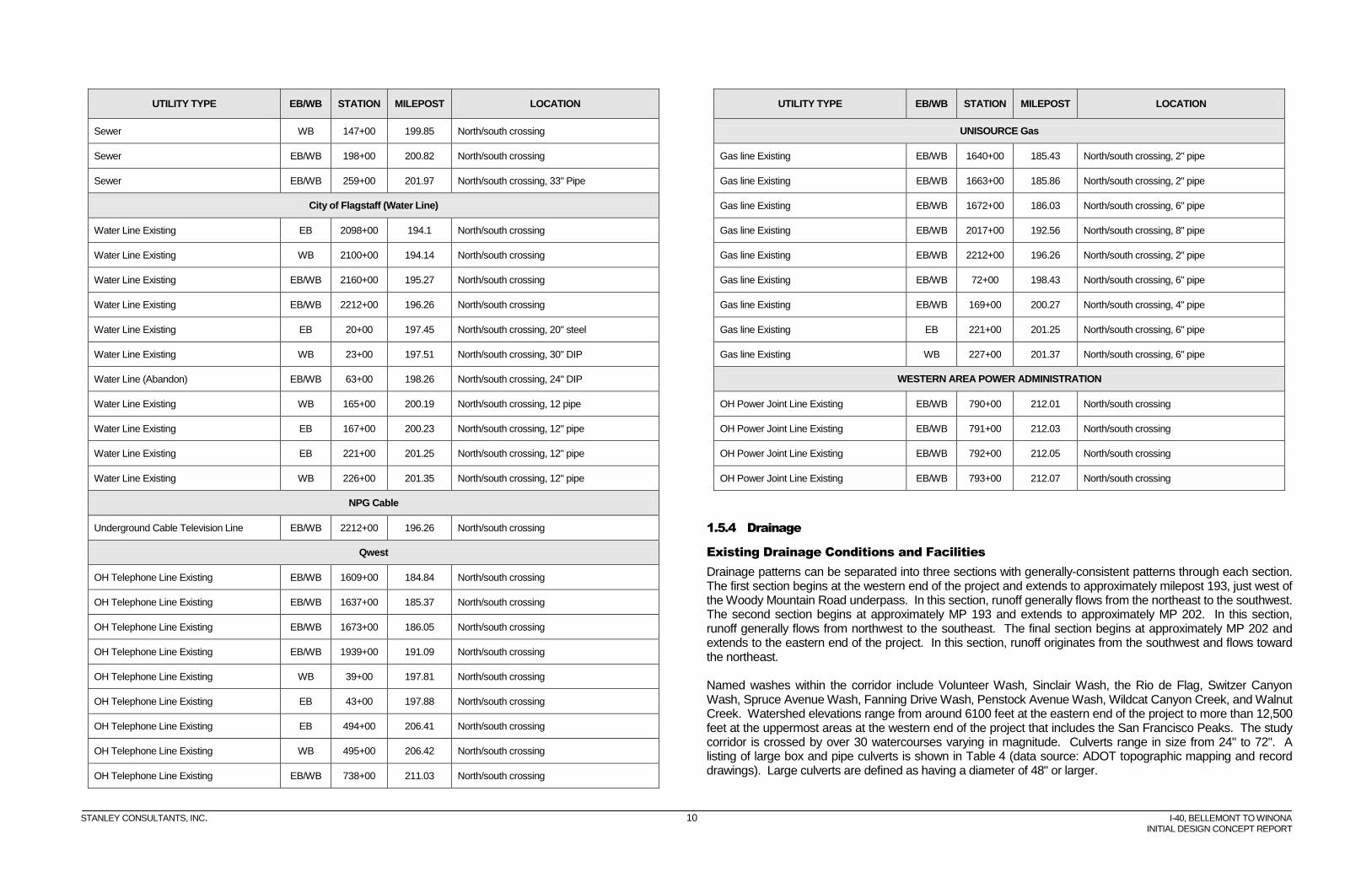
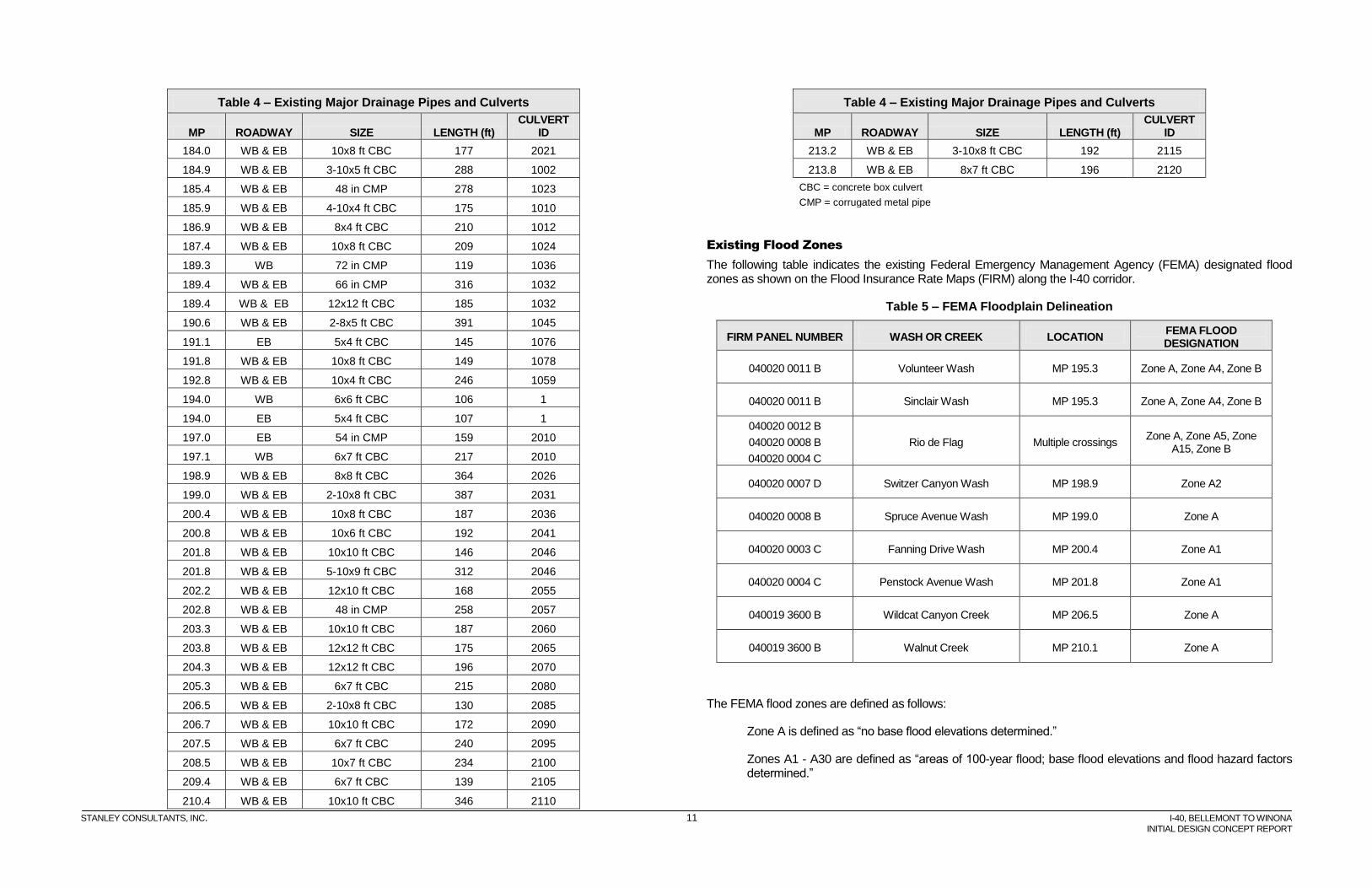
Drainage patterns can be separated into three sections with generally-consistent patterns through each section. The first section begins at the western end of the project and extends to approximately milepost 193, just west of the Woody Mountain Road underpass. In this section, runoff generally flows from the northeast to the southwest. The second section begins at approximately MP 193 and extends to approximately MP 202. In this section, runoff generally flows from northwest to the southeast. The final section begins at approximately MP 202 and extends to the eastern end of the project. In this section, runoff originates from the southwest and flows toward the northeast. Named washes within the corridor include Volunteer Wash, Sinclair Wash, the Rio de Flag, Switzer Canyon Wash, Spruce Avenue Wash, Fanning Drive Wash, Penstock Avenue Wash, Wildcat Canyon Creek, and Walnut Creek. Watershed elevations range from around 6100 feet at the eastern end of the project to more than 12,500 feet at the uppermost areas at the western end of the project that includes the San Francisco Peaks. The study corridor is crossed by over 30 watercourses varying in magnitude. Culverts range in size from 24" to 72". A listing of large box and pipe culverts is shown in Table 4 (data source: ADOT topographic mapping and record drawings). Large culverts are defined as having a diameter of 48" or larger.
STANLEY CONSULTANTS, INC. 11 I-40, BELLEMONT TO WINONA
INITIAL DESIGN CONCEPT REPORT
Table 4 – Existing Major Drainage Pipes and Culverts
MP ROADWAY SIZE LENGTH (ft) CULVERT
ID
184.0 WB & EB 10x8 ft CBC 177 2021
184.9 WB & EB 3-10x5 ft CBC 288 1002
185.4 WB & EB 48 in CMP 278 1023
185.9 WB & EB 4-10x4 ft CBC 175 1010
186.9 WB & EB 8x4 ft CBC 210 1012
187.4 WB & EB 10x8 ft CBC 209 1024
189.3 WB 72 in CMP 119 1036
189.4 WB & EB 66 in CMP 316 1032
189.4 WB & EB 12x12 ft CBC 185 1032
190.6 WB & EB 2-8x5 ft CBC 391 1045
191.1 EB 5x4 ft CBC 145 1076
191.8 WB & EB 10x8 ft CBC 149 1078
192.8 WB & EB 10x4 ft CBC 246 1059
194.0 WB 6x6 ft CBC 106 1
194.0 EB 5x4 ft CBC 107 1
197.0 EB 54 in CMP 159 2010
197.1 WB 6x7 ft CBC 217 2010
198.9 WB & EB 8x8 ft CBC 364 2026
199.0 WB & EB 2-10x8 ft CBC 387 2031
200.4 WB & EB 10x8 ft CBC 187 2036
200.8 WB & EB 10x6 ft CBC 192 2041
201.8 WB & EB 10x10 ft CBC 146 2046
201.8 WB & EB 5-10x9 ft CBC 312 2046
202.2 WB & EB 12x10 ft CBC 168 2055
202.8 WB & EB 48 in CMP 258 2057
203.3 WB & EB 10x10 ft CBC 187 2060
203.8 WB & EB 12x12 ft CBC 175 2065
204.3 WB & EB 12x12 ft CBC 196 2070
205.3 WB & EB 6x7 ft CBC 215 2080
206.5 WB & EB 2-10x8 ft CBC 130 2085
206.7 WB & EB 10x10 ft CBC 172 2090
207.5 WB & EB 6x7 ft CBC 240 2095
208.5 WB & EB 10x7 ft CBC 234 2100
209.4 WB & EB 6x7 ft CBC 139 2105
210.4 WB & EB 10x10 ft CBC 346 2110
Table 4 – Existing Major Drainage Pipes and Culverts
MP ROADWAY SIZE LENGTH (ft) CULVERT
ID
213.2 WB & EB 3-10x8 ft CBC 192 2115
213.8 WB & EB 8x7 ft CBC 196 2120
CBC = concrete box culvert
CMP = corrugated metal pipe
Existing Flood Zones
The following table indicates the existing Federal Emergency Management Agency (FEMA) designated flood zones as shown on the Flood Insurance Rate Maps (FIRM) along the I-40 corridor.
Table 5 – FEMA Floodplain Delineation
FIRM PANEL NUMBER WASH OR CREEK LOCATION FEMA FLOOD DESIGNATION
040020 0011 B Volunteer Wash MP 195.3 Zone A, Zone A4, Zone B
040020 0011 B Sinclair Wash MP 195.3 Zone A, Zone A4, Zone B
040020 0012 B
040020 0008 B
040020 0004 C
Rio de Flag Multiple crossings Zone A, Zone A5, Zone
A15, Zone B
040020 0007 D Switzer Canyon Wash MP 198.9 Zone A2
040020 0008 B Spruce Avenue Wash MP 199.0 Zone A
040020 0003 C Fanning Drive Wash MP 200.4 Zone A1
040020 0004 C Penstock Avenue Wash MP 201.8 Zone A1
040019 3600 B Wildcat Canyon Creek MP 206.5 Zone A
040019 3600 B Walnut Creek MP 210.1 Zone A
The FEMA flood zones are defined as follows:
Zone A is defined as “no base flood elevations determined.”
Zones A1 - A30 are defined as “areas of 100-year flood; base flood elevations and flood hazard factors determined.”
STANLEY CONSULTANTS, INC. 12 I-40, BELLEMONT TO WINONA
INITIAL DESIGN CONCEPT REPORT
Zone B is defined as “areas between limits of the 100-year flood and 500-year flood; or certain areas subject to 100-year flooding with average depths less than one (1) foot or where the contributing drainage area is less than one square mile; or areas protected by levees from the base flood. (medium shading)”
The remaining areas adjacent to I-40 are identified as Zone C. FEMA defines Zone C as “areas of minimal flooding. (no shading)”
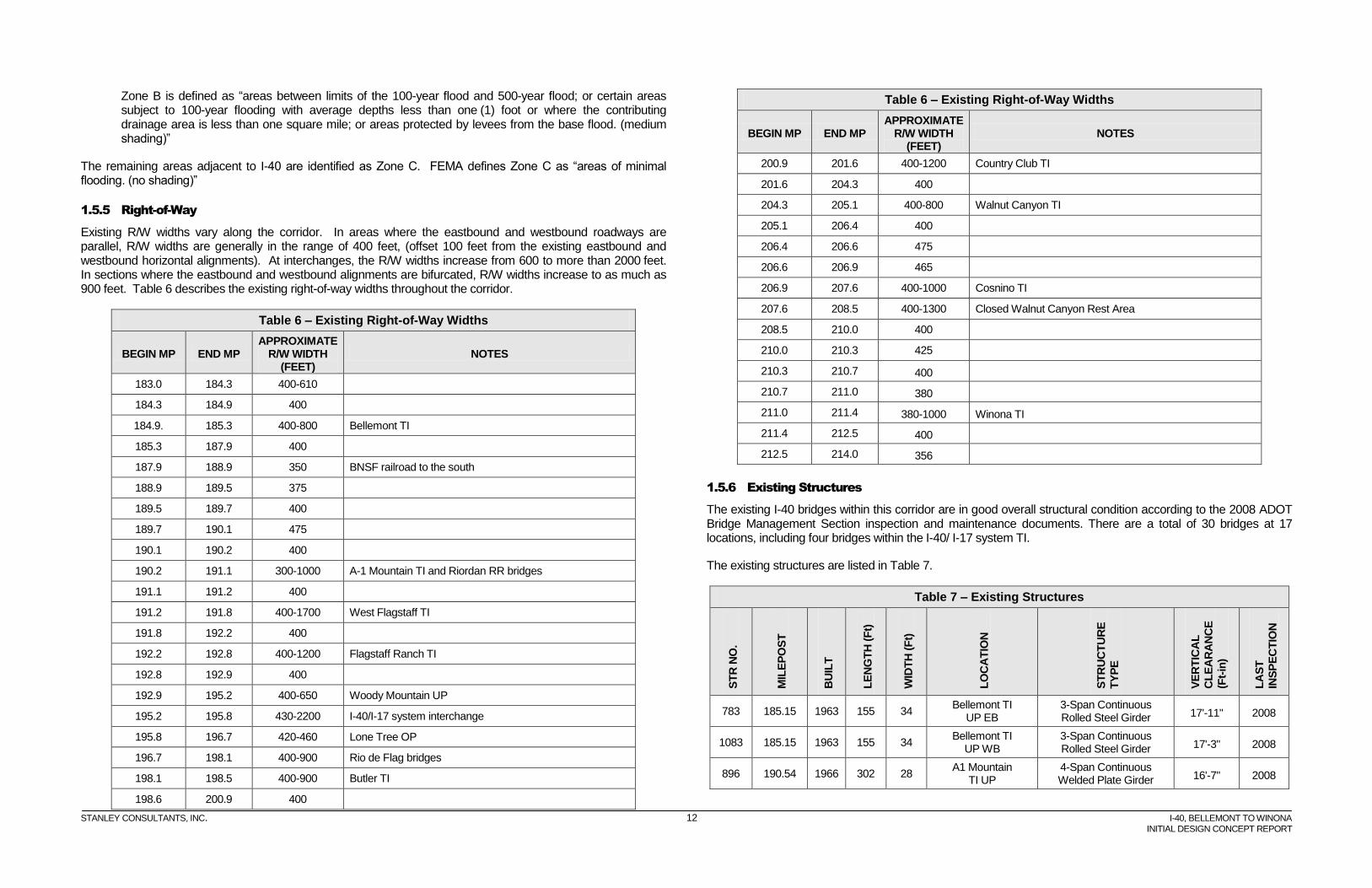
1.5.5 Right-of-Way
Existing R/W widths vary along the corridor. In areas where the eastbound and westbound roadways are parallel, R/W widths are generally in the range of 400 feet, (offset 100 feet from the existing eastbound and westbound horizontal alignments). At interchanges, the R/W widths increase from 600 to more than 2000 feet. In sections where the eastbound and westbound alignments are bifurcated, R/W widths increase to as much as 900 feet. Table 6 describes the existing right-of-way widths throughout the corridor.
Table 6 – Existing Right-of-Way Widths
BEGIN MP END MP APPROXIMATE
R/W WIDTH (FEET)
NOTES
183.0 184.3 400-610
184.3 184.9 400
184.9. 185.3 400-800 Bellemont TI
185.3 187.9 400
187.9 188.9 350 BNSF railroad to the south
188.9 189.5 375
189.5 189.7 400
189.7 190.1 475
190.1 190.2 400
190.2 191.1 300-1000 A-1 Mountain TI and Riordan RR bridges
191.1 191.2 400
191.2 191.8 400-1700 West Flagstaff TI
191.8 192.2 400
192.2 192.8 400-1200 Flagstaff Ranch TI
192.8 192.9 400
192.9 195.2 400-650 Woody Mountain UP
195.2 195.8 430-2200 I-40/I-17 system interchange
195.8 196.7 420-460 Lone Tree OP
196.7 198.1 400-900 Rio de Flag bridges
198.1 198.5 400-900 Butler TI
198.6 200.9 400
Table 6 – Existing Right-of-Way Widths
BEGIN MP END MP APPROXIMATE
R/W WIDTH (FEET)
NOTES
200.9 201.6 400-1200 Country Club TI
201.6 204.3 400
204.3 205.1 400-800 Walnut Canyon TI
205.1 206.4 400
206.4 206.6 475
206.6 206.9 465
206.9 207.6 400-1000 Cosnino TI
207.6 208.5 400-1300 Closed Walnut Canyon Rest Area
208.5 210.0 400
210.0 210.3 425
210.3 210.7 400
210.7 211.0 380
211.0 211.4 380-1000 Winona TI
211.4 212.5 400
212.5 214.0 356
1.5.6 Existing Structures
The existing I-40 bridges within this corridor are in good overall structural condition according to the 2008 ADOT Bridge Management Section inspection and maintenance documents. There are a total of 30 bridges at 17 locations, including four bridges within the I-40/ I-17 system TI.
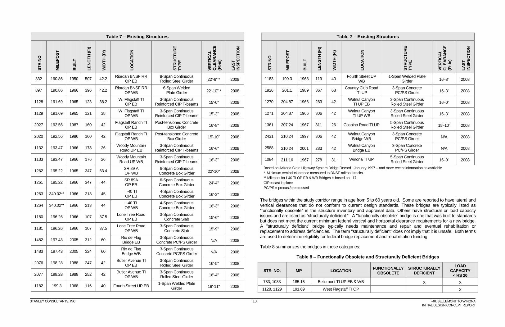
The existing structures are listed in Table 7.
Table 7 – Existing Structures
ST
R N
O.
MIL
EP
OS
T
BU
ILT
LE
NG
TH
(F
t)
WID
TH
(F
t)
LO
CA
TIO
N
ST
RU
CT
UR
E
TY
PE
VE
RT
ICA
L
CL
EA
RA
NC
E
(Ft-
in)
LA
ST
INS
PE
CT
ION
783 185.15 1963 155 34 Bellemont TI
UP EB 3-Span Continuous Rolled Steel Girder 17'-11" 2008
1083 185.15 1963 155 34 Bellemont TI
UP WB 3-Span Continuous Rolled Steel Girder 17'-3" 2008
896 190.54 1966 302 28 A1 Mountain
TI UP 4-Span Continuous Welded Plate Girder 16'-7" 2008
STANLEY CONSULTANTS, INC. 13 I-40, BELLEMONT TO WINONA
INITIAL DESIGN CONCEPT REPORT
Table 7 – Existing Structures S
TR
NO
.
MIL
EP
OS
T
BU
ILT
LE
NG
TH
(F
t)
WID
TH
(F
t)
LO
CA
TIO
N
ST
RU
CT
UR
E
TY
PE
VE
RT
ICA
L
CL
EA
RA
NC
E
(Ft-
in)
LA
ST
INS
PE
CT
ION
332 190.86 1950 507 42.2 Riordan BNSF RR
OP EB 8-Span Continuous Rolled Steel Girder 22'-6" * 2008
897 190.86 1966 396 42.2 Riordan BNSF RR
OP WB 6-Span Welded
Plate Girder 22'-10" * 2008
1128 191.69 1965 123 38.2 W. Flagstaff TI
OP EB 3-Span Continuous
Reinforced CIP T-beams 15'-0" 2008
1129 191.69 1965 121 38 W. Flagstaff TI
OP WB 3-Span Continuous
Reinforced CIP T-beams 15'-3" 2008
2027 192.56 1987 160 42 Flagstaff Ranch TI
OP EB Post-tensioned Concrete
Box Girder 16'-8" 2008
2020 192.56 1986 160 42 Flagstaff Ranch TI
OP WB Post-tensioned Concrete
Box Girder 15'-10" 2008
1132 193.47 1966 178 26 Woody Mountain
Road UP EB 3-Span Continuous
Reinforced CIP T-beams 16'-6" 2008
1133 193.47 1966 176 26 Woody Mountain
Road UP WB 3-Span Continuous
Reinforced CIP T-beams 16'-3" 2008
1262 195.22 1965 347 63.4 SR 89 A OP WB
6-Span Continuous Concrete Box Girder 22'-10" 2008
1261 195.22 1966 347 44 SR 89A OP EB
6-Span Continuous Concrete Box Girder 24'-4" 2008
1263 340.02** 1966 213 45 I-40 TI OP EB
4-Span Continuous Concrete Box Girder 16'-3" 2008
1264 340.02** 1966 213 44 I-40 TI OP WB
4-Span Continuous Concrete Box Girder 16'-3" 2008
1180 196.26 1966 107 37.5 Lone Tree Road
OP EB 3-Span Continuous
Concrete Slab 15'-6" 2008
1181 196.26 1966 107 37.5 Lone Tree Road
OP WB 3-Span Continuous
Concrete Slab 15'-9" 2008
1482 197.43 2005 312 60 Rio de Flag Bridge EB
3-Span Continuous Concrete PC/PS Girder N/A 2008
1483 197.43 2005 324 60 Rio de Flag Bridge WB
3-Span Continuous Concrete PC/PS Girder N/A 2008
2076 198.28 1988 247 42 Butler Avenue TI
OP EB 3-Span Continuous Rolled Steel Girder 16'-5" 2008
2077 198.28 1988 252 42 Butler Avenue TI
OP WB 3-Span Continuous Rolled Steel Girder 16'-4" 2008
1182 199.3 1968 116 40 Fourth Street UP EB 1-Span Welded Plate
Girder 19'-11" 2008
Table 7 – Existing Structures
ST
R N
O.
MIL
EP
OS
T
BU
ILT
LE
NG
TH
(F
t)
WID
TH
(F
t)
LO
CA
TIO
N
ST
RU
CT
UR
E
TY
PE
VE
RT
ICA
L
CL
EA
RA
NC
E
(Ft-
in)
LA
ST
INS
PE
CT
ION
1183 199.3 1968 119 40 Fourth Street UP
WB 1-Span Welded Plate
Girder 16'-8" 2008
1926 201.1 1989 367 68 Country Club Road
TI UP 3-Span Concrete
PC/PS Girder 16'-3" 2008
1270 204.87 1966 283 42 Walnut Canyon
TI UP EB 3-Span Continuous Rolled Steel Girder 16'-0" 2008
1271 204.87 1966 306 42 Walnut Canyon
TI UP WB 3-Span Continuous Rolled Steel Girder 16'-3" 2008
1361 207.24 1967 311 26 Cosnino Road TI UP 5-Span Continuous Rolled Steel Girder 15'-10" 2008
2431 210.24 1997 306 42 Walnut Canyon
Bridge WB 3-Span Concrete
PC/PS Girder N/A 2008
2588 210.24 2001 283 42 Walnut Canyon
Bridge EB 3-Span Concrete
PC/PS Girder N/A 2008
1084 211.16 1967 278 31 Winona TI UP 5-Span Continuous Rolled Steel Girder 16'-0" 2008
Based on Arizona State Highway System Bridge Record - January 1997 – and more recent information as available
* Minimum vertical clearance measured to BNSF railroad tracks.
** Milepost for I-40 TI OP EB & WB Bridges is based on I-17.
CIP = cast in place
PC/PS = precast/prestressed
The bridges within the study corridor range in age from 5 to 60 years old. Some are reported to have lateral and vertical clearances that do not conform to current design standards. These bridges are typically listed as “functionally obsolete” in the structure inventory and appraisal data. Others have structural or load capacity issues and are listed as “structurally deficient.” A "functionally obsolete" bridge is one that was built to standards but does not meet the current minimum federal vertical and horizontal clearance requirements for a new bridge. A "structurally deficient" bridge typically needs maintenance and repair and eventual rehabilitation or replacement to address deficiencies. The term "structurally deficient" does not imply that it is unsafe. Both terms are used to determine eligibility for federal bridge replacement and rehabilitation funding.
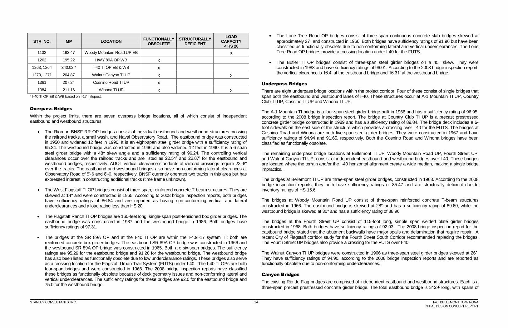
Table 8 summarizes the bridges in these categories:
Table 8 – Functionally Obsolete and Structurally Deficient Bridges
STR NO. MP LOCATION FUNCTIONALLY
OBSOLETE STRUCTURALLY
DEFICIENT
LOAD CAPACITY
< HS 20
783, 1083 185.15 Bellemont TI UP EB & WB X X
1128, 1129 191.69 West Flagstaff TI OP X
STANLEY CONSULTANTS, INC. 14 I-40, BELLEMONT TO WINONA
INITIAL DESIGN CONCEPT REPORT
STR NO. MP LOCATION FUNCTIONALLY
OBSOLETE STRUCTURALLY
DEFICIENT
LOAD CAPACITY
< HS 20
1132 193.47 Woody Mountain Road UP EB X
1262 195.22 HWY 89A OP WB X
1263, 1264 340.02 * I-40 TI OP EB & WB X
1270, 1271 204.87 Walnut Canyon TI UP X X
1361 207.24 Cosnino Road TI UP X
1084 211.16 Winona TI UP X X
* I-40 TI OP EB & WB based on I-17 milepost.
Overpass Bridges
Within the project limits, there are seven overpass bridge locations, all of which consist of independent eastbound and westbound structures.
The Riordan BNSF RR OP bridges consist of individual eastbound and westbound structures crossing the railroad tracks, a small wash, and Naval Observatory Road. The eastbound bridge was constructed in 1950 and widened 12 feet in 1990. It is an eight-span steel girder bridge with a sufficiency rating of 95.24. The westbound bridge was constructed in 1966 and also widened 12 feet in 1990. It is a 6-span
steel girder bridge with a 48 skew angle and a sufficiency rating of 96.24. The controlling vertical clearances occur over the railroad tracks and are listed as 22.51’ and 22.87’ for the eastbound and westbound bridges, respectively. ADOT vertical clearance standards at railroad crossings require 23’-6" over the tracks. The eastbound and westbound bridges also have non-conforming lateral clearances at Observatory Road of 5’-6 and 8’-0, respectively. BNSF currently operates two tracks in this area but has expressed interest in constructing additional tracks (time frame unknown).
The West Flagstaff TI OP bridges consist of three-span, reinforced concrete T-beam structures. They are
skewed at 14 and were constructed in 1965. According to 2008 bridge inspection reports, both bridges have sufficiency ratings of 86.84 and are reported as having non-conforming vertical and lateral underclearances and a load rating less than HS 20.
The Flagstaff Ranch TI OP bridges are 160-feet long, single-span post-tensioned box girder bridges. The eastbound bridge was constructed in 1987 and the westbound bridge in 1986. Both bridges have sufficiency ratings of 97.31.
The bridges at the SR 89A OP and at the I-40 TI OP are within the I-40/I-17 system TI; both are reinforced concrete box girder bridges. The eastbound SR 89A OP bridge was constructed in 1966 and the westbound SR 89A OP bridge was constructed in 1965. Both are six-span bridges. The sufficiency ratings are 95.29 for the eastbound bridge and 91.26 for the westbound bridge. The westbound bridge has also been listed as functionally obsolete due to low underclearance ratings. These bridges also serve as a crossing location for the Flagstaff Urban Trail System (FUTS) under I-40. The I-40 TI OPs are both four-span bridges and were constructed in 1966. The 2008 bridge inspection reports have classified these bridges as functionally obsolete because of deck geometry issues and non-conforming lateral and vertical underclearances. The sufficiency ratings for these bridges are 92.0 for the eastbound bridge and 75.0 for the westbound bridge.
The Lone Tree Road OP bridges consist of three-span continuous concrete slab bridges skewed at
approximately 27 and constructed in 1966. Both bridges have sufficiency ratings of 91.96 but have been classified as functionally obsolete due to non-conforming lateral and vertical underclearances. The Lone Tree Road OP bridges provide a crossing location under I-40 for the FUTS.
The Butler TI OP bridges consist of three-span steel girder bridges on a 45 skew. They were constructed in 1988 and have sufficiency ratings of 96.01. According to the 2008 bridge inspection report, the vertical clearance is 16.4’ at the eastbound bridge and 16.31’ at the westbound bridge.
Underpass Bridges
There are eight underpass bridge locations within the project corridor. Four of these consist of single bridges that span both the eastbound and westbound lanes of I-40. These structures occur at A-1 Mountain TI UP, Country Club TI UP, Cosnino TI UP and Winona TI UP.
The A-1 Mountain TI bridge is a four-span steel girder bridge built in 1966 and has a sufficiency rating of 96.95, according to the 2008 bridge inspection report. The bridge at Country Club TI UP is a precast prestressed concrete girder bridge constructed in 1989 and has a sufficiency rating of 89.84. The bridge deck includes a 6-foot sidewalk on the east side of the structure which provides a crossing over I-40 for the FUTS. The bridges at Cosnino Road and Winona are both five-span steel girder bridges. They were constructed in 1967 and have sufficiency ratings of 94.94 and 91.65, respectively. Both the Cosnino Road and Winona bridges have been classified as functionally obsolete.
The remaining underpass bridge locations at Bellemont TI UP, Woody Mountain Road UP, Fourth Street UP, and Walnut Canyon TI UP, consist of independent eastbound and westbound bridges over I-40. These bridges are located where the terrain and/or the I-40 horizontal alignment create a wide median, making a single bridge impractical.
The bridges at Bellemont TI UP are three-span steel girder bridges, constructed in 1963. According to the 2008 bridge inspection reports, they both have sufficiency ratings of 85.47 and are structurally deficient due to inventory ratings of HS-15.6.
The bridges at Woody Mountain Road UP consist of three-span reinforced concrete T-beam structures
constructed in 1966. The eastbound bridge is skewed at 28 and has a sufficiency rating of 89.60, while the
westbound bridge is skewed at 30 and has a sufficiency rating of 88.96.
The bridges at the Fourth Street UP consist of 115-foot long, simple span welded plate girder bridges constructed in 1968. Both bridges have sufficiency ratings of 92.93. The 2008 bridge inspection report for the eastbound bridge stated that the abutment backwalls have major spalls and delamination that require repair. A recent City of Flagstaff corridor study for the Fourth Street South Corridor recommended replacing the bridges. The Fourth Street UP bridges also provide a crossing for the FUTS over I-40.
The Walnut Canyon TI UP bridges were constructed in 1966 as three-span steel girder bridges skewed at 26 . They have sufficiency ratings of 94.90, according to the 2008 bridge inspection reports and are reported as functionally obsolete due to non-conforming underclearances.
Canyon Bridges
The existing Rio de Flag bridges are comprised of independent eastbound and westbound structures. Each is a
three-span precast prestressed concrete girder bridge. The total eastbound bridge is 312’ long, with spans of
STANLEY CONSULTANTS, INC. 15 I-40, BELLEMONT TO WINONA
INITIAL DESIGN CONCEPT REPORT
101.75’+103’+101.75’, and the westbound bridge overall length is 324’ , with span lengths of 105.75’+107’+105.75’. Both bridges were constructed in 2005 and have sufficiency ratings of 95.02.
The existing bridges cross the Rio de Flag, a tributary of the San Francisco Wash that eventually feeds into the Little Colorado River. Rain storms and snow melt drain to the Rio de Flag. Effluent from the Wildcat Hill Wastewater Treatment Plant is discharged into the channel, creating a small perennial stream. The Rio de Flag channel in this area is also part of the FUTS and crosses under I-40 at this location.
The existing Walnut Canyon bridges are also comprised of independent eastbound and westbound structures.
Each is a three-span precast prestressed concrete girder bridge. The eastbound bridge is 283’ long with spans
of 90’+95’+91’ and was constructed in 2001. The overall westbound bridge length is 306’ with span lengths of
99.5+101’+99’ and was constructed in 1997. Both bridges are skewed at 20 and have sufficiency ratings of 97.30.
Pipes and Box Culverts
Pipes and box culverts cross I-40 at numerous locations within the project corridor. Ten culverts appear on the ADOT Bridge Inventory with overall span lengths of 20 feet or more. The latest available inspection reports for these structures, dated 2006 and 2010, reflect sufficiency ratings ranging from 82.13 to 97.19.
1.5.7 Geotechnical
Geologic Setting
The project corridor is located in both the Colorado Plateau Physiographic Province which can be characterized as regionally elevated structural block consisting of gently dipping to flat lying, older sedimentary rocks that locally has been overlain by a thick sequence of volcanic rocks. Where exposed at the surface, the older sedimentary rocks have severely eroded to form a series of low hills and minor undulating valleys with entrenched, meandering drainage systems. Younger volcanic activity has subsequently modified large areas of this older terrain by burying the former valleys and drainages with thick sequences of volcanic lava flows and pyroclastic deposits.
The sedimentary rocks exposed in the general Flagstaff area consist of the Coconino Sandstone and the Kaibab Formation, both the Permian age, and the Moenkopi of Triassic age. The volcanic rocks of Tertiary to Quaternary age include basalt, andesite and dacite flows with agglomerate and cinder deposits from the San Francisco volcanic field. The bedrock sequence is locally overlain by alluvium, colluviums and residual soils formed by in situ rock decomposition, tuff deposits, cinder deposits, and manmade fill.
The San Francisco volcanic field, flanking the City of Flagstaff, is a large area of geologically recent, though currently dormant, volcanic activity that is responsible for creating most of the mountainous terrain features in the vicinity. Some of the most prominent examples of volcanic activity in the area are located just north of the I-40 corridor in the San Francisco Peaks. The majority of the volcanic features adjacent to the highway corridor are basaltic cinder cones. Major occurrences of volcanic deposits generally occur within the project corridor from MP 183.0 to MP 194.5, MP 197.8 to MP 199.05, and MP 210.5 to MP 212.0. Isolated smaller sections of volcanic materials are located throughout the study area.
The Kaibab Formation is divided into two distinct units. The lower unit is called the Fossil Mountain Member, and the upper unit is the Harrisburg Member. The Fossil Mountain Member is a light grey, cherty, thickly-bedded limestone to sandy limestone. The chert occurs in nodules, or lenses and layers of intra-formation breccias. The Harrisburg Member is an inter-bedded sequence of light red to gray limestone, dolomite, siltstone, sandstone, and gypsum. The Harrisburg Member of the Kaibab Formation is exposed from a quarter mile east of the I-40/ I-17 system interchange, at Lone Tree Road, Butler Avenue and the Fourth Street Bridge. From MP 201.95 to
MP 202.2, roughly a quarter mile east of the Rio de Flag, the Fossil Mountain Member is exposed in the highway road cuts. After this point the Harrisburg Member reemerges as the dominant exposure of Kaibab Formation except in the immediate area of the Walnut Canyon Bridge. The Harrisburg Member continues under the volcanic rocks at Winona east to MP 214, the eastern end of the study.
Soil Conditions
Within the project corridor, most of the bedrock is mantled by a veneer of colluviums. The colluviums generally are less than several feet in thickness, but may locally exceed ten feet. Colluvial deposits that overlie the Kaibab Formation typically range from medium to coarse grained silty sand with some coarse-grained gravel and occasional cobbles and small boulders. However, low to high plasticity clayey soil materials also occur due to the introduction of pyroclastic materials from past volcanic activity. Colluvial deposits that overlie basalt typically consist of well graded, subangular clayey sand and clay with varying amounts of cobbles and boulders. These deposits generally are medium to high in plasticity, dark brown to reddish brown and locally contain considerable organic material.
There are recent alluvial deposits in most of the larger drainages within the project corridor limits. The alluvial deposits typically are composed of sand and gravel with varying amounts of cobbles and boulders. The majority of these soils west of the Butler TI have a top cover of two to three inches of decomposing forest organics that are generally regarded as unusable construction material.
Existing Rockfall Hazards
ADOT’s Slope Management System (ASMS) has been in operation since 1989. The intent of the ASMS program was to be a proactive method for mitigating slopes with histories of rockfall hazards. The slope inventory process categorizes slopes along the state transportation system that have shown signs of rockfall events that are potentially hazardous and require recurrent maintenance activities. The inventory consists of field surveys which identified the sites and assigned a Severity Level with rankings from 1 through 5 with 5 as the most severe, and included comments concerning the types of problems encountered. The ADOT Materials Group reviews this information and compiles the data for further evaluation based on the Severity Level. For each indentified site, an additional field evaluation is conducted and integrated with information from the ADOT Districts' surveys into a systematic database which completes the inventory process. This database ranks the surveyed cut sections by priority points on a statewide basis. These rankings are used to aid in prioritizing future rockfall containment projects.
There are six identified rockfall sites within the project limits with notable priority point ratings.
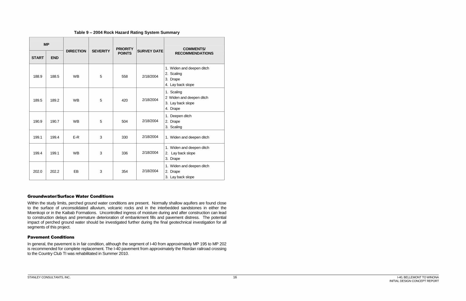
ADOT provided a 2004 Rock Hazard Rating System (RHRS) summary for existing cut slopes within the project limits. The summary lists: 1) the starting and ending mileposts of the cut, the direction of travel (E or W), and the side of the roadway (R or L) on which the cuts are located; 2) the severity (degree of instability) of the slope; 3) the number of priority points (the higher the number the greater the perceived instability of the slope); and 4) field comments and/or recommendations.
Three of the existing cut slopes in the project corridor were rated by ADOT as a 5 on the severity scale according to the 2004 RHRS. There are three other existing cut slopes rated 3 within the project limits. The cut slope inventory also identified a number of existing cut slopes with inadequate rockfall containment ditches.
In general, the existing cut slopes are generating a considerable amount of rockfall, small slides were observed in the cut slopes, and the rockfall containment ditches generally are undersized. Table 9 shows the existing cut slope rating from the 2004 RHRS.
STANLEY CONSULTANTS, INC. 16 I-40, BELLEMONT TO WINONA
INITIAL DESIGN CONCEPT REPORT
Table 9 – 2004 Rock Hazard Rating System Summary
MP
DIRECTION SEVERITY PRIORITY POINTS
SURVEY DATE COMMENTS/
RECOMMENDATIONS
START END
188.9 188.5 WB 5 558 2/18/2004
1. Widen and deepen ditch
2. Scaling
3. Drape
4. Lay back slope
189.5 189.2 WB 5 420 2/18/2004
1. Scaling
2 Widen and deepen ditch
3. Lay back slope
4. Drape
190.9 190.7 WB 5 504 2/18/2004
1. Deepen ditch
2. Drape
3. Scaling
199.1 199.4 E-R 3 330 2/18/2004 1. Widen and deepen ditch
199.4 199.1 WB 3 336 2/18/2004
1. Widen and deepen ditch
2. Lay back slope
3. Drape
202.0 202.2 EB 3 354 2/18/2004
1. Widen and deepen ditch
2. Drape
3. Lay back slope
Groundwater/Surface Water Conditions
Within the study limits, perched ground water conditions are present. Normally shallow aquifers are found close to the surface of unconsolidated alluvium, volcanic rocks and in the interbedded sandstones in either the Moenkopi or in the Kaibab Formations. Uncontrolled ingress of moisture during and after construction can lead to construction delays and premature deterioration of embankment fills and pavement distress. The potential impact of perched ground water should be investigated further during the final geotechnical investigation for all segments of this project.
Pavement Conditions
In general, the pavement is in fair condition, although the segment of I-40 from approximately MP 195 to MP 202 is recommended for complete replacement. The I-40 pavement from approximately the Riordan railroad crossing to the Country Club TI was rehabilitated in Summer 2010.