Embed Size (px)
Citation preview


Environmental Technology Verification
Test Report of Mobile Source Emissions Control Devices
Clean Diesel Technologies Fuel-Borne Catalyst with CleanAir System’s Diesel Oxidation Catalyst
Prepared by
Southwest Research Institute Research Triangle Institute
Under a Cooperative Agreement with U.S. Environmental Protection Agency

THE ENVIRONMENTAL TECHNOLOGY VERIFICATIONPROGRAM
U.S. Environmental Protection Agency
ETV Joint Verification Statement
TECHNOLOGY TYPE: MOBILE DIESEL ENGINE AIR POLLUTION CONTROL
APPLICATION: CONTROL OF EMISSIONS FROM MOBILE DIESEL ENGINES IN HIGHWAY USE BY DIESEL OXIDATION CATALYSTS
TECHNOLOGY NAME: CLEAN DIESEL TECHNOLOGIES, INC. FUEL-BORNE CATALYST WITH CLEANAIR SYSTEM’S DIESEL OXIDATION CATALYST
COMPANY: ADDRESS:
CLEAN DIESEL TECHNOLOGIES, INC. 300 ATLANTIC STREET STAMFORD, CT 06901-2522 PHONE: (203) 327-7050
The U.S. Environmental Protection Agency (EPA) has created the Environmental Technology Verification (ETV) Program to facilitate the deployment of innovative or improved environmental technologies through performance verification and dissemination of information. The goal of the ETV Program is to further environmental protection by accelerating the acceptance and use of improved and cost-effective technologies. ETV seeks to achieve this goal by providing high-quality, peer reviewed data on technology performance to those involved in the design, distribution, financing, permitting, purchase, and use of environmental technologies.
ETV works in partnership with recognized standards and testing organizations; stakeholder groups, which consist of buyers, vendor organizations, permitters, and other interested parties; and with the full participation of individual technology developers. The program evaluates the performance of innovative technologies by developing test plans that are responsive to the needs of stakeholders, conducting field or laboratory tests (as appropriate), collecting and analyzing data, and preparing peer-reviewed reports. All evaluations are conducted in accordance with rigorous quality assurance protocols to ensure that data of known and adequate quality are generated and that the results are defensible.
The Air Pollution Control Technology Verification Center (APCTVC), one of six centers under the ETV Program, is operated by Research Triangle Institute (RTI), in cooperation with EPA’s National Risk Management Research Laboratory. The APCTVC has evaluated the performance of an emissions control system consisting of a fuel-borne catalyst for mobile diesel engines used with a diesel oxidation catalyst muffler.
i

ETV TEST DESCRIPTION
All tests were performed in accordance with the Test/QA Plan for the Verification Testing of Diesel Exhaust Catalysts, PM Filters, and Engine Modification Technologies for Highway and Nonroad Use Diesel Engines and the Test-Specific Addendum to ETV Mobile Source Test/QA Plan for Clean Diesel Technologies, Inc. 0.5Pt/7.5Ce Catalyst & CleanAir DOC. These documents are written in accordance with the applicable generic verification protocol and include requirements for quality management, quality assurance, procedures for product selection, auditing of the test laboratories, and test reporting format.
The mobile diesel engine air pollution control technology was tested at Southwest Research Institute. The performance verified was the percentage emission reduction achieved by the technology for particulate matter (PM), nitrogen oxides (NOx), hydrocarbons (HC), and carbon monoxide (CO) relative to the performance of the same baseline engine without the technology in place. Operating cond itions were documented and ancillary performance measurements were also made. A summary description of the ETV test is provided in Table 1.
Table 1. Summary Description of the ETV Test
Test type Highway Transient Federal Test Procedure (FTP), heavy-duty cycle
Engine family LCE0505FAC5
Engine make–model year Cummins Engine Company–1990
Service class On-highway, heavy duty diesel engine
Engine rated power 206 kW (275 bhp) @ 2,000 rpm
Engine displacement 8.3 L
Technology Clean Diesel Technologies’ fuel-borne catalyst with CleanAir System’s Diesel Oxidation Catalyst
Technology description A platinum/cerium fuel-borne catalyst (0.5Pt/7.5Ce ppm) in ultralowsulfur diesel (ULSD) fuel combined with a diesel oxidation catalyst (Model CPD0950)
Test cycle or mode One cold-start and three hot-start tests according to FTP test description
Test fuel description EPA standard low-sulfur and ultralow-sulfur No. 2 diesel fuels per 40 CFR Part 86.1313
Critical measurements PM, NOx, HC, and CO
Ancillary measurements NO, NO2, CO2, exhaust back-pressure, exhaust temperature, and fuel consumption
ii

VERIFIED TECHNOLOGY DESCRIPTION
This verification statement is applicable to Clean Diesel Technologies’ platinum/cerium fuel-borne catalyst (FBC) at 0.5 ppm platinum and 7.5 ppm cerium (0.5Pt/7.5Ce ppm) ± 20% in commercial ULSD fuel (meeting the EPA specifications for 2007 at less than 15 ppm maximum sulfur content) with a lightly catalyzed diesel oxidation catalyst (DOC) manufactured by CleanAir Systems (Model CPD0950). It is applicable to engines fueled by ultralow-sulfur (15 ppm or less) diesel fuel.
This verification statement describes the performance of the tested technology on the diesel engine and fuels identified in Table 1.
VERIFICATION OF PERFORMANCE
The Clean Diesel Technologies fuel-borne catalyst used with CleanAir System’s Diesel Oxidation Catalyst achieved the reduction in tailpipe emissions shown in Table 2 compared to baseline operation with low-sulfur diesel (LSD) fuel.
Table 2. Verified Emissions Reductions for System Consisting of Clean Diesel Technologies fuel-borne catalyst with CleanAir Systems’s Diesel Oxidation Catalyst
Fuel Mean Emissions Reduction (%) 95% Confidence Limits on the
Emissions Reduction (%)
Device typea Baseline Controlled PM b
NOx HC CO PM b NOx HC CO
Degreened LSD FBC & ULSD
53 7.4 59 64 49-58 5.8-9.1 56-62 60-69
Aged LSD FBC & ULSD
48 2.8 37 54 44-53 1.7-3.9 30-45 50-58
a Degreened and Aged are defined in the generic verification protocol.b The verified PM emissions reduction combines reductions related to the control technology
and the change in fuel sulfur level.
For the purposes of determining the status of the technology in regard to EPA’s voluntary diesel retrofit program, the prospective user is encouraged to contact EPA’s Office of Transportation and Air Quality (OTAQ) or visit the retrofit program web site at http://www.epa.gov/otaq/retrofit/.
The APCTVC QA Officer has reviewed the test results and quality control data and has concluded that the data quality objectives given in the generic verification protocol and test/QA plan have been attained. EPA and APCTVC quality assurance staff have conducted technical assessments at the test laboratory and of the data handling. These confirm that the ETV tests were conducted in accordance with the EPA-approved test/QA plan.
This verification statement verifies the emissions characteristics of the Clean Diesel Technologies fuel-borne catalyst used with CleanAir System’s Diesel Oxidation Catalyst for the stated application. Extrapolation outside that range should be done with caution and an understanding of the scientific principles that control the performance of the technologies. This verification focused on emissions. Potential technology users may obtain other types of performance information from the manufacturer.
iii

In accordance with the generic verification protocol, this verification statement is valid, commencing on the date below, ind efinitely for application of Clean Diesel Technologies fuelborne catalyst used with CleanAir System’s diesel oxidation catalyst within the range of applicability of the statement.
Original signed by L. A. Mulkey 2/6/04 Original signed by A. R. Trenholm 2/5/04 Lee A. Mulkey Date Andrew R. Trenholm Date Acting Director Director National Risk Management Research Air Pollution Control Technology Laboratory Verification Center
Office of Research and Development United States Environmental Protection Agency
iv

Environmental Technology Verification Report
Mobile Source Retrofit Air Pollution Control Devices
Clean Diesel Technologies’ Fuel-borne Catalyst with CleanAir System’s Diesel Oxidation Catalyst
Prepared by
Research Triangle InstituteSouthwest Research Institute
EPA Cooperative Agreement No. CR829434-01-1
EPA Project Manager: Theodore G. Brna
Air Pollution and Control DivisionNational Risk Management Research Laboratory
Office of Research and DevelopmentU.S. Environmental Protection Agency
Research Triangle Park, NC 27711
February 2004

Notice
This document was prepared by Research Triangle Institute (RTI) and its subcontractor Southwest Research Institute (SwRI), with partial funding from Cooperative Agreement No. CR829434-01-1 with the U.S. Environmental Protection Agency (EPA). The document has been submitted to RTI/EPA’s peer and administrative reviews and has been approved for publication. Mention of corporation names, trade names, or commercial products does not constitute endorsement or recommendation for use of specific products.
vi

Foreword
The Environmental Technology Verification (ETV) Program, established by the U.S. Environmental Protection Agency (EPA), is designed to accelerate the development and commercialization of new or improved technologies through third-party verification and reporting of performance. The goal of the ETV Program is to verify the performance of commercially ready environmental technologies through the evaluation of objective and qualityassured data so that potential purchasers and permitters are provided with an independent and credible assessment of the technology that they are buying or permitting.
The Air Pollution Control Technology Verification Center is part of the EPA’s ETV Program and is operated as a partnership between Research Triangle Institute (RTI) and EPA. The Center verifies the performance of commercially ready air pollution control technologies. Verification tests use approved protocols and verified performance is reported in verification statements signed by EPA and RTI officials. RTI contracts with Southwest Research Institute (SwRI) to perform verification tests on engine emission control technologies.
Retrofit air pollution control devices used to control emissions from mobile diesel engines are among the technologies evaluated by the APCTVC. The APCTVC developed (and EPA approved) the Generic Verification Protocol for Diesel Exhaust Catalysts, Particulate Filters, and Engine Modification Control Technologies for Highway and Nonroad Use Diesel Engines to provide guidance on the verification testing of specific products that are designed to control emissions from diesel engines.
The following report reviews the performance of the Clean Diesel Technologies’ platinum/cerium fuel-borne catalyst used with CleanAir System’s Diesel Oxidation Catalyst (Model CPDo950). ETV testing of this technology was conducted during July 2003 at SwRI. All testing was performed in accordance with an approved test/QA plan that implements the requirements of the generic verification protocol at the test laboratory.
vii

Availability of Report
Copies of this verification report are available from
• Research Triangle Institute Engineering and Technology Division P.O. Box 12194Research Triangle Park, NC 27709-2194
• U.S. Environmental Protection Agency Air Pollution Prevention and Control Division (E343-02) 109 T. W. Alexander Drive Research Triangle Park, NC 27711
Web sites: http://www.epa.gov/etv/verifications/verification- index.html (electronic copy) http://www.epa.gov/ncepihom/
viii

Contents
ETV Joint Verification Statement.....................................................................................................i
Foreword ........................................................................................................................................vii
Availability of Report ...................................................................................................................viii
Figures..............................................................................................................................................x
Tables...............................................................................................................................................x
Acronyms/Abbreviations ................................................................................................................xi
Acknowledgments..........................................................................................................................xii
Section 1.0 Introduction....................................................................................................... 1
Section 2.0 Description of Products..................................................................................... 2
Section 3.0 Test Documentation.......................................................................................... 33.1 Engine Description................................................................................... 33.2 Engine Fuel Description........................................................................... 43.3 Summary of Emissions Measurement Procedures................................... 4
Emissions Test Procedures .......................................................................53.4 Deviations from the Test/QA Plan........................................................... 63.5 Documented Test Conditions................................................................... 7
Engine Performance ..................................................................................7Engine Exhaust Back-Pressure .................................................................7Engine Exhaust Temperature ....................................................................7Fuel Consumption.....................................................................................7
Section 4.0 Summary and Discussion of Emission Results................................................. 94.1 Quality Assurance .................................................................................. 13
Section 5.0 References ....................................................................................................... 14
ix

Figures
1. Aged DOC in Test Cell 4. .................................................................................................. 22. 1990 Cummins 8.3l heavy-duty diesel engine mounted in engine Test Cell 4.................. 43. Constant volume sampler setup for emissions measurement. ........................................... 6
Tables
1. Summary Description of the ETV Test ............................................................................. ii2. Selected Fuel Properties and Specifications ...................................................................... 53. Engine Performance Data .................................................................................................. 74. Brake Specific Fuel Consumption ..................................................................................... 85. Emissions Test Data......................................................................................................... 106. Composite Weighted Emissions Values (English units) ................................................. 117. Composite Weighted Emissions Values (metric units) ................................................... 128. Summary of Verification Test Emission Values ............................................................. 139. Summary of Verification Test Emission Reductions ....................................................... 13
x

Acronyms/Abbreviations
ºF degrees Fahrenheit NO2 nitrogen dioxide ºC degrees Celsius NOx nitrogen oxide APCTVC Air Pollution Control NDIR nondispersive infrared
Technology Verification OTAQ Office of Transportation and Center Air Quality
bhp brake horsepower Pa pascal(s) bhp-hr brake horsepower-hour PM particulate matter BSFC brake specific fuel ppm parts per million by volume
consumption QA quality assurance cm centimeter(s) QC quality control CFR Code of Federal Regulations rpm revolutions per minute CO carbon monoxide RTI Research Triangle Institute CO2 carbon dioxide SOP standard operating procedure DOC diesel oxidation catalyst SwRI Southwest Research Institute EPA US Environmental Protection TPM total particulate matter
Agency ULSD ultralow-sulfur diesel ETV Environmental Technology
Verification FTP Federal Test Procedure ft foot (feet) g gram(s) HC hydrocarbon(s) HD heavy duty HFID heated flame ionization
detector in. inch(es) in. Hg inch(es) mercury kW kilowatt(s) kWh kilowatt hour(s) kPa kilopascal(s) L liter(s) Lpm liters per minute lb pound(s) lb-ft pound foot (feet) LSD low-sulfur diesel m meter(s) min. minute(s) mm millimeter(s) N newton(s) N-m newton-meter NO nitrogen oxide
xi

Acknowledgments
The authors acknowledge the support of all of those who helped plan and conduct the verification activities. In particular, we would like to thank Theodore Brna, EPA’s Project Manager, and Paul Groff, EPA’s Quality Assurance Manager, both of EPA’s National Risk Management Research Laboratory in Research Triangle Park, NC. We would also like to acknowledge the assistance and participation of all the Clean Diesel Technologies, Inc. personnel who supported the test effort.
For more information on the Clean Diesel Technologies fuel-borne catalyst used with CleanAir System’s diesel oxidation catalyst, contact:
Mr. James Valentine Clean Diesel Technologies, Inc. 300 Atlantic Street Stamford, CT 06901-2522 Telephone: (203) 327-7050 Fax: (203) 323-0461 Email: [email protected] Web site: http://www.cdti.com/
For more information on verification testing of mobile sources air pollution control devices, contact
Ms. Jenni Elion Research Triangle Institute P.O. Box 12194 Research Triangle Park, NC 27709-2194 Telephone: (919) 541-6826 Email: [email protected] Web site: http://etv.rti.org/apct/index.html
xii

Section 1.0Introduction
This report reviews the performance of the Clean Diesel Technologies platinum/cerium fuelborne catalyst used with CleanAir System’s Diesel Oxidation Catalyst (Model CPD0950). Environmental Technology Verification (ETV) testing of this technology was conducted during a series of tests in July 2003 by Southwest Research Institute (SwRI) under contract with the Air Pollution Control Technology Verification Center (APCTVC). The objective of the APCTVC and the ETV Program is to verify, with high data quality, the performance of air pollution control technologies. Control of air emissions from diesel engines is within the scope of the APCTVC. An APCTVC program area was designed by Research Triangle Institute (RTI) and a technical panel of experts to evaluate the performance of diesel exhaust catalysts, particulate filters, and engine modification control technologies for mobile diesel engines. Based on the activities of this technical panel, the Generic Verification Protocol for Diesel Exhaust Catalysts, Particulate Filters, and Engine Modification Control Technologies for Highway and Nonroad Use Diesel Engines1 was developed. This protocol was chosen as the best guide to verify the immediate performance effects of Clean Diesel Technologies’ technology versus a protocol developed for fuel modifications. The verified technology incorporates both a catalyst added to the fuel and a device (the diesel oxidation catalyst). The specific test/quality assurance plan addendum for the ETV test of the technology submitted by Clean Diesel Technologies, Inc. was developed and approved on June 10, 2003.2 The goal of the test was to measure the emissions control performance of the technology system and its emissions reduction relative to an uncontrolled engine.
A description of the Clean Diesel Technologies, Inc. fuel-borne catalyst and Diesel Oxidation Catalyst is presented in Section 2. Section 3 documents the procedures and methods used for the test and the conditions over which the test was conducted. The results of the test are summarized and discussed in Section 4, and references are presented in Section 5.
This report contains only summary information and data as well as the verification statement. Complete documentation of the test results is provided in a separate test report3 and audit of data quality report.4 These reports include the raw test data from product testing and supplemental testing, equipment calibration results, and quality assurance (QA) and quality control (QC) activities and results. Complete documentation of QA/QC activities and results, raw test data, and equipment calibration results are retained in Southwest Research Institute’s files for seven years.
1

Section 2.0Description of Products
The APCTVC conducted verification testing for Clean Diesel Technologies’ system as described below (descriptions were provided by Clean Diesel Technologies). The system consisted of Clean Diesel Technologies’ platinum/cerium fuel-borne catalyst (FBC) at 0.5 ppm (± 20% ) platinum and 7.5 ppm (± 20%) cerium (0.5Pt/7.5Ce ppm) in commercial ultralow sulfur diesel fuel (ULSD) (meeting the EPA specifications for 2007 at less than 15 ppm maximum sulfur content) with a lightly catalyzed diesel oxidation catalyst (DOC) manufactured by Clean Air Systems (Model CPD0950). The technology was provided directly to the APCTVC’s test organization, Southwest Research Institute, as:
• sufficient CDT Platinum Plus® platinum/cerium fuel-borne catalyst (FBC) to prepare about 200 gallons of ULSD ETV test fuel,
• one degreened CleanAIR Systems DOC (serial number 570070), with documented degreening history, and
• one aged CleanAIR Systems DOC (serial number 569790), with documented aging history.
The degreened DOC was operated for a total of 72 hours on Platinum Plus® FBC-treated ULSD. This included 56 hours of operation over repetitive Federal Test Procedure (FTP) cycles on a 1990 7.6 liter (L) DT 466 engine at SwRI prior to the verification test and 16 hours of operation on the test engine as part of the condit ioning (repetitive transient cycle operation) for the verification test. The aged DOC was operated in commercial service for 1,000 hours on a 1992 Cummins L-10 equipped refuse truck as part of a California Air Resources Board (CARB) sponsored demonstratio n program with Waste Management in Long Beach, California. The aged DOC was installed in the field on 10/19/02 and was removed and shipped to SwRI on 4/29/03. Fuel in the CARB field program was ECD-1 ULSD treated at 0.5 ppm Pt/7.5 ppm Ce using an automatic FBC injection system mounted at the fuel dispensing pump. Both the degreened and aged DOC’s were identical lightly catalyzed 24 x 15 cm (9.5 x 6 in.) ceramic substrates manufactured by Clean Air Systems of New Mexico.
All verification testing was conducted on a 1990 Cummins 8.3 L diesel engine fueled by conventional No. 2 diesel fuel for the baseline test and ULSD containing the FBC for the control system tests. Each DOC was mounted 1.5 to 1.8 m (5 to 6 ft) from the outlet of the turbocharger. Figure 1 shows the aged DOC mounted in the exhaust system in Test Cell 4.
2
Aged DOC
Figure 1. Aged DOC in Test Cell 4.
Section 3.0Test Documentation
The ETV testing took place during July 2003 at Southwest Research Institute under contract to the APCTVC. Testing was performed in accordance with: • Generic Verification Protocol for Diesel Exhaust Catalysts, Particulate Filters, and Engine
Modification Control Technologies for Highway and Nonroad Use Diesel Engines,1
• Test/QA Plan for the Verification Testing of Diesel Exhaust Catalysts, Particulate Filters, and Engine Modification Control Technologies for Highway and Nonroad Use Diesel Engines,5 and
• Test-Specific Addendum to ETV Mobile Source Test/QA Plan for Clean Diesel Technologies, Inc. 0.5Pt/7.5Ce Catalyst & CleanAir DOC.2
The applicant had reviewed the generic verification protocol and had an opportunity to review the test/QA plan prior to testing.
3.1 Engine Description
The ETV testing was performed on an in- line, six-cylinder, 8.3 L, 1990 model year, Cummins Engine Company, heavy-duty on-highway diesel engine. The engine was rated for 205 kW (275 bhp) at 2,000 rpm. It was turbocharged and used a laboratory water-to-air heat exchanger for a charge air intercooler. The engine was owned by SwRI and has been used in a number of test programs at SwRI.
Table 1 provides the engine identification details. Figure 2 shows the engine mounted in SwRI’s test cell.
Table 1. Engine Identification Information
Engine serial number 44535723, CPL-1262
Date of manufacture October 1990
Make Cummins Engine Company, Inc.
Model year 1990 (certified to 1991 certification levels)
Model C 8.3-275
Engine displacement and configuration 8.3 L, in-line 6
Service class On-highway, heavy-duty (HD) diesel engine
EPA engine family identification LCE0505FAC5
Rated power 205 kW (275 bhp) at 2,000 rpm
Rated torque 1100 N-m (800 lb-ft) at 1,300 rpm
Certified emission control system Mechanical control
Aspiration Turbocharged, air-to-air intercooled
Fuel system Direct injection, mechanically controlled unit injectors
3

Figure 2. 1990 Cummins 8.3L heavy-duty diesel engine mounted in engine Test Cell 4.
3.2 Engine Fuel Description
Two different diesel fuels were used during this verification test: a conventional No. 2 low-sulfur diesel (LSD) fuel with a sulfur level of 380 ppm and a No. 2 ULSD fuel treated with a FBC and having a sulfur level of 11 ppm. The LSD fuel meets EPA’s current diesel fuel specifications given in 40 CFR § 86.1313-98, Table N98-2.6 Selected fuel properties from SwRI’s independent analyses are summarized for both fuels in Table 2. The ULSD that was FBC-treated is commercially available in California and met emissions equivalency to CARB ULSD. The ULSD deviated from the CFR diesel fuel specifications for the 10% boiling point and the minimum level of aromatics.
3.3 Summary of Emissions Measurement Procedures
The ETV tests consisted of baseline uncontrolled tests and tests with the control system installed. The baseline engine was tested on conventional LSD fuel. The installed degreened and aged DOCs were tested with the FBC-treated ULSD. The engine and DOCs were conditioned using the FBC-treated ULSD before the official tests with one cold- and three hot-start transient cycles were conducted in accordance with the test/QA plan.5 The standard HD Transient Federal Test Procedure7 (FTP) for exhaust emissions testing was performed. Individual exhaust gas and particulate matter (PM) samples were taken for each cycle.
4

Table 2. Selected Fuel Properties and Specifications
Item
Code of Federal Regulations (CFR) Specificationa Test Fuel
ASTM Type-2D LSD
EM-4895-F
FBC-treated ULSD
EM-4920-F Cetane number Cetane index Distillation range:
Initial boiling point, ºC (ºF) 10% Point, ºC (ºF) 50% Point, ºC (ºF) 90% Point, ºC (ºF) End point, ºC (ºF)
Gravity (American Petroleum Institute) Specific gravity Total sulfur, ppm
Hydrocarbon composition: Aromatics (minimum), % Paraffins, naphthenes, and Olefins, %
Flash point (minimum), ºC (ºF) Viscosity, centistokes @ 40 ºC
D613 D976
D86 D86 D86 D86 D86 D287
D2622
D1319 D1319
D93 D445
40–50 40–50
171–204 (340–400) 204–238 (400–460) 243–282 (470–540) 293–332 (560–630) 321–366 (610–690)
32–37
– (300–500)b
(7-15)c
27 d
54 (130) 2.0–3.2
48.0 48.5
178 (352) 208 (406) 258 (497) 308 (586) 337 (639)
36.9
0.8402 380
29.2 70.8
71 (159) 2.4
53.4 50.0
173 (344) 197 (386) 253 (488) 325 (617) 357 (675)
38.5
11
23.3 76.7
68 (154) 2.4
a Diesel fuel specification as in 40 CFR 86.1313-98(b)(2)6 for the year 1998 and beyond and 40 CFR 86.1313-2007(b)(2)8 for the year 2007 and beyond for heavy-duty diesel engines.
b 1998 sulfur range specification. c 2007 sulfur range specification.d Remainder of the hydrocarbons.
Emissions Test Procedures
Exhaust emissions were measured using HD Transient FTP7 and the experimental setup shown in Figure 3. Dilute exhaust emissions measured during tests over the transient FTP operating conditions included total hydrocarbons (HC), carbon monoxide (CO), carbon dioxide (CO2), nitrogen oxides (NOx), nitric oxide (NO), and exhaust PM. The CO and CO2 levels were determined using nondispersive infrared (NDIR) instruments. Total HC were measured using continuous sampling techniques employing a heated flame ionization detector (HFID). The NOx
and NO were measured continuously using two separate chemiluminescent analyzers, with NO2 reported as the difference between NOx and NO.
5

Filter Pack
Engine
Gas Meter
Pump
Bag Sample
Gas Analyzer
Sample Line
Heated Line
90mm PM Filters
Sample Zone
Heat Exchanger
CO, CO2, HC, and NOx Background Bag Sample PM
NO Analyzer
Exhaust Pipe
CO, CO2 Sample Bag
D O C
NOx Analyzer
HC Analyzer Positive Displacement
Pump (PDP)
Dilution Air
10 Diameters Mixing Orifice
Figure 3. Constant volume sampler setup for emissions measurement.
The exhaust PM level for each test was determined using dilute sampling techniques that collected PM on a pair of 90-mm diameter Pallflex T60A20 filter media used in series. The particulate filter pair unit was weighed together both before and after each test to establish exhaust PM emissions for the test.
3.4 Deviations from the Test/QA Plan
The initial cold-start transient test performed on July 1, 2003, did not meet the statistical limits for transient cycle operation. The results from this test were voided and no emission results were generated. A prep FTP test was conducted to insure that future tests would meet the statistical criteria for transient cycle operation. The planned baseline tests were run the following day.
On July 8, 2003 a computer failure was encountered during the second hot-start test with the aged DOC device. The two tests preceding the failure, a cold-start and the first hot-start, were valid tests; however the third test, the second hot-start, was voided and no results were generated. No attempt was made to run the third hot-start test that day. The computer function was restored and the entire one cold- and three hot-start test sequence was run the following day on the aged DOC test configuration. The latter complete sequence of data was used for the results in this report.
No transient torque map was run using the aged DOC. This torque map was scheduled for reference purposes only and its omission did not affect any emission results.
6

3.5 Documented Test Conditions
Engine Performance
Table 3 gives the observed engine performance while validating the power output of the Cummins engine for the baseline and the controlled configurations. The engine performance was very similar for both configurations with less than one percent difference in rated power and peak torque at the manufacturer's listed speeds of 2,000 rpm and 1,320 rpm respectively.
Table 3. Engine Performance Data
Fuel Test Date Test Number Test Type
Rated Powera
kW (bhp) Peak Torque b
lb- ft (N-m)
LSD FBC-treated ULSD
6/30/2003 7/3/2003
PV1-4895 PV1-4920
Baseline Controlled
203 (272) 204 (274)
1105 (815) 1105 (815)
aEngine power at rated speed of 2,000 rpm.bEngine peak torque at rated speed of 1,320 rpm.
Engine Exhaust Back-Pressure
The engine back-pressure was set to 2.4 in. Hg (8.1 kPa) in accordance with the engine manufacturer specifications for the baseline configuration. The controlled configuration that included the degreened DOC or the aged DOC was run with the back-pressure set to 2.4 in. Hg (8.1 kPa).
Engine Exhaust Temperature
Temperature measurements were made in the exhaust system at the inlet and outlet of the DOC. The inlet temperature probe was located within the inlet subassembly of the DOC and the outlet temperature probe was located six inches downstream of the outlet subassembly in the exhaust pipe. Typical temperatures averaged over the transient test cycle were 212 ºC (413 ºF) at the DOC inlet and 228 ºC (443 ºF) at the DOC outlet. The temperature at the device inlet exceeded 225 ºC more that 35 percent of the test duration.
Fuel Consumption
Table 4 presents the brake specific fuel consumption (BSFC) for all baseline and control configurations.
7

Table 4. Brake Specific Fuel Consumption
Test Number Test Type Test Date BSFC,
lb/bhp-hr BSFC,
kg/kWh
Weighted BSFC,
lb/bhp-hr
Weighted BSFC,
kg/kWh Baseline with LSD fuel
70203-C1 Cold-start 07/02/03 0.406 0.247 70203-H1 Hot-start 07/02/03 0.396 0.241 0.397 0.240 70203-H2 Hot-start 07/02/03 0.397 0.242 0.398 0.241 70203-H3 Hot-start 07/02/03 0.398 0.242 0.399 0.241
Mean 07/02/03 0.398 0.241 Degreened DOC with FBC-treated ULSD fuel
70703-C1 Cold-start 07/07/03 0.406 0.247 70703-H1 Hot-start 07/07/03 0.391 0.238 0.393 0.238 70703-H3 Hot-start 07/07/03 0.390 0.237 0.392 0.237 70703-H4 Hot-start 07/07/03 0.388 0.236 0.391 0.236
Mean 07/07/03 0.392 0.237 Aged DOC with FBC-treated ULSD fuel
70903-C1 Cold-start 07/09/03 0.411 0.250 70903-H1 Hot-start 07/09/03 0.399 0.243 0.401 0.242 70903-H2 Hot-start 07/09/03 0.391 0.238 0.394 0.238 70903-H3 Hot-start 07/09/03 0.399 0.242 0.401 0.242
Mean 07/09/03 0.399 0.241
8
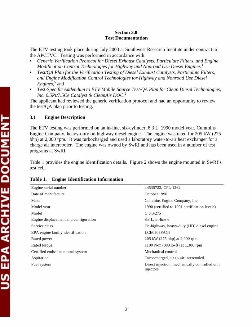
Section 4.0Summary and Discussion of Emission Results
The baseline and controlled emissions data are summarized in Table 5. The emissions were measured at each test point for HC, CO, NOx, and PM. Table 5 also provides data on speciation of the NOx emissions, CO2 emissions, and work. For each pollutant, hot-start test combination, the transient composite-weighted emissions per work (bhp-hr) were then calculated following the fractional calculation for highway engines as follows.
(ECOMP)m = 1/7 • ECOLD + 6/7 • (EHOT)m (1) 1/7 • WCOLD + 6/7 • (WHOT)m
where: m = 1, 2, or 3 hot-start tests ECOMP = composite emissions rate, g/kWh (g/bhp-hr) ECOLD = cold-start mass emissions level, g EHOT = hot-start mass emissions level, g WCOLD = cold-start brake horsepower-hour, kWh (bhp-hr) WHOT = hot-start brake horsepower-hour, kWh (bhp-hr)
These composite-weighted emissions rates are shown in Tables 6 and 7 and were used to calculate the mean and standard deviations for the baseline and controlled emissions rates. These data were in turn used to calculate mean emissions reductions and 95 percent confidence limits. These calculations are based on the generic verification protocol1 and test/QA plan.5
Table 8 summarizes the composite weighted emission values and Table 9 the verified emissions reductions and their 95 percent confidence limits.
9

Table 5. Emissions Test Data
10
Test Number
Test Type
Test Date
Exhaust PM NOX NO NO2 a
NO2/ NOX, %
HC CO CO2 Work, KWh
(bhp-hr) g g
Baseline with LSD fuel
70203-C1 Cold-start 07/02/03 5.53 93.8 75.7 18.1 19.3 8.75 21.1 11.2 14.4 (19.3)
70203-H1 Hot-start 07/02/03 3.43 92.3 75.8 16.5 17.9 7.31 14.3 10.9 14.4 (19.3)
70203-H2 Hot-start 07/02/03 3.34 92.0 75.0 17.0 18.5 7.10 14.2 11.0 14.3 (19.2)
70203-H3 Hot-start 07/02/03 3.27 91.1 74.6 16.5 18.1 7.12 13.8 11.0 14.3 (19.2)
Degreened DOC with FBC-treated ULSD fuel
70703-C1 Cold-start 07/07/03 2.53 85.5 77.4 8.15 9.54 3.83 9.56 11.0 14.1 (18.8)
70703-H1 Hot-start 07/07/03 1.57 84.9 76.4 8.46 9.97 2.88 5.00 10.7 14.2 (19.0)
70703-H3 Hot-start 07/07/03 1.57 82.3 74.3 8.04 9.77 2.91 4.41 10.5 14.1 (18.8)
70703-H4 Hot-start 07/07/03 1.52 84.1 75.7 8.40 9.98 2.85 4.41 10.6 14.2 (19.1)
Aged DOC with FBC-treated ULSD fuel
70903-C1 Cold-start 07/09/03 2.83 90.5 79.0 11.5 12.7 6.01 11.5 11.1 14.1 (18.9)
70903-H1 Hot-start 07/09/03 1.72 85.4 75.4 9.96 11.7 4.65 6.17 10.6 13.8 (18.5)
70903-H2 Hot-start 07/09/03 1.67 86.5 75.2 11.3 13.1 4.12 5.78 10.5 14.0 (18.8)
70903-H3 Hot-start 07/09/03 1.63 87.7 76.0 11.7 13.4 4.05 5.91 10.8 14.1 (18.9)
a NO2 calculated as NOx - NO.

Table 6. Composite Weighted Emissions Values (English units)
11
Test Number
Test Type
Test Date
Exhaust PM NOX NO NO2 a
NO2/ NOX, %
HC CO CO2
g/bhp-hr g/bhp-hr
Baseline with LSD fuel
70203-H1 Hot-start 07/02/03 0.194 4.80 3.93 0.867 18.1 0.390 0.792 570
70203-H2 Hot-start 07/02/03 0.190 4.80 3.91 0.891 18.6 0.382 0.789 572
70203-H3 Hot-start 07/02/03 0.187 4.76 3.89 0.868 18.3 0.383 0.770 572
Degreened DOC with FBC-treated ULSD fuel
70703-H1 Hot-start 07/07/03 0.0897 4.47 4.03 0.443 9.90 0.159 0.297 564
70703-H3 Hot-start 07/07/03 0.0904 4.39 3.96 0.427 9.73 0.161 0.273 562
70703-H4 Hot-start 07/07/03 0.0874 4.42 3.98 0.439 9.92 0.157 0.270 560
Aged DOC with FBC-treated ULSD fuel
70903-H1 Hot-start 07/09/03 0.101 4.65 4.10 0.549 11.8 0.261 0.374 574
70903-H2 Hot-start 07/09/03 0.0974 4.63 4.03 0.603 13.0 0.234 0.351 565
70903-H3 Hot-start 07/09/03 0.0956 4.67 4.05 0.620 13.3 0.229 0.355 574
a NO2 calculated as NOx - NO.
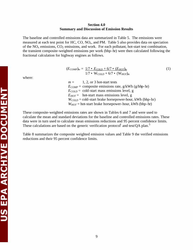
Table 7. Composite Weighted Emissions Values (metric units)
12
Test Number
Test Type
Test Date
Exhaust PM NOX NO NO2 a
NO2/ NOX, %
HC CO CO2
g/kWh g/kWh
Baseline with LSD fuel
70203-H1 Hot-start 07/02/03 0.259 6.40 5.24 1.16 18.1 0.520 1.06 760
70203-H2 Hot-start 07/02/03 0.253 6.40 5.21 1.19 18.6 0.509 1.05 763
70203-H3 Hot-start 07/02/03 0.249 6.35 5.19 1.16 18.3 0.511 1.03 763
Degreened DOC with FBC-treated ULSD fuel
70703-H1 Hot-start 07/07/03 0.120 5.96 5.37 0.591 9.90 0.212 0.396 752
70703-H3 Hot-start 07/07/03 0.121 5.85 5.28 0.569 9.73 0.215 0.364 749
70703-H4 Hot-start 07/07/03 0.117 5.89 5.31 0.585 9.92 0.209 0.360 747
Aged DOC with FBC-treated ULSD fuel
70903-H1 Hot-start 07/09/03 0.135 6.20 5.47 0.732 11.8 0.348 0.499 765
70903-H2 Hot-start 07/09/03 0.130 6.17 5.37 0.804 13.0 0.312 0.468 753
70903-H3 Hot-start 07/09/03 0.127 6.23 5.40 0.827 13.3 0.305 0.473 765
a NO2 calculated as NOx - NO.

Table 8. Summary of Verification Test Emission Values
Device type Fuel
Mean Composite Weighted Emission Value, g/kWh (g/bhp-hr)
PM NOx HC CO CO2
Baseline LSD 0.253 (0.190) 6.37 (4.78) 0.513 (0.385) 1.05 (0.784) 761 (571)
Degreened FBC-treated ULSD
0.119 (0.0892) 5.91 (4.43) 0.212 (0.159) 0.373 (0.280) 749 (562)
Aged FBC-treated ULSD
0.131 (0.0981) 6.20 (4.65) 0.321 (0.241) 0.480 (0.360) 761 (571)
Table 9. Summary of Verification Test Emission Reductions
Device type
Fuel Mean Emissions Reduction (%) 95% Confidence Limits on the
Emissions Reduction (%)
Baseline Controlled PM a NOx HC CO PM a
NOx HC CO
Degreened LSD FBC-treated ULSD
53 7.4 59 64 49-58 5.8-9.1 56-62 60-69
Aged LSD FBC-treated ULSD
48 2.8 37 54 44-53 1.7-3.9 30-45 50-58
a The verified PM emissions reduction combines reductions related to the control technology and the change in fuel sulfur level.
4.1 Quality Assurance
The environmental technology verification of the DOC muffler with FBC-treated ULSD fuel for heavy-duty diesel engines was performed in accordance with the test/QA plan.5 An audit of data quality included the review of equipment, personnel qualifications, procedures, record keeping, data validation, analysis, and reporting. Preliminary, in-process, and final inspections, and a review of 10 percent of the data showed that the requirements stipulated in the test/QA plan5
were achieved. The APCTVC’s quality manager reviewed the test results and the quality control data and concluded that the data quality objectives given in the generic verification protocol were attained. EPA and RTI quality assurance staff conducted audits of SwRI’s technical and quality systems in April 2002 and found no deficiencies that would adversely impact the quality of results. The equipment was appropriate for the verification testing, and it was operating satisfactorily. SwRI’s technical staff were well qualified to perform the testing and conducted themselves in a professional manner.
13
Section 5.0References
1. Research Triangle Institute. Generic Verification Protocol for Diesel Exhaust Catalysts, Particulate Filters, and Engine Modification Control Technologies for Highway and Nonroad Use Diesel Engines. Research Triangle Park, NC, January 2002, http://www.epa.gov/etv/pdfs/vp/05_vp_devrev.pdf.
2. Research Triangle Institute. Test-Specific Addendum to ETV Mobile Source Test/QA Plan for Clean Diesel Technologies, Inc. 0.5Pt/7.5Ce Catalyst & CleanAir DOC. Research Triangle Park, NC, June 2003.
3. Southwest Research Institute. Environmental Technology Verification of CDT’s Fuelborne Catalyst with CleanAir System’s Diesel Oxidation Catalyst Mufflers for Use with Heavy-Duty Diesel Engines. San Antonio, TX, August 2003.
4. Southwest Research Institute. Audit of Data Quality for Environmental Technology Verification of CDT’s Fuel-borne Catalyst with CleanAir System’s Diesel Oxidation Catalyst for Use with Heavy-Duty Diesel Engines. San Antonio, TX, August 2003.
5. Research Triangle Institute. Test/QA Plan for the Verification Testing of Diesel Exhaust Catalysts, Particulate Filters, and Engine Modification Control Technologies for Highway and Nonroad Use Diesel Engines. Research Triangle Park, NC, April 2002, http://www.epa.gov/etv/pdfs/vp/05_tp_diesel.pdf.
6. Fuel specifications, 40 CFR § 86.1313-98, Table N98-2 (updated July 2001).
7. 40 CFR § 86, Subpart N, as of July 1, 1999, http://www.epa.gov/epahome/cfr40.htm.
8. Fuel specifications, 40 CFR § 86.1313-2007, Table N07-2 (updated January 2001).
14