Embed Size (px)
Citation preview

Environmental TestPiezoelectric MEMS Response Accelerometers, Shock Sensors, ForceSensors, Pressure Sensors, Acoustic Microphones & Torque Sensors
Aerospace & Defense Division Toll-Free in USA 866-816-8892 716-684-0001 www.pcb.com
Environmental Test
2 Aerospace & Defense Division Toll-Free in USA 866-816-8892 716-684-0001 www.pcb.com
Environmental Test
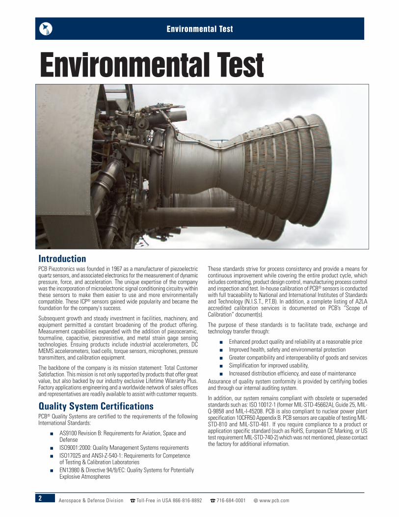
IntroductionPCB Piezotronics was founded in 1967 as a manufacturer of piezoelectricquartz sensors, and associated electronics for the measurement of dynamicpressure, force, and acceleration. The unique expertise of the companywas the incorporation of microelectronic signal conditioning circuitry withinthese sensors to make them easier to use and more environmentallycompatible. These ICP® sensors gained wide popularity and became thefoundation for the company's success.
Subsequent growth and steady investment in facilities, machinery, andequipment permitted a constant broadening of the product offering.Measurement capabilities expanded with the addition of piezoceramic,tourmaline, capacitive, piezoresistive, and metal strain gage sensingtechnologies. Ensuing products include industrial accelerometers, DCMEMS accelerometers, load cells, torque sensors, microphones, pressuretransmitters, and calibration equipment.
The backbone of the company is its mission statement: Total CustomerSatisfaction. This mission is not only supported by products that offer greatvalue, but also backed by our industry exclusive Lifetime Warranty Plus.Factory applications engineering and a worldwide network of sales officesand representatives are readily available to assist with customer requests.
Quality System CertificationsPCB® Quality Systems are certified to the requirements of the followingInternational Standards:
n AS9100 Revision B: Requirements for Aviation, Space andDefense
n ISO9001:2000: Quality Management Systems requirementsn ISO17025 and ANSI-Z-540-1: Requirements for Competence
of Testing & Calibration Laboratoriesn EN13980 & Directive 94/9/EC: Quality Systems for Potentially
Explosive Atmospheres
These standards strive for process consistency and provide a means forcontinuous improvement while covering the entire product cycle, whichincludes contracting, product design control, manufacturing process controland inspection and test. In-house calibration of PCB® sensors is conductedwith full traceability to National and International Institutes of Standardsand Technology (N.I.S.T., P.T.B). In addition, a complete listing of A2LAaccredited calibration services is documented on PCB’s “Scope ofCalibration” document(s).
The purpose of these standards is to facilitate trade, exchange andtechnology transfer through:
n Enhanced product quality and reliability at a reasonable pricen Improved health, safety and environmental protectionn Greater compatibility and interoperability of goods and servicesn Simplification for improved usability,n Increased distribution efficiency, and ease of maintenance
Assurance of quality system conformity is provided by certifying bodiesand through our internal auditing system.
In addition, our system remains compliant with obsolete or supersededstandards such as: ISO 10012-1 (former MIL-STD-45662A), Guide 25, MIL-Q-9858 and MIL-I-45208. PCB is also compliant to nuclear power plantspecification 10CFR50 Appendix B. PCB sensors are capable of testing MIL-STD-810 and MIL-STD-461. If you require compliance to a product orapplication specific standard (such as RoHS, European CE Marking, or UStest requirement MIL-STD-740-2) which was not mentioned, please contactthe factory for additional information.
Environmental Test
3Aerospace & Defense Division Toll-Free in USA 866-816-8892 716-684-0001 www.pcb.com
Environmental Test
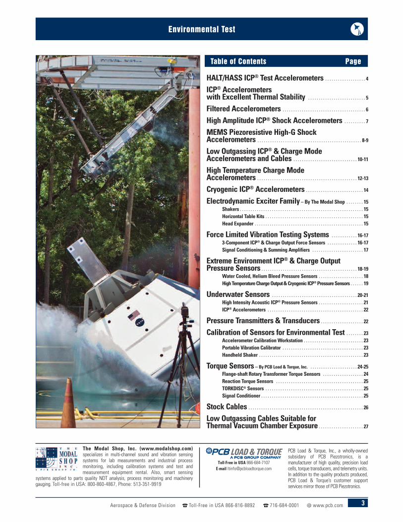
HALT/HASS ICP® Test Accelerometers . . . . . . . . . . . . . . . . . . . 4ICP® Accelerometerswith Excellent Thermal Stability . . . . . . . . . . . . . . . . . . . . . . . . . . . 5Filtered Accelerometers . . . . . . . . . . . . . . . . . . . . . . . . . . . . . . . . . . . . . . . 6High Amplitude ICP® Shock Accelerometers . . . . . . . . . . 7MEMS Piezoresistive High-G ShockAccelerometers . . . . . . . . . . . . . . . . . . . . . . . . . . . . . . . . . . . . . . . . . . . . . . . . . 8-9Low Outgassing ICP® & Charge ModeAccelerometers and Cables . . . . . . . . . . . . . . . . . . . . . . . . . . . . . . 10-11High Temperature Charge ModeAccelerometers . . . . . . . . . . . . . . . . . . . . . . . . . . . . . . . . . . . . . . . . . . . . . . . 12-13Cryogenic ICP® Accelerometers . . . . . . . . . . . . . . . . . . . . . . . . . . . 14Electrodynamic Exciter Family – By The Modal Shop . . . . . . . . 15
Shakers . . . . . . . . . . . . . . . . . . . . . . . . . . . . . . . . . . . . . . . . . . . . . . . . . . . . . . . . . . 15Horizontal Table Kits . . . . . . . . . . . . . . . . . . . . . . . . . . . . . . . . . . . . . . . . . . . . . . 15Head Expander . . . . . . . . . . . . . . . . . . . . . . . . . . . . . . . . . . . . . . . . . . . . . . . . . . . 15
Force Limited Vibration Testing Systems . . . . . . . . . . . . 16-173-Component ICP® & Charge Output Force Sensors . . . . . . . . . . . . . . 16-17Signal Conditioning & Summing Amplifiers . . . . . . . . . . . . . . . . . . . . . . . . 17
Extreme Environment ICP® & Charge OutputPressure Sensors . . . . . . . . . . . . . . . . . . . . . . . . . . . . . . . . . . . . . . . . . . . . . 18-19
Water Cooled, Helium Bleed Pressure Sensors . . . . . . . . . . . . . . . . . . . . . 18High Temperature Charge Output & Cryogenic ICP®Pressure Sensors . . . . . . 19
Underwater Sensors . . . . . . . . . . . . . . . . . . . . . . . . . . . . . . . . . . . . . . . . 20-21High Intensity Acoustic ICP® Pressure Sensors . . . . . . . . . . . . . . . . . . . . . 21ICP® Accelerometers . . . . . . . . . . . . . . . . . . . . . . . . . . . . . . . . . . . . . . . . . . . . . 22
Pressure Transmitters & Transducers . . . . . . . . . . . . . . . . . . . . 22Calibration of Sensors for Environmental Test . . . . . . . . 23
Accelerometer Calibration Workstation . . . . . . . . . . . . . . . . . . . . . . . . . . . . 23Portable Vibration Calibrator . . . . . . . . . . . . . . . . . . . . . . . . . . . . . . . . . . . . . . 23Handheld Shaker . . . . . . . . . . . . . . . . . . . . . . . . . . . . . . . . . . . . . . . . . . . . . . . . . 23
Torque Sensors – By PCB Load & Torque, Inc. . . . . . . . . . . . . . . . . . . . . . . 24-25Flange-shaft Rotary Transformer Torque Sensors . . . . . . . . . . . . . . . . . . . 24Reaction Torque Sensors . . . . . . . . . . . . . . . . . . . . . . . . . . . . . . . . . . . . . . . . . 25TORKDISC® Sensors . . . . . . . . . . . . . . . . . . . . . . . . . . . . . . . . . . . . . . . . . . . . . . 25Signal Conditioner . . . . . . . . . . . . . . . . . . . . . . . . . . . . . . . . . . . . . . . . . . . . . . . . 25
Stock Cables . . . . . . . . . . . . . . . . . . . . . . . . . . . . . . . . . . . . . . . . . . . . . . . . . . . . . . 26Low Outgassing Cables Suitable forThermal Vacuum Chamber Exposure . . . . . . . . . . . . . . . . . . . . . 27
Table of Contents Page
The Modal Shop, Inc. (www.modalshop.com)specializes in multi-channel sound and vibration sensingsystems for lab measurements and industrial processmonitoring, including calibration systems and test andmeasurement equipment rental. Also, smart sensing
systems applied to parts quality NDT analysis, process monitoring and machinerygauging. Toll-free in USA: 800-860-4867, Phone: 513-351-9919
Toll-Free in USA 866-684-7107E-mail [email protected]
PCB Load & Torque, Inc., a wholly-ownedsubsidary of PCB Piezotronics, is amanufacturer of high quality, precision loadcells, torque transducers, and telemetry units.In addition to the quality products produced,PCB Load & Torque’s customer supportservices mirror those of PCB Piezotronics.
HALT/HASS Test Accelerometers
Model Number 320C03 320C04 320C15 320C20 320C33
Performance
Sensitivity (± 10 %) 10 mV/g1.02 mV/(m/s²)
10 mV/g1.02 mV/(m/s²)
10 mV/g1.02 mV/(m/s²)
10 mV/g1.02 mV/(m/s²)
100 mV/g10.2 mV/(m/s²)
Measurement Range ± 500 g pk±4900 m/s² pk
± 500 g pk±4900 m/s² pk
± 500 g pk±4900 m/s² pk
± 500 g pk±4900 m/s² pk
± 50 g pk± 490 m/s² pk
Frequency Range (± 5 %) 1 to 6000 Hz 1 to 6000 Hz 1.0 to 10,000 Hz 2.0 to 5000 Hz 1 to 4000 Hz
Resonant Frequency ≥ 35 kHz ≥ 35 kHz ≥ 60 kHz ≥ 60 kHz ≥ 22 kHz
Broadband Resolution (1 to 10,000 Hz) 0.003 g rms0.03 m/s² rms
0.003 g rms0.03 m/s² rms
0.005 g rms0.05 m/s² rms
0.006 g rms0.06 m/s² rms
0.0003 g rms0.003 m/s² rms
Filter Type — — — Low Pass —
Electrical Filter Corner Frequency — — — 13 kHz —
Electrical Filter Roll-off — — — 6 dB/octave —
Environmental
Overload Limit (Shock) ± 10,000 g pk± 98,100 m/s² pk
± 10,000 g pk± 98,100 m/s² pk
± 10,000 g pk± 98,100 m/s² pk
± 10,000 g pk± 98,100 m/s² pk
± 2000 g pk± 19,620 m/s² pk
Temperature Range (Operating) -100 to +325 °F-73 to +163 °C
-100 to +325 °F-73 to +163 °C
-100 to +325 °F-73 to +163 °C
-100 to +325 °F-73 to +163 °C
-100 to +325 °F-73 to +163 °C
Physical
Size (Height x Hex) 0.81 in x 0.50 in20.6 mm x 12.7 mm
1.14 in x 0.50 in29.0 mm x 12.7 mm
0.43 in x 5/16 in10.9 mm x 5/16 in
0.87 in x 0.38 in22.1 mm x 9.7
0.85 in x 0.75 in21.6 mm x 19.1 mm
Weight 0.38 oz10.5 gm
0.38 oz10.5 gm
0.07 oz2.0 gm
0.23 oz6.5 gm
0.7 oz20 gm
Sensing Element Quartz Quartz Quartz Quartz Quartz
Sensing Geometry Shear Shear Shear Shear Shear
Housing Material Titanium Titanium Titanium Titanium Titanium
Electrical Connector 10-32 Coaxial Jack 10-32 Coaxial Jack 5-44 Coaxial 10-32 Coaxial Jack 10-32 Coaxial Jack
Electrical Connector Position Side Top Side Top Side
Mounting Thread 10-32 Female 10-32 Female 5-40 Male 10-32 Male 10-32 Female
4 Aerospace & Defense Division Toll-Free in USA 866-816-8892 716-684-0001 www.pcb.com
Environmental Test
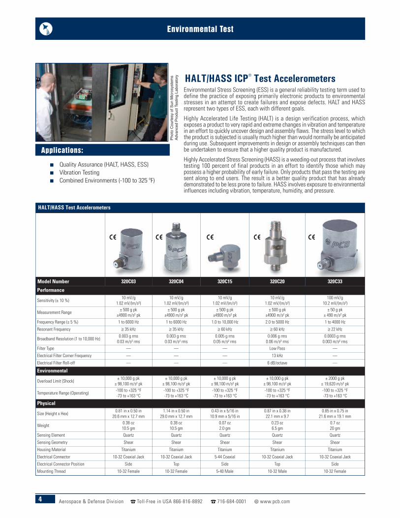
Environmental Stress Screening (ESS) is a general reliability testing term used todefine the practice of exposing primarily electronic products to environmentalstresses in an attempt to create failures and expose defects. HALT and HASSrepresent two types of ESS, each with different goals.
Highly Accelerated Life Testing (HALT) is a design verification process, whichexposes a product to very rapid and extreme changes in vibration and temperaturein an effort to quickly uncover design and assembly flaws. The stress level to whichthe product is subjected is usually much higher than would normally be anticipatedduring use. Subsequent improvements in design or assembly techniques can thenbe undertaken to ensure that a higher quality product is manufactured.
Highly Accelerated Stress Screening (HASS) is a weeding-out process that involvestesting 100 percent of final products in an effort to identify those which maypossess a higher probability of early failure. Only products that pass the testing aresent along to end users. The result is a better quality product that has alreadydemonstrated to be less prone to failure. HASS involves exposure to environmentalinfluences including vibration, temperature, humidity, and pressure.
HALT/HASS ICP® Test Accelerometers
Applications:
n Quality Assurance (HALT, HASS, ESS)n Vibration Testingn Combined Environments (-100 to 325 ºF)
Phot
o Co
urte
sy o
f Sun
Micr
osys
tem
sAd
vanc
ed P
rodu
ct Te
sting
Lab
orat
ory
5Aerospace & Defense Division Toll-Free in USA 866-816-8892 716-684-0001 www.pcb.com
Environmental Test
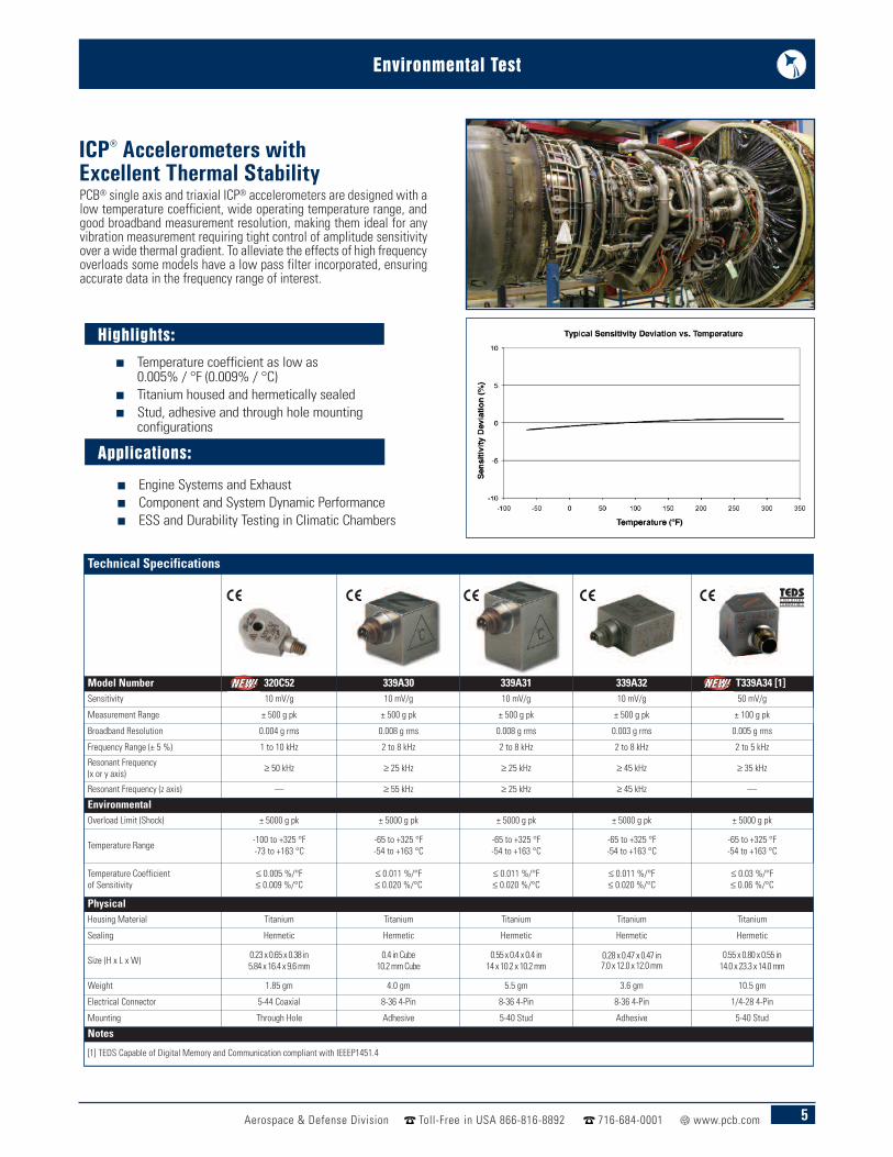
ICP® Accelerometers withExcellent Thermal Stability
Highlights:
n Temperature coefficient as low as0.005% / °F (0.009% / °C)
n Titanium housed and hermetically sealed n Stud, adhesive and through hole mounting
configurations
Applications:
n Engine Systems and Exhaust n Component and System Dynamic Performancen ESS and Durability Testing in Climatic Chambers
PCB® single axis and triaxial ICP® accelerometers are designed with alow temperature coefficient, wide operating temperature range, andgood broadband measurement resolution, making them ideal for anyvibration measurement requiring tight control of amplitude sensitivityover a wide thermal gradient. To alleviate the effects of high frequencyoverloads some models have a low pass filter incorporated, ensuringaccurate data in the frequency range of interest.
Technical Specifications
Model Number 320C52 339A30 339A31 339A32 T339A34 [1]Sensitivity 10 mV/g 10 mV/g 10 mV/g 10 mV/g 50 mV/g
Measurement Range ± 500 g pk ± 500 g pk ± 500 g pk ± 500 g pk ± 100 g pk
Broadband Resolution 0.004 g rms 0.008 g rms 0.008 g rms 0.003 g rms 0.005 g rms
Frequency Range (± 5 %) 1 to 10 kHz 2 to 8 kHz 2 to 8 kHz 2 to 8 kHz 2 to 5 kHz
Resonant Frequency (x or y axis) ≥ 50 kHz ≥ 25 kHz ≥ 25 kHz ≥ 45 kHz ≥ 35 kHz
Resonant Frequency (z axis) — ≥ 55 kHz ≥ 25 kHz ≥ 45 kHz —
EnvironmentalOverload Limit (Shock) ± 5000 g pk ± 5000 g pk ± 5000 g pk ± 5000 g pk ± 5000 g pk
Temperature Range -100 to +325 °F-73 to +163 °C
-65 to +325 °F-54 to +163 °C
-65 to +325 °F-54 to +163 °C
-65 to +325 °F-54 to +163 °C
-65 to +325 °F-54 to +163 °C
Temperature Coefficient of Sensitivity
≤ 0.005 %/°F≤ 0.009 %/°C
≤ 0.011 %/°F≤ 0.020 %/°C
≤ 0.011 %/°F≤ 0.020 %/°C
≤ 0.011 %/°F≤ 0.020 %/°C
≤ 0.03 %/°F≤ 0.06 %/°C
PhysicalHousing Material Titanium Titanium Titanium Titanium Titanium
Sealing Hermetic Hermetic Hermetic Hermetic Hermetic
Size (H x L x W) 0.23 x 0.65 x 0.38 in5.84 x 16.4 x 9.6 mm
0.4 in Cube10.2 mm Cube
0.55 x 0.4 x 0.4 in14 x 10.2 x 10.2 mm
0.28 x 0.47 x 0.47 in7.0 x 12.0 x 12.0 mm
0.55 x 0.80 x 0.55 in14.0 x 23.3 x 14.0 mm
Weight 1.85 gm 4.0 gm 5.5 gm 3.6 gm 10.5 gm
Electrical Connector 5-44 Coaxial 8-36 4-Pin 8-36 4-Pin 8-36 4-Pin 1/4-28 4-Pin
Mounting Through Hole Adhesive 5-40 Stud Adhesive 5-40 Stud
Notes
[1] TEDS Capable of Digital Memory and Communication compliant with IEEEP1451.4
6 Aerospace & Defense Division Toll-Free in USA 866-816-8892 716-684-0001 www.pcb.com
Environmental Test
Filtered ICP® Accelerometers
Filtered Accelerometers
Model Number 352B70 352A72 356A63 356A66
Performance
Sensitivity(± 15 %) 1 mV/g0.1 mV/(m/s²)
10 mV/g1.02 mV/(m/s²)
10 mV/g1.02 mV/(m/s²)
10 mV/g1.02 mV/(m/s²) (± 10 %)
Measurement Range ± 5000 g pk± 49,000 m/s² pk
± 500 g pk± 4905 m/s² pk
± 500 g pk± 4905 m/s² pk
± 500 g pk± 4905 m/s² pk
Frequency Range(± 5 %) 0.7 to 9000 Hz 0.5 to 4500 Hz 2 to 4000 Hz 2 to 4000 Hz
Electrical Filter Corner Frequency 23 kHz 15 kHz 15 kHz 16 kHz
Electrical Filter Roll-off 12 dB/octave 6 dB/octave 6 dB/octave 6 dB/octave
Resonant Frequency ≥ 55 kHz ≥ 65 kHz ≥ 55 kHz ≥ 35 kHzBroadband Resolution(1 to 10,000 Hz)
0.025 g rms0.25 m/s² rms
0.003 g rms0.03 m/s² rms
0.008 g rms0.08 m/s² rms
0.002 g rms0.02 m/s² rms
Environmental
Overload Limit (Shock) ± 10,000 g pk± 98,000 m/s² pk
± 10,000 g pk± 98,000 m/s² pk
± 10,000 g pk± 98,000 m/s² pk
± 10,000 g pk± 98,000 m/s² pk
Temperature Range (Operating) -65 to +250 °F-54 to +121 °C
-65 to +250 °F-54 to +121 °C
-65 to +250 °F-54 to +121 °C
-65 to +250 °F-54 to +121 °C
Physical
Size (Height x Length x Width) 0.90 x 3/8 in22.9 mm x 3/8 in (Height x Hex)
0.14 in x 0.41 in x 0.25 in3.6 mm x 10.4 mm x 6.4 mm
0.40 in x 0.77 in x 0.40 in10.2 mm x 19.6 mm x 10.2 mm
0.55 in x 0.80 in x 0.55 in 14.0 mm x 20.3 mm x 14.0 mm
Weight (without cable) 0.15 oz4.3 gm
0.023 oz0.64 gm
0.19 oz5.3 gm
0.32 oz9.0 gm
Sensing Element Ceramic Ceramic Ceramic Ceramic
Sensing Geometry Shear Shear Shear Shear
Housing Material Titanium Titanium Titanium Titanium
Electrical Connector 10-32 Coaxial Jack Solder pins, 10 ft. attachedcable, 10-32 plug 1/4-28 4-Pin 1/4-28 4-Pin
Electrical Connector Position Top Side Side Side
Mounting Thread 10-32 Female Adhesive 5-40 Female 10-32 Female
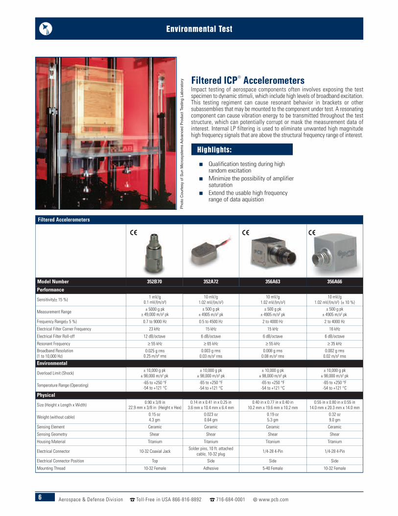
Impact testing of aerospace components often involves exposing the testspecimen to dynamic stimuli, which include high levels of broadband excitation.This testing regiment can cause resonant behavior in brackets or othersubassemblies that may be mounted to the component under test. A resonatingcomponent can cause vibration energy to be transmitted throughout the teststructure, which can potentially corrupt or mask the measurement data ofinterest. Internal LP filtering is used to eliminate unwanted high magnitudehigh frequency signals that are above the structural frequency range of interest.
Highlights:
n Qualification testing during highrandom excitation
n Minimize the possibility of amplifiersaturation
n Extend the usable high frequencyrange of data aquistion
Phot
o Co
urte
sy o
f Sun
Micr
osys
tem
s Adv
ance
d Pr
oduc
t Tes
ting
Labo
rato
ry
7Aerospace & Defense Division Toll-Free in USA 866-816-8892 716-684-0001 www.pcb.com
Environmental Test
High Amplitude ICP® Shock Accelerometers
High Amplitude ICP® Shock Response Accelerometers
Single Axis Triaxial
Model Number 350C23 350D02 350B21 350B50
Performance
Sensitivity (± 30 %) 0.5 mV/g0.05 mV/(m/s²)
0.1 mV/g0.01 mV/(m/s²)
0.05 mV/g0.005 mV/(m/s²)
0.5 mV/g0.05 mV/(m/s²)
Measurement Range ± 10,000 g pk± 98,000 m/s² pk
± 50,000 g pk± 490,000 m/s² pk
± 100,000 g pk± 980,000 m/s² pk
± 10,000 g pk± 98,000 m/s² pk
Frequency Range (± 1 dB) 0.4 to 10,000 Hz 4 to 10,000 Hz 1 to 10,000 Hz 3 to 10,000 Hz
Frequency Range (-3 dB) 0.2 to 25,000 Hz 2 to 25,000 Hz 0.5 to 35,000 Hz 1.5 to 20,000 Hz
Electrical Filter Corner Frequency (-3 dB) 13 kHz 17 kHz NA 20 kHz
Mechanical Filter Resonant Frequency 23 kHz 45 kHz NA NA
Resonant Frequency ≥ 100 kHz ≥ 100 kHz ≥ 200 kHz ≥ 60 kHz
Environmental
Overload Limit (Shock) ± 50,000 g pk± 490,000 m/s² pk
± 150,000 g pk± 1,471,500 m/s² pk
± 200,000 g pk± 1,960,000 m/s² pk
± 25,000 g pk± 245,000 m/s² pk
Temperature Range (Operating) 0 to +150 °F-18 to +66 °C
0 to +150 °F-18 to +66 °C
-65 to +200 °F-54 to +93 °C
-65 to +250 °F-54 to +121 °C
Physical
Sensing Element Ceramic Ceramic Ceramic Ceramic
Sensing Geometry Shear Shear Shear Shear
Sealing Hermetic Hermetic Hermetic Hermetic
Housing Material Titanium Titanium Titanium Titanium
Size (Hex x Height) 0.375 in x 0.75 in9.5 mm x 19.1 mm
0.375 in x 0.87 in9.5 mm x 19.1 mm
0.375 in x 0.75 in9.5 mm x 19.1 mm
0.32 in x 0.72 in x 0.72 in8.2 mm x 18.3 mm x 18.3 mm(Height x Length x Width)
Weight 0.16 oz 4.5 gm 0.15 oz 4.2 gm 0.15 oz 4.2 gm 0.3 oz 8.0 gm
Electrical Connector Integral Cable Integral Cable Integral Cable Integral Cable
Cable Length 10 ft3.05 m
10 ft3.05 m
10 ft3.05 m
5.0 ft1.52 m
Mounting Thread 1/4-28 Male 1/4-28 Male 1/4-28 Male Through Hole
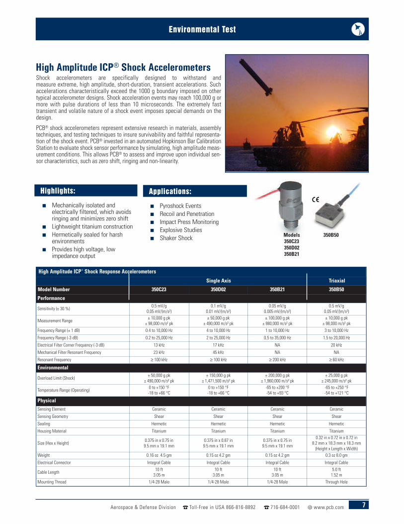
Models350C23350D02350B21
Shock accelerometers are specifically designed to withstand andmeasure extreme, high amplitude, short-duration, transient accelerations. Suchaccelerations characteristically exceed the 1000 g boundary imposed on othertypical accelerometer designs. Shock acceleration events may reach 100,000 g ormore with pulse durations of less than 10 microseconds. The extremely fasttransient and volatile nature of a shock event imposes special demands on thedesign.
PCB® shock accelerometers represent extensive research in materials, assemblytechniques, and testing techniques to insure survivability and faithful representa-tion of the shock event. PCB® invested in an automated Hopkinson Bar CalibrationStation to evaluate shock sensor performance by simulating, high amplitude meas-urement conditions. This allows PCB® to assess and improve upon individual sen-sor characteristics, such as zero shift, ringing and non-linearity.
Highlights:
n Mechanically isolated andelectrically filtered, which avoidsringing and minimizes zero shift
n Lightweight titanium construction n Hermetically sealed for harsh
environments n Provides high voltage, low
impedance output
Applications:
n Pyroshock Eventsn Recoil and Penetrationn Impact Press Monitoringn Explosive Studiesn Shaker Shock 350B50
8 Aerospace & Defense Division Toll-Free in USA 866-816-8892 716-684-0001 www.pcb.com
Environmental Test
MEMS High-G Shock AccelerometersSurface Mount Packaged
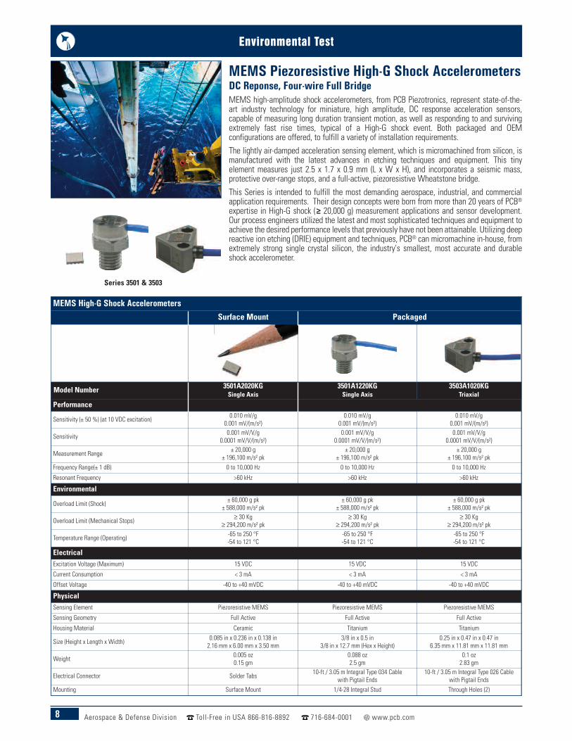
Model Number 3501A2020KGSingle Axis
3501A1220KGSingle Axis
3503A1020KGTriaxial
Performance
Sensitivity (± 50 %) (at 10 VDC excitation) 0.010 mV/g0.001 mV/(m/s²)
0.010 mV/g0.001 mV/(m/s²)
0.010 mV/g0.001 mV/(m/s²)
Sensitivity 0.001 mV/V/g0.0001 mV/V/(m/s²)
0.001 mV/V/g0.0001 mV/V/(m/s²)
0.001 mV/V/g0.0001 mV/V/(m/s²)
Measurement Range ± 20,000 g± 196,100 m/s² pk
± 20,000 g± 196,100 m/s² pk
± 20,000 g± 196,100 m/s² pk
Frequency Range(± 1 dB) 0 to 10,000 Hz 0 to 10,000 Hz 0 to 10,000 Hz
Resonant Frequency >60 kHz >60 kHz >60 kHz
Environmental
Overload Limit (Shock) ± 60,000 g pk± 588,000 m/s² pk
± 60,000 g pk± 588,000 m/s² pk
± 60,000 g pk± 588,000 m/s² pk
Overload Limit (Mechanical Stops) ≥ 30 Kg≥ 294,200 m/s² pk
≥ 30 Kg≥ 294,200 m/s² pk
≥ 30 Kg≥ 294,200 m/s² pk
Temperature Range (Operating) -65 to 250 °F-54 to 121 °C
-65 to 250 °F-54 to 121 °C
-65 to 250 °F-54 to 121 °C
ElectricalExcitation Voltage (Maximum) 15 VDC 15 VDC 15 VDC
Current Consumption < 3 mA < 3 mA < 3 mA
Offset Voltage -40 to +40 mVDC -40 to +40 mVDC -40 to +40 mVDC
PhysicalSensing Element Piezoresistive MEMS Piezoresistive MEMS Piezoresistive MEMS
Sensing Geometry Full Active Full Active Full Active
Housing Material Ceramic Titanium Titanium
Size (Height x Length x Width) 0.085 in x 0.236 in x 0.138 in2.16 mm x 6.00 mm x 3.50 mm
3/8 in x 0.5 in3/8 in x 12.7 mm (Hex x Height)
0.25 in x 0.47 in x 0.47 in6.35 mm x 11.81 mm x 11.81 mm
Weight 0.005 oz0.15 gm
0.088 oz2.5 gm
0.1 oz2.83 gm
Electrical Connector Solder Tabs 10-ft / 3.05 m Integral Type 034 Cablewith Pigtail Ends
10-ft / 3.05 m Integral Type 026 Cablewith Pigtail Ends
Mounting Surface Mount 1/4-28 Integral Stud Through Holes (2)
MEMS Piezoresistive High-G Shock AccelerometersDC Reponse, Four-wire Full BridgeMEMS high-amplitude shock accelerometers, from PCB Piezotronics, represent state-of-the-art industry technology for miniature, high amplitude, DC response acceleration sensors,capable of measuring long duration transient motion, as well as responding to and survivingextremely fast rise times, typical of a High-G shock event. Both packaged and OEMconfigurations are offered, to fulfill a variety of installation requirements.
The lightly air-damped acceleration sensing element, which is micromachined from silicon, ismanufactured with the latest advances in etching techniques and equipment. This tinyelement measures just 2.5 x 1.7 x 0.9 mm (L x W x H), and incorporates a seismic mass,protective over-range stops, and a full-active, piezoresistive Wheatstone bridge.
This Series is intended to fulfill the most demanding aerospace, industrial, and commercialapplication requirements. Their design concepts were born from more than 20 years of PCB®expertise in High-G shock (≥ 20,000 g) measurement applications and sensor development.Our process engineers utilized the latest and most sophisticated techniques and equipment toachieve the desired performance levels that previously have not been attainable. Utilizing deepreactive ion etching (DRIE) equipment and techniques, PCB® can micromachine in-house, fromextremely strong single crystal silicon, the industry's smallest, most accurate and durableshock accelerometer.
Series 3501 & 3503
9Aerospace & Defense Division Toll-Free in USA 866-816-8892 716-684-0001 www.pcb.com
Environmental Test
MEMS High-G Shock AccelerometersSurface Mount Packaged
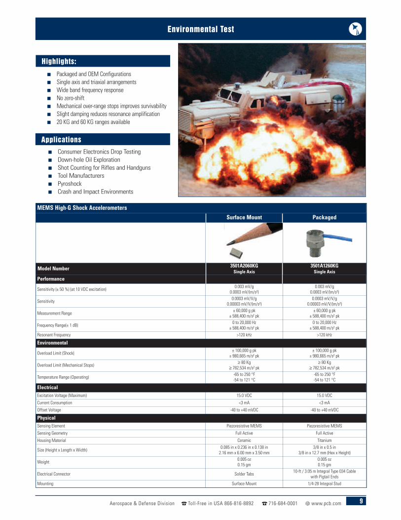
Model Number 3501A2060KGSingle Axis
3501A1260KGSingle Axis
Performance
Sensitivity (± 50 %) (at 10 VDC excitation) 0.003 mV/g 0.0003 mV/(m/s²)
0.003 mV/g0.0003 mV/(m/s²)
Sensitivity 0.0003 mV/V/g0.00003 mV/V/(m/s²)
0.0003 mV/V/g0.00003 mV/V/(m/s²)
Measurement Range ± 60,000 g pk± 588,400 m/s² pk
± 60,000 g pk± 588,400 m/s² pk
Frequency Range(± 1 dB) 0 to 20,000 Hz± 588,400 m/s² pk
0 to 20,000 Hz± 588,400 m/s² pk
Resonant Frequency >120 kHz >120 kHz
Environmental
Overload Limit (Shock) ± 100,000 g pk ± 980,665 m/s² pk
± 100,000 g pk± 980,665 m/s² pk
Overload Limit (Mechanical Stops) ≥ 80 Kg≥ 782,534 m/s² pk
≥ 80 Kg≥ 782,534 m/s² pk
Temperature Range (Operating) -65 to 250 °F-54 to 121 °C
-65 to 250 °F-54 to 121 °C
ElectricalExcitation Voltage (Maximum) 15.0 VDC 15.0 VDC
Current Consumption <3 mA <3 mA
Offset Voltage -40 to +40 mVDC -40 to +40 mVDC
PhysicalSensing Element Piezoresistive MEMS Piezoresistive MEMS
Sensing Geometry Full Active Full Active
Housing Material Ceramic Titanium
Size (Height x Length x Width) 0.085 in x 0.236 in x 0.138 in2.16 mm x 6.00 mm x 3.50 mm
3/8 in x 0.5 in3/8 in x 12.7 mm (Hex x Height)
Weight 0.005 oz0.15 gm
0.005 oz0.15 gm
Electrical Connector Solder Tabs 10-ft / 3.05 m Integral Type 034 Cablewith Pigtail Ends
Mounting Surface Mount 1/4-28 Integral Stud
Applicationsn Consumer Electronics Drop Testing n Down-hole Oil Explorationn Shot Counting for Rifles and Handgunsn Tool Manufacturers n Pyroshock n Crash and Impact Environments
n Packaged and OEM Configurationsn Single axis and triaxial arrangementsn Wide band frequency responsen No zero-shift n Mechanical over-range stops improves survivabilityn Slight damping reduces resonance amplificationn 20 KG and 60 KG ranges available
Highlights:
10 Aerospace & Defense Division Toll-Free in USA 866-816-8892 716-684-0001 www.pcb.com
Environmental Test
Low Outgassing ICP® & Charge Mode Accelerometers
Model Number 350M72 352M212 357A07 357A09
Performance
Sensitivity (± 10 %) 0.5 mV/g0.05 mV/(m/s²)
10 mV/g1.02 mV/(m/s²)
1.7 pC/g0.17 pC/(m/s²) (± 20 %)
1.7 pC/g0.17 pC/(m/s²) (± 20 %)
Measurement Range ± 10,000 g pk± 98,000 m/s² pk
± 500 g pk± 4905 m/s² pk
± 2000 g pk± 19,620 m/s² pk
± 2000 g pk± 19,620 m/s² pk
Frequency Range (± 1 dB) 0.4 to 10,000 Hz 0.5 to 10,000 Hz (± 5 %) 15,000 Hz (+5 %) 10,000 Hz (+5 %)
Resonant Frequency ≥ 100 kHz ≥ 65 kHz ≥ 60 kHz ≥ 50 kHz
Environmental
Overload Limit (Shock) ± 50,000 g pk± 490,000 m/s² pk
± 10,000 g pk± 98,100 m/s² pk
± 10,000 g pk± 98,100 m/s² pk
± 10,000 g pk± 98,100 m/s² pk
Temperature Range (Operating) 0 to +150 °F-18 to +66 °C
-65 to +250 °F-54 to +121 °C
-100 to 500 °F-73 to 260 °C
-100 to 350 °F-73 to 177 °C
PhysicalSensing Element Ceramic Ceramic Ceramic Ceramic
Sensing Geometry Shear Shear Shear Shear
Sealing Hermetic Hermetic Hermetic Hermetic
Housing Material Titanium Titanium Titanium Titanium
Size (Height x Length x Width) 0.375 in x 0.95 in9.5 mm x 24.1 mm (Hex x Height)
0.14 in x 0.41 in x 0.25 in3.6 mm x 10.4 mm x 6.4 mm
0.195 in x 0.420 in x 0.250 in4.9 mm x 10.7 mm x 6.4 mm
0.14 in x 0.45 in x 0.25 in3.6 mm x 11.4 mm x 6.4 mm
Weight 0.17 oz4.8 gm
0.023 oz0.64 gm
0.03 oz0.7 gm
0.02 oz0.6 gm
Mounting 1/4-28 Male Adhesive Adhesive Adhesive
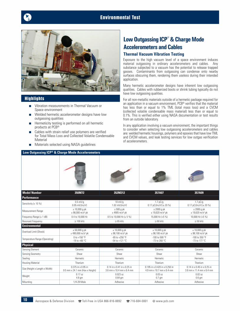
Low Outgassing ICP® & Charge ModeAccelerometers and CablesThermal Vacuum Vibration TestingExposure to the high vacuum level of a space environment inducesmaterial outgassing in ordinary accelerometers and cables. Anysubstance subjected to a vacuum has the potential to release trappedgasses. Contaminants from outgassing can condense onto nearbysurfaces obscuring them, rendering them useless during their intendedapplication.
Many hermetic accelerometer designs have inherent low outgassingqualities. Cables with rubberized boots or shrink tubing typically do nothave low outgassing qualities.
For all non-metallic materials outside of a hermetic package required foran application in a vacuum environment, PCB® verifies that the materialhas less than or equal to 1% TML (total mass loss) and a CVCM(collected volatile condensable mass material) less than or equal to0.1%. This is verified either using NASA documentation or test resultsfrom an outside laboratory.
In any application involving a vacuum environment, the important thingsto consider when selecting low outgassing accelerometers and cablesare: welded hermetic housings, polymers and epoxies that have low TMLand CVCM values, and leak testing services for low outgas verificationof accelerometers.
Highlightsn Vibration measurements in Thermal Vacuum or
Space environmentn Welded hermetic accelerometer designs have low
outgassing qualitiesn Hermeticity testing is performed on all hermetic
products at PCB®
n Cables with strain relief use polymers are verifiedfor Total Mass Loss and Collected Volatile CondensableMaterial
n Materials selected using NASA guidelines
11Aerospace & Defense Division Toll-Free in USA 866-816-8892 716-684-0001 www.pcb.com
Environmental Test
Low Outgassing ICP® Accelerometers
Model Number 356M208 356M57 356M132 356M98
Performance
Sensitivity (± 20 %) 5 mV/g0.51 mV/(m/s²)
10 mV/g1.02 mV/(m/s²) (± 10 %)
500 mV/g51 mV/(m/s²) (± 10 %)
1000 mV/g102 mV/(m/s²) (± 10 %)
Measurement Range ± 1000 g pk± 9810 m/s² pk
± 500 g pk± 4905 m/s² pk
± 10 g pk± 98 m/s² pk
± 5 g pk± 49 m/s² pk
Frequency Range (± 5 %) (y or z axis) 2 to 8000 Hz 2 to 10,000 Hz 0.5 to 3000 Hz 0.5 to 3000 Hz
Resonant Frequency ≥ 50 kHz ≥ 55 kHz ≥ 14 kHz ≥ 20 kHz
Environmental
Overload Limit (Shock) ± 10,000 g pk± 98,100 m/s² pk
± 10,000 g pk± 98,100 m/s² pk
± 5000 g pk± 49,000 m/s² pk
± 5000 g pk± 49,000 m/s² pk
Temperature Range (Operating) -65 to +250 °F-54 to +121 °C
-65 to +250 °F-54 to +121 °C
-65 to +176 °F-54 to +80 °C
-20 to +170 °F-29 to +77 °C
ElectricalExcitation Voltage 18 to 30 VDC 18 to 30 VDC 18 to 30 VDC 20 to 30 VDC
Output Impedance ≤ 200 Ohm ≤ 200 Ohm ≤ 300 Ohm ≤ 600 OhmOutput Bias Voltage 7 to 11 VDC 7 to 11 VDC 8 to 12 VDC 8 to 12 VDC
Physical
Sensing Element Ceramic Ceramic Ceramic Ceramic
Sensing Geometry Shear Shear Shear Shear
Housing Material Titanium Titanium Titanium Titanium
Size (Height x Length x Width) 0.25 in x 0.25 in x 0.25 in6.35 mm x 6.35 mm x 6.35 mm
0.4 in x 0.4 in x 0.4 in10.2 mm x 10.2 mm x 10.2 mm
0.55 in x 0.80 in x 0.55 in14.0 mm x 20.3 mm x 14.0 mm
0.80 in x 1.03 in x 0.80 in20.3 mm x 26.1 mm x 20.3 mm
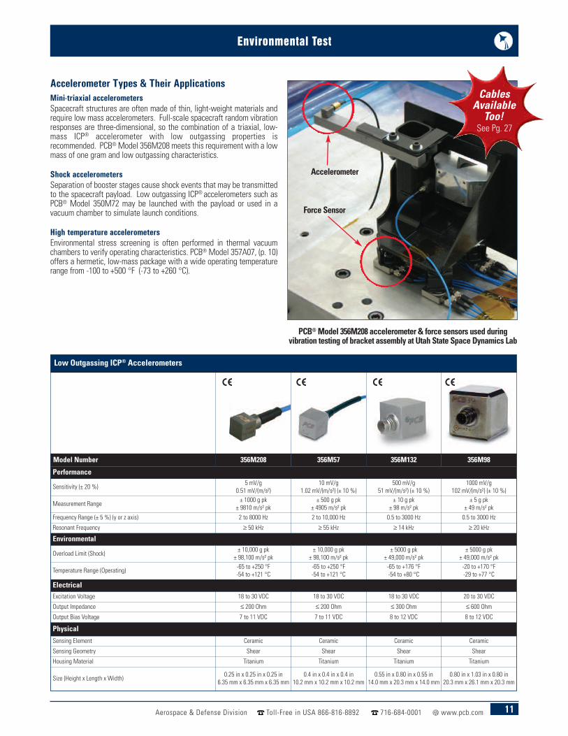
Mini-triaxial accelerometersSpacecraft structures are often made of thin, light-weight materials andrequire low mass accelerometers. Full-scale spacecraft random vibrationresponses are three-dimensional, so the combination of a triaxial, low-mass ICP® accelerometer with low outgassing properties isrecommended. PCB®Model 356M208 meets this requirement with a lowmass of one gram and low outgassing characteristics.
Shock accelerometersSeparation of booster stages cause shock events that may be transmittedto the spacecraft payload. Low outgassing ICP® accelerometers such asPCB® Model 350M72 may be launched with the payload or used in avacuum chamber to simulate launch conditions.
High temperature accelerometersEnvironmental stress screening is often performed in thermal vacuumchambers to verify operating characteristics. PCB® Model 357A07, (p. 10)offers a hermetic, low-mass package with a wide operating temperaturerange from -100 to +500 °F (-73 to +260 °C).
CablesAvailable
Too!See Pg. 27
PCB®Model 356M208 accelerometer & force sensors used duringvibration testing of bracket assembly at Utah State Space Dynamics Lab
Accelerometer
Force Sensor
Accelerometer Types & Their Applications
12 Aerospace & Defense Division Toll-Free in USA 866-816-8892 716-684-0001 www.pcb.com
Environmental Test
High Temperature Charge Mode Accelerometers
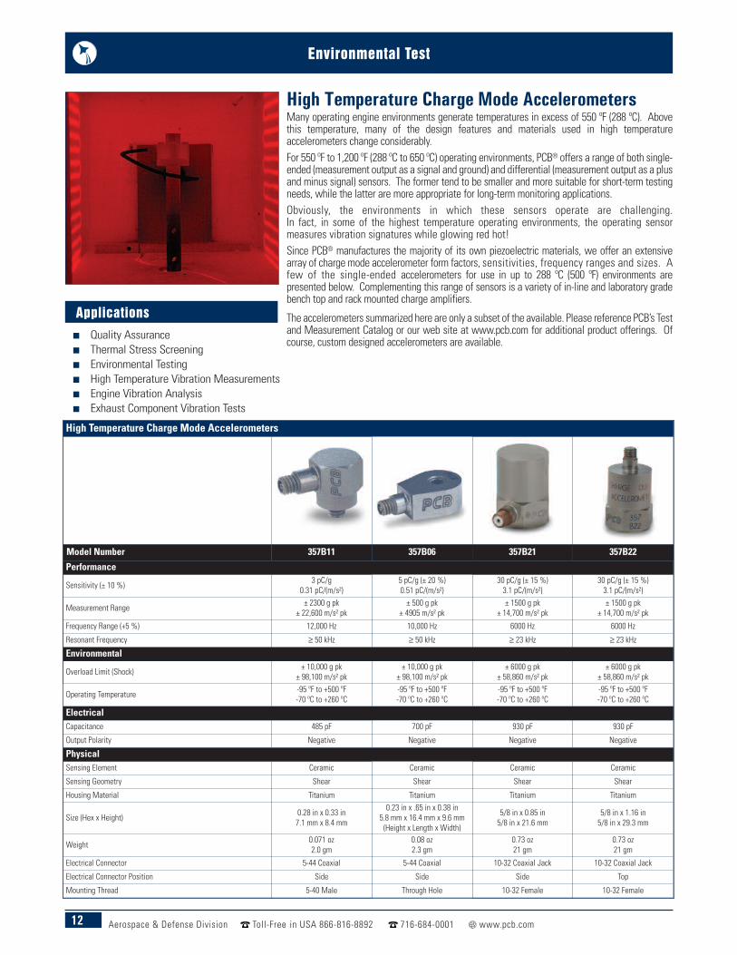
Model Number 357B11 357B06 357B21 357B22
Performance
Sensitivity (± 10 %) 3 pC/g0.31 pC/(m/s²)
5 pC/g (± 20 %)0.51 pC/(m/s²)
30 pC/g (± 15 %)3.1 pC/(m/s²)
30 pC/g (± 15 %)3.1 pC/(m/s²)
Measurement Range ± 2300 g pk± 22,600 m/s² pk
± 500 g pk± 4905 m/s² pk
± 1500 g pk± 14,700 m/s² pk
± 1500 g pk± 14,700 m/s² pk
Frequency Range (+5 %) 12,000 Hz 10,000 Hz 6000 Hz 6000 Hz
Resonant Frequency ≥ 50 kHz ≥ 50 kHz ≥ 23 kHz ≥ 23 kHz
Environmental
Overload Limit (Shock) ± 10,000 g pk± 98,100 m/s² pk
± 10,000 g pk± 98,100 m/s² pk
± 6000 g pk± 58,860 m/s² pk
± 6000 g pk± 58,860 m/s² pk
Operating Temperature -95 ºF to +500 ºF-70 ºC to +260 ºC
-95 ºF to +500 ºF-70 ºC to +260 ºC
-95 ºF to +500 ºF-70 ºC to +260 ºC
-95 ºF to +500 ºF-70 ºC to +260 ºC
ElectricalCapacitance 485 pF 700 pF 930 pF 930 pF
Output Polarity Negative Negative Negative Negative
PhysicalSensing Element Ceramic Ceramic Ceramic Ceramic
Sensing Geometry Shear Shear Shear Shear
Housing Material Titanium Titanium Titanium Titanium
Size (Hex x Height) 0.28 in x 0.33 in7.1 mm x 8.4 mm
0.23 in x .65 in x 0.38 in5.8 mm x 16.4 mm x 9.6 mm (Height x Length x Width)
5/8 in x 0.85 in5/8 in x 21.6 mm
5/8 in x 1.16 in5/8 in x 29.3 mm
Weight 0.071 oz2.0 gm
0.08 oz2.3 gm
0.73 oz21 gm
0.73 oz21 gm
Electrical Connector 5-44 Coaxial 5-44 Coaxial 10-32 Coaxial Jack 10-32 Coaxial Jack
Electrical Connector Position Side Side Side Top
Mounting Thread 5-40 Male Through Hole 10-32 Female 10-32 Female
Many operating engine environments generate temperatures in excess of 550 ºF (288 ºC). Abovethis temperature, many of the design features and materials used in high temperatureaccelerometers change considerably.For 550 ºF to 1,200 ºF (288 ºC to 650 ºC) operating environments, PCB® offers a range of both single-ended (measurement output as a signal and ground) and differential (measurement output as a plusand minus signal) sensors. The former tend to be smaller and more suitable for short-term testingneeds, while the latter are more appropriate for long-term monitoring applications.Obviously, the environments in which these sensors operate are challenging. In fact, in some of the highest temperature operating environments, the operating sensormeasures vibration signatures while glowing red hot!Since PCB® manufactures the majority of its own piezoelectric materials, we offer an extensivearray of charge mode accelerometer form factors, sensitivities, frequency ranges and sizes. Afew of the single-ended accelerometers for use in up to 288 ºC (500 ºF) environments arepresented below. Complementing this range of sensors is a variety of in-line and laboratory gradebench top and rack mounted charge amplifiers.
The accelerometers summarized here are only a subset of the available. Please reference PCB’s Testand Measurement Catalog or our web site at www.pcb.com for additional product offerings. Ofcourse, custom designed accelerometers are available.
High Temperature Charge Mode Accelerometers
Applicationsn Quality Assurance n Thermal Stress Screeningn Environmental Testingn High Temperature Vibration Measurementsn Engine Vibration Analysisn Exhaust Component Vibration Tests
13Aerospace & Defense Division Toll-Free in USA 866-816-8892 716-684-0001 www.pcb.com
Environmental Test
High Temperature Charge Mode Accelerometers
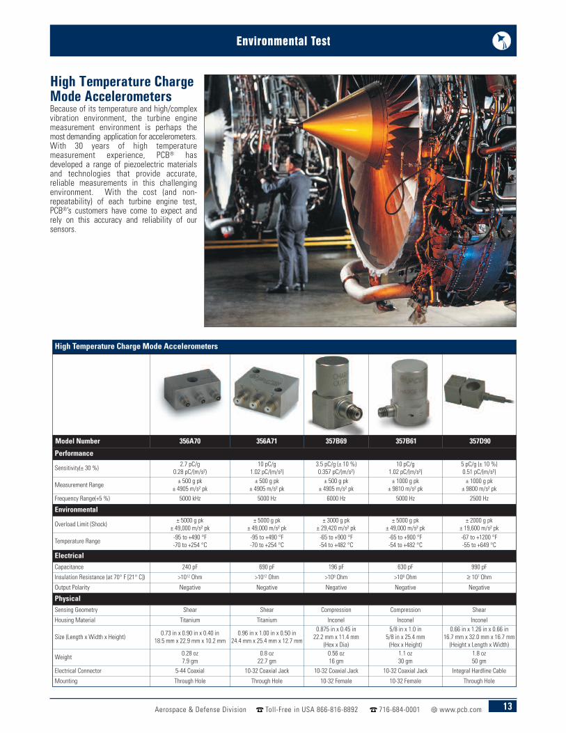
Model Number 356A70 356A71 357B69 357B61 357D90
Performance
Sensitivity(± 30 %) 2.7 pC/g0.28 pC/(m/s²)
10 pC/g1.02 pC/(m/s²)
3.5 pC/g (± 10 %)0.357 pC/(m/s²)
10 pC/g1.02 pC/(m/s²)
5 pC/g (± 10 %)0.51 pC/(m/s²)
Measurement Range ± 500 g pk± 4905 m/s² pk
± 500 g pk± 4905 m/s² pk
± 500 g pk± 4905 m/s² pk
± 1000 g pk± 9810 m/s² pk
± 1000 g pk± 9800 m/s² pk
Frequency Range(+5 %) 5000 kHz 5000 Hz 6000 Hz 5000 Hz 2500 Hz
Environmental
Overload Limit (Shock) ± 5000 g pk± 49,000 m/s² pk
± 5000 g pk± 49,000 m/s² pk
± 3000 g pk± 29,420 m/s² pk
± 5000 g pk± 49,000 m/s² pk
± 2000 g pk± 19,600 m/s² pk
Temperature Range -95 to +490 °F-70 to +254 °C
-95 to +490 °F-70 to +254 °C
-65 to +900 °F-54 to +482 °C
-65 to +900 °F-54 to +482 °C
-67 to +1200 °F-55 to +649 °C
ElectricalCapacitance 240 pF 690 pF 196 pF 630 pF 990 pF
Insulation Resistance (at 70° F [21° C]) >1012 Ohm >1012 Ohm >109 Ohm >108 Ohm ≥ 107 Ohm
Output Polarity Negative Negative Negative Negative Negative
PhysicalSensing Geometry Shear Shear Compression Compression Shear
Housing Material Titanium Titanium Inconel Inconel Inconel
Size (Length x Width x Height) 0.73 in x 0.90 in x 0.40 in18.5 mm x 22.9 mm x 10.2 mm
0.96 in x 1.00 in x 0.50 in24.4 mm x 25.4 mm x 12.7 mm
0.875 in x 0.45 in22.2 mm x 11.4 mm
(Hex x Dia)
5/8 in x 1.0 in5/8 in x 25.4 mm(Hex x Height)
0.66 in x 1.26 in x 0.66 in16.7 mm x 32.0 mm x 16.7 mm(Height x Length x Width)
Weight 0.28 oz7.9 gm
0.8 oz22.7 gm
0.56 oz16 gm
1.1 oz30 gm
1.8 oz50 gm
Electrical Connector 5-44 Coaxial 10-32 Coaxial Jack 10-32 Coaxial Jack 10-32 Coaxial Jack Integral Hardline Cable
Mounting Through Hole Through Hole 10-32 Female 10-32 Female Through Hole
High Temperature ChargeMode AccelerometersBecause of its temperature and high/complexvibration environment, the turbine enginemeasurement environment is perhaps themost demanding application for accelerometers.With 30 years of high temperaturemeasurement experience, PCB® hasdeveloped a range of piezoelectric materialsand technologies that provide accurate,reliable measurements in this challengingenvironment. With the cost (and non-repeatability) of each turbine engine test,PCB®’s customers have come to expect andrely on this accuracy and reliability of oursensors.
14 Aerospace & Defense Division Toll-Free in USA 866-816-8892 716-684-0001 www.pcb.com
Environmental Test
Cryogenic ICP® Accelerometers
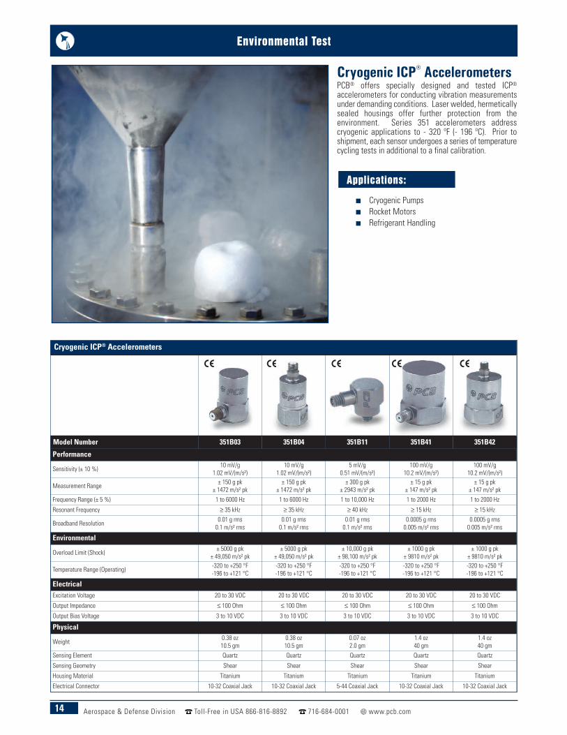
Model Number 351B03 351B04 351B11 351B41 351B42
Performance
Sensitivity (± 10 %) 10 mV/g1.02 mV/(m/s²)
10 mV/g1.02 mV/(m/s²)
5 mV/g0.51 mV/(m/s²)
100 mV/g10.2 mV/(m/s²)
100 mV/g10.2 mV/(m/s²)
Measurement Range ± 150 g pk± 1472 m/s² pk
± 150 g pk± 1472 m/s² pk
± 300 g pk± 2943 m/s² pk
± 15 g pk± 147 m/s² pk
± 15 g pk± 147 m/s² pk
Frequency Range (± 5 %) 1 to 6000 Hz 1 to 6000 Hz 1 to 10,000 Hz 1 to 2000 Hz 1 to 2000 Hz
Resonant Frequency ≥ 35 kHz ≥ 35 kHz ≥ 40 kHz ≥ 15 kHz ≥ 15 kHz
Broadband Resolution 0.01 g rms0.1 m/s² rms
0.01 g rms0.1 m/s² rms
0.01 g rms0.1 m/s² rms
0.0005 g rms0.005 m/s² rms
0.0005 g rms0.005 m/s² rms
Environmental
Overload Limit (Shock) ± 5000 g pk± 49,050 m/s² pk
± 5000 g pk± 49,050 m/s² pk
± 10,000 g pk± 98,100 m/s² pk
± 1000 g pk± 9810 m/s² pk
± 1000 g pk± 9810 m/s² pk
Temperature Range (Operating) -320 to +250 °F-196 to +121 °C
-320 to +250 °F-196 to +121 °C
-320 to +250 °F-196 to +121 °C
-320 to +250 °F-196 to +121 °C
-320 to +250 °F-196 to +121 °C
ElectricalExcitation Voltage 20 to 30 VDC 20 to 30 VDC 20 to 30 VDC 20 to 30 VDC 20 to 30 VDC
Output Impedance ≤ 100 Ohm ≤ 100 Ohm ≤ 100 Ohm ≤ 100 Ohm ≤ 100 OhmOutput Bias Voltage 3 to 10 VDC 3 to 10 VDC 3 to 10 VDC 3 to 10 VDC 3 to 10 VDC
Physical
Weight 0.38 oz10.5 gm
0.38 oz10.5 gm
0.07 oz2.0 gm
1.4 oz40 gm
1.4 oz40 gm
Sensing Element Quartz Quartz Quartz Quartz Quartz
Sensing Geometry Shear Shear Shear Shear Shear
Housing Material Titanium Titanium Titanium Titanium Titanium
Electrical Connector 10-32 Coaxial Jack 10-32 Coaxial Jack 5-44 Coaxial Jack 10-32 Coaxial Jack 10-32 Coaxial Jack
Cryogenic ICP® AccelerometersPCB® offers specially designed and tested ICP®accelerometers for conducting vibration measurementsunder demanding conditions. Laser welded, hermeticallysealed housings offer further protection from theenvironment. Series 351 accelerometers addresscryogenic applications to - 320 ºF (- 196 ºC). Prior toshipment, each sensor undergoes a series of temperaturecycling tests in additional to a final calibration.
Applications:
n Cryogenic Pumps n Rocket Motors n Refrigerant Handling
15Aerospace & Defense Division Toll-Free in USA 866-816-8892 716-684-0001 www.pcb.com
Environmental Test
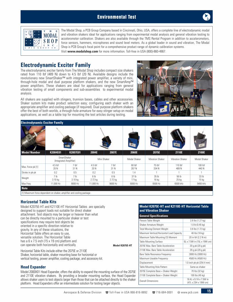
Electrodynamic Exciter FamilyThe electrodynamic exciter family from The Modal Shop includes compact size shakersrated from 110 lbf (489 N) down to 4.5 lbf (20 N). Available designs include therevolutionary new SmartShaker™ with integrated power amplifier, a variety of mini,through-hole modal and dual purpose platform shakers, and the new SmartAmp™power amplifiers. These shakers are ideal for applications ranging from generalvibration testing of small components and sub-assemblies to experimental modalanalysis.
All shakers are supplied with stingers, trunnion bases, cables and other accessories.Shaker system kits make product selection easy; configuring each shaker with anappropriate amplifier and cooling package (if required). Dual purpose platform shakersoffer the best of both worlds, a through-hole armature for easy stinger setup on modalapplications, as well as a table top for mounting the test articles during testing.
Horizontal Table KitsModel K2075E-HT and K2110E-HT Horizontal Tables are speciallydesigned to support loads not suitable for direct shakerattachment. Test objects may be larger or heavier than whatcan be directly mounted to a particular shaker or testspecifications may require test objects beoriented in a specific direction relative togravity. In any of these situations, theHorizontal Table offers an easy to use,versatile solution. The Horizontal Tablehas a 6 x 7.5 inch (15 x 19 cm) platform andcan operate both horizontally and vertically.
Horizontal Table Kits include either the 2075E or 2110EShaker, horizontal table, shaker mounting base for horizontal orvertical testing, power amplifier, cooling package, and accessory kit.
Head ExpanderModel 2000X01 Head Expander, offers the ability to expand the mounting surface of the 2075Eand 2110E vibration shakers. By providing a broader mounting surface, the Head Expanderallows shaker users to test objects larger than those that can be attached directly to the shakerplatform. Head Expanders offer an intermediate solution for testing larger objects.
Electrodynamic Exciter Family
Model Number K2004E01 K2007E01 2004E 2007E 2060E 2075E 2110E 2100E
SmartShaker(Integrated Amplifier) Mini Shaker Modal Shaker Vibration Shaker Vibration Shaker Modal Shaker
Max. Force pk [1] 4.5 lbf20 N
7 lbf31 N
4.5 lbf20 N
7 lbf31 N
60 lbf267 N
75 lbf334 N
110 lbf489 N
100 lbf440 N
Stroke in pk-pk 0.2 0.5 0.2 0.5 1.4 1 1 1
Weight 7 lb3.10 kg
7 lb3.10 kg
6 lb2.72 kg
6 lb2.72 kg
37 lb17 kg
35 lb16 kg
56 lb25 kg
33 lb15 kg
Max Freq 11,000 Hz 9000 Hz 11,000 Hz 9000 Hz 6000 Hz 6500 Hz 6500 kHz 5400 kHz
Note[1] Maximum force dependent on shaker, amplifier and cooling package
Model K2075E-HT and K2110E-HT Horizontal Tableand Vibration ShakerGeneral SpecificationsFlexure Table Weight 2.8 lbs (1.27 kg)
Shaker Armature Weight 1.0 lb (0.45 kg)
Total Moving Element Weight 3.8 lbs (1.72 kg)
Maximum Vertical/Horizontal Load Capacity 40 lbs (18 kg)
Maximum Table Mounting CG Moment 20 in lbf (2.2 N m)
Table Mounting Surface 6L x 7.5W in (15L x 19W cm)
2075E Max. Bare Table Acceleration 20 g pk (20 g pk)
2110E Max. Bare Table Acceleration 29 g pk (29 g pk)
Bare Table Resonance Frequency 3000 Hz (3000 Hz)
Maximum Useable Frequency 4500 Hz (4500 Hz)
Displacement 1.0 inch pk-pk (254.4 mm)
Table Mounting Hole Pattern Same as shaker
2075E Complete Base + Shaker Weight 70 lbs (32 kg)
2110E Complete Base + Shaker Weight 100 lbs (45 kg)
Overall Dimensions 18.4L x 9.1H x 7.5W in(47L x 23H x 19W cm)
The Modal Shop, a PCB Group Company based in Cincinnati, Ohio, USA, offers a complete line of electrodynamic modaland vibration shakers ideal for applications ranging from experimental modal analysis and general vibration testing toaccelerometer calibration. Shakers are also available through the TMS Rental Program in addition to accelerometers,force sensors, hammers, microphones and sound level meters. As a global leader in sound and vibration, The ModalShop is PCB Group’s focal point for a comprehensive product range of dynamic calibration systems. Visit www.modalshop.com for more information. Toll-free in USA (800)-860-4867.
Model K2075E-HT
16 Aerospace & Defense Division Toll-Free in USA 866-816-8892 716-684-0001 www.pcb.com
Environmental Test
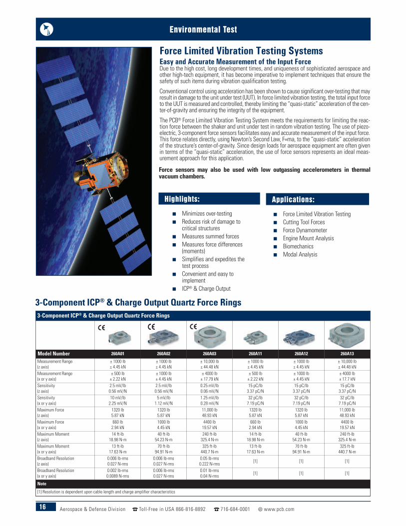
Highlights:
n Minimizes over-testingn Reduces risk of damage to
critical structuresn Measures summed forcesn Measures force differences
(moments)n Simplifies and expedites the
test processn Convenient and easy to
implementn ICP® & Charge Output
Easy and Accurate Measurement of the Input ForceDue to the high cost, long development times, and uniqueness of sophisticated aerospace andother high-tech equipment, it has become imperative to implement techniques that ensure thesafety of such items during vibration qualification testing.
Conventional control using acceleration has been shown to cause significant over-testing that mayresult in damage to the unit under test (UUT). In force limited vibration testing, the total input forceto the UUT is measured and controlled, thereby limiting the “quasi-static” acceleration of the cen-ter-of-gravity and ensuring the integrity of the equipment.
The PCB® Force Limited Vibration Testing System meets the requirements for limiting the reac-tion force between the shaker and unit under test in random vibration testing. The use of piezo-electric, 3-component force sensors facilitates easy and accurate measurement of the input force.This force relates directly, using Newton’s Second Law, F=ma, to the “quasi-static” accelerationof the structure’s center-of-gravity. Since design loads for aerospace equipment are often givenin terms of the “quasi-static” acceleration, the use of force sensors represents an ideal meas-urement approach for this application.
Force Limited Vibration Testing Systems
3-Component ICP® & Charge Output Quartz Force Rings
Model Number 260A01 260A02 260A03 260A11 260A12 260A13
Measurement Range(z axis)
± 1000 lb± 4.45 kN
± 1000 lb± 4.45 kN
± 10,000 lb± 44.48 kN
± 1000 lb± 4.45 kN
± 1000 lb± 4.45 kN
± 10,000 lb± 44.48 kN
Measurement Range(x or y axis)
± 500 lb± 2.22 kN
± 1000 lb± 4.45 kN
± 4000 lb± 17.79 kN
± 500 lb± 2.22 kN
± 1000 lb± 4.45 kN
± 4000 lb± 17.7 kN
Sensitivity(z axis)
2.5 mV/lb0.56 mV/N
2.5 mV/lb0.56 mV/N
0.25 mV/lb0.06 mV/N
15 pC/lb3.37 pC/N
15 pC/lb3.37 pC/N
15 pC/lb3.37 pC/N
Sensitivity(x or y axis)
10 mV/lb2.25 mV/N
5 mV/lb1.12 mV/N
1.25 mV/lb0.28 mV/N
32 pC/lb7.19 pC/N
32 pC/lb7.19 pC/N
32 pC/lb7.19 pC/N
Maximum Force(z axis)
1320 lb5.87 kN
1320 lb5.87 kN
11,000 lb48.93 kN
1320 lb5.87 kN
1320 lb5.87 kN
11,000 lb48.93 kN
Maximum Force(x or y axis)
660 lb2.94 kN
1000 lb4.45 kN
4400 lb19.57 kN
660 lb2.94 kN
1000 lb4.45 kN
4400 lb19.57 kN
Maximum Moment(z axis)
14 ft-lb18.98 N-m
40 ft-lb54.23 N-m
240 ft-lb325.4 N-m
14 ft-lb18.98 N-m
40 ft-lb54.23 N-m
240 ft-lb325.4 N-m
Maximum Moment(x or y axis)
13 ft-lb17.63 N-m
70 ft-lb94.91 N-m
325 ft-lb440.7 N-m
13 ft-lb17.63 N-m
70 ft-lb94.91 N-m
325 ft-lb440.7 N-m
Broadband Resolution(z axis)
0.006 lb-rms0.027 N-rms
0.006 lb-rms0.027 N-rms
0.05 lb-rms0.222 N-rms [1] [1] [1]
Broadband Resolution(x or y axis)
0.002 lb-rms0.0089 N-rms
0.006 lb-rms0.027 N-rms
0.01 lb-rms0.04 N-rms [1] [1] [1]
Note
[1] Resolution is dependent upon cable length and charge amplifier characteristics
Applications:
n Force Limited Vibration Testingn Cutting Tool Forcesn Force Dynamometern Engine Mount Analysisn Biomechanicsn Modal Analysis
3-Component ICP® & Charge Output Quartz Force Rings
Force sensors may also be used with low outgassing accelerometers in thermalvacuum chambers.

17Aerospace & Defense Division Toll-Free in USA 866-816-8892 716-684-0001 www.pcb.com
Environmental Test
3-Component ICP® & Charge Output Quartz Force Links3-Component ICP® & Charge Output Quartz Force Links
Model Number 261A01 261A02 261A03 261A11 261A12 261A13
Measurement Range(z axis)
± 1000 lb± 4.45 kN
± 1000 lb± 4.45 kN
± 10,000 lb± 44.48 kN
± 1000 lb± 4.45 kN
± 1000 lb± 4.45 kN
± 10,000 lb± 44.48 kN
Measurement Range(x or y axis)
± 500 lb± 2.22 kN
± 1000 lb± 4.45 kN
± 4000 lb± 17.79 kN
± 500 lb± 2.22 kN
± 1000 lb± 4.45 kN
± 4000 lb± 17.7 kN
Sensitivity(z axis)
2.5 mV/lb0.56 mV/N
2.5 mV/lb0.56 mV/N
0.25 mV/lb0.06 mV/N
15 pC/lb3.37 pC/N
15 pC/lb3.37 pC/N
15 pC/lb3.37 pC/N
Sensitivity(x or y axis)
10 mV/lb2.25 mV/N
5 mV/lb1.12 mV/N
1.25 mV/lb0.28 mV/N
32 pC/lb7.19 pC/N
32 pC/lb7.19 pC/N
32 pC/lb7.19 pC/N
Maximum Force(z axis)
1320 lb5.87 kN
1320 lb5.87 kN
11,000 lb48.93 kN
1320 lb5.87 kN
1320 lb5.87 kN
11,000 lb48.93 kN
Maximum Force(x or y axis)
660 lb2.94 kN
1000 lb4.45 kN
4400 lb19.57 kN
660 lb2.94 kN
1000 lb4.45 kN
4400 lb19.57 kN
Maximum Moment(z axis)
14 ft-lb18.98 N-m
40 ft-lb54.23 N-m
240 ft-lb325.4 N-m
14 ft-lb18.98 N-m
40 ft-lb54.23 N-m
240 ft-lb325.4 N-m
Maximum Moment(x or y axis)
13 ft-lb17.63 N-m
70 ft-lb94.91 N-m
325 ft-lb440.7 N-m
13 ft-lb17.63 N-m
70 ft-lb94.91 N-m
325 ft-lb440.7 N-m
Broadband Resolution(z axis)
0.006 lb-rms0.027 N-rms
0.006 lb-rms0.027 N-rms
0.05 lb-rms0.222 N-rms [1] [1] [1]
Broadband Resolution(x or y axis)
0.002 lb-rms0.0089 N-rms
0.006 lb-rms0.027 N-rms
0.01 lb-rms0.04 N-rms [1] [1] [1]
Note
[1] Resolution is dependent upon cable length and charge amplifier characteristics
Model 443B102 Dual-Mode Amplifier ModuleChannels 1
Display (Menu Driven) Backlit 2 × 16 character LCD
Voltage Gain (ICP® Sensor Mode) ×0.1 to ×1000 (4-digit resolution)
Charge Gain (Charge Mode) 0.1 to 10 000 mV/pC (4-digit resolution)
Discharge Time Constant 0.18, 1.8, 10, 100, 1000, > 100k sec
Drift [1] < 0.03 pC/secBroadband Noise (ICP® Sensor Mode) [2](2 Hz to 22.4 kHz) < 3 µV (< -110.5 dB)
Broadband Noise (Charge Mode) [3](2 Hz to 22.4 kHz) < 5 fC (< 0.005 pC)
Low Frequency Response (-10%) 2, 0.2, 0.03, 0.003, 0.0003 ~0 Hz
High Frequency Response (-10%) 0.1,1, 3, 10, 100, >200 kHz
Model 070A15 Summing BlockInput 4-Channels of Charge Input
Output 1-Channel of Summed Charge Output
Model 070M70 Charge Summation Node ModuleInput 8-Channels of charge mode sensor signals
Summed Output (Charge Mode) 1-Channel (A + B + C + D + E + F + G + H)
Signal Conditioning System Component SpecificationsModel 070M69 Computational Signal ConditionerInput 8-Channels of ICP® sensor or voltage signals
Computational Function [(A-B) + (C-D) + (E-F) + (G-H)] × Gain
Excitation Voltage (for ICP® Sensors) 24 VDC
Excitation Current (Selectable) 0, 2, 4, 8, 12, 20 mA
Differenced Output 4-Channels: (A-B), (C-D), (E-F), (G-H)
Function Output 1-Channel
Gain ×0.1, ×1, ×10
Model 070M90 12-Channel Summing AmplifierInput 12-Channels of ICP® signals
Excitation Voltage (for ICP® Sensors) 24 VDC
Excitation Current 2 to 20 mA adjustable
Output 1-Channel
Gain x0.1, x1, x10
Notes:
[1] Long discharge time constant mode.[2] Measured at gain of 1000 (60 dB), input referred.[3] Measured at gain of 10 V/pC (80 dB) with a 1 nF source capacitance, input referred.
Model 443B102Dual-Mode Amplifier Module
Model 070M69Computational Signal
Conditioner
Model 070M90Summing Amplifierfor ICP® Sensors
Combined SystemModel 070A15
Summing Block forCharge Mode Sensors
Model 070M70Charge SummationNode Module
18 Aerospace & Defense Division Toll-Free in USA 866-816-8892 716-684-0001 www.pcb.com
Environmental Test
Water Cooled, Helium Bleed Pressure SensorsModel Number 123A 123A21 123A22 123A23 123A24
Performance
Sensitivity (± 15 %) 1.0 pC/psi0.145 mV/kPa
20 mV/psi2.90 mV/kPa
1.0 mV/psi0.145 mV/kPa
0.5 mV/psi0.07 mV/kPa
5.0 mV/psi0.725 mV/kPa
Measurement Range 3 kpsi20,685 kPa
250 psi1724 kPa (for ±5V output)
3 kpsi20,685 kPa (for ± 3V output)
10 kpsi68,950 kPa
1 kpsi6895, kPa (for ±5V output)
Maximum Pressure 5 kpsi34,475 kPa
5 kpsi34,475 kPa
5 kpsi34,475 kPa
20 kpsi137,900 kPa
5 kpsi34,475 kPa
Environmental
Acceleration Sensitivity ≤ 0.002 psi/g≤0.0014 kPa/(m/s²)
≤ 0.002 psi/g≤0.0014 kPa/(m/s²)
≤ 0.002 psi/g≤ 0.0014 kPa/(m/s²)
≤ 0.002 psi/g≤ 0.0014 kPa/(m/s²)
≤ 0.002 psi/g≤ 0.0014 kPa/(m/s²)
Temperature Range (Operating) [1] -450 to +500 °F-73 to +121 °C
-100 to +250 °F-73 to +121 °C
-100 to +250 °F-73 to +121 °C
-100 to +250 °F-73 to +121 °C
-100 to +250 °F-73 to +121 °C
Maximum Shock 10,000 g pk98,070 m/s² pk
10,000 g pk98,070 m/s² pk
10,000 g pk98,070 m/s² pk
10,000 g pk98,070 m/s² pk
10,000 g pk98,070 m/s² pk
ElectricalOutput Polarity (Positive Pressure) Negative Positive Positive Positive Positive
PhysicalHousing Material 17-4 Stainless Steel 17-4 Stainless Steel 17-4 Stainless Steel 17-4 Stainless Steel 17-4 Stainless Steel
Diaphragm Invar Invar Invar Invar Invar
Electrical Connector Integral Cable Integral Cable Integral Cable Integral Cable Integral Cable
Cable Length 4 ft1.2 m
4 ft1.2 m
4 ft1.2 m
4 ft1.2 m
4 ft1.2 m
Weight 4.23 oz120 gm
4.23 oz120 gm
4.23 oz120 gm
4.23 oz120 gm
4.23 oz120 gm
Note[1] When maintained with water cooling flow and helium bleed per factory specification.
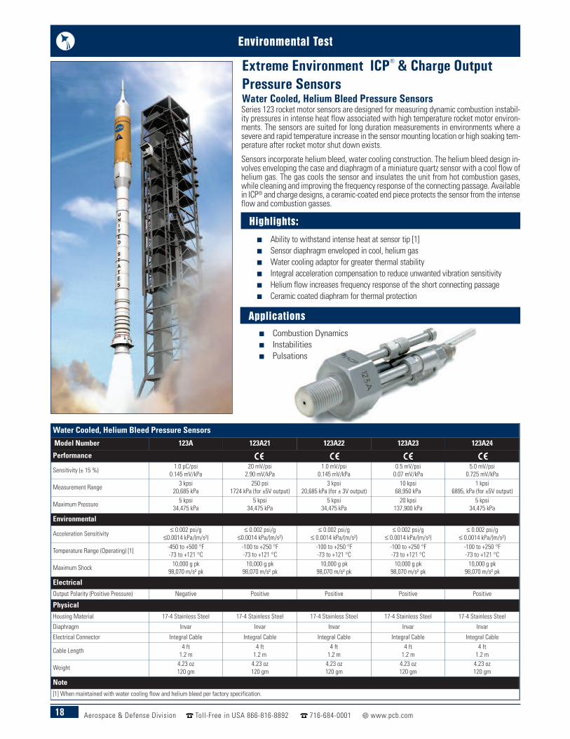
Series 123 rocket motor sensors are designed for measuring dynamic combustion instabil-ity pressures in intense heat flow associated with high temperature rocket motor environ-ments. The sensors are suited for long duration measurements in environments where asevere and rapid temperature increase in the sensor mounting location or high soaking tem-perature after rocket motor shut down exists.
Sensors incorporate helium bleed, water cooling construction. The helium bleed design in-volves enveloping the case and diaphragm of a miniature quartz sensor with a cool flow ofhelium gas. The gas cools the sensor and insulates the unit from hot combustion gases,while cleaning and improving the frequency response of the connecting passage. Availablein ICP® and charge designs, a ceramic-coated end piece protects the sensor from the intenseflow and combustion gasses.
Extreme Environment ICP® & Charge Output Pressure SensorsWater Cooled, Helium Bleed Pressure Sensors
Applicationsn Combustion Dynamicsn Instabilitiesn Pulsations
n Ability to withstand intense heat at sensor tip [1]n Sensor diaphragm enveloped in cool, helium gasn Water cooling adaptor for greater thermal stability n Integral acceleration compensation to reduce unwanted vibration sensitivityn Helium flow increases frequency response of the short connecting passagen Ceramic coated diaphram for thermal protection
Highlights:

19Aerospace & Defense Division Toll-Free in USA 866-816-8892 716-684-0001 www.pcb.com
Environmental Test
High Temperature Cryogenic
Model Number 112A05 116B 176M03 102A10 102A14
Performance
Sensitivity (± 15 %) 1.1 pC/psi0.160 pC/kPa (-10 to +25 %)
6 pC/psi0.870 pC/kPa
17 pC/psi2.47 pC/kPa (± 20 %)
50 mV/psi7.25 mV/kPa
1.0 mV/psi0.145 mV/kPa
Measurement Range 5,000 psi34,475 kPa
100 psi690 kPa
20 psi137.9 kPa
100 psi690 kPa
5,000 psi34,475 kPa
Maximum Pressure (static) 10,000 psi68,950 kPa
3,000 psi20,685 kPa
400 psi2758 kPa
15,000 psi103,425 kPa
15,000 psi103,425 kPa
Resonant Frequency ≥ 200 kHz ≥ 55 kHz >50 kHz ≥ 250 kHz ≥ 250 kHz
Environmental
Acceleration Sensitivity ≤ 0.003 psi/g≤0.0021 kPa/(m/s²)
≤ .002 psi/g≤.0014 kPa/(m/s²)
≤ 0.01 psi/g≤ 0.007 kPa/(m/s²)
≤ 0.002 psi/g≤0.0014 kPa/(m/s²)
≤ 0.002 psi/g≤0.0014 kPa/(m/s²)
Temperature Range (Operating) -400 to +600 °F-240 to +316 °C
-400 to 650 °F-240 to 345 °C
986 °F530 °C
-320 to +212 °F-196 to +100 °C
-320 to +212 °F-196 to +100 °C
PhysicalHousing Material 17-4 Stainless Steel 316L Stainless Steel Inconel Stainless Steel Stainless Steel
Electrical Connector 10-32 Coaxial Jack 10-32 Coaxial Jack 2-Pin 10-32 Coaxial Jack 10-32 Coaxial Jack
Weight 0.212 oz6.0 gm
0.717 oz20.3 gm
4.9 oz140 gm
0.388 oz11.00 gm
0.388 oz11.00 gm
Model 064B06Product Type: Accessory, Thread AdaptorWater-cooled adaptor, sensor recess mount, M20 x 1.5 External thd,1.25" hex (for Model 116B) Other versions are available
ATEX
Highlights:
n Laser welded, hermetically sealed quartz sensingelements
n Fused ceramic insulation connectorsn Internal acceleration compensation
minimizes vibration sensitivityn Calibration supplied at room temperature with
thermal coefficients up to +750 °F (+399 °C)
Highlights:
n Fast rise time of ≤ 2 μsec from quartz element, with highresonant frequency ≥ 250 kHz
n Welded, hermetically sealed, stainless steel construction n Electrically ground isolated, which helps prevent ground
loop challengesn Calibration supplied at room temperature with thermal
coefficients down to -320 °F (-196 °C)
PCB® High Temperature Charge Ouput SensorsPCB® High Temperature quartz dynamic pressure sensors are designed foroperation at the highest temperatures. They are structured with quartzcrystals and operate, without cooling, up to +750 °F (+399 °C) on com-pressors and pumps. Special mounting adaptors can be supplied to fitexisting mounting holes. Water cooled adaptors are available to providea lower temperature thermally stable environment that allow sensors tooperate in applications above their normal operating range.
Hard-line cables are recommended for operating temperatures above+500 °F (+260 °C). The cable can be welded to the sensor for operation inpressurized environments. All of these features ensure reliable operationin high temperature environments.
PCB® Cryogenic ICP® Pressure Sensors PCB® Cryogenic quartz dynamic pressure sensors are a high resolutionICP® pressure sensor design, specially made for cryogenic environments.They consistently follow dynamic events found in cryogenic turbo pumpsfor liquid fuel handling systems or biomedical research.
Model 064B01Product Type: Accessory, Thread AdaptorWater-cooled adaptor, sensor recess mount, 1/2-20External thd, 1.0" hex (for Model 112A05)
20 Aerospace & Defense Division Toll-Free in USA 866-816-8892 716-684-0001 www.pcb.com
Environmental Test
Underwater High Intensity Acoustic ICP® Pressure Sensors
Model Number 103B01 106B 112A22 113B28
Performance
Measurement Range(± 5 V output) 3.33 psi181 dB
8.3 psi57.2 kPa (for ±2.5V output)
50 psi345 kPa
50 psi345 kPa
Sensitivity(± 15 %) 1500 mV/psi217.5 mV/kPa
300 mV/psi43.5 mV/kPa
100 mV/psi14.5 mV/kPa
100 mV/psi14.5 mV/kPa
Maximum Pressure 250 psi1725 kPa
200 psi1379 kPa
500 psi3450 kPa
1,000 psi690 kPa
Resonant Frequency ≥ 13 kHz ≥ 60 kHz ≥ 250 kHz ≥ 500 kHzRise Time ≤ 25 µ sec ≤ 9 µ sec ≤ 2.0 µ sec ≤ 1.0 µ secLow Frequency Response(-5 %) 5 Hz 0.5 Hz 0.5 Hz 0.5 Hz
Environmental
Acceleration Sensitivity ≤ 0.0005 psi/g≤0.0035 psi/(m/s2)
≤ 0.002 psi/g≤0.0014 psi/(m/s2)
≤ 0.002 psi/g≤0.0014 psi/(m/s2)
≤ 0.002 psi/g≤0.0014 psi/(m/s2)
Temperature Range (Operating) -100 to 250 °F-73 to +121°C
-65 to +250 °F-54 to +121°C
-100 to +275 °F-73 to +135°C
-100 to +275 °F-73 to +135°C
Maximum Shock 1000 g pk 2000 g pk 20,000 g pk 20,000 g pk
ElectricalOutput Polarity (Positive Pressure) Positive Positive Positive Positive
Excitation Voltage 20 to 30 VDC 12 to 30 VDC 22 to 30 VDC 22 to 30 VDC
Output Impedance ≤ 100 Ohm ≤ 100 Ohm < 100 Ohm < 100 Ohm
PhysicalSensing Element Ceramic Quartz Quartz Quartz
Diaphragm 316L Stainless Steel 316L Stainless Steel Invar Invar
Electrical Connector Integral Cable 10-32 Coaxial Jack 10-32 Coaxial Jack 10-32 Coaxial Jack
Weight 0.115 oz3.260 gm
0.63 oz18.0 gm
0.21 oz6.0 gm
0.16 oz4.5 gm
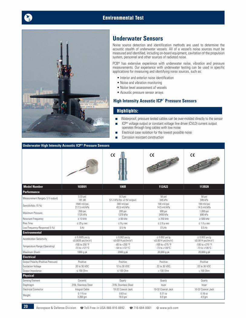
Underwater SensorsNoise source detection and identification methods are used to determine theacoustic stealth of underwater vessels. All of a vessel’s noise sources must bemeasured and identified, including on-board equipment, cavitation of the propulsionsystem, personnel and other sources of radiated noise.
PCB® has extensive experience with underwater noise, vibration and pressuremeasurements. Our experience with underwater testing can be used in specificapplications for measuring and identifying noise sources, such as:
• Interior and exterior noise identification • Noise and vibration monitoring• Noise level assessment of vessels• Acoustic pressure sensor arrays
n Waterproof, pressure tested cables can be over-molded directly to the sensorn ICP® voltage output or constant voltage line driver (CVLD) current output
operates through long cables with low noisen Electrical case isolation for the lowest possible noisen Corrosion resistant construction
Highlights:
High Intensity Acoustic ICP® Pressure Sensors
21Aerospace & Defense Division Toll-Free in USA 866-816-8892 716-684-0001 www.pcb.com
Environmental Test
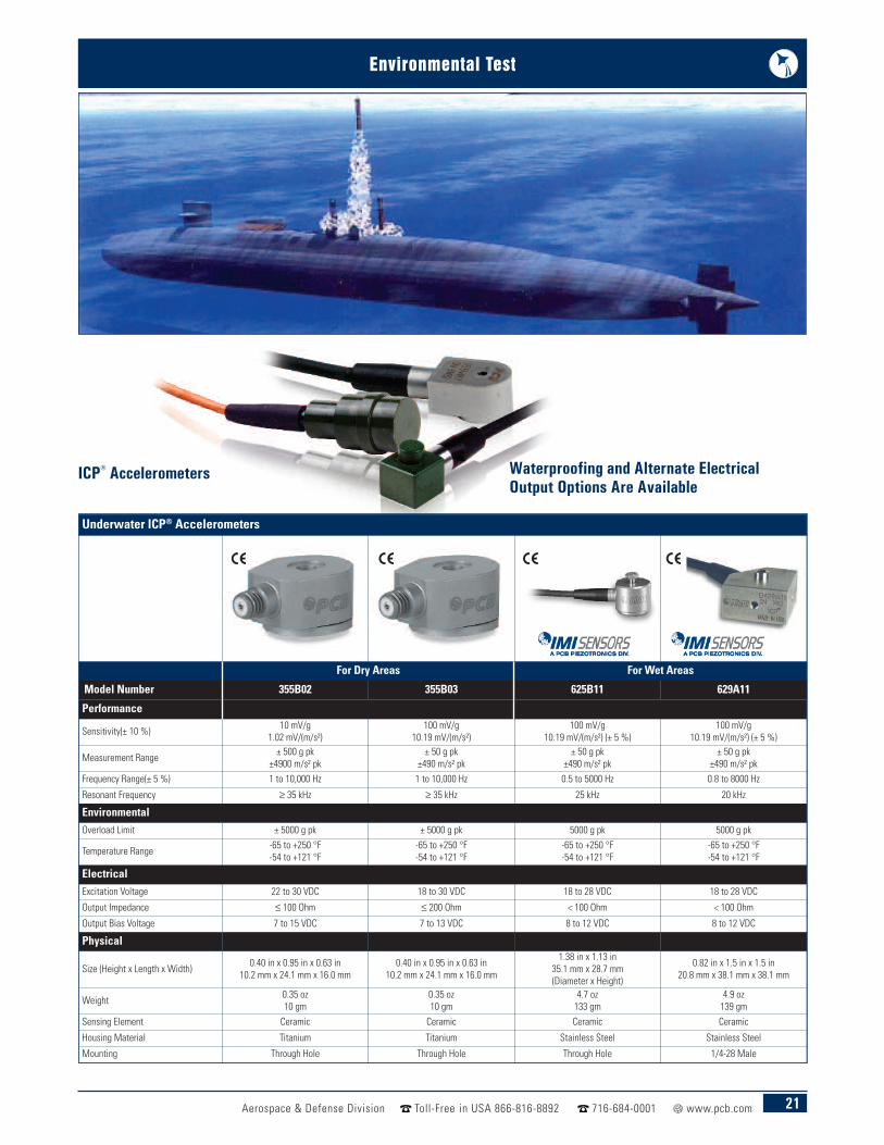
Waterproofing and Alternate ElectricalOutput Options Are Available
Underwater ICP® Accelerometers
For Dry Areas For Wet Areas
Model Number 355B02 355B03 625B11 629A11
Performance
Sensitivity(± 10 %) 10 mV/g1.02 mV/(m/s²)
100 mV/g10.19 mV/(m/s²)
100 mV/g10.19 mV/(m/s²) (± 5 %)
100 mV/g10.19 mV/(m/s²) (± 5 %)
Measurement Range ± 500 g pk±4900 m/s² pk
± 50 g pk±490 m/s² pk
± 50 g pk±490 m/s² pk
± 50 g pk±490 m/s² pk
Frequency Range(± 5 %) 1 to 10,000 Hz 1 to 10,000 Hz 0.5 to 5000 Hz 0.8 to 8000 Hz
Resonant Frequency ≥ 35 kHz ≥ 35 kHz 25 kHz 20 kHz
EnvironmentalOverload Limit ± 5000 g pk ± 5000 g pk 5000 g pk 5000 g pk
Temperature Range -65 to +250 °F-54 to +121 °F
-65 to +250 °F-54 to +121 °F
-65 to +250 °F-54 to +121 °F
-65 to +250 °F-54 to +121 °F
ElectricalExcitation Voltage 22 to 30 VDC 18 to 30 VDC 18 to 28 VDC 18 to 28 VDC
Output Impedance ≤ 100 Ohm ≤ 200 Ohm < 100 Ohm < 100 Ohm
Output Bias Voltage 7 to 15 VDC 7 to 13 VDC 8 to 12 VDC 8 to 12 VDC
Physical
Size (Height x Length x Width) 0.40 in x 0.95 in x 0.63 in10.2 mm x 24.1 mm x 16.0 mm
0.40 in x 0.95 in x 0.63 in10.2 mm x 24.1 mm x 16.0 mm
1.38 in x 1.13 in35.1 mm x 28.7 mm(Diameter x Height)
0.82 in x 1.5 in x 1.5 in20.8 mm x 38.1 mm x 38.1 mm
Weight 0.35 oz10 gm
0.35 oz10 gm
4.7 oz133 gm
4.9 oz139 gm
Sensing Element Ceramic Ceramic Ceramic Ceramic
Housing Material Titanium Titanium Stainless Steel Stainless Steel
Mounting Through Hole Through Hole Through Hole 1/4-28 Male
ICP® Accelerometers
22 Aerospace & Defense Division Toll-Free in USA 866-816-8892 716-684-0001 www.pcb.com
Environmental Test
Highlights:
n DC to ≤ 1 msec response timen Stainless steel wetted partsn All welded construction with no adhesives,
seals, or fluid filling n Gage, sealed gage, absolute, or compound
pressure versions
n 4-Digit indicator with sensor powersupply
n Provides 24 VDC excitation for voltageoutput pressure transducers or currentoutput pressure transmitters
n High visibility, 4-digit, fully scalable, LEDdisplay
n Straight forward, menu-driven set-upn Optional user-programmable set points
with relays and LED alarm statusindicators
n Optional 4-20 mA output for processrecorder or PLC
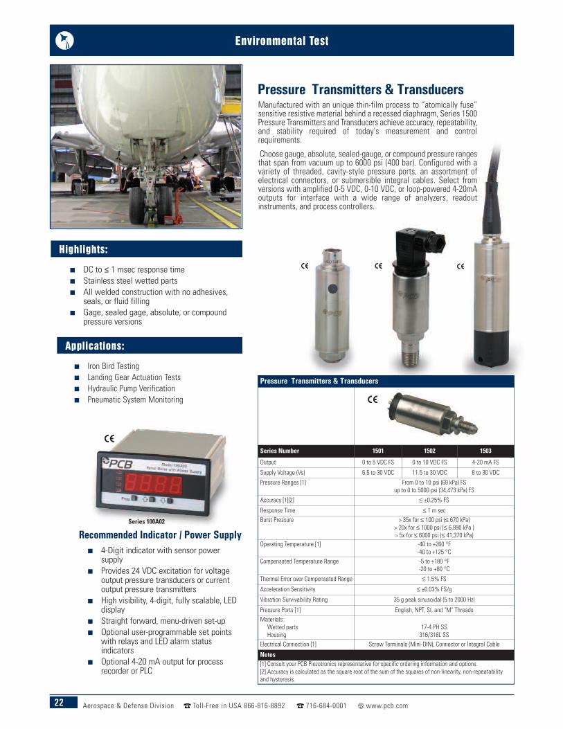
Manufactured with an unique thin-film process to “atomically fuse”sensitive resistive material behind a recessed diaphragm, Series 1500Pressure Transmitters and Transducers achieve accuracy, repeatability,and stability required of today's measurement and controlrequirements.
Choose gauge, absolute, sealed-gauge, or compound pressure rangesthat span from vacuum up to 6000 psi (400 bar). Configured with avariety of threaded, cavity-style pressure ports, an assortment ofelectrical connectors, or submersible integral cables. Select fromversions with amplified 0-5 VDC, 0-10 VDC, or loop-powered 4-20mAoutputs for interface with a wide range of analyzers, readoutinstruments, and process controllers.
Recommended Indicator / Power Supply
Pressure Transmitters & Transducers
Pressure Transmitters & Transducers
Series Number 1501 1502 1503
Output 0 to 5 VDC FS 0 to 10 VDC FS 4-20 mA FS
Supply Voltage (Vs) 6.5 to 30 VDC 11.5 to 30 VDC 8 to 30 VDC
Pressure Ranges [1] From 0 to 10 psi (69 kPa) FS up to 0 to 5000 psi (34,473 kPa) FS
Accuracy [1][2] ≤ ±0.25% FS
Response Time ≤ 1 m secBurst Pressure > 35x for ≤ 100 psi (≤ 670 kPa)
> 20x for ≤ 1000 psi (≤ 6,890 kPa )> 5x for ≤ 6000 psi (≤ 41,370 kPa)
Operating Temperature [1] -40 to +260 °F-40 to +125 °C
Compensated Temperature Range -5 to +180 °F-20 to +80 °C
Thermal Error over Compensated Range ≤ 1.5% FS
Acceleration Sensitivity ≤ ±0.03% FS/g
Vibration Survivability Rating 35 g peak sinusoidal (5 to 2000 Hz)
Pressure Ports [1] English, NPT, SI, and "M" ThreadsMaterials:
Wetted partsHousing
17-4 PH SS316/316L SS
Electrical Connection [1] Screw Terminals (Mini-DIN), Connector or Integral Cable
Notes[1] Consult your PCB Piezotronics representative for specific ordering information and options.[2] Accuracy is calculated as the square root of the sum of the squares of non-linearity, non-repeatabilityand hysteresis.
Series 100A02
Applications:
n Iron Bird Testing n Landing Gear Actuation Tests n Hydraulic Pump Verification n Pneumatic System Monitoring
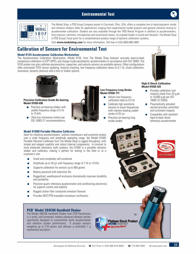
Model 9155 Accelerometer Calibration Workstation The Accelerometer Calibration Workstation, Model 9155, from The Modal Shop features accurate back-to-backcomparison calibration of ICP® (IEPE), and charge mode piezoelectric accelerometers in accordance with ISO 16063. The9155 system can also calibrate piezoresistive, capacitive, and velocity sensors via available options. Other configurationsoffer automated TEDS sensor updating, linearity checking, low frequency calibration down to 0.1 Hz, shock calibration,resonance, dynamic pressure and a host of shaker options.
Calibration of Sensors for Environmental Test
PCB® Model 394C06 Handheld ShakerThe Model 394C06 Handheld Shaker from PCB Piezotronicsis a small, self-contained, battery powered vibration exciterspecifically designed to conveniently verify accelerometerand vibration system performance. It accepts sensorsweighing up to 210 grams and delivers a controlled 1 gmechanical excitation.
n Small and completely self-containedn Amplitude up to 20 g’s with frequency range of 7 Hz to 10 kHzn Supports calibration for sensors up to 800 gramsn Battery powered with extensive lifen Ruggedized, weatherproof enclosure dramatically improves durability
and portabilityn Precision quartz reference accelerometer and conditioning electronics
for superior control and stabilityn Rugged carbon fiber composite armature flexuresn Provides NIST/PTB traceable transducer verification
Model 9100D Portable Vibration CalibratorIdeal for checking accelerometers, velocity transducers and proximity probesover a wide frequency and amplitude operating range, the Model 9100DPortable Vibration Calibrator from The Modal Shop is rugged throughout, withsimple and elegant usability and robust internal components. In contrast tomore elaborate laboratory style systems, the 9100D is a portable vibrationshaker and calibrator, making it perfect for testing in the field or at acustomer's site.
High-G Shock CalibrationModel 9155D-525
n Provides calibration andlinearity check from 20 g-pkto 10,000 g-pk per ISO16062-22 (2005).
n Pneumatically actuatedexcited provides controlledand consistent impacts
n Compatible with standardback-to-back shockreference accelerometer
Low Frequency Long StrokeModel 9155D-771
n Allows low frequencycalibration data to 0.5 Hz
n Calibrate high sensitivitysensors to lower frequencieswith industry leading usablestroke of 25 cm
n Precision air-bearing longstroke shaker
Precision Calibration Grade Air-bearingModel 9155D-830
n Precision air-bearing shaker withusable frequency range of 5 Hzto 15 kHz
n Ultra-low transverse motion perISO 16063-21 recommendations
23Aerospace & Defense Division Toll-Free in USA 866-816-8892 716-684-0001 www.pcb.com
Environmental Test
The Modal Shop, a PCB Group Company based in Cincinnati, Ohio, USA, offers a complete line of electrodynamic modaland vibration shakers ideal for applications ranging from experimental modal analysis and general vibration testing toaccelerometer calibration. Shakers are also available through the TMS Rental Program in addition to accelerometers,force sensors, hammers, microphones and sound level meters. As a global leader in sound and vibration, The Modal Shopis PCB Group’s focal point for a comprehensive product range of dynamic calibration systems. Visit www.modalshop.com for more information. Toll-free in USA (800)-860-4867.

24 Aerospace & Defense Division Toll-Free in USA 866-816-8892 716-684-0001 www.pcb.com
Environmental Test
Flange-shaft Rotary Transformer Torque Sensors
Model Number 4115K-04A 4115K-06A 4115K-08A 4115K-11A 4115K-13A
Performance
Measurement Range (Full Scale Capacity) 500 in-lb55 Nm
1000 in-lb115 Nm
2000 in-lb225 Nm
5000 in-lb565 Nm
10,000 in-lb1,130 Nm
Sensitivity(±15%) (output at rated capacity) 2.5 mV/V 2.5 mV/V 2.5 mV/V 2.5 mV/V 2.5 mV/V
Hysteresis ≤ 0.05 % FS ≤ 0.05 % FS ≤ 0.05 % FS ≤ 0.05 % FS ≤ 0.05 % FS
Environmental
Overload Limit 1500 in-lb170 Nm
3000 in-lb340 Nm
6000 in-lb675 Nm
15,000 in-lb1700 Nm
15,000 in-lb1700 Nm
Temperature Range (Operating) -65 to +285 °F-54 to 141 °C
-65 to +285 °F-54 to 141 °C
-65 to +285 °F-54 to 141 °C
-65 to 225 °F-54 to 107 °C
-65 to 225 °F-54 to 107 °C
ElectricalBridge Resistance 350 Ohm 350 Ohm 350 Ohm 350 Ohm 350 Ohm
Excitation Frequency 3,280 Hz 3,280 Hz 3,280 Hz 3,280 Hz 3,280 Hz
Bridge Current (at 5 VAC) 50 mA 50 mA 50 mA 50 mA 50 mA
Physical
Size (Shaft Length x Housing Length xHousing Height)
9.56 in x 8.25 in x 6.00 in242.82 mm x 209.55 mm x
152.40 mm
9.56 in x 8.25 in x 6.00 in242.82 mm x 209.55 mm x
152.40 mm
9.56 in x 8.25 in x 6.00 in242.82 mm x 209.55 mm x
152.40 mm
9.56 in x 8.25 in x 6.00 in242.82 mm x 209.55 mm x
152.40 mm
9.56 in x 8.25 in x 6.00 in242.82 mm x 209.55 mm x
152.40 mm
Weight 47 lb21.3 Kg
47 lb21.3 Kg
47 lb21.3 Kg
47 lb21.3 Kg
47 lb21.3 Kg
Mounting Flange w/ Splined Shaft Flange w/ Splined Shaft Flange w/ Splined Shaft Flange w/ Splined Shaft Flange w/ Splined Shaft
Sensing Element Strain Gage Strain Gage Strain Gage Strain Gage Strain Gage
Shaft Material Steel Steel Steel Steel Steel
Electrical Connector MS3102A-14S-5P MS3102A-14S-5P MS3102A-14S-5P MS3102A-14S-5P MS3102A-14S-5P
Maximum Speed 15,000 RPM 15,000 RPM 15,000 RPM 15,000 RPM 15,000 RPM
PCB Load & Torque, Inc. Torque Sensors
Highlights:
n Capacities from 50 to 10k in-lbFS (5.6 to 1130 Nm FS)
n 2.5 mV/V output sensitivity n Splined shaft drive n High signal-to-noise ratio n High torsional stiffness
Flange-shaft Rotary Transformer Torque SensorsAerospace hydraulic pumps and motors require an end-of-line production test for torque to ensure flight worthiness prior to installation on aircraft. Thesepumps are responsible for providing highly reliable hydraulic pressure required for control surface and landing gear actuation. Other common applicationsinclude landing gear retraction system torque, ball screw and gearbox torque for wing flaps and leading edge slat actuation testing, aircraft starter testing,cross-bleed system testing, and high speed fuel pump testing. For example, gearboxes and their output drives used in flap actuation or landing gearretraction must meet stringent life cycle and wear requirements. Such gearboxes have to be 100% tested end-of-line for specific load profiles to simulaterealistic control surface actuation.PCB Load & Torque, Inc. Series 4115K Rotary Torque Transducers use non-contact rotary transformer technology for sending excitation to and receivingmeasurement signals from a strain gage instrumented rotating shaft. Their unique flange and splined shaft design, which conforms to AND 10262 &20002 standards, mate directly to aerospace industry standard hydraulic pumps and accessories. These units feature high torsional stiffness and lowrotating inertia. Models are available with several measurement ranges and standard operating speeds up to 15,000 rpm.To enable reliability assessment the input torque is measured as a function of speed. So, in addition to the torque output signal, optional speed sensorsprovide an output proportional to rotational speed. Optional K-type thermocouples monitor internal bearing temperature.
Shown with OptionalSpeed Sensor Installed
PCB Load & Torque, Inc., a wholly-owned subsidary of PCB Piezotronics, is a manufacturer of highquality, precision load cells, torque transducers, and telemetry units. In addition to the qualityproducts produced, PCB Load & Torque’s custmer support services mirror those of PCB Piezotronics.Visit www.pcbloadtorque.com for more information. Toll-free in USA (866)-684-7107.
25Aerospace & Defense Division Toll-Free in USA 866-816-8892 716-684-0001 www.pcb.com
Environmental Test
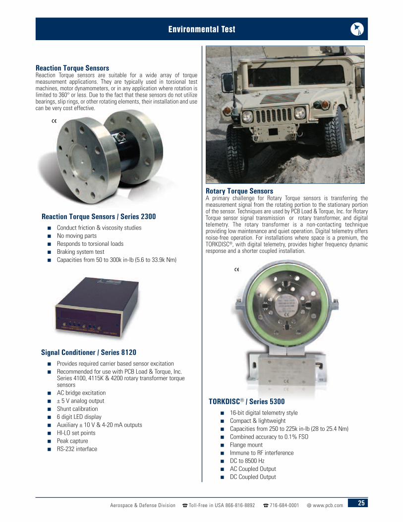
Rotary Torque SensorsA primary challenge for Rotary Torque sensors is transferring themeasurement signal from the rotating portion to the stationary portionof the sensor. Techniques are used by PCB Load & Torque, Inc. for RotaryTorque sensor signal transmission or rotary transformer, and digitaltelemetry. The rotary transformer is a non-contacting techniqueproviding low maintenance and quiet operation. Digital telemetry offersnoise-free operation. For installations where space is a premium, theTORKDISC®, with digital telemetry, provides higher frequency dynamicresponse and a shorter coupled installation.
Reaction Torque SensorsReaction Torque sensors are suitable for a wide array of torquemeasurement applications. They are typically used in torsional testmachines, motor dynamometers, or in any application where rotation islimited to 360° or less. Due to the fact that these sensors do not utilizebearings, slip rings, or other rotating elements, their installation and usecan be very cost effective.
n Conduct friction & viscosity studiesn No moving partsn Responds to torsional loadsn Braking system testn Capacities from 50 to 300k in-lb (5.6 to 33.9k Nm)
Reaction Torque Sensors / Series 2300
n 16-bit digital telemetry stylen Compact & lightweightn Capacities from 250 to 225k in-lb (28 to 25.4 Nm)n Combined accuracy to 0.1% FSOn Flange mountn Immune to RF interferencen DC to 8500 Hzn AC Coupled Outputn DC Coupled Output
TORKDISC® / Series 5300
n Provides required carrier based sensor excitation n Recommended for use with PCB Load & Torque, Inc.
Series 4100, 4115K & 4200 rotary transformer torquesensors
n AC bridge excitationn ± 5 V analog outputn Shunt calibrationn 6 digit LED displayn Auxiliary ± 10 V & 4-20 mA outputsn HI-LO set pointsn Peak capturen RS-232 interface
Signal Conditioner / Series 8120
26 Aerospace & Defense Division Toll-Free in USA 866-816-8892 716-684-0001 www.pcb.com
Environmental Test
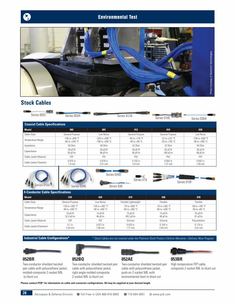
Series 034K
4-Conductor Cable SpecificationsModel 010 034 019 036 078
Cable Style General Purpose Low Noise Flexible Lightweight Flexible Flexible
Temperature Range -130 to +392 °F-90 to +200 °C
-130 to +392 °F-90 to +200 °C
-76 to +500 °F-60 to +260 °C
-76 to +392 °F-60 to +200 °C
-58 to +185 °F-50 to +85 °C
Capacitance 16 pF/ft52.4 pF/m
14 pF/ft46 pF/m
15 pF/ft49.2 pF/m
15 pF/ft48 pF/m
25 pF/ft81 pF/m
Cable Jacket Material FEP FEP Silicone Silicone Polyurethane
Cable Jacket (Diameter) 0.1 in2.54 mm
0.077 in1.96 mm
0.070 in1.77 mm
0.104 in2.64 mm
0.119 in3.02 mm
Series 010GSeries 010F
Series 002C Series 012A Series 018CSeries 003A
Series 030A
Series 034D
Coaxial Cable SpecificationsModel 002 003 012 018 030
Cable Style General Purpose Low Noise General Purpose General Purpose Low Noise
Temperature Range -130 to +400 °F-90 to +204 °C
-320 to +500 °F-196 to +260 °C
-40 to +176 °F-40 to +80 °C
-22 to +221 °F-30 to +105 °C
-130 to +500 °F-90 to +260 °C
Impedance 50 Ohm 50 Ohm 52 Ohm 32 Ohm 50 Ohm
Capacitance 29 pF/ft95 pF/m
30 pF/ft98 pF/m
29 pF/ft95 pF/m
55 pF/ft180 pF/m
30 pF/ft98 pF/m
Cable Jacket Material FEP TFE PVC PVC FEP
Cable Jacket Diameter 0.075 in1.9 mm
0.079 in2.01 mm
0.193 in4.9 mm
0.054 in1.37 mm
0.042 in1.09 mm
Industrial Cable Configurations*
052BRTwo-conductor shielded twistedpair cable with polyurethane jacket,molded-composite 2-socket MILto blunt cut
052BQTwo-conductor shielded twisted paircable with polyurethane jacket,right-angle molded composite 2-socket MIL to blunt cut
052AETwo-conductor shielded twisted paircable with polyurethane jacket,push-on 2-socket MIL withenvironmental boot to blunt cut
053BRHigh temperature FEP cable,composite 2-socket MIL to blunt cut
* Stock Cables are not covered under the Platinum Stock Product Lifetime Warranty + Delivery Now Program.
Series 036
Series 019
Stock Cables
Please contact PCB® for information on cable and connector configurations. All may be supplied at your desired length.
Phot
o Co
urte
sy o
f Spe
ctrum
Tech
nolog
ies
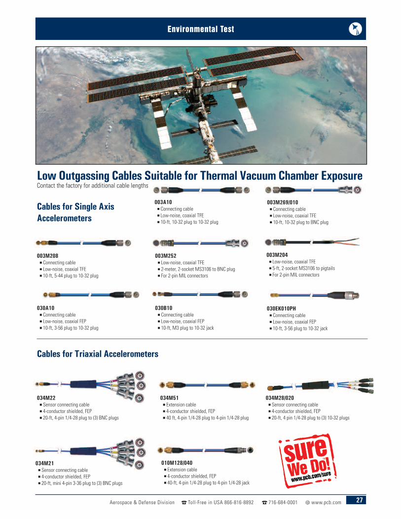
Environmental Test
Aerospace & Defense Division Toll-Free in USA 866-816-8892 716-684-0001 www.pcb.com 27
003A10n Connecting cablen Low-noise, coaxial TFEn 10-ft, 10-32 plug to 10-32 plug
034M51n Extension cablen 4-conductor shielded, FEPn 40 ft, 4-pin 1/4-28 plug to 4-pin 1/4-28 plug
010M128/040n Extension cablen 4-conductor shielded, FEPn 40-ft, 4-pin 1/4-28 plug to 4-pin 1/4-28 jack
003M208n Connecting cablen Low-noise, coaxial TFEn 10-ft, 5-44 plug to 10-32 plug
003M269/010n Connecting cablen Low-noise, coaxial TFEn 10-ft, 10-32 plug to BNC plug
003M252n Low-noise, coaxial TFEn 2-meter, 2-socket MS3106 to BNC plugn For 2-pin MIL connectors
003M204n Low-noise, coaxial TFEn 5-ft, 2-socket MS3106 to pigtailsn For 2-pin MIL connectors
030A10n Connecting cablen Low-noise, coaxial FEPn 10-ft, 3-56 plug to 10-32 plug
030B10n Connecting cablen Low-noise, coaxial FEPn 10-ft, M3 plug to 10-32 jack
030EK010PHn Connecting cablen Low-noise, coaxial FEPn 10-ft, 3-56 plug to 10-32 jack
Cables for Triaxial Accelerometers
034M22n Sensor connecting cablen 4-conductor shielded, FEPn 20-ft, 4-pin 1/4-28 plug to (3) BNC plugs
Cables for Single AxisAccelerometers
Low Outgassing Cables Suitable for Thermal Vacuum Chamber ExposureContact the factory for additional cable lengths
034M21n Sensor connecting cablen 4-conductor shielded, FEPn 20-ft, mini 4-pin 3-36 plug to (3) BNC plugs
034M28/020n Sensor connecting cablen 4-conductor shielded, FEPn 20-ft, 4 pin 1/4-28 plug to (3) 10-32 plugs

The Global Leader in Sensors and Instrumentation For All Your Applications
Toll-Free in USA 888-684-0014E-mail [email protected]
Toll-Free in USA 800-828-8840E-mail [email protected]
Toll-Free in USA 800-959-4464E-mail [email protected]
Toll-Free in USA 866-684-7107E-mail [email protected]
Please see these PCB Piezotronics catalogs for your other Aerospace & Defense applications:n Flight Testn Explosive, Gun and Impact Testing
3425 Walden Avenue, Depew, NY 14043-2495 USAToll-Free in USA 866-816-8892 n Fax 716-684-0987 n E-mail [email protected]
n Ground Testn OEM Capabilities
For our complete line of sensors, see our Test & Measurement Catalog.
Environmental TestMeasurements?
We Do!TM
Toll-Free in USA 800-860-4867E-mail [email protected]
Toll-Free in USA 888-258-3222E-mail [email protected]
Application
3425 Walden Avenue, Depew, NY 14043-2495 USAToll-Free in USA 866-816-8892
24-hour SensorLineSM 716-684-0001 Fax 716-684-0987 E-mail [email protected]
Web Site www.pcb.comAS9100 CERTIFIED n ISO 9001 CERTIFIED n A2LA ACCREDITED to ISO 17025
© 2015 PCB Group, Inc. In the interest of constant product improvement, specifications are subject to change withoutnotice. PCB, ICP, Modally Tuned, Spindler, Swiveler and TORKDISC are registered trademarks of PCB Group. SoundTrackLXT, Spark and Blaze are registered trademarks of PCB Piezotronics. SensorLine is a service mark of PCB Group. All othertrademarks are properties of their respective owners.
AD-ENVIRONMENTAL-0715 Printed in U.S.A.
The Aerospace & Defense division of PCB Piezotronics serves the Turbine Engine,Helicopter Health and Usage Monitoring (HUMS), Ground Vibration Test, Flight Test,Wind Tunnel Test, Fuze/Safe and Arm, Spacecraft and Aerospace Systems designand development communities with sensors and associated signal conditioning formeasurement of acceleration (vibration, shock and rigid body); acoustics; pressure;force; strain; and torque. Sensor technologies employed include piezoelectric,piezoresistive (both strain gauge and MEMS) and variable capacitive (both MEMSand microphone). Manufacturing operations are certified to AS9100:2004 and ISO9001:2000, with calibration procedures accredited by A2LA to ISO 17025. Productscan be manufactured to meet specific aerospace environmental standards, withprogram design requirements to meet RTCA-DO-160 and MIL-STD-810, and lowoutgassing designs available for specific applications.
Visit www.pcb.com to locate your nearest sales office