Embed Size (px)
Citation preview

Code: EO-MA-DMS-GS-0001
Issue: 4.13
Date: 05/04/2017
Name Function Signature
Prepared by: Fabrizio Pirondini
José Antonio González Abeytua
Juan José Borrego Bote
Carlos Villanueva
Project Engineer
Project Manager
Project Engineer
Project Manager
Checked by: Javier Babe Quality A. Manager
Approved by: Carlos Villanueva Project Manager
DEIMOS Space S.L.U.Ronda de Poniente, 19
Edificio Fiteni VI, Portal 2, 2ª Planta28760 Tres Cantos (Madrid), SPAIN
Tel.: +34 91 806 34 50Fax: +34 91 806 34 51
E-mail: [email protected]
© DEIMOS Space S.L.U.
All Rights Reserved. No part of this document may be reproduced, stored in a retrieval system, or transmitted, in any form or by any means, electronic, mechanical, photocopying, recording or otherwise, without the prior written
permission of DEIMOS Space S.L.U. or ESA.
Earth ObservationMission CFI Software
CONVENTIONS DOCUMENT

Code: EO-MA-DMS-GS-0001Date: 05/04/2017Issue: 4.13Page: 2
DOCUMENT INFORMATIONDOCUMENT INFORMATIONContract Data Classification
Contract Number: 15583/01/NL/GSInternal
Public
Contract Issuer: ESA / ESTECIndustry X
Confidential
External Distribution
Name Organization Copies
Electronic handling
Word Processor: LibreOffice 5.2.3.3
Archive Code: P/MCD/DMS/01/026-003
Electronic file name: eo-ma-dms-gs-001-12
Earth Observation Mission CFI Software. CONVENTIONS DOCUMENT

Code: EO-MA-DMS-GS-0001Date: 05/04/2017Issue: 4.13Page: 3
DOCUMENT STATUS LOGDOCUMENT STATUS LOGIssue Change Description Date Approval
1.0 New Document 27/10/09
4.1
• Issue in-line wit EOCFI libraries version
• Section 8.2.4 Refractive index added
• Section 8.5 Ray tracing added
07/05/10
4,2 EOCFI libraries version 4.2 31/01/11
4.3 EOCFI libraries version 4.3 31/01/11
4.4 EOCFI libraries version 4.4 05/07/12
4.5 EOCFI libraries version 4.5 01/03/13
4.6 EOCFI libraries version 4.6 03/10/13
4.7 EOCFI libraries version 4.7 28/03/14
4.8 EOCFI libraries version 4.8 29/10/14
4.9 EOCFI libraries version 4.9 23/04/15
4.10 EOCFI libraries version 4.10 29/10/15
4.11 EOCFI libraries version 4.11 15/04/16
4.12 EOCFI libraries version 4.12 03/11/16
4.13 EOCFI libraries version 4.13 05/04/17
Earth Observation Mission CFI Software. CONVENTIONS DOCUMENT

Code: EO-MA-DMS-GS-0001Date: 05/04/2017Issue: 4.13Page: 4
TABLETABLE OFOF CONTENTSCONTENTS
DOCUMENT INFORMATION.......................................................................................................... 2
DOCUMENT STATUS LOG............................................................................................................ 3
TABLE OF CONTENTS.................................................................................................................. 4
LIST OF TABLES............................................................................................................................ 8
LIST OF FIGURES.......................................................................................................................... 9
1 SCOPE........................................................................................................................................ 10
2 ACRONYMS AND NOMENCLATURE.......................................................................................11
2.1 Acronyms................................................................................................................................................. 11
3 APPLICABLE AND REFERENCE DOCUMENTS......................................................................13
3.1 Applicable Documents............................................................................................................................ 13
3.2 Reference Documents............................................................................................................................. 13
4 TIME REFERENCES AND MODELS.........................................................................................14
4.1 Time References..................................................................................................................................... 14
4.2 Time formats.......................................................................................................................................... 15
4.2.1 Earth Observation time formats........................................................................................................ 15
4.3 Time resolution...................................................................................................................................... 17
4.4 Earth Observation On-board times.....................................................................................................17
5 REFERENCE FRAMES.............................................................................................................. 18
5.1 General Reference Frames.................................................................................................................... 19
5.1.1 Galactic............................................................................................................................................. 19
5.1.2 Barycentric Mean of 1950................................................................................................................. 19
5.1.3 Barycentric Mean of 2000................................................................................................................. 19
5.1.4 Heliocentric Mean of 2000............................................................................................................... 19
Earth Observation Mission CFI Software. CONVENTIONS DOCUMENT

Code: EO-MA-DMS-GS-0001Date: 05/04/2017Issue: 4.13Page: 5
5.1.5 Geocentric Mean of 2000.................................................................................................................. 20
5.1.6 Mean of Date.................................................................................................................................... 20
5.1.7 True of Date...................................................................................................................................... 20
5.1.8 Pseudo Earth Fixed........................................................................................................................... 20
5.1.9 Earth Fixed........................................................................................................................................ 20
5.1.10 Topocentric..................................................................................................................................... 20
5.1.11 LIF (Launch Inertial Frame).......................................................................................................... 20
5.2 Satellite Reference Frames.................................................................................................................... 21
5.2.1 Satellite Orbital................................................................................................................................. 21
5.3 General Reference Frames Transformations.......................................................................................23
5.3.1 Galactic to Barycentric Mean of 1950.............................................................................................. 24
5.3.2 Barycentric Mean of 1950.0 to Barycentric Mean of 2000...............................................................25
5.3.3 Barycentric Mean of 2000 to Geocentric Mean of 2000...................................................................25
5.3.4 Heliocentric Mean of 2000 to Geocentric Mean of 2000..................................................................26
5.3.5 Geocentric Mean of 2000 to Mean of Date.......................................................................................26
5.3.6 Mean of Date to True of Date........................................................................................................... 27
5.3.7 True of Date to Pseudo Earth Fixed.................................................................................................. 28
5.3.8 Pseudo Earth Fixed to Earth Fixed.................................................................................................... 29
Figure 9: Transformation between PEF and EF reference frames...........................................................30
5.4 Satellite Reference Frames Transformations.......................................................................................30
6 ORBIT CHARACTERISATION...................................................................................................31
6.1 Orbit Definition....................................................................................................................................... 31
6.1.1 Sun-synchronous Orbit..................................................................................................................... 31
6.1.2 Quasi Sun-synchronous Orbit........................................................................................................... 31
6.1.3 Geo-synchronous Orbit..................................................................................................................... 31
6.2 Orbit Types............................................................................................................................................ 32
6.2.1 Reference Orbit................................................................................................................................. 32
6.2.2 Predicted Orbit.................................................................................................................................. 32
6.2.3 Restituted Orbit................................................................................................................................. 32
6.2.4 TLE Orbit.......................................................................................................................................... 32
6.3 Orbit Propagation Definition................................................................................................................ 32
Earth Observation Mission CFI Software. CONVENTIONS DOCUMENT

Code: EO-MA-DMS-GS-0001Date: 05/04/2017Issue: 4.13Page: 6
6.4 Orbit Propagation Models.................................................................................................................... 32
6.4.1 Mean Keplerian Orbit Propagator..................................................................................................... 33
6.4.1.1 Simulation mode......................................................................................................................... 33
6.4.2 Precise Orbit Propagator................................................................................................................... 33
6.4.3 TLE Propagator................................................................................................................................. 34
7 PARAMETERS............................................................................................................................ 35
7.1 Orbit Parameters................................................................................................................................... 35
7.1.1 Cartesian State Vector....................................................................................................................... 35
7.1.2 Orbit Radius, Velocity Magnitude and Components........................................................................35
7.1.3 Osculating Kepler State Vector......................................................................................................... 35
7.1.4 Mean Kepler State Vector................................................................................................................. 36
7.1.5 Equinoctial State Vector................................................................................................................... 36
7.1.6 Ascending Node, Ascending Node Time, Nodal Period, Absolute Orbit Number...........................36
7.1.7 Mean Local Solar Time Drift............................................................................................................ 37
7.1.8 Repeat Cycle and Cycle Length........................................................................................................ 37
7.1.9 Sub-satellite Point, Satellite Nadir and Ground Track......................................................................37
7.1.10 Mean Local Solar Time and True Local Solar Time.......................................................................37
7.1.10.1 Mean Local Solar Time............................................................................................................ 37
7.1.10.2 True Local Solar Time............................................................................................................. 38
7.1.11 Phase and Cycle.............................................................................................................................. 38
7.1.12 Absolute and Relative Orbit Number.............................................................................................. 38
7.1.13 Track Number................................................................................................................................. 38
7.1.14 Spacecraft Midnight........................................................................................................................ 39
7.2 Attitude Coordinate Systems Parameters............................................................................................ 39
7.2.1 Attitude determination parameters..................................................................................................... 39
7.2.2 Satellite Centered Direction.............................................................................................................. 41
7.3 Earth-related Parameters...................................................................................................................... 41
7.3.1 Geodetic Position.............................................................................................................................. 41
7.3.2 Earth Centered Direction.................................................................................................................. 44
7.3.3 Topocentric Direction....................................................................................................................... 44
7.4 Ground Station Parameters.................................................................................................................. 44
7.4.1 Ground Station Location................................................................................................................... 44
Earth Observation Mission CFI Software. CONVENTIONS DOCUMENT

Code: EO-MA-DMS-GS-0001Date: 05/04/2017Issue: 4.13Page: 7
7.4.2 Ground Station Visibility.................................................................................................................. 45
7.5 Target Parameters................................................................................................................................. 45
7.5.1 Moving and Earth-fixed Targets....................................................................................................... 45
7.5.2 Location Parameters.......................................................................................................................... 45
7.6 Sun and Moon Parameters.................................................................................................................... 45
7.7 Euler angles............................................................................................................................................ 46
8 MODELS..................................................................................................................................... 48
8.1 Attitude Modes....................................................................................................................................... 48
8.2 Earth....................................................................................................................................................... 49
8.2.1 Earth Position.................................................................................................................................... 49
8.2.2 Earth Geometry................................................................................................................................. 49
8.2.3 Earth Atmosphere............................................................................................................................. 50
8.2.3.1 US Standard Atmosphere 1976.................................................................................................. 50
8.2.4 Refractive index................................................................................................................................ 52
8.2.4.1 Edlen´s law................................................................................................................................. 52
8.2.5 Digital Elevation Models (DEM)...................................................................................................... 53
8.3 Sun and Moon........................................................................................................................................ 53
8.4 Stars........................................................................................................................................................ 53
8.4.1 Stars Positions................................................................................................................................... 54
8.5 Ray tracing.............................................................................................................................................. 56
8.5.1 No refraction model........................................................................................................................... 57
8.5.2 Refraction models.............................................................................................................................. 57
8.5.2.1 Standard atmosphere model........................................................................................................ 58
8.5.2.2 User’s atmosphere model............................................................................................................ 58
8.5.3 Predefined refraction corrective functions model.............................................................................58
9 UNITS.......................................................................................................................................... 60
Earth Observation Mission CFI Software. CONVENTIONS DOCUMENT

Code: EO-MA-DMS-GS-0001Date: 05/04/2017Issue: 4.13Page: 8
LISTLIST OFOF TABLESTABLESTable 1: Earth Observation time reference definitions...................................................................................14Table 2: Earth Observation time formats........................................................................................................ 16Table 3: Earth Observation reference frames usage.......................................................................................18Table 4: Attitude control modes..................................................................................................................... 48Table 5: WGS84 parameters........................................................................................................................... 49Table 6: Molecular-scale temperature coefficients.........................................................................................51Table 7: First step correction of star looking direction...................................................................................53Table 8: Second step corrections of star looking direction.............................................................................54Table 9: Units in CFI Software....................................................................................................................... 60
Earth Observation Mission CFI Software. CONVENTIONS DOCUMENT

Code: EO-MA-DMS-GS-0001Date: 05/04/2017Issue: 4.13Page: 9
LISTLIST OFOF FIGURES FIGURESFigure 1: Relationships between UT1, UTC and TAI....................................................................................14Figure 2: Satellite Orbital Frame.................................................................................................................... 22Figure 3: General Reference Frames Transformations...................................................................................23Figure 4: Galactic and Equatorial coordinates................................................................................................ 24Figure 5: Transformations between BM2000, HM2000 and GM2000 reference frames...............................26Figure 6: Transformation between GM200 and MoD reference frames.........................................................27Figure 7: Transformation between MoD and ToD reference frames..............................................................28Figure 8: Transformation between ToD and PEF reference frames...............................................................29Figure 9: Transformation between PEF and EF reference frames..................................................................30Figure 10: CFI-specific Reference Frames Transformations..........................................................................30Figure 11: Sun-synchronous and quasi Sun-synchronous orbits descriptions................................................31Figure 12: Azimuth and elevation definition.................................................................................................. 41Figure 13: Geodetic position.......................................................................................................................... 42Figure 14: Earth centred direction.................................................................................................................. 44Figure 15: Topocentric direction.................................................................................................................... 44Figure 16: Euler Angles.................................................................................................................................. 47Figure 17: Satellite aberration........................................................................................................................ 56Figure 18: Ray path........................................................................................................................................ 57
Earth Observation Mission CFI Software. CONVENTIONS DOCUMENT
Code: EO-MA-DMS-GS-0001Date: 05/04/2017Issue: 4.13Page: 10
11 SCOPESCOPE
This document describes in detail the time references and formats, reference frames, parameters, models, and units that will be used by the Earth Observation Mission CFI Software. The description sometimes goes beyond the CFI-needed information, when deemed necessary for the sake of a correct explanation.
All topics treated along the document are applicable to the following CFI libraries:• EO_DATA_HANDLING• EO_LIB• EO_ORBIT• EO_POINTING• EO_VISIBILITY
The present document covers the different LEO satellite missions considered in the frame of the ESA Earth Observation Programme.
Earth Observation Mission CFI Software. CONVENTIONS DOCUMENT

Code: EO-MA-DMS-GS-0001Date: 05/04/2017Issue: 4.13Page: 11
22 ACRONYMS AND NOMENCLATUREACRONYMS AND NOMENCLATURE
2.12.1 AcronymsAcronyms
ADM Atmospheric Dynamics Mission
ANX Ascending Node Crossing
AOCS Attitude and Orbit Control Sub-system
CFI Customer Furnished Item
DORIS Doppler Orbitography and Radio positioning Integrated by Satellite
ESA European Space Agency
ESTEC European Space Technology and Research Centre
EO Earth Observation
EOCFI Earth Observation CFI Software
FK4 Fourth Fundamental Catalogue
FK5 Fifth Fundamental Catalogue
GOCE Gravity Field and Steady-state Ocean Circulation Mission
GPS Global Positioning System
IAU International Astronomical Union
IERS International Earth Rotation Service
IRF Instrument Reference Frame
IRM IERS Reference Meridian
IRP IERS Reference Pole
ITRF IERS Terrestrial Reference Frame
JD Julian Day
LOS Line of Sight
LNP Local Normal Pointing
MLST Mean Local Solar Time
MJD2000 Modified Julian Day of 2000
OBT On-Board Time
Earth Observation Mission CFI Software. CONVENTIONS DOCUMENT

Code: EO-MA-DMS-GS-0001Date: 05/04/2017Issue: 4.13Page: 12
SBT Satellite Binary Time
SGP4 Simplified General Perturbations Satellite Orbit Model 4
SNRF Satellite Nominal Reference Frame
SOF Satellite Orbital Frame
SRF Satellite Reference Frame
S/C Spacecraft
SI International System of Units
SSP Sub-Satellite Point
TAI International Atomic Time
TLE Two Line Elements
TLST True Local Solar Time
UT1 Universal Time UT1
UTC Coordinated Universal Time
YSM Yaw Steering Mode
Earth Observation Mission CFI Software. CONVENTIONS DOCUMENT

Code: EO-MA-DMS-GS-0001Date: 05/04/2017Issue: 4.13Page: 13
33 APPLICABLE AND REFERENCE DOCUMENTSAPPLICABLE AND REFERENCE DOCUMENTS
3.13.1 Applicable DocumentsApplicable Documents
3.23.2 Reference DocumentsReference Documents
ALMAN95 The Astronomical Almanac for the year 1995.
ALMAN05 The Astronomical Almanac for the year 2005.
BOWRING Method of Bowring. NGT Geodesia 93-7. P 333-335. 1993.
CELES www.celestrak.com
FLANDERN Low-precision formulae for planetary positions. Astrophysical Journal Supplement Series: 41. P 391-411. T.C.Van Flandern, K.F. Pulkkinen. November 1979.
GREEN Spherical Astronomy. Green, R.M. 1985
HEISKANEN Physical Geodesy. Weikko A. Heiskanen, Helmut Moritz. Graz 1987.
IERS_SUPL Explanatory Supplement to IERS Bulletins A and B. International Earth Rotation Service (IERS). March 1995.
KLINKRAD Semi-Analytical Theory for Precise Single Orbit Predictions of ERS-1. ER-RP- ESA-SY-004. H.K. Klinkrad (ESA/ESTEC/WMM). Issue 1.0. 28/06/87.
LIU_ALFORD Semianalytic Theory for a Close-Earth Artificial Satellite. Journals of Guidance and Control Vol. 3, No 4. J.J.F. Liu and R.L. Alford. July-August 1980.
MCD_SP Earth Observation Mission CFI Software MISSION SPECIFIC CUSTOMIZATIONS. EO-MA-DMS-GS-018. Issue 1.0 27/10/2009
OAD_TIME OAD Standards: Time and Coordinate Systems for ESOC Flight Dynamics Operations. Orbit Attitude Division, ESOC. Issue 1. May 1994.
STD76 U.S. Standard Atmosphere 1976. National Oceanic and Atmosphere Administration.
EDLEN “Handbook of geophysics and the space environment”. Adolph S. Jursa. Air Force Geophysics Laboratory, 1985.
Earth Observation Mission CFI Software. CONVENTIONS DOCUMENT
Code: EO-MA-DMS-GS-0001Date: 05/04/2017Issue: 4.13Page: 14
44 TIME REFERENCES AND MODELSTIME REFERENCES AND MODELS
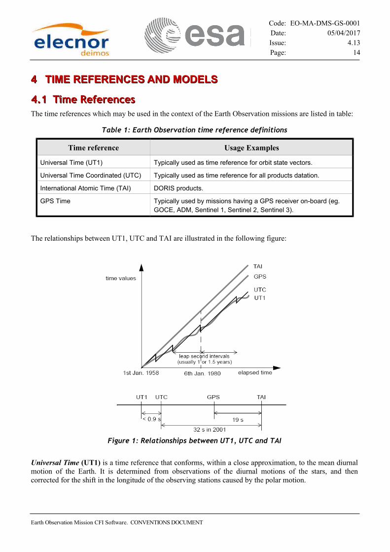
4.14.1 Time References Time ReferencesThe time references which may be used in the context of the Earth Observation missions are listed in table:
Table 1: Earth Observation time reference definitions
Time reference Usage Examples
Universal Time (UT1) Typically used as time reference for orbit state vectors.
Universal Time Coordinated (UTC) Typically used as time reference for all products datation.
International Atomic Time (TAI) DORIS products.
GPS Time Typically used by missions having a GPS receiver on-board (eg. GOCE, ADM, Sentinel 1, Sentinel 2, Sentinel 3).
The relationships between UT1, UTC and TAI are illustrated in the following figure:
Universal Time (UT1) is a time reference that conforms, within a close approximation, to the mean diurnal motion of the Earth. It is determined from observations of the diurnal motions of the stars, and then corrected for the shift in the longitude of the observing stations caused by the polar motion.
Earth Observation Mission CFI Software. CONVENTIONS DOCUMENT
Figure 1: Relationships between UT1, UTC and TAI

Code: EO-MA-DMS-GS-0001Date: 05/04/2017Issue: 4.13Page: 15
The time system generally used is the Coordinated Universal Time (UTC), previously called Greenwich Mean Time. The UTC is piece wise uniform and continuous, i.e. the time difference between UTC and TAI is equal to an integer number of seconds and is constant except for occasional jumps from inserted integer leap seconds. The leap seconds are inserted to cause UTC to follow the rotation of the Earth, which is expressed by means of the non uniform time reference Universal Time UT1.
If UT1 is predicted to lag behind UTC by more than 0.9 seconds, a leap second is inserted. The message is distributed in a Special Bulletin C by the International Earth Rotation Service (IERS).
The insertion of leap seconds is scheduled to occur with first preference at July 1st and January 1st at 00:00:00 UTC, and with second preference at April 1st and October 1st at 00:00:00 UTC.
∆UT1 = UT1 - UTC is the increment to be applied to UTC to give UT1, expressed with a precision of 0.1 seconds, and which is broadcasted, and any change announced in a Bulletin D, by the IERS1.
DUT1 is the predicted value of ∆UT1. Predictions of UT1 - UTC daily up to ninety days, and at monthly intervals up to a year in advance, are included in a Bulletin A which is published weekly by the IERS.
International Atomic Time (TAI) represents the mean of readings of several atomic clocks, and its fundamental unit is exactly one SI second at mean sea level and is, therefore, constant and continuous.
∆TAI = TAI - UTC is the increment to be applied to UTC to give TAI.
GPS Time is an atomic clock time similar to but not the same as UTC time. It is synchronised to UTC but the main difference relies in the fact that GPS time does not introduce any leap second. Thus, the introduction of UTC leap second causes the GPS time and UTC time to differ by a known integer number of cumulative leap seconds; i.e. the leap seconds that have been accumulated since GPS epoch in midnight January 5, 1980.
∆GPS = TAI - GPS is the increment to be applied to GPS to give TAI, being a constant value of 19 seconds.
4.24.2 Time formats Time formatsThe Julian Day (JD) is the interval of time in days and fraction of a day since 4713 BC January 1 at Greenwich noon (12:00:00).
The Modified Julian Day 2000 (MJD2000) is the interval of time in days and fraction of day since 2000 January 1 at 00:00:00.
JD = MJD2000 + 2451544.5 [decimal days]
The time format year, month, day of month, hour, minute and second follows the Gregorian calendar.
4.2.14.2.1 Earth Observation time formats Earth Observation time formatsThe time formats used with the time references proposed in section 4.1 can be one of the following:
• Processing• Transport • ASCII
1 ∆UT1 usually changes 1-2 ms per day
Earth Observation Mission CFI Software. CONVENTIONS DOCUMENT

Code: EO-MA-DMS-GS-0001Date: 05/04/2017Issue: 4.13Page: 16
Table 2: Earth Observation time formats
Time format Description Usage
Processing 64-bits floating point number, for decimal days
Internal processing, such as product processing sequences. Only for continuous times, i.e. TAI
Transport EO CFI Standard Three 32-bits integer numbers for days, seconds and microseconds2
Time values exchange between computers
ASCII3 Standard Text string: “yyyy-mm-dd_hh:mm:ss“
Standard with reference Text string: “RRR=yyyy-mm-dd_hh:mm:ss“
Standard with microseconds
Text string: “yyyy-mm- dd_hh:mm:ss.uuuuuu“
Standard with reference and microseconds
Text string: “RRR=yyyy-mm- dd_hh:mm:ss.uuuuuu“
Compact Text string: “yyyymmdd_hhmmss“
Compact with reference Text string: “RRR=yyyymmdd_hhmmss“
Compact with microseconds
Text string: “yyyymmdd_hhmmssuuuuuu“
Compact with reference and microseconds
Text string: “RRR=yyyymmdd_ hhmmssuuuuuu“
CCSDS-A Text string: “yyyy-mm-ddThh:mm:ss“
CCSDS-A with reference Text string: “RRR=yyyy-mm-ddThh:mm:ss“
CCSDS-A with microseconds
Text string: “yyyy-mm- ddThh:mm:ss.uuuuuu“
CCSDS-A with reference and microseconds
Text string: “RRR=yyyy-mm- ddThh:mm:ss.uuuuuu“
Readable input/output, such as file headers, log messages, ...
2 This is the EO CFI Standard Transport Format. Additional Transport Formats have been defined for specific missions, see [MCD_SP].
3 These are the EO CFI Standard ASCII Formats. Additional ASCII Formats have been defined for specific missions, see [MCD_SP].
Earth Observation Mission CFI Software. CONVENTIONS DOCUMENT

Code: EO-MA-DMS-GS-0001Date: 05/04/2017Issue: 4.13Page: 17
4.34.3 Time resolution Time resolutionThe time resolution is one microsecond.
4.44.4 Earth Observation On-board times Earth Observation On-board timesThe On Board Time is the time maintained by the Spacecraft and is the time reference for all spacecraft on-board activities. Depending upon the purpose and requirements of the mission, the time format used on- board the satellite will be different. See [MCD_SP] for mission specific on-board time definitions.
Earth Observation Mission CFI Software. CONVENTIONS DOCUMENT

Code: EO-MA-DMS-GS-0001Date: 05/04/2017Issue: 4.13Page: 18
55 REFERENCE FRAMESREFERENCE FRAMES
The following reference frames are used in the context of Earth Observation missions:
Table 3: Earth Observation reference frames usage
Reference frame Usage Examples
Galactic Star position and velocities can be given in this reference frame
Barycentric Mean of 1950 Some star catalogues use this reference frame to express the positions of their stars.
Barycentric Mean of 2000 The star catalogues usually use this reference frame to express the positions of their stars.
Heliocentric Mean of 2000 The ephemeris of the planets are usually expressed in this reference frame.
Geocentric Mean of 2000 The FOCC performs the internal calculations related to the predicted and restituted orbits in this reference frame.
Mean of Date The Mean Local Solar Time is defined in this reference frame.
True of Date It is the inertial reference frame used for input and output in the CFI software (e.g. star positions).
Earth fixed It is the reference frame used for input and output of the satellite state vector (i.e. orbit definition), and for the output for geolocation in the CFI software.
Pseudo Earth Fixed It is similar to Earth Fixed but without considering polar motion rotation.
Topocentric It is the local horizontal reference frame used to define a looking direction.
Satellite Orbital It is a reference frame centred in the satellite and defined by the satellite position and velocity. Its used as a reference for the application of the selected attitude control mode.
Satellite Nominal Attitude It is used for the attitude determination. It is based on relation with the Satellite Orbital frame.
Satellite Attitude It is used for the attitude determination as well. It is based on relation the Satellite Nominal Attitude frame or on measurements.
Instrument Attitude It is the reference frame that constitutes the reference for the definition of a look direction relative to the satellite (e.g. to express the pointing of an instrument).
Earth Observation Mission CFI Software. CONVENTIONS DOCUMENT

Code: EO-MA-DMS-GS-0001Date: 05/04/2017Issue: 4.13Page: 19
5.15.1 General Reference Frames General Reference Frames
5.1.15.1.1 Galactic GalacticThe galactic plane is determined by the statistical study of the galactic dynamics. In this reference frame, position are determined by a galactic latitude and longitude. The galactic latitude are taken as the angle measured from the galactic plane, while the galactic longitude are measured from the direction of the galactic centre.
In order to relate the galactic coordinates of a star to its equatorial coordinates, it is necessary to know the position of the galactic pole and the position of the galactic centre. These points have been adopted as follow, for the epoch 1950.0:
Right ascension of the Galactic pole = 12h 49m.
Declination of the Galactic pole = 27º.4.
Galactic longitude of the north celestial pole = 123º (also known as the position angle of the galactic centre)
5.1.25.1.2 Barycentric Mean of 1950 Barycentric Mean of 1950It is based on the star catalogue FK4 for the epoch B1950, since the directions of its axes are defined relatively to a given number of that star catalogue positions and proper motions.
The centre of this reference frame is the barycentre of the Solar System. The x-y plane coincides with the predicted mean Earth equatorial plane at the epoch B1950, and the x-axis points towards the predicted mean vernal equinox. The latter is the intersection of the mean equator plane with the mean ecliptic, and the ecliptic is the orbit of the Earth around the Sun. The z-axis points towards north.
The word mean indicates that the relatively short periodic nutations of the Earth are smoothed out in the calculation of the mean equator and equinox.
5.1.35.1.3 Barycentric Mean of 2000 Barycentric Mean of 2000It is based, according to the recommendations of the International Astronomical Union (IAU), on the star catalogue FK5 for the epoch J2000.0, since the directions of its axes are defined relatively to a given number of that star catalogue positions and proper motions.
The accuracy of this reference system, realized through the FK5 star catalogue, is approximately 0.1’’.
The centre of this reference frame is the barycentre of the Solar System. The x-y plane coincides with the predicted mean Earth equatorial plane at the epoch J2000.0, and the x-axis points towards the predicted mean vernal equinox. The latter is the intersection of the mean equator plane with the mean ecliptic, and the ecliptic is the orbit of the Earth around the Sun. The z-axis points towards north.
The word mean indicates that the relatively short periodic nutations of the Earth are smoothed out in the calculation of the mean equator and equinox.
5.1.45.1.4 Heliocentric Mean of 2000 Heliocentric Mean of 2000It is obtained by a parallel translation of the Barycentric Mean of 2000.0 reference frame from the barycenter of the Solar System to the centre of the Sun.
Earth Observation Mission CFI Software. CONVENTIONS DOCUMENT

Code: EO-MA-DMS-GS-0001Date: 05/04/2017Issue: 4.13Page: 20
5.1.55.1.5 Geocentric Mean of 2000 Geocentric Mean of 2000It is obtained by a parallel translation of the Barycentric Mean of 2000.0 reference frame from the barycenter of the Solar System to the centre of the Earth.
5.1.65.1.6 Mean of Date Mean of DateThe centre of this reference frame is the centre of the Earth. The x-y plane and the x-axis are defined by the mean Earth equatorial plane and the mean vernal equinox of date. The expression mean of date means that the system of coordinate axes are rotated with the Earth´s precession from J2000.0 to the date used as epoch. The z-axis points towards north.
The precession of the Earth is the secular effect of the gravitational attraction from the Sun and the Moon on the equatorial bulge of the Earth.
5.1.75.1.7 True of Date True of DateThe centre of this reference frame is the centre of the Earth. The x-y plane and the x-axis are defined by the true Earth equatorial plane and the true vernal equinox of date. The expression true of date indicates the instantaneous Earth equatorial plane and vernal equinox. The transformation from the Mean of Date to the True of Date is the adopted model of the nutation of the Earth.
The nutation is the short periodic effect of the gravitational attraction of the Moon and, to a lesser extent, the planets on the Earth’s equatorial bulge.
5.1.85.1.8 Pseudo Earth Fixed Pseudo Earth FixedIt is defined the same way as Earth Fixed reference frame. The difference is that polar motion rotation is not considered in this case.
5.1.95.1.9 Earth Fixed Earth FixedThe Earth fixed reference frame in use is the IERS Terrestrial Reference Frame (ITRF).
The zero longitude or IERS Reference Meridian (IRM), as well as the IERS Reference Pole (IRP), are maintained by the International Earth Rotation Service (IERS), based on a large number of observing stations, and define the IERS Terrestrial Reference Frame (ITRF).
5.1.105.1.10 Topocentric TopocentricIts z-axis coincides with the normal vector to the Earth’s Reference Ellipsoid, positive towards zenith. The x-y plane is the plane orthogonal to the z-axis, and the x-axis and y-axis point positive, respectively, towards east and north.
5.1.115.1.11 LIF LIF (Launch Inertial Frame) (Launch Inertial Frame)The Launch Inertial Frame (LIF) is an Coordinate System whose Z axis and XY plane are the same as Z axis and XY plane of Earth Fixed Coordinate System. It is a user defined Coordinate System as the user needs to provide a longitude and a UTC time to define it. More precisely, X,Y and Z axes are defined as follows:
• X axis: is in the equatorial plane and points where a given user defined meridian was at a given user defined UTC time. The meridian is defined by the user specifying the value of the corresponding longitude (note that, if longitude = 0, the reference is the Greenwich meridian)
Earth Observation Mission CFI Software. CONVENTIONS DOCUMENT

Code: EO-MA-DMS-GS-0001Date: 05/04/2017Issue: 4.13Page: 21
• Z axis: is in the direction of the angular velocity of the Earth (= towards North Pole)
• Y axis: complete the right-handed coordinate system
5.25.2 Satellite Reference Frames Satellite Reference FramesFour levels of reference frames are used for attitude determination:
• The Satellite Orbital frame (SOF)• Satellite Nominal reference frame (SNRF)• Satellite reference frame (SRF)• Instrument reference frame (IRF)
The SOF is used for the computation of the other satellite reference frames (see section 5.2.1 for the definition of this frame)
The SNRF is an ideal attitude model. The axis definition for this frame depends on the attitude model chosen for the satellite. Let’s see two examples:
• Local Normal Pointing attitude (LNP), the z-axis is chosen in the direction of the satellite’s zenith and the x-axis is defined in the direction of the satellite’s inertial velocity vector (in True of Date).
• Yaw Steering Mode attitude (YSM): the z-axis is chosen in the direction of the satellite’s zenith and the x-axis is defined in the direction of the satellite’s velocity vector in the Earth Fixed CS.
A complete list of attitude models can be seen in section 8.1.
The SRF corresponds to the satellite actual (measured) attitude frame. It could be considered as the result of three consecutive rotations of the SNRF over three angles called mispointing angles. The time derivative of those mispointing angles are called mispointing rates.
Finally the IRF is a frame based on an instrument of the satellite. There exists one reference frame per instrument and it is used for location and looking direction from the instrument.
5.2.15.2.1 Satellite Orbital Satellite OrbitalIt is a reference frame centred on the satellite and is defined by the Xs, Ys and Zs axes, which are specified relatively to the reference inertial reference frame, namely the True of Date.
The Zs axis points along the radial satellite direction vector, positive from the centre of the TOD reference frame towards the satellite, the Ys axis points along the transversal direction vector within the osculating orbital plane (i.e the plane defined by the position and velocity vectors of the satellite), orthogonal to the Zs axis and opposed to the direction of the orbital motion of the satellite. The Xs axis points towards the out-of-plane direction vector completing the right hand reference frame.
Z=r
∣r∣ X =
r ∧ v∣r ∧ v∣
Y =Z ∧ X
where X , Y and Z are the unitary direction vectors in the (Xs, Ys, Zs) axes, and r and v are the position and velocity vectors of the satellite expressed in the inertial reference frame.
Next drawing depicts the Satellite Orbital frame:
Earth Observation Mission CFI Software. CONVENTIONS DOCUMENT

Code: EO-MA-DMS-GS-0001Date: 05/04/2017Issue: 4.13Page: 22
Earth Observation Mission CFI Software. CONVENTIONS DOCUMENT
Figure 2: Satellite Orbital Frame

Code: EO-MA-DMS-GS-0001Date: 05/04/2017Issue: 4.13Page: 23
5.35.3 General Reference Frames TransformationsGeneral Reference Frames TransformationsThe following picture identifies the general reference frames transformations that are relevant for the Earth Observation missions.
Those transformation are described in the following sections.
Note that whenever a transformation is expressed as a sequence of rotations, the following expressions apply (the angle w is regarded positive):
RX (w)=[1 0 00 cos w sin w0 −sin w cosw] RY (w)=[
cos w 0 −sin w0 1 0
sin w 0 cos w ] RZ (w)=[cosw sin w 0
−sin w cos w 00 0 1]
Earth Observation Mission CFI Software. CONVENTIONS DOCUMENT
Figure 3: General Reference Frames Transformations
Code: EO-MA-DMS-GS-0001Date: 05/04/2017Issue: 4.13Page: 24
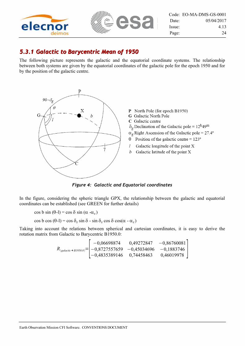
5.3.15.3.1 Galactic to Barycentric Mean of 1950 Galactic to Barycentric Mean of 1950The following picture represents the galactic and the equatorial coordinate systems. The relationship between both systems are given by the equatorial coordinates of the galactic pole for the epoch 1950 and for by the position of the galactic centre.
In the figure, considering the spheric triangle GPX, the relationship between the galactic and equatorial coordinates can be established (see GREEN for further details)
cos b sin (q-l) = cos d sin (a -ag )
cos b cos (q-l) = cos dg sin d - sin dg cos d cos(a - ag )
Taking into account the relations between spherical and cartesian coordinates, it is easy to derive the rotation matrix from Galactic to Barycentric B1950.0:
R(galactic→ B1950.0 )=[−0,06698874 0,49272847 −0,86760081
−0,8727557659 −0,45034696 −0,1883746−0,4835389146 0,74458463 0,46019978 ]
Earth Observation Mission CFI Software. CONVENTIONS DOCUMENT
Figure 4: Galactic and Equatorial coordinates

Code: EO-MA-DMS-GS-0001Date: 05/04/2017Issue: 4.13Page: 25
5.3.25.3.2 Barycentric Mean of 1950.0 to Barycentric Mean of 2000 Barycentric Mean of 1950.0 to Barycentric Mean of 2000The transformation from barycentric B1950.0 to barycentric J2000 includes the following processes:
1. Removal of the terms of elliptic aberration. 2. Rotation to the dynamical equinox of B1950.0 3. Correcting the proper motions for the equinox motion and the change in the value of precession 4. Changing from tropical to Julian centuries for the time scale of proper motions 5. Updating of positions to the epoch of J2000 6. Precession of positions and proper motions from B1950.0 to J2000.
For further details about this transformation, refer to:− ALMAN05(B32) − Astronomical and Astrophysical Journal 128, 263-267 (1983)
5.3.35.3.3 Barycentric Mean of 2000 to Geocentric Mean of 2000 Barycentric Mean of 2000 to Geocentric Mean of 2000The transformation from the Barycentric Mean of 2000 to the Geocentric Mean of 2000 reference frame is calculated with the following expressions (Figure 4 ):
where rE and vE are the position and velocity vectors in the Geocentric Mean of 2000 reference frame, rB and vB are the position and velocity vectors in the Barycentric Mean of 2000 reference frame, and r B, Earth and vB,Earth are the position and velocity vectors of the Earth in the Barycentric Mean of 2000
reference frame.
r B, Earth and vB,Earth are calculated according to BOWRING reference.
Earth Observation Mission CFI Software. CONVENTIONS DOCUMENT

Code: EO-MA-DMS-GS-0001Date: 05/04/2017Issue: 4.13Page: 26
5.3.45.3.4 Heliocentric Mean of 2000 to Geocentric Mean of 2000 Heliocentric Mean of 2000 to Geocentric Mean of 2000The transformation from the Heliocentric Mean of 2000 to the Geocentric Mean of 2000 reference frame is calculated with the following expressions (Figure 5):
where r E and vE are the position and velocity vectors in the Geocentric Mean of 2000 reference frame, r H and vH are the position and velocity vectors in the Heliocentric Mean of 2000 reference frame, and r H, Earth and vH,Earth are the position and velocity vectors of the Earth in the Heliocentric Mean of 2000
reference frame.
r H, Earth and vH,Earth are calculated according to BOWRING reference.
5.3.55.3.5 Geocentric Mean of 2000 to Mean of Date Geocentric Mean of 2000 to Mean of DateThe transformation from the Geocentric Mean of 2000 to the Mean of Date reference frame is performed with the following expression (Figure 6):
Earth Observation Mission CFI Software. CONVENTIONS DOCUMENT
Figure 5: Transformations between BM2000, HM2000 and GM2000 reference frames

Code: EO-MA-DMS-GS-0001Date: 05/04/2017Issue: 4.13Page: 27
where r m and r J2000 are the position vector in the Mean of Date and the Mean of 2000 reference frame, respectively.
The rotation angles of the precession model are calculated as follows (OAD_TIME reference):
ξ=0.6406161T+0.0000839T2+0.0000050T3
[deg ]
z=0.6406161T+0.0003041T2+0.0000051T3
[deg ]
ϑ=0.5567530T−0.0001185T2−0.0000116T 3
[deg ]
where T is the TDB time expressed in the Julian centuries format (1 Julian century = 36525 days).
However, the precession motion is so slow that the UTC time can be used instead of the TDB time, and therefore T can be calculated from t, the UTC time expressed in the MJD2000 format, with the following expression:
T = (t - 0.5)/36525 [Julian centuries]
5.3.65.3.6 Mean of Date to True of Date Mean of Date to True of DateThe transformation from the Mean of Date to the True of Date reference frame is performed with the following expression (Figure 7):
Earth Observation Mission CFI Software. CONVENTIONS DOCUMENT
Figure 6: Transformation between GM200 and MoD reference frames

Code: EO-MA-DMS-GS-0001Date: 05/04/2017Issue: 4.13Page: 28
where r t and r m are, respectively, the position vector in the True of Date and the Mean of Date reference frame.
The rotation angles of the simplified nutation model are calculated with (OAD_TIME reference):
where ε is the obliquity of the ecliptic at the epoch J2000:
ε = 23.439291 [deg]
and δ ε and δ ψ is expressed by the Wahr model taking only the nine largest terms, and using UT1 instead of TDB as the time reference.
5.3.75.3.7 True of Date to Pseudo Earth Fixed True of Date to Pseudo Earth FixedThe transformation from the True of Date to the Pseudo Earth fixed reference frame is performed with the following expression (Figure 8):
r pe=R z (H) r t
where r pe and r t are, respectively, the position vector in the Pseudo Earth fixed and in the True of Date reference frames.
The Earth rotation angle H is the sum of the Greenwich sidereal angle and a small term from the nutation in the longitude of the equinox.
The Greenwich sidereal angle moves with the daily rotation of the Earth and is calculated with the Newcomb’s formula according to international conventions as a third order polynomial, although the third order term will be neglected in our calculations.
The nutation term is calculated with the simplified nutation model (see section 5.1.7).
Earth Observation Mission CFI Software. CONVENTIONS DOCUMENT
Figure 7: Transformation between MoD and ToD reference frames

Code: EO-MA-DMS-GS-0001Date: 05/04/2017Issue: 4.13Page: 29
H =G+δ μ
G=99.96779469+360.9856473662860T+0.29079 x 10⁻¹²T 2[deg ]
where T is the UT1 time expressed in the MJD2000 format.
Note that the transformation from the Mean of Date to the Pseudo Earth fixed reference frame can be performed in one step being the dm rotation term cancelled out:
r pe=R z(G) R x(−δε) Ry (δ υ) r qm
5.3.85.3.8 Pseudo Earth Fixed to Earth Fixed Pseudo Earth Fixed to Earth FixedThe transformation from the Pseudo Earth Fixed to the Earth fixed reference frame is performed with the following expression (Figure 9):
r EF=Ry(−X)Rx (−Y) r PEF
where r EF and r PEF are, respectively, the position vector in the Earth fixed and in the Pseudo Earth Fixed reference frames; X and Y are the polar motion parameters (measured and predicted by the IERS).
Earth Observation Mission CFI Software. CONVENTIONS DOCUMENT
Figure 8: Transformation between ToD and PEF reference frames

Code: EO-MA-DMS-GS-0001Date: 05/04/2017Issue: 4.13Page: 30
Figure Figure 99: : Transformation between PEF and EF reference framesTransformation between PEF and EF reference frames
5.45.4 Satellite Reference Frames TransformationsSatellite Reference Frames TransformationsThere is not a general rule for transforming from one satellite reference frame to another. The attitude computation provides the transformation matrix from the satellite frame to an inertial reference frame. The following picture identifies the CFI-specific reference frames transformations that are relevant for the Earth Observation missions:
Earth Observation Mission CFI Software. CONVENTIONS DOCUMENT
Figure 10: CFI-specific Reference Frames Transformations
Code: EO-MA-DMS-GS-0001Date: 05/04/2017Issue: 4.13Page: 31
66 ORBIT CHARACTERISATIONORBIT CHARACTERISATION
6.16.1 Orbit DefinitionOrbit Definition
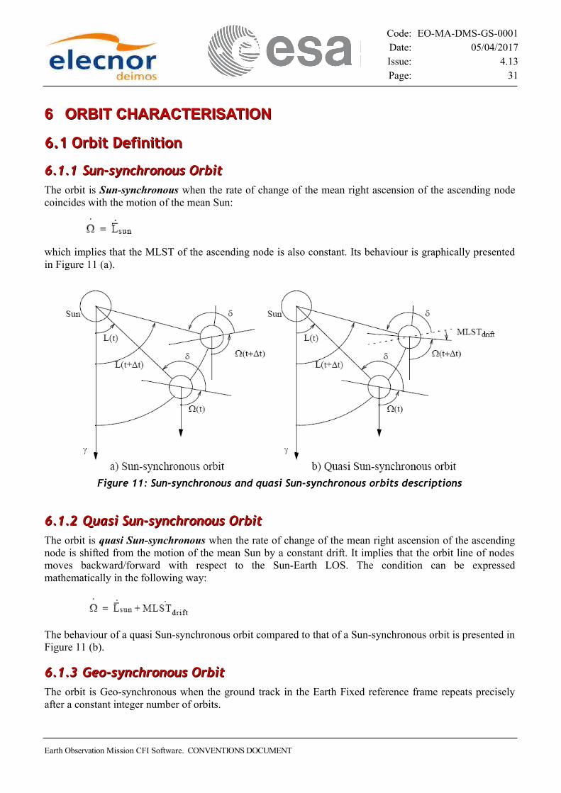
6.1.16.1.1 Sun-synchronous Orbit Sun-synchronous OrbitThe orbit is Sun-synchronous when the rate of change of the mean right ascension of the ascending node coincides with the motion of the mean Sun:
which implies that the MLST of the ascending node is also constant. Its behaviour is graphically presented in Figure 11 (a).
6.1.26.1.2 Quasi Sun-synchronous Orbit Quasi Sun-synchronous OrbitThe orbit is quasi Sun-synchronous when the rate of change of the mean right ascension of the ascending node is shifted from the motion of the mean Sun by a constant drift. It implies that the orbit line of nodes moves backward/forward with respect to the Sun-Earth LOS. The condition can be expressed mathematically in the following way:
The behaviour of a quasi Sun-synchronous orbit compared to that of a Sun-synchronous orbit is presented in Figure 11 (b).
6.1.36.1.3 Geo-synchronous Orbit Geo-synchronous OrbitThe orbit is Geo-synchronous when the ground track in the Earth Fixed reference frame repeats precisely after a constant integer number of orbits.
Earth Observation Mission CFI Software. CONVENTIONS DOCUMENT
Figure 11: Sun-synchronous and quasi Sun-synchronous orbits descriptions

Code: EO-MA-DMS-GS-0001Date: 05/04/2017Issue: 4.13Page: 32
6.26.2 Orbit Types Orbit Types
6.2.16.2.1 Reference Orbit Reference OrbitThe reference orbit consists of a scenario file, containing orbit information per repeat cycle change, i.e. the position and velocity vectors expressed in the Earth fixed reference frame, corresponding to the ascending node of that orbit and its associated time.
This state vector of the ascending node is calculated using the satellite-specific propagation mode, and imposing the conditions pertained the particular orbit definition.
6.2.26.2.2 Predicted Orbit Predicted OrbitThe predicted orbit consists of a set of satellite Cartesian state vectors that allow the computation of state vectors in the future with respect to the time in which the set has been generated.
6.2.36.2.3 Restituted Orbit Restituted OrbitThe restituted orbit consists of a set of consolidated satellite Cartesian state vectors that allow the computation of state vectors in the past with respect to the time in which the set has been generated.
6.2.46.2.4 TLE Orbit TLE OrbitThe TLE orbit consists of two 69-character lines of data. The TLE contains mean keplerian elements for a given epoch (More info about TLE format can be found in CELES).
6.36.3 Orbit Propagation Definition Orbit Propagation DefinitionTo calculate the state vector at any point in the orbit, it is sufficient to have the orbital data (a state vector, or keplerian elements) at a given time, and then propagate that initial state vector to the required time using an orbit propagation model.
That initial orbital data can come from different sources (see section 6.2) and depending on the type of orbit and the satellite mission, there are different requirements on the accuracy of the position and velocity vectors of that initial state.
6.46.4 Orbit Propagation Models Orbit Propagation ModelsThe propagation models must incorporate an initialisation mode. It basically starts with:
• a TLE providing the mean keplerian elements at a given epoch.• an initial cartesian state vector expressed in the Earth fixed reference frame at a given time, supplied
externally (see section 6.2), to calculate the time and the state vector of the true ascending node in the Earth fixed reference frame (i.e. zAN = 0 and żAN > 0).
The initialisation mode implements an iterative algorithm which is based upon a propagation mode.
Earth Observation Mission CFI Software. CONVENTIONS DOCUMENT

Code: EO-MA-DMS-GS-0001Date: 05/04/2017Issue: 4.13Page: 33
6.4.16.4.1 Mean Keplerian Orbit Propagator Mean Keplerian Orbit Propagator
6.4.1.1 Simulation mode
The simulation mode is one of reduced accuracy. In this case only the zonal (i.e. latitude independent) of the geoid J2, J2
2, J3 and J4 are used to calculate the secular perturbations of the mean4 Kepler elements, and the zonal harmonic J2 is used to calculate the short periodic perturbations to transform the mean Kepler elements to the osculating Kepler elements.
This mode is based on the equations derived in LIU_ALFORD reference.
6.4.26.4.2 Precise Orbit Propagator Precise Orbit PropagatorThis model consists on a numerical propagator that integrates the movement equations using a Runge-Kutta algorithm of 8th order. This propagator is expected to produce more precise results than the other models. The main characteristics of the model are:
Characteristics
Central Body Earth
Integrator algorithm Runge-Kutta 8 with a fixedintegrator step defined by the user.
Perturbation models • Gravity• Atmosphere• Third Body - Sun• Third Body - Moon• Solar Radiation Pressure
Gravity Model EGM-96
Gravity Model Coefficients(Zonals x Tesserals)
36x36
Atmosphere model MSIS-E-90
Solar Activity Constant user-defined value
Geomagnetic Activities Constant user-defined value
Sun Ephemerides Analytical
Moon Ephemerides Analytical
Aerodynamic Drag – Area Constant user-defined value
Aerodynamic Drag – DragCoeffcient (CD)
Constant user-defined value
Solar Radiation Pressure – Area Constant user-defined value
Solar Radiation Pressure – SRPCoeffcient (CP)
Constant user-defined value
4 Averaged with respect to the osculating mean anomaly over 2p.
Earth Observation Mission CFI Software. CONVENTIONS DOCUMENT

Code: EO-MA-DMS-GS-0001Date: 05/04/2017Issue: 4.13Page: 34
6.4.36.4.3 TLE Propagator TLE PropagatorThis model propagates the state vector using the NASA/NORAD “two line elements” and the SGP4 propagation model. SGP4 algorithm was designed by the NASA/NORAD for near Earth Satellites (nodal period less than 225 minutes). The SGP4 theory uses an Earth gravitational field through zonal terms J2, J3 and J4 and a power density function for the atmospheric model (assuming a non-rotating spherical model).
Earth Observation Mission CFI Software. CONVENTIONS DOCUMENT
Code: EO-MA-DMS-GS-0001Date: 05/04/2017Issue: 4.13Page: 35
77 PARAMETERSPARAMETERS
7.17.1 Orbit Parameters Orbit Parameters
7.1.17.1.1 Cartesian State Vector Cartesian State Vector
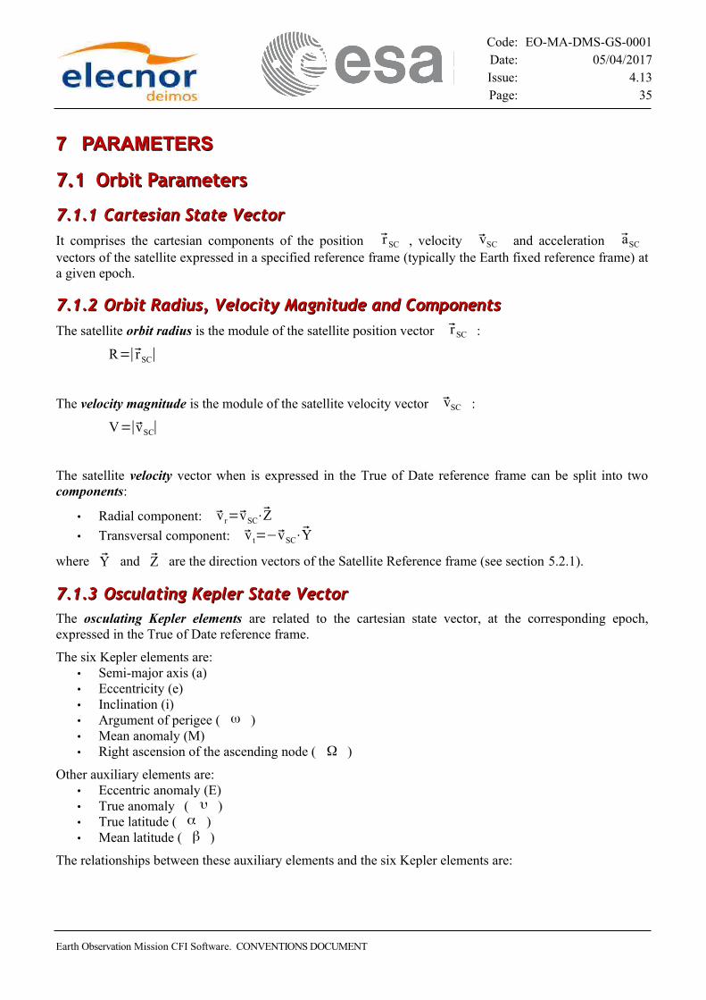
It comprises the cartesian components of the position r SC , velocity vSC and acceleration aSC vectors of the satellite expressed in a specified reference frame (typically the Earth fixed reference frame) at a given epoch.
7.1.27.1.2 Orbit Radius, Velocity Magnitude and Components Orbit Radius, Velocity Magnitude and Components
The satellite orbit radius is the module of the satellite position vector r SC :
R=∣r SC∣
The velocity magnitude is the module of the satellite velocity vector vSC :
V=∣vSC∣
The satellite velocity vector when is expressed in the True of Date reference frame can be split into two components:
• Radial component: vr=vSC⋅Z
• Transversal component: v t=−vSC⋅Y
where Y and Z are the direction vectors of the Satellite Reference frame (see section 5.2.1).
7.1.37.1.3 Osculating Kepler State Vector Osculating Kepler State VectorThe osculating Kepler elements are related to the cartesian state vector, at the corresponding epoch, expressed in the True of Date reference frame.
The six Kepler elements are:• Semi-major axis (a)• Eccentricity (e)• Inclination (i)• Argument of perigee ( ω )• Mean anomaly (M)• Right ascension of the ascending node ( Ω )
Other auxiliary elements are:• Eccentric anomaly (E)• True anomaly ( υ )• True latitude ( α )• Mean latitude ( β )
The relationships between these auxiliary elements and the six Kepler elements are:
Earth Observation Mission CFI Software. CONVENTIONS DOCUMENT

Code: EO-MA-DMS-GS-0001Date: 05/04/2017Issue: 4.13Page: 36
7.1.47.1.4 Mean Kepler State Vector Mean Kepler State VectorThe osculating six Kepler elements in the True of Date reference frame can be averaged with respect to the mean anomaly over 2π , to obtain the mean Kepler elements:
7.1.57.1.5 Equinoctial State Vector Equinoctial State VectorThe osculating Kepler elements are usually replaced by the equivalent osculating equinoctial elements for quasi-equatorial and quasi-circular orbits: • x1 = a • x2 = ex = e cos(W+w) • x3 = ey = e sin(W+w) • x4 = ix = +2 sin(i/2) sin(W) • x5 = iy = -2 sin(i/2) cos(W) • x6 = W + w + M
7.1.67.1.6 Ascending Node, Ascending Node Time, Nodal Period, Absolute Orbit Ascending Node, Ascending Node Time, Nodal Period, Absolute Orbit NumberNumber
The ascending node of an orbit is the intersection of that orbit, when the satellite goes from the southern to the northern hemisphere, with the x-y plane of the Earth fixed reference frame.
The ANX time is the UTC time of that ascending node.
The relative time with respect to the ANX time is the time elapsed since that ascending node till the current position within the orbit.
The nodal period of an orbit is the interval of time between two consecutive ascending nodes.
The Launch orbit from Kourou is regarded as absolute orbit number zero. From then on, each time a new ascending node is crossed the absolute orbit number is incremented by one.
Earth Observation Mission CFI Software. CONVENTIONS DOCUMENT

Code: EO-MA-DMS-GS-0001Date: 05/04/2017Issue: 4.13Page: 37
7.1.77.1.7 Mean Local Solar Time Drift Mean Local Solar Time DriftThe Mean Local Solar Time drift is the difference in angular velocity between the rate of change of the mean right ascension node and the motion of the mean Sun. This constant drift produces an increasing gap between the MLST of the ascending node and the angle measured from the line of nodes and the vernal equinox direction (see section 6.1.2). For a Sun-synchronous orbit, the MLST drift is zero.
The relationship between MLST of subsequent days is the following:
7.1.87.1.8 Repeat Cycle and Cycle Length Repeat Cycle and Cycle LengthIn the geo/helio-synchronous orbits, the ground track repeats precisely after a constant integer number of orbits and a constant duration. The duration in days of that period is called the repeat cycle, whereas the corresponding number of orbits is called the cycle length.
The repeat cycle of a Sun-synchronous orbit is an integer number of days, while it is not an integer number when considering a non Sun-synchronous orbit. Thus, the orbit information contained within a scenario file comprises an integer repeat cycle plus a drift on it, to cope with non Sun-synchronous orbits. The true repeat cycle shall result from the following:
7.1.97.1.9 Sub-satellite Point, Satellite Nadir and Ground Track Sub-satellite Point, Satellite Nadir and Ground TrackThe subsatellite point (SSP) is the normal projection of the position of the satellite in the orbit on to the surface of the Earth´s Reference Ellipsoid. It is also referred as nadir.
The trace made by the subsatellite point on the surface of the Earth’s Reference Ellipsoid due to the motion of the satellite along its orbit is called the ground track.
7.1.107.1.10 Mean Local Solar Time and True Local Solar Time Mean Local Solar Time and True Local Solar Time
7.1.10.1 Mean Local Solar Time
The Mean Local Solar Time (MLST) is the difference between the right ascension of the selected point in the orbit RA and the mean longitude of the Sun L, expressed in hours.
MLST= RA−L242
[hours]
The mean longitude L of the Sun represents the motion of the mean Sun and is given, in the Mean of Date reference frame, by (FLANDERN reference):
L = 280.46592 + 0.9856473516(t - 0.5) [deg]
Earth Observation Mission CFI Software. CONVENTIONS DOCUMENT
Code: EO-MA-DMS-GS-0001Date: 05/04/2017Issue: 4.13Page: 38
where t is the UT1 time expressed in the MJD2000 format.
The motion of the mean Sun has a constant mean longitude rate, namely L = 0.9856473516 [deg/s].
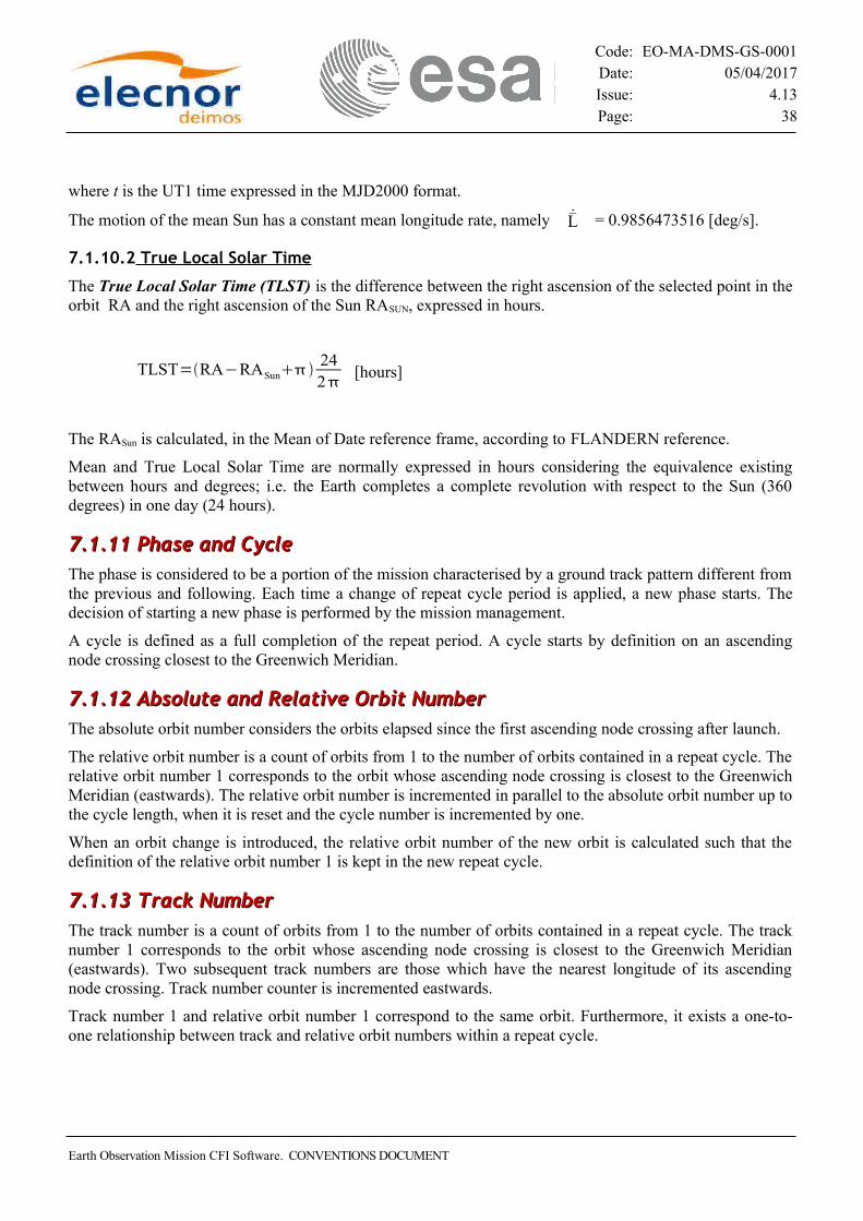
7.1.10.2 True Local Solar Time
The True Local Solar Time (TLST) is the difference between the right ascension of the selected point in the orbit RA and the right ascension of the Sun RASUN, expressed in hours.
TLST=RA−RASun242
[hours]
The RASun is calculated, in the Mean of Date reference frame, according to FLANDERN reference.
Mean and True Local Solar Time are normally expressed in hours considering the equivalence existing between hours and degrees; i.e. the Earth completes a complete revolution with respect to the Sun (360 degrees) in one day (24 hours).
7.1.117.1.11 Phase and Cycle Phase and CycleThe phase is considered to be a portion of the mission characterised by a ground track pattern different from the previous and following. Each time a change of repeat cycle period is applied, a new phase starts. The decision of starting a new phase is performed by the mission management.
A cycle is defined as a full completion of the repeat period. A cycle starts by definition on an ascending node crossing closest to the Greenwich Meridian.
7.1.127.1.12 Absolute and Relative Orbit Number Absolute and Relative Orbit NumberThe absolute orbit number considers the orbits elapsed since the first ascending node crossing after launch.
The relative orbit number is a count of orbits from 1 to the number of orbits contained in a repeat cycle. The relative orbit number 1 corresponds to the orbit whose ascending node crossing is closest to the Greenwich Meridian (eastwards). The relative orbit number is incremented in parallel to the absolute orbit number up to the cycle length, when it is reset and the cycle number is incremented by one.
When an orbit change is introduced, the relative orbit number of the new orbit is calculated such that the definition of the relative orbit number 1 is kept in the new repeat cycle.
7.1.137.1.13 Track Number Track NumberThe track number is a count of orbits from 1 to the number of orbits contained in a repeat cycle. The track number 1 corresponds to the orbit whose ascending node crossing is closest to the Greenwich Meridian (eastwards). Two subsequent track numbers are those which have the nearest longitude of its ascending node crossing. Track number counter is incremented eastwards.
Track number 1 and relative orbit number 1 correspond to the same orbit. Furthermore, it exists a one-to- one relationship between track and relative orbit numbers within a repeat cycle.
Earth Observation Mission CFI Software. CONVENTIONS DOCUMENT

Code: EO-MA-DMS-GS-0001Date: 05/04/2017Issue: 4.13Page: 39
7.1.147.1.14 Spacecraft Midnight Spacecraft MidnightThe Spacecraft Midnight (SMX) is the time just halfway the nadir day → night transition and the nadir night → day transition. Such transitions are times at which the Sun Zenith Angle (SZA, angle satellite-nadir-sun) is 90 deg. In the day → night transition, the SZA is increasing (i.e. there is a transition from SZA<90 to SZA>90). In the night → day transition the SZA is decreasing (i.e. there is a transition from SZA>90 to SZA<90).
7.27.2 Attitude Coordinate Systems Parameters Attitude Coordinate Systems Parameters
7.2.17.2.1Attitude determination parametersAttitude determination parametersThere are different ways for providing the attitude parameters in order to establish the transformations between the satellite reference frames:
1. Attitude Mispointing Angles:
The transformation from one satellite reference frame to another is accomplished by three consecutive rotations over the angles pitch h, roll x and yaw z according to the Euler convention defined in section 7.7.
The time derivative of those angles are the pitch, roll and yaw rates.
Both those angles and their rates are a function of the selected attitude control mode (see attitude control section particular to each satellite).
Usually these angles are used for transforming from the satellite orbital frame to the satellite nominal attitude frame. Frequently there are superimposed on them a set of mispointing angles that make the Satellite Nominal Attitude Reference frame transform to the Satellite Attitude Reference frame.
The mispointing angles are expressed as three components, namely pitch Dh, roll Dx, and yaw Dz.
The time derivative of those mispointing angles are the mispointing rates.
2. Attitude Quaternions:
The previous transformations could be given via quaternions (also called Euler symmetric parameters) instead of angles.
Quaternions are base on Euler’s theorem that given two coordinate systems, there is one invariant axis (e) along which measurements are the same in both coordinate systems and that is possible to move from one system to the other through a rotation (b) about the axis e. According to this theorem, the quaternions is defined as:
Earth Observation Mission CFI Software. CONVENTIONS DOCUMENT

Code: EO-MA-DMS-GS-0001Date: 05/04/2017Issue: 4.13Page: 40
A rotation matrix (direction cosine matrix) can be expressed in term of the quaternion parameters as follows:
There are for possible solutions for getting the quaternion from the rotation matrix:
The EOCFI returns the weighted mean of the four possible solutions (with q4 as real part of the quaternion):
3. AOCS Rotation Amplitudes
The AOCS rotation amplitudes are the three constants Cx, Cy and Cz that define the transformation from the Satellite Nominal Attitude to the Satellite Attitude Reference frame according to the selected attitude control mode (see attitude control section particular to each satellite).
Earth Observation Mission CFI Software. CONVENTIONS DOCUMENT

Code: EO-MA-DMS-GS-0001Date: 05/04/2017Issue: 4.13Page: 41
7.2.27.2.2 Satellite Centered Direction Satellite Centered DirectionThe parameters that define a direction in a Satellite Reference frame are the satellite related azimuth and the satellite related elevation. If x, y, z are the axis in the Satellite Reference frame, the azimuth and elevation are defined in the following way (check Figure 12):
• Azimuth: the angle in the xy plane from -y axis to the projection of the pointing direction in the xy plane; the angle direction is taken from -y axis to -x axis.
• Elevation: the angle from the projection of the pointing direction in the xy plane to the pointing direction itself, measured from xy plane to -z axis.
Figure 12: Azimuth and elevation definition
7.37.3 Earth-related ParametersEarth-related ParametersNote that altitude refers always to geodetic altitude except when the contrary is explicitly said.
7.3.17.3.1 Geodetic Position Geodetic PositionThe geodetic coordinates of a point, related to the Earth´s Reference Ellipsoid, are the geocentric longitude l, geodetic latitude j, and geodetic altitude h, represented in Figure 13.
The geocentric latitude j’, geocentric radius r and the geocentric distance d are also represented in Figure13 .
The parameters a, e and f, i.e. the semi-major axis, the first eccentricity and the flattening of the Earth’s Reference Ellipsoid (see section 8.2.2), define the equations that express these other parameters.
Earth Observation Mission CFI Software. CONVENTIONS DOCUMENT

Code: EO-MA-DMS-GS-0001Date: 05/04/2017Issue: 4.13Page: 42
The geocentric latitude j’ and the geodetic latitude j are related by the expression:
tan =1
1−f 2
tan '
The geocentric radius r is calculated with:
=a 1−e2
1−e2 cos2 '
The relationship between the cartesian coordinates of a point and its geodetic coordinates is:
x= Nh cos cos
x=Nh cos sin
x=[1−e2 Nh ]sin
where N is the East-West radius of curvature:
N=a
1−e2sin 2
The inverse transformation, from the cartesian to the geodetic coordinates, cannot be performed analytically. The iterative method that will be used will be initialized according to (BOWRING reference).
The normal projection of a point on the surface of the Earth’s Reference Ellipsoid is called Nadir, and when that point corresponds to the position of the satellite, the projection is called subsatellite point.
Another important radius of curvature is M, the North-South radius of curvature:
Earth Observation Mission CFI Software. CONVENTIONS DOCUMENT
Figure 13: Geodetic position

Code: EO-MA-DMS-GS-0001Date: 05/04/2017Issue: 4.13Page: 43
M=a 1−e2
1−e2sin2
3
The radius of curvature in any selected direction RAz can be calculated with the expression:
1RAz
=cos2Az
M
sin2 Az
N
where Az is the angle of the selected direction expressed in the Topocentric reference frame.
The satellite centred aspect angle as/c is the angle measured at the satellite between the geometric direction5 from the satellite to the subsatellite point and the geometric direction from the satellite to the centre of the Earth.
The geocentric aspect angle ag is the angle measured at the centre of the Earth between the geometric direction from the Earth centre to the subsatellite point and the geometric direction from the Earth centre to the satellite.
The subsatellite point centred aspect angle assp is the angle measured at the subsatellite point between the geometric direction from the subsatellite point to the satellite and the geometric direction from the subsatellite point to the centre of the Earth.
The geodesic distance or ground range between two points that lay on an ellipsoid is by definition the minimum distance between those two points measured over that ellipsoid.
The velocity vE and aE acceleration relative to the Earth, i.e the Earth’s Reference Ellipsoid, of a point that lays on its surface can be split into different components.
• Northward component = vE⋅N or aE⋅N
• Eastward component = vE⋅E or aE⋅E• Ground track tangential component = vE⋅t=vE or aE⋅t• Magnitude = vE=∣vE∣ or aE=∣aE∣
• Azimuth = the azimuth of the vE and aE vectors measured in the Topocentric reference frame
where N and E are the north and east direction axes of the Topocentric reference frame centred on that point, and t is the unitary vector tangent to the ground track at that point.
5 The geometric direction is defined by the straight line that connects the initial and the final point.
Earth Observation Mission CFI Software. CONVENTIONS DOCUMENT

Code: EO-MA-DMS-GS-0001Date: 05/04/2017Issue: 4.13Page: 44
7.3.27.3.2 Earth Centered Direction Earth Centered DirectionThe parameters that define a direction from the centre of the Earth to a point in the Mean of Date reference frame are the right ascension (α) and the declination (δ) , shown in next figure:
7.3.37.3.3 Topocentric Direction Topocentric DirectionThe parameters that define a direction in the Topocentric reference frame are the topocentric azimuth (Az) and the topocentric elevation (El), represented in the next drawing:
7.47.4 Ground Station Parameters Ground Station Parameters
7.4.17.4.1 Ground Station Location Ground Station Location
The location of a Ground Station is defined by its geodetic parameters: i.e. geocentric longitude l, geodetic latitude j, and geodetic altitude h with respect to the Earth’s Reference Ellipsoid.
Earth Observation Mission CFI Software. CONVENTIONS DOCUMENT
Figure 15: Topocentric direction
Figure 14: Earth centred direction

Code: EO-MA-DMS-GS-0001Date: 05/04/2017Issue: 4.13Page: 45
7.4.27.4.2 Ground Station Visibility Ground Station VisibilityThe visibility of a point from a Ground Station is limited by the minimum link elevation at which that point must be in order for the link between that Ground Station and that point to be established.
That minimum topocentric elevation is expressed in the Topocentric reference frame centred at that Ground Station (see section 7.3.3), and although it is ideally a constant, in fact a real Ground Station usually has a physical mask that makes the minimum topocentric elevation be a function of the topocentric azimuth.
7.57.5 Target Parameters Target Parameters
7.5.17.5.1 Moving and Earth-fixed Targets Moving and Earth-fixed Targets
A target r t is a point that is observed from the satellite and that satisfies certain conditions.
The look direction, or line of sight (LOS), u0 is the light direction, at the satellite, of the path followed by the light in its travel from the target to the satellite.
If the target moves with respect to the Earth, as a result of a change in the satellite position or a change in the look direction, it is called the moving target.
If the target is fixed with respect to the Earth, which implies that if the satellite position changes then the look direction has to change in the precise way to keep looking to that particular point fixed to the Earth, it is called the Earth fixed target.
In other words, the velocity of the moving target is the result of the motion of the satellite and the change in the look direction, or in the conditions that define it, with time. On the other hand, the velocity of the Earth fixed target is only a function of the position of that point with respect to the Earth’s Reference Ellipsoid and the rotation of the Earth fixed reference frame.
7.5.27.5.2 Location Parameters Location Parameters
The location of a target is defined by its geodetic parameters: i.e. geocentric longitude l, geodetic latitude j, and geodetic altitude h with respect to the Earth’s Reference Ellipsoid, although it also can be defined by its cartesian position vector (x, y, z) expressed in the Earth fixed reference frame.
7.67.6 Sun and Moon Parameters Sun and Moon ParametersThe Sun semi-diameter DSun is the apparent semi-diameter of the Sun, expressed in radians, as seen from the satellite, and is calculated with the equation:
DSun=dSun
RSun−SC
where dSun = 6.96 x 10⁸ [m] is the semi-diameter of the Sun, and RSun-S/C is the geometric distance between the satellite and the Sun centre.
The Moon semi-diameter DMoon is the apparent semi-diameter of the Moon, expressed in degrees, as seen from the satellite, and is calculated with the equation:
Earth Observation Mission CFI Software. CONVENTIONS DOCUMENT

Code: EO-MA-DMS-GS-0001Date: 05/04/2017Issue: 4.13Page: 46
DMoon=d Moon
RMoon−SC
where dMoon = 1738000 [m] is the semi-diameter of the Moon, and RMoon-S/C is the geometric distance between the satellite and the Moon centre.
The area of the Moon lit by the Sun AMoon-Sun is calculated with the expression:
AMoon−Sun=1cos Sun−Moon−SC
2
where qSun-Moon-S/C is the angle measured at the centre of the Moon between the geometric direction from the centre of the Moon to the centre of the Sun and the geometric direction from the centre of the Moon to the satellite.
If AMoon-Sun = 0 it is a new Moon, and if AMoon-Sun = 1 it is a full Moon
The satellite eclipse flag indicates whether or not the path followed by the light from the centre of the Sun to the satellite intersects the Earth´s Reference Ellipsoid. It is equivalent to the satellite to Sun visibility flag.
The satellite to Moon visibility flag indicates whether or not the path followed by the light from the centre of the Moon to the satellite intersects the Earth´s Reference Ellipsoid.
The target to Sun visibility flag indicates whether or not the path followed by the light from the centre of the Sun to the target intersects the Earth´s Reference Ellipsoid.
7.77.7 Euler angles Euler anglesThe Earth Observation CFI applies the following convention when using Euler angles to rotate one reference frame to another.
The rotated reference frame (X’s, Y’s, Z’s) is obtained by applying three consecutive rotations to the original reference frame: 1. Rotation around -Ys over a roll angle h 2. Rotation around -X1s (i.e the rotated Xs) over a pitch angle x 3. Rotation around +Z2s (i.e the rotated Z1s) over a yaw angle z.
Next drawing depicts the three rotations:
Earth Observation Mission CFI Software. CONVENTIONS DOCUMENT

Code: EO-MA-DMS-GS-0001Date: 05/04/2017Issue: 4.13Page: 47
Earth Observation Mission CFI Software. CONVENTIONS DOCUMENT
Figure 16: Euler Angles
Xs
Ys
Zs
X1 s
Z2 s
Y1 s
Z1 s
Y2 s
Z1 s
X1 s
Y2 s
Z2 s = Z’s
X2 sY’s
X’s

Code: EO-MA-DMS-GS-0001Date: 05/04/2017Issue: 4.13Page: 48
88 MODELSMODELS
8.18.1 Attitude Modes Attitude ModesThe Earth Observation CFI Software supports the following three axes stabilized Attitude Modes:
• Generic Pointing Mode (GPM);• Yaw Steering Mode (YSM);• Local Normal Pointing (LNP);• Zero-Doppler Pointing (ZDOP);• Geocentric Pointing (GP).
The GPM allows the user to define the Satellite Nominal Reference Frame (SNRF, see section 5.2) in the most generic way by selecting:
• The PRIMARY axis and direction (+/-X, +/-Y, +/- Z);• The PRIMARY axis target (see list below);• The SECONDARY axis and direction (+/-X, +/-Y, +/- Z, different from primary axis);• The SECONDARY axis target (see list below).
The SNRF is defined as follows:• The primary axis (with direction) is aligned to the primary axis target;• The secondary axis (with direction) is aligned to the vector obtained by computing the cross-product
between primary axis (positive direction) and the secondary target axis;• The tertiary axis completes the right-hand frame together with primary and secondary axes.
For example, with reference to Table XX, SNRF in Yaw Steering mode is calculated as follows:• The negative Z axis is aligned with the satellite position vector in the Earth Fixed reference system;• The positive X axis is aligned with the cross product of Z axis and the velocity in the Earth Fixed
reference system;• Y axis is computed according to right-hand rule.
There are many possible choices in the definition of the axis target, for example:• Sun pointing • Moon pointing • Earth pointing • Nadir pointing • Inertial velocity pointing • Earth Fixed velocity pointing • Inertial target pointing• Earth Fixed target pointing• Earth Fixed Satellite position
YSM, GP, LNP and ZDOP modes are special cases of Generic Pointing Modes, with axes and targets that are predefined according to the following table:
Table 4: Attitude control modes
Attitude Primary Primary Uffish thought
Secondary Secondary Axis
Earth Observation Mission CFI Software. CONVENTIONS DOCUMENT

Code: EO-MA-DMS-GS-0001Date: 05/04/2017Issue: 4.13Page: 49
Mode Axis Target Axis Target
YSM -Z Nadir +X EF Velociy
ZDOP -Y EF Velocity -X Nadir
LNP -Z Nadir +X Inertial Velocity
GP Z EF Satellite Position
+X Inertial Velocity
The current Satellite Reference Frame (SRF) can be modeled in several ways by the user, for example:• with three consecutive rotations of the SNRF over three user-defined angles (mispointing angles);• with a user-provided misalignment matrix between SNRF and SRF;• modulating the misalignment angles with biases and harmonics (provided by the user);• reading attitude angles from a file.
8.28.2 Earth Earth
8.2.18.2.1 Earth Position Earth PositionThe position and velocity of the Earth in the Barycentric and Heliocentric Mean of 2000 reference frames will be calculated according to FLANDERN reference.
8.2.28.2.2 Earth Geometry Earth GeometryThe geometry of the Earth is modeled by a Reference Ellipsoid. Different definitions of reference ellipsoids can be found hereafter in Table 5 .
Table 5: WGS84 parameters
Parameter Notation WGS 84
Semi major axis (m) a 6378137
Flattening = (a-b)/a f 1/298.257223563
First Eccentricity = (a2 - b2)/a2 e 0.0818191908426
Semi minor axis (m) b 6356752.3142
The minimum distance between two points located on an ellipsoid is the length of the geodesic that crosses those two points. This geodesic distance will be calculated according to HEISKANEN reference.
The surface at a certain geodetic altitude h over the Earth’s Reference Ellipsoid is defined by:
x= Nh cos cos
x=Nh cos sin
Earth Observation Mission CFI Software. CONVENTIONS DOCUMENT

Code: EO-MA-DMS-GS-0001Date: 05/04/2017Issue: 4.13Page: 50
x=[1−e2 Nh ]sin
where N is the radius of curvature parallel to the meridian:
N=a
1−e2sin 2
and j and l are the geodetic latitude and geocentric longitude of a point on that ellipsoid.
Nevertheless, the surface at a certain geodetic altitude h over the Earth´s Reference Ellipsoid will be modelled as another ellipsoid, concentric with it, and with (a+h) and (b+h) as semi-major and semi-minor axis.
This simplification is quite accurate and have the advantage that allows the analytical calculation of the intersection or tangent points with such a surface.
8.2.38.2.3 Earth Atmosphere Earth AtmosphereThe Earth atmosphere can be represented by different models. The selection of a certain atmosphere model depends upon the requirements imposed by the mission definition. It could include certain simplifications to the generic definition.
It is also assumed that the atmosphere rotates with the same angular velocity as the Earth.
The definition of the Earth atmosphere is important for instrument pointing task and refraction.
8.2.3.1 US Standard Atmosphere 1976
The U.S Standard Atmosphere 1976 Atmosphere model is modified as follows:• it ranges from Z = 0 Km to Z = 86 Km.• the ratio M/M0 decreases linearly from Z = 80 to Z = 86 Km.• the linear relationship between TM and H is replaced by either an arc of a circle or by a polynomial
function in the vicinity of the points where the molecular-scale temperature gradient changes, in order to have a continuous and differentiable function TM = f(H)
The U.S Standard Atmosphere 1976 is defined as follows (STD76 reference):• The air is assumed to be dry, and at altitudes sufficiently below 86 Km, the atmosphere is assumed
to be homogeneously mixed with a relative-volume composition leading to a constant mean molecular weight M.
• The air is treated as if it were a perfect gas, and the total pressure P, temperature T, and total density r at any point in the atmosphere are related by the equation of state, i.e. the perfect gas law, one form of which is:
P=R T
M
where R = 8.31432 x 10³ [Nm/(KmolK)] is the universal gas constant.
Earth Observation Mission CFI Software. CONVENTIONS DOCUMENT

Code: EO-MA-DMS-GS-0001Date: 05/04/2017Issue: 4.13Page: 51
• Besides the atmosphere is assumed to be in hydrostatic equilibrium, and to be horizontally stratified so that dP, the differential of pressure, is related to dZ, the differential of geometric altitude, by the relationship:
dP=−gdZ
where g is the altitude-dependent acceleration of gravity, which can be calculated with the expression:
g=g0r 0
r 0Z
2
where r0 = 6356766 [m] and g0 = 9.80665 [m/s2], and that yields:
H=r0 Z
r0Z
where H is the geopotential altitude.• The molecular-scale temperature TM at a point is defined as:
TM=TM0
M
where M0 = 28.9644 [Kg/Kmol] is the sea-level value of M.
In the region from Z = 0 Km to Z = 80 Km M is constant and M = M0, whereas between Z = 80 Km and Z = 86 Km, the ratio M/M0 is assumed to decrease from 1.000000 to 0.999578
Up to altitudes up to 86 Km the function TM versus H is expressed as a series of seven successive linear equations. The general form of these linear equations is:
TM=TM, bLM, bH−H0
The value of TM,b for the first layer (b = 0) is 288.15 [K], identical to T0 the sea-level value of T.
The six values of Hb and LM,b are:
Table 6: Molecular-scale temperature coefficients
Subscript Geopotential altitude Hb [Km]Molecular-scale temperature
gradient LM,b [K/Km]
0 0 -6.5
1 11 0.0
2 20 1.0
3 32 2.8
4 47 0.0
Earth Observation Mission CFI Software. CONVENTIONS DOCUMENT
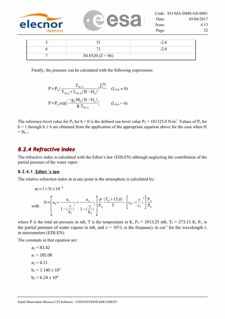
Code: EO-MA-DMS-GS-0001Date: 05/04/2017Issue: 4.13Page: 52
5 51 -2.8
6 71 -2.0
7 84.8520 (Z = 86)
Finally, the pressure can be calculated with the following expressions:
P=PbTM , b
TM, bLM , bH−Hb
g0 M0
R LM ,b (LM,b 0)
P=Pb exp[−g0 M0 H−Hb
R TM , b
] (LM,b = 0)
The reference-level value for Pb for b = 0 is the defined sea-level value P0 = 101325.0 N/m2. Values of Pb for b = 1 through b 6 are obtained from the application of the appropriate equation above for the case when H = Hb+1.
8.2.48.2.4 Refractive index Refractive indexThe refractive index is calculated with the Edlen’s law (EDLEN) although neglecting the contribution of the partial pressure of the water vapor.
8.2.4.1 Edlen´s law
The relative refraction index m at any point in the atmosphere is calculated by:
m=1N×10−6
with N=[a0
a1
1−
b1
2
a2
1−
b2
2 ]
PP0
T015,0
T−[c0−
c1
2
] Pw
P0
where P is the total air pressure in mb, T is the temperature in K, P 0 = 1013.25 mb, T0 = 273.15 K, Pw is the partial pressure of water vapour in mb, and n = 104/l is the frequency in cm-1 for the wavelength l in micrometers (EDLEN)
The constants in that equation are:
a0 = 83.42
a1 = 185.08
a2 = 4.11
b1 = 1.140 x 10⁵
b2 = 6.24 x 10⁴
Earth Observation Mission CFI Software. CONVENTIONS DOCUMENT

Code: EO-MA-DMS-GS-0001Date: 05/04/2017Issue: 4.13Page: 53
c0 = 43.49
c1 = 1.70 x 10⁴
The total air pressure and the temperature will be the corresponding to the atmosphere previously described, and the term in the last equation that corresponds to the partial pressure of water vapor will be neglected and therefore not calculated.
8.2.58.2.5 Digital Elevation Models (DEM) Digital Elevation Models (DEM)The digital elevation model of the Earth consists in a set of points defining a grid for which a measure of the altitude over the Earth reference ellipsoid is given.
The following DEM types are supported:
• GETASSE30 (versions 1,2,3), see http://earth.esa.int/services/amorgos/download/getasse/
• ACE2, see http://tethys.eaprs.cse.dmu.ac.uk/ACE2/shared/overview
• ASTER GDEM, see http://asterweb.jpl.nasa.gov/gdem.asp
GETASSE30 and ACE2 DEM can be downloaded also from this URL:
http://eop-cfi.esa.int/index.php/mission-cfi-software/eocfi-software/support-files (registration required)
8.38.3 Sun and Moon Sun and MoonSun and Moon position and velocity in the True of Date reference frame will be calculated according to FLANDERN reference.
8.48.4 Stars StarsTo calculate the look direction from the satellite to a star, two consecutive steps must be performed:
• To calculate the stars coordinates in the Mean of Date reference frame at the current epoch, taking as input a star catalogue (assumed to be expressed in the Barycentric Mean of 2000.0 reference frame for the epoch J2000.0).
• To calculate the star coordinates in the Satellite Relative Actual Reference frame at the same epoch.
The first step must apply the following corrections:
Table 7: First step correction of star looking direction
Correction Description Effect
Earth Observation Mission CFI Software. CONVENTIONS DOCUMENT

Code: EO-MA-DMS-GS-0001Date: 05/04/2017Issue: 4.13Page: 54
Proper motion Intrinsic motion of the star across thebackground with respect to a reference epoch (e.g J2000.0) leading to a change in the apparent star position at the current epoch
Lower than 0.3 mdeg/year
Annual parallax Apparent displacement of the position ofthe star caused by the difference in the position of the barycenter and the position of the Earth with the motion of the Earth around the Sun during the year
Lower than 0.3 mdeg
Light deflection Gravitational lens effect of the Sun Lower than 500 mdeg at thelimb of the Sun and falling off rapidly with distance, e.g. to 6mdeg at an elongation of 20 deg(so it will be ignore d )
Annual aberration Apparent displacement of the position ofthe star caused by the finite speed of light combined with the motion of the Earth around the Sun during the year
Lower than 6 mdeg
Precession Change of the position of the star causedby the transformation from the Geocentric Mean of 2000.0 to the Mean of Date reference frame
Lower than 6.0 mdeg/year
whereas the second step must apply the following ones:
Table 8: Second step corrections of star looking direction
Correction Description Effect
Satellite parallax Apparent displacement of the position ofthe star caused by the difference in the position of the satellite and the position of the Earth with the motion of the satellite around the Earth during an orbit
Lower than 0.015 mdeg even forthe closest stars (so it will be ign o red)
Satellite aberration Apparent displacement of the position ofthe star caused by the finite speed of light combined with the motion of the satellite around the Earth during an orbit
Lower than 1 mdeg for LEOspacecraft
8.4.18.4.1 Stars Positions Stars PositionsTo apply some of the necessary corrections to calculate the coordinates of a star in the Satellite Relative Actual Reference frame, the following expressions shall be used (ALMAN95 reference):
• Get the following variables from a star catalogue:
Earth Observation Mission CFI Software. CONVENTIONS DOCUMENT

Code: EO-MA-DMS-GS-0001Date: 05/04/2017Issue: 4.13Page: 55
− Right ascension at J2000.0 expressed in the Barycentric Mean of 2000.0: a0 [rad]− Declination at J2000.0 expressed in the Barycentric Mean of 2000.0: d0 [rad]− Proper motion in the right ascension: ma [rad/century]− Proper motion in the declination: md [rad/century]− Radial velocity: n [au/century]− Parallax: p [rad]
• Correct the star position obtained from the star catalogue (a0, d0) for the proper motion and annual parallax effects using the expressions:
where T = (t - 0.5)/36525, and t is the current TDT expressed in the MJD2000 format, and r B, Earth is the position of the Earth in AU at that TDT, expressed in the Barycentric Mean of 2000
reference frame.• Correct the star position for the annual aberration effect, using the following expressions:
where vB,Earth is the velocity of the Earth in AU/d at the current TDT expressed in the Barycentric Mean of 2000 reference frame.
• The satellite aberration can be calculated with the expression (IERS_SUPL reference):
=asin vc
sin −14
vc
2
sin2 [rad]
Earth Observation Mission CFI Software. CONVENTIONS DOCUMENT

Code: EO-MA-DMS-GS-0001Date: 05/04/2017Issue: 4.13Page: 56
where Dq is the change in the look direction from the satellite to the star, v is the velocity of the satellite expressed in the True of Date reference frame, and c is the velocity of the light in a vacuum.
• The following drawing sketches the satellite aberration:
8.58.5 Ray tracingRay tracingThe path followed by the light when it crosses the Earth´s atmosphere is bent due to the effect of the atmospheric refraction, and therefore the direction of the light when it enters the atmosphere uE is different to the direction of the light when it leaves the atmosphere uL .
This effect is depicted in the following drawing:
Earth Observation Mission CFI Software. CONVENTIONS DOCUMENT
Figure 17: Satellite aberration

Code: EO-MA-DMS-GS-0001Date: 05/04/2017Issue: 4.13Page: 57
Note that this drawing also represents the satellite position rSC , the tangent point of the light path over the Earth’s Reference Ellipsoid r T and the corresponding tangent altitude hT, the maximum angular deviation of the light path at the entrance qE and at the exit qL of the atmosphere, where:
cosE=cos L= uE · uL
The geometric distance RT,g between the satellite position and the tangent point is defined as:
RT ,g=∣rT− rSC∣
Finally, the range ST is the actual distance between those two points measured along the path.
A ray tracing model calculates the path followed by the light from the satellite through the atmosphere to the observation target.
8.5.18.5.1No refraction modelNo refraction modelThis is the simplest model as the effect of the atmospheric refraction is not considered, therefore the path followed by the light is approximated by a straight line.
The advantage of this model is that is purely analytical.
8.5.28.5.2Refraction modelsRefraction modelsThere are two refraction ray tracing models, both based on the three following assumptions:
Earth Observation Mission CFI Software. CONVENTIONS DOCUMENT
Figure 18: Ray path
hT
uL
uE
rS/C
rT
Earth
Earth Atmosphere
L
rS/C = satellite position vectoruE = path direction before crossing the atmosphereuL = path direction after crossing the atmosphererT = tangent point position vectorhT = tangent altitudeE = path direction deviation before crossing the atmosphereL = path direction deviation after crossing the atmosphere
= uE
= uL E
Apparent path
Actual path
Direct pathparallelpaths

Code: EO-MA-DMS-GS-0001Date: 05/04/2017Issue: 4.13Page: 58
• The relative refractive index is a function only of the geometric altitude H above the Earth´s Reference Ellipsoid, i.e. the Earth’s atmosphere model is based on the assumption that the longitude or latitude variations of the relative refraction index are negligible
• The surface at a certain geometric altitude H will be modeled as an ellipsoid, concentric with the Earth’s Reference Ellipsoid, with (a+H) and (b+H) as semi-major and semi-minor axis.
• The light path lays in a plane: this plane is defined by the satellite position vector rSC , and by the known light direction, either uE or uL . This assumption implies that the three dimensional effects of the light path bending are assumed to be negligible.
This simplification is quite accurate and has the advantage to allow the analytical calculation of the intersection of tangent points with such a surface.
The light path is calculated by integrating the differential Eikonal´s equation in that plane:
dds
ndds
r =∇ m
where r is the position vector of a point in the light path, s is the arc length along that path, and m is the relative refraction index.
Note that iterative methods are usually needed to implement a refraction ray tracing model.
8.5.2.1 Standard atmosphere model
This refraction ray tracing model is based on the atmosphere model described in section 8.2.3.
8.5.2.2 User’s atmosphere model
In this case the atmosphere model is based on a file supplied by the user, which defines the relative refraction index m at a discrete set of geometric altitudes H.
To have a continuous, and differentiable, relationship between the relative refraction index and the geometric altitude, the relative refraction index at any geometric altitude will be calculated by means of a cubic spline based on the two closest pair of data supplied by the user.
8.5.38.5.3 Predefined refraction corrective functions model Predefined refraction corrective functions modelThis model also assumes that the light path lays in a plane, i.e. the reference plane defined by the satellite position vector rSC , and by the known light direction, either uE or uL .
It is based on the calculation of the parameters hT, RT,g, and ST of the tangent point using the no refraction ray tracing model, and the calculation of a set of refraction corrective terms by means of predefined curves that depend only on the tangent altitude hT and the wavelength of the light signal l.
Those corrective terms are:
hT=f1 hT ,
RT,g=f2hT ,
E= L=f3h t ,
ST=f4 hT ,
Earth Observation Mission CFI Software. CONVENTIONS DOCUMENT

Code: EO-MA-DMS-GS-0001Date: 05/04/2017Issue: 4.13Page: 59
The tangent point, corrected for the effects of the atmosphere refraction, is calculated knowing that it lays in the reference plane, that the tangent altitude is hT + DhT, and that the geometric distance from the satellite to the tangent point is RT,g + DRT,g
The actual length of the light path is calculated as ST + DST
The light direction at the entrance or at the exit of the atmosphere, is calculated knowing that it lays in that reference plane, and that is deviated by an angle DqE = DqL.
The great advantage of this ray tracing model is that it is relatively quite accurate and is much faster than the refraction ray tracing models as it can be calculated analytically.
Earth Observation Mission CFI Software. CONVENTIONS DOCUMENT

Code: EO-MA-DMS-GS-0001Date: 05/04/2017Issue: 4.13Page: 60
99 UNITSUNITS
In general, the units that will be used in all the CFI software will be the SI units, except for the angle that will use the degree instead of the radian.
Table 9: Units in CFI Software
Quantity Unit Symbol
Length meter m
Mass kilogram kg
Time second s
Thermodynamic temperature kelvin K
Amount of substance mole mol
Plane angle degree deg
Frequency hertz Hz
Pressure pascal Pa
Earth Observation Mission CFI Software. CONVENTIONS DOCUMENT


![[ 1 ] - CFI](https://img.pdfslide.net/doc/110x75/62745ab3b8755b501d68081b/-1-cfi.jpg)