Embed Size (px)
Citation preview
© 2019 WishBone Medical, Inc.
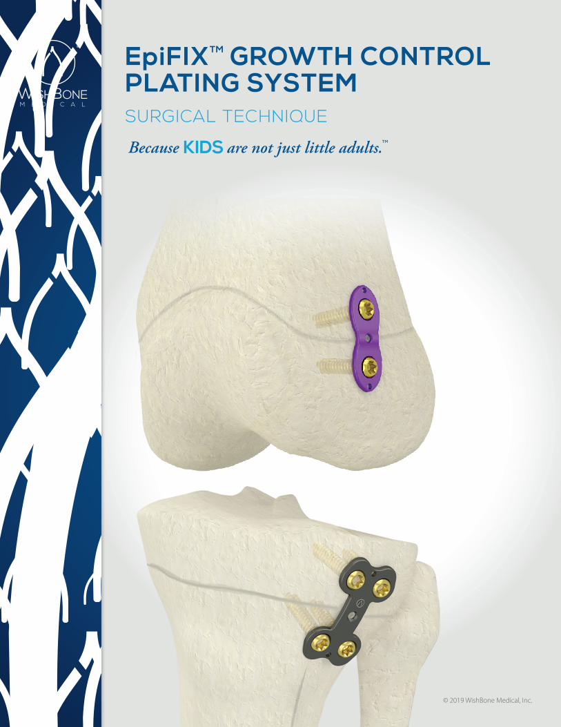
EpiFIXTM GROWTH CONTROL PLATING SYSTEMSURGICAL TECHNIQUE
TM

TABLE OF CONTENTS
Introduction
System Overview .................................................................................................................................................................................. 3
Kit Components .......................................................................................................................................................................... 3
Plate Features .......................................................................................................................................................................... 4-5
Screws ................................................................................................................................................................................................ 6
Indications .............. ................................................................................................................................................................................... 6
Surgical Technique
Plate Sizing & Fixation ...........................................................................................................................................................................7
Guide Wire Insertion ..................................................................................................................................................................... 7-8
Screw Sizing .............................................................................................................................................................................................. 8
Screw Insertion ........................................................................................................................................................................................ 9
Final Control and Closure ................................................................................................................................................................. 10
Order Information
Curved 2-Hole EpiFIXTM Plate, 12mm Procedure Kits ......................................................................................................... 11
Curved 2-Hole EpiFIXTM Plate, 16mm Procedure Kits ......................................................................................................... 11
Curved 4-Hole EpiFIXTM Plate, 22mm Procedure Kits ....................................................................................................... 12
Curved 4-Hole EpiFIXTM Plate, 26mm Procedure Kits ....................................................................................................... 12
WISHBONE MEDICAL EpiFIXTM GROWTH CONTROL SURGICAL TECHNIQUE 3
Introduction
WISHBONE MEDICALEpiFIXTM GROWTH CONTROL PLATING SYSTEM
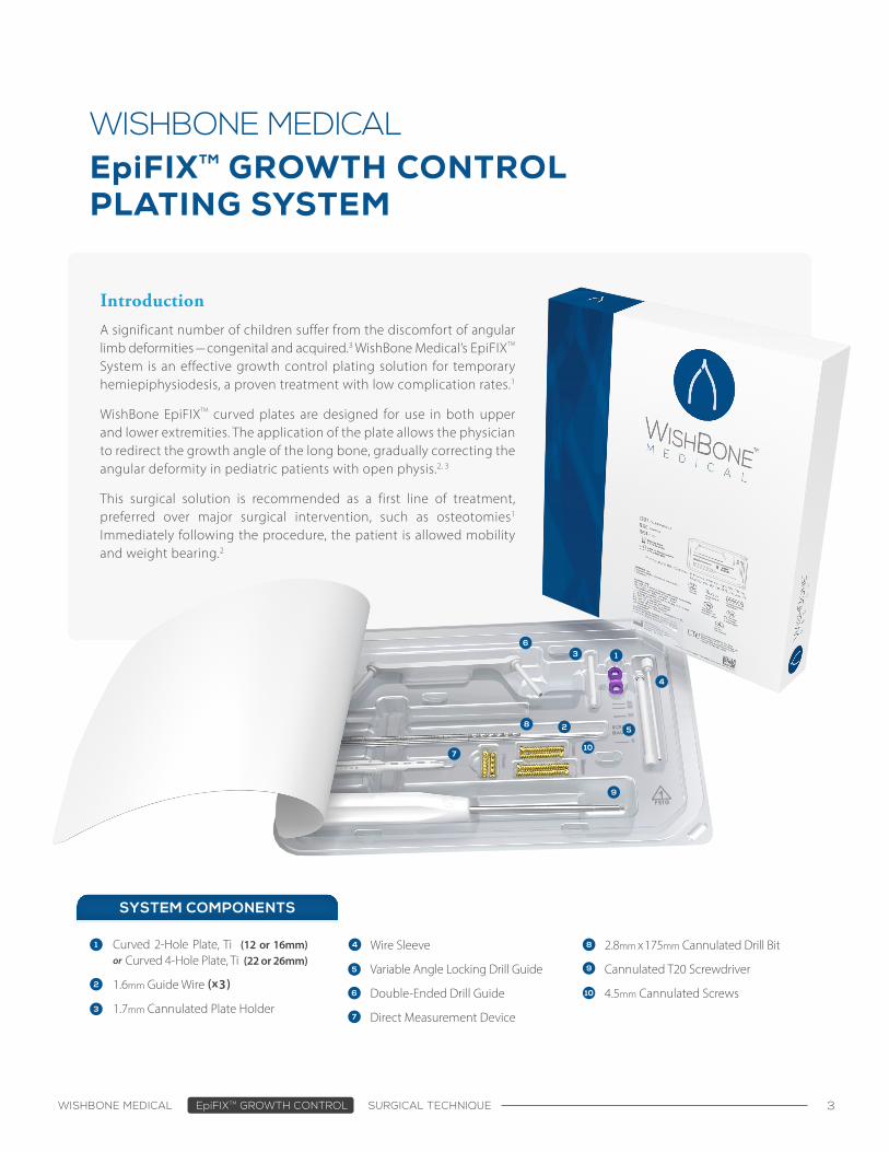
Curved 2-Hole Plate, Ti (12 or 16mm) or Curved 4-Hole Plate, Ti (22 or 26mm)
1.6mm Guide Wire (x3)
1.7mm Cannulated Plate Holder
SYSTEM COMPONENTS
Wire Sleeve
Variable Angle Locking Drill Guide
Double-Ended Drill Guide
Direct Measurement Device
2.8mm x 175mm Cannulated Drill Bit
Cannulated T20 Screwdriver
4.5mm Cannulated Screws
A significant number of children suffer from the discomfort of angular limb deformities — congenital and acquired.3 WishBone Medical’s EpiFIXTM System is an effective growth control plating solution for temporary hemiepiphysiodesis, a proven treatment with low complication rates.1
WishBone EpiFIXTM curved plates are designed for use in both upper and lower extremities. The application of the plate allows the physician to redirect the growth angle of the long bone, gradually correcting the angular deformity in pediatric patients with open physis.2, 3
This surgical solution is recommended as a first line of treatment, preferred over major surgical intervention, such as osteotomies1 Immediately following the procedure, the patient is allowed mobility and weight bearing.2
WISHBONE MEDICAL EpiFIXTM GROWTH CONTROL SURGICAL TECHNIQUE 4
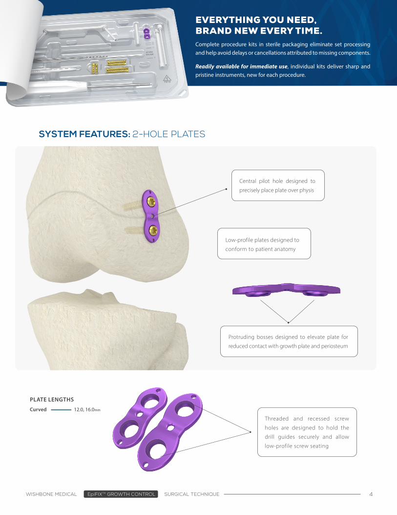
SYSTEM FEATURES: 2-HOLE PLATES
Protruding bosses designed to elevate plate for
reduced contact with growth plate and periosteum
Central pilot hole designed to
precisely place plate over physis
Threaded and recessed screw
holes are designed to hold the
drill guides securely and allow
low-profile screw seating
Low-profile plates designed to
conform to patient anatomy
PLATE LENGTHS
Curved 12.0, 16.0mm
EVERYTHING YOU NEED, BRAND NEW EVERY TIME.Complete procedure kits in sterile packaging eliminate set processing and help avoid delays or cancellations attributed to missing components.
Readily available for immediate use, individual kits deliver sharp and pristine instruments, new for each procedure.
WISHBONE MEDICAL EpiFIXTM GROWTH CONTROL SURGICAL TECHNIQUE 5
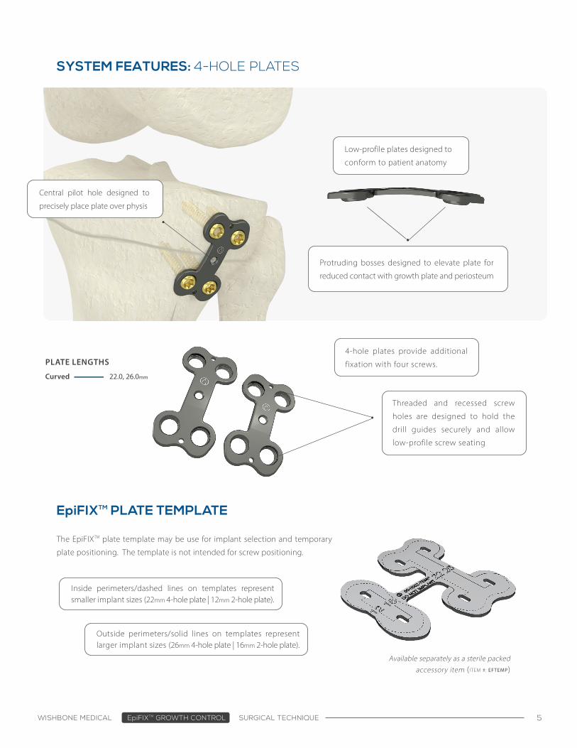
SYSTEM FEATURES: 4-HOLE PLATES
Protruding bosses designed to elevate plate for
reduced contact with growth plate and periosteum
Central pilot hole designed to
precisely place plate over physis
Threaded and recessed screw
holes are designed to hold the
drill guides securely and allow
low-profile screw seating
Low-profile plates designed to
conform to patient anatomy
PLATE LENGTHS
Curved 22.0, 26.0mm
EpiFIXTM PLATE TEMPLATE
4-hole plates provide additional
fixation with four screws.
The EpiFIXTM plate template may be use for implant selection and temporary
plate positioning. The template is not intended for screw positioning.
Available separately as a sterile packed accessory item (ITEM #: EFTEMP)
Inside perimeters/dashed lines on templates represent smaller implant sizes (22mm 4-hole plate | 12mm 2-hole plate).
Outside perimeters/solid lines on templates represent larger implant sizes (26mm 4-hole plate | 16mm 2-hole plate).
WISHBONE MEDICAL EpiFIXTM GROWTH CONTROL SURGICAL TECHNIQUE 6
4.5mm CANNULATED SCREWS
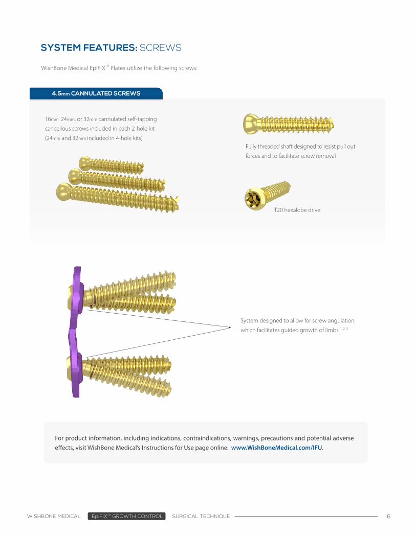
SYSTEM FEATURES: SCREWS
WishBone Medical EpiFIXTM Plates utilize the following screws:
16mm, 24mm, or 32mm cannulated self-tapping
cancellous screws included in each 2-hole kit
(24mm and 32mm included in 4-hole kits)
System designed to allow for screw angulation,
which facilitates guided growth of limbs 1, 2, 3
Fully threaded shaft designed to resist pull out
forces and to facilitate screw removal
T20 hexalobe drive
For product information, including indications, contraindications, warnings, precautions and potential adverse effects, visit WishBone Medical’s Instructions for Use page online: www.WishBoneMedical.com/IFU.
WISHBONE MEDICAL EpiFIXTM GROWTH CONTROL SURGICAL TECHNIQUE 7
Patient PositioningPlace the patient in a supine position with the leg abducted for fluoroscopy access and sterile prep in a customary fashion.
Before the Surgery
SURGICAL TECHNIQUE
Before the incision, select the appropriate size and type of growth control plate that best fits the patient’s anatomy. The EpiFIXTM plate template is available as a separate sterile packed accessory item.
Once the location is determined a 3cm longitudinal incision is made. The skin and the fascia is divided, avoiding damage to the periosteum.
Plate Sizing and Fixation
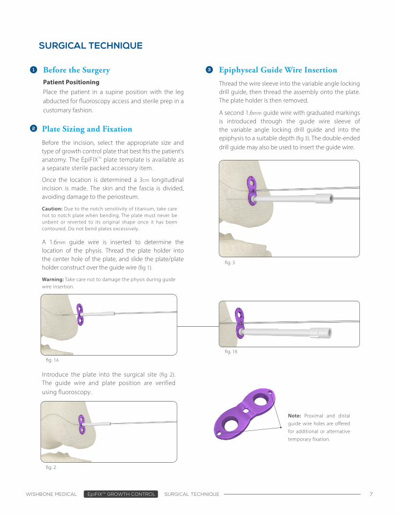
Thread the wire sleeve into the variable angle locking drill guide, then thread the assembly onto the plate. The plate holder is then removed.
A second 1.6mm guide wire with graduated markings is introduced through the guide wire sleeve of the variable angle locking drill guide and into the epiphysis to a suitable depth (fig 3). The double-ended drill guide may also be used to insert the guide wire.
Epiphyseal Guide Wire Insertion
fig. 1A
fig. 2
Note: Proximal and distal
guide wire holes are offered
for additional or alternative
temporary fixation.
Warning: Take care not to damage the physis during guide wire insertion.
fig. 3
fig. 1B
Caution: Due to the notch sensitivity of titanium, take care not to notch plate when bending. The plate must never be unbent or reverted to its original shape once it has been contoured. Do not bend plates excessively.
A 1.6mm guide wire is inserted to determine the location of the physis. Thread the plate holder into the center hole of the plate, and slide the plate/plate holder construct over the guide wire (fig 1).
Introduce the plate into the surgical site (fig 2). The guide wire and plate position are verified using fluoroscopy.
WISHBONE MEDICAL EpiFIXTM GROWTH CONTROL SURGICAL TECHNIQUE 8
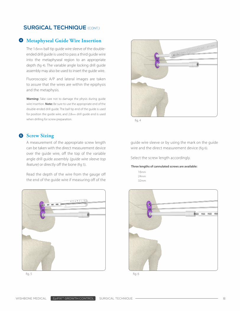
Metaphyseal Guide Wire Insertion
The 1.6mm ball tip guide wire sleeve of the double-ended drill guide is used to pass a third guide wire into the metaphyseal region to an appropriate depth (fig 4). The variable angle locking drill guide assembly may also be used to insert the guide wire.
Screw Sizing
SURGICAL TECHNIQUE (CONT.)
Three lengths of cannulated screws are available:
16mm
24mm
32mm
A measurement of the appropriate screw length can be taken with the direct measurement device over the guide wire, off the top of the variable angle drill guide assembly (guide wire sleeve top feature) or directly off the bone (fig 5).
Read the depth of the wire from the gauge off the end of the guide wire if measuring off of the
Fluoroscopic A/P and lateral images are taken to assure that the wires are within the epiphysis and the metaphysis.
guide wire sleeve or by using the mark on the guide wire and the direct measurement device (fig 6).
Select the screw length accordingly.
fig. 4
fig. 5 fig. 6
Warning: Take care not to damage the physis during guide
wire insertion. Note: Be sure to use the appropriate end of the
double-ended drill guide. The ball tip end of the guide is used
for position the guide wire, and 2.8mm drill guide end is used
when drilling for screw preparation.
WISHBONE MEDICAL EpiFIXTM GROWTH CONTROL SURGICAL TECHNIQUE 9
SURGICAL TECHNIQUE (CONT.)
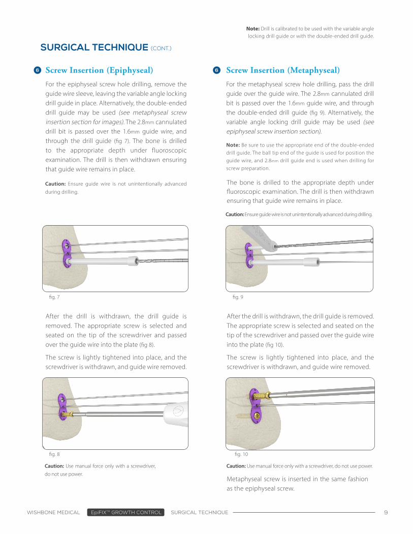
For the epiphyseal screw hole drilling, remove the guide wire sleeve, leaving the variable angle locking drill guide in place. Alternatively, the double-ended drill guide may be used (see metaphyseal screw insertion section for images). The 2.8mm cannulated drill bit is passed over the 1.6mm guide wire, and through the drill guide (fig 7). The bone is drilled to the appropriate depth under fluoroscopic examination. The drill is then withdrawn ensuring that guide wire remains in place.
Screw Insertion (Epiphyseal)
For the metaphyseal screw hole drilling, pass the drill guide over the guide wire. The 2.8mm cannulated drill bit is passed over the 1.6mm guide wire, and through the double-ended drill guide (fig 9). Alternatively, the variable angle locking drill guide may be used (see epiphyseal screw insertion section).
Note: Drill is calibrated to be used with the variable angle locking drill guide or with the double-ended drill guide.
Metaphyseal screw is inserted in the same fashion as the epiphyseal screw.
After the drill is withdrawn, the drill guide is removed. The appropriate screw is selected and seated on the tip of the screwdriver and passed over the guide wire into the plate (fig 10).
The screw is lightly tightened into place, and the screwdriver is withdrawn, and guide wire removed.
After the drill is withdrawn, the drill guide is removed. The appropriate screw is selected and seated on the tip of the screwdriver and passed over the guide wire into the plate (fig 8).
The screw is lightly tightened into place, and the screwdriver is withdrawn, and guide wire removed.
Screw Insertion (Metaphyseal)
fig. 7
fig. 8 fig. 10
fig. 9
Caution: Ensure guide wire is not unintentionally advanced
during drilling.
Caution: Ensure guide wire is not unintentionally advanced during drilling.
Note: Be sure to use the appropriate end of the double-ended drill guide. The ball tip end of the guide is used for position the guide wire, and 2.8mm drill guide end is used when drilling for screw preparation.
The bone is drilled to the appropriate depth under fluoroscopic examination. The drill is then withdrawn ensuring that guide wire remains in place.
Caution: Use manual force only with a screwdriver, do not use power.Caution: Use manual force only with a screwdriver,
do not use power.
WISHBONE MEDICAL EpiFIXTM GROWTH CONTROL SURGICAL TECHNIQUE 10
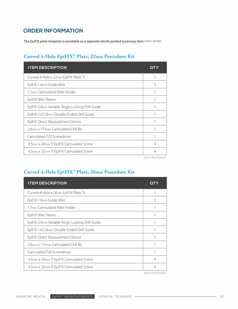
Removal
SURGICAL TECHNIQUE (CONT.)
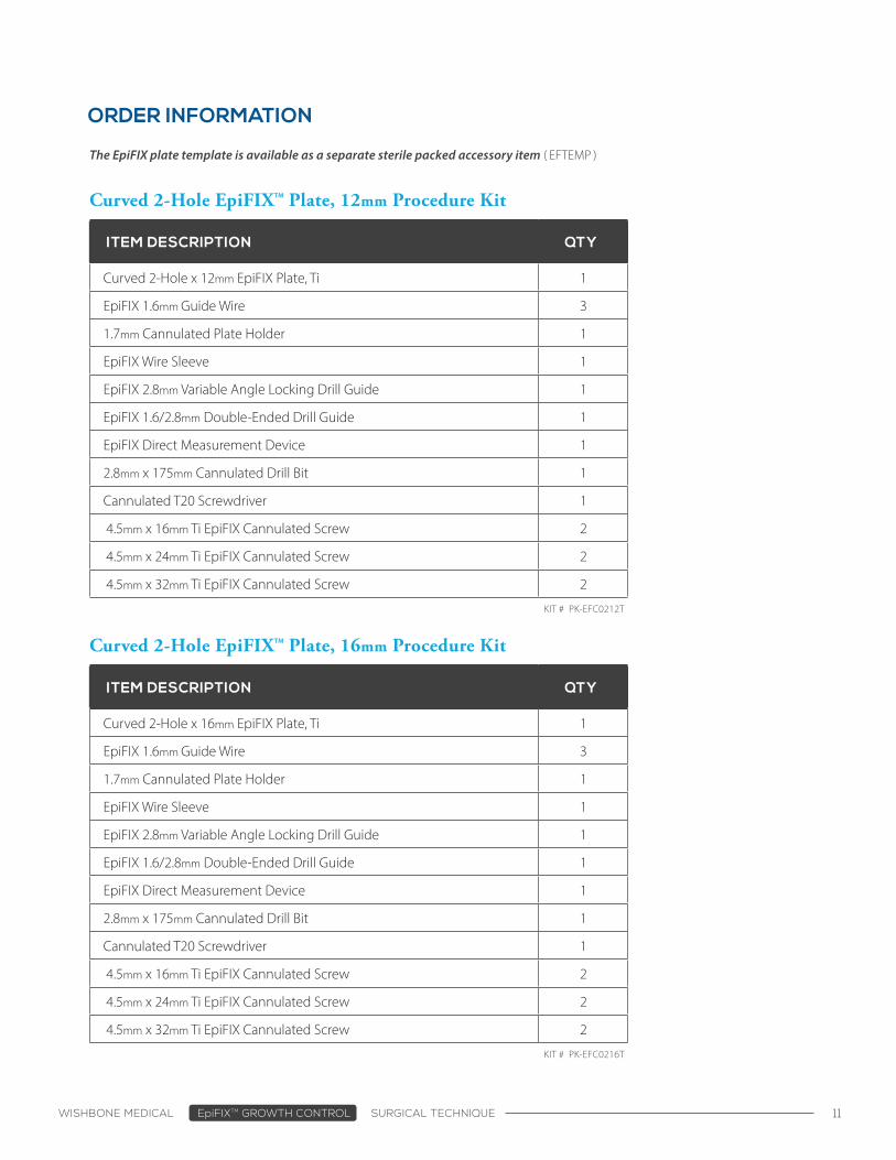
Screws and plate are imaged fluoroscopically in
order to ensure that screws are fully seated with
no gap between plate-bone interfaces.
Wound is closed in the customary fashion.
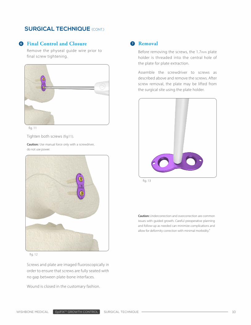
Tighten both screws (fig11).
Before removing the screws, the 1.7mm plate holder is threaded into the central hole of the plate for plate extraction.
Assemble the screwdriver to screws as described above and remove the screws. After screw removal, the plate may be lifted from the surgical site using the plate holder.
Remove the physeal guide wire prior to final screw tightening.
Final Control and Closure
fig. 11
fig. 12
fig. 13
Caution: Undercorrection and overcorrection are common
issues with guided growth. Careful preoperative planning
and follow-up as needed can minimize complications and
allow for deformity correction with minimal morbidity.4
Caution: Use manual force only with a screwdriver,
do not use power.
WISHBONE MEDICAL EpiFIXTM GROWTH CONTROL SURGICAL TECHNIQUE 11
ORDER INFORMATION
ITEM DESCRIPTION QTY
Curved 2-Hole x 12mm EpiFIX Plate, Ti 1
EpiFIX 1.6mm Guide Wire 3
1.7mm Cannulated Plate Holder 1
EpiFIX Wire Sleeve 1
EpiFIX 2.8mm Variable Angle Locking Drill Guide 1
EpiFIX 1.6/2.8mm Double-Ended Drill Guide 1
EpiFIX Direct Measurement Device 1
2.8mm x 175mm Cannulated Drill Bit 1
Cannulated T20 Screwdriver 1
4.5mm x 16mm Ti EpiFIX Cannulated Screw 2
4.5mm x 24mm Ti EpiFIX Cannulated Screw 2
4.5mm x 32mm Ti EpiFIX Cannulated Screw 2
Curved 2-Hole EpiFIXTM Plate, 12mm Procedure Kit
KIT # PK-EFC0212T
ITEM DESCRIPTION QTY
Curved 2-Hole x 16mm EpiFIX Plate, Ti 1
EpiFIX 1.6mm Guide Wire 3
1.7mm Cannulated Plate Holder 1
EpiFIX Wire Sleeve 1
EpiFIX 2.8mm Variable Angle Locking Drill Guide 1
EpiFIX 1.6/2.8mm Double-Ended Drill Guide 1
EpiFIX Direct Measurement Device 1
2.8mm x 175mm Cannulated Drill Bit 1
Cannulated T20 Screwdriver 1
4.5mm x 16mm Ti EpiFIX Cannulated Screw 2
4.5mm x 24mm Ti EpiFIX Cannulated Screw 2
4.5mm x 32mm Ti EpiFIX Cannulated Screw 2
Curved 2-Hole EpiFIXTM Plate, 16mm Procedure Kit
KIT # PK-EFC0216T
The EpiFIX plate template is available as a separate sterile packed accessory item ( EFTEMP )
WISHBONE MEDICAL EpiFIXTM GROWTH CONTROL SURGICAL TECHNIQUE 12
ORDER INFORMATION
ITEM DESCRIPTION QTY
Curved 4-Hole x 22mm EpiFIX Plate, Ti 1
EpiFIX 1.6mm Guide Wire 3
1.7mm Cannulated Plate Holder 1
EpiFIX Wire Sleeve 1
EpiFIX 2.8mm Variable Angle Locking Drill Guide 1
EpiFIX 1.6/2.8mm Double-Ended Drill Guide 1
EpiFIX Direct Measurement Device 1
2.8mm x 175mm Cannulated Drill Bit 1
Cannulated T20 Screwdriver 1
4.5mm x 24mm Ti EpiFIX Cannulated Screw 4
4.5mm x 32mm Ti EpiFIX Cannulated Screw 4
Curved 4-Hole EpiFIXTM Plate, 22mm Procedure Kit
KIT # PK-EFC0422T
ITEM DESCRIPTION QTY
Curved 4-Hole x 26mm EpiFIX Plate, Ti 1
EpiFIX 1.6mm Guide Wire 3
1.7mm Cannulated Plate Holder 1
EpiFIX Wire Sleeve 1
EpiFIX 2.8mm Variable Angle Locking Drill Guide 1
EpiFIX 1.6/2.8mm Double-Ended Drill Guide 1
EpiFIX Direct Measurement Device 1
2.8mm x 175mm Cannulated Drill Bit 1
Cannulated T20 Screwdriver 1
4.5mm x 24mm Ti EpiFIX Cannulated Screw 4
4.5mm x 32mm Ti EpiFIX Cannulated Screw 4
Curved 4-Hole EpiFIXTM Plate, 26mm Procedure Kit
KIT # PK-EFC0426T
The EpiFIX plate template is available as a separate sterile packed accessory item (ITEM #: EFTEMP)

WISHBONE MEDICAL EpiFIXTM GROWTH CONTROL SURGICAL TECHNIQUE 13
REFERENCES
1. Danino B, Rödl R, Herzenberg JE, Shabtai L, Grill F, Narayanan U, Segev E, Wientroub S. Guided growth: preliminary results of a multinational study of 967 physes in 537 patients. J Child Orthop 2018;12:91-96. DOI 10.1302/1863-2548.12.170050.
2. Stevens PM. Guided Growth for Angular Correction. J Pediatr Orthop. Volume 27, Number 3. April/May 2007.
3. Balla MS, Bruce CE, Nayagam S. Correcting genu varum and genu valgum in children by guided growth. J Bone Joint Surg. Vol. 92-B, No. 2, February 2010.
4. Saran N, Rathjen KE. Guided growth for the correction of pediatric lower limb angular deformity. J Am Acad Orthop Surg. 2010;18:528–36.

2150 North Pointe DrWarsaw, IN 46582
+1-574-306-4006
WishBoneMedical.com
© 2019 WishBone Medical, Inc. | LBL-ST-EF REV CTMTM
All trademarks herein are the property of WishBone Medical, Inc. or its subsidiaries unless otherwise indicated. This material is intended for the sole use and benefit of Health Care Professionals and the WishBone Medical Sales Force. It is not to be redistributed, duplicated or disclosed without the express written consent of WishBone Medical. All WishBone EpiFIXTM Growth Control Plating System kits are only available as single-use, sterile packed kits. Always confirm product expiration date prior to use.
For product information, including indications, contraindications, warnings, precautions and potential adverse effects, visit WishBone Medical’s Instructions for Use page online: www.WishBoneMedical.com/IFU.