Embed Size (px)
Citation preview
maxon motor ag Brünigstrasse 220 P.O.Box 263 CH-6072 Sachseln Phone +41 (41) 666 15 00 Fax +41 (41) 666 15 50 www.maxonmotor.com
Edition January 2010
EPOS2 Positioning Controller
Cable Starting Set
maxon motor control
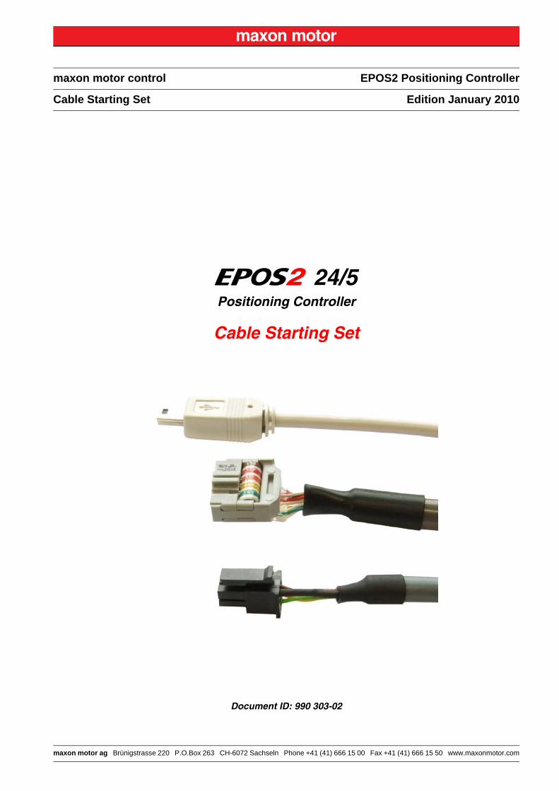
24/5Positioning Controller
Cable Starting Set
Document ID: 990 303-02
maxon motor controlA-2 Document ID: 990 303-02 V1 en EPOS2 Positioning Controller
Edition: January 2010 EPOS2 24/5 Cable Starting Set© 2010 maxon motor. Subject to change without prior notice.
PLEASE READ THIS FIRST
These instructions are intended for qualified technical personnel. Prior commencing with anyactivities …• you must carefully read and understand this manual and• you must follow the instructions given therein.
We have tried to provide you with all information necessary to install and commission the equipment in a secure, safe and time-saving manner. Our main focus is …
• to familiarize you with all relevant technical aspects,
• to let you know the easiest way of doing,
• to alert you of any possibly dangerous situation you might encounter or that you might cause if you do not follow the description,
• to write as little and to say as much as possible and
• not to bore you with things you already know.
Likewise, we tried to skip repetitive information! Thus, you will find things mentioned just once. If, for example, an earlier mentioned action fits other occasions you then will be directed to that text passage with a respective reference.
Follow any stated reference – observe respective information – then go back and continue withthe task!
PREREQUISITES FOR PERMISSION TO COMMENCE INSTALLATION
The EPOS2 24/5 is considered as partly completed machinery according to EU’s directive 2006/42/EC, Article 2, Clause (g) and therefore is intended to be incorporated into or assembled with other machinery or other partly completed machinery or equipment.
You must not put the device into service, …• unless you have made completely sure that the other machinery – the surrounding system the device
is intended to be incorporated to – fully complies with the requirements stated in the EU directive 2006/42/EC!
• unless the surrounding system fulfills all relevant health and safety aspects!• unless all respective interfaces have been established and fulfill the stated requirements!
maxon motor controlEPOS2 Positioning Controller Document ID: 990 303-02 V1 en A-3EPOS2 24/5 Cable Starting Set Edition: January 2010
© 2010 maxon motor. Subject to change without prior notice.
1 About this Document 5
2 Introduction 8
2.1 Documentation Structure - - - - - - - - - - - - - - - - - - - - - - - - - - - - - - - - - - - - - 8
2.2 Safety Precautions - - - - - - - - - - - - - - - - - - - - - - - - - - - - - - - - - - - - - - - - - 9
3 Cables 10
3.1 Important Notice: Prerequisites for Permission to commence Installation - - 10
3.2 Tools - - - - - - - - - - - - - - - - - - - - - - - - - - - - - - - - - - - - - - - - - - - - - - - - - - 10
3.3 Cable Selector - - - - - - - - - - - - - - - - - - - - - - - - - - - - - - - - - - - - - - - - - - - 11
3.4 Cable Assemblies - - - - - - - - - - - - - - - - - - - - - - - - - - - - - - - - - - - - - - - - - 123.4.1 EPOS Power Cable (275829) – Connector J1 - - - - - - - - - - - - - - - - - - - - - - - - - - - - 12
3.4.2 EPOS Motor Cable (275851) – Connector J2 - - - - - - - - - - - - - - - - - - - - - - - - - - - - - 13
3.4.3 EPOS Hall Sensor Cable (275878) – Connector J3- - - - - - - - - - - - - - - - - - - - - - - - - 14
3.4.4 EPOS Encoder Cable (275934) – Connector J4 - - - - - - - - - - - - - - - - - - - - - - - - - - - 15
3.4.5 EPOS Signal Cable 1 (275932) – Connector J5 - - - - - - - - - - - - - - - - - - - - - - - - - - - 17
3.4.6 EPOS RS232-COM Cable (275900) – Connector J6 - - - - - - - - - - - - - - - - - - - - - - - - 19
3.4.7 EPOS2 USB Type A-mini B Cable (370513) – Connector J9 - - - - - - - - - - - - - - - - - - 20
3.4.8 EPOS CAN-COM Cable (275908) – Connector J7 or J8 - - - - - - - - - - - - - - - - - - - - - 21
3.4.9 EPOS CAN-CAN Cable (275926) – Connector J7 or J8- - - - - - - - - - - - - - - - - - - - - - 22
3.5 EPOS2 24/5 Connector Set (384915) - - - - - - - - - - - - - - - - - - - - - - - - - - - 23
TABLE OF CONTENTS
maxon motor controlA-4 Document ID: 990 303-02 V1 en EPOS2 Positioning Controller
Edition: January 2010 EPOS2 24/5 Cable Starting Set© 2010 maxon motor. Subject to change without prior notice.
• • p a g e i n t e n t i o n a l l y l e f t b l a n k • •
maxon motor controlEPOS2 Positioning Controller Document ID: 990 303-02 V1 en 1-5EPOS2 24/5 Cable Starting Set Edition: January 2010
© 2010 maxon motor. Subject to change without prior notice.
1 About this Document
1.1 Intended PurposeThe purpose of the present document is to familiarize you with the described equipment and the tasks on safe and adequate installation and/or commissioning.
Observing the described instructions in this document will help you …
• to avoid dangerous situations,
• to keep installation and/or commissioning time at a minimum and
• to increase reliability and service life of the described equipment.
Use for other and/or additional purposes is not permitted. maxon motor, the manufacturer of the equip-ment described, does not assume any liability for loss or damage that may arise from any other and/or additional use than the intended purpose.
1.2 Target AudienceThis document is meant for trained and skilled personnel working with the equipment described. It con-veys information on how to understand and fulfill the respective work and duties.
This document is a reference book. It does require particular knowledge and expertise specific to the equipment described.
1.3 How to useTake note of the following notations and codes which will be used throughout the document.
Table 1-1 Notations used in this Document
1.4 Symbols and Signs
1.4.1 Safety Alerts
Take note of when and why the alerts will be used and what the consequences are if you shouldfail to observe them!
Safety alerts are composed of…
• a signal word,
• a description of type and/or source of the danger,
• the consequence if the alert is being ignored, and
• explanations on how to avoid the hazard.
Following types will be used:
1) DANGERIndicates an imminently hazardous situation. If not avoided, the situation will result in death or serious injury.
Notation Explanation
(n) referring to an item (such as order number, list item, etc.)
denotes “see”, “see also”, “take note of” or “go to”
maxon motor control1-6 Document ID: 990 303-02 V1 en EPOS2 Positioning Controller
Edition: January 2010 EPOS2 24/5 Cable Starting Set© 2010 maxon motor. Subject to change without prior notice.
2) WARNINGIndicates a potentially hazardous situation. If not avoided, the situation can result in death or serious injury.
3) CAUTIONIndicates a probable hazardous situation and is also used to alert against unsafe practices. If not avoided, the situation may result in minor or moderate injury.
Example:
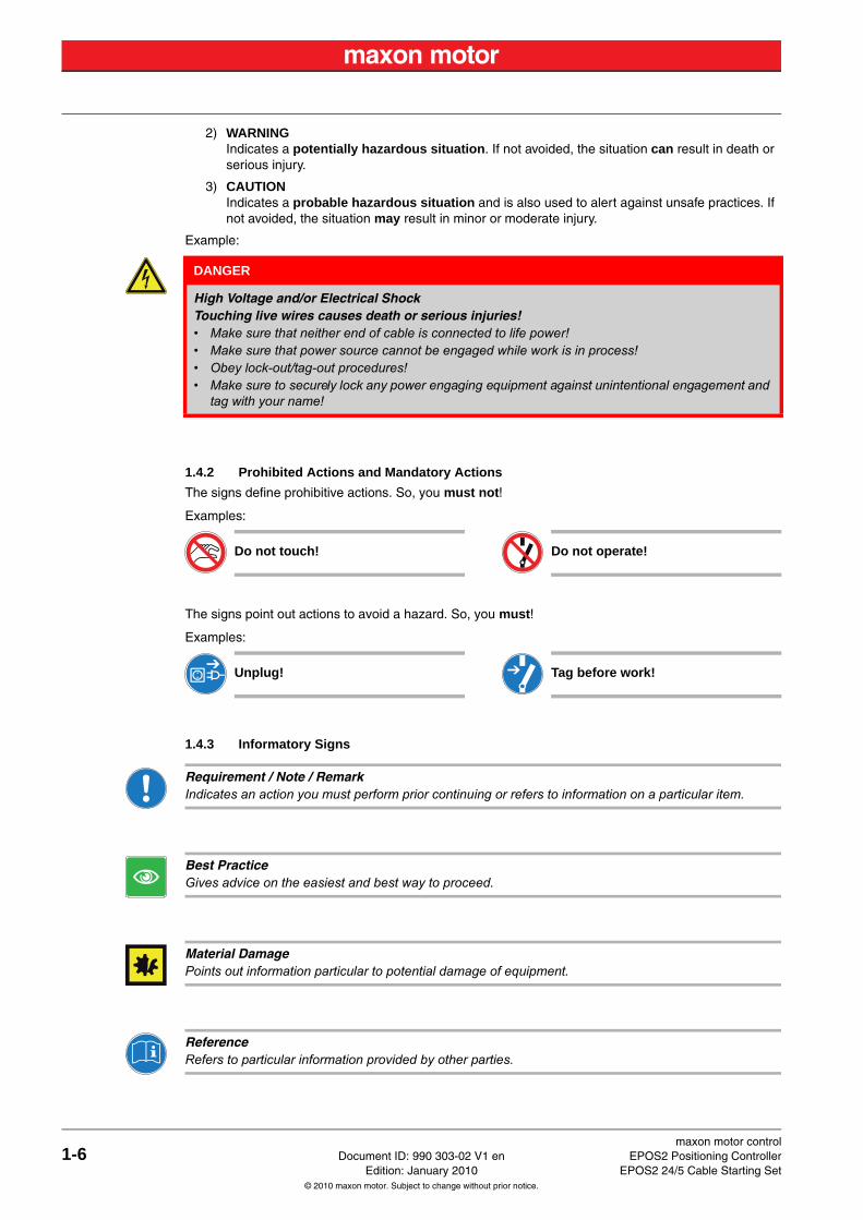
1.4.2 Prohibited Actions and Mandatory Actions
The signs define prohibitive actions. So, you must not!
Examples:
The signs point out actions to avoid a hazard. So, you must!
Examples:
1.4.3 Informatory Signs
Requirement / Note / RemarkIndicates an action you must perform prior continuing or refers to information on a particular item.
Best PracticeGives advice on the easiest and best way to proceed.
Material DamagePoints out information particular to potential damage of equipment.
ReferenceRefers to particular information provided by other parties.
DANGER
High Voltage and/or Electrical ShockTouching live wires causes death or serious injuries!• Make sure that neither end of cable is connected to life power!• Make sure that power source cannot be engaged while work is in process!• Obey lock-out/tag-out procedures!• Make sure to securely lock any power engaging equipment against unintentional engagement and
tag with your name!
Do not touch! Do not operate!
Unplug! Tag before work!
maxon motor controlEPOS2 Positioning Controller Document ID: 990 303-02 V1 en 1-7EPOS2 24/5 Cable Starting Set Edition: January 2010
© 2010 maxon motor. Subject to change without prior notice.
1.5 Trademarks and Brand NamesFor easier legibility, registered brand names are listed below and will not be further tagged with their respective trademark. It must be understood that the brands (the below list is not necessarily conclud-ing) are protected by copyright and/or other intellectual property rights even if their legal trademarks are omitted in the later course of this document.
Table 1-2 Brand Names and Trademark Owners
1.6 Copyright© 2010 maxon motor. All rights reserved.
The present document – including all parts thereof – is protected by copyright. Any use (including repro-duction, translation, microfilming and other means of electronic data processing) beyond the narrow restrictions of the copyright law without the prior approval of maxon motor ag, is not permitted and sub-ject to persecution under the applicable law.
maxon motor agBrünigstrasse 220P.O.Box 263CH-6072 SachselnSwitzerland
Phone +41 (41) 666 15 00Fax +41 (41) 666 15 50
www.maxonmotor.com
The brand name(s) … … is/are a registered trademark(s) of …
Micro-Fit™Mini-Fit Jr.™
© Molex, USA-Lisle, IL
maxon motor control2-8 Document ID: 990 303-02 V1 en EPOS2 Positioning Controller
Edition: January 2010 EPOS2 24/5 Cable Starting Set© 2010 maxon motor. Subject to change without prior notice.
2 Introduction
The present document provides you with information on the wiring details for each cable which will be used with the EPOS2 24/5 hardware. It contains pictures, drawings, cable specification, pin assignment and detailed connector information. The included «Cable Selector» will help you to choose the correct cable for the setup you are using.
Find the latest edition of the present document, as well as additional documentation and software to the EPOS2 24/5 Positioning Controller also on the internet:
www.maxonmotor.com – category «Service & Downloads»
shop.maxonmotor.com
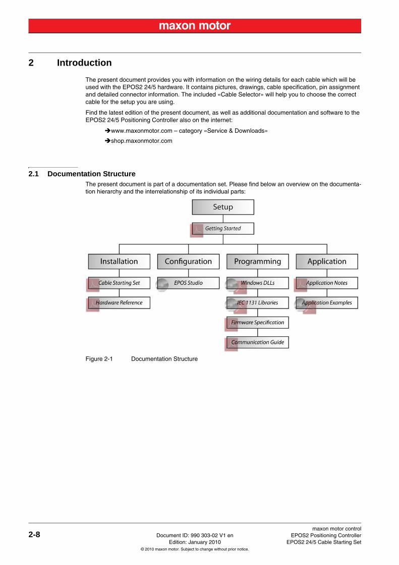
2.1 Documentation StructureThe present document is part of a documentation set. Please find below an overview on the documenta-tion hierarchy and the interrelationship of its individual parts:
Figure 2-1 Documentation Structure
maxon motor controlEPOS2 Positioning Controller Document ID: 990 303-02 V1 en 2-9EPOS2 24/5 Cable Starting Set Edition: January 2010
© 2010 maxon motor. Subject to change without prior notice.
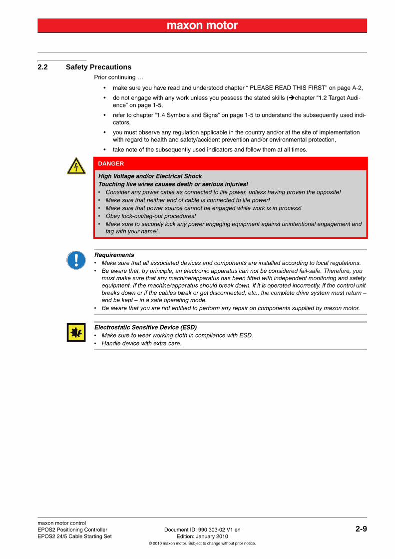
2.2 Safety PrecautionsPrior continuing …
• make sure you have read and understood chapter “ PLEASE READ THIS FIRST” on page A-2,
• do not engage with any work unless you possess the stated skills (chapter “1.2 Target Audi-ence” on page 1-5,
• refer to chapter “1.4 Symbols and Signs” on page 1-5 to understand the subsequently used indi-cators,
• you must observe any regulation applicable in the country and/or at the site of implementation with regard to health and safety/accident prevention and/or environmental protection,
• take note of the subsequently used indicators and follow them at all times.
Requirements• Make sure that all associated devices and components are installed according to local regulations.• Be aware that, by principle, an electronic apparatus can not be considered fail-safe. Therefore, you
must make sure that any machine/apparatus has been fitted with independent monitoring and safety equipment. If the machine/apparatus should break down, if it is operated incorrectly, if the control unit breaks down or if the cables break or get disconnected, etc., the complete drive system must return – and be kept – in a safe operating mode.
• Be aware that you are not entitled to perform any repair on components supplied by maxon motor.
Electrostatic Sensitive Device (ESD)• Make sure to wear working cloth in compliance with ESD.• Handle device with extra care.
DANGER
High Voltage and/or Electrical ShockTouching live wires causes death or serious injuries!• Consider any power cable as connected to life power, unless having proven the opposite!• Make sure that neither end of cable is connected to life power!• Make sure that power source cannot be engaged while work is in process!• Obey lock-out/tag-out procedures!• Make sure to securely lock any power engaging equipment against unintentional engagement and
tag with your name!
maxon motor control3-10 Document ID: 990 303-02 V1 en EPOS2 Positioning Controller
Edition: January 2010 EPOS2 24/5 Cable Starting Set© 2010 maxon motor. Subject to change without prior notice.
3 Cables
3.1 Important Notice: Prerequisites for Permission to commence InstallationThe EPOS2 24/5 is considered as partly completed machinery according to EU’s directive 2006/42/EC, Article 2, Clause (g) and therefore is only intended to be incorporated into or assembled with other machinery or other partly completed machinery or equipment.
3.2 ToolsIf you should decide not to use the ready-made cable assemblies, we strongly recommenced to employ the following hand tools.
Table 3-3 Recommended Tools
WARNING
Risk of InjuryOperating the device without the full compliance of the surrounding system with the EU direc-tive 2006/42/EC may cause serious injuries!• Do not operate the device, unless you have made sure that the other machinery fulfills the require-
ments stated in EU’s directive!• Do not operate the device, unless the surrounding system fulfills all relevant health and safety
aspects!• Do not operate the device, unless all respective interfaces have been established and fulfill the
stated requirements!
Tools
CrimperMolex hand crimper (63819-0000)
Molex hand crimper (63819-0900)
maxon motor controlEPOS2 Positioning Controller Document ID: 990 303-02 V1 en 3-11EPOS2 24/5 Cable Starting Set Edition: January 2010
© 2010 maxon motor. Subject to change without prior notice.
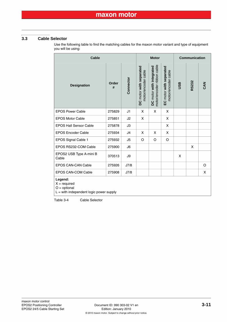
3.3 Cable SelectorUse the following table to find the matching cables for the maxon motor variant and type of equipment you will be using:
Table 3-4 Cable Selector
Cable Motor Communication
DesignationOrder
#
Co
nn
ecto
r
DC
mot
or w
ith
sep
arat
edm
otor
/enc
oder
cab
le
DC
mot
or w
ith
inte
gra
ted
mot
or/e
ncod
er r
ibbo
n ca
ble
EC
mot
or w
ith
sep
arat
edm
otor
/enc
oder
cab
le
US
B
RS
232
CA
N
EPOS Power Cable 275829 J1 X X X
EPOS Motor Cable 275851 J2 X X
EPOS Hall Sensor Cable 275878 J3 X
EPOS Encoder Cable 275934 J4 X X X
EPOS Signal Cable 1 275932 J5 O O O
EPOS RS232-COM Cable 275900 J6 X
EPOS2 USB Type A-mini B Cable
370513 J9 X
EPOS CAN-CAN Cable 275926 J7/8 O
EPOS CAN-COM Cable 275908 J7/8 X
Legend:X = requiredO = optionalL = with independent logic power supply
maxon motor control3-12 Document ID: 990 303-02 V1 en EPOS2 Positioning Controller
Edition: January 2010 EPOS2 24/5 Cable Starting Set© 2010 maxon motor. Subject to change without prior notice.
3.4 Cable Assemblies
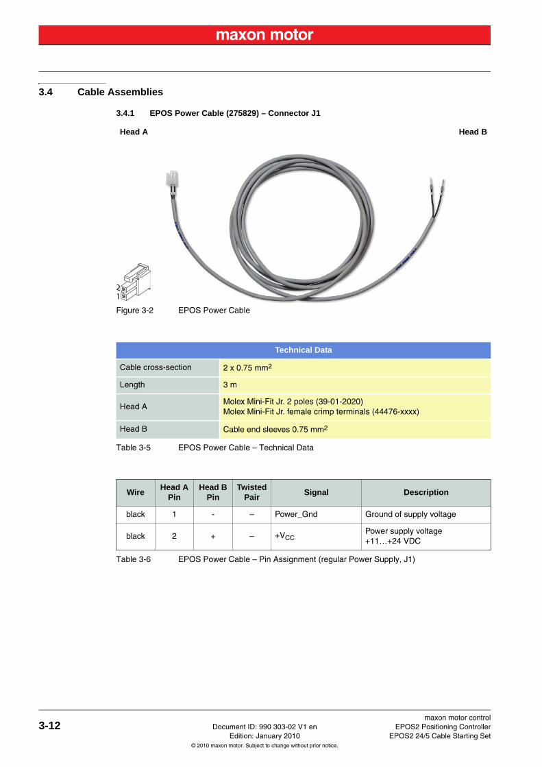
3.4.1 EPOS Power Cable (275829) – Connector J1
Figure 3-2 EPOS Power Cable
Table 3-5 EPOS Power Cable – Technical Data
Table 3-6 EPOS Power Cable – Pin Assignment (regular Power Supply, J1)
Head A Head B
Technical Data
Cable cross-section 2 x 0.75 mm2
Length 3 m
Head AMolex Mini-Fit Jr. 2 poles (39-01-2020)Molex Mini-Fit Jr. female crimp terminals (44476-xxxx)
Head B Cable end sleeves 0.75 mm2
WireHead A
PinHead B
PinTwisted
PairSignal Description
black 1 - – Power_Gnd Ground of supply voltage
black 2 + – +VCCPower supply voltage+11…+24 VDC
maxon motor controlEPOS2 Positioning Controller Document ID: 990 303-02 V1 en 3-13EPOS2 24/5 Cable Starting Set Edition: January 2010
© 2010 maxon motor. Subject to change without prior notice.
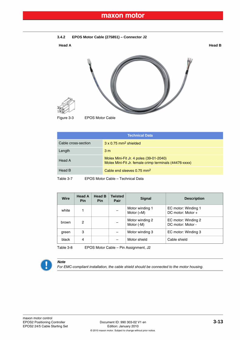
3.4.2 EPOS Motor Cable (275851) – Connector J2
Figure 3-3 EPOS Motor Cable
Table 3-7 EPOS Motor Cable – Technical Data
Table 3-8 EPOS Motor Cable – Pin Assignment, J2
NoteFor EMC-compliant installation, the cable shield should be connected to the motor housing.
Head A Head B
Technical Data
Cable cross-section 3 x 0.75 mm2 shielded
Length 3 m
Head AMolex Mini-Fit Jr. 4 poles (39-01-2040)Molex Mini-Fit Jr. female crimp terminals (44476-xxxx)
Head B Cable end sleeves 0.75 mm2
WireHead A
PinHead B
PinTwisted
PairSignal Description
white 1 1 –Motor winding 1Motor (+M)
EC motor: Winding 1DC motor: Motor +
brown 2 2 –Motor winding 2Motor (-M)
EC motor: Winding 2DC motor: Motor -
green 3 3 – Motor winding 3 EC motor: Winding 3
black 4 4 – Motor shield Cable shield
maxon motor control3-14 Document ID: 990 303-02 V1 en EPOS2 Positioning Controller
Edition: January 2010 EPOS2 24/5 Cable Starting Set© 2010 maxon motor. Subject to change without prior notice.
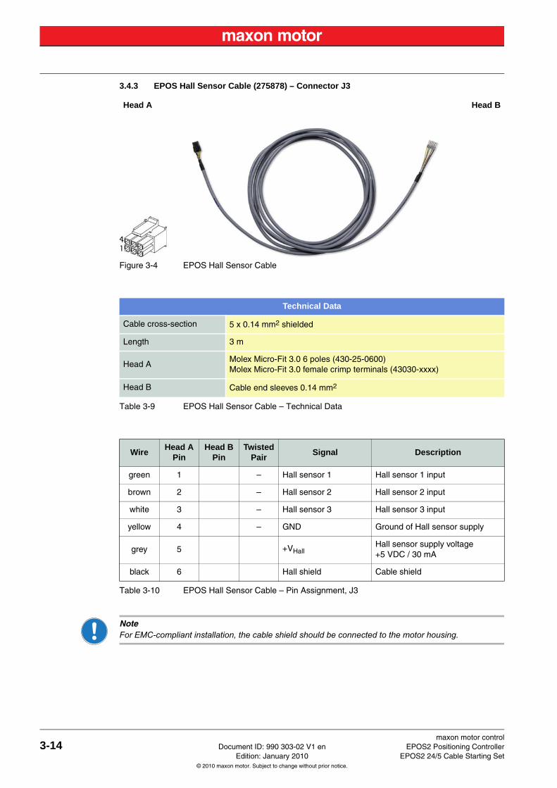
3.4.3 EPOS Hall Sensor Cable (275878) – Connector J3
Figure 3-4 EPOS Hall Sensor Cable
Table 3-9 EPOS Hall Sensor Cable – Technical Data
Table 3-10 EPOS Hall Sensor Cable – Pin Assignment, J3
NoteFor EMC-compliant installation, the cable shield should be connected to the motor housing.
Head A Head B
Technical Data
Cable cross-section 5 x 0.14 mm2 shielded
Length 3 m
Head AMolex Micro-Fit 3.0 6 poles (430-25-0600)Molex Micro-Fit 3.0 female crimp terminals (43030-xxxx)
Head B Cable end sleeves 0.14 mm2
WireHead A
PinHead B
PinTwisted
PairSignal Description
green 1 1 – Hall sensor 1 Hall sensor 1 input
brown 2 2 – Hall sensor 2 Hall sensor 2 input
white 3 3 – Hall sensor 3 Hall sensor 3 input
yellow 4 4 – GND Ground of Hall sensor supply
grey 5 5 +VHallHall sensor supply voltage+5 VDC / 30 mA
black 6 6 Hall shield Cable shield
maxon motor controlEPOS2 Positioning Controller Document ID: 990 303-02 V1 en 3-15EPOS2 24/5 Cable Starting Set Edition: January 2010
© 2010 maxon motor. Subject to change without prior notice.
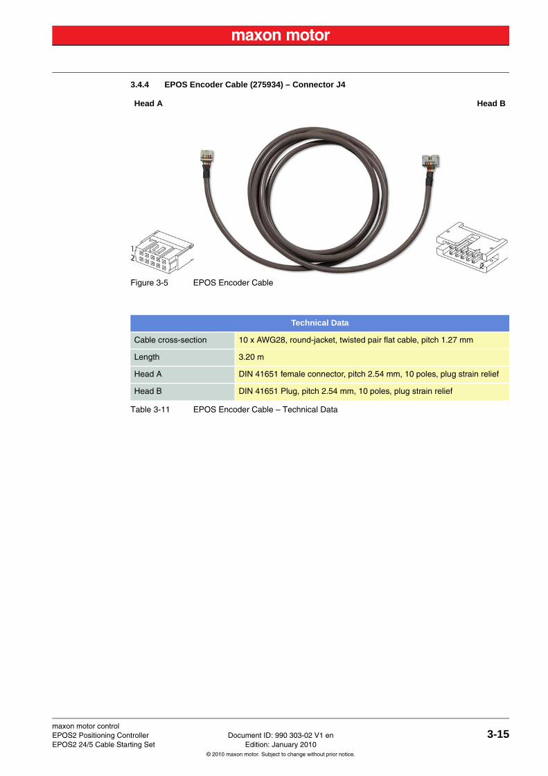
3.4.4 EPOS Encoder Cable (275934) – Connector J4
Figure 3-5 EPOS Encoder Cable
Table 3-11 EPOS Encoder Cable – Technical Data
Head A Head B
Technical Data
Cable cross-section 10 x AWG28, round-jacket, twisted pair flat cable, pitch 1.27 mm
Length 3.20 m
Head A DIN 41651 female connector, pitch 2.54 mm, 10 poles, plug strain relief
Head B DIN 41651 Plug, pitch 2.54 mm, 10 poles, plug strain relief
maxon motor control3-16 Document ID: 990 303-02 V1 en EPOS2 Positioning Controller
Edition: January 2010 EPOS2 24/5 Cable Starting Set© 2010 maxon motor. Subject to change without prior notice.
Table 3-12 EPOS Encoder Cable – Pin Assignment, J4
NoteEPOS encoder cable head B. The pin out suits, for example:
• maxon digital MR Encoder type S, M, ML, L all with Line Driver• maxon digital encoder HEDL 55_ with Line Driver RS 422
WireHead A
PinHead B
PinTwisted
PairSignal Description
brown 1 11
Motor + DC motor: Motor + *1)
white 2 2 +5 VDC / 100 mA Encoder supply voltage
red 3 32
GND Ground
white 4 4 Motor - DC motor: Motor - *1)
orange 5 53
Channel A\ Channel A complement
white 6 6 Channel A Channel A
yellow 7 74
Channel B\ Channel B complement
white 8 8 Channel B Channel B
green 9 95
Channel I\ Index complement
white 10 10 Channel I Index
Remark*1) only with maxon DC motors with digital MR encoder with Line Driver type S and M
maxon motor controlEPOS2 Positioning Controller Document ID: 990 303-02 V1 en 3-17EPOS2 24/5 Cable Starting Set Edition: January 2010
© 2010 maxon motor. Subject to change without prior notice.
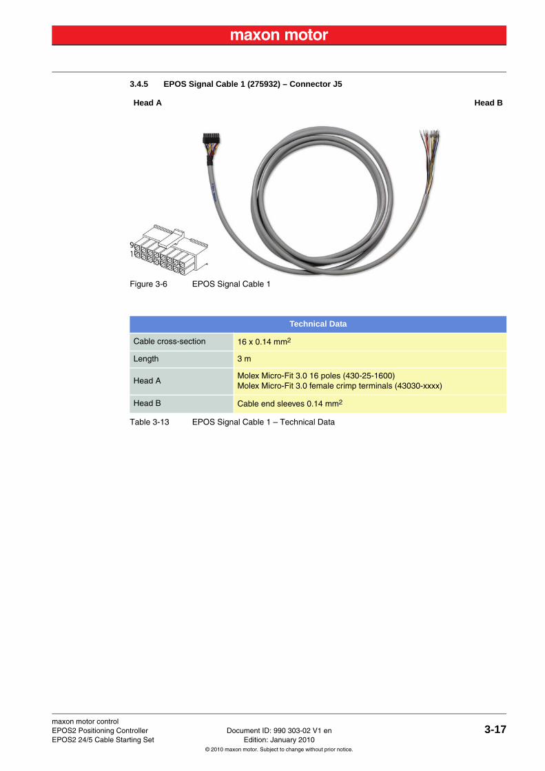
3.4.5 EPOS Signal Cable 1 (275932) – Connector J5
Figure 3-6 EPOS Signal Cable 1
Table 3-13 EPOS Signal Cable 1 – Technical Data
Head A Head B
Technical Data
Cable cross-section 16 x 0.14 mm2
Length 3 m
Head AMolex Micro-Fit 3.0 16 poles (430-25-1600)Molex Micro-Fit 3.0 female crimp terminals (43030-xxxx)
Head B Cable end sleeves 0.14 mm2
maxon motor control3-18 Document ID: 990 303-02 V1 en EPOS2 Positioning Controller
Edition: January 2010 EPOS2 24/5 Cable Starting Set© 2010 maxon motor. Subject to change without prior notice.
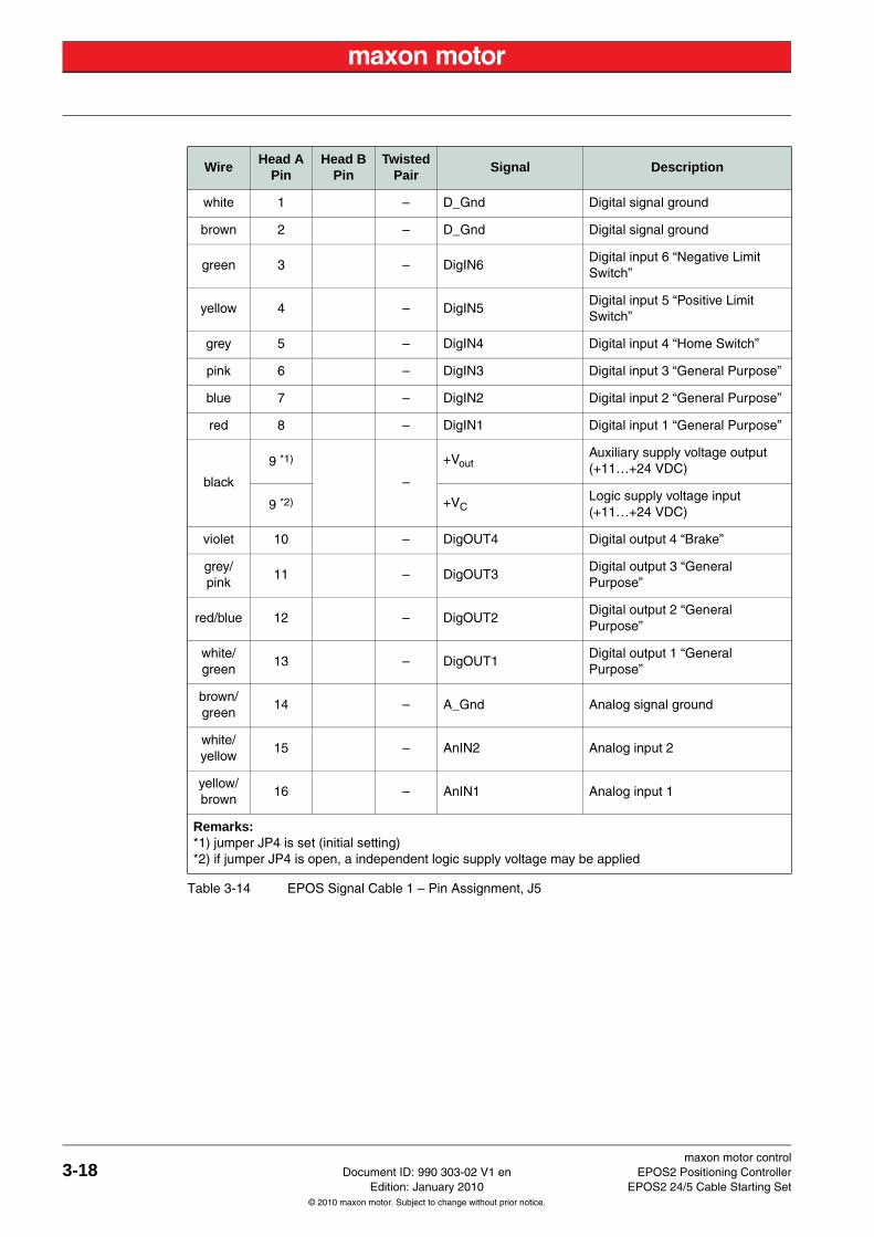
Table 3-14 EPOS Signal Cable 1 – Pin Assignment, J5
WireHead A
PinHead B
PinTwisted
PairSignal Description
white 1 1 – D_Gnd Digital signal ground
brown 2 2 – D_Gnd Digital signal ground
green 3 3 – DigIN6Digital input 6 “Negative Limit Switch”
yellow 4 4 – DigIN5Digital input 5 “Positive Limit Switch”
grey 5 5 – DigIN4 Digital input 4 “Home Switch”
pink 6 6 – DigIN3 Digital input 3 “General Purpose”
blue 7 7 – DigIN2 Digital input 2 “General Purpose”
red 8 8 – DigIN1 Digital input 1 “General Purpose”
black
9 *1)
9 –
+VoutAuxiliary supply voltage output (+11…+24 VDC)
9 *2) +VCLogic supply voltage input (+11…+24 VDC)
violet 10 10 – DigOUT4 Digital output 4 “Brake”
grey/pink
11 11 – DigOUT3Digital output 3 “General Purpose”
red/blue 12 12 – DigOUT2Digital output 2 “General Purpose”
white/green
13 13 – DigOUT1Digital output 1 “General Purpose”
brown/green
14 14 – A_Gnd Analog signal ground
white/yellow
15 15 – AnIN2 Analog input 2
yellow/brown
16 16 – AnIN1 Analog input 1
Remarks:*1) jumper JP4 is set (initial setting)*2) if jumper JP4 is open, a independent logic supply voltage may be applied
maxon motor controlEPOS2 Positioning Controller Document ID: 990 303-02 V1 en 3-19EPOS2 24/5 Cable Starting Set Edition: January 2010
© 2010 maxon motor. Subject to change without prior notice.
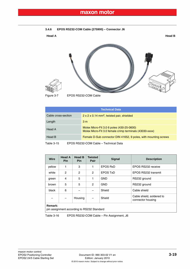
3.4.6 EPOS RS232-COM Cable (275900) – Connector J6
Figure 3-7 EPOS RS232-COM Cable
Table 3-15 EPOS RS232-COM Cable – Technical Data
Table 3-16 EPOS RS232-COM Cable – Pin Assignment, J6
Head A Head B
Technical Data
Cable cross-section 2 x 2 x 0.14 mm2, twisted pair, shielded
Length 3 m
Head AMolex Micro-Fit 3.0 6 poles (430-25-0600)Molex Micro-Fit 3.0 female crimp terminals (43030-xxxx)
Head B Female D-Sub connector DIN 41652, 9 poles, with mounting screws
WireHead A
PinHead B
PinTwisted
PairSignal Description
yellow 1 3 1 EPOS RxD EPOS RS232 receive
white 2 2 2 EPOS TxD EPOS RS232 transmit
green 4 5 1 GND RS232 ground
brown 5 5 2 GND RS232 ground
black 6 – – Shield Cable shield
– – Housing – ShieldCable shield, soldered to connector housing
Remark:pin assignment according to RS232 Standard
maxon motor control3-20 Document ID: 990 303-02 V1 en EPOS2 Positioning Controller
Edition: January 2010 EPOS2 24/5 Cable Starting Set© 2010 maxon motor. Subject to change without prior notice.
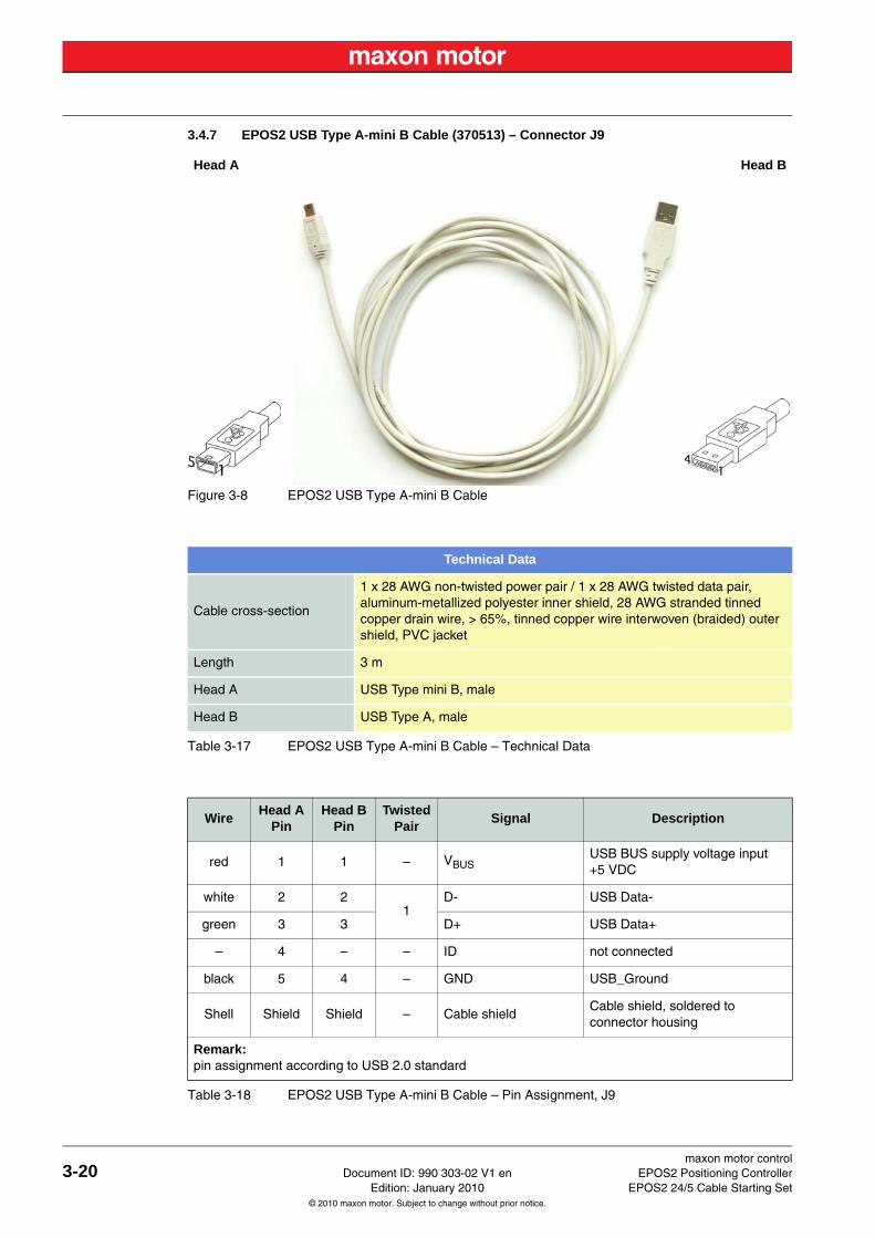
3.4.7 EPOS2 USB Type A-mini B Cable (370513) – Connector J9
Figure 3-8 EPOS2 USB Type A-mini B Cable
Table 3-17 EPOS2 USB Type A-mini B Cable – Technical Data
Table 3-18 EPOS2 USB Type A-mini B Cable – Pin Assignment, J9
Head A Head B
Technical Data
Cable cross-section
1 x 28 AWG non-twisted power pair / 1 x 28 AWG twisted data pair, aluminum-metallized polyester inner shield, 28 AWG stranded tinned copper drain wire, > 65%, tinned copper wire interwoven (braided) outer shield, PVC jacket
Length 3 m
Head A USB Type mini B, male
Head B USB Type A, male
WireHead A
PinHead B
PinTwisted
PairSignal Description
red 1 1 – VBUSUSB BUS supply voltage input+5 VDC
white 2 21
D- USB Data-
green 3 3 D+ USB Data+
– 4 – – ID not connected
black 5 4 – GND USB_Ground
Shell Shield Shield – Cable shieldCable shield, soldered to connector housing
Remark:pin assignment according to USB 2.0 standard
maxon motor controlEPOS2 Positioning Controller Document ID: 990 303-02 V1 en 3-21EPOS2 24/5 Cable Starting Set Edition: January 2010
© 2010 maxon motor. Subject to change without prior notice.
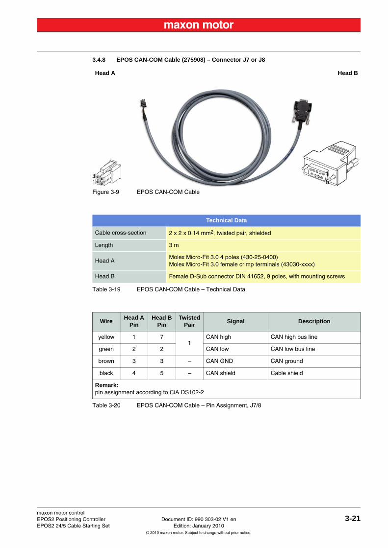
3.4.8 EPOS CAN-COM Cable (275908) – Connector J7 or J8
Figure 3-9 EPOS CAN-COM Cable
Table 3-19 EPOS CAN-COM Cable – Technical Data
Table 3-20 EPOS CAN-COM Cable – Pin Assignment, J7/8
Head A Head B
Technical Data
Cable cross-section 2 x 2 x 0.14 mm2, twisted pair, shielded
Length 3 m
Head AMolex Micro-Fit 3.0 4 poles (430-25-0400)Molex Micro-Fit 3.0 female crimp terminals (43030-xxxx)
Head B Female D-Sub connector DIN 41652, 9 poles, with mounting screws
WireHead A
PinHead B
PinTwisted
PairSignal Description
yellow 1 71
CAN high CAN high bus line
green 2 2 CAN low CAN low bus line
brown 3 3 – CAN GND CAN ground
black 4 5 – CAN shield Cable shield
Remark:pin assignment according to CiA DS102-2
maxon motor control3-22 Document ID: 990 303-02 V1 en EPOS2 Positioning Controller
Edition: January 2010 EPOS2 24/5 Cable Starting Set© 2010 maxon motor. Subject to change without prior notice.
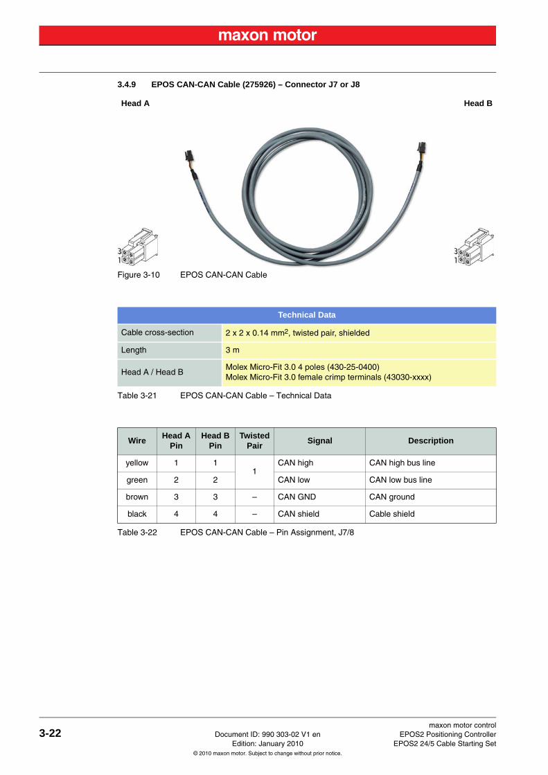
3.4.9 EPOS CAN-CAN Cable (275926) – Connector J7 or J8
Figure 3-10 EPOS CAN-CAN Cable
Table 3-21 EPOS CAN-CAN Cable – Technical Data
Table 3-22 EPOS CAN-CAN Cable – Pin Assignment, J7/8
Head A Head B
Technical Data
Cable cross-section 2 x 2 x 0.14 mm2, twisted pair, shielded
Length 3 m
Head A / Head BMolex Micro-Fit 3.0 4 poles (430-25-0400)Molex Micro-Fit 3.0 female crimp terminals (43030-xxxx)
WireHead A
PinHead B
PinTwisted
PairSignal Description
yellow 1 11
CAN high CAN high bus line
green 2 2 CAN low CAN low bus line
brown 3 3 – CAN GND CAN ground
black 4 4 – CAN shield Cable shield
maxon motor controlEPOS2 Positioning Controller Document ID: 990 303-02 V1 en 3-23EPOS2 24/5 Cable Starting Set Edition: January 2010
© 2010 maxon motor. Subject to change without prior notice.
3.5 EPOS2 24/5 Connector Set (384915)If you decide not to use the ready-made cable assemblies, you can take advantage of a prepackaged set containing all required connectors.The set contains following items:
Table 3-23 EPOS2 24/5 Connector Set – Content
Best PracticeFor best results use original manufacturer’s tools (chapter “3.2 Tools” on page 3-10).
Connector Specification Quantity
J1 Molex Mini-Fit Jr. 2 poles (39-01-2020) 1
J2 Molex Mini-Fit Jr. 4 poles (39-01-2040) 1
J3 / J6 Molex Micro-Fit 3.0 6 poles (430-25-0600) 2
J5 Molex Micro-Fit 3.0 16 poles (430-25-1600) 1
J7 / J8 Molex Micro-Fit 3.0 4 poles (430-25-0400) 2
Molex Mini-Fit Jr. female crimp terminal (44476-1111) 8
Molex Micro-Fit 3.0 female crimp terminal (43030-0010) 38
Tyco C42334-A421-C42 (right), encoder clip right 1
Tyco C42334-A421-C52 (left), encoder clip left 1
maxon motor controlZ-24 Document ID: 990 303-02 V1 en EPOS2 Positioning Controller
Edition: January 2010 EPOS2 24/5 Cable Starting Set© 2010 maxon motor. Subject to change without prior notice.
Figure 2-1 Documentation Structure - - - - - - - - - - - - - - - - - - - - - - - - - - - - - - - - - - - - - - - - - - - 8
Figure 3-2 EPOS Power Cable - - - - - - - - - - - - - - - - - - - - - - - - - - - - - - - - - - - - - - - - - - - - - - 12
Figure 3-3 EPOS Motor Cable - - - - - - - - - - - - - - - - - - - - - - - - - - - - - - - - - - - - - - - - - - - - - - 13
Figure 3-4 EPOS Hall Sensor Cable - - - - - - - - - - - - - - - - - - - - - - - - - - - - - - - - - - - - - - - - - - 14
Figure 3-5 EPOS Encoder Cable- - - - - - - - - - - - - - - - - - - - - - - - - - - - - - - - - - - - - - - - - - - - - 15
Figure 3-6 EPOS Signal Cable 1 - - - - - - - - - - - - - - - - - - - - - - - - - - - - - - - - - - - - - - - - - - - - - 17
Figure 3-7 EPOS RS232-COM Cable - - - - - - - - - - - - - - - - - - - - - - - - - - - - - - - - - - - - - - - - - 19
Figure 3-8 EPOS2 USB Type A-mini B Cable- - - - - - - - - - - - - - - - - - - - - - - - - - - - - - - - - - - - 20
Figure 3-9 EPOS CAN-COM Cable - - - - - - - - - - - - - - - - - - - - - - - - - - - - - - - - - - - - - - - - - - - 21
Figure 3-10 EPOS CAN-CAN Cable - - - - - - - - - - - - - - - - - - - - - - - - - - - - - - - - - - - - - - - - - - - 22
LIST OF FIGURES
maxon motor controlEPOS2 Positioning Controller Document ID: 990 303-02 V1 en Z-25EPOS2 24/5 Cable Starting Set Edition: January 2010
© 2010 maxon motor. Subject to change without prior notice.
Table 1-1 Notations used in this Document - - - - - - - - - - - - - - - - - - - - - - - - - - - - - - - - - - - - - -5
Table 1-2 Brand Names and Trademark Owners - - - - - - - - - - - - - - - - - - - - - - - - - - - - - - - - - -7
Table 3-3 Recommended Tools - - - - - - - - - - - - - - - - - - - - - - - - - - - - - - - - - - - - - - - - - - - - - 10
Table 3-4 Cable Selector - - - - - - - - - - - - - - - - - - - - - - - - - - - - - - - - - - - - - - - - - - - - - - - - - - 11
Table 3-5 EPOS Power Cable – Technical Data - - - - - - - - - - - - - - - - - - - - - - - - - - - - - - - - - - 12
Table 3-6 EPOS Power Cable – Pin Assignment (regular Power Supply, J1) - - - - - - - - - - - - - 12
Table 3-7 EPOS Motor Cable – Technical Data - - - - - - - - - - - - - - - - - - - - - - - - - - - - - - - - - - 13
Table 3-8 EPOS Motor Cable – Pin Assignment, J2 - - - - - - - - - - - - - - - - - - - - - - - - - - - - - - - 13
Table 3-9 EPOS Hall Sensor Cable – Technical Data - - - - - - - - - - - - - - - - - - - - - - - - - - - - - - 14
Table 3-10 EPOS Hall Sensor Cable – Pin Assignment, J3 - - - - - - - - - - - - - - - - - - - - - - - - - - - 14
Table 3-11 EPOS Encoder Cable – Technical Data - - - - - - - - - - - - - - - - - - - - - - - - - - - - - - - - 15
Table 3-12 EPOS Encoder Cable – Pin Assignment, J4 - - - - - - - - - - - - - - - - - - - - - - - - - - - - - 16
Table 3-13 EPOS Signal Cable 1 – Technical Data - - - - - - - - - - - - - - - - - - - - - - - - - - - - - - - - 17
Table 3-14 EPOS Signal Cable 1 – Pin Assignment, J5 - - - - - - - - - - - - - - - - - - - - - - - - - - - - - 18
Table 3-15 EPOS RS232-COM Cable – Technical Data - - - - - - - - - - - - - - - - - - - - - - - - - - - - - 19
Table 3-16 EPOS RS232-COM Cable – Pin Assignment, J6 - - - - - - - - - - - - - - - - - - - - - - - - - - 19
Table 3-17 EPOS2 USB Type A-mini B Cable – Technical Data - - - - - - - - - - - - - - - - - - - - - - - 20
Table 3-18 EPOS2 USB Type A-mini B Cable – Pin Assignment, J9 - - - - - - - - - - - - - - - - - - - - 20
Table 3-19 EPOS CAN-COM Cable – Technical Data- - - - - - - - - - - - - - - - - - - - - - - - - - - - - - - 21
Table 3-20 EPOS CAN-COM Cable – Pin Assignment, J7/8 - - - - - - - - - - - - - - - - - - - - - - - - - - 21
Table 3-21 EPOS CAN-CAN Cable – Technical Data - - - - - - - - - - - - - - - - - - - - - - - - - - - - - - - 22
Table 3-22 EPOS CAN-CAN Cable – Pin Assignment, J7/8 - - - - - - - - - - - - - - - - - - - - - - - - - - 22
Table 3-23 EPOS2 24/5 Connector Set – Content - - - - - - - - - - - - - - - - - - - - - - - - - - - - - - - - - 23
LIST OF TABLES
maxon motor controlZ-26 Document ID: 990 303-02 V1 en EPOS2 Positioning Controller
Edition: January 2010 EPOS2 24/5 Cable Starting Set© 2010 maxon motor. Subject to change without prior notice.
© 2010 maxon motor. All rights reserved.
The present document – including all parts thereof – is protected by copyright. Any use (including reproduction, translation, microfilming and other means of electronic data processing) beyond the narrow restrictions of the copyright law without the prior approval of maxon motor ag, is not permitted and subject to persecution under the applicable law.
maxon motor agBrünigstrasse 220P.O.Box 263CH-6072 SachselnSwitzerland
Phone +41 (41) 666 15 00Fax +41 (41) 666 15 50
www.maxonmotor.com