Embed Size (px)
Citation preview

maxon motor control EPOS Application Note: Interpolation Position Mode Edition December 2008
maxon motor ag Brünigstrasse 220 P.O. Box 263 CH-6072 Sachseln Tel.: 041/666 15 00 Fax: 041/666 16 50 www.maxonmotor.com
Positioning Controller
Application Note "Interpolation Position Mode"
Edition December 2008
EPOS2 50/5, EPOS Module 36/2
Firmware version 2101h or higher
Introduction The EPOS2 positioning controller is a digital positioning system suitable for DC and EC (brushless) motors with incremental encoders in a modular package. The performance range of these compact positioning controllers ranges from a few watts up to 250 watts. A variety of operating modes allows all kinds of drive and automation systems to be flexibly assembled using positioning, speed and current regulation. The built-in CANopen interface allows networking to multiple axis drives and online commanding by CAN bus master units. For fast communication with several EPOS devices, use the CANopen protocol. The individual devices of a network are commanded by a CANopen master. Objectives This application note explains the functionality of interpolation position mode. Interpolated position mode is used to control multiple coordinated axes or a single axis with the need for time-interpolation of setpoint data. In interpolated position mode, the trajectory is calculated by the CANopen master and passed to the controller's interpolated position buffer as a set of points. The controller reads the points from the buffer and performs linear or cubic interpolation between them. References and Required Tool The latest editions of maxon motor documents and tools are freely available at http://www.maxonmotor.com category «Service & Downloads».
Document Suitable order number for EPOS Positioning Controller EPOS2 Communication Guide EPOS2 Firmware Specification 347717, 360665
CANopen documentation Specifications ‘DS-301 Version 4.02’ and ‘DSP-402 Version 2.0’ CiA (CAN in Automation e. V.) http://www.can-cia.org
Tool EPOS Studio Version 1.30 or higher 347717, 360665
maxon motor control EPOS Positioning Controller EPOS Application Note: Interpolation Position Mode
2 maxon motor control Edition December 2008 / Subject to change
1 Indexes
1.1 Table of contents
Introduction................................................................................................................................................. 1 Objectives................................................................................................................................................... 1 References and Required Tool................................................................................................................... 1 1 Indexes................................................................................................................................................ 2
1.1 Table of contents ........................................................................................................................ 2 1.2 Table of figures ........................................................................................................................... 2 1.3 Table of tables ............................................................................................................................ 3
2 Interpolated Position Mode.................................................................................................................. 4 2.1 Explanations to the Interpolated Position Mode.......................................................................... 4 2.2 General Description .................................................................................................................... 5 2.3 Spline Interpolation ..................................................................................................................... 5 2.4 SYNC-Time stamp mechanism................................................................................................... 6
3 IPM Implementation by Maxon............................................................................................................ 7 3.1 Interpolated position data buffer ................................................................................................. 7
3.1.1 Definition of complex data structure 0x0040........................................................................... 7 3.1.2 Structure of the FIFO .............................................................................................................. 8
3.2 Interpolated position mode FSA.................................................................................................. 8 3.3 Configuration parameters ........................................................................................................... 9 3.4 Commanding parameters ........................................................................................................... 9
3.4.1 Controlword (Interpolated Position Mode specific bits) ......................................................... 10 3.5 Output parameters .................................................................................................................... 10
3.5.1 Statusword (Interpolated Position Mode specific bits) .......................................................... 10 3.6 Detailed Object description ....................................................................................................... 11
3.6.1 COB-ID Time Stamp Object.................................................................................................. 11 3.6.2 High Resolution Time Stamp ................................................................................................ 11 3.6.3 Interpolation data record ....................................................................................................... 11 3.6.4 Interpolation status................................................................................................................ 12 3.6.5 Interpolation sub mode selection .......................................................................................... 14 3.6.6 Interpolation time period ....................................................................................................... 14 3.6.7 Interpolation data configuration............................................................................................. 15
3.7 Typical IPM commanding sequence ......................................................................................... 18 3.8 Interruption of interpolation mode in case of an error ............................................................... 21
1.2 Table of figures
Figure 1: Interpolated Position PVT Principle ........................................................................................ 5 Figure 2: Clock synchronization ............................................................................................................. 6 Figure 3: Interpolation Controller............................................................................................................ 7 Figure 4: Interpolation buffer FIFO organization .................................................................................... 8 Figure 5: Interpolated position mode FSA.............................................................................................. 8
maxon motor control EPOS Application Note: Interpolation Position Mode EPOS Positioning Controller
Edition December 2008 / Subject to change maxon motor control 3
1.3 Table of tables
Table 1: IPM data buffer entry structure ............................................................................................... 7 Table 2: ‘Interpolated Position Mode’ FSA states and supported functions.......................................... 8 Table 3: ‘Interpolated Position Mode’ Transition events and actions.................................................... 9 Table 4: ‘Interpolated Position Mode’ Configuration parameters .......................................................... 9 Table 5: ‘Interpolated Position Mode’ Commanding parameters .......................................................... 9 Table 6: ‘Interpolated Position Mode’ specific Controlword ................................................................ 10 Table 7: ‘Interpolated Position Mode’ bits of the Controlword............................................................. 10 Table 8: ‘Interpolated Position Mode’ Output parameters................................................................... 10 Table 9: ‘Interpolated Position Mode’ specific Statusword.................................................................. 10 Table 10: ‘Interpolated Position Mode’ bits of the Statusword .............................................................. 10 Table 11: IPM data buffer record structure ........................................................................................... 12 Table 12: Interpolation buffer status word............................................................................................. 12 Table 13: Interpolation buffer status bits...............................................................................................13 Table 14: Interpolation Sub Mode Definition......................................................................................... 14 Table 15: Buffer Organisation Definition ............................................................................................... 16 Table 16: Clear Buffer Value Definition................................................................................................. 17 Table 17: Typical Commanding sequence............................................................................................ 18

maxon motor control EPOS Positioning Controller EPOS Application Note: Interpolation Position Mode
4 maxon motor control Edition December 2008 / Subject to change
2 Interpolated Position Mode
2.1 Explanations to the Interpolated Position Mode
Introductory analogy: In a company a department manager must convert the department goals into clear tasks for his coworkers. It is to be considered that often the individual tasks stand to each other in close interdependency. Thus each department manager is glad, if he has capable coworkers, who are able to solve their tasks already on basis on substantial data. For the quality of such a solution it is in particular important that it:
1. is factually correct, i.e. it does not have to be controlled again, 2. is finished in time and
3. was reached efficiently.
The functionality Interpolated Position Mode values up the positioning controller EPOS2 to such a “capable coworker” in a superordinated drive system. This thesis is described in the following text.
In a drive system normally several axes must be moved after the guidelines of a central controller. This can take place in the way that each local axis controller receives the next target position in real time – i.e. in time and at the same time to each sampling instance –. This strategy has the advantage that the local controller need only little intelligence. However, the central controller must compute target positions for every sampling interval and has to communicate the data to every local controller in real time.
In the sense of the introductory analogy it would be favorable, if only few, but substantial points of the driving profiles have to be regarded. Besides it would be desirable, if the corresponding data have to be communicated to the local controller not necessarily at the same time but only in time. Both goals can be reached by interpolation and data buffering.
The central controller decides first which points of the local trajectories are substantial for a synchronized total movement. Then each relevant point of the local trajectories is supplemented with the corresponding velocity and time, i.e. triples of the kind (position, velocity, time = PVT) are formed. These triples are then transferred to the associated axis controllers in time. Each local controller possesses a buffer in order to take up these data. The buffer of the EPOS2 covers 64 locations for triples. The transfer of data to the EPOS2 is in time, if always the buffer contains at least 1 and at the most 64 new triples.
The local position regulation works at the EPOS2 with a sampling rate of 1 kHz. I.e., there are 1000 target positions per second necessary in real time. These target positions are computed in the EPOS2 by means of interpolation. Each triple forms a base point with the abscissa time and the two ordinates position and velocity. Two triples therefore deliver two abscissas and four corresponding ordinates, so that an interpolation polynomial of third order can be computed unambiguously between the two base points. This computation as well as the evaluation of the polynomial in the local sampling clock takes place on basis of simple arithmetic and is efficiently carried out by the EPOS2.
The endpoint of the polynomial [n] forms the starting point of the polynomial [n+1] Therefore it is sufficient to indicate only the relative time in a data triple, i.e. the length of the time interval. Concretely with the EPOS2 the time distance of two base points can be selected between 1ms and 255ms. This interval length can be adapted by the central controller to realize the desired total movement.
With the goal that all controllers in the drive system refer to the same time base, the central controller initiates periodically a time check. This time synchronization takes place with the EPOS2 via the SYNC time stamp mechanism.
maxon motor control EPOS Application Note: Interpolation Position Mode EPOS Positioning Controller
Edition December 2008 / Subject to change maxon motor control 5
Finally, the interpolated position mode can be qualified as follows: The resulting smooth driving profiles as well as the close temporal synchronization allow it in a drive system, to superpose several high-dynamic single movements to a precise total movement.
2.2 General Description
The Interpolated Position Mode descript in the CiA specification DSP402 V3.0 is a general case. The objects are well specified for a linear interpolation (PT). The interpolation type can also be extended by manufacturer specific algorithms (selectable by „Interpolation submode selection“, object 0x60C0).
2.3 Spline Interpolation
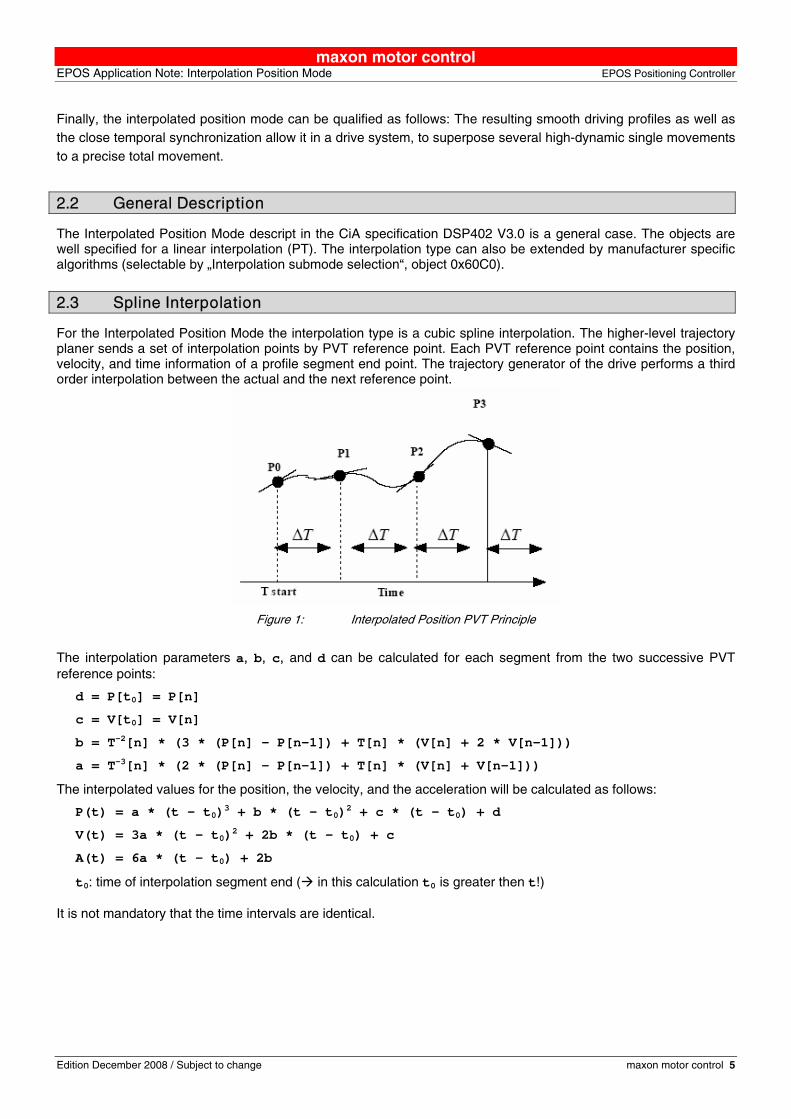
For the Interpolated Position Mode the interpolation type is a cubic spline interpolation. The higher-level trajectory planer sends a set of interpolation points by PVT reference point. Each PVT reference point contains the position, velocity, and time information of a profile segment end point. The trajectory generator of the drive performs a third order interpolation between the actual and the next reference point.
Figure 1: Interpolated Position PVT Principle
The interpolation parameters a, b, c, and d can be calculated for each segment from the two successive PVT reference points:
d = P[t0] = P[n]
c = V[t0] = V[n]
b = T-2[n] * (3 * (P[n] – P[n-1]) + T[n] * (V[n] + 2 * V[n-1]))
a = T-3[n] * (2 * (P[n] – P[n-1]) + T[n] * (V[n] + V[n-1]))
The interpolated values for the position, the velocity, and the acceleration will be calculated as follows:
P(t) = a * (t – t0)3 + b * (t – t0)2 + c * (t – t0) + d
V(t) = 3a * (t – t0)2 + 2b * (t – t0) + c
A(t) = 6a * (t – t0) + 2b
t0: time of interpolation segment end ( in this calculation t0 is greater then t!) It is not mandatory that the time intervals are identical.

maxon motor control EPOS Positioning Controller EPOS Application Note: Interpolation Position Mode
6 maxon motor control Edition December 2008 / Subject to change
2.4 SYNC-Time stamp mechanism
The SYNC-Time stamp mechanism can be used to synchronize the motion clock of the drive with a master clock in the network.
DeviceMaster Device
Time (TimeOfDay)
SYNC
HR_TimeStamp(Tm1)
SYNC
HR_TimeStamp(Tm2)
Tm = 0
Td1
Tm1
Tm2
Td2
Td = 0
Td = Td + Tm1 – Td1
Td = Td + Tm2 – Td2
Figure 2: Clock synchronization
The synchronization method is similar to IEEE 1588 and uses the CANopen DSP301 SYNC Service (COB-Id 0x80) and the High Resolution Time Stamp Object (0x1013). The SYNC Frame will be transmitted periodically by the SYNC master and the exact transmitting time (Tm1) should be stored in the master by latching an internal 1us timer. The reception time (Td1) of the SYNC message will be stored by latching the device internal motion clock timer. As following up the measured transmitting time (Tm1) will be send to the drive with the High Resolution Time Stamp. The device adjusts then its internal motion clock time in relation to the time latched in the last SYNC. By sending a CANopen DSP301 TIME Service (default COB-Id 0x100 or defined by Object 0x1012) the device internal motion clock timer can be reset to zero.

maxon motor control EPOS Application Note: Interpolation Position Mode EPOS Positioning Controller
Edition December 2008 / Subject to change maxon motor control 7
3 IPM Implementation by Maxon The Interpolated Position Mode is implemented in the EPOS2 as an additional operational mode (operation mode 7 as specified in DSP 402 V3.0).
Interpolation_data_record(0x20C1) [position units] Input
Buffer
software_position_limit(0x607D)
[velocity units]
maximal_profile_velocity(0x607F)
Interpolated PositionTrajectory Generator
position_demand_value*
[inc]
statusword(0x6041)
velocity_demand_value*
[inc/ms]
acceleration_demand_value*
[inc/ms ]2
Multiplier
max_acceleration(0x60C5)
position*
[inc]
[inc/ms ]2
controlword(0x6040)
position* [inc]
[inc/ms]
LimitFunction
Interpolationstatus(0x20C4)
[acceleration units]
velocity* [inc/ms]
velocity*Multiplier[inc/ms]
Interpolation_submode_selection(0x60C0)
Interpolation_data_configuration(0x60C4)
Figure 3: Interpolation Controller
3.1 Interpolated position data buffer
The PVT reference points will be sent in a manufacturer specific 64bit data record of a complex data structure to a FIFO object.
3.1.1 Definition of complex data structure 0x0040
MSB LSB Time (unsigned8) Velocity (signed24) Position (signed32)
Table 1: IPM data buffer entry structure
maxon motor control EPOS Positioning Controller EPOS Application Note: Interpolation Position Mode
8 maxon motor control Edition December 2008 / Subject to change
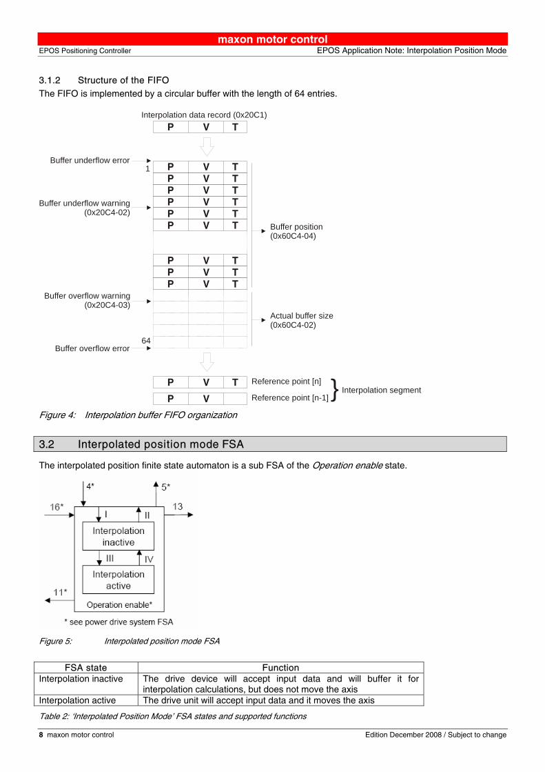
3.1.2 Structure of the FIFO
The FIFO is implemented by a circular buffer with the length of 64 entries.
TVPTVPTVPTVPTVPTVP
TVPTVP
TVP
TVP
TVP
1
64
Buffer underflow error
Buffer underflow warning(0x20C4-02)
Buffer overflow warning(0x20C4-03)
Buffer overflow error
Buffer position(0x60C4-04)
Actual buffer size(0x60C4-02)
Interpolation data record (0x20C1)
Reference point [n]
Reference point [n-1]VPInterpolation segment}
Figure 4: Interpolation buffer FIFO organization
3.2 Interpolated position mode FSA
The interpolated position finite state automaton is a sub FSA of the Operation enable state.
Figure 5: Interpolated position mode FSA
FSA state Function
Interpolation inactive The drive device will accept input data and will buffer it for interpolation calculations, but does not move the axis
Interpolation active The drive unit will accept input data and it moves the axis
Table 2: ‘Interpolated Position Mode’ FSA states and supported functions
maxon motor control EPOS Application Note: Interpolation Position Mode EPOS Positioning Controller
Edition December 2008 / Subject to change maxon motor control 9
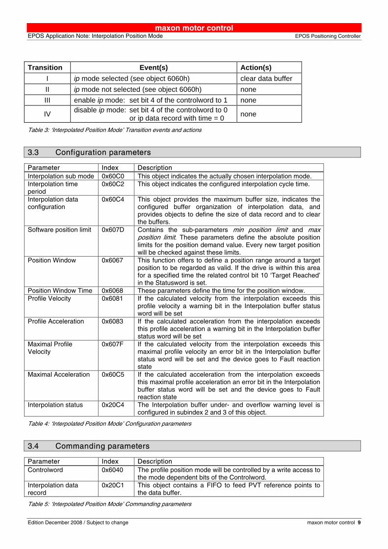
Transition Event(s) Action(s)
I ip mode selected (see object 6060h) clear data buffer II ip mode not selected (see object 6060h) none III enable ip mode: set bit 4 of the controlword to 1 none
IV disable ip mode: set bit 4 of the controlword to 0 or ip data record with time = 0 none
Table 3: ‘Interpolated Position Mode’ Transition events and actions
3.3 Configuration parameters
Parameter Index Description Interpolation sub mode 0x60C0 This object indicates the actually chosen interpolation mode. Interpolation time period
0x60C2 This object indicates the configured interpolation cycle time.
Interpolation data configuration
0x60C4 This object provides the maximum buffer size, indicates the configured buffer organization of interpolation data, and provides objects to define the size of data record and to clear the buffers.
Software position limit 0x607D Contains the sub-parameters min position limit and max position limit. These parameters define the absolute position limits for the position demand value. Every new target position will be checked against these limits.
Position Window 0x6067 This function offers to define a position range around a target position to be regarded as valid. If the drive is within this area for a specified time the related control bit 10 ‘Target Reached’ in the Statusword is set.
Position Window Time 0x6068 These parameters define the time for the position window. Profile Velocity 0x6081 If the calculated velocity from the interpolation exceeds this
profile velocity a warning bit in the Interpolation buffer status word will be set
Profile Acceleration 0x6083 If the calculated acceleration from the interpolation exceeds this profile acceleration a warning bit in the Interpolation buffer status word will be set
Maximal Profile Velocity
0x607F If the calculated velocity from the interpolation exceeds this maximal profile velocity an error bit in the Interpolation buffer status word will be set and the device goes to Fault reaction state
Maximal Acceleration 0x60C5 If the calculated acceleration from the interpolation exceeds this maximal profile acceleration an error bit in the Interpolation buffer status word will be set and the device goes to Fault reaction state
Interpolation status 0x20C4 The Interpolation buffer under- and overflow warning level is configured in subindex 2 and 3 of this object.
Table 4: ‘Interpolated Position Mode’ Configuration parameters
3.4 Commanding parameters
Parameter Index Description Controlword 0x6040 The profile position mode will be controlled by a write access to
the mode dependent bits of the Controlword. Interpolation data record
0x20C1 This object contains a FIFO to feed PVT reference points to the data buffer.
Table 5: ‘Interpolated Position Mode’ Commanding parameters

maxon motor control EPOS Positioning Controller EPOS Application Note: Interpolation Position Mode
10 maxon motor control Edition December 2008 / Subject to change
3.4.1 Controlword (Interpolated Position Mode specific bits)
The Controlword is a combination of operation mode dependent and mode independent bits. The mode independent bits are described in the EPOS2 Firmware Specification chapter 8.1.3 and 14.67 and the control bits of the IPM are described below. Bits 15 - 9 Bit 8 Bit 7 Bit 6 - 5 Bit 4 Bits 3 - 0 (see FwSpec) Halt (see FwSpec) reserved (0) Enable ip mode (see FwSpec)
Table 6: ‘Interpolated Position Mode’ specific Controlword
Name Value Description
0 Interpolated position mode inactive Enable ip mode 1 Interpolated position mode active 0 Execute instruction of Bit4 Halt 1 Stop axis with profile deceleration
Table 7: ‘Interpolated Position Mode’ bits of the Controlword
3.5 Output parameters
Parameter Index Description Interpolation status 0x20C4 The statusword of the interpolation mode is placed in subindex
1 of this object. Statusword 0x6041 The interpolated position mode state can be observed by the
specific bits of Statusword. Position demand value 0x6062 The position demand value is the output of the trajectory
generator. This value is the input for the position control function.
Table 8: ‘Interpolated Position Mode’ Output parameters
3.5.1 Statusword (Interpolated Position Mode specific bits) The Statusword is a combination of operation mode dependent and mode independent bits. The mode independent bits are described in the EPOS2 Firmware Specification chapter 8.1.1 and 14.68 and the status bits of the IPM are described below.
Bits 15, 14 Bit 13 Bit 12 Bit 11 Bit 10 Bits 9 - 0 (see FwSpec) reserved ip mode active (see FwSpec) Target reached (see FwSpec)
Table 9: ‘Interpolated Position Mode’ specific Statusword
Name Value Description
0 Halt = 0: Target position not (yet) reached Halt = 1: Axle decelerates
Target reached
1 Halt = 0: Target position reached Halt = 1: Velocity of axle is 0
0 ip mode inactive ip mode active 1 ip mode active
Table 10: ‘Interpolated Position Mode’ bits of the Statusword

maxon motor control EPOS Application Note: Interpolation Position Mode EPOS Positioning Controller
Edition December 2008 / Subject to change maxon motor control 11
3.6 Detailed Object description
3.6.1 COB-ID Time Stamp Object
Name COB-IB Time Stamp Object
Index 0x1012
Subindex 0x00
Type UNSIGNED32
Access RW
Default Value 0x00000100
Value range 0x00000100 0x00000100
PDO Mapping No
Description This object defines the COB-ID of the Time-Stamp Object (TIME). On the EPOS2 this value is constant.
3.6.2 High Resolution Time Stamp
Name High Resolution Time Stamp
Index 0x1013
Subindex 0x00
Type UNSIGNED32
Access RW
Default Value -
Value range - -
PDO Mapping Yes
Description This object contains the timestamp of the last received SYNC Object [1us]. The resolution of the device internal motion clock timer depends on the selected CAN bitrate (bit time) e.g. 1us at 1Mbit/s. After a write access to this object the EPOS2 calculates the difference between the received timestamp and the internal latched timestamp of the SYNC Object. This time difference is used as correction for the IPM time calculations.
3.6.3 Interpolation data record
Name Interpolation data record
Index 0x20C1
Subindex 0x00
Type complex data structure 0x0040
Access WO
Default Value -
Value range - -
PDO Mapping Yes Description This object sets PVT reference points in the interpolated position mode in the cubic spline interpolation sub-mode. The position is given absolute in [Position units] (typically [qc]), the velocity is given in [Velocity units] (typically [rpm]), and the time is given in [ms]. The object structure is defined in Definition of complex data structure 0x0040
maxon motor control EPOS Positioning Controller EPOS Application Note: Interpolation Position Mode
12 maxon motor control Edition December 2008 / Subject to change
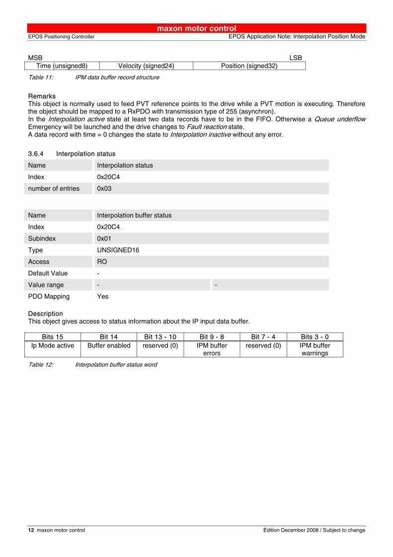
MSB LSB Time (unsigned8) Velocity (signed24) Position (signed32)
Table 11: IPM data buffer record structure
Remarks This object is normally used to feed PVT reference points to the drive while a PVT motion is executing. Therefore the object should be mapped to a RxPDO with transmission type of 255 (asynchron). In the Interpolation active state at least two data records have to be in the FIFO. Otherwise a Queue underflow Emergency will be launched and the drive changes to Fault reaction state. A data record with time = 0 changes the state to Interpolation inactive without any error.
3.6.4 Interpolation status
Name Interpolation status
Index 0x20C4
number of entries 0x03
Name Interpolation buffer status
Index 0x20C4
Subindex 0x01
Type UNSIGNED16
Access RO
Default Value -
Value range - -
PDO Mapping Yes
Description This object gives access to status information about the IP input data buffer.
Bits 15 Bit 14 Bit 13 - 10 Bit 9 - 8 Bit 7 - 4 Bits 3 - 0 Ip Mode active Buffer enabled reserved (0) IPM buffer
errors reserved (0) IPM buffer
warnings
Table 12: Interpolation buffer status word

maxon motor control EPOS Application Note: Interpolation Position Mode EPOS Positioning Controller
Edition December 2008 / Subject to change maxon motor control 13
Name Bit Value Description 0 No buffer underflow warning Underflow Warning 0 1 Buffer underflow warning level (0x20C4-2) is reached 0 No buffer overflow warning Overflow Warning 1 1 Buffer overflow warning level (0x20C4-3) is reached 0 No profile velocity violation detected Velocity Warning 2 1 IPM velocity greater then profile velocity (0x6081) detected 0 No profile acceleration violation detected Acceleration
Warning 3
1 IPM acceleration greater then profile acceleration (0x6083) detected
0 No buffer underflow error Underflow Error 8 1 Buffer underflow error ( trajectory abort) 0 No buffer overflow error Overflow Error 9 1 Buffer overflow error ( trajectory abort) 0 No maximal profile velocity violation detected Velocity Error 2 1 IPM velocity greater then maximal profile velocity (0x607F)
detected ( trajectory abort) 0 No maximal profile acceleration violation detected Acceleration Error 3 1 IPM acceleration greater then maximal profile acceleration
(0x60C5) detected ( trajectory abort) 0 Disabled access to the input buffer Buffer enabled 14 1 Access to the input buffer enabled 0 ip mode inactive (same as bit 12 in statusword) Ip Mode active 15 1 ip mode active
Table 13: Interpolation buffer status bits
Name Interpolation buffer underflow warning
Index 0x20C4
Subindex 0x02
Type UNSIGNED16
Access RW
Default Value 4
Value range 0 63
PDO Mapping No Description This object gives lower signalization level of the data input FIFO. If the filling level is below this border the warning flag (bit 0) in the Interpolation buffer status will be set.
Name Interpolation buffer overflow warning
Index 0x20C4
Subindex 0x03
Type UNSIGNED16
Access RW
Default Value 60
Value range 1 64
PDO Mapping No
Description This object gives the higher signalization level of the data input FIFO. If the filling level is above this border the warning flag (bit 1) in the Interpolation buffer status will be set.
maxon motor control EPOS Positioning Controller EPOS Application Note: Interpolation Position Mode
14 maxon motor control Edition December 2008 / Subject to change
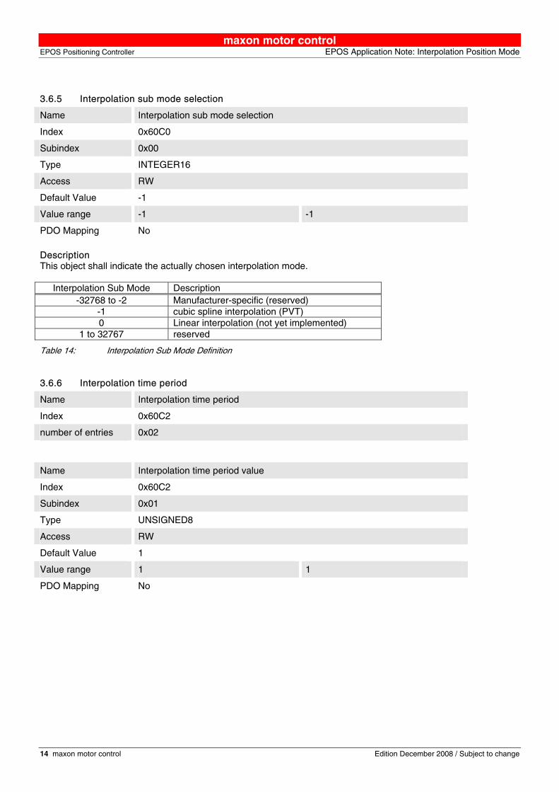
3.6.5 Interpolation sub mode selection
Name Interpolation sub mode selection
Index 0x60C0
Subindex 0x00
Type INTEGER16
Access RW
Default Value -1
Value range -1 -1
PDO Mapping No
Description This object shall indicate the actually chosen interpolation mode.
Interpolation Sub Mode Description -32768 to -2 Manufacturer-specific (reserved)
-1 cubic spline interpolation (PVT) 0 Linear interpolation (not yet implemented)
1 to 32767 reserved
Table 14: Interpolation Sub Mode Definition
3.6.6 Interpolation time period
Name Interpolation time period
Index 0x60C2
number of entries 0x02
Name Interpolation time period value
Index 0x60C2
Subindex 0x01
Type UNSIGNED8
Access RW
Default Value 1
Value range 1 1
PDO Mapping No
maxon motor control EPOS Application Note: Interpolation Position Mode EPOS Positioning Controller
Edition December 2008 / Subject to change maxon motor control 15
Name Interpolation time index
Index 0x60C2
Subindex 0x01
Type INTEGER8
Access RW
Default Value -3
Value range -3 -3
PDO Mapping No
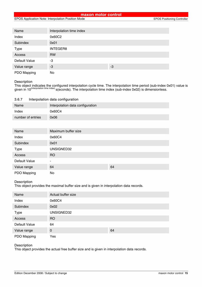
Description This object indicates the configured interpolation cycle time. The interpolation time period (sub-index 0x01) value is given in 10(interpolation time index) s(econds). The interpolation time index (sub-index 0x02) is dimensionless.
3.6.7 Interpolation data configuration
Name Interpolation data configuration
Index 0x60C4
number of entries 0x06
Name Maximum buffer size
Index 0x60C4
Subindex 0x01
Type UNSIGNED32
Access RO
Default Value -
Value range 64 64
PDO Mapping No
Description This object provides the maximal buffer size and is given in interpolation data records. Name Actual buffer size
Index 0x60C4
Subindex 0x02
Type UNSIGNED32
Access RO
Default Value 64
Value range 0 64
PDO Mapping Yes
Description This object provides the actual free buffer size and is given in interpolation data records.
maxon motor control EPOS Positioning Controller EPOS Application Note: Interpolation Position Mode
16 maxon motor control Edition December 2008 / Subject to change
Name Buffer organisation
Index 0x60C4
Subindex 0x03
Type UNSIGNED8
Access RW
Default Value 0
Value range 0 0
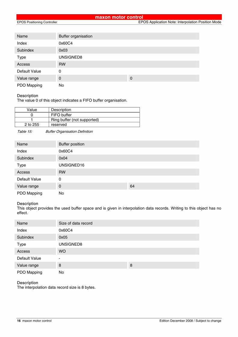
PDO Mapping No Description The value 0 of this object indicates a FIFO buffer organisation.
Value Description 0 FIFO buffer 1 Ring buffer (not supported)
2 to 255 reserved
Table 15: Buffer Organisation Definition
Name Buffer position
Index 0x60C4
Subindex 0x04
Type UNSIGNED16
Access RW
Default Value 0
Value range 0 64
PDO Mapping No Description This object provides the used buffer space and is given in interpolation data records. Writing to this object has no effect.
Name Size of data record
Index 0x60C4
Subindex 0x05
Type UNSIGNED8
Access WO
Default Value -
Value range 8 8
PDO Mapping No
Description The interpolation data record size is 8 bytes.
maxon motor control EPOS Application Note: Interpolation Position Mode EPOS Positioning Controller
Edition December 2008 / Subject to change maxon motor control 17
Name Buffer clear
Index 0x60C4
Subindex 0x06
Type UNSIGNED8
Access WO
Default Value 0
Value range 0 1
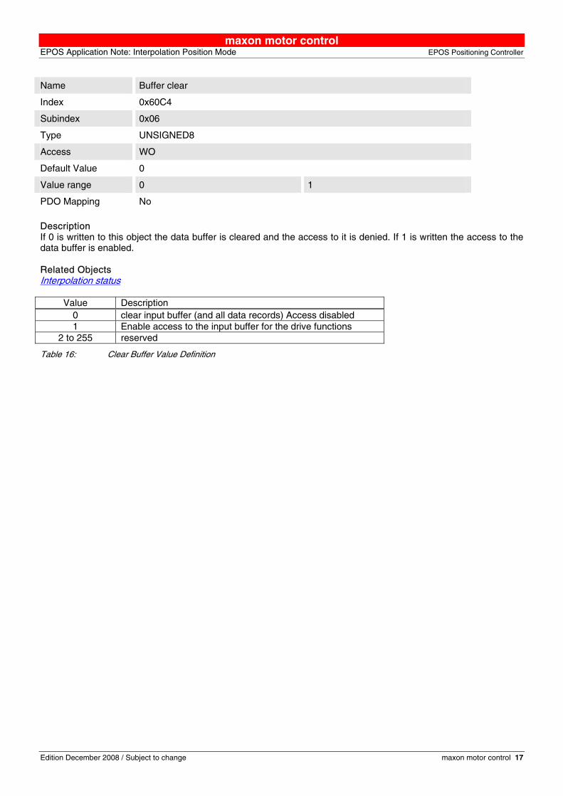
PDO Mapping No Description If 0 is written to this object the data buffer is cleared and the access to it is denied. If 1 is written the access to the data buffer is enabled. Related Objects Interpolation status
Value Description 0 clear input buffer (and all data records) Access disabled 1 Enable access to the input buffer for the drive functions
2 to 255 reserved
Table 16: Clear Buffer Value Definition
maxon motor control EPOS Positioning Controller EPOS Application Note: Interpolation Position Mode
18 maxon motor control Edition December 2008 / Subject to change
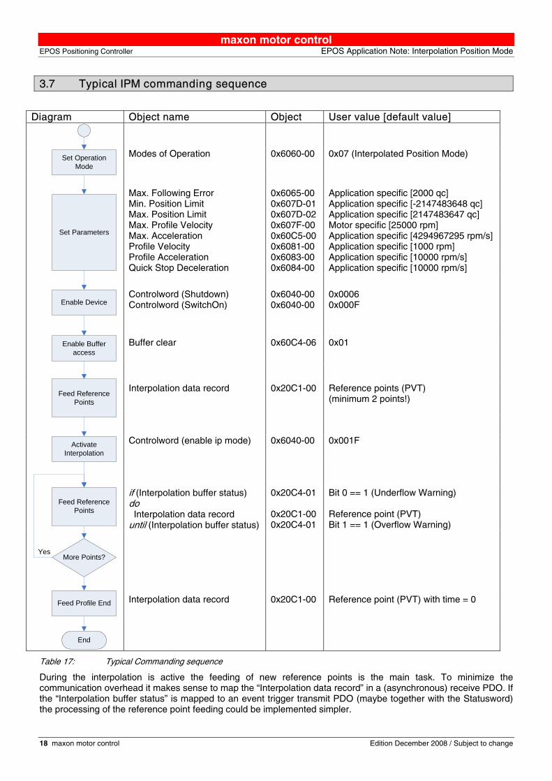
3.7 Typical IPM commanding sequence
Diagram Object name Object User value [default value]
Modes of Operation 0x6060-00 0x07 (Interpolated Position Mode)
Max. Following Error Min. Position Limit Max. Position Limit Max. Profile Velocity Max. Acceleration Profile Velocity Profile Acceleration Quick Stop Deceleration
0x6065-00 0x607D-01 0x607D-02 0x607F-00 0x60C5-00 0x6081-00 0x6083-00 0x6084-00
Application specific [2000 qc] Application specific [-2147483648 qc] Application specific [2147483647 qc] Motor specific [25000 rpm] Application specific [4294967295 rpm/s] Application specific [1000 rpm] Application specific [10000 rpm/s] Application specific [10000 rpm/s]
Controlword (Shutdown) Controlword (SwitchOn)
0x6040-00 0x6040-00
0x0006 0x000F
Buffer clear 0x60C4-06 0x01
Interpolation data record 0x20C1-00 Reference points (PVT) (minimum 2 points!)
Controlword (enable ip mode) 0x6040-00 0x001F
if (Interpolation buffer status) do Interpolation data record until (Interpolation buffer status)
0x20C4-01 0x20C1-00 0x20C4-01
Bit 0 == 1 (Underflow Warning) Reference point (PVT) Bit 1 == 1 (Overflow Warning)
Interpolation data record 0x20C1-00 Reference point (PVT) with time = 0
Set Operation Mode
Set Parameters
Enable Device
Enable Buffer access
Feed Reference Points
Activate Interpolation
Feed Reference Points
End
More Points?
Feed Profile End
Yes
Table 17: Typical Commanding sequence
During the interpolation is active the feeding of new reference points is the main task. To minimize the communication overhead it makes sense to map the “Interpolation data record” in a (asynchronous) receive PDO. If the “Interpolation buffer status” is mapped to an event trigger transmit PDO (maybe together with the Statusword) the processing of the reference point feeding could be implemented simpler.

maxon motor control EPOS Application Note: Interpolation Position Mode EPOS Positioning Controller
Edition December 2008 / Subject to change maxon motor control 19
Use CANopen Wizard in Epos Studio for configuration the PDO mapping. Step 1: Select "Restore Default COB-IDs" in Step 4 of CANopen Wizard Step 2: Set "PDO is valid" and transmission type to "Asynchronous" in Receive PDO1 Parameter
Step 3: Delete all mapped Object in "Change Mapping" window Step 4: Add "Interpolation Data Record" to Receive PDO1

maxon motor control EPOS Positioning Controller EPOS Application Note: Interpolation Position Mode
20 maxon motor control Edition December 2008 / Subject to change
Step 5: Set "PDO is valid", transmission type to "Asynchronous" and "inhibit time" to e.g. 5.0 ms
Step 6: Delete all mapped Object in "Change Mapping" window Step 7: Add "Interpolation Buffer Status" and "StatusWord" to Transmit PDO1
Step 8: go on to finish to CANopen Wizard Motion Synchronisation The interpolated position mode enables the synchronized motion of multiple axes. The motions of several slave axes can be synchronized if they all run in IPM, and they all have the same time. In order to start several axes synchronously, map the controlword to a synchronous RPDO, and then use the mapped controlword to enable interpolation for all axes. Nothing will happen until the next SYNC. Then, all drives will enable interpolated motion at once, setting the SYNC arrival time as the “zero” time of the path specification. If the axes have been synchronized by the SYNC-Time stamp mechanism, the moving axes should be relatively synchronized to the precision of microseconds. If the CAN (SYNC) master is not able to produce the high resolution time stamp it is also possible to use one EPOS2 as clock master. For this the “High Resolution Time Stamp” object (0x1013) should be mapped to a synchronous transmit PDO on the clock master EPOS2. The other EPOS2 in the system has to be configured as

maxon motor control EPOS Application Note: Interpolation Position Mode EPOS Positioning Controller
Edition December 2008 / Subject to change maxon motor control 21
clock slaves. On this devices the “High Resolution Time Stamp” object is mapped to an asynchrony receive PDO with the very same COB-ID as the transmit PDO on the clock master. Note: The resolution of the EPOS internal microsecond timer depends on the CAN bitrate due to a CAN controller
internal hardware counter is used as timing reference. This hardware counter will be incremented by the bit time.
3.8 Interruption of interpolation mode in case of an error
If a currently running interpolation (index 0x20C4, subindex 0x03 "interpolation status" bit 15 "ip mode active" set) will be interrupted by the occurance of an error, the EPOS2 reacts as specified for the certain error (i.e. disabling the controller and changing to the state switch on disabled). The interpolation can only be restarted by a re-synchronisation, because the state Operation enable has to be entered again, whereby the bit "ip mode active" will be cleared.