Embed Size (px)
Citation preview

EQT MIDSTREAM DESIGN AND CONSTRUCTION MANUAL CONSTRUCTION STANDARD CORROSION CONTROL 10.4 CORROSION CONTROL FOR CONSTRUCTION Total Pages: 22
Corrosion Control for Const.doc Page 1 Revision / Save Date: 3/14/17
Table of Contents
Scope ............................................................................................................................................................................ 3 References ................................................................................................................................................................... 3
Governmental ........................................................................................................................................................ 3 EQT Midstream Publications ................................................................................................................................. 3 Industry Standards ................................................................................................................................................. 4 Miscellaneous References ..................................................................................................................................... 5
Glossary ....................................................................................................................................................................... 5 1 Above Ground Coatings...................................................................................................................................... 6
Table 1: Color Scheme for Compressor Facilities ................................................................................................. 7 1.1 Above Ground Surface Preparation ............................................................................................................. 7 1.2 Above Ground Coating Application .............................................................................................................. 8 1.3 Existing Painted Piping Top Coat ................................................................................................................. 9 1.4 Inspection of Above Grade applications ....................................................................................................... 9
1.4.1 Visual Inspection .............................................................................................................................. 9 1.5 Transitional Corrosion Protection ............................................................................................................... 10
2 Below Ground Coatings .................................................................................................................................... 10 2.1 Mill-Applied Coating ................................................................................................................................... 10
2.1.1 Fusion Bond Epoxies ..................................................................................................................... 10 2.1.2 Extruded Coating ............................................................................................................................ 11 2.1.3 Dual Coat FBE System .................................................................................................................. 11 2.1.4 FBE / Powercrete Coating System ................................................................................................. 11
2.2 Handling Mill-Coated Pipe .......................................................................................................................... 11 2.3 Field Applied Coatings ............................................................................................................................... 11
2.3.1 Two-Part Epoxies ........................................................................................................................... 12 2.3.2 Wax Tape ....................................................................................................................................... 12 2.3.3 Shrink Sleeves ............................................................................................................................... 12
2.4 Below Ground Surface Preparation ........................................................................................................... 12 2.4.1 Surface Preparation- Two-Part Epoxy ........................................................................................... 12 2.4.2 Surface Preparation- Wax Tape ..................................................................................................... 13 2.4.3 Surface Preparation- Shrink Sleeves ............................................................................................. 13
2.5 Below Ground Coating Application ............................................................................................................ 13 2.6 Safety/Housekeeping ................................................................................................................................. 14 2.7 Inspection of Below Grade Applications ..................................................................................................... 14
2.7.1 Visual Inspection ............................................................................................................................ 14 2.7.2 Holiday Detection and Repair......................................................................................................... 14 Table 1: Voltage Setting for Holiday Detectors .......................................................................................... 15

EQT MIDSTREAM DESIGN AND CONSTRUCTION MANUAL CONSTRUCTION STANDARD CORROSION CONTROL 10.4 CORROSION CONTROL FOR CONSTRUCTION Total Pages: 22
Corrosion Control for Const.doc Page 2 Revision / Save Date: 3/14/17
3 Cathodic Protection System Installation ......................................................................................................... 16 3.1 Galvanic Systems ....................................................................................................................................... 16
3.1.1 Galvanic System Installation .......................................................................................................... 17 3.2 Impressed Current Systems ....................................................................................................................... 17
3.2.1 Impressed Current System Installation .......................................................................................... 17
4 Test Station Installation .................................................................................................................................... 18 5 Corrosion Surveys ............................................................................................................................................. 19 6 AC Mitigation Facilities Installation ................................................................................................................. 20
6.1 Zinc Ribbon ................................................................................................................................................ 20 6.2 Solid-State Decoupler ................................................................................................................................ 20 6.3 Gradient Control Mats ................................................................................................................................ 20
Version Control .......................................................................................................................................................... 22
EQT MIDSTREAM DESIGN AND CONSTRUCTION MANUAL CONSTRUCTION STANDARD CORROSION CONTROL 10.4 CORROSION CONTROL FOR CONSTRUCTION Total Pages: 22
Corrosion Control for Const.doc Page 3 Revision / Save Date: 3/14/17
Scope
• This Corrosion Control Construction Standard is intended to set forth the requirements of EQT Midstream; hereafter known throughout this document as ‘Company’, for the installation of corrosion control systems including, but not limited to, coatings, cathodic protection, and interference mitigation.
• The Project Specific Scope of Work or drawings, as provided to the Contractor(s) for each specific project, shall govern in the case of any conflicting statements discovered or encountered between this manual and the Scope of Work or project drawings. Any questions regarding conflicts or omissions shall be directed to the authorized company representative, hereafter known throughout this document as the ‘Company’. The Company representative will refer questions to the responsible Company department.
• This standard has been written to apply to all pipelines and facilities with the understanding that further restrictions and regulations will need to be followed for specific pipelines and facilities, and further documentation and specifications will be provided for those pipeline and facility projects within the Contractor(s) scope of work.
• All codes and standards referenced in this specification, as they may apply, shall be the current edition or the edition referenced.
References
Governmental
GOVERNMENT REGULATION REFERENCES
Code of Federal Regulations
• Title 49 CFR Part 192 ‘Transportation of Natural and Other Gas by Pipeline: Minimum Federal Safety Standards’, (PHMSA, DOT)
EQT Midstream Publications
EQT POLICY, STANDARDS, & PUBLICATIONS
Design and Construction Manual • 10.1 Facility Construction and Commissioning Standard
• 10.2 Pipeline Construction Standard
• 2.3 Approved Manufacturers List
• 11.1 Aboveground External Corrosion Protection
• 11.2 Underground External Corrosion Protection
• 11.4 Cathodic Protection Facility Design
• 11.5 Internal Corrosion Design
• 11.6 Current Interference Mitigation
• 11.7 Test Station Design
• 13.6 Corrosion Standard Drawings

EQT MIDSTREAM DESIGN AND CONSTRUCTION MANUAL CONSTRUCTION STANDARD CORROSION CONTROL 10.4 CORROSION CONTROL FOR CONSTRUCTION Total Pages: 22
Corrosion Control for Const.doc Page 4 Revision / Save Date: 3/14/17
Industry Standards
INDUSTRY STANDARDS
*Latest edition incorporated by reference in Title 49 CFR 192
• NACE SP0169, Control of External Corrosion on Underground or Submerged Metallic Piping Systems
• NACE SP0177, Mitigation of Alternating Current and Lightning Effects on Metallic Structures and Corrosion Control Systems
• NACE SP0188, Discontinuity (Holiday) Testing of New Protective Coatings on Conductive Substrates
• NACE SP0207, Performing Close Interval Potential Surveys and DC Surface Potential Gradient Surveys on Buried or Submerged Metallic Pipelines
• NACE No. 3/SSPC-SP 6, Commercial Blast Cleaning
• NACE No. 4/SSPC-SP 7, Brush-Off Blast Cleaning
• NACE No. 5/SSPC-SP 12, Surface Preparation and Cleaning of Steel and Other Hard Materials by High- and Ultra High- Pressure Water Jetting Prior to Recoating
• NACE WJ-1/SSPC-SP WJ-1, Waterjet Cleaning of Metals – Clean to Bare Substrate (WJ-1)
• NFPA-70, National Electric Code
• SSPC-PA 2, Procedure for Determining Conformance to Dry Coating Thickness Requirements
• SSPC-SP 1, Solvent Cleaning
• SSPC-SP 2, Hand Tool Cleaning
• SSPC-SP 3, Power Tool Cleaning
• SSPC-SP 11, Power Tool Cleaning to Bare Metal SSPC-VIS 1, Guide and Reference Photographs for Steel Surfaces Prepared by Dry Abrasive Blast Cleaning
• SSPC-VIS 3, Guide and Reference Photographs for Steel Surfaces Prepared by Hand and Power Tool Cleaning
EQT MIDSTREAM DESIGN AND CONSTRUCTION MANUAL CONSTRUCTION STANDARD CORROSION CONTROL 10.4 CORROSION CONTROL FOR CONSTRUCTION Total Pages: 22
Corrosion Control for Const.doc Page 5 Revision / Save Date: 3/14/17
Miscellaneous References
REFERENCE
Daily Coating Form Daily Painting Form Jeep Daily Form Standard Operating Procedures
• MP 001.01 - Inspect Shorted Casing
• MP 001.02 - Clear or Repair Shorted Casing
• MP 002 - Apply Pipe Coating in the Field (Hot Application)
• MP 003 - Apply Pipe Coating in the Field (Cold Application)
• MP 005 - Measure Pipe-to-Soil Electrolyte Potential
• MP 006 - Measure Soil Resistivity
• MP 007 - Inspect Internal Corrosion with Coupons
• MP 008 - Install CP Electrical Isolation Devices
• MP 009 - Interference Current Testing
• MP 011 - Inspect Interference Bonds
• MP 012 - Inspect for Atmospheric Corrosion
• MP 013 - Inspect Pipeline When Exposed or After Maintenance
• MP 015 - Install or Replace Rectifier
• MP 016 Install or Replace Anodes
• MP 019 Install or Replace Test Station
• MP 094 Holiday Detection
• MP 102.01 Thermite Welding
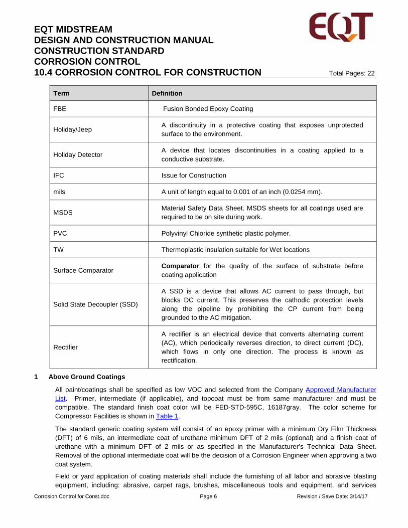
Glossary
Term Definition
AC Alternating Current
ARO Abrasion Resistant Overcoat. A sacrificial coating put on the outside of the cathodic protection coating to protect from damage.
AWG American Wire Gauge
DC Direct Current
DFT Dry Film Thickness of a Coating
EQT MIDSTREAM DESIGN AND CONSTRUCTION MANUAL CONSTRUCTION STANDARD CORROSION CONTROL 10.4 CORROSION CONTROL FOR CONSTRUCTION Total Pages: 22
Corrosion Control for Const.doc Page 6 Revision / Save Date: 3/14/17
Term Definition
FBE Fusion Bonded Epoxy Coating
Holiday/Jeep A discontinuity in a protective coating that exposes unprotected surface to the environment.
Holiday Detector A device that locates discontinuities in a coating applied to a conductive substrate.
IFC Issue for Construction
mils A unit of length equal to 0.001 of an inch (0.0254 mm).
MSDS Material Safety Data Sheet. MSDS sheets for all coatings used are required to be on site during work.
PVC Polyvinyl Chloride synthetic plastic polymer.
TW Thermoplastic insulation suitable for Wet locations
Surface Comparator Comparator for the quality of the surface of substrate before coating application
Solid State Decoupler (SSD)
A SSD is a device that allows AC current to pass through, but blocks DC current. This preserves the cathodic protection levels along the pipeline by prohibiting the CP current from being grounded to the AC mitigation.
Rectifier
A rectifier is an electrical device that converts alternating current (AC), which periodically reverses direction, to direct current (DC), which flows in only one direction. The process is known as rectification.
1 Above Ground Coatings
All paint/coatings shall be specified as low VOC and selected from the Company Approved Manufacturer List. Primer, intermediate (if applicable), and topcoat must be from same manufacturer and must be compatible. The standard finish coat color will be FED-STD-595C, 16187gray. The color scheme for Compressor Facilities is shown in Table 1.
The standard generic coating system will consist of an epoxy primer with a minimum Dry Film Thickness (DFT) of 6 mils, an intermediate coat of urethane minimum DFT of 2 mils (optional) and a finish coat of urethane with a minimum DFT of 2 mils or as specified in the Manufacturer’s Technical Data Sheet. Removal of the optional intermediate coat will be the decision of a Corrosion Engineer when approving a two coat system.
Field or yard application of coating materials shall include the furnishing of all labor and abrasive blasting equipment, including: abrasive, carpet rags, brushes, miscellaneous tools and equipment, and services
EQT MIDSTREAM DESIGN AND CONSTRUCTION MANUAL CONSTRUCTION STANDARD CORROSION CONTROL 10.4 CORROSION CONTROL FOR CONSTRUCTION Total Pages: 22
Corrosion Control for Const.doc Page 7 Revision / Save Date: 3/14/17
necessary to ensure all applicable codes are met. To avoid all possible confusion, Contractor shall become thoroughly familiar with all provisions thereof.
Contractor shall understand that all materials and appliances installed throughout buildings and facilities which require painting shall be painted upon completion of the erection work. Galvanized metal, aluminum and concrete shall not be painted or coated unless required by regulation or specified by Company's project representative. This specification does not relieve the Contractor of the responsibility of maintaining all code requirements.
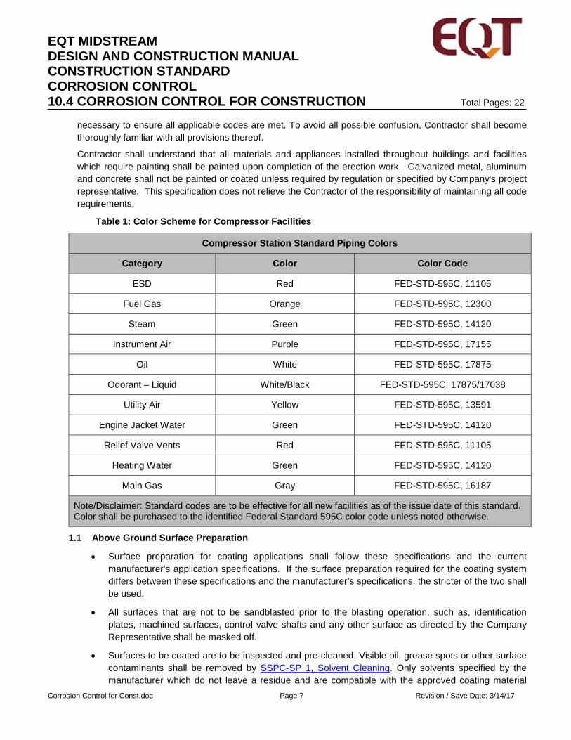
Table 1: Color Scheme for Compressor Facilities
Compressor Station Standard Piping Colors
Category Color Color Code
ESD Red FED-STD-595C, 11105
Fuel Gas Orange FED-STD-595C, 12300
Steam Green FED-STD-595C, 14120
Instrument Air Purple FED-STD-595C, 17155
Oil White FED-STD-595C, 17875
Odorant – Liquid White/Black FED-STD-595C, 17875/17038
Utility Air Yellow FED-STD-595C, 13591
Engine Jacket Water Green FED-STD-595C, 14120
Relief Valve Vents Red FED-STD-595C, 11105
Heating Water Green FED-STD-595C, 14120
Main Gas Gray FED-STD-595C, 16187
Note/Disclaimer: Standard codes are to be effective for all new facilities as of the issue date of this standard. Color shall be purchased to the identified Federal Standard 595C color code unless noted otherwise.
1.1 Above Ground Surface Preparation
• Surface preparation for coating applications shall follow these specifications and the current manufacturer’s application specifications. If the surface preparation required for the coating system differs between these specifications and the manufacturer’s specifications, the stricter of the two shall be used.
• All surfaces that are not to be sandblasted prior to the blasting operation, such as, identification plates, machined surfaces, control valve shafts and any other surface as directed by the Company Representative shall be masked off.
• Surfaces to be coated are to be inspected and pre-cleaned. Visible oil, grease spots or other surface contaminants shall be removed by SSPC-SP 1, Solvent Cleaning. Only solvents specified by the manufacturer which do not leave a residue and are compatible with the approved coating material

EQT MIDSTREAM DESIGN AND CONSTRUCTION MANUAL CONSTRUCTION STANDARD CORROSION CONTROL 10.4 CORROSION CONTROL FOR CONSTRUCTION Total Pages: 22
Corrosion Control for Const.doc Page 8 Revision / Save Date: 3/14/17
are to be used.
• All steel surfaces will be checked for the presence of non-visible surface contaminates. If the surface does not meet an NV-2 based on SSPC-SP 12/ NACE No.5, the surface must be cleaned with Chlor*Rid and low pressure (3,000 psig) water blasted.
• All steel surfaces shall be free of all rough welds, sharp edges and weld splatter. Rough edges, rough welds and all weld spatter shall be removed by SSPC–SP 2 “Hand Tool Cleaning”, SSPC-SP 3 “Power Tool Cleaning” and / or SSPC-SP 11 “Power Tool Cleaning to Bare Metal.” SSPC-VIS 3 shall be used as a surface comparator.
• The surface temperature should be a minimum of 5 oF above the measured dew point with no surface moisture present.
• All surfaces shall be cleaned by sandblasting to a minimum level of cleanliness, SSPC-SP 6, Commercial Blast Clean. All blast cleaned surfaces shall be inspected by the Company Inspector prior to the application of the primer coat.
• The applicator shall check the surface profile depth by using a surface profiling gauge such as the Press-O-Film Gauge.
• Any surface that develops flash rust shall be sweep blasted before coating application.
• All sandblasted surfaces shall be primed the same day. If not, the surface will be re-cleaned by sandblasting to a minimum level of cleanliness, SSPC-SP 6, Commercial Blast Clean the day of the application of the primer coat.
1.2 Above Ground Coating Application
Prior to the application of any coating, the Company Representative will review with the qualified Painter, the Product Technical Data Sheet for the following issues:
• Application equipment
• Air pressure requirements
• Thinning requirements
• Temperature and dew point considerations
• Mixing procedures
• Required Wet Film and Dry Film thickness
• MSDS sheets for all coatings used (Required to be on site during work)
Application shall be made in strict accordance with the Manufacturer’s application specifications. All new coating materials (purchased within 4 weeks of application) will be delivered to the job site in unopened, clearly marked containers and verified by the Company Representative. No coating shall be applied when the relative humidity exceeds 80%, or when the surface temperature is less than 45 oF. No coating shall be applied outside of the manufacturer’s range for ambient conditions without specific written variance from the manufacturer.
The primer, intermediate (if applicable), and top coats will be of contrasting colors unless the coating system specifies two coats of the same paint.

EQT MIDSTREAM DESIGN AND CONSTRUCTION MANUAL CONSTRUCTION STANDARD CORROSION CONTROL 10.4 CORROSION CONTROL FOR CONSTRUCTION Total Pages: 22
Corrosion Control for Const.doc Page 9 Revision / Save Date: 3/14/17
The Company Representative will verify that storage, mixing, and thinning are done in compliance with the Manufacturer’s instructions.
Each coat shall be inspected for the proper dry film thickness per SSPC-PA 2, color, and appearance. Each coat shall be free from pinholes, runs, sags, overspray, Holidays, foreign debris, or any other signs of improper application.
The Paint Contractor shall make necessary repairs of coating defects prior to the application of the next coat.
A final coating inspection will be made prior to acceptance of the project. Where coating thickness falls below the specified minimum, as determined by the Company Representative, an additional topcoat will be applied within the time limits for recoat as prescribed in the Technical Data Sheet to achieve the total required thickness.
1.3 Existing Painted Piping Top Coat
The application of a top coat to existing piping, for the purpose of color change or fading, that has a good, sound coating requires verification of existing coating type, i.e., epoxy, urethane, etc. to determine the compatibility of the applied top coat. At a minimum, surface preparation will require a SSPC–SP 7/NACE No.4, “Brush-Off Blast” for the top coat to properly adhere.
Minor touch-up of existing coating should be done with the same paint as on the piping. For alkyd and acrylic coatings, alkyd enamel can be used. For epoxy coatings, touch-up should be done with an epoxy paint. For urethane top coats, touch-up should be done with a urethane paint.
CAUTION
Paint Compatibility
All attempts should be made to identify existing paint to ensure compatibility.
Removal of Epoxy/Urethane Coating from Thread Area on Bolts
NAPA aircraft stripper should be used to soften the coating for the easier removal of epoxy/urethane coating from thread area on bolts.
1.4 Inspection of Above Grade applications
1.4.1 Visual Inspection
The finished coating shall be smooth and free of runs, sags and cracks. The surface of the coating shall be no rougher than the base or substrate material.
Coating thickness shall be checked at ambient temperature with a calibrated thickness gauge. The thickness gauge shall be calibrated using a U.S. Bureau of Standards certified coating calibration standard at the beginning of the shift or if the gauge is mishandled. Thickness measurements will
NOTE
EQT MIDSTREAM DESIGN AND CONSTRUCTION MANUAL CONSTRUCTION STANDARD CORROSION CONTROL 10.4 CORROSION CONTROL FOR CONSTRUCTION Total Pages: 22
Corrosion Control for Const.doc Page 10 Revision / Save Date: 3/14/17
be made in accordance with SSPC-PA 2.
The application contractor will document these checks on the Daily Coating Form at least twice per day.
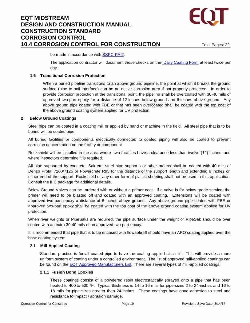
1.5 Transitional Corrosion Protection
When a buried pipeline transitions to an above ground pipeline, the point at which it breaks the ground surface (pipe to soil interface) can be an active corrosion area if not properly protected. In order to provide corrosion protection at the transitional point, the pipeline shall be overcoated with 30-40 mils of approved two-part epoxy for a distance of 12-inches below ground and 6-inches above ground. Any above ground pipe coated with FBE or that has been overcoated shall be coated with the top coat of the above ground coating system applied for UV protection.
2 Below Ground Coatings
Steel pipe can be coated in a coating mill or applied by hand or machine in the field. All steel pipe that is to be buried will be coated pipe.
All buried facilities or components electrically connected to coated piping will also be coated to prevent corrosion concentration on the facility or component.
Rockshield will be installed in the area where two facilities have a clearance less than twelve (12) inches, and where inspectors determine it is required.
All pipe supported by concrete, Sakrete, steel pipe supports or other means shall be coated with 40 mils of Denso Protal 7200/7125 or Powercrete R95 for the distance of the support length and extending 6 inches on either end of the support. Rockshield or any other form of plastic sheeting shall not be used in this application. Consult the IFC package for additional details.
Below Ground Valves can be ordered with or without a primer coat. If a valve is for below grade service, the primer will need to be blasted off and coated with an approved coating. Extensions will be coated with approved two-part epoxy a distance of 6-inches above ground. Any above ground pipe coated with FBE or approved two-part epoxy shall be coated with the top coat of the above ground coating system applied for UV protection.
When river weights or PipeSaks are required, the pipe surface under the weight or PipeSak should be over coated with an extra 30-40 mils of an approved two-part epoxy.
It is recommended that pipe that is to be encased with flowable fill should have an ARO coating applied over the base coating system.
2.1 Mill-Applied Coating
Standard practice is for all coated pipe to have the coating applied at a mill. This will provide a more uniform system of coating under a controlled environment. The list of approved mill-applied coatings can be found on the EQT Approved Manufacturers List. There are several types of mill-applied coatings.
2.1.1 Fusion Bond Epoxies
These coatings consist of a powdered resin electrostatically sprayed onto a pipe that has been heated to 400 to 500 oF. Typical thickness is 14 to 16 mils for pipe sizes 2 to 24-inches and 16 to 18 mils for pipe sizes greater than 24-inches. These coatings have good adhesion to steel and resistance to impact / abrasion damage.
EQT MIDSTREAM DESIGN AND CONSTRUCTION MANUAL CONSTRUCTION STANDARD CORROSION CONTROL 10.4 CORROSION CONTROL FOR CONSTRUCTION Total Pages: 22
Corrosion Control for Const.doc Page 11 Revision / Save Date: 3/14/17
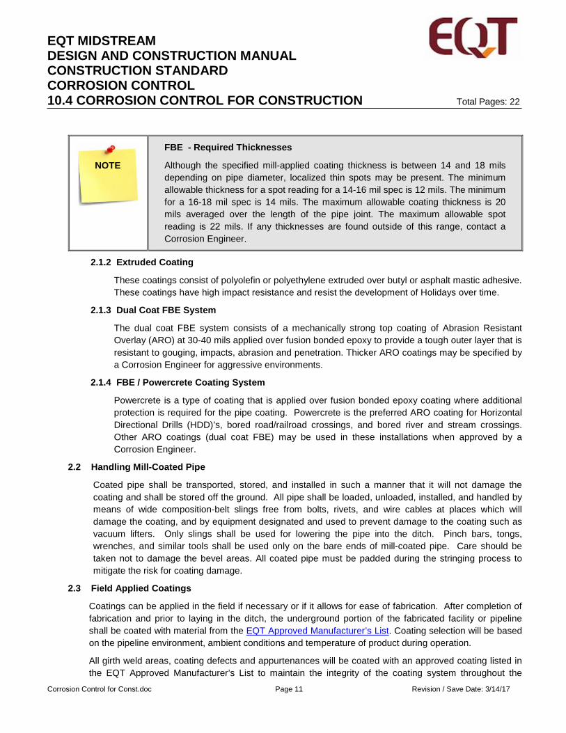
FBE - Required Thicknesses
Although the specified mill-applied coating thickness is between 14 and 18 mils depending on pipe diameter, localized thin spots may be present. The minimum allowable thickness for a spot reading for a 14-16 mil spec is 12 mils. The minimum for a 16-18 mil spec is 14 mils. The maximum allowable coating thickness is 20 mils averaged over the length of the pipe joint. The maximum allowable spot reading is 22 mils. If any thicknesses are found outside of this range, contact a Corrosion Engineer.
2.1.2 Extruded Coating
These coatings consist of polyolefin or polyethylene extruded over butyl or asphalt mastic adhesive. These coatings have high impact resistance and resist the development of Holidays over time.
2.1.3 Dual Coat FBE System
The dual coat FBE system consists of a mechanically strong top coating of Abrasion Resistant Overlay (ARO) at 30-40 mils applied over fusion bonded epoxy to provide a tough outer layer that is resistant to gouging, impacts, abrasion and penetration. Thicker ARO coatings may be specified by a Corrosion Engineer for aggressive environments.
2.1.4 FBE / Powercrete Coating System
Powercrete is a type of coating that is applied over fusion bonded epoxy coating where additional protection is required for the pipe coating. Powercrete is the preferred ARO coating for Horizontal Directional Drills (HDD)’s, bored road/railroad crossings, and bored river and stream crossings. Other ARO coatings (dual coat FBE) may be used in these installations when approved by a Corrosion Engineer.
2.2 Handling Mill-Coated Pipe
Coated pipe shall be transported, stored, and installed in such a manner that it will not damage the coating and shall be stored off the ground. All pipe shall be loaded, unloaded, installed, and handled by means of wide composition-belt slings free from bolts, rivets, and wire cables at places which will damage the coating, and by equipment designated and used to prevent damage to the coating such as vacuum lifters. Only slings shall be used for lowering the pipe into the ditch. Pinch bars, tongs, wrenches, and similar tools shall be used only on the bare ends of mill-coated pipe. Care should be taken not to damage the bevel areas. All coated pipe must be padded during the stringing process to mitigate the risk for coating damage.
2.3 Field Applied Coatings
Coatings can be applied in the field if necessary or if it allows for ease of fabrication. After completion of fabrication and prior to laying in the ditch, the underground portion of the fabricated facility or pipeline shall be coated with material from the EQT Approved Manufacturer’s List. Coating selection will be based on the pipeline environment, ambient conditions and temperature of product during operation.
All girth weld areas, coating defects and appurtenances will be coated with an approved coating listed in the EQT Approved Manufacturer’s List to maintain the integrity of the coating system throughout the
NOTE
EQT MIDSTREAM DESIGN AND CONSTRUCTION MANUAL CONSTRUCTION STANDARD CORROSION CONTROL 10.4 CORROSION CONTROL FOR CONSTRUCTION Total Pages: 22
Corrosion Control for Const.doc Page 12 Revision / Save Date: 3/14/17
pipeline.
Welded joints and fittings, must also be coated in the field. Weld beads and cut back areas shall be coated with an approved primer (if required) and covered with a specified coating material. Coating shall be placed on clean, dry, dust free, frost free and primed pipes. No wrinkles or breaks shall be left in the coating. Various materials are used for this application including wax tapes, two-part epoxies/vinyl esters, and heat shrink sleeves. The field joint coatings must be compatible with the adjacent pipe coating material.
2.3.1 Two-Part Epoxies
The use of two-part epoxies is the preferred method for the coating of underground bare line pipe, fittings, valves, irregular shapes, and weld joints. All two-part epoxy coated facilities must be Holiday tested before burial. Field joint coating thickness shall be in accordance with all manufacturer’s Technical Data Sheets, unless otherwise specified by a Corrosion Engineer.
2.3.2 Wax Tape
Wax tapes are used to mold around irregular shapes such as compression style fittings, valves, and underground flanges. Wax tapes may also be used for joint coatings when approved by a Corrosion Engineer; however, wax tapes are not conducive to use of a Holiday detector after application to the pipe unless an outer wrap is used.
2.3.3 Shrink Sleeves
Shrink sleeves come in two distinct types; sleeves and wrap-around. Both types need to cover the exposed portion of the pipe joint plus a minimum required overlap of the pipe coating on each side as per manufacturer recommendations. Shrink sleeves may need to be used on X-Tec II coating. However, shrink sleeves shall not be used unless approved by a Corrosion Engineer.
2.4 Below Ground Surface Preparation
• Surface preparation for coating applications shall follow these specifications and the current manufacturer’s application specifications. If the surface preparation required for the coating system differs between these specifications and the manufacturer’s specifications, the stricter of the two shall be used.
• Surfaces to be coated are to be inspected and pre-cleaned. Visible oil, grease spots or other surface contaminants shall be removed by SSPC-SP 1, “Solvent Cleaning.” Only solvents specified by the manufacturer which do not leave a residue and are compatible with the approved coating material are to be used.
• All steel surfaces shall be free of all rough welds, sharp edges and weld splatter. Rough edges, rough welds and all weld spatter shall be removed by SSPC–SP 2 “Hand Tool Cleaning”, SSPC-SP 3 “Power Tool Cleaning” and / or SSPC-SP 11 “Power Tool Cleaning to Bare Metal.” SSPC-VIS 3 shall be used as a surface comparator.
2.4.1 Surface Preparation- Two-Part Epoxy
• All surfaces that are not to be sandblasted prior to the blasting operation, such as, identification plates, machined surfaces, control valve shafts and any other surface as directed by the Company Representative shall be masked off

EQT MIDSTREAM DESIGN AND CONSTRUCTION MANUAL CONSTRUCTION STANDARD CORROSION CONTROL 10.4 CORROSION CONTROL FOR CONSTRUCTION Total Pages: 22
Corrosion Control for Const.doc Page 13 Revision / Save Date: 3/14/17
• The surface should be a minimum of 5oF above the measured dew point with no surface moisture present.
• All surfaces shall be cleaned by sandblasting to a minimum level of cleanliness, NACE No. 2/SSPC-SP 10, “Near White” All blast cleaned surfaces shall be inspected by the Company Inspector prior to the application of the coating.
• All sandblasted surfaces shall be coated the same day. If not, the surface will be re-cleaned by sandblasting to a minimum level of cleanliness, SSPC-SP 10/NACE No. 2, “Near White.” the next day prior to the application of the coating.
2.4.2 Surface Preparation- Wax Tape
• All steel surfaces will be checked for the presence of non-visible surface contaminates. If the surface does not meet an NV-2 based on SSPC-SP 12/ NACE No.5, the surface must be cleaned with Chlor*Rid and low pressure (3,000 psig) water blasted.
• The acceptable forms of surface preparation for this type of coating are sandblasting to a NACE No. 3/SSPC-SP 6, Commercial Blast Cleaning or wire brushing with a tool that leaves an adequate surface profile to an SSPC-SP 2, Hand Tool Cleaning.
2.4.3 Surface Preparation- Shrink Sleeves
• All steel surfaces will be checked for the presence of non-visible surface contaminates. If the surface does not meet an NV-2 based on SSPC-SP 12/ NACE No.5, the surface must be cleaned with Chlor*Rid and high pressure (3,000 psig) water blasted.
• Pre-cleaning is vital to this coating application. It is critical that the requirements of SSPC-SP1, “Solvent Cleaning” are met before the shrink sleeves are applied.
• The surface should be a minimum of 5oF above the measured dew point with no surface moisture present.
• The applicator shall check the surface profile depth by using a surface profiling gauge such as the Press-O-Film Gauge.
• Any surface that develops flash rust shall be sweep blasted before coating application.
• Pull tests should be conducted to confirm proper installation by Contractor. At a minimum, one sleeve in 50 shall be tested.
CAUTION
Surface Preparation for Shrink Sleeve
• It is critical that the preheat temperature specified by the manufacturer is achieved before shrink sleeve is installed. Failure to do so, may result in sleeve failure between the pipe surface and the shrink sleeve adhesive.
2.5 Below Ground Coating Application
Application shall be made in strict accordance with the Manufacturer’s technical data sheets. All coating materials will be delivered to the job site in unopened, clearly marked containers and verified by the Company Representative.
EQT MIDSTREAM DESIGN AND CONSTRUCTION MANUAL CONSTRUCTION STANDARD CORROSION CONTROL 10.4 CORROSION CONTROL FOR CONSTRUCTION Total Pages: 22
Corrosion Control for Const.doc Page 14 Revision / Save Date: 3/14/17
The Company Representative will verify that storage and mixing are done in compliance with the Manufacturer’s instructions.
The Contractor shall make necessary repairs of coating defects.
A coating thickness inspection will be made after the coating is applied. Where coating thickness falls below the specified minimum, as determined by the Company Representative, an additional coat may be applied within the time limits for recoat as prescribed in the Technical Data Sheet to achieve the total required thickness.
2.6 Safety/Housekeeping
Work area shall be kept clean and clear of any and all containers, buckets, bags of abrasives, extra hoses and all articles not needed in the work process. All personal protective clothing/breathing masks or equipment will be utilized as per Company and Coating Manufacturer’s guidelines.
MSDS sheets for all coatings shall be on site during the application of any and all paint/coatings. If the coatings used are a two-part component, each component shall have a separate MSDS sheet.
For partially used, discarded paint cans, contact the EQT Environmental Inspector for the proper method of disposal.
2.7 Inspection of Below Grade Applications
2.7.1 Visual Inspection
The finished coating shall be smooth and free of runs, sags and cracks. The surface of the coating shall be no rougher than the base or substrate material.
Coating thickness shall be checked at ambient temperature with a calibrated thickness gauge. The thickness gauge shall be calibrated using a U.S. Bureau of Standards certified coating calibration standard at the beginning of the shift or if the gauge is mishandled. Thickness measurements will be made in accordance with SSPC-PA 2.
The application contractor will document these checks on the Daily Coating Form at least twice per day.
The girth welds shall be inspected for irregularities that could protrude through the pipe coating material. Any such irregularities must be removed.
2.7.2 Holiday Detection and Repair
• General Requirements
All coated pipe shall be completely tested with a calibrated Holiday detector at a minimum of three times:
♦ To locate Holidays.
♦ After the Holidays are repaired and girth weld areas coated.
♦ Immediately prior to lowering the pipe into the ditch.
• Holiday Detectors
Holiday detectors are devices used to detect the presence of “Holidays” or defects in the non-
EQT MIDSTREAM DESIGN AND CONSTRUCTION MANUAL CONSTRUCTION STANDARD CORROSION CONTROL 10.4 CORROSION CONTROL FOR CONSTRUCTION Total Pages: 22
Corrosion Control for Const.doc Page 15 Revision / Save Date: 3/14/17
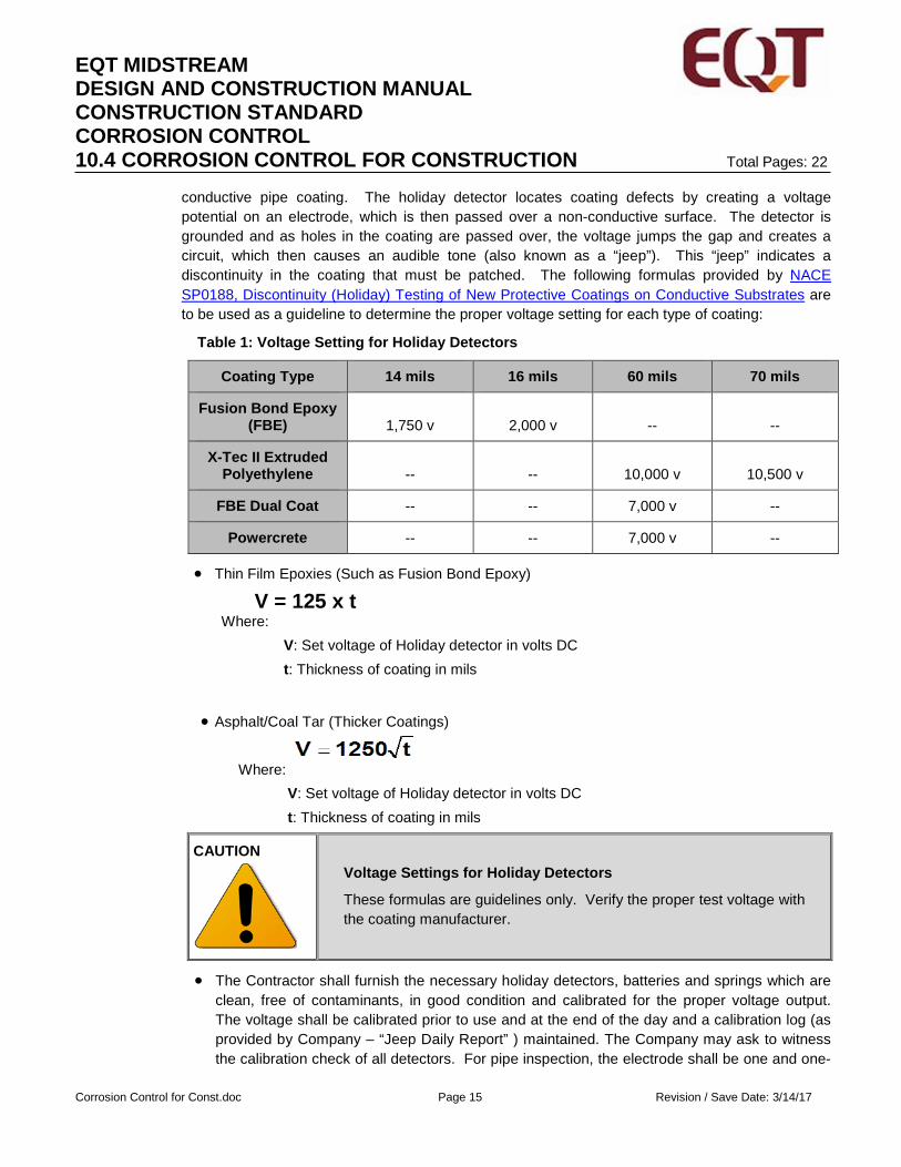
conductive pipe coating. The holiday detector locates coating defects by creating a voltage potential on an electrode, which is then passed over a non-conductive surface. The detector is grounded and as holes in the coating are passed over, the voltage jumps the gap and creates a circuit, which then causes an audible tone (also known as a “jeep”). This “jeep” indicates a discontinuity in the coating that must be patched. The following formulas provided by NACE SP0188, Discontinuity (Holiday) Testing of New Protective Coatings on Conductive Substrates are to be used as a guideline to determine the proper voltage setting for each type of coating:
Table 1: Voltage Setting for Holiday Detectors
Coating Type 14 mils 16 mils 60 mils 70 mils
Fusion Bond Epoxy (FBE) 1,750 v 2,000 v -- --
X-Tec II Extruded Polyethylene -- -- 10,000 v 10,500 v
FBE Dual Coat -- -- 7,000 v --
Powercrete -- -- 7,000 v --
• Thin Film Epoxies (Such as Fusion Bond Epoxy)
V = 125 x t Where:
V: Set voltage of Holiday detector in volts DC t: Thickness of coating in mils
• Asphalt/Coal Tar (Thicker Coatings) Where:
V: Set voltage of Holiday detector in volts DC t: Thickness of coating in mils
CAUTION
Voltage Settings for Holiday Detectors
These formulas are guidelines only. Verify the proper test voltage with the coating manufacturer.
• The Contractor shall furnish the necessary holiday detectors, batteries and springs which are clean, free of contaminants, in good condition and calibrated for the proper voltage output. The voltage shall be calibrated prior to use and at the end of the day and a calibration log (as provided by Company – “Jeep Daily Report” ) maintained. The Company may ask to witness the calibration check of all detectors. For pipe inspection, the electrode shall be one and one-

EQT MIDSTREAM DESIGN AND CONSTRUCTION MANUAL CONSTRUCTION STANDARD CORROSION CONTROL 10.4 CORROSION CONTROL FOR CONSTRUCTION Total Pages: 22
Corrosion Control for Const.doc Page 16 Revision / Save Date: 3/14/17
quarter (1.25) inches O.D. or one and one-half (1.5) inches O.D. rolling spring, composed of square stainless steel wire. The spring length shall not be less than ninety-five percent (95%) or more than one hundred percent (100%) of the pipe circumference.
• The contractor shall have a primary and backup holiday detector, and a crest voltmeter on the job site at all times.
• The coating shall be free of any excessive moisture, dirt, or electrically conductive material, which can cause current leakage or erroneous holiday indication. Drying and cleaning of the coated surface may be necessary. The speed of electrode travel shall be set as to ensure that all holidays are being detected. The Company shall test the holiday detector(s) used by the Contractor for the proper voltage setting. Adequate resistivity shall be considered and assured prior to using the earth surface as part of the circuit.
• For below grade pipeline appurtenances inspection, the electrode shall be a wet sponge detector supplied by the Contractor. Brush, squeegee or sponge type high-voltage holiday detector may be used when inspecting irregular shaped items (valves, fittings, etc.) coated with coal tar epoxy
• All coating defects found by visual or electronic inspection will be repaired by the Contractor, using approved material and methods, to the satisfaction of the Company.
• Long strings of pipeline that use the ground for the circuit will have total resistance evaluated by insuring the holiday detector is capable of finding a small defect. If concerns exist regarding the circuit, a small control defect will be installed in the coating at the end of the inspection run opposite of the ground to earth (where the circuit is the longest) to insure the methodology adequately detects the control defect
3 Cathodic Protection System Installation
Cathodic protection systems are installed to protect the exposed steel on coated pipe and protect bare pipe facilities from the corrosion process. The type of system selected is based on current requirements, surface area to be protected, environment in which the facility is installed, and the presence of potential interference current.
Cathodically protected systems need to be completely isolated from unprotected piping or facilities, unless specifically designed by a Corrosion Engineer to mitigate interference issues.
3.1 Galvanic Systems
Galvanic systems are typically used when there is a low current requirement (e.g. short pipelines, small diameter pipelines) or where commercial power is not available. Galvanic systems consist of sacrificial anodes (typically magnesium anodes) connected to the pipeline facility through a test station. The
CAUTION
One Call
It is required that all proper One Call procedures be followed before starting the installation of any cathodic protection systems.

EQT MIDSTREAM DESIGN AND CONSTRUCTION MANUAL CONSTRUCTION STANDARD CORROSION CONTROL 10.4 CORROSION CONTROL FOR CONSTRUCTION Total Pages: 22
Corrosion Control for Const.doc Page 17 Revision / Save Date: 3/14/17
installation of galvanic systems shall follow the drawings issued as part of the Project IFC drawing package. If issues or questions arise, contact a Corrosion Engineer before proceeding.
3.1.1 Galvanic System Installation
Galvanic system anode beds are depicted on the isometric drawings as T8 test stations. For installation information, see P-S-STANDARD-1204.
When installing galvanic systems:
• Remove the outer paper or plastic bag before burial of the anode.
• Do not carry the anode by the cable as it may become disconnected from the magnesium ingot.
• Do not remove the cloth sack that contains the gypsum backfill.
• Galvanic anodes must be installed in clean, rock-free backfill.
• Galvanic anodes should be installed two feet below the pipe. If this is not achievable, the top of the anode must be at least as deep as the bottom of the pipe.
3.2 Impressed Current Systems
Impressed current systems are typically used when the current requirements are higher (e.g. long pipelines, larger diameter pipelines, compressor stations, or areas of high interference currents). Impressed current systems use mixed metal oxides (MMO) anodes to protect a pipeline system. Rectifiers are used to produce a driving voltage used to increase the polarization of the facility being protected to in order to mitigate corrosion.
3.2.1 Impressed Current System Installation
• The installation of impressed current systems shall follow the drawings issued as part of the Project IFC drawing package. If issues or questions arise, contact a Corrosion Engineer before proceeding.
• The rectifiers, junction boxes (if required), and poles will be installed per drawings. The rectifier will be connected to the groundbed and pipe using #2 HMWPE cable. The cable from the positive side of the rectifier will have red insulation and attach to the anodes per the IFC drawings. The cable from the negative side of the rectifier will have black insulation and be connected to the pipe by exothermic welding per drawings and EQT Standards. The minimum depth of the cables is 24 inches. In cultivated fields, the minimum depth is 36 inches. Junction boxes will be wired as indicated on the IFC drawings.
• The 3-inch x 60 inch MMO anodes will be installed in the vertical or horizontal position per
CAUTION
Galvanic Anode System
DO NOT install galvanic (magnesium) anodes enclosed in a paper, plastic, or cloth bag, with coke breeze (carbon) backfill or connect them to the positive header cable (red cable) of a cathodic protection rectifier.

EQT MIDSTREAM DESIGN AND CONSTRUCTION MANUAL CONSTRUCTION STANDARD CORROSION CONTROL 10.4 CORROSION CONTROL FOR CONSTRUCTION Total Pages: 22
Corrosion Control for Const.doc Page 18 Revision / Save Date: 3/14/17
drawings in the Project IFC drawing package. If installed vertically, the anodes shall be installed in an individual borehole augured to the depth of at least 10 feet. The borehole should be 12 inches in diameter. The bottom of the borehole shall have 12 inches of coke breeze backfill poured into the hole. Install the anode in the borehole. Coke breeze shall be poured and tamped around the anode in the borehole. The anode is to be kept suspended and centralized during this operation. After settling, the coke breeze should be at least 12 inches above the anode. The anode boreholes shall be backfilled to the depth of the groundbed cable trench.
• If installed horizontally, a trench will be dug 7 feet long and at least 12 inches wide. Four hundred pounds of coke breeze will be installed in the bottom of the trench with the anodes placed on top and centered in the trench. An additional 400 pounds of coke breeze will be installed on top of the anodes. After the anodes have been installed, a #2 HMWPE cable with red insulation will be trenched between the groundbed test stations.
• All connections between anodes and header cable shall be made with the crimp and splice kit identified in the IFC drawings. Splices will remain exposed until the manufacturers required curing time has elapsed.
• When installing impressed current systems:
♦ Care must be taken not to damage the anodes or cables during the installation process. Any damage to the outer insulation of the cable will result in current discharge and failure of the cable.
♦ If a cable is hit or struck during construction, the Corrosion Operations or a Corrosion Engineer must be notified.
♦ It is critical that the proper type of anode is installed as identified in the Project IFC drawing package. Installation of any other type of anode will result in inadequate protection and significantly reduce groundbed life.
♦ If a cable crosses a road, a PVC conduit may be needed. Contact a Corrosion Engineer for further direction, should this occur.
♦ If during installation any unmarked cables are exposed, Corrosion Operations must be contacted.
CAUTION
Impressed Current System Anodes
DO NOT install galvanic (magnesium) anodes in an impressed current system. If the anode is enclosed in a paper, plastic, or cloth bag, it is not the proper anode to use for this type of system.
4 Test Station Installation
• Corrosion control test stations shall be of the upright design and installed by qualified persons. Wire and/or cable connections made to Company lines shall be made by qualified persons. Wire and/or cable connections made to Company lines using exothermic welds shall follow the Company's Safety Standards
EQT MIDSTREAM DESIGN AND CONSTRUCTION MANUAL CONSTRUCTION STANDARD CORROSION CONTROL 10.4 CORROSION CONTROL FOR CONSTRUCTION Total Pages: 22
Corrosion Control for Const.doc Page 19 Revision / Save Date: 3/14/17
for exothermic welding (MP102.01). Test stations that will include wire and/or cable connections to lines of foreign companies shall require such connections to be made by personnel of the foreign companies.
• Test station leads shall be attached to the pipe using a 15-gram exothermic weld charge. Installation of test stations shall be vertical and shall extend minimum of 2 - feet and maximum of 4 - feet above the finished grade of the right-of-way. The wire leading from the test station should be #8 AWG stranded wire with TW insulation or equivalent. On coated pipelines, the uninsulated portion of the test lead and the exothermic weld shall be coated with exothermic weld shall be coated with two-part epoxy, hot wax, or a Handicap device for cathodic protection All wires or cable connections must be tested to determine proper connections to the lines and all connections must be properly cleaned and coated. All bare wire exposed by insulation removal or damage must be coated.
• All wiring to test stations will conform to a color code in as shown in the drawings P-S-STANDARD-1204 “Cathodic Protection”. Red wires will always be used on the EQT pipeline and new protected pipeline sections. White wires will be used on foreign pipelines and bare pipeline sections or casing pipe. Black wires will always be used on anodes.
• All test wire or cable connections shall be made in a manner to avoid harmful stress concentration in the pipe at the point of connection. Minimum distance between exothermic welds shall be 6-inches. The exothermic welding process shall be used only on lines acceptable to the use of the process, and as related to existing lines, the process shall be applied only to non-deteriorated metal surfaces.
• Test stations should be installed at a minimum of every mile on a buried coated pipeline (Refer to standard drawing P-S-STANDARD-1204 “Cathodic Protection”). The actual placement of the test station should be in a somewhat protected area if possible and the exact placement is not critical. Fence lines, woodlands, and beside pipeline vent pipes are good locations for test stations.
• If test station installation involves galvanic anodes, the anodes must be connected to the pipe through the test station. Galvanic anodes are not to be connected directly to the pipe.
• At locations where the pipe is buried more than ten (10) feet deep, Company Design Engineering may elect to install a permanent reference cell buried at the depth of the pipeline. Horizontal directional drilled crossings often require these installations.
• Corrosion control test stations shall be installed at locations identified on the alignment sheets issued as part of the Project IFC drawing package. If any of the following are identified during construction, additional test stations should be added as follows:
♦ At foreign metallic line crossings (Type 4A or 4B or as dictated by the foreign company)
♦ At crossings of Company lines (Type 4A or 4B)
♦ At each side of waterways, certain roads and railroad crossings (Type 1, Type 2, or Type 2A)
5 Corrosion Surveys
Corrosion surveys will be conducted in accordance with the NACE Standards and Company Specifications listed in the Company Publications and Industry Standards section of this document. These surveys are conducted to prove the effectiveness of the cathodic protection systems and to check for coating anomalies. Corrosion surveys can be any combination of the following:
EQT MIDSTREAM DESIGN AND CONSTRUCTION MANUAL CONSTRUCTION STANDARD CORROSION CONTROL 10.4 CORROSION CONTROL FOR CONSTRUCTION Total Pages: 22
Corrosion Control for Const.doc Page 20 Revision / Save Date: 3/14/17
• Close Interval Potential Survey (CIPS),
• Alternating Current Voltage Gradient (ACVG) or
• Direct Current Voltage Gradient (DCVG).
These surveys will be conducted by qualified corrosion control consultants hired by EQT within the first year of operation. Results will be reviewed by a Corrosion Engineer or Designee. If remedial action is required, the Corrosion Engineer will coordinate with Construction and Corrosion Operations to determine necessary mitigation.
6 AC Mitigation Facilities Installation
Pipeline Construction near overhead high voltage electrical power lines requires that precautions be taken to minimize the potential electrical shock hazards. Design Standard 10.2 Pipeline Construction Specification covers the minimum precautions to be taken by the contractor while constructing in the vicinity of high voltage electrical power lines.
CAUTION
Construction in the Vicinity of High Voltage Electrical Power Lines
The potential hazard of electrical shock exists due to personnel coming into contact with pipe, equipment, or other metallic apparatuses during construction in the vicinity of high voltage electrical power lines.
In the event that the potential for AC interference is identified during the design phase of a pipeline project, a mitigation design will be completed and the Project Scope of Work will detail the responsibility for construction and material acquisition. The AC mitigation system design will be detailed in drawings included in the Project IFC drawing package. The drawings will include installation details regarding zinc ribbon locations, depth and clearance from the pipeline of the zinc ribbon, zinc ribbon splicing details, zinc ribbon connection to cable details, Solid-State Decoupler (SSD) installation, and cable connection to the pipeline via exothermic welding.
An electrical inspector with experience in AC mitigation is required during these installations.
The AC mitigation system will consist of all or some of these facilities:
6.1 Zinc Ribbon
Zinc ribbon is buried between the pipeline and the electrical power lines. The zinc ribbon acts as an electrical shield during power line fault events and ground for induced AC to reduce it to a negligible level. The zinc ribbon will be connected to the pipeline at certain intervals through SSDs.
6.2 Solid-State Decoupler
The SSD functions as a DC isolation device and AC coupling device. The SSD is used to isolate the cathodic protection system for the pipeline from the zinc ribbon being used as an AC ground thus preserving the cathodic protection levels along the pipeline. An SSD is connected between the zinc ribbon and the pipeline via cables. The SSD is mounted in an SSD Pedestal.
6.3 Gradient Control Mats
Gradient control mats are used to reduce the potential difference between the surface of the ground and pipeline. Gradient control mats are used around above ground appurtenances such as test stations,
EQT MIDSTREAM DESIGN AND CONSTRUCTION MANUAL CONSTRUCTION STANDARD CORROSION CONTROL 10.4 CORROSION CONTROL FOR CONSTRUCTION Total Pages: 22
Corrosion Control for Const.doc Page 21 Revision / Save Date: 3/14/17
buried valve extensions, blowoffs, etc. The mats are typically constructed with zinc ribbon or concrete reinforcing wire and connected to the pipeline through an SSD.
EQT MIDSTREAM DESIGN AND CONSTRUCTION MANUAL CONSTRUCTION STANDARD CORROSION CONTROL 10.4 CORROSION CONTROL FOR CONSTRUCTION Total Pages: 22
Corrosion Control for Const.doc Page 22 Revision / Save Date: 3/14/17
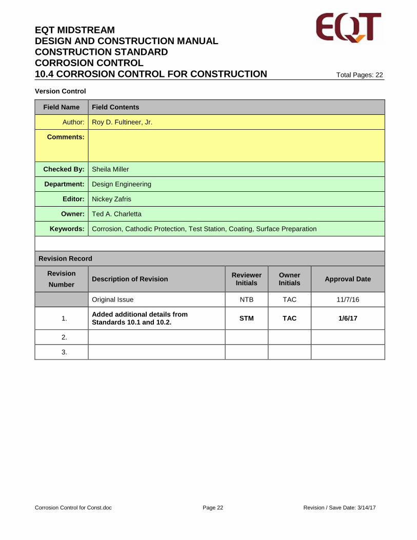
Version Control
Field Name Field Contents
Author: Roy D. Fultineer, Jr.
Comments:
Checked By: Sheila Miller
Department: Design Engineering
Editor: Nickey Zafris
Owner: Ted A. Charletta
Keywords: Corrosion, Cathodic Protection, Test Station, Coating, Surface Preparation
Revision Record
Revision Number
Description of Revision Reviewer Initials
Owner Initials Approval Date
Original Issue NTB TAC 11/7/16
1. Added additional details from Standards 10.1 and 10.2. STM TAC 1/6/17
2.
3.